WO2011030670A1 - 車両用モータ駆動装置および自動車 - Google Patents
車両用モータ駆動装置および自動車 Download PDFInfo
- Publication number
- WO2011030670A1 WO2011030670A1 PCT/JP2010/064442 JP2010064442W WO2011030670A1 WO 2011030670 A1 WO2011030670 A1 WO 2011030670A1 JP 2010064442 W JP2010064442 W JP 2010064442W WO 2011030670 A1 WO2011030670 A1 WO 2011030670A1
- Authority
- WO
- WIPO (PCT)
- Prior art keywords
- shift
- gear
- drive device
- motor drive
- way roller
- Prior art date
Links
Images


Classifications
-
- B—PERFORMING OPERATIONS; TRANSPORTING
- B60—VEHICLES IN GENERAL
- B60K—ARRANGEMENT OR MOUNTING OF PROPULSION UNITS OR OF TRANSMISSIONS IN VEHICLES; ARRANGEMENT OR MOUNTING OF PLURAL DIVERSE PRIME-MOVERS IN VEHICLES; AUXILIARY DRIVES FOR VEHICLES; INSTRUMENTATION OR DASHBOARDS FOR VEHICLES; ARRANGEMENTS IN CONNECTION WITH COOLING, AIR INTAKE, GAS EXHAUST OR FUEL SUPPLY OF PROPULSION UNITS IN VEHICLES
- B60K6/00—Arrangement or mounting of plural diverse prime-movers for mutual or common propulsion, e.g. hybrid propulsion systems comprising electric motors and internal combustion engines ; Control systems therefor, i.e. systems controlling two or more prime movers, or controlling one of these prime movers and any of the transmission, drive or drive units Informative references: mechanical gearings with secondary electric drive F16H3/72; arrangements for handling mechanical energy structurally associated with the dynamo-electric machine H02K7/00; machines comprising structurally interrelated motor and generator parts H02K51/00; dynamo-electric machines not otherwise provided for in H02K see H02K99/00
- B60K6/20—Arrangement or mounting of plural diverse prime-movers for mutual or common propulsion, e.g. hybrid propulsion systems comprising electric motors and internal combustion engines ; Control systems therefor, i.e. systems controlling two or more prime movers, or controlling one of these prime movers and any of the transmission, drive or drive units Informative references: mechanical gearings with secondary electric drive F16H3/72; arrangements for handling mechanical energy structurally associated with the dynamo-electric machine H02K7/00; machines comprising structurally interrelated motor and generator parts H02K51/00; dynamo-electric machines not otherwise provided for in H02K see H02K99/00 the prime-movers consisting of electric motors and internal combustion engines, e.g. HEVs
- B60K6/50—Architecture of the driveline characterised by arrangement or kind of transmission units
- B60K6/52—Driving a plurality of drive axles, e.g. four-wheel drive
-
- B—PERFORMING OPERATIONS; TRANSPORTING
- B60—VEHICLES IN GENERAL
- B60K—ARRANGEMENT OR MOUNTING OF PROPULSION UNITS OR OF TRANSMISSIONS IN VEHICLES; ARRANGEMENT OR MOUNTING OF PLURAL DIVERSE PRIME-MOVERS IN VEHICLES; AUXILIARY DRIVES FOR VEHICLES; INSTRUMENTATION OR DASHBOARDS FOR VEHICLES; ARRANGEMENTS IN CONNECTION WITH COOLING, AIR INTAKE, GAS EXHAUST OR FUEL SUPPLY OF PROPULSION UNITS IN VEHICLES
- B60K17/00—Arrangement or mounting of transmissions in vehicles
- B60K17/34—Arrangement or mounting of transmissions in vehicles for driving both front and rear wheels, e.g. four wheel drive vehicles
- B60K17/356—Arrangement or mounting of transmissions in vehicles for driving both front and rear wheels, e.g. four wheel drive vehicles having fluid or electric motor, for driving one or more wheels
-
- B—PERFORMING OPERATIONS; TRANSPORTING
- B60—VEHICLES IN GENERAL
- B60K—ARRANGEMENT OR MOUNTING OF PROPULSION UNITS OR OF TRANSMISSIONS IN VEHICLES; ARRANGEMENT OR MOUNTING OF PLURAL DIVERSE PRIME-MOVERS IN VEHICLES; AUXILIARY DRIVES FOR VEHICLES; INSTRUMENTATION OR DASHBOARDS FOR VEHICLES; ARRANGEMENTS IN CONNECTION WITH COOLING, AIR INTAKE, GAS EXHAUST OR FUEL SUPPLY OF PROPULSION UNITS IN VEHICLES
- B60K6/00—Arrangement or mounting of plural diverse prime-movers for mutual or common propulsion, e.g. hybrid propulsion systems comprising electric motors and internal combustion engines ; Control systems therefor, i.e. systems controlling two or more prime movers, or controlling one of these prime movers and any of the transmission, drive or drive units Informative references: mechanical gearings with secondary electric drive F16H3/72; arrangements for handling mechanical energy structurally associated with the dynamo-electric machine H02K7/00; machines comprising structurally interrelated motor and generator parts H02K51/00; dynamo-electric machines not otherwise provided for in H02K see H02K99/00
- B60K6/20—Arrangement or mounting of plural diverse prime-movers for mutual or common propulsion, e.g. hybrid propulsion systems comprising electric motors and internal combustion engines ; Control systems therefor, i.e. systems controlling two or more prime movers, or controlling one of these prime movers and any of the transmission, drive or drive units Informative references: mechanical gearings with secondary electric drive F16H3/72; arrangements for handling mechanical energy structurally associated with the dynamo-electric machine H02K7/00; machines comprising structurally interrelated motor and generator parts H02K51/00; dynamo-electric machines not otherwise provided for in H02K see H02K99/00 the prime-movers consisting of electric motors and internal combustion engines, e.g. HEVs
- B60K6/22—Arrangement or mounting of plural diverse prime-movers for mutual or common propulsion, e.g. hybrid propulsion systems comprising electric motors and internal combustion engines ; Control systems therefor, i.e. systems controlling two or more prime movers, or controlling one of these prime movers and any of the transmission, drive or drive units Informative references: mechanical gearings with secondary electric drive F16H3/72; arrangements for handling mechanical energy structurally associated with the dynamo-electric machine H02K7/00; machines comprising structurally interrelated motor and generator parts H02K51/00; dynamo-electric machines not otherwise provided for in H02K see H02K99/00 the prime-movers consisting of electric motors and internal combustion engines, e.g. HEVs characterised by apparatus, components or means specially adapted for HEVs
- B60K6/38—Arrangement or mounting of plural diverse prime-movers for mutual or common propulsion, e.g. hybrid propulsion systems comprising electric motors and internal combustion engines ; Control systems therefor, i.e. systems controlling two or more prime movers, or controlling one of these prime movers and any of the transmission, drive or drive units Informative references: mechanical gearings with secondary electric drive F16H3/72; arrangements for handling mechanical energy structurally associated with the dynamo-electric machine H02K7/00; machines comprising structurally interrelated motor and generator parts H02K51/00; dynamo-electric machines not otherwise provided for in H02K see H02K99/00 the prime-movers consisting of electric motors and internal combustion engines, e.g. HEVs characterised by apparatus, components or means specially adapted for HEVs characterised by the driveline clutches
- B60K6/383—One-way clutches or freewheel devices
-
- B—PERFORMING OPERATIONS; TRANSPORTING
- B60—VEHICLES IN GENERAL
- B60K—ARRANGEMENT OR MOUNTING OF PROPULSION UNITS OR OF TRANSMISSIONS IN VEHICLES; ARRANGEMENT OR MOUNTING OF PLURAL DIVERSE PRIME-MOVERS IN VEHICLES; AUXILIARY DRIVES FOR VEHICLES; INSTRUMENTATION OR DASHBOARDS FOR VEHICLES; ARRANGEMENTS IN CONNECTION WITH COOLING, AIR INTAKE, GAS EXHAUST OR FUEL SUPPLY OF PROPULSION UNITS IN VEHICLES
- B60K6/00—Arrangement or mounting of plural diverse prime-movers for mutual or common propulsion, e.g. hybrid propulsion systems comprising electric motors and internal combustion engines ; Control systems therefor, i.e. systems controlling two or more prime movers, or controlling one of these prime movers and any of the transmission, drive or drive units Informative references: mechanical gearings with secondary electric drive F16H3/72; arrangements for handling mechanical energy structurally associated with the dynamo-electric machine H02K7/00; machines comprising structurally interrelated motor and generator parts H02K51/00; dynamo-electric machines not otherwise provided for in H02K see H02K99/00
- B60K6/20—Arrangement or mounting of plural diverse prime-movers for mutual or common propulsion, e.g. hybrid propulsion systems comprising electric motors and internal combustion engines ; Control systems therefor, i.e. systems controlling two or more prime movers, or controlling one of these prime movers and any of the transmission, drive or drive units Informative references: mechanical gearings with secondary electric drive F16H3/72; arrangements for handling mechanical energy structurally associated with the dynamo-electric machine H02K7/00; machines comprising structurally interrelated motor and generator parts H02K51/00; dynamo-electric machines not otherwise provided for in H02K see H02K99/00 the prime-movers consisting of electric motors and internal combustion engines, e.g. HEVs
- B60K6/50—Architecture of the driveline characterised by arrangement or kind of transmission units
- B60K6/54—Transmission for changing ratio
- B60K6/547—Transmission for changing ratio the transmission being a stepped gearing
-
- B—PERFORMING OPERATIONS; TRANSPORTING
- B60—VEHICLES IN GENERAL
- B60L—PROPULSION OF ELECTRICALLY-PROPELLED VEHICLES; SUPPLYING ELECTRIC POWER FOR AUXILIARY EQUIPMENT OF ELECTRICALLY-PROPELLED VEHICLES; ELECTRODYNAMIC BRAKE SYSTEMS FOR VEHICLES IN GENERAL; MAGNETIC SUSPENSION OR LEVITATION FOR VEHICLES; MONITORING OPERATING VARIABLES OF ELECTRICALLY-PROPELLED VEHICLES; ELECTRIC SAFETY DEVICES FOR ELECTRICALLY-PROPELLED VEHICLES
- B60L15/00—Methods, circuits, or devices for controlling the traction-motor speed of electrically-propelled vehicles
- B60L15/20—Methods, circuits, or devices for controlling the traction-motor speed of electrically-propelled vehicles for control of the vehicle or its driving motor to achieve a desired performance, e.g. speed, torque, programmed variation of speed
-
- B—PERFORMING OPERATIONS; TRANSPORTING
- B60—VEHICLES IN GENERAL
- B60L—PROPULSION OF ELECTRICALLY-PROPELLED VEHICLES; SUPPLYING ELECTRIC POWER FOR AUXILIARY EQUIPMENT OF ELECTRICALLY-PROPELLED VEHICLES; ELECTRODYNAMIC BRAKE SYSTEMS FOR VEHICLES IN GENERAL; MAGNETIC SUSPENSION OR LEVITATION FOR VEHICLES; MONITORING OPERATING VARIABLES OF ELECTRICALLY-PROPELLED VEHICLES; ELECTRIC SAFETY DEVICES FOR ELECTRICALLY-PROPELLED VEHICLES
- B60L50/00—Electric propulsion with power supplied within the vehicle
- B60L50/10—Electric propulsion with power supplied within the vehicle using propulsion power supplied by engine-driven generators, e.g. generators driven by combustion engines
- B60L50/16—Electric propulsion with power supplied within the vehicle using propulsion power supplied by engine-driven generators, e.g. generators driven by combustion engines with provision for separate direct mechanical propulsion
-
- B—PERFORMING OPERATIONS; TRANSPORTING
- B60—VEHICLES IN GENERAL
- B60L—PROPULSION OF ELECTRICALLY-PROPELLED VEHICLES; SUPPLYING ELECTRIC POWER FOR AUXILIARY EQUIPMENT OF ELECTRICALLY-PROPELLED VEHICLES; ELECTRODYNAMIC BRAKE SYSTEMS FOR VEHICLES IN GENERAL; MAGNETIC SUSPENSION OR LEVITATION FOR VEHICLES; MONITORING OPERATING VARIABLES OF ELECTRICALLY-PROPELLED VEHICLES; ELECTRIC SAFETY DEVICES FOR ELECTRICALLY-PROPELLED VEHICLES
- B60L50/00—Electric propulsion with power supplied within the vehicle
- B60L50/50—Electric propulsion with power supplied within the vehicle using propulsion power supplied by batteries or fuel cells
- B60L50/60—Electric propulsion with power supplied within the vehicle using propulsion power supplied by batteries or fuel cells using power supplied by batteries
- B60L50/61—Electric propulsion with power supplied within the vehicle using propulsion power supplied by batteries or fuel cells using power supplied by batteries by batteries charged by engine-driven generators, e.g. series hybrid electric vehicles
-
- F—MECHANICAL ENGINEERING; LIGHTING; HEATING; WEAPONS; BLASTING
- F16—ENGINEERING ELEMENTS AND UNITS; GENERAL MEASURES FOR PRODUCING AND MAINTAINING EFFECTIVE FUNCTIONING OF MACHINES OR INSTALLATIONS; THERMAL INSULATION IN GENERAL
- F16D—COUPLINGS FOR TRANSMITTING ROTATION; CLUTCHES; BRAKES
- F16D41/00—Freewheels or freewheel clutches
- F16D41/06—Freewheels or freewheel clutches with intermediate wedging coupling members between an inner and an outer surface
- F16D41/08—Freewheels or freewheel clutches with intermediate wedging coupling members between an inner and an outer surface with provision for altering the freewheeling action
- F16D41/086—Freewheels or freewheel clutches with intermediate wedging coupling members between an inner and an outer surface with provision for altering the freewheeling action the intermediate members being of circular cross-section and wedging by rolling
- F16D41/088—Freewheels or freewheel clutches with intermediate wedging coupling members between an inner and an outer surface with provision for altering the freewheeling action the intermediate members being of circular cross-section and wedging by rolling the intermediate members being of only one size and wedging by a movement not having an axial component, between inner and outer races, one of which is cylindrical
-
- F—MECHANICAL ENGINEERING; LIGHTING; HEATING; WEAPONS; BLASTING
- F16—ENGINEERING ELEMENTS AND UNITS; GENERAL MEASURES FOR PRODUCING AND MAINTAINING EFFECTIVE FUNCTIONING OF MACHINES OR INSTALLATIONS; THERMAL INSULATION IN GENERAL
- F16H—GEARING
- F16H3/00—Toothed gearings for conveying rotary motion with variable gear ratio or for reversing rotary motion
- F16H3/02—Toothed gearings for conveying rotary motion with variable gear ratio or for reversing rotary motion without gears having orbital motion
- F16H3/08—Toothed gearings for conveying rotary motion with variable gear ratio or for reversing rotary motion without gears having orbital motion exclusively or essentially with continuously meshing gears, that can be disengaged from their shafts
- F16H3/10—Toothed gearings for conveying rotary motion with variable gear ratio or for reversing rotary motion without gears having orbital motion exclusively or essentially with continuously meshing gears, that can be disengaged from their shafts with one or more one-way clutches as an essential feature
-
- F—MECHANICAL ENGINEERING; LIGHTING; HEATING; WEAPONS; BLASTING
- F16—ENGINEERING ELEMENTS AND UNITS; GENERAL MEASURES FOR PRODUCING AND MAINTAINING EFFECTIVE FUNCTIONING OF MACHINES OR INSTALLATIONS; THERMAL INSULATION IN GENERAL
- F16H—GEARING
- F16H63/00—Control outputs from the control unit to change-speed- or reversing-gearings for conveying rotary motion or to other devices than the final output mechanism
- F16H63/02—Final output mechanisms therefor; Actuating means for the final output mechanisms
- F16H63/30—Constructional features of the final output mechanisms
-
- B—PERFORMING OPERATIONS; TRANSPORTING
- B60—VEHICLES IN GENERAL
- B60K—ARRANGEMENT OR MOUNTING OF PROPULSION UNITS OR OF TRANSMISSIONS IN VEHICLES; ARRANGEMENT OR MOUNTING OF PLURAL DIVERSE PRIME-MOVERS IN VEHICLES; AUXILIARY DRIVES FOR VEHICLES; INSTRUMENTATION OR DASHBOARDS FOR VEHICLES; ARRANGEMENTS IN CONNECTION WITH COOLING, AIR INTAKE, GAS EXHAUST OR FUEL SUPPLY OF PROPULSION UNITS IN VEHICLES
- B60K1/00—Arrangement or mounting of electrical propulsion units
-
- B—PERFORMING OPERATIONS; TRANSPORTING
- B60—VEHICLES IN GENERAL
- B60K—ARRANGEMENT OR MOUNTING OF PROPULSION UNITS OR OF TRANSMISSIONS IN VEHICLES; ARRANGEMENT OR MOUNTING OF PLURAL DIVERSE PRIME-MOVERS IN VEHICLES; AUXILIARY DRIVES FOR VEHICLES; INSTRUMENTATION OR DASHBOARDS FOR VEHICLES; ARRANGEMENTS IN CONNECTION WITH COOLING, AIR INTAKE, GAS EXHAUST OR FUEL SUPPLY OF PROPULSION UNITS IN VEHICLES
- B60K17/00—Arrangement or mounting of transmissions in vehicles
- B60K17/04—Arrangement or mounting of transmissions in vehicles characterised by arrangement, location, or kind of gearing
- B60K17/16—Arrangement or mounting of transmissions in vehicles characterised by arrangement, location, or kind of gearing of differential gearing
- B60K17/165—Arrangement or mounting of transmissions in vehicles characterised by arrangement, location, or kind of gearing of differential gearing provided between independent half axles
-
- B—PERFORMING OPERATIONS; TRANSPORTING
- B60—VEHICLES IN GENERAL
- B60K—ARRANGEMENT OR MOUNTING OF PROPULSION UNITS OR OF TRANSMISSIONS IN VEHICLES; ARRANGEMENT OR MOUNTING OF PLURAL DIVERSE PRIME-MOVERS IN VEHICLES; AUXILIARY DRIVES FOR VEHICLES; INSTRUMENTATION OR DASHBOARDS FOR VEHICLES; ARRANGEMENTS IN CONNECTION WITH COOLING, AIR INTAKE, GAS EXHAUST OR FUEL SUPPLY OF PROPULSION UNITS IN VEHICLES
- B60K1/00—Arrangement or mounting of electrical propulsion units
- B60K2001/001—Arrangement or mounting of electrical propulsion units one motor mounted on a propulsion axle for rotating right and left wheels of this axle
-
- B—PERFORMING OPERATIONS; TRANSPORTING
- B60—VEHICLES IN GENERAL
- B60L—PROPULSION OF ELECTRICALLY-PROPELLED VEHICLES; SUPPLYING ELECTRIC POWER FOR AUXILIARY EQUIPMENT OF ELECTRICALLY-PROPELLED VEHICLES; ELECTRODYNAMIC BRAKE SYSTEMS FOR VEHICLES IN GENERAL; MAGNETIC SUSPENSION OR LEVITATION FOR VEHICLES; MONITORING OPERATING VARIABLES OF ELECTRICALLY-PROPELLED VEHICLES; ELECTRIC SAFETY DEVICES FOR ELECTRICALLY-PROPELLED VEHICLES
- B60L2220/00—Electrical machine types; Structures or applications thereof
- B60L2220/10—Electrical machine types
- B60L2220/14—Synchronous machines
-
- B—PERFORMING OPERATIONS; TRANSPORTING
- B60—VEHICLES IN GENERAL
- B60L—PROPULSION OF ELECTRICALLY-PROPELLED VEHICLES; SUPPLYING ELECTRIC POWER FOR AUXILIARY EQUIPMENT OF ELECTRICALLY-PROPELLED VEHICLES; ELECTRODYNAMIC BRAKE SYSTEMS FOR VEHICLES IN GENERAL; MAGNETIC SUSPENSION OR LEVITATION FOR VEHICLES; MONITORING OPERATING VARIABLES OF ELECTRICALLY-PROPELLED VEHICLES; ELECTRIC SAFETY DEVICES FOR ELECTRICALLY-PROPELLED VEHICLES
- B60L2240/00—Control parameters of input or output; Target parameters
- B60L2240/40—Drive Train control parameters
- B60L2240/42—Drive Train control parameters related to electric machines
- B60L2240/421—Speed
-
- B—PERFORMING OPERATIONS; TRANSPORTING
- B60—VEHICLES IN GENERAL
- B60L—PROPULSION OF ELECTRICALLY-PROPELLED VEHICLES; SUPPLYING ELECTRIC POWER FOR AUXILIARY EQUIPMENT OF ELECTRICALLY-PROPELLED VEHICLES; ELECTRODYNAMIC BRAKE SYSTEMS FOR VEHICLES IN GENERAL; MAGNETIC SUSPENSION OR LEVITATION FOR VEHICLES; MONITORING OPERATING VARIABLES OF ELECTRICALLY-PROPELLED VEHICLES; ELECTRIC SAFETY DEVICES FOR ELECTRICALLY-PROPELLED VEHICLES
- B60L2240/00—Control parameters of input or output; Target parameters
- B60L2240/40—Drive Train control parameters
- B60L2240/42—Drive Train control parameters related to electric machines
- B60L2240/423—Torque
-
- B—PERFORMING OPERATIONS; TRANSPORTING
- B60—VEHICLES IN GENERAL
- B60L—PROPULSION OF ELECTRICALLY-PROPELLED VEHICLES; SUPPLYING ELECTRIC POWER FOR AUXILIARY EQUIPMENT OF ELECTRICALLY-PROPELLED VEHICLES; ELECTRODYNAMIC BRAKE SYSTEMS FOR VEHICLES IN GENERAL; MAGNETIC SUSPENSION OR LEVITATION FOR VEHICLES; MONITORING OPERATING VARIABLES OF ELECTRICALLY-PROPELLED VEHICLES; ELECTRIC SAFETY DEVICES FOR ELECTRICALLY-PROPELLED VEHICLES
- B60L2260/00—Operating Modes
- B60L2260/20—Drive modes; Transition between modes
- B60L2260/28—Four wheel or all wheel drive
-
- F—MECHANICAL ENGINEERING; LIGHTING; HEATING; WEAPONS; BLASTING
- F16—ENGINEERING ELEMENTS AND UNITS; GENERAL MEASURES FOR PRODUCING AND MAINTAINING EFFECTIVE FUNCTIONING OF MACHINES OR INSTALLATIONS; THERMAL INSULATION IN GENERAL
- F16D—COUPLINGS FOR TRANSMITTING ROTATION; CLUTCHES; BRAKES
- F16D2500/00—External control of clutches by electric or electronic means
- F16D2500/10—System to be controlled
- F16D2500/104—Clutch
- F16D2500/10443—Clutch type
- F16D2500/10493—One way clutch
-
- F—MECHANICAL ENGINEERING; LIGHTING; HEATING; WEAPONS; BLASTING
- F16—ENGINEERING ELEMENTS AND UNITS; GENERAL MEASURES FOR PRODUCING AND MAINTAINING EFFECTIVE FUNCTIONING OF MACHINES OR INSTALLATIONS; THERMAL INSULATION IN GENERAL
- F16H—GEARING
- F16H63/00—Control outputs from the control unit to change-speed- or reversing-gearings for conveying rotary motion or to other devices than the final output mechanism
- F16H63/02—Final output mechanisms therefor; Actuating means for the final output mechanisms
- F16H63/30—Constructional features of the final output mechanisms
- F16H2063/3093—Final output elements, i.e. the final elements to establish gear ratio, e.g. dog clutches or other means establishing coupling to shaft
-
- F—MECHANICAL ENGINEERING; LIGHTING; HEATING; WEAPONS; BLASTING
- F16—ENGINEERING ELEMENTS AND UNITS; GENERAL MEASURES FOR PRODUCING AND MAINTAINING EFFECTIVE FUNCTIONING OF MACHINES OR INSTALLATIONS; THERMAL INSULATION IN GENERAL
- F16H—GEARING
- F16H2200/00—Transmissions for multiple ratios
- F16H2200/0021—Transmissions for multiple ratios specially adapted for electric vehicles
-
- F—MECHANICAL ENGINEERING; LIGHTING; HEATING; WEAPONS; BLASTING
- F16—ENGINEERING ELEMENTS AND UNITS; GENERAL MEASURES FOR PRODUCING AND MAINTAINING EFFECTIVE FUNCTIONING OF MACHINES OR INSTALLATIONS; THERMAL INSULATION IN GENERAL
- F16H—GEARING
- F16H2200/00—Transmissions for multiple ratios
- F16H2200/003—Transmissions for multiple ratios characterised by the number of forward speeds
- F16H2200/0034—Transmissions for multiple ratios characterised by the number of forward speeds the gear ratios comprising two forward speeds
-
- F—MECHANICAL ENGINEERING; LIGHTING; HEATING; WEAPONS; BLASTING
- F16—ENGINEERING ELEMENTS AND UNITS; GENERAL MEASURES FOR PRODUCING AND MAINTAINING EFFECTIVE FUNCTIONING OF MACHINES OR INSTALLATIONS; THERMAL INSULATION IN GENERAL
- F16H—GEARING
- F16H48/00—Differential gearings
- F16H48/06—Differential gearings with gears having orbital motion
- F16H48/08—Differential gearings with gears having orbital motion comprising bevel gears
-
- Y—GENERAL TAGGING OF NEW TECHNOLOGICAL DEVELOPMENTS; GENERAL TAGGING OF CROSS-SECTIONAL TECHNOLOGIES SPANNING OVER SEVERAL SECTIONS OF THE IPC; TECHNICAL SUBJECTS COVERED BY FORMER USPC CROSS-REFERENCE ART COLLECTIONS [XRACs] AND DIGESTS
- Y02—TECHNOLOGIES OR APPLICATIONS FOR MITIGATION OR ADAPTATION AGAINST CLIMATE CHANGE
- Y02T—CLIMATE CHANGE MITIGATION TECHNOLOGIES RELATED TO TRANSPORTATION
- Y02T10/00—Road transport of goods or passengers
- Y02T10/60—Other road transportation technologies with climate change mitigation effect
- Y02T10/62—Hybrid vehicles
-
- Y—GENERAL TAGGING OF NEW TECHNOLOGICAL DEVELOPMENTS; GENERAL TAGGING OF CROSS-SECTIONAL TECHNOLOGIES SPANNING OVER SEVERAL SECTIONS OF THE IPC; TECHNICAL SUBJECTS COVERED BY FORMER USPC CROSS-REFERENCE ART COLLECTIONS [XRACs] AND DIGESTS
- Y02—TECHNOLOGIES OR APPLICATIONS FOR MITIGATION OR ADAPTATION AGAINST CLIMATE CHANGE
- Y02T—CLIMATE CHANGE MITIGATION TECHNOLOGIES RELATED TO TRANSPORTATION
- Y02T10/00—Road transport of goods or passengers
- Y02T10/60—Other road transportation technologies with climate change mitigation effect
- Y02T10/70—Energy storage systems for electromobility, e.g. batteries
-
- Y—GENERAL TAGGING OF NEW TECHNOLOGICAL DEVELOPMENTS; GENERAL TAGGING OF CROSS-SECTIONAL TECHNOLOGIES SPANNING OVER SEVERAL SECTIONS OF THE IPC; TECHNICAL SUBJECTS COVERED BY FORMER USPC CROSS-REFERENCE ART COLLECTIONS [XRACs] AND DIGESTS
- Y02—TECHNOLOGIES OR APPLICATIONS FOR MITIGATION OR ADAPTATION AGAINST CLIMATE CHANGE
- Y02T—CLIMATE CHANGE MITIGATION TECHNOLOGIES RELATED TO TRANSPORTATION
- Y02T10/00—Road transport of goods or passengers
- Y02T10/60—Other road transportation technologies with climate change mitigation effect
- Y02T10/72—Electric energy management in electromobility
Definitions
- the present invention relates to a vehicle motor drive device that includes an electric motor as a drive source, decelerates the output of the electric motor, and transmits the output to wheels, and an automobile equipped with the motor drive device.
- Patent Documents 1 and 2 are known as vehicle motor drive devices used in drive devices for electric vehicles and hybrid vehicles.
- the rotation of the motor is input to a transmission composed of a belt type continuously variable transmission (CVT) or a planetary gear type transmission to change the speed.
- the rotation output from the machine is input to the differential gear to rotate the left and right auxiliary drive wheels (rear wheels).
- the rotation output from the motor is input to the transmission of the planetary gear type transmission for shifting, and the rotation output from the transmission is transmitted to the differential gear.
- the left and right auxiliary drive wheels (rear wheels) are rotated.
- the transmission can be switched to a Lo gear state, a Hi gear state, and a neutral state by sliding a key provided on the transmission. Therefore, by switching to the neutral state, it is possible to prevent the transmission and the motor from rotating from the auxiliary drive wheel, but the key is slid to connect the ring gear of the planetary gear mechanism and the casing, Alternatively, the two parts cannot be coupled unless the two members that rotate relative to each other are synchronized and the difference in relative rotational speed is reduced when switching the gear shift that couples the ring gear and the sun gear. For this reason, the time required for synchronization is long, and during that time, the vehicle is in an idling state, which reduces drivability and merchantability.
- An object of the present invention is to provide a vehicle motor drive device, an electric vehicle, and a hybrid vehicle that can be prevented from being rotated from the wheel side and that can perform speed change switching quickly. It is.
- a plurality of gear trains having different gear ratios are provided between the electric motor and the parallel shaft, and the torque transmission path of the gear train is switched.
- a continuously meshing transmission that shifts the rotation output from the electric motor to a plurality of stages, a differential gear that distributes the power output from the transmission to the left and right wheels, and the roller and the roller are held.
- Two-way roller clutches having the same number of gear trains that are engaged and released by rotation control of the cage and that engage and release the gears for each gear stage with respect to the parallel shaft.
- a shift switching actuator that controls the rotation of the cage of the 2-way roller clutch and switches the torque transmission path by engaging and releasing the 2-way roller clutch. Than is adopted the configuration.
- the parallel shaft and the gear are brought into an engaged state by engaging one of the two-way roller clutches incorporated in the gear train of each shift stage by the operation of the shift switching actuator.
- the rotation of the electric motor is changed by the engaged gear train and transmitted to the differential gear, and the left and right wheels rotate.
- the electric vehicle according to the present invention employs a configuration in which at least one of the pair of left and right front wheels provided at the front portion of the vehicle and the pair of left and right rear wheels provided at the rear portion is driven by the motor driving device. .
- one of the pair of left and right front wheels provided at the front portion of the vehicle and the pair of left and right rear wheels provided at the rear portion is driven by the engine, and the other is driven by the motor drive device described above.
- the driving structure was adopted.
- the transmission and the motor are rotated from the wheel side driven by the motor by setting the two-way roller clutch in the released state when the vehicle is driven by the engine. Can be prevented and energy loss can be suppressed.
- a two-way roller clutch As a two-way roller clutch, it has an inner ring that is incorporated between a parallel shaft and a gear and is prevented from rotating around the parallel shaft.
- a cylindrical surface is formed on one of the outer periphery of the inner ring and the inner periphery of the gear, and the other
- a cam surface is formed between the cylindrical surface and the cylindrical surface to form a narrow wedge space at both ends in the circumferential direction.
- a roller is assembled between the cam surface and the cylindrical surface, and the roller is held by a cage assembled between the gear and the inner ring.
- a switch spring for elastically holding the cage in a neutral position where the roller is disengaged from the cylindrical surface and the cam surface between the member on the side where the cam surface is formed and the cage.
- a friction plate that is prevented from rotating by a cage and is movable toward one side of the member on which the cylindrical surface is formed, and the friction plate is formed with a cylindrical surface
- An elastic member that urges toward a disengagement position that is separated from the member, and is slidably supported by the parallel shaft and moved toward the member on which the cylindrical surface is formed, and friction is caused on one side surface of the member.
- a control ring that presses the plate, a sleeve that is rotatably supported on the outer periphery of the control ring, and a shift mechanism that shifts the sleeve toward the member having the cylindrical surface can be employed.
- an electronic control device for controlling the operation of the shift switch actuator and the electric motor.
- the shift control command is received as the electronic control device
- the two-way roller clutch of the current shift stage is provided.
- the gear change actuator is operated so that the friction plate is separated from the member on which the cylindrical surface is formed. At this time, has the friction plate separated from the member on which the cylindrical surface of the two-way roller clutch of the current gear stage is formed? After determining whether or not the friction plate has separated, control is performed to change the motor torque of the electric motor to a magnitude that allows the two-way roller clutch of the current gear to be disengaged.
- a shift mechanism of the shift switching actuator a shift rod arranged in parallel to the parallel shaft and movable in the axial direction, an actuator for moving the shift rod in the axial direction, and the shift rod supported by the shift rod. It is possible to employ a shift fork that moves the control ring toward the member having the cylindrical surface together with the sleeve when moving in the axial direction.
- the sleeve and the control ring are moved toward the member on which the cylindrical surface is formed by the shift fork, and the friction plate is formed on the cylindrical surface by the control ring. Pressed against the formed member and frictionally engaged with the member. Due to the frictional engagement, the cage is connected to the member having the cylindrical surface, so that the cage rotates relative to the member having the cam surface, and the roller moves to the cylindrical surface and the cam surface.
- the two-way roller clutch is engaged, the electric motor is immediately engaged, the rotation of the electric motor is decelerated and transmitted to the differential gear, and the wheel rotates.
- a rotating member that rotates integrally with the member on which the cam surface is formed is provided on the parallel shaft, and when the friction plate moves to the friction engagement release position, the friction plate is rotated in the rotation direction with respect to the rotating member.
- a control ring is incorporated between adjacent gear trains, a pair of friction plates are provided on both sides of the control ring, and one friction plate is prevented from rotating on a retainer of a two-way roller clutch incorporated in one gear train. The other friction plate is prevented from rotating around the cage of the two-way roller clutch incorporated in the other gear train so that the engagement and disengagement of the two sets of two-way roller clutches can be controlled by one shift switching actuator. If comprised, size reduction of a motor drive device can be achieved.
- the friction resistance acting on the contact portion with the control ring can be reduced, so that the friction plate is formed with a cylindrical surface.
- the friction plate can be smoothly rotated relative to the control ring at the time of friction engagement with the side surface of the member, and the two-way roller clutch can be reliably engaged.
- the actuator that moves the shift rod in the axial direction may be a motor, or a cylinder or a solenoid connected to the shift rod.
- a motion conversion mechanism that converts the rotation of the motor into movement of the shift rod in the axial direction.
- a two-way roller clutch is incorporated between the gear and the parallel shaft of each shift stage of the constantly meshing transmission that shifts the rotation output from the electric motor into a plurality of stages. Engagement / release of the 2-way roller clutch is controlled by a shift switching actuator, so that the 2-way roller clutch is disengaged to prevent the transmission and motor from rotating due to rotation from the wheel side. can do.
- the motor drive device according to the present invention is mounted on a hybrid vehicle to drive auxiliary drive wheels, energy loss in a travel mode in which the vehicle is driven by the power of only the engine is suppressed. Can do.
- the 2-way roller clutch is immediately engaged and disengaged, so that the shift can be quickly switched.
- FIG. 1 is a schematic diagram of an electric vehicle employing the vehicle motor drive device according to the present invention
- FIG. 2 is a schematic diagram of a hybrid vehicle employing the vehicle motor drive device.
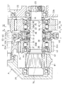
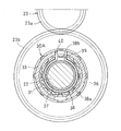
- Sectional drawing of the vehicle motor drive device concerning this invention Sectional drawing which expands and shows the principal part of the transmission of FIG. Sectional view along line IV-IV in FIG. Sectional view along line VV in FIG. Sectional view showing the gear change actuator Sectional view along line VII-VII in FIG. Sectional drawing which expands and shows a part of FIG. Sectional view showing the shift switching state
- An exploded perspective view showing each of the inner ring, the cage, the washer, the switch spring, the elastic member of the speed change actuator, and the friction plate of the 2-way roller clutch.
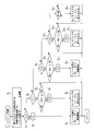
- FIG. 2 is a block diagram of an electronic control device that controls the vehicle motor drive device shown in FIG.
- the flowchart which shows the control at the time of the upshift of the electronic controller shown in FIG.
- the flowchart which shows the control at the time of downshift of the electronic controller shown in FIG. (A) is a diagram showing a correspondence relationship between the shift position at the time of upshifting, the motor torque, and the rotational speed of the input / output member of the two-way roller clutch of the next shift stage, and (B) is the shift at the time of downshifting.
- the figure which shows the correspondence of a position, a motor torque, and the rotational speed of the input / output member of the 2 way roller clutch of the next gear stage.
- FIG. 1 (A) shows an electric vehicle EV in which a pair of left and right front wheels 1 are driven by a motor driving device A according to the present invention.
- FIG. 1B shows a hybrid vehicle HV in which the engine E drives the front wheels 1 as a pair of left and right drive wheels, and the motor drive device A drives the rear wheels 2 as a pair of left and right auxiliary drive wheels.
- the rotation of the engine E is transmitted to the front wheels 1 via the transmission T and the differential gear D.
- the motor drive device A converts the electric motor 10, the transmission 20 that shifts the rotation of the output shaft 11 of the electric motor 10, and the motive power output from the transmission 20, as shown in FIG.
- a differential gear 80 that distributes to the pair of left and right front wheels 1 of the electric vehicle EV shown in A) or distributes to the pair of left and right rear wheels 2 of the hybrid vehicle HV shown in FIG.
- the transmission 20 is composed of a constantly meshing reduction gear in which a first reduction gear train 23 and a second reduction gear train 24 are provided between the first shaft 21 and the second shaft 22.
- the first shaft 21 and the second shaft 22 are rotatably supported by a pair of opposed bearings 26 incorporated in the housing 25 and arranged in parallel.
- the first shaft 21 is connected to the output shaft 11 of the electric motor 10. It is connected.
- the first reduction gear train 23 is provided with a first input gear 23 a on the first shaft 21, and a first output gear 23 b meshing with the first input gear 23 a is rotatable around the second shaft 22.
- the second reduction gear train 24 is provided with a second input gear 24 a on the first shaft 21, and a second output gear 24 b meshing with the second input gear 24 a is rotatable around the second shaft 22.
- the reduction ratio of the second reduction gear train 24 is smaller than the reduction ratio of the first reduction gear train 23.
- a first two-way roller clutch that fastens and releases the first output gear 23 b and the second shaft 22 between the first output gear 23 b and the second shaft 22.
- 30A is incorporated.
- a second two-way roller clutch 30B for fastening and releasing the second output gear 24b and the second shaft 22 is incorporated between the second output gear 24b and the second shaft 22.
- first two-way roller clutch 30A and the second two-way roller clutch 30B have the same configuration and are symmetric, the first two-way roller clutch 30A is described below.
- the second 2-way roller clutch 30B will be described with the same reference numerals assigned to the same components, and the description thereof will be omitted.
- the first two-way roller clutch 30 prevents the inner ring 31 from being engaged with the second shaft 22 by fitting with a spline 32, and a cylindrical surface 33 formed on the outer periphery of the inner ring 31 on the inner periphery of the first output gear 23b.
- a plurality of flat cam surfaces 34 that form a wedge-shaped space whose both ends in the circumferential direction are narrow in the circumferential direction are provided at equal intervals in the circumferential direction, and a roller 35 is incorporated between each cam surface 34 and the cylindrical surface 33. 35 is held by a retainer 36 incorporated between the first output gear 23 b and the inner ring 31.
- a circular recess 37 is formed on one end surface of the inner ring 31 in the axial direction
- a circular portion 38a of the switch spring 38 is fitted in the recess 37, and a pair provided outward from both ends of the circular portion 38a.
- the pressing piece 38b is inserted into a notch 40 formed on one end surface of the retainer 36 from a notch 39 formed on the outer peripheral wall of the recess 37, and the notch 39 and the notch are formed by the pair of engaging pieces 38b.
- the retainer 36 is elastically held at a neutral position where the roller 35 is pressed against the cylindrical surface 33 and the cam surface 34 by pressing opposite end faces in the circumferential direction 40 in opposite directions.
- the inner ring 31 incorporated inside the first output gear 23b and the inner ring 31 incorporated inside the second output gear 24b are composed of a spacer 41 as a rotating member incorporated between the opposing portions, A pair of stopper rings 44 fitted to the two shafts 22 are sandwiched from both sides to be non-movable in the axial direction.
- the spacer 41 rotates integrally with each of the pair of opposed inner rings 31.
- a cylindrical bearing fitting surface 42 is formed on the outer end facing the stopper ring 44 in the pair of inner rings 31, and the first output gear 23 b and the bearing 43 fitted to the bearing fitting surface 42 are used.
- the second output gear 24 b is rotatably supported with respect to the inner ring 31.
- the shift switching actuator 50 is fitted to a control ring 51 that is movable in the axial direction on the outer periphery of the spacer 41 and rotatably supports the pair of friction plates 52 a and 52 b disposed on both sides of the control ring 51.
- One is locked to the retainer 36 of the first 2-way roller clutch 30A, and the other is locked to the retainer 36 of the second 2-way roller clutch 30B, and the control ring 51 is
- the retainer 36 is connected to the first output gear 23b by the friction engagement of the friction plate 52a that is moved toward the one output gear 23b and pressed against the side surface of the first output gear 23b.
- the roller 35 is engaged with the cylindrical surface 33 and the cam surface 34 by relative rotation.
- control mechanism 51 is moved toward the second output gear 24b by the shift mechanism 60, and the retainer 36 is moved to the second output gear 24b by the friction engagement of the friction plate 52b pressed against the side surface of the second output gear 24b.
- the roller 35 is engaged with the cylindrical surface 33 and the cam surface 34 by the relative rotation of the retainer 36 and the inner ring 31.
- the pair of friction plates 52a and 52b are formed in an annular shape, and an L-shaped engagement piece 53 formed on the inner diameter surface of the friction plates 52a and 52b is engaged with the notch portion 40 formed in the retainer 36, thereby the friction plate 52a. , 52b are locked to the retainer 36.
- a washer 54 and an elastic member 55 are incorporated between the opposing surfaces of the engagement piece 53 and the inner ring 31, and the friction plates 52 a and 52 b are attached to the engagement release positions that are separated from the inner ring 31 by the elastic member 55. It is fast.
- an engagement groove 57 is formed at the inner end of the engagement piece 53, while a plurality of engagement protrusions 58 that form engagement means 56 with the engagement groove 57 are formed on the outer periphery of the spacer 41.
- the shift mechanism 60 slidably supports a shift rod 61 arranged parallel to the second shaft 22 by a pair of sliding bearings 62 attached to the housing 25, and shifts to the shift rod 61.
- a fork 63 is attached, and on the other hand, a sleeve 65 is rotatably supported by a rolling bearing 64 fitted to the outer periphery of the control ring 51 and is supported in a non-movable manner in the axial direction.
- the bifurcated piece 63a at the tip of the shift fork 63 is fitted into the annular groove 66, the shift rod 61 is moved in the axial direction by the actuator 67, and the control ring 51 is moved in the axial direction together with the sleeve 65. I have to.
- a cylinder or a solenoid connected to the shift rod 61 can be used as the actuator 67.
- a motor 68 is used, and the rotation of the output shaft 69 of the motor 68 is rotated by the motion conversion mechanism 70. It is converted to movement in the axial direction.
- a drive gear 71 provided on the output shaft 69 of the motor 68 is engaged with a driven gear 72 as a nut member, and the driven gear 72 is rotatably supported by a pair of opposed bearings 73.
- the internal thread 74 formed on the circumference is screw-engaged with the external thread 75 formed on the outer periphery of the end of the shift rod 61, and the shift rod 61 is moved in the axial direction by the rotation of the driven gear 72 at a fixed position. ing.
- an output gear 76 that transmits the rotation of the second shaft 22 to the differential gear 80 is provided at the shaft end of the second shaft 22.
- a ring gear 81 that meshes with the output gear 76 is attached to a differential case 82 that is rotatably supported by the housing 25, and a pair of pinions 84 is mounted on a pinion shaft 83 that is rotatably supported at both ends by the differential case 82.
- a pair of side gears 85 are engaged with each of the pair of pinions 84, and a shaft end portion of the axle 86 is connected to each of the pair of side gears 85.
- the rotation of the electric motor 10 is controlled by a control signal output from the electronic control unit 90 shown in FIG.
- the electronic control device 90 receives a detection signal indicating the rotation speed of the first shaft 21 from the first shaft rotation sensor 91, and a detection signal indicating the rotation speed of the second shaft 22 from the second shaft rotation sensor 92.
- a detection signal indicating the position of the shift fork 63 is input from 93.
- An example of the shift position sensor 93 is a potentiometer connected to the shift rod 61.
- a control signal for controlling the rotation of the motor 68 is output from the electronic control unit 90.
- the vehicle motor drive device A shown in the embodiment has the above-described structure, and FIG. 3 shows that the pair of friction plates 52a and 52b are held at the disengagement positions where they are separated from the first output gear 23b and the second output gear 24b.
- each of the friction plates 52a and 52b that are prevented from rotating by the cage 36 is prevented from rotating with respect to the inner ring 31 by engaging with the engaging groove 57 and the engaging protrusion 58, so It is in a state of being prevented from rotating with respect to the inner ring 31. Therefore, the drag torque acting on the roller 35 does not cause the inner ring 31 and the retainer 36 to rotate relative to each other, and the first and second two-way roller clutches 30A and 30B are erroneously engaged. There is no occurrence.
- the shift rod 61 is moved rightward by driving the motor 68 shown in FIG.
- the sleeve 65 and the control ring 51 are moved in the same direction as the shift rod 61 by 63, and the friction plate 52a is pressed against the side surface of the first output gear 23b by the control ring 51.
- the retainer 36 of the first two-way roller clutch 30A rotates relative to the inner ring 31, the roller 35 engages with the cylindrical surface 33 and the cam surface 34, and the rotation of the first output gear 23b 1 is immediately transmitted to the second shaft 22 via the two-way roller clutch 30A. Further, the rotation of the second shaft 22 is transmitted to the axle 86 through the differential gear 80.
- the switch spring 38 is elastically deformed. Therefore, the motor 68 is rotated in the reverse direction, the shift rod 61 is moved in the reverse direction (the left direction in FIG. 6), and the control ring 51 is moved away from the first output gear 23b. Then, the friction plate 52a is separated from the first output gear 23b by the restoring elasticity of the elastic member 55, and at the same time, the cage 36 is returned and rotated by the restoring elasticity of the switch spring 38, and the roller 35 is returned to the neutral position. Thus, the rotation transmission from the first shaft 21 to the second shaft 22 is immediately interrupted.
- the retainer 36 of the second 2-way roller clutch 30B rotates relative to the inner ring 31, the roller 35 engages with the cylindrical surface 33 and the cam surface 34, and the rotation of the second output gear 24b 2 is immediately transmitted to the second shaft 22 via the 2-way roller clutch 30B, and the torque transmission path is immediately switched.
- the electronic control unit 90 controls the operation of the electric motor 10 and the shift switching actuator 50, and when this control releases the two-way roller clutch 30A, The torque transmitted between the output gear 23b and the inner ring 31 is once reduced to zero.
- shift position the position SP of the shift fork 63 (hereinafter referred to as “shift position”) is changed to the shift position SP of the current shift stage. 1 is moved toward the neutral position SP N (steps S 2 to S 4 , time t 0 in FIG. 14A).
- the shift position SP 1 of the current gear position the friction plate 52a is positioned to frictionally engage the side surface of the first output gear 23b.
- the neutral position SP N is the position SP 1 where the friction plates 52a will frictionally engage the side surface of the first output gear 23b, just the friction plate 52b is located at the position SP 2 to frictionally engage the side surface of the second output gear 24b Intermediate position.
- the difference between the current shift position SP and the neutral position SP N is whether or not a determination whether a preset threshold value DSP 1 below (step S 5, S 6).
- T 1 is the motor torque during normal running, a positive value.
- T 2 is a negative value and is a braking torque that decelerates the electric motor 10.
- the two-way roller clutch 30A is disengaged and the electric motor 10 is quickly decelerated.
- the electric motor 10 can control the motor torque by the applied current, and can decelerate in a much shorter time than the engine.
- the rotational speed N Gi of the second output gear 24b decelerates in conjunction with the electric motor 10, but the rotational speed N Go of the inner ring 31 is maintained substantially constant due to the inertia of the vehicle. Shift position SP, after reaching the neutral position SP N, it retains its state.
- step S 9 and S 10 After starting the control to reduce the motor torque T 2, and the rotational speed N Gi of the second output gear 24b, the speed difference between the rotational speed N Go of the inner ring 31, the first threshold value DN 1 below a preset Is determined (steps S 9 and S 10 ).
- step S 14 when the speed difference between the rotational speed N Gi of the second output gear 24b and the rotational speed N Go of the inner ring 31 is equal to or smaller than a preset second threshold value DN 2 ( ⁇ DN 1 ) (step S). 13, S 14), since the two-way roller clutch 30B of the next shift stage is considered to have sufficient synchro to engage, the motor torque of the electric motor 10 is changed from T 2 to T 3, the electric motor 10 inertia Rotate (steps S 15 and S 16 , time t 3 in FIG. 14A).
- the size of T 3 is substantially zero.
- the zero does not need to be zero in a strict sense, and is zero in a sense that allows a small torque that allows the two-way roller clutch 30A to be disengaged by the elastic restoring force of the switch spring 38. .
- Shift position SP is, close to the shift position SP 2 of next shift stage, the friction plates 52b is in contact with the second output gear 24b, 2-way roller clutch 30B is engaged, the rotational speed N Gi of the second output gear 24b
- the rotational speed N Go of the inner ring 31 matches (time t 4 in FIG. 14A).
- the motor torque of the electric motor 10 is increased from T 3 to T 4, starts driving the next shift stage (step S 17, S 18, FIG. 14 (A), time t 5 ).
- time loss torque of the transmission switching time is the time between times t 1 ⁇ t 5 in FIG. 14 (A). For this reason, the motor torque during the time t 0 to t 1 is maintained compared to the control for reducing the motor torque of the electric motor 10 at the same time that the shift switching command is received. .
- Step S 25 and S 26 While the shift fork 63 is moved toward the neutral position SP N, the difference between the current shift position SP and the neutral position SP N is whether or not a determination whether a preset threshold value DSP 2 below (Steps S 25 and S 26 ).
- T 1 is the motor torque during normal running, a positive value.
- the size of the T 2 are, is approximately zero. The zero here does not need to be zero in a strict sense, and is zero in a sense that allows a minute torque that allows the two-way roller clutch 30B to be disengaged by the elastic restoring force of the switch spring 38. .
- step S 33 and S 34 After starting the control to increase the motor torque to T 3, and the rotational speed N Gi of the first output gear 23b, whether the speed difference between the rotational speed N Go of the inner ring 31 is first threshold value DN 1 below Is determined (steps S 33 and S 34 ).
- step S 37 and S 38 when the speed difference between the rotational speed N Gi of the first output gear 23b and the rotational speed N Go of the inner ring 31 becomes equal to or smaller than the second threshold value DN 2 (steps S 37 and S 38 ), 2 since way roller clutch 30A is considered to have sufficient synchro to engage, the motor torque of the electric motor 10 is changed from T 3 to T 4, the electric motor 10 to inertia rotation (step S 39, S 40, Time t 4 in FIG.
- the size of the T 4 is substantially zero.
- Shift position SP is, close to the shift position SP 1 of the next shift stage, the friction plates 52a contacts the first output gear 23b, 2-way roller clutch 30A is engaged, the rotational speed N Gi of the first output gear 23b
- the rotational speed N Go of the inner ring 31 matches (time t 5 in FIG. 14B).
- the motor torque of the electric motor 10 is increased from T 4 to T 5, starts driving the next shift stage (step S 41, S 42, FIG. 14 (B), time t 6 ).
- the torque loss time at the time of shifting is the time between times t 1 and t 6 in FIG. 14B. For this reason, the motor torque during the time t 0 to t 1 is maintained compared to the control for reducing the motor torque of the electric motor 10 at the same time that the shift switching command is received. .
- the motor torque of the electric motor 10 is maintained and torque loss does not occur until the electronic control unit 90 determines that the friction plates 52a and 52b are separated. For this reason, it is possible to suppress the torque loss time at the time of shift switching, compared to the control in which the motor torque becomes zero simultaneously with the start of operation of the shift switching actuator 50.
- the first 2-way roller clutch 30A or the second 2-way roller clutch 30B is immediately engaged and engaged. Since the engagement is released, the shift can be switched quickly.
- a control ring 51 and two friction plates 52a and 52b are incorporated between the first output gear 23b and the second output gear 24b, and one friction plate 52a is connected to the first two-way roller clutch 30A.
- the other friction plate 52b is prevented from rotating around the retainer 36 of the second two-way roller clutch 30B so that the control ring 51 can be shifted in the left-right direction by the shift mechanism 60, If it is configured such that engagement and release of the two sets of the two-way roller clutches 30A and 30B can be controlled by one shift switching actuator 50, the motor drive device can be reduced in size.
- the friction plates 52a and 52b are smoothly rotated relative to the control ring 51 when the friction plates 52a and 52b are pressed against the first output gear 23b and the second output gear 24b to be frictionally engaged.
- the two-way roller clutches 30A and 30B can be reliably engaged.
- the cylindrical surface 33 is formed on the inner periphery of the first output gear 23b and the second output gear 24b, and the cam surface 34 is provided on the outer periphery of the inner ring 31 incorporated inside each output gear 23b, 24b.
- cam surfaces may be formed on the inner periphery of the first output gear 23b and the second output gear 24b, and a cylindrical surface may be provided on the outer periphery of the inner ring.
- a cage is incorporated between the first output gear 23b and the second output gear 24b and the cage 36 to elastically hold the cage so that the roller is in a neutral state.
Priority Applications (3)
| Application Number | Priority Date | Filing Date | Title |
|---|---|---|---|
| US13/393,561 US9102226B2 (en) | 2009-09-08 | 2010-08-26 | Motor drive apparatus for vehicle and motor vehicle |
| CN201080039550.4A CN102483135B (zh) | 2009-09-08 | 2010-08-26 | 车辆用马达驱动装置以及汽车 |
| EP10815267.9A EP2476932B1 (en) | 2009-09-08 | 2010-08-26 | Motor drive device for vehicle, and automobile |
Applications Claiming Priority (4)
| Application Number | Priority Date | Filing Date | Title |
|---|---|---|---|
| JP2009207123A JP5474456B2 (ja) | 2009-09-08 | 2009-09-08 | 車両用モータ駆動装置および自動車 |
| JP2009-207123 | 2009-09-08 | ||
| JP2009207191A JP5387967B2 (ja) | 2009-09-08 | 2009-09-08 | 車両用モータ駆動装置および自動車 |
| JP2009-207191 | 2009-09-08 |
Publications (1)
| Publication Number | Publication Date |
|---|---|
| WO2011030670A1 true WO2011030670A1 (ja) | 2011-03-17 |
Family
ID=43732344
Family Applications (1)
| Application Number | Title | Priority Date | Filing Date |
|---|---|---|---|
| PCT/JP2010/064442 WO2011030670A1 (ja) | 2009-09-08 | 2010-08-26 | 車両用モータ駆動装置および自動車 |
Country Status (4)
| Country | Link |
|---|---|
| US (1) | US9102226B2 (zh) |
| EP (1) | EP2476932B1 (zh) |
| CN (1) | CN102483135B (zh) |
| WO (1) | WO2011030670A1 (zh) |
Cited By (5)
| Publication number | Priority date | Publication date | Assignee | Title |
|---|---|---|---|---|
| WO2012128020A1 (ja) * | 2011-03-18 | 2012-09-27 | Ntn株式会社 | 車両用モータ駆動装置および自動車 |
| WO2012137812A1 (ja) * | 2011-04-05 | 2012-10-11 | Ntn株式会社 | 車両用モータ駆動装置および自動車 |
| WO2013030297A3 (de) * | 2011-09-02 | 2014-04-24 | Cpm Compact Power Motors Gmbh | Elektrisches antriebssystem für ein batteriegetriebenes leichtfahrzeug |
| CN103782061A (zh) * | 2011-09-13 | 2014-05-07 | Ntn株式会社 | 车辆用电动机驱动装置以及汽车 |
| CN104054241A (zh) * | 2012-02-24 | 2014-09-17 | Ntn株式会社 | 车辆用马达驱动装置 |
Families Citing this family (24)
| Publication number | Priority date | Publication date | Assignee | Title |
|---|---|---|---|---|
| US9242544B2 (en) * | 2011-09-23 | 2016-01-26 | Kanzaki Kokyukoki Mfg. Co., Ltd. | Vehicle with electric transaxle |
| US8936120B2 (en) * | 2011-12-29 | 2015-01-20 | Kawasaki Jukogyo Kabushiki Kaisha | Utility vehicle having a front electric motor |
| ES2660552T3 (es) * | 2012-09-06 | 2018-03-22 | Iveco S.P.A. | Vehículo que comprende un distribuidor de torque para dos ejes, método para controlar el mismo, programa informático y medios que pueden ser leídos por una computadora |
| US9033839B2 (en) * | 2012-11-12 | 2015-05-19 | Magna E-Car Systems Of America, Inc. | Direct drive transmission decoupler |
| DE102014201352A1 (de) * | 2014-01-27 | 2015-01-08 | Schaeffler Technologies Gmbh & Co. Kg | Antriebsanordnung für ein Kraftfahrzeug |
| US9882447B2 (en) | 2015-06-09 | 2018-01-30 | Regal Beloit America, Inc. | Electric machine, assembly and associated method |
| CN107810347B (zh) * | 2015-06-25 | 2021-09-21 | 博格华纳瑞典公司 | 变速箱 |
| CN105526280B (zh) * | 2016-01-19 | 2017-12-29 | 北京工业大学 | 双向非逆止超越离合器 |
| JP6396942B2 (ja) * | 2016-04-26 | 2018-09-26 | 本田技研工業株式会社 | 変速機の制御装置 |
| CN113815393A (zh) | 2016-05-06 | 2021-12-21 | 艾里逊变速箱公司 | 具有电动机的车桥总成 |
| FR3053007B1 (fr) * | 2016-06-28 | 2019-08-23 | France Reducteurs | Transmission, notamment pour engin roulant, et engin roulant equipe d'une telle transmission |
| CN106864228A (zh) * | 2017-02-24 | 2017-06-20 | 重庆康昌机械制造有限公司 | 电机驱动的底盘传动结构 |
| JP6827364B2 (ja) * | 2017-05-01 | 2021-02-10 | 株式会社クボタ | 多目的車両 |
| TWI655116B (zh) * | 2017-05-19 | 2019-04-01 | 財團法人工業技術研究院 | 一種傳動機構及其應用之單向組件 |
| CN107100963B (zh) * | 2017-06-02 | 2023-02-28 | 重庆隆旺机电有限责任公司 | 多功能变速器总成 |
| CN207261604U (zh) * | 2017-08-31 | 2018-04-20 | 东风德纳车桥有限公司 | 一种差速换挡总成 |
| CN112776580A (zh) * | 2017-09-20 | 2021-05-11 | 丰田自动车株式会社 | 电动车辆 |
| USD927578S1 (en) | 2018-09-27 | 2021-08-10 | Allison Transmission, Inc. | Axle assembly |
| DE102018009582A1 (de) * | 2018-12-05 | 2020-06-10 | Daimler Ag | Elektrischer Achsantrieb für ein Nutzfahrzeug |
| DE102019003004A1 (de) * | 2019-04-25 | 2020-10-29 | Borgwarner Inc. | Getriebe für den Antriebsstrang eines Elektro- oder Hybridfahrzeugs, Antriebsstrang und Verfahren zum Betrieb eines solchen Antriebsstrangs |
| CN110985614B (zh) * | 2019-12-04 | 2023-09-05 | 西南大学 | 带有传动传感功能的自适应自动变速总成 |
| CN111577842B (zh) * | 2020-05-13 | 2024-04-05 | 北京开云汽车有限公司 | 一种湿式单离合两挡变速器 |
| CN112283264B (zh) * | 2020-10-20 | 2023-08-25 | 深圳职业技术学院 | 双向超越离合器 |
| CN113323971B (zh) * | 2021-06-01 | 2022-09-02 | 周旭亮 | 联动双向超越离合器式无缝换挡机构 |
Citations (6)
| Publication number | Priority date | Publication date | Assignee | Title |
|---|---|---|---|---|
| JPH06179326A (ja) * | 1992-12-14 | 1994-06-28 | Aqueous Res:Kk | 車輌における動力伝達装置 |
| JP2004211834A (ja) * | 2003-01-07 | 2004-07-29 | Jatco Ltd | 多段変速機及びその変速制御装置 |
| JP2004316825A (ja) * | 2003-04-17 | 2004-11-11 | Jatco Ltd | 多段変速機 |
| JP3683405B2 (ja) | 1998-02-24 | 2005-08-17 | 本田技研工業株式会社 | 車両の発進アシスト装置 |
| JP2006112489A (ja) | 2004-10-13 | 2006-04-27 | Toyota Motor Corp | 駆動装置 |
| JP2008045601A (ja) * | 2006-08-11 | 2008-02-28 | Hitachi Ltd | 動力伝達装置 |
Family Cites Families (5)
| Publication number | Priority date | Publication date | Assignee | Title |
|---|---|---|---|---|
| US4817451A (en) | 1987-02-26 | 1989-04-04 | Weismann Peter H | Control mechanism for selective engagement of a free wheeling engagement mechanism |
| US5224393A (en) | 1990-05-11 | 1993-07-06 | Honda Giken Kogyo Kabushiki Kaisha | Electronically controlled transmission and steering wheel located shift mechanism |
| US6427547B1 (en) | 2001-02-08 | 2002-08-06 | New Venture Gear, Inc. | Dual-countershaft twin-clutch automated transmission with bi-directional clutches |
| US6817457B2 (en) * | 2001-07-26 | 2004-11-16 | Ntn Corporation | Two-way roller clutch with torque limiting feature |
| EP1519084A3 (en) | 2003-09-26 | 2012-05-02 | NTN Corporation | Vehicle transmission |
-
2010
- 2010-08-26 WO PCT/JP2010/064442 patent/WO2011030670A1/ja active Application Filing
- 2010-08-26 CN CN201080039550.4A patent/CN102483135B/zh not_active Expired - Fee Related
- 2010-08-26 US US13/393,561 patent/US9102226B2/en active Active
- 2010-08-26 EP EP10815267.9A patent/EP2476932B1/en not_active Not-in-force
Patent Citations (6)
| Publication number | Priority date | Publication date | Assignee | Title |
|---|---|---|---|---|
| JPH06179326A (ja) * | 1992-12-14 | 1994-06-28 | Aqueous Res:Kk | 車輌における動力伝達装置 |
| JP3683405B2 (ja) | 1998-02-24 | 2005-08-17 | 本田技研工業株式会社 | 車両の発進アシスト装置 |
| JP2004211834A (ja) * | 2003-01-07 | 2004-07-29 | Jatco Ltd | 多段変速機及びその変速制御装置 |
| JP2004316825A (ja) * | 2003-04-17 | 2004-11-11 | Jatco Ltd | 多段変速機 |
| JP2006112489A (ja) | 2004-10-13 | 2006-04-27 | Toyota Motor Corp | 駆動装置 |
| JP2008045601A (ja) * | 2006-08-11 | 2008-02-28 | Hitachi Ltd | 動力伝達装置 |
Non-Patent Citations (1)
| Title |
|---|
| See also references of EP2476932A4 |
Cited By (7)
| Publication number | Priority date | Publication date | Assignee | Title |
|---|---|---|---|---|
| WO2012128020A1 (ja) * | 2011-03-18 | 2012-09-27 | Ntn株式会社 | 車両用モータ駆動装置および自動車 |
| WO2012137812A1 (ja) * | 2011-04-05 | 2012-10-11 | Ntn株式会社 | 車両用モータ駆動装置および自動車 |
| WO2013030297A3 (de) * | 2011-09-02 | 2014-04-24 | Cpm Compact Power Motors Gmbh | Elektrisches antriebssystem für ein batteriegetriebenes leichtfahrzeug |
| CN103782061A (zh) * | 2011-09-13 | 2014-05-07 | Ntn株式会社 | 车辆用电动机驱动装置以及汽车 |
| CN104054241A (zh) * | 2012-02-24 | 2014-09-17 | Ntn株式会社 | 车辆用马达驱动装置 |
| US20150038277A1 (en) * | 2012-02-24 | 2015-02-05 | Ntn Corporation | Motor drive assembly for a vehicle |
| US9130412B2 (en) * | 2012-02-24 | 2015-09-08 | Ntn Corporation | Motor drive assembly for a vehicle |
Also Published As
| Publication number | Publication date |
|---|---|
| EP2476932A4 (en) | 2014-04-02 |
| EP2476932B1 (en) | 2016-11-16 |
| CN102483135A (zh) | 2012-05-30 |
| US20120158233A1 (en) | 2012-06-21 |
| EP2476932A1 (en) | 2012-07-18 |
| CN102483135B (zh) | 2016-01-20 |
| US9102226B2 (en) | 2015-08-11 |
Similar Documents
| Publication | Publication Date | Title |
|---|---|---|
| WO2011030670A1 (ja) | 車両用モータ駆動装置および自動車 | |
| JP5580217B2 (ja) | 車両用モータ駆動装置および自動車 | |
| JP5465614B2 (ja) | 車両用モータ駆動装置および自動車 | |
| JP5822615B2 (ja) | 自動クラッチ制御装置およびその変速制御方法 | |
| WO2011037023A1 (ja) | 車両用電動モータ駆動装置 | |
| EP2738421B1 (en) | Transmission and electric vehicle comprising same | |
| JP5387967B2 (ja) | 車両用モータ駆動装置および自動車 | |
| WO2012165146A1 (ja) | 車両用モータ駆動装置の変速制御方法および自動車の変速制御方法 | |
| JP5474456B2 (ja) | 車両用モータ駆動装置および自動車 | |
| US20140076080A1 (en) | Transmission | |
| JP2013130266A (ja) | 車両用モータ駆動装置 | |
| WO2013176074A1 (ja) | 電気自動車の変速制御方法および変速制御装置 | |
| JP2013087778A (ja) | デュアルクラッチ式自動変速機およびその変速制御方法 | |
| JP2014031857A (ja) | 多軸変速機 | |
| JP2014047817A (ja) | 電気自動車の変速制御方法および変速制御装置 | |
| JP2014001746A (ja) | 電気自動車の変速制御方法および変速制御装置 | |
| JP7422938B2 (ja) | 変速機 | |
| WO2023026399A1 (ja) | パーキング機構 | |
| WO2013183482A1 (ja) | 電気自動車の変速制御方法および変速制御装置 | |
| JP6023505B2 (ja) | 変速機 | |
| JP6052133B2 (ja) | 変速機のシフト機構 | |
| JP6178745B2 (ja) | 動力伝達装置 | |
| JPH08184373A (ja) | 変速機のギヤ抜け防止装置 | |
| JP2014035021A (ja) | 変速機 | |
| JP2014145416A (ja) | クラッチ装置 |
Legal Events
| Date | Code | Title | Description |
|---|---|---|---|
| WWE | Wipo information: entry into national phase |
Ref document number: 201080039550.4 Country of ref document: CN |
|
| 121 | Ep: the epo has been informed by wipo that ep was designated in this application |
Ref document number: 10815267 Country of ref document: EP Kind code of ref document: A1 |
|
| WWE | Wipo information: entry into national phase |
Ref document number: 13393561 Country of ref document: US |
|
| NENP | Non-entry into the national phase |
Ref country code: DE |
|
| REEP | Request for entry into the european phase |
Ref document number: 2010815267 Country of ref document: EP |
|
| WWE | Wipo information: entry into national phase |
Ref document number: 2010815267 Country of ref document: EP |
|
| WWE | Wipo information: entry into national phase |
Ref document number: 3011/CHENP/2012 Country of ref document: IN |