WO2012137812A1 - 車両用モータ駆動装置および自動車 - Google Patents
車両用モータ駆動装置および自動車 Download PDFInfo
- Publication number
- WO2012137812A1 WO2012137812A1 PCT/JP2012/059174 JP2012059174W WO2012137812A1 WO 2012137812 A1 WO2012137812 A1 WO 2012137812A1 JP 2012059174 W JP2012059174 W JP 2012059174W WO 2012137812 A1 WO2012137812 A1 WO 2012137812A1
- Authority
- WO
- WIPO (PCT)
- Prior art keywords
- speed
- roller
- gear
- clutch
- engagement
- Prior art date
Links
Images


Classifications
-
- F—MECHANICAL ENGINEERING; LIGHTING; HEATING; WEAPONS; BLASTING
- F16—ENGINEERING ELEMENTS AND UNITS; GENERAL MEASURES FOR PRODUCING AND MAINTAINING EFFECTIVE FUNCTIONING OF MACHINES OR INSTALLATIONS; THERMAL INSULATION IN GENERAL
- F16H—GEARING
- F16H3/00—Toothed gearings for conveying rotary motion with variable gear ratio or for reversing rotary motion
- F16H3/02—Toothed gearings for conveying rotary motion with variable gear ratio or for reversing rotary motion without gears having orbital motion
- F16H3/08—Toothed gearings for conveying rotary motion with variable gear ratio or for reversing rotary motion without gears having orbital motion exclusively or essentially with continuously meshing gears, that can be disengaged from their shafts
- F16H3/10—Toothed gearings for conveying rotary motion with variable gear ratio or for reversing rotary motion without gears having orbital motion exclusively or essentially with continuously meshing gears, that can be disengaged from their shafts with one or more one-way clutches as an essential feature
-
- B—PERFORMING OPERATIONS; TRANSPORTING
- B60—VEHICLES IN GENERAL
- B60K—ARRANGEMENT OR MOUNTING OF PROPULSION UNITS OR OF TRANSMISSIONS IN VEHICLES; ARRANGEMENT OR MOUNTING OF PLURAL DIVERSE PRIME-MOVERS IN VEHICLES; AUXILIARY DRIVES FOR VEHICLES; INSTRUMENTATION OR DASHBOARDS FOR VEHICLES; ARRANGEMENTS IN CONNECTION WITH COOLING, AIR INTAKE, GAS EXHAUST OR FUEL SUPPLY OF PROPULSION UNITS IN VEHICLES
- B60K6/00—Arrangement or mounting of plural diverse prime-movers for mutual or common propulsion, e.g. hybrid propulsion systems comprising electric motors and internal combustion engines ; Control systems therefor, i.e. systems controlling two or more prime movers, or controlling one of these prime movers and any of the transmission, drive or drive units Informative references: mechanical gearings with secondary electric drive F16H3/72; arrangements for handling mechanical energy structurally associated with the dynamo-electric machine H02K7/00; machines comprising structurally interrelated motor and generator parts H02K51/00; dynamo-electric machines not otherwise provided for in H02K see H02K99/00
- B60K6/20—Arrangement or mounting of plural diverse prime-movers for mutual or common propulsion, e.g. hybrid propulsion systems comprising electric motors and internal combustion engines ; Control systems therefor, i.e. systems controlling two or more prime movers, or controlling one of these prime movers and any of the transmission, drive or drive units Informative references: mechanical gearings with secondary electric drive F16H3/72; arrangements for handling mechanical energy structurally associated with the dynamo-electric machine H02K7/00; machines comprising structurally interrelated motor and generator parts H02K51/00; dynamo-electric machines not otherwise provided for in H02K see H02K99/00 the prime-movers consisting of electric motors and internal combustion engines, e.g. HEVs
- B60K6/22—Arrangement or mounting of plural diverse prime-movers for mutual or common propulsion, e.g. hybrid propulsion systems comprising electric motors and internal combustion engines ; Control systems therefor, i.e. systems controlling two or more prime movers, or controlling one of these prime movers and any of the transmission, drive or drive units Informative references: mechanical gearings with secondary electric drive F16H3/72; arrangements for handling mechanical energy structurally associated with the dynamo-electric machine H02K7/00; machines comprising structurally interrelated motor and generator parts H02K51/00; dynamo-electric machines not otherwise provided for in H02K see H02K99/00 the prime-movers consisting of electric motors and internal combustion engines, e.g. HEVs characterised by apparatus, components or means specially adapted for HEVs
- B60K6/36—Arrangement or mounting of plural diverse prime-movers for mutual or common propulsion, e.g. hybrid propulsion systems comprising electric motors and internal combustion engines ; Control systems therefor, i.e. systems controlling two or more prime movers, or controlling one of these prime movers and any of the transmission, drive or drive units Informative references: mechanical gearings with secondary electric drive F16H3/72; arrangements for handling mechanical energy structurally associated with the dynamo-electric machine H02K7/00; machines comprising structurally interrelated motor and generator parts H02K51/00; dynamo-electric machines not otherwise provided for in H02K see H02K99/00 the prime-movers consisting of electric motors and internal combustion engines, e.g. HEVs characterised by apparatus, components or means specially adapted for HEVs characterised by the transmission gearings
-
- B—PERFORMING OPERATIONS; TRANSPORTING
- B60—VEHICLES IN GENERAL
- B60K—ARRANGEMENT OR MOUNTING OF PROPULSION UNITS OR OF TRANSMISSIONS IN VEHICLES; ARRANGEMENT OR MOUNTING OF PLURAL DIVERSE PRIME-MOVERS IN VEHICLES; AUXILIARY DRIVES FOR VEHICLES; INSTRUMENTATION OR DASHBOARDS FOR VEHICLES; ARRANGEMENTS IN CONNECTION WITH COOLING, AIR INTAKE, GAS EXHAUST OR FUEL SUPPLY OF PROPULSION UNITS IN VEHICLES
- B60K6/00—Arrangement or mounting of plural diverse prime-movers for mutual or common propulsion, e.g. hybrid propulsion systems comprising electric motors and internal combustion engines ; Control systems therefor, i.e. systems controlling two or more prime movers, or controlling one of these prime movers and any of the transmission, drive or drive units Informative references: mechanical gearings with secondary electric drive F16H3/72; arrangements for handling mechanical energy structurally associated with the dynamo-electric machine H02K7/00; machines comprising structurally interrelated motor and generator parts H02K51/00; dynamo-electric machines not otherwise provided for in H02K see H02K99/00
- B60K6/20—Arrangement or mounting of plural diverse prime-movers for mutual or common propulsion, e.g. hybrid propulsion systems comprising electric motors and internal combustion engines ; Control systems therefor, i.e. systems controlling two or more prime movers, or controlling one of these prime movers and any of the transmission, drive or drive units Informative references: mechanical gearings with secondary electric drive F16H3/72; arrangements for handling mechanical energy structurally associated with the dynamo-electric machine H02K7/00; machines comprising structurally interrelated motor and generator parts H02K51/00; dynamo-electric machines not otherwise provided for in H02K see H02K99/00 the prime-movers consisting of electric motors and internal combustion engines, e.g. HEVs
- B60K6/22—Arrangement or mounting of plural diverse prime-movers for mutual or common propulsion, e.g. hybrid propulsion systems comprising electric motors and internal combustion engines ; Control systems therefor, i.e. systems controlling two or more prime movers, or controlling one of these prime movers and any of the transmission, drive or drive units Informative references: mechanical gearings with secondary electric drive F16H3/72; arrangements for handling mechanical energy structurally associated with the dynamo-electric machine H02K7/00; machines comprising structurally interrelated motor and generator parts H02K51/00; dynamo-electric machines not otherwise provided for in H02K see H02K99/00 the prime-movers consisting of electric motors and internal combustion engines, e.g. HEVs characterised by apparatus, components or means specially adapted for HEVs
- B60K6/38—Arrangement or mounting of plural diverse prime-movers for mutual or common propulsion, e.g. hybrid propulsion systems comprising electric motors and internal combustion engines ; Control systems therefor, i.e. systems controlling two or more prime movers, or controlling one of these prime movers and any of the transmission, drive or drive units Informative references: mechanical gearings with secondary electric drive F16H3/72; arrangements for handling mechanical energy structurally associated with the dynamo-electric machine H02K7/00; machines comprising structurally interrelated motor and generator parts H02K51/00; dynamo-electric machines not otherwise provided for in H02K see H02K99/00 the prime-movers consisting of electric motors and internal combustion engines, e.g. HEVs characterised by apparatus, components or means specially adapted for HEVs characterised by the driveline clutches
- B60K6/383—One-way clutches or freewheel devices
-
- B—PERFORMING OPERATIONS; TRANSPORTING
- B60—VEHICLES IN GENERAL
- B60K—ARRANGEMENT OR MOUNTING OF PROPULSION UNITS OR OF TRANSMISSIONS IN VEHICLES; ARRANGEMENT OR MOUNTING OF PLURAL DIVERSE PRIME-MOVERS IN VEHICLES; AUXILIARY DRIVES FOR VEHICLES; INSTRUMENTATION OR DASHBOARDS FOR VEHICLES; ARRANGEMENTS IN CONNECTION WITH COOLING, AIR INTAKE, GAS EXHAUST OR FUEL SUPPLY OF PROPULSION UNITS IN VEHICLES
- B60K6/00—Arrangement or mounting of plural diverse prime-movers for mutual or common propulsion, e.g. hybrid propulsion systems comprising electric motors and internal combustion engines ; Control systems therefor, i.e. systems controlling two or more prime movers, or controlling one of these prime movers and any of the transmission, drive or drive units Informative references: mechanical gearings with secondary electric drive F16H3/72; arrangements for handling mechanical energy structurally associated with the dynamo-electric machine H02K7/00; machines comprising structurally interrelated motor and generator parts H02K51/00; dynamo-electric machines not otherwise provided for in H02K see H02K99/00
- B60K6/20—Arrangement or mounting of plural diverse prime-movers for mutual or common propulsion, e.g. hybrid propulsion systems comprising electric motors and internal combustion engines ; Control systems therefor, i.e. systems controlling two or more prime movers, or controlling one of these prime movers and any of the transmission, drive or drive units Informative references: mechanical gearings with secondary electric drive F16H3/72; arrangements for handling mechanical energy structurally associated with the dynamo-electric machine H02K7/00; machines comprising structurally interrelated motor and generator parts H02K51/00; dynamo-electric machines not otherwise provided for in H02K see H02K99/00 the prime-movers consisting of electric motors and internal combustion engines, e.g. HEVs
- B60K6/42—Arrangement or mounting of plural diverse prime-movers for mutual or common propulsion, e.g. hybrid propulsion systems comprising electric motors and internal combustion engines ; Control systems therefor, i.e. systems controlling two or more prime movers, or controlling one of these prime movers and any of the transmission, drive or drive units Informative references: mechanical gearings with secondary electric drive F16H3/72; arrangements for handling mechanical energy structurally associated with the dynamo-electric machine H02K7/00; machines comprising structurally interrelated motor and generator parts H02K51/00; dynamo-electric machines not otherwise provided for in H02K see H02K99/00 the prime-movers consisting of electric motors and internal combustion engines, e.g. HEVs characterised by the architecture of the hybrid electric vehicle
- B60K6/48—Parallel type
-
- B—PERFORMING OPERATIONS; TRANSPORTING
- B60—VEHICLES IN GENERAL
- B60L—PROPULSION OF ELECTRICALLY-PROPELLED VEHICLES; SUPPLYING ELECTRIC POWER FOR AUXILIARY EQUIPMENT OF ELECTRICALLY-PROPELLED VEHICLES; ELECTRODYNAMIC BRAKE SYSTEMS FOR VEHICLES IN GENERAL; MAGNETIC SUSPENSION OR LEVITATION FOR VEHICLES; MONITORING OPERATING VARIABLES OF ELECTRICALLY-PROPELLED VEHICLES; ELECTRIC SAFETY DEVICES FOR ELECTRICALLY-PROPELLED VEHICLES
- B60L15/00—Methods, circuits, or devices for controlling the traction-motor speed of electrically-propelled vehicles
- B60L15/20—Methods, circuits, or devices for controlling the traction-motor speed of electrically-propelled vehicles for control of the vehicle or its driving motor to achieve a desired performance, e.g. speed, torque, programmed variation of speed
- B60L15/2054—Methods, circuits, or devices for controlling the traction-motor speed of electrically-propelled vehicles for control of the vehicle or its driving motor to achieve a desired performance, e.g. speed, torque, programmed variation of speed by controlling transmissions or clutches
-
- B—PERFORMING OPERATIONS; TRANSPORTING
- B60—VEHICLES IN GENERAL
- B60W—CONJOINT CONTROL OF VEHICLE SUB-UNITS OF DIFFERENT TYPE OR DIFFERENT FUNCTION; CONTROL SYSTEMS SPECIALLY ADAPTED FOR HYBRID VEHICLES; ROAD VEHICLE DRIVE CONTROL SYSTEMS FOR PURPOSES NOT RELATED TO THE CONTROL OF A PARTICULAR SUB-UNIT
- B60W10/00—Conjoint control of vehicle sub-units of different type or different function
- B60W10/04—Conjoint control of vehicle sub-units of different type or different function including control of propulsion units
- B60W10/08—Conjoint control of vehicle sub-units of different type or different function including control of propulsion units including control of electric propulsion units, e.g. motors or generators
-
- B—PERFORMING OPERATIONS; TRANSPORTING
- B60—VEHICLES IN GENERAL
- B60W—CONJOINT CONTROL OF VEHICLE SUB-UNITS OF DIFFERENT TYPE OR DIFFERENT FUNCTION; CONTROL SYSTEMS SPECIALLY ADAPTED FOR HYBRID VEHICLES; ROAD VEHICLE DRIVE CONTROL SYSTEMS FOR PURPOSES NOT RELATED TO THE CONTROL OF A PARTICULAR SUB-UNIT
- B60W30/00—Purposes of road vehicle drive control systems not related to the control of a particular sub-unit, e.g. of systems using conjoint control of vehicle sub-units, or advanced driver assistance systems for ensuring comfort, stability and safety or drive control systems for propelling or retarding the vehicle
- B60W30/18—Propelling the vehicle
- B60W30/20—Reducing vibrations in the driveline
-
- F—MECHANICAL ENGINEERING; LIGHTING; HEATING; WEAPONS; BLASTING
- F16—ENGINEERING ELEMENTS AND UNITS; GENERAL MEASURES FOR PRODUCING AND MAINTAINING EFFECTIVE FUNCTIONING OF MACHINES OR INSTALLATIONS; THERMAL INSULATION IN GENERAL
- F16D—COUPLINGS FOR TRANSMITTING ROTATION; CLUTCHES; BRAKES
- F16D41/00—Freewheels or freewheel clutches
- F16D41/06—Freewheels or freewheel clutches with intermediate wedging coupling members between an inner and an outer surface
- F16D41/08—Freewheels or freewheel clutches with intermediate wedging coupling members between an inner and an outer surface with provision for altering the freewheeling action
- F16D41/10—Freewheels or freewheel clutches with intermediate wedging coupling members between an inner and an outer surface with provision for altering the freewheeling action with self-actuated reversing
- F16D41/105—Freewheels or freewheel clutches with intermediate wedging coupling members between an inner and an outer surface with provision for altering the freewheeling action with self-actuated reversing the intermediate members being of circular cross-section, of only one size and wedging by rolling movement not having an axial component between inner and outer races, one of which is cylindrical
-
- B—PERFORMING OPERATIONS; TRANSPORTING
- B60—VEHICLES IN GENERAL
- B60L—PROPULSION OF ELECTRICALLY-PROPELLED VEHICLES; SUPPLYING ELECTRIC POWER FOR AUXILIARY EQUIPMENT OF ELECTRICALLY-PROPELLED VEHICLES; ELECTRODYNAMIC BRAKE SYSTEMS FOR VEHICLES IN GENERAL; MAGNETIC SUSPENSION OR LEVITATION FOR VEHICLES; MONITORING OPERATING VARIABLES OF ELECTRICALLY-PROPELLED VEHICLES; ELECTRIC SAFETY DEVICES FOR ELECTRICALLY-PROPELLED VEHICLES
- B60L2270/00—Problem solutions or means not otherwise provided for
- B60L2270/10—Emission reduction
- B60L2270/14—Emission reduction of noise
- B60L2270/142—Emission reduction of noise acoustic
-
- B—PERFORMING OPERATIONS; TRANSPORTING
- B60—VEHICLES IN GENERAL
- B60L—PROPULSION OF ELECTRICALLY-PROPELLED VEHICLES; SUPPLYING ELECTRIC POWER FOR AUXILIARY EQUIPMENT OF ELECTRICALLY-PROPELLED VEHICLES; ELECTRODYNAMIC BRAKE SYSTEMS FOR VEHICLES IN GENERAL; MAGNETIC SUSPENSION OR LEVITATION FOR VEHICLES; MONITORING OPERATING VARIABLES OF ELECTRICALLY-PROPELLED VEHICLES; ELECTRIC SAFETY DEVICES FOR ELECTRICALLY-PROPELLED VEHICLES
- B60L2270/00—Problem solutions or means not otherwise provided for
- B60L2270/10—Emission reduction
- B60L2270/14—Emission reduction of noise
- B60L2270/145—Structure borne vibrations
-
- B—PERFORMING OPERATIONS; TRANSPORTING
- B60—VEHICLES IN GENERAL
- B60W—CONJOINT CONTROL OF VEHICLE SUB-UNITS OF DIFFERENT TYPE OR DIFFERENT FUNCTION; CONTROL SYSTEMS SPECIALLY ADAPTED FOR HYBRID VEHICLES; ROAD VEHICLE DRIVE CONTROL SYSTEMS FOR PURPOSES NOT RELATED TO THE CONTROL OF A PARTICULAR SUB-UNIT
- B60W2710/00—Output or target parameters relating to a particular sub-units
- B60W2710/08—Electric propulsion units
- B60W2710/083—Torque
-
- F—MECHANICAL ENGINEERING; LIGHTING; HEATING; WEAPONS; BLASTING
- F16—ENGINEERING ELEMENTS AND UNITS; GENERAL MEASURES FOR PRODUCING AND MAINTAINING EFFECTIVE FUNCTIONING OF MACHINES OR INSTALLATIONS; THERMAL INSULATION IN GENERAL
- F16H—GEARING
- F16H2200/00—Transmissions for multiple ratios
- F16H2200/0021—Transmissions for multiple ratios specially adapted for electric vehicles
-
- F—MECHANICAL ENGINEERING; LIGHTING; HEATING; WEAPONS; BLASTING
- F16—ENGINEERING ELEMENTS AND UNITS; GENERAL MEASURES FOR PRODUCING AND MAINTAINING EFFECTIVE FUNCTIONING OF MACHINES OR INSTALLATIONS; THERMAL INSULATION IN GENERAL
- F16H—GEARING
- F16H2200/00—Transmissions for multiple ratios
- F16H2200/003—Transmissions for multiple ratios characterised by the number of forward speeds
- F16H2200/0034—Transmissions for multiple ratios characterised by the number of forward speeds the gear ratios comprising two forward speeds
-
- Y—GENERAL TAGGING OF NEW TECHNOLOGICAL DEVELOPMENTS; GENERAL TAGGING OF CROSS-SECTIONAL TECHNOLOGIES SPANNING OVER SEVERAL SECTIONS OF THE IPC; TECHNICAL SUBJECTS COVERED BY FORMER USPC CROSS-REFERENCE ART COLLECTIONS [XRACs] AND DIGESTS
- Y02—TECHNOLOGIES OR APPLICATIONS FOR MITIGATION OR ADAPTATION AGAINST CLIMATE CHANGE
- Y02T—CLIMATE CHANGE MITIGATION TECHNOLOGIES RELATED TO TRANSPORTATION
- Y02T10/00—Road transport of goods or passengers
- Y02T10/60—Other road transportation technologies with climate change mitigation effect
- Y02T10/62—Hybrid vehicles
-
- Y—GENERAL TAGGING OF NEW TECHNOLOGICAL DEVELOPMENTS; GENERAL TAGGING OF CROSS-SECTIONAL TECHNOLOGIES SPANNING OVER SEVERAL SECTIONS OF THE IPC; TECHNICAL SUBJECTS COVERED BY FORMER USPC CROSS-REFERENCE ART COLLECTIONS [XRACs] AND DIGESTS
- Y02—TECHNOLOGIES OR APPLICATIONS FOR MITIGATION OR ADAPTATION AGAINST CLIMATE CHANGE
- Y02T—CLIMATE CHANGE MITIGATION TECHNOLOGIES RELATED TO TRANSPORTATION
- Y02T10/00—Road transport of goods or passengers
- Y02T10/60—Other road transportation technologies with climate change mitigation effect
- Y02T10/64—Electric machine technologies in electromobility
-
- Y—GENERAL TAGGING OF NEW TECHNOLOGICAL DEVELOPMENTS; GENERAL TAGGING OF CROSS-SECTIONAL TECHNOLOGIES SPANNING OVER SEVERAL SECTIONS OF THE IPC; TECHNICAL SUBJECTS COVERED BY FORMER USPC CROSS-REFERENCE ART COLLECTIONS [XRACs] AND DIGESTS
- Y02—TECHNOLOGIES OR APPLICATIONS FOR MITIGATION OR ADAPTATION AGAINST CLIMATE CHANGE
- Y02T—CLIMATE CHANGE MITIGATION TECHNOLOGIES RELATED TO TRANSPORTATION
- Y02T10/00—Road transport of goods or passengers
- Y02T10/60—Other road transportation technologies with climate change mitigation effect
- Y02T10/72—Electric energy management in electromobility
Definitions
- the present invention relates to a vehicle motor drive device that shifts the rotation of an electric motor and transmits it to wheels, and an automobile equipped with the motor drive device.
- An electric motor, a transmission that changes the rotation of the electric motor, and a differential that distributes the rotation output from the transmission to left and right wheels as a vehicle motor driving device used in a drive device of an electric vehicle and a hybrid vehicle What consists of a gear is conventionally known.
- this vehicle motor drive device When this vehicle motor drive device is used, it is possible to use the electric motor in a highly efficient rotational speed and torque region during driving and regeneration by switching the transmission gear ratio according to the running conditions. .
- the rotational speed of the rotating member of the transmission during high-speed traveling can be reduced, and the power loss of the transmission can be reduced to improve the energy efficiency of the vehicle.
- the vehicle motor drive device described in Patent Document 1 includes a friction clutch provided in each of two rotation transmission paths having different gear ratios, and a speed change actuator that selectively engages the friction clutch.
- the friction clutch is an arrangement in which a pressure plate connected to the upstream side of the rotation transmission path and a clutch plate connected to the downstream side of the rotation transmission path are arranged facing each other in the axial direction.
- the pressure plate is brought into contact with the clutch plate, the rotation is transmitted via the frictional force between the contact surfaces.
- An electric motor an input shaft to which rotation of the electric motor is input, an output shaft arranged in parallel with the input shaft at an interval, a first speed input gear and a second speed input gear provided on the input shaft
- a first-speed output gear and a second-speed output gear that are provided on the output shaft and mesh with the first-speed input gear and the second-speed input gear, respectively, and a differential gear that distributes rotation of the output shaft to the left and right wheels
- the 1st speed output gear and the 2nd speed output gear are rotatably supported by the output shaft through bearings,
- a 1-speed 2-way roller clutch that switches between transmission and disconnection of torque between the first-speed output gear and the output shaft, and 2 that switches between transmission and disconnection of torque between the 2-speed output gear and the output shaft
- a vehicle motor drive apparatus provided with a speed change actuator that selectively engages a high-speed 2-way roller clutch, a first-speed 2-way roller clutch, and a 2-speed 2-way roller clutch.
- the first-speed two-way roller clutch includes a cylindrical surface provided on one of the inner periphery of the first-speed output gear and the outer periphery of the output shaft, a cam surface provided on the other, and the cam surface and the cylindrical surface. Between the roller incorporated between the engagement position for holding the roller and engaging the roller between the cam surface and the cylindrical surface and the neutral position for releasing the engagement of the roller with respect to the output shaft.
- a first-speed retainer provided so as to be relatively rotatable, and a first-speed switch spring that elastically holds the first-speed retainer in a neutral position. The first-speed retainer is in an engagement position and a neutral position. The transmission and interruption of torque can be switched by moving in the circumferential direction.
- the 2-speed 2-way roller clutch has the same configuration as the 1-speed 2-way roller clutch.
- the speed change actuator is provided with a first speed friction plate that is prevented from rotating with respect to the first speed retainer and is movable in the axial direction between a position that contacts the side surface of the first speed output gear and a position that moves away from the position.
- a first-speed separation spring that urges the first-speed friction plate in a direction away from the side surface of the first-speed output gear, and a position that is prevented from rotating with respect to the second-speed retainer and that contacts the side surface of the second-speed output gear.
- a two-speed friction plate provided so as to be movable in the axial direction between the position, a two-speed separation spring that urges the two-speed friction plate in a direction away from the side surface of the second-speed output gear, and a first-speed friction plate Is provided so as to be movable in the axial direction between a first speed shift position where the first speed shift gear is pressed and brought into contact with the side face of the first speed output gear and a second speed shift position where the second speed friction plate is pressed and brought into contact with the side face of the second speed output gear Shift ring and shift that moves the shift ring in the axial direction Consisting of a structure.
- the 1st speed friction plate contacts the side face of the 1st speed output gear and the contact surface between the contact surfaces
- the first-speed friction plate is rotated relative to the output shaft by the friction force of the first-speed retainer, and the first-speed retainer that is prevented from rotating by the first-speed friction plate is engaged from the neutral position against the elastic force of the first-speed switch spring. Therefore, the roller held by the first-speed cage is engaged between the cam surface and the cylindrical surface, and torque is transmitted between the first-speed output gear and the output shaft.
- the roller held by the 2-speed retainer engages between the cam surface and the cylindrical surface, and between the 2-speed output gear and the output shaft. Torque is transmitted.
- the roller of the first-speed two-way roller clutch or the second-speed two-way roller clutch is engaged between the cam surface and the cylindrical surface.
- an unpleasant vibration / abnormal noise may be generated. This problem will be described below.
- the torque generated by the electric motor decreases as the accelerator operation amount decreases.
- From the first speed output gear and the first speed friction plate to the first speed retainer is smaller than the elastic force of the first speed switch spring. Moves from the engaged position to the neutral position, and the engagement of the first-speed two-way roller clutch is released.
- the problem to be solved by the present invention is that in a vehicle motor drive device using a two-way roller clutch, vibration and noise when the accelerator pedal is returned from the state where the accelerator pedal is depressed and then the accelerator pedal is depressed again. Is to prevent.
- an electric motor an input shaft to which rotation of the electric motor is input, an output shaft disposed in parallel to the input shaft at an interval, and A first input gear and a second input gear provided on the input shaft; a first output gear and a second output gear which are provided on the output shaft and mesh with the first input gear and the second input gear, respectively; A differential gear that distributes the rotation of the output shaft to the left and right wheels, and a motor torque control device that controls the torque generated by the electric motor; One of the set of the first input gear, the second input gear, and the input shaft, the set of the first output gear, the second output gear, and the output shaft, and the first clutch gear, the second clutch gear, and the like.
- a clutch gear support shaft that rotatably supports the clutch gear via a bearing, Transmission of torque between the first clutch gear and the clutch gear support shaft; and transmission of torque between the second clutch gear and the clutch gear support shaft.
- a second two-way roller clutch that performs switching of shut-off, and a transmission actuator that selectively engages the first two-way roller clutch and the second two-way roller clutch,
- the first two-way roller clutch includes a cylindrical surface provided on one of the inner periphery of the first clutch gear and the outer periphery of the clutch gear support shaft, a cam surface provided on the other, the cam surface, and the cylinder.
- a roller incorporated between the surfaces, and the clutch gear between an engagement position for holding the roller and engaging the roller between the cam surface and the cylindrical surface and a neutral position for releasing the engagement of the roller.
- a first retainer provided to be rotatable relative to the support shaft, and a first switch spring that elastically retains the first retainer in the neutral position;
- the second two-way roller clutch includes a cylindrical surface provided on one of the inner periphery of the second clutch gear and the outer periphery of the clutch gear support shaft, a cam surface provided on the other, the cam surface, and the cylinder.
- a roller incorporated between the surfaces, and the clutch gear between an engagement position for holding the roller and engaging the roller between the cam surface and the cylindrical surface and a neutral position for releasing the engagement of the roller.
- a second retainer provided so as to be rotatable relative to the support shaft, and a second switch spring for elastically retaining the second retainer in the neutral position
- a first friction plate provided to be movable in the axial direction between a position where the speed change actuator is prevented from rotating with respect to the first cage and is in contact with a side surface of the first clutch gear;
- a first separation spring that urges the first friction plate in a direction away from the side surface of the first clutch gear, and is prevented from rotating with respect to the second retainer and contacts the side surface of the second clutch gear.
- a second friction plate provided so as to be movable in the axial direction between a position and a separating position; and a second separating spring for biasing the second friction plate in a direction separating from the side surface of the second clutch gear.
- a first shift position that presses the first friction plate to contact the side surface of the first clutch gear and a second shift position that presses the second friction plate to contact the side surface of the second clutch gear.
- the motor torque control device determines whether or not the accelerator pedal is depressed, and when the accelerator operation determination means determines that the accelerator pedal is not depressed, The torque for holding the retainer of the two-way roller clutch of the current gear stage in the engaged position against the elastic force of the switch spring that attempts to return the retainer of the way roller clutch from the engaged position to the neutral position.
- a configuration having roller engagement holding control means for executing roller engagement holding control generated by a motor is employed in a vehicle motor drive device.
- the first friction plate contacts the side surface of the first clutch gear, and the first friction is caused by the friction force between the contact surfaces.
- the plate rotates relative to the clutch gear support shaft, and the first cage that is prevented from rotating by the first friction plate moves from the neutral position to the engagement position against the elastic force of the first switch spring.
- the roller held by the first cage engages between the cam surface and the cylindrical surface, and torque is transmitted between the first clutch gear and the clutch gear support shaft.
- the accelerator operation amount is reduced.
- the roller engagement holding control means neutralizes the first cage from the engagement position.
- the first cage Does not move from the engagement position to the neutral position, and the engagement of the first two-way roller clutch is maintained. The same applies to the state where the second two-way roller clutch is engaged.
- the engagement of the two-way roller clutch at the current gear stage is not released during a series of operations from when the accelerator pedal is returned to when the accelerator pedal is depressed again. Does not occur.
- the motor torque control device can be configured to execute the roller engagement holding control regardless of whether the brake pedal is depressed or not.
- Brake operation determination means for determining whether or not the brake operation amount is larger than a preset threshold value is further provided, and the roller engagement holding control means is configured so that the brake operation amount of the driver is determined by the brake operation determination means. It is preferable that the roller engagement holding control is canceled when it is determined that the value is larger than the threshold value. In this way, when the brake pedal is depressed, the generation of torque by the roller engagement holding control is stopped, so that it is possible to quickly decelerate, and safety can be improved.
- the motor torque control device further includes brake operation determining means for determining whether or not the brake pedal is depressed, and the roller engagement holding control means is depressed by the brake operation determining means. It may be configured to release the roller engagement holding control when it is determined. Even in this case, when the brake pedal is depressed, the generation of torque by the roller engagement holding control is stopped, so that the speed can be quickly reduced, and the safety can be improved.
- the roller engagement holding control means can make the magnitude of torque generated by the electric motor constant by the roller engagement holding control regardless of the vehicle speed.
- the vehicle running resistance and the vehicle driving force i.e. The difference in torque generated by the electric motor by the roller engagement holding control is small, and the speed of the vehicle can be maintained.
- the depression of the accelerator pedal is released in a state where the vehicle speed is high and the roller engagement holding control is executed, since the running resistance of the vehicle is large, the running resistance of the vehicle greatly exceeds the vehicle driving force, The vehicle is likely to decelerate. As a result, the driver depresses the accelerator pedal to restore the reduced vehicle speed, and wasteful electricity is consumed.
- the magnitude of the torque generated by the electric motor by the roller engagement holding control is set so as to increase as the vehicle speed increases. In this way, when the vehicle speed is high, the torque generated by the electric motor is also increased by the roller engagement holding control. Therefore, the depression of the accelerator pedal is released and the roller engagement holding control is executed when the vehicle speed is high. When this is done, the difference between the running resistance of the vehicle and the vehicle driving force can be kept small, and the speed of the vehicle can be easily maintained. As a result, the driver can be prevented from depressing the accelerator pedal unnecessarily, and the amount of electricity consumed can be suppressed.
- the magnitude of the torque generated by the electric motor by the roller engagement holding control can be set according to the gear position. In this way, the magnitude of the torque generated by the electric motor can be adjusted to an optimum level by the roller engagement holding control regardless of the gear position when the roller engagement holding control is executed. .
- At least one of a pair of left and right front wheels and a pair of left and right rear wheels is driven by the vehicle motor drive device. I will provide a.
- one of the pair of left and right front wheels and the pair of left and right rear wheels is driven by the engine, and the other is driven by the vehicle motor drive device.
- a hybrid vehicle designed to be provided is provided.
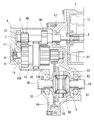
- FIG. 3 Schematic of an electric vehicle employing a vehicle motor drive device according to the present invention
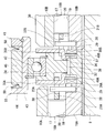
- FIG. 4 is an enlarged sectional view in the vicinity of the shift ring.
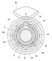
- Sectional view along line VI-VI in FIG. Sectional view along line VII-VII in FIG.
- Sectional view showing shift mechanism 4 is an exploded perspective view of the vicinity of the second-speed cam member in FIG.
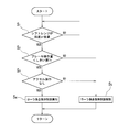
- FIG. 11 is a flowchart showing the control of the motor torque control device shown in FIG. The figure which shows the correspondence of the torque which generate
- FIG. 1 shows an electric vehicle EV in which a pair of left and right front wheels 1 are drive wheels driven by a vehicle motor drive device A according to the present invention, and a pair of left and right rear wheels 2 are driven wheels.
- FIG. 2 shows a hybrid vehicle HV in which a pair of left and right front wheels 1 are main drive wheels driven by an engine E, and a pair of left and right rear wheels 2 are auxiliary drive wheels driven by a vehicle motor drive device A according to the present invention. Indicates.
- the hybrid vehicle HV is provided with a transmission T that shifts the rotation of the engine E and a differential gear D that distributes the rotation output from the transmission T to the left and right front wheels 1.
- a vehicle motor drive device A according to the present invention incorporated in the electric vehicle EV and the hybrid vehicle HV will be described below.
- the vehicle motor drive device A includes an electric motor 3, a transmission 5 that shifts and outputs the rotation of the motor shaft 4 of the electric motor 3, and the rotation output from the transmission 5.
- a differential gear 6 is distributed to the pair of left and right front wheels 1 of the electric vehicle EV shown in FIG. 1 or distributed to the pair of left and right rear wheels 2 of the hybrid vehicle HV shown in FIG.
- the transmission 5 includes an input shaft 7 to which the rotation of the motor shaft 4 is input, an output shaft 8 disposed in parallel to the input shaft 7 at an interval, and an input shaft 7.
- the first-speed input gear 9A and the second-speed input gear 9B provided, and the first-speed output gear 10A and the second-speed output gear 10B provided on the output shaft 8 are provided.
- the motor shaft 4 is coaxially arranged in series with the input shaft 7 and is rotationally driven by the stator 12 of the electric motor 3 fixed to the housing 11.
- the input shaft 7 is rotatably supported by a pair of opposed bearings 13 incorporated in the housing 11, and the shaft end of the input shaft 7 is connected to the motor shaft 4 by spline fitting.
- the output shaft 8 is rotatably supported by a pair of opposed bearings 14 incorporated in the housing 11.
- the first-speed input gear 9A and the second-speed input gear 9B are arranged at an interval in the axial direction, and are fixed to the input shaft 7 so as to rotate integrally with the input shaft 7 around the input shaft 7.
- the first-speed output gear 10A and the second-speed output gear 10B are also arranged at intervals in the axial direction.
- the first-speed output gear 10 ⁇ / b> A is formed in an annular shape that penetrates the output shaft 8, and is supported by the output shaft 8 via a bearing 15, and the output shaft 8 is centered on the output shaft 8. And can be rotated.
- the second speed output gear 10 ⁇ / b> B is also rotatably supported by the output shaft 8 via the bearing 15.
- the first speed input gear 9A and the first speed output gear 10A mesh with each other, and rotation is transmitted between the first speed input gear 9A and the first speed output gear 10A.
- the 2nd speed input gear 9B and the 2nd speed output gear 10B are also meshed, and rotation is transmitted between the 2nd speed input gear 9B and the 2nd speed output gear 10B by the meshing.
- the reduction ratio between the second speed input gear 9B and the second speed output gear 10B is smaller than the reduction ratio between the first speed input gear 9A and the first speed output gear 10A.
- first-speed output gear 10A and the output shaft 8 are incorporated between the first-speed output gear 10A and the output shaft 8 .
- a 2-speed 2-way roller clutch 16B is incorporated between the 2-speed output gear 10B and the output shaft 8 to switch torque transmission and interruption between the 2-speed output gear 10B and the output shaft 8. .
- first-speed two-way roller clutch 16A and the second-speed two-way roller clutch 16B have the same symmetrical configuration, the second-speed two-way roller clutch 16B will be described below, and the first-speed two-way roller clutch 16A will be described.
- the same reference numerals or reference numerals in which the alphabet B at the end is replaced with A will be given, and description thereof will be omitted.
- the two-speed two-way roller clutch 16B includes a cylindrical surface 17 provided on the inner periphery of the second-speed output gear 10B and an annular second gear that is prevented from rotating on the outer periphery of the output shaft 8. It comprises a cam surface 19 formed on the cam member 18B, a roller 20 incorporated between the cam surface 19 and the cylindrical surface 17, a second speed holder 21B for holding the roller 20, and a second speed switch spring 22B.
- the cam surface 19 is a surface that forms a wedge-shaped space that gradually narrows from the circumferential center to both ends in the circumferential direction with the cylindrical surface 17. For example, as shown in FIG. 6, the cam surface 19 faces the cylindrical surface 17. It is a flat surface.
- the 2-speed retainer 21 ⁇ / b> B includes a cylindrical portion 24 in which a plurality of pockets 23 for accommodating the rollers 20 are formed at intervals in the circumferential direction, and a radial direction from one end of the cylindrical portion 24. And an inward flange portion 25 extending inward.
- the radially inner end of the inward flange portion 25 is supported so as to be slidable in the circumferential direction on the outer periphery of the second-speed cam member 18B, and the second-speed cage 21B causes the cam surface 19 and the cylindrical surface 17 to slide.
- rotation relative to the output shaft 8 is possible.
- the inward flange portion 25 of the second-speed cage 21B is restricted from moving in the axial direction, thereby making the second-speed cage 21B immovable in the axial direction.
- each cam surface 19 is formed symmetrically with respect to a virtual plane including the center of rotation, so that the rollers 20 arranged between each cam surface 19 and the cylindrical surface 17 can rotate forward.
- the engagement is possible in both the direction and the reverse direction. That is, when the vehicle is advanced by the torque generated by the electric motor 3, the roller 20 held by the second-speed cage 21B is rotated by rotating the second-speed cage 21B in the normal rotation direction with respect to the output shaft 8. Is engaged with the narrow space on the forward rotation direction side between the cam surface 19 and the cylindrical surface 17, and the torque in the forward rotation direction is transmitted between the second speed output gear 9 ⁇ / b> B and the output shaft 8 via the roller 20.
- the second-speed cage is rotated by rotating the second-speed cage 21B relative to the output shaft 8 in the reverse direction.
- the roller 20 held by 21B is engaged with a narrow space on the reverse rotation direction side between the cam surface 19 and the cylindrical surface 17, and the reverse rotation direction is established between the second speed output gear 9B and the output shaft 8 via the roller 20.
- Can transmit the torque of And it has a function.
- the two-speed switch spring 22 ⁇ / b> B includes a C-shaped annular portion 26 in which a steel wire is wound in a C shape, and a pair extending radially outward from both ends of the C-shaped annular portion 26. Extending portions 27, 27.
- the C-shaped annular portion 26 is fitted into a circular switch spring accommodating recess 28 formed on the axial end surface of the second-speed cam member 18B, and the pair of extending portions 27 and 27 are axial end surfaces of the second-speed cam member 18B. It is inserted in the radial groove 29 formed in.
- the radial groove 29 is formed so as to extend radially outward from the inner peripheral edge of the switch spring accommodating recess 28 and reach the outer periphery of the second speed cam member 18B.
- the extension portion 27 of the second speed switch spring 22B protrudes from the radially outer end of the radial groove 29, and the protruding portion of the extension portion 27 from the radial groove 29 is the cylindrical portion of the second speed cage 21B.
- 24 is inserted into a notch 30 formed at the end in the axial direction.
- the radial groove 29 and the notch 30 are formed to have the same width.
- the extending portions 27, 27 are in contact with the inner surface facing the circumferential direction of the radial groove 29 and the inner surface facing the circumferential direction of the notch 30, respectively, and 2 by the circumferential force acting on the contact surface.
- the speed holder 21B is elastically held in the neutral position.
- the second-speed cage 21B when the second-speed cage 21B is rotated relative to the output shaft 8 and moved in the circumferential direction from the neutral position shown in FIG. 7, the position of the radial groove 29 and the position of the notch 30 are shifted in the circumferential direction. Therefore, the C-shaped annular portion 26 is elastically deformed in a direction in which the distance between the pair of extending portions 27 and 27 is narrowed, and the pair of extending portions 27 and 27 of the two-speed switch spring 22B are caused to radially change by the elastic restoring force The inner surface of the notch 30 and the inner surface of the notch 30 are pressed, and a force in a direction to return the second-speed cage 21B to the neutral position is applied by the pressing.
- the first-speed cam member 18A and the second-speed cam member 18B are prevented from rotating with respect to the output shaft 8 by spline fitting.
- the cam surface 19 of the first speed cam member 18A and the cam surface 19 of the second speed cam member 18B have the same number and the same phase.
- the first speed cam member 18 ⁇ / b> A and the second speed cam member 18 ⁇ / b> B are non-movable in the axial direction by a pair of retaining rings 31 fitted to the outer periphery of the output shaft 8.
- a spacer 32 is incorporated between the first speed cam member 18A and the second speed cam member 18B.
- the first-speed two-way roller clutch 16A and the second-speed two-way roller clutch 16B can be selectively engaged by the transmission actuator 33.
- the shift actuator 33 includes a shift ring 34 that is movably provided in the axial direction between the first-speed output gear 10 ⁇ / b> A and the second-speed output gear 10 ⁇ / b> B, and the first-speed output gear 10 ⁇ / b> A and the shift ring 34.
- the 1st speed friction plate 35A and the 2nd speed friction plate 35B have the same configuration of left-right symmetry, the 2nd speed friction plate 35B will be described below, and the 1st speed friction plate 35A will be referred to as the 2nd speed friction plate 35B.
- Corresponding portions are denoted by the same reference numerals or reference numerals in which the alphabet B at the end is replaced with A, and description thereof is omitted.
- the second-speed friction plate 35B is provided with a projecting piece 36 that engages with the notch 30 of the second-speed retainer 21B.
- the engagement between the projecting piece 36 and the notch 30 causes the second-speed friction plate 35B to hold the second speed.
- the rotation is stopped by the vessel 21B.
- the notch 30 of the second-speed retainer 21B accommodates the projecting piece 36 of the second-speed friction plate 35B so as to be slidable in the axial direction. By this sliding, the second-speed friction plate 35B rotates around the second-speed retainer 21B. It can move in the axial direction with respect to the second-speed retainer 21B between a position in contact with the side surface of the second-speed output gear 10B and a position away from the second-speed output gear 10B.
- a recess 37 is formed at the tip of the projecting piece 36 of the second speed friction plate 35B, and a protrusion 38 that engages with the recess 37 is formed on the outer periphery of the spacer 32.
- the concave portion 37 and the convex portion 38 are engaged with the concave portion 37 and the convex portion 38 in a state where the second speed friction plate 35B is located away from the side surface of the second speed output gear 10B. Is prevented from rotating around the output shaft 8 via the spacer 32. At this time, the second-speed retainer 21B, which is prevented from rotating by the second-speed friction plate 35B, is held in the neutral position.
- a second speed separation spring 39B is incorporated in an axially compressed state, and the second speed friction plate is generated by the elastic restoring force of the second speed separation spring 39B. 35B is urged in a direction away from the side surface of the second-speed output gear 10B.
- the second speed separating spring 39B is a coil spring wound around the outer periphery of the spacer 32, and one end thereof is supported by the end face in the axial direction of the second speed cam member 18B via the second speed washer 39B.
- the 2-speed washer 39B is formed in an annular shape so as to cover the radial groove 29 on the axial end surface of the 2-speed cam member 18B.
- the shift ring 34 presses the first-speed friction plate 35A to contact the side surface of the first-speed output gear 10A, and the shift ring 34 presses the second-speed friction plate 35B to contact the side surface of the second-speed output gear 10B. It is supported so as to be movable in the axial direction between the speed shift position. Further, a shift mechanism 41 that moves the shift ring 34 in the axial direction between the first-speed shift position and the second-speed shift position is provided.
- the shift mechanism 41 is related to a shift sleeve 43 that rotatably supports the shift ring 34 via a rolling bearing 42 and an annular groove 44 provided on the outer periphery of the shift sleeve 43.
- the shift rod 46 is arranged parallel to the output shaft 8 at a distance, and is supported by a pair of sliding bearings 49 incorporated in the housing 11 so as to be slidable in the axial direction.
- the rolling bearing 42 incorporated between the shift ring 34 and the shift sleeve 43 is assembled so as to be immovable in the axial direction with respect to both the shift ring 34 and the shift sleeve 43.
- the rotation of the shift motor 47 is converted into a linear motion by the motion conversion mechanism 48 and transmitted to the shift fork 45, and the linear motion of the shift fork 45 is transmitted to the shift ring 34 via the rolling bearing 42.
- the shift ring 34 is moved in the axial direction.
- a preload spring 50 that is compressible in the axial direction is incorporated in the axial clearance on both sides between the shift fork 45 and the annular groove 44.
- the preload spring 50 is adjusted by adjusting the relative position in the axial direction of the shift fork 45 with respect to the shift sleeve 43.
- a differential drive gear 51 that transmits the rotation of the output shaft 8 to the differential gear 6 is fixed to the output shaft 8.
- the differential gear 6 includes a differential case 53 that is rotatably supported by a pair of bearings 52, a ring gear 54 that is fixed to the differential case 53 coaxially with the rotational center of the differential case 53, meshed with the differential drive gear 51, and the rotational center of the differential case 53.
- the pinion shaft 55 is fixed to the differential case 53 in a direction perpendicular to the pinion shaft 55, the pair of pinions 56 are rotatably supported by the pinion shaft 55, and the pair of left and right side gears 57 meshed with the pair of pinions 56.
- the left side gear 57 is connected to the shaft end portion of the axle 58 connected to the left wheel, and the right side gear 57 is connected to the shaft end portion of the axle 58 connected to the right wheel.
- the output shaft 8 rotates, the rotation of the output shaft 8 is transmitted to the differential case 53 via the differential drive gear 51, and the rotation of the differential case 53 is distributed to the left and right wheels via the pinion 56 and the side gear 57.
- the torque generated by the electric motor 3 is controlled by a motor torque control device 59 shown in FIG.
- This motor torque control device 59 corresponds to the shift range from the shift range detection means 60 (that is, whether the shift lever operated by the driver is in the D range, R range, N range, P range, etc.).
- a signal indicating the current gear position is input from the gear position detecting means 64.
- the motor torque control device 59 outputs a command value for torque generated by the electric motor 3 to the inverter 65.
- the inverter 65 supplies power to the electric motor 3 and controls the supplied power so that torque corresponding to a command value from the motor torque control device 59 is generated in the electric motor 3.
- the first speed holding is performed. 21A is held in the neutral position by the elastic force of the first speed switch spring 22A, and the second speed holder 21B is also held in the neutral position by the elastic force of the second speed switch spring 22B.
- the engagement of the roller 20 is released, and the 2-speed 2-way roller clutch 16B is also released from the engagement of the roller 20.
- the first-speed friction plate 35A comes into contact with the side surface of the first-speed output gear 10A.
- the first-speed friction plate 35A rotates relative to the output shaft 8 by the frictional force between the surfaces, and the first-speed retainer 21A that is prevented from rotating by the first-speed friction plate 35A resists the elastic force of the first-speed switch spring 22A.
- the roller 20 held by the first speed holder 21A is pushed into the narrow portion of the wedge-shaped space between the cylindrical surface 17 and the cam surface 19 and engaged. Become.
- the roller 20 of the first-speed two-way roller clutch 16A or the second-speed two-way roller clutch 16B is engaged between the cam surface 19 and the cylindrical surface 17.
- the accelerator pedal 61 when the accelerator pedal 61 is returned from a state where the accelerator pedal 61 is depressed while the roller 20 held by the first-speed retainer 21A is engaged between the cam surface 19 and the cylindrical surface 17, the accelerator operation amount is reduced. As a result, the torque generated by the electric motor 3 decreases. At this time, if the torque transmitted from the electric motor 3 to the first speed retainer 21A via the first speed output gear 10A and the first speed friction plate 35A becomes smaller than the elastic force of the first speed switch spring 22A, the first speed The first-speed retainer 21A is moved from the engaged position to the neutral position by the elastic force of the switch spring 22A, and the engagement of the roller 20 of the first-speed 2-way roller clutch 16A is released.
- the torque generated by the electric motor 3 increases as the accelerator operation amount increases, so that the electric motor 3 passes through the first speed output gear 10A and the first speed friction plate 35A.
- the torque transmitted to the first-speed retainer 21A is larger than the elastic force of the first-speed switch spring 22A, and the first-speed retainer 21A resists the elastic force of the first-speed switch spring 22A due to the torque.
- the roller 20 of the first-speed two-way roller clutch 16A is re-engaged between the cam surface 19 and the cylindrical surface 17, and unpleasant vibrations / noises are generated by the impact of the re-engagement of the roller 20. There is a fear.
- the motor torque control device 59 shown in FIG. 11 has a torque generated by the electric motor 3 based on signals from the shift range detecting means 60, the accelerator pedal 61, the brake pedal 62, the vehicle speed detecting means 63, and the gear position detecting means 64. By this control, vibration and noise due to re-engagement of the roller 20 are prevented.
- step S 1 based on the signal from the shift range detection means 60, whether the shift range is in the forward range or backward range (D range, R range, etc.) or other shift range (N range, P range, etc.) Is determined (step S 1 ).
- the current brake operation amount is set to be greater than a preset threshold Th based on signals from the brake pedal 62 and the accelerator pedal 61. It is determined whether it is small (step S 2 ) and whether the accelerator pedal 61 is depressed (step S 3 ).
- roller engagement holding torque generated by the electric motor 3 is executed (step S 4 ).
- the roller engagement holding torque is the first speed that attempts to return the first-speed retainer 21A from the engagement position to the neutral position. This torque holds the first-speed retainer 21A in the engaged position against the elastic force of the switch spring 22A.
- the 2-speed 2-way roller clutch 16B is engaged as the current gear, the 2-speed retainer 21B resists the elastic force of the 2-speed switch spring 22B that attempts to return the engagement position to the neutral position. This is the torque that holds the second-speed cage 21B in the engaged position.
- the roller engagement holding torque is a forward rotation torque
- the roller 20 of the two-way roller clutch 16A (or 16B) of the current gear stage is moved between the cam surface 19 and the cylindrical surface 17. Hold in a narrow space between the forward rotation direction.
- the roller engagement holding torque is the torque in the reverse direction
- the roller 20 of the two-way roller clutch 16A (or 16B) of the current gear stage is moved between the cam surface 19 and the cylindrical surface 17. It is held in a narrow space on the reverse direction side.
- step S 2 When the brake operation amount becomes larger than the threshold value Th (step S 2 ), it is considered that the brake pedal 62 has been depressed, so the roller engagement holding control is canceled and the normal torque control is switched (step S). 5 ).
- the normal torque control for example, when the electric motor 3 is used as a brake when the vehicle is moving forward, there is control for causing the electric motor 3 to generate torque in the reverse direction.
- a friction brake device (not shown) installed on the wheels 1 and 2 is operated, control for reducing the generated torque of the electric motor 3 to zero can be mentioned.
- step S 3 when it is determined that the accelerator pedal 61 is depressed (step S 3 ), the roller engagement holding control is canceled and the normal torque control is switched (step S 5 ).
- the normal torque control for example, control for causing the electric motor 3 to generate a torque having a magnitude corresponding to the operation amount of the accelerator pedal 61 can be cited.
- the motor torque control device 59 can also be configured to execute the roller engagement holding control (step S 4 ) regardless of whether the brake pedal 62 is depressed.
- the roller engagement holding control (step S 4 ) is canceled,
- the brake pedal 62 is depressed, the generation of the roller engagement holding torque is stopped, so that the speed can be quickly reduced, and the safety can be improved.
- the roller engagement holding control (step S 4 ) is released when it is determined that the driver's brake operation amount is larger than the threshold value Th, but the brake pedal 62 is depressed.
- the roller engagement holding control (step S 4 ) may be released when it is determined that the brake pedal 62 is depressed based on a binary signal indicating whether or not the brake pedal 62 is depressed. Even in this case, when the brake pedal 62 is depressed, the generation of the roller engagement holding torque is stopped, so that the speed can be quickly reduced, and the safety can be improved.
- the magnitude of the roller engagement holding torque can be constant regardless of the vehicle speed.
- the depression of the accelerator pedal 61 is released in a state where the vehicle speed is low and the roller engagement holding control (step S 4 ) is executed, the vehicle running resistance is small.
- the difference in vehicle driving force that is, roller engagement holding torque
- the vehicle speed can be maintained.
- the depression of the accelerator pedal 61 is released and the roller engagement holding control (step S 4 ) is executed in a state where the vehicle speed is high
- the running resistance of the vehicle reduces the vehicle driving force because the running resistance of the vehicle is large. It will greatly exceed, making it easier for the vehicle to decelerate.
- the driver depresses the accelerator pedal 61 in order to restore the decelerated vehicle speed, and wasteful electricity is consumed.
- the magnitude of the roller engagement holding torque so as to increase as the vehicle speed increases, as shown in FIG.
- the roller engagement holding torque also increases. Therefore, when the depression of the accelerator pedal 61 is released and the roller engagement holding control is executed while the vehicle speed is high, the vehicle travels. The difference between the resistance and the vehicle driving force can be kept small, and the vehicle speed can be easily maintained. As a result, the driver can be prevented from depressing the accelerator pedal 61 unnecessarily, and the amount of electricity consumed can be suppressed.
- the magnitude of the roller engagement holding torque when the vehicle speed is zero, it is preferable to set the magnitude of the roller engagement holding torque to be larger than the running resistance of the vehicle. In this way, when the shift range is the forward range or the reverse range, the vehicle creeps by the torque generated by the electric motor 3 just by releasing the brake pedal 62 from the state where the vehicle is stopped. Driving operation becomes easier.
- the magnitude of the roller engagement holding torque can be set according to the gear position. In this way, the magnitude of the roller engagement holding torque can be adjusted to an optimum magnitude regardless of the gear position when the roller engagement holding control is executed.
Abstract
2ウェイローラクラッチを用いた車両用モータ駆動装置において、アクセルペダルを踏み込んだ状態からアクセルペダルを戻し、その後、再びアクセルペダルを踏み込んだときの振動・異音を防止する。電動モータ(3)の回転が入力される入力軸(7)と、入力軸(7)に設けられた1速入力ギヤ(9A)および2速入力ギヤ(9B)と、1速入力ギヤ(9A)および2速入力ギヤ(9B)にそれぞれ噛合する1速出力ギヤ(10A)および2速出力ギヤ(10B)と、1速の2ウェイローラクラッチ(16A)と、2速の2ウェイローラクラッチ(16B)と、電動モータ(3)のモータトルク制御装置(59)とを設け、モータトルク制御装置(59)は、アクセルペダル(61)が踏み込まれていないときに現変速段の2ウェイローラクラッチ(16A)を係合位置に保持するトルクを電動モータ(3)で発生する制御を実行する。
Description
この発明は、電動モータの回転を変速して車輪へ伝達する車両用モータ駆動装置およびそのモータ駆動装置を搭載した自動車に関する。
電気自動車およびハイブリッド自動車の駆動装置に用いられる車両用モータ駆動装置として、電動モータと、その電動モータの回転を変速する変速機と、その変速機から出力された回転を左右の車輪に分配するディファレンシャルギヤとからなるものが従来から知られている。
この車両用モータ駆動装置を使用すると、走行条件に応じて変速機の変速比を切り換えることにより、駆動および回生時において、効率の高い回転数およびトルク領域で電動モータを使用することが可能となる。また、適切な変速比とすることで、高速走行時の変速機の回転部材の回転速度が下がり、変速機の動力損失が低減して車両のエネルギ効率を向上させることができる。
このような車両用モータ駆動装置として、例えば特許文献1に記載のものが知られている。特許文献1に記載の車両用モータ駆動装置は、変速比の異なる2つの回転伝達経路にそれぞれ設けられた摩擦クラッチと、その摩擦クラッチを選択的に係合させる変速アクチュエータを有する。
ここで、摩擦クラッチは、回転伝達経路の上流側に接続されたプレッシャプレートと、回転伝達経路の下流側に接続されたクラッチプレートとを軸方向に対向して配置したものであり、プレッシャプレートがクラッチプレートから離反した状態では回転の伝達が遮断され、プレッシャプレートをクラッチプレートに接触させると、その接触面間の摩擦力を介して回転が伝達される。
ところで、本願発明の発明者らは、変速比の異なる2つの回転伝達経路を切り換えるクラッチとして、上記の摩擦クラッチではなく、2ウェイローラクラッチを用いた車両用モータ駆動装置を検討し、そのような車両用モータ駆動装置として以下の構成のものを考案した。
電動モータと、その電動モータの回転が入力される入力軸と、入力軸に対して間隔をおいて平行に配置された出力軸と、入力軸に設けられた1速入力ギヤおよび2速入力ギヤと、出力軸に設けられ、1速入力ギヤおよび2速入力ギヤにそれぞれ噛合する1速出力ギヤおよび2速出力ギヤと、出力軸の回転を左右の車輪に分配するディファレンシャルギヤとを有し、
1速出力ギヤと2速出力ギヤは軸受を介して出力軸で回転可能に支持され、
1速出力ギヤと出力軸との間でトルクの伝達と遮断の切換えを行なう1速の2ウェイローラクラッチと、2速出力ギヤと出力軸との間でトルクの伝達と遮断の切換えを行なう2速の2ウェイローラクラッチと、1速の2ウェイローラクラッチと2速の2ウェイローラクラッチとを選択的に係合させる変速アクチュエータを設けた車両用モータ駆動装置。
1速出力ギヤと2速出力ギヤは軸受を介して出力軸で回転可能に支持され、
1速出力ギヤと出力軸との間でトルクの伝達と遮断の切換えを行なう1速の2ウェイローラクラッチと、2速出力ギヤと出力軸との間でトルクの伝達と遮断の切換えを行なう2速の2ウェイローラクラッチと、1速の2ウェイローラクラッチと2速の2ウェイローラクラッチとを選択的に係合させる変速アクチュエータを設けた車両用モータ駆動装置。
ここで、1速の2ウェイローラクラッチは、1速出力ギヤの内周と出力軸の外周のうち一方に設けられた円筒面と、他方に設けられたカム面と、そのカム面と円筒面の間に組み込まれたローラと、そのローラを保持し、カム面と円筒面の間にローラを係合させる係合位置とローラの係合を解除する中立位置との間で出力軸に対して相対回転可能に設けられた1速保持器と、その1速保持器を中立位置に弾性保持する1速スイッチばねとからなる構成のものであり、1速保持器を係合位置と中立位置の間で周方向に移動させることにより、トルクの伝達と遮断を切り換えることができるようになっている。2速の2ウェイローラクラッチも、1速の2ウェイローラクラッチと同様の構成である。
また、変速アクチュエータは、1速保持器に対して回り止めされかつ1速出力ギヤの側面に接触する位置と離反する位置との間で軸方向に移動可能に設けられた1速摩擦板と、その1速摩擦板を1速出力ギヤの側面から離反する方向に付勢する1速離反ばねと、2速保持器に対して回り止めされかつ2速出力ギヤの側面に接触する位置と離反する位置との間で軸方向に移動可能に設けられた2速摩擦板と、その2速摩擦板を2速出力ギヤの側面から離反する方向に付勢する2速離反ばねと、1速摩擦板を押圧して1速出力ギヤの側面に接触させる1速シフト位置と2速摩擦板を押圧して2速出力ギヤの側面に接触させる2速シフト位置との間で軸方向に移動可能に設けられたシフトリングと、そのシフトリングを軸方向に移動させるシフト機構とからなる。
上記構成からなる車両用モータ駆動装置は、シフト機構の作動により、シフトリングを1速シフト位置に移動させたときは、1速摩擦板が1速出力ギヤの側面に接触し、その接触面間の摩擦力によって1速摩擦板が出力軸に対して相対回転し、この1速摩擦板に回り止めされた1速保持器が1速スイッチばねの弾性力に抗して中立位置から係合位置に移動するため、1速保持器に保持されたローラがカム面と円筒面の間に係合し、1速出力ギヤと出力軸との間でトルクの伝達が行われる。同様に、シフトリングを2速シフト位置に移動させたときは、2速保持器に保持されたローラがカム面と円筒面の間に係合し、2速出力ギヤと出力軸との間でトルクの伝達が行われる。
ところで、この発明の発明者は、上記構成の車両用モータ駆動装置を採用した場合、1速の2ウェイローラクラッチまたは2速の2ウェイローラクラッチのローラがカム面と円筒面の間に係合した状態において、アクセルペダルを踏み込んだ状態からアクセルペダルを戻し、その後、再びアクセルペダルを踏み込んだときに、不快な振動・異音が発生するおそれがある問題を見出した。この問題を以下に説明する。
例えば、1速の2ウェイローラクラッチが係合した状態において、アクセルペダルを踏み込んだ状態からアクセルペダルを戻すと、アクセル操作量の減少に伴って電動モータの発生するトルクが小さくなるため、電動モータから1速出力ギヤと1速摩擦板とを介して1速保持器に伝達するトルクが1速スイッチばねの弾性力よりも小さくなり、その結果、1速スイッチばねの弾性力により1速保持器が係合位置から中立位置に移動し、1速の2ウェイローラクラッチの係合が解除される。
その後、再びアクセルペダルを踏み込むと、アクセル操作量の増大に伴って電動モータの発生するトルクが大きくなるため、電動モータから1速出力ギヤと1速摩擦板とを介して1速保持器に伝達するトルクが1速スイッチばねの弾性力よりも大きくなり、そのトルクにより1速保持器が1速スイッチばねの弾性力に抗して中立位置から係合位置に移動し、1速の2ウェイローラクラッチのローラがカム面と円筒面の間に再び係合し、このローラが再係合する衝撃により不快な振動・異音が発生するおそれがある。
同様に、2速の2ウェイローラクラッチが係合した状態においても、アクセルペダルを踏み込んだ状態からアクセルペダルを戻すと、2速スイッチばねの弾性力により2速保持器が係合位置から中立位置に移動し、2速の2ウェイローラクラッチの係合が解除され、その後、再びアクセルペダルを踏み込んだときに、2速の2ウェイローラクラッチのローラが再係合するため、この再係合の衝撃により不快な振動・異音が発生するおそれがある。
この発明が解決しようとする課題は、2ウェイローラクラッチを用いた車両用モータ駆動装置において、アクセルペダルを踏み込んだ状態からアクセルペダルを戻し、その後、再びアクセルペダルを踏み込んだときの振動・異音を防止することである。
上記の課題を解決するため、この発明においては、電動モータと、その電動モータの回転が入力される入力軸と、前記入力軸に対して間隔をおいて平行に配置された出力軸と、前記入力軸に設けられた第1入力ギヤおよび第2入力ギヤと、前記出力軸に設けられ、前記第1入力ギヤおよび第2入力ギヤにそれぞれ噛合する第1出力ギヤおよび第2出力ギヤと、前記出力軸の回転を左右の車輪に分配するディファレンシャルギヤと、前記電動モータの発生トルクを制御するモータトルク制御装置とを有し、
前記第1入力ギヤと第2入力ギヤと入力軸の組と、前記第1出力ギヤと第2出力ギヤと出力軸の組とのうち一方を、第1クラッチギヤと第2クラッチギヤとこれらのクラッチギヤを軸受を介して回転可能に支持するクラッチギヤ支持軸とし、
前記第1クラッチギヤとクラッチギヤ支持軸との間でトルクの伝達と遮断の切換えを行なう第1の2ウェイローラクラッチと、前記第2クラッチギヤとクラッチギヤ支持軸との間でトルクの伝達と遮断の切換えを行なう第2の2ウェイローラクラッチと、前記第1の2ウェイローラクラッチと第2の2ウェイローラクラッチとを選択的に係合させる変速アクチュエータを設け、
前記第1の2ウェイローラクラッチは、第1クラッチギヤの内周とクラッチギヤ支持軸の外周のうち一方に設けられた円筒面と、他方に設けられたカム面と、そのカム面と前記円筒面の間に組み込まれたローラと、そのローラを保持し、前記カム面と円筒面の間にローラを係合させる係合位置とローラの係合を解除する中立位置との間で前記クラッチギヤ支持軸に対して相対回転可能に設けられた第1保持器と、その第1保持器を前記中立位置に弾性保持する第1スイッチばねとからなり、
前記第2の2ウェイローラクラッチは、第2クラッチギヤの内周とクラッチギヤ支持軸の外周のうち一方に設けられた円筒面と、他方に設けられたカム面と、そのカム面と前記円筒面の間に組み込まれたローラと、そのローラを保持し、前記カム面と円筒面の間にローラを係合させる係合位置とローラの係合を解除する中立位置との間で前記クラッチギヤ支持軸に対して相対回転可能に設けられた第2保持器と、その第2保持器を前記中立位置に弾性保持する第2スイッチばねとからなり、
前記変速アクチュエータは、前記第1保持器に対して回り止めされかつ前記第1クラッチギヤの側面に接触する位置と離反する位置との間で軸方向に移動可能に設けられた第1摩擦板と、その第1摩擦板を前記第1クラッチギヤの側面から離反する方向に付勢する第1離反ばねと、前記第2保持器に対して回り止めされかつ前記第2クラッチギヤの側面に接触する位置と離反する位置との間で軸方向に移動可能に設けられた第2摩擦板と、その第2摩擦板を前記第2クラッチギヤの側面から離反する方向に付勢する第2離反ばねと、前記第1摩擦板を押圧して前記第1クラッチギヤの側面に接触させる第1シフト位置と前記第2摩擦板を押圧して前記第2クラッチギヤの側面に接触させる第2シフト位置との間で軸方向に移動可能に設けられたシフトリングと、そのシフトリングを軸方向に移動させるシフト機構とからなり、
前記モータトルク制御装置は、アクセルペダルが踏み込まれているか否かを判定するアクセル操作判定手段と、そのアクセル操作判定手段でアクセルペダルが踏み込まれていないと判定されたときに、現変速段の2ウェイローラクラッチの保持器を係合位置から中立位置に戻そうとする前記スイッチばねの弾性力に抗して現変速段の2ウェイローラクラッチの保持器を係合位置に保持するトルクを前記電動モータで発生するローラ係合保持制御を実行するローラ係合保持制御手段とを有する構成を車両用モータ駆動装置に採用した。
この構成を採用した車両用モータ駆動装置は、シフトリングが第1シフト位置にあるときは、第1摩擦板が第1クラッチギヤの側面に接触し、その接触面間の摩擦力によって第1摩擦板がクラッチギヤ支持軸に対して相対回転し、この第1摩擦板に回り止めされた第1保持器が第1スイッチばねの弾性力に抗して中立位置から係合位置に移動するため、第1保持器に保持されたローラがカム面と円筒面の間に係合し、第1クラッチギヤとクラッチギヤ支持軸との間でトルクの伝達が行われる。
そして、上記構成の車両用モータ駆動装置を採用した場合、第1の2ウェイローラクラッチが係合した状態において、アクセルペダルを踏み込んだ状態からアクセルペダルを戻すと、アクセル操作量の減少に伴って電動モータの発生するトルクが小さくなるが、前記アクセル操作判定手段でアクセルペダルが踏み込まれていないと判定されたときに、前記ローラ係合保持制御手段が、第1保持器を係合位置から中立位置に戻そうとする第1スイッチばねの弾性力に抗して第1保持器を係合位置に保持するトルクを前記電動モータで発生するローラ係合保持制御を実行するため、第1保持器が係合位置から中立位置に移動せず、第1の2ウェイローラクラッチの係合が保持される。第2の2ウェイローラクラッチが係合した状態においても同様である。このように、アクセルペダルを戻してから再びアクセルペダルを踏み込むまでの一連の動作の間、現変速段の2ウェイローラクラッチの係合が解除されないため、ローラの再係合による振動・異音が発生しない。
前記モータトルク制御装置は、ブレーキペダルが踏み込まれているか否かを問わず、前記ローラ係合保持制御を実行するように構成することも可能であるが、前記モータトルク制御装置は、運転者のブレーキ操作量が予め設定されたしきい値よりも大きいか否かを判定するブレーキ操作判定手段を更に設け、前記ローラ係合保持制御手段は、そのブレーキ操作判定手段で運転者のブレーキ操作量が前記しきい値よりも大きいと判定されたときに前記ローラ係合保持制御を解除するように構成すると好ましい。このようにすると、ブレーキペダルが踏み込まれたときに、ローラ係合保持制御によるトルクの発生を中止するため速やかに減速することが可能となり、安全性を高めることができる。
また、前記モータトルク制御装置に、ブレーキペダルが踏み込まれているか否か判定するブレーキ操作判定手段を更に設け、前記ローラ係合保持制御手段は、そのブレーキ操作判定手段でブレーキペダルが踏み込まれていると判定されたときに前記ローラ係合保持制御を解除するように構成してもよい。このようにしても、ブレーキペダルが踏み込まれたときに、ローラ係合保持制御によるトルクの発生を中止するため速やかに減速することが可能となり、安全性を高めることができる。
前記ローラ係合保持制御手段は、前記ローラ係合保持制御により前記電動モータで発生するトルクの大きさを車速によらず一定とすることも可能である。このようにした場合、車速が遅い状態においてアクセルペダルの踏み込みを解除し、前記ローラ係合保持制御が実行されたときは、車両の走行抵抗が小さいため、車両の走行抵抗と車両駆動力(すなわち前記ローラ係合保持制御により電動モータが発生するトルク)の差が小さく、車両の速度を維持することができる。しかしながら、車速が速い状態においてアクセルペダルの踏み込みを解除し、前記ローラ係合保持制御が実行されたときは、車両の走行抵抗が大きいため、車両の走行抵抗が車両駆動力を大きく上回ってしまい、車両が減速しやすくなる。その結果、減速した車速を元に戻そうと運転者がアクセルペダルを踏み込むため、無駄な電気が消費される。
そこで、前記ローラ係合保持制御により前記電動モータで発生するトルクの大きさは、車速が速いほど大きくなるように設定すると好ましい。このようにすると、車速が速いときは、前記ローラ係合保持制御により電動モータが発生するトルクも大きくなるため、車速が速い状態においてアクセルペダルの踏み込みを解除して前記ローラ係合保持制御が実行されたときに、車両の走行抵抗と車両駆動力の差を小さく抑えることができ、車両の速度を維持しやすくなる。その結果、運転者が無駄にアクセルペダルを踏み込むのを抑制することができ、電気消費量を抑えることが可能となる。
また、前記ローラ係合保持制御により前記電動モータで発生するトルクの大きさは、変速段に応じて設定することができる。このようにすると、前記ローラ係合保持制御が実行されるときの変速段にかかわらず、前記ローラ係合保持制御により電動モータで発生するトルクの大きさを最適な大きさに調整することができる。
また、この発明では、上記の車両用モータ駆動装置を用いた電気自動車として、左右一対の前輪と左右一対の後輪のうち少なくとも一方を上記の車両用モータ駆動装置で駆動するようにした電気自動車を提供する。
また、この発明では、上記の車両用モータ駆動装置を用いたハイブリッド自動車として、左右一対の前輪と左右一対の後輪のうち一方をエンジンで駆動し、他方を上記の車両用モータ駆動装置で駆動するようにしたハイブリッド自動車を提供する。
この発明の車両用モータ駆動装置を採用すると、アクセルペダルを踏み込んだ状態からアクセルペダルを戻したときに、電動モータが、現変速段の保持器を係合位置から中立位置に戻そうとするスイッチばねの弾性力に抗して現変速段の保持器を係合位置に保持するトルクを発生するため、現変速段の保持器が係合位置から中立位置に移動せず、現変速段の2ウェイローラクラッチの係合が保持される。したがって、アクセルペダルを戻してから再びアクセルペダルを踏み込んだときに、ローラの再係合による振動・異音が発生しない。
図1は、左右一対の前輪1をこの発明に係る車両用モータ駆動装置Aで駆動される駆動輪とし、左右一対の後輪2を従動輪とした電気自動車EVを示す。
図2は、左右一対の前輪1をエンジンEによって駆動される主駆動輪とし、左右一対の後輪2をこの発明に係る車両用モータ駆動装置Aで駆動される補助駆動輪としたハイブリッド自動車HVを示す。ハイブリッド自動車HVには、エンジンEの回転を変速するトランスミッションTと、トランスミッションTから出力された回転を左右の前輪1に分配するディファレンシャルギヤDとが設けられている。
この電気自動車EVおよびハイブリッド自動車HVに組み込まれたこの発明に係る車両用モータ駆動装置Aについて以下に説明する。
図3に示すように、車両用モータ駆動装置Aは、電動モータ3と、電動モータ3のモータ軸4の回転を変速して出力する変速機5と、その変速機5から出力された回転を図1に示す電気自動車EVの左右一対の前輪1に分配し、または、図2に示すハイブリッド自動車HVの左右一対の後輪2に分配するディファレンシャルギヤ6とを有する。
変速機5は、図3に示すように、モータ軸4の回転が入力される入力軸7と、入力軸7に対して間隔をおいて平行に配置された出力軸8と、入力軸7に設けられた1速入力ギヤ9Aおよび2速入力ギヤ9Bと、出力軸8に設けられた1速出力ギヤ10Aおよび2速出力ギヤ10Bとを有する。
モータ軸4は、入力軸7と同軸上に直列に配置されており、ハウジング11に固定された電動モータ3のステータ12で回転駆動される。入力軸7は、ハウジング11内に組込まれた対向一対の軸受13により回転可能に支持され、入力軸7の軸端はスプライン嵌合によってモータ軸4に接続されている。出力軸8は、ハウジング11内に組込まれた対向一対の軸受14により回転可能に支持されている。
1速入力ギヤ9Aと2速入力ギヤ9Bは軸方向に間隔をおいて配置され、入力軸7を中心として入力軸7と一体に回転するように入力軸7に固定されている。1速出力ギヤ10Aと2速出力ギヤ10Bも軸方向に間隔をおいて配置されている。
図4に示すように、1速出力ギヤ10Aは、出力軸8を貫通させる環状に形成され、軸受15を介して出力軸8で支持されており、出力軸8を中心として出力軸8に対して回転可能となっている。同様に、2速出力ギヤ10Bも、軸受15を介して出力軸8で回転可能に支持されている。
1速入力ギヤ9Aと1速出力ギヤ10Aは互いに噛合しており、その噛合によって1速入力ギヤ9Aと1速出力ギヤ10Aの間で回転が伝達するようになっている。2速入力ギヤ9Bと2速出力ギヤ10Bも噛合しており、その噛合によって2速入力ギヤ9Bと2速出力ギヤ10Bの間で回転が伝達するようになっている。2速入力ギヤ9Bと2速出力ギヤ10Bの減速比は、1速入力ギヤ9Aと1速出力ギヤ10Aの減速比よりも小さい。
1速出力ギヤ10Aと出力軸8の間には、1速出力ギヤ10Aと出力軸8の間でトルクの伝達と遮断の切換えを行なう1速の2ウェイローラクラッチ16Aが組込まれている。また、2速出力ギヤ10Bと出力軸8の間には、2速出力ギヤ10Bと出力軸8の間でトルクの伝達と遮断の切換えを行なう2速の2ウェイローラクラッチ16Bが組込まれている。
1速の2ウェイローラクラッチ16Aと2速の2ウェイローラクラッチ16Bは、左右対称の同一構成であるため、2速の2ウェイローラクラッチ16Bを以下に説明し、1速の2ウェイローラクラッチ16Aについては、2速の2ウェイローラクラッチ16Bに対応する部分に同一の符号または末尾のアルファベットBをAに置き換えた符号を付して説明を省略する。
図5~図7に示すように、2速の2ウェイローラクラッチ16Bは、2速出力ギヤ10Bの内周に設けられた円筒面17と、出力軸8の外周に回り止めした環状の2速カム部材18Bに形成されたカム面19と、カム面19と円筒面17の間に組み込まれたローラ20と、ローラ20を保持する2速保持器21Bと、2速スイッチばね22Bとからなる。カム面19は、円筒面17との間で周方向中央から周方向両端に向かって次第に狭くなるくさび形空間を形成するような面であり、例えば、図6に示すように円筒面17と対向する平坦面である。
図4、図10に示すように、2速保持器21Bは、ローラ20を収容する複数のポケット23が周方向に間隔をおいて形成された円筒部24と、円筒部24の一端から径方向内方に延び出す内向きフランジ部25とを有する。内向きフランジ部25の径方向内端は、2速カム部材18Bの外周で周方向にスライド可能に支持され、この周方向のスライドによって、2速保持器21Bは、カム面19と円筒面17の間にローラ20を係合させる係合位置とローラ20の係合を解除する中立位置との間で出力軸8に対して相対回転可能となっている。また、2速保持器21Bの内向きフランジ部25は軸方向両側への移動が規制され、これにより2速保持器21Bが軸方向に非可動とされている。
図6に示すように、各カム面19は、回転中心を含む仮想平面に対して対称に形成され、これにより、各カム面19と円筒面17の間に配置されたローラ20は、正転方向と逆転方向の両方向で係合可能となっている。すなわち、電動モータ3が発生するトルクにより車両を前進させるときは、2速保持器21Bを出力軸8に対して正転方向に相対回転させることにより、2速保持器21Bに保持されたローラ20を、カム面19と円筒面17の間の正転方向側の狭小空間に係合させ、そのローラ20を介して2速出力ギヤ9Bと出力軸8の間で正転方向のトルクを伝達することが可能となっており、一方、電動モータ3が発生するトルクにより車両を後退させるときは、2速保持器21Bを出力軸8に対して逆転方向に相対回転させることにより、2速保持器21Bに保持されたローラ20を、カム面19と円筒面17の間の逆転方向側の狭小空間に係合させ、そのローラ20を介して2速出力ギヤ9Bと出力軸8の間で逆転方向のトルクを伝達することが可能となっている。
図7、図10に示すように、2速スイッチばね22Bは、鋼線をC形に巻いたC形環状部26と、C形環状部26の両端からそれぞれ径方向外方に延出する一対の延出部27,27とからなる。C形環状部26は、2速カム部材18Bの軸方向端面に形成された円形のスイッチばね収容凹部28に嵌め込まれ、一対の延出部27,27は、2速カム部材18Bの軸方向端面に形成された径方向溝29に挿入されている。
径方向溝29は、スイッチばね収容凹部28の内周縁から径方向外方に延びて2速カム部材18Bの外周に至るように形成されている。2速スイッチばね22Bの延出部27は、径方向溝29の径方向外端から突出しており、その延出部27の径方向溝29からの突出部分が、2速保持器21Bの円筒部24の軸方向端部に形成された切欠き30に挿入されている。径方向溝29と切欠き30は同じ幅に形成されている。
延出部27,27は、径方向溝29の周方向で対向する内面と、切欠き30の周方向で対向する内面にそれぞれ接触しており、その接触面に作用する周方向の力によって2速保持器21Bを中立位置に弾性保持している。
すなわち、2速保持器21Bを出力軸8に対して相対回転させて、図7に示す中立位置から周方向に移動させると、径方向溝29の位置と切欠き30の位置が周方向にずれるため、一対の延出部27,27の間隔が狭まる方向にC形環状部26が弾性変形し、その弾性復元力によって2速スイッチばね22Bの一対の延出部27,27が径方向溝29の内面と切欠き30の内面を押圧し、その押圧によって2速保持器21Bを中立位置に戻す方向の力が作用するようになっている。
図4に示すように、1速カム部材18Aと2速カム部材18Bの出力軸8に対する回り止めは、スプライン嵌合によって行なわれている。1速カム部材18Aのカム面19と2速カム部材18Bのカム面19は同数かつ同位相となっている。また、1速カム部材18Aと2速カム部材18Bは、出力軸8の外周に嵌合した一対の止め輪31によって軸方向に非可動となっている。1速カム部材18Aと2速カム部材18Bの間には間座32が組み込まれている。
1速の2ウェイローラクラッチ16Aと2速の2ウェイローラクラッチ16Bは、変速アクチュエータ33により選択的に係合することができるようになっている。
図5に示すように、変速アクチュエータ33は、1速出力ギヤ10Aと2速出力ギヤ10Bの間に軸方向に移動可能に設けられたシフトリング34と、1速出力ギヤ10Aとシフトリング34の間に組み込まれた1速摩擦板35Aと、2速出力ギヤ10Bとシフトリング34の間に組み込まれた2速摩擦板35Bとを有する。
ここで、1速摩擦板35Aと2速摩擦板35Bは、左右対称の同一構成であるため、2速摩擦板35Bを以下に説明し、1速摩擦板35Aについては、2速摩擦板35Bに対応する部分に同一の符号または末尾のアルファベットBをAに置き換えた符号を付して説明を省略する。
2速摩擦板35Bには、2速保持器21Bの切欠き30に係合する突片36が設けられ、この突片36と切欠き30の係合によって、2速摩擦板35Bが2速保持器21Bに回り止めされている。2速保持器21Bの切欠き30は、2速摩擦板35Bの突片36を軸方向にスライド可能に収容しており、このスライドによって、2速摩擦板35Bは、2速保持器21Bに回り止めされた状態のまま、2速出力ギヤ10Bの側面に接触する位置と離反する位置との間で、2速保持器21Bに対して軸方向に移動可能となっている。
2速摩擦板35Bの突片36の先端に凹部37が形成されて、間座32の外周には、凹部37に係合する凸部38が形成されている。そして、凹部37と凸部38は、2速摩擦板35Bが2速出力ギヤ10Bの側面から離反した位置にある状態では、凹部37と凸部38が係合することで、2速摩擦板35Bを間座32を介して出力軸8に回り止めし、このとき、2速摩擦板35Bに回り止めされた2速保持器21Bが中立位置に保持されるようになっている。また、2速摩擦板35Bが2速出力ギヤ10Bの側面に接触する位置にある状態では、凹部37と凸部38の係合が解除することで、2速摩擦板35Bの回り止めが解除されるようになっている。
2速摩擦板35Bと2速カム部材18Bの間には、軸方向に圧縮された状態で2速離反ばね39Bが組み込まれており、この2速離反ばね39Bの弾性復元力によって2速摩擦板35Bが2速出力ギヤ10Bの側面から離反する方向に付勢されている。
2速離反ばね39Bは、間座32の外周に沿って巻回されたコイルスプリングであり、その一端が2速ワッシャ39Bを介して2速カム部材18Bの軸方向端面で支持されている。2速ワッシャ39Bは、2速カム部材18Bの軸方向端面の径方向溝29を覆うように環状に形成されている。
シフトリング34は、1速摩擦板35Aを押圧して1速出力ギヤ10Aの側面に接触させる1速シフト位置と、2速摩擦板35Bを押圧して2速出力ギヤ10Bの側面に接触させる2速シフト位置との間で軸方向に移動可能に支持されている。また、シフトリング34を1速シフト位置と2速シフト位置の間で軸方向に移動させるシフト機構41が設けられている。
図8、図9に示すように、シフト機構41は、シフトリング34を転がり軸受42を介して回転可能に支持するシフトスリーブ43と、そのシフトスリーブ43の外周に設けられた環状溝44に係合する二股状のシフトフォーク45と、シフトフォーク45が固定されたシフトロッド46と、シフトモータ47と、シフトモータ47の回転をシフトロッド46の直線運動に変換する運動変換機構48(送りねじ機構等)とからなる。
図9に示すように、シフトロッド46は、出力軸8に対して間隔をおいて平行に配置され、ハウジング11内に組み込まれた一対の滑り軸受49で軸方向にスライド可能に支持されている。シフトリング34とシフトスリーブ43の間に組み込まれた転がり軸受42は、シフトリング34とシフトスリーブ43のいずれに対しても軸方向に非可動となるように組み付けられている。
このシフト機構41は、シフトモータ47の回転が運動変換機構48により直線運動に変換されてシフトフォーク45に伝達し、そのシフトフォーク45の直線運動が転がり軸受42を介してシフトリング34に伝達することにより、シフトリング34を軸方向に移動させる。
図5に示すように、シフトフォーク45と環状溝44の間の両側の軸方向隙間には、軸方向に圧縮可能な予圧ばね50が組み込まれている。これにより、シフトリング34で1速摩擦板35Aを押圧して1速出力ギヤ10Aの側面に接触させるときに、シフトスリーブ43に対するシフトフォーク45の軸方向の相対位置を調節することによって予圧ばね50のばね力を調節し、1速摩擦板35Aと1速出力ギヤ10Aの接触面間の摩擦力を調整することが可能となっている。また、シフトリング34で2速摩擦板35Bを押圧して2速出力ギヤ10Bの側面に接触させるときも、2速摩擦板35Bと2速出力ギヤ10Bの接触面間の摩擦力を調整することが可能となっている。
図3に示すように、出力軸8には、出力軸8の回転をディファレンシャルギヤ6に伝達するディファレンシャル駆動ギヤ51が固定されている。
ディファレンシャルギヤ6は、一対の軸受52で回転可能に支持されたデフケース53と、デフケース53の回転中心と同軸にデフケース53に固定され、ディファレンシャル駆動ギヤ51に噛合するリングギヤ54と、デフケース53の回転中心と直角な方向にデフケース53に固定されたピニオン軸55と、ピニオン軸55に回転可能に支持された一対のピニオン56と、その一対のピニオン56に噛合する左右一対のサイドギヤ57とからなる。左側のサイドギヤ57には、左側の車輪に接続されたアクスル58の軸端部が接続され、右側のサイドギヤ57には、右側の車輪に接続されたアクスル58の軸端部が接続されている。出力軸8が回転するとき、出力軸8の回転はディファレンシャル駆動ギヤ51を介してデフケース53に伝達され、そのデフケース53の回転がピニオン56とサイドギヤ57を介して左右の車輪に分配される。
電動モータ3の発生するトルクは、図11に示すモータトルク制御装置59で制御される。このモータトルク制御装置59には、シフトレンジ検出手段60からシフトレンジ(すなわち、運転者により操作されるシフトレバーが、Dレンジ、Rレンジ、Nレンジ、Pレンジ等のいずれにあるか)に対応する信号が、アクセルペダル61からアクセルペダル61の操作量に対応する信号が、ブレーキペダル62からブレーキペダル62の操作量に対応する信号が、車速検出手段63からは車両の走行速度に対応する信号が、変速段検出手段64からは、現在の変速段(1速と2速のいずれか)を示す信号が入力される。また、モータトルク制御装置59は、電動モータ3の発生するトルクの指令値をインバータ65に出力する。インバータ65は、電動モータ3に電力を供給するとともに、その供給電力を、モータトルク制御装置59からの指令値に対応するトルクが電動モータ3で発生するよう制御する。
以下に、車両用モータ駆動装置Aの動作例を説明する。
まず、図5に示すように、1速摩擦板35Aが1速出力ギヤ10Aの側面から離反し、かつ、2速摩擦板35Bも2速出力ギヤ10Bの側面から離反した状態では、1速保持器21Aは1速スイッチばね22Aの弾性力により中立位置に保持され、2速保持器21Bも2速スイッチばね22Bの弾性力により中立位置に保持されるため、1速の2ウェイローラクラッチ16Aはローラ20の係合が解除された状態となり、2速の2ウェイローラクラッチ16Bもローラ20の係合が解除された状態となる。
この状態では、図3に示す電動モータ3の駆動により入力軸7が回転しても、1速の2ウェイローラクラッチ16Aと2速の2ウェイローラクラッチ16Bによって回転の伝達が遮断されるため、1速出力ギヤ10Aおよび2速出力ギヤ10Bは空転し、入力軸7の回転は出力軸8に伝達されない。
次に、シフト機構41を作動させて、図5に示すシフトリング34を1速出力ギヤ10Aに向けて移動させると、1速摩擦板35Aが1速出力ギヤ10Aの側面に接触し、その接触面間の摩擦力によって1速摩擦板35Aが出力軸8に対して相対回転し、この1速摩擦板35Aに回り止めされた1速保持器21Aが1速スイッチばね22Aの弾性力に抗して中立位置から係合位置に移動するため、1速保持器21Aに保持されたローラ20が、円筒面17とカム面19の間のくさび形空間の狭小部分に押し込まれて係合した状態となる。
この状態では、1速出力ギヤ10Aの回転は、1速の2ウェイローラクラッチ16Aを介して出力軸8に伝達され、出力軸8の回転が、ディファレンシャルギヤ6を介してアクスル58に伝達される。その結果、図1に示す電気自動車EVにおいては、駆動輪としての前輪1が回転駆動され、図2に示すハイブリッド自動車HVにおいては補助駆動輪としての後輪2が回転駆動される。
次に、シフト機構41の作動により、シフトリング34を1速シフト位置から2速シフト位置に向かって軸方向移動させると、1速摩擦板35Aと1速出力ギヤ10Aの接触面間の摩擦力が小さくなるため、1速スイッチばね22Aの弾性力により1速保持器21Aが係合位置から中立位置に移動し、この1速保持器21Aの移動によって1速の2ウェイローラクラッチ16Aの係合が解除される。
シフトリング34が2速シフト位置に到達すると、2速摩擦板35Bがシフトリング34で押圧されて2速出力ギヤ10Bの側面に接触し、その接触面間の摩擦力によって2速摩擦板35Bが出力軸8に対して相対回転し、2速摩擦板35Bに回り止めされた2速保持器21Bが2速スイッチばね22Bの弾性力に抗して中立位置から係合位置に移動するため、2速保持器21Bに保持されたローラ20が、円筒面17とカム面19の間のくさび形空間の狭小部分に押し込まれて係合した状態となる。
この状態では、2速出力ギヤ10Bの回転は、2速の2ウェイローラクラッチ16Bを介して出力軸8に伝達され、出力軸8の回転がディファレンシャルギヤ6を介してアクスル58に伝達される。
同様に、シフトリング34を2速シフト位置から1速シフト位置に軸方向移動させることにより、2速の2ウェイローラクラッチ16Bの係合を解除して、1速の2ウェイローラクラッチ16Aを係合させることができる。
ところで、上記構成の車両用モータ駆動装置Aにおいては、1速の2ウェイローラクラッチ16Aまたは2速の2ウェイローラクラッチ16Bのローラ20がカム面19と円筒面17の間に係合した状態において、アクセルペダル61を踏み込んだ状態からアクセルペダル61を戻し、その後、再びアクセルペダル61を踏み込んだときに、不快な振動・異音が発生する可能性がある。
例えば、1速保持器21Aに保持されたローラ20がカム面19と円筒面17の間に係合した状態において、アクセルペダル61を踏み込んだ状態からアクセルペダル61を戻すと、アクセル操作量の減少に伴って電動モータ3の発生するトルクが小さくなる。このとき、電動モータ3から1速出力ギヤ10Aと1速摩擦板35Aとを介して1速保持器21Aに伝達するトルクが1速スイッチばね22Aの弾性力よりも小さくなってしまうと、1速スイッチばね22Aの弾性力により1速保持器21Aが係合位置から中立位置に移動し、1速の2ウェイローラクラッチ16Aのローラ20の係合が解除される。
この場合、再びアクセルペダル61を踏み込むと、アクセル操作量の増大に伴って電動モータ3の発生するトルクが大きくなるため、電動モータ3から1速出力ギヤ10Aと1速摩擦板35Aとを介して1速保持器21Aに伝達するトルクが1速スイッチばね22Aの弾性力よりも大きくなり、そのトルクにより1速保持器21Aが1速スイッチばね22Aの弾性力に抗して中立位置から係合位置に移動し、1速の2ウェイローラクラッチ16Aのローラ20がカム面19と円筒面17の間に再び係合し、このローラ20が再係合する衝撃により不快な振動・異音が発生するおそれがある。
同様に、2速保持器21Bに保持されたローラ20がカム面19と円筒面17の間に係合した状態においても、アクセルペダル61を踏み込んだ状態からアクセルペダル61を戻したときに、電動モータ3から2速出力ギヤ10Bと2速摩擦板35Bとを介して2速保持器21Bに伝達するトルクが2速スイッチばね22Bの弾性力よりも小さくなってしまうと、2速スイッチばね22Bの弾性力により2速保持器21Bが係合位置から中立位置に移動し、2速の2ウェイローラクラッチ16Bのローラ20の係合が解除され、その後、再びアクセルペダル61を踏み込んだときに、2速の2ウェイローラクラッチ16Bのローラ20が再係合するため、この再係合の衝撃により不快な振動・異音が発生するおそれがある。
そこで、図11に示すモータトルク制御装置59は、シフトレンジ検出手段60、アクセルペダル61、ブレーキペダル62、車速検出手段63、変速段検出手段64からの信号に基づいて電動モータ3の発生するトルクを制御し、この制御によって、ローラ20の再係合による振動・異音を防止するようにしている。
以下、このモータトルク制御装置59による制御を図12に示すフロー図に基づいて説明する。
まず、シフトレンジ検出手段60からの信号に基づいて、シフトレンジが前進レンジまたは後退レンジ(Dレンジ、Rレンジ等)にあるか、それ以外のシフトレンジ(Nレンジ、Pレンジ等)にあるかを判定する(ステップS1)。シフトレンジが前進レンジまたは後退レンジにあると判定されたときは、次に、ブレーキペダル62およびアクセルペダル61からの信号に基づいて、現在のブレーキ操作量が予め設定されたしきい値Thよりも小さいか否か(ステップS2)、また、アクセルペダル61が踏み込まれているか否かを判定する(ステップS3)。
ブレーキ操作量がしきい値Thよりも小さく、かつ、アクセルペダル61が踏み込まれていないと判定されたときは、現変速段の2ウェイローラクラッチ16A(または16B)の係合を保持するトルク(以下「ローラ係合保持トルク」という)を電動モータ3で発生するローラ係合保持制御を実行する(ステップS4)。
ここで、ローラ係合保持トルクは、現変速段として1速の2ウェイローラクラッチ16Aが係合しているときは、1速保持器21Aを係合位置から中立位置に戻そうとする1速スイッチばね22Aの弾性力に抗して1速保持器21Aを係合位置に保持するトルクである。また、現変速段として2速の2ウェイローラクラッチ16Bが係合しているときは、2速保持器21Bを係合位置から中立位置に戻そうとする2速スイッチばね22Bの弾性力に抗して2速保持器21Bを係合位置に保持するトルクである。
また、シフトレンジが前進レンジのとき、ローラ係合保持トルクは正転方向のトルクであり、現変速段の2ウェイローラクラッチ16A(または16B)のローラ20を、カム面19と円筒面17の間の正転方向側の狭小空間に保持する。一方、シフトレンジが後退レンジのとき、ローラ係合保持トルクは逆転方向のトルクであり、現変速段の2ウェイローラクラッチ16A(または16B)のローラ20を、カム面19と円筒面17の間の逆転方向側の狭小空間に保持する。
ブレーキ操作量がしきい値Thよりも大きくなったときは(ステップS2)、ブレーキペダル62が踏み込まれたと考えられるため、ローラ係合保持制御を解除して通常のトルク制御に切り替える(ステップS5)。ここで、通常のトルク制御としては、例えば、車両が前進しているときに電動モータ3をブレーキとして使用する場合であれば、電動モータ3に逆転方向のトルクを発生させる制御が挙げられ、各車輪1,2に設置した図示しない摩擦ブレーキ装置を作動させる場合であれば、電動モータ3の発生トルクをゼロにする制御が挙げられる。
また、アクセルペダル61が踏み込まれたと判定されたときも(ステップS3)、ローラ係合保持制御を解除して通常のトルク制御に切り替える(ステップS5)。ここで、通常のトルク制御としては、例えば、アクセルペダル61の操作量に応じた大きさのトルクを電動モータ3に発生させる制御が挙げられる。
上述した構成の車両用モータ駆動装置Aを用いると、現変速段として1速の2ウェイローラクラッチ16Aが係合した状態において、アクセルペダル61を踏み込んだ状態からアクセルペダル61を戻したときに、1速保持器21Aを係合位置から中立位置に戻そうとする1速スイッチばね22Aの弾性力に抗して1速保持器21Aを係合位置に保持するトルクを電動モータ3が発生するため、1速保持器21Aが係合位置から中立位置に移動せず、1速の2ウェイローラクラッチ16Aのローラ20の係合が保持される。2速の2ウェイローラクラッチ16Bのローラ20がカム面19と円筒面17の間に係合した状態においても同様である。このように、アクセルペダル61を戻してから再びアクセルペダル61を踏み込むまでの一連の動作の間、現変速段の2ウェイローラクラッチ16A(または16B)のローラ20の係合が解除されないため、ローラ20の再係合による振動・異音が発生しない。
モータトルク制御装置59は、ブレーキペダル62が踏み込まれているか否かを問わず、ローラ係合保持制御(ステップS4)を実行するように構成することも可能である。しかしながら、上記実施形態で示すように、運転者のブレーキ操作量がしきい値Thよりも大きいときに(ステップS2)、ローラ係合保持制御(ステップS4)を解除するように構成すると、ブレーキペダル62が踏み込まれたときに、ローラ係合保持トルクの発生を中止するため速やかに減速することが可能となり、安全性を高めることができる。
上記実施形態では、運転者のブレーキ操作量がしきい値Thよりも大きいと判定されたときにローラ係合保持制御(ステップS4)が解除されるように構成したが、ブレーキペダル62が踏み込まれているか否かを示す二値信号に基づいてブレーキペダル62が踏み込まれたと判定されたときにローラ係合保持制御(ステップS4)が解除されるように構成してもよい。このようにしても、ブレーキペダル62が踏み込まれたときに、ローラ係合保持トルクの発生を中止するため速やかに減速することが可能となり、安全性を高めることができる。
ローラ係合保持トルクの大きさは、車速によらず一定とすることも可能である。このようにした場合、車速が遅い状態においてアクセルペダル61の踏み込みを解除し、ローラ係合保持制御(ステップS4)が実行されたときは、車両の走行抵抗が小さいため、車両の走行抵抗と車両駆動力(すなわちローラ係合保持トルク)の差が小さく、車両の速度を維持することができる。しかしながら、車速が速い状態においてアクセルペダル61の踏み込みを解除し、ローラ係合保持制御(ステップS4)が実行されたときは、車両の走行抵抗が大きいため、車両の走行抵抗が車両駆動力を大きく上回ってしまい、車両が減速しやすくなる。その結果、減速した車速を元に戻そうと運転者がアクセルペダル61を踏み込むため、無駄な電気が消費される。
そこで、ローラ係合保持トルクの大きさは、図13に示すように、車速が速いほど大きくなるように設定すると好ましい。このようにすると、車速が速いときは、ローラ係合保持トルクも大きくなるため、車速が速い状態においてアクセルペダル61の踏み込みを解除してローラ係合保持制御が実行されたときに、車両の走行抵抗と車両駆動力の差を小さく抑えることができ、車両の速度を維持しやすくなる。その結果、運転者が無駄にアクセルペダル61を踏み込むのを抑制することができ、電気消費量を抑えることが可能となる。
ここで、車両速度がゼロのとき、ローラ係合保持トルクの大きさを、車両の走行抵抗よりも大きく設定すると好ましい。このようにすると、シフトレンジが前進レンジまたは後退レンジのとき、車両が停止した状態からブレーキペダル62の足を離すだけで、電動モータ3の発生トルクにより車両がクリープ走行するため、車庫入れや渋滞時の運転操作が容易となる。
また、図13に示すように、ローラ係合保持トルクの大きさは、変速段に応じて設定することができる。このようにすると、ローラ係合保持制御が実行されるときの変速段にかかわらず、ローラ係合保持トルクの大きさを最適な大きさに調整することができる。
1 前輪
2 後輪
3 電動モータ
6 ディファレンシャルギヤ
7 入力軸
8 出力軸
9A 1速入力ギヤ
9B 2速入力ギヤ
10A 1速出力ギヤ
10B 2速出力ギヤ
15 軸受
16A 1速の2ウェイローラクラッチ
16B 2速の2ウェイローラクラッチ
17 円筒面
19 カム面
20 ローラ
21A 1速保持器
21B 2速保持器
22A 1速スイッチばね
22B 2速スイッチばね
33 変速アクチュエータ
34 シフトリング
35A 1速摩擦板
35B 2速摩擦板
39A 1速離反ばね
39B 2速離反ばね
41 シフト機構
59 モータトルク制御装置
61 アクセルペダル
62 ブレーキペダル
A 車両用モータ駆動装置
E エンジン
EV 電気自動車
HV ハイブリッド自動車
Claims (7)
- 電動モータ(3)と、
その電動モータ(3)の回転が入力される入力軸(7)と、
前記入力軸(7)に対して間隔をおいて平行に配置された出力軸(8)と、
前記入力軸(7)に設けられた第1入力ギヤ(9A)および第2入力ギヤ(9B)と、
前記出力軸(8)に設けられ、前記第1入力ギヤ(9A)および第2入力ギヤ(9B)にそれぞれ噛合する第1出力ギヤ(10A)および第2出力ギヤ(10B)と、
前記出力軸(8)の回転を左右の車輪に分配するディファレンシャルギヤ(6)と、
前記電動モータ(3)の発生トルクを制御するモータトルク制御装置(59)とを有し、
前記第1入力ギヤ(9A)と第2入力ギヤ(9B)と入力軸(7)の組と、前記第1出力ギヤ(10A)と第2出力ギヤ(10B)と出力軸(8)の組とのうち一方を、第1クラッチギヤ(10A)と第2クラッチギヤ(10B)とこれらのクラッチギヤ(10A,10B)を軸受(15)を介して回転可能に支持するクラッチギヤ支持軸(8)とし、
前記第1クラッチギヤ(10A)とクラッチギヤ支持軸(8)との間でトルクの伝達と遮断の切換えを行なう第1の2ウェイローラクラッチ(16A)と、前記第2クラッチギヤ(10B)とクラッチギヤ支持軸(8)との間でトルクの伝達と遮断の切換えを行なう第2の2ウェイローラクラッチ(16B)と、前記第1の2ウェイローラクラッチ(16A)と第2の2ウェイローラクラッチ(16B)とを選択的に係合させる変速アクチュエータ(33)を設け、
前記第1の2ウェイローラクラッチ(16A)は、第1クラッチギヤ(10A)の内周とクラッチギヤ支持軸(8)の外周のうち一方に設けられた円筒面(17)と、他方に設けられたカム面(19)と、そのカム面(19)と前記円筒面(17)の間に組み込まれたローラ(20)と、そのローラ(20)を保持し、前記カム面(19)と円筒面(17)の間にローラ(20)を係合させる係合位置とローラ(20)の係合を解除する中立位置との間で前記クラッチギヤ支持軸(8)に対して相対回転可能に設けられた第1保持器(21A)と、その第1保持器(21A)を前記中立位置に弾性保持する第1スイッチばね(22A)とからなり、
前記第2の2ウェイローラクラッチ(16B)は、第2クラッチギヤ(10B)の内周とクラッチギヤ支持軸(8)の外周のうち一方に設けられた円筒面(17)と、他方に設けられたカム面(19)と、そのカム面(19)と前記円筒面(17)の間に組み込まれたローラ(20)と、そのローラ(20)を保持し、前記カム面(19)と円筒面(17)の間にローラ(20)を係合させる係合位置とローラ(20)の係合を解除する中立位置との間で前記クラッチギヤ支持軸(8)に対して相対回転可能に設けられた第2保持器(21B)と、その第2保持器(21B)を前記中立位置に弾性保持する第2スイッチばね(22B)とからなり、
前記変速アクチュエータ(33)は、前記第1保持器(21A)に対して回り止めされかつ前記第1クラッチギヤ(10A)の側面に接触する位置と離反する位置との間で軸方向に移動可能に設けられた第1摩擦板(35A)と、その第1摩擦板(35A)を前記第1クラッチギヤ(10A)の側面から離反する方向に付勢する第1離反ばね(39A)と、前記第2保持器(21B)に対して回り止めされかつ前記第2クラッチギヤ(10B)の側面に接触する位置と離反する位置との間で軸方向に移動可能に設けられた第2摩擦板(35B)と、その第2摩擦板(35B)を前記第2クラッチギヤ(10B)の側面から離反する方向に付勢する第2離反ばね(39B)と、前記第1摩擦板(35A)を押圧して前記第1クラッチギヤ(10A)の側面に接触させる第1シフト位置と前記第2摩擦板(35B)を押圧して前記第2クラッチギヤ(10B)の側面に接触させる第2シフト位置との間で軸方向に移動可能に設けられたシフトリング(34)と、そのシフトリング(34)を軸方向に移動させるシフト機構(41)とからなり、
前記モータトルク制御装置(59)は、アクセルペダル(61)が踏み込まれているか否かを判定するアクセル操作判定手段(S3)と、そのアクセル操作判定手段(S3)でアクセルペダル(61)が踏み込まれていないと判定されたときに、現変速段の2ウェイローラクラッチ(16A)の保持器を係合位置から中立位置に戻そうとする前記スイッチばね(22A)の弾性力に抗して現変速段の2ウェイローラクラッチ(16A)の保持器(21A)を係合位置に保持するトルクを前記電動モータ(3)で発生するローラ係合保持制御を実行するローラ係合保持制御手段(S4)とを有する車両用モータ駆動装置。 - 前記モータトルク制御装置(59)が、運転者のブレーキ操作量が予め設定されたしきい値(Th)よりも大きいか否かを判定するブレーキ操作判定手段(S2)を更に有し、
前記ローラ係合保持制御手段(S4)は、そのブレーキ操作判定手段(S2)で運転者のブレーキ操作量が前記しきい値(Th)よりも大きいと判定されたときに前記ローラ係合保持制御を解除する請求項1に記載の車両用モータ駆動装置。 - 前記モータトルク制御装置(59)が、ブレーキペダル(62)が踏み込まれているか否か判定するブレーキ操作判定手段(S2)を更に有し、
前記ローラ係合保持制御手段(S4)は、そのブレーキ操作判定手段(S2)でブレーキペダル(62)が踏み込まれていると判定されたときに前記ローラ係合保持制御を解除する請求項1に記載の車両用モータ駆動装置。 - 前記ローラ係合保持制御手段(S4)は、前記ローラ係合保持制御により前記電動モータ(3)で発生するトルクの大きさが、車速が速いほど大きく設定されている請求項1から3のいずれかに記載の車両用モータ駆動装置。
- 前記ローラ係合保持制御手段(S4)は、前記ローラ係合保持制御により前記電動モータ(3)で発生するトルクの大きさが変速段に応じて設定されている請求項1から3のいずれかに記載の車両用モータ駆動装置。
- 左右一対の前輪(1)と左右一対の後輪(2)のうち少なくとも一方を請求項1から5のいずれかに記載の車両用モータ駆動装置(A)で駆動するようにした電気自動車。
- 左右一対の前輪(1)と左右一対の後輪(2)のうち一方をエンジン(E)で駆動し、他方を請求項1から5のいずれかに記載の車両用モータ駆動装置(A)で駆動するようにしたハイブリッド自動車。
Applications Claiming Priority (2)
| Application Number | Priority Date | Filing Date | Title |
|---|---|---|---|
| JP2011083518A JP2012219850A (ja) | 2011-04-05 | 2011-04-05 | 車両用モータ駆動装置および自動車 |
| JP2011-083518 | 2011-04-05 |
Publications (1)
| Publication Number | Publication Date |
|---|---|
| WO2012137812A1 true WO2012137812A1 (ja) | 2012-10-11 |
Family
ID=46969206
Family Applications (1)
| Application Number | Title | Priority Date | Filing Date |
|---|---|---|---|
| PCT/JP2012/059174 WO2012137812A1 (ja) | 2011-04-05 | 2012-04-04 | 車両用モータ駆動装置および自動車 |
Country Status (2)
| Country | Link |
|---|---|
| JP (1) | JP2012219850A (ja) |
| WO (1) | WO2012137812A1 (ja) |
Cited By (5)
| Publication number | Priority date | Publication date | Assignee | Title |
|---|---|---|---|---|
| CN105299192A (zh) * | 2015-10-29 | 2016-02-03 | 吉林大学 | 电动车辆双挡干式离合器变速器 |
| CN105329098A (zh) * | 2015-10-30 | 2016-02-17 | 简式国际汽车设计(北京)有限公司 | 一种减速器 |
| CN109591618A (zh) * | 2018-11-19 | 2019-04-09 | 珠海格力电器股份有限公司 | 一种汽车的控制方法、装置、存储介质及汽车 |
| CN109869448A (zh) * | 2019-03-21 | 2019-06-11 | 吉林博承传动系统科技有限公司 | 一种电动车用两挡自动变速箱及其换挡控制方法 |
| CN111216548A (zh) * | 2018-11-27 | 2020-06-02 | 舍弗勒技术股份两合公司 | 用于机动车的机电的驱动装置 |
Families Citing this family (3)
| Publication number | Priority date | Publication date | Assignee | Title |
|---|---|---|---|---|
| JP6481193B2 (ja) * | 2014-06-13 | 2019-03-13 | 三菱自動車工業株式会社 | 電動車両 |
| JP2023018262A (ja) * | 2021-07-27 | 2023-02-08 | Ntn株式会社 | 玉軸受 |
| JP2023030949A (ja) * | 2021-08-24 | 2023-03-08 | Ntn株式会社 | 軸受装置 |
Citations (3)
| Publication number | Priority date | Publication date | Assignee | Title |
|---|---|---|---|---|
| JP2008045601A (ja) * | 2006-08-11 | 2008-02-28 | Hitachi Ltd | 動力伝達装置 |
| WO2011030670A1 (ja) * | 2009-09-08 | 2011-03-17 | Ntn株式会社 | 車両用モータ駆動装置および自動車 |
| WO2011030689A1 (ja) * | 2009-09-11 | 2011-03-17 | Ntn株式会社 | 電気自動車 |
-
2011
- 2011-04-05 JP JP2011083518A patent/JP2012219850A/ja not_active Withdrawn
-
2012
- 2012-04-04 WO PCT/JP2012/059174 patent/WO2012137812A1/ja active Application Filing
Patent Citations (3)
| Publication number | Priority date | Publication date | Assignee | Title |
|---|---|---|---|---|
| JP2008045601A (ja) * | 2006-08-11 | 2008-02-28 | Hitachi Ltd | 動力伝達装置 |
| WO2011030670A1 (ja) * | 2009-09-08 | 2011-03-17 | Ntn株式会社 | 車両用モータ駆動装置および自動車 |
| WO2011030689A1 (ja) * | 2009-09-11 | 2011-03-17 | Ntn株式会社 | 電気自動車 |
Cited By (6)
| Publication number | Priority date | Publication date | Assignee | Title |
|---|---|---|---|---|
| CN105299192A (zh) * | 2015-10-29 | 2016-02-03 | 吉林大学 | 电动车辆双挡干式离合器变速器 |
| CN105329098A (zh) * | 2015-10-30 | 2016-02-17 | 简式国际汽车设计(北京)有限公司 | 一种减速器 |
| CN109591618A (zh) * | 2018-11-19 | 2019-04-09 | 珠海格力电器股份有限公司 | 一种汽车的控制方法、装置、存储介质及汽车 |
| CN111216548A (zh) * | 2018-11-27 | 2020-06-02 | 舍弗勒技术股份两合公司 | 用于机动车的机电的驱动装置 |
| CN109869448A (zh) * | 2019-03-21 | 2019-06-11 | 吉林博承传动系统科技有限公司 | 一种电动车用两挡自动变速箱及其换挡控制方法 |
| CN109869448B (zh) * | 2019-03-21 | 2023-08-22 | 吉林博承传动系统科技有限公司 | 一种电动车用两挡自动变速箱及其换挡控制方法 |
Also Published As
| Publication number | Publication date |
|---|---|
| JP2012219850A (ja) | 2012-11-12 |
Similar Documents
| Publication | Publication Date | Title |
|---|---|---|
| WO2012137812A1 (ja) | 車両用モータ駆動装置および自動車 | |
| JP5580217B2 (ja) | 車両用モータ駆動装置および自動車 | |
| JP5465614B2 (ja) | 車両用モータ駆動装置および自動車 | |
| WO2011030670A1 (ja) | 車両用モータ駆動装置および自動車 | |
| WO2012165146A1 (ja) | 車両用モータ駆動装置の変速制御方法および自動車の変速制御方法 | |
| JP2012219852A (ja) | 車両用モータ駆動装置および自動車 | |
| JP2015007459A (ja) | 電気自動車の変速制御装置 | |
| US9234566B2 (en) | Transmission | |
| JP2010241394A (ja) | 車両の動力伝達制御装置 | |
| JP2013130266A (ja) | 車両用モータ駆動装置 | |
| WO2012128020A1 (ja) | 車両用モータ駆動装置および自動車 | |
| JP5387967B2 (ja) | 車両用モータ駆動装置および自動車 | |
| JP5474456B2 (ja) | 車両用モータ駆動装置および自動車 | |
| JP2014121225A (ja) | 電気自動車の変速制御装置および変速制御方法 | |
| WO2013176074A1 (ja) | 電気自動車の変速制御方法および変速制御装置 | |
| JP2014001746A (ja) | 電気自動車の変速制御方法および変速制御装置 | |
| JP2013255329A (ja) | 電気自動車の変速制御方法および変速制御装置 | |
| JP2014047817A (ja) | 電気自動車の変速制御方法および変速制御装置 | |
| JP2014023415A (ja) | 電気自動車の変速制御方法および変速制御装置 | |
| JP2014045561A (ja) | 電気自動車の変速制御方法および変速制御装置 | |
| WO2012128243A1 (ja) | 車両用モータ駆動装置および自動車 | |
| JP2014236554A (ja) | 車両用モータ駆動装置 | |
| JP2015039268A (ja) | ロールバック検出装置、車両用モータ駆動装置、および電気自動車 | |
| JP2019007512A (ja) | 車両用手動変速機 | |
| WO2013183482A1 (ja) | 電気自動車の変速制御方法および変速制御装置 |
Legal Events
| Date | Code | Title | Description |
|---|---|---|---|
| 121 | Ep: the epo has been informed by wipo that ep was designated in this application |
Ref document number: 12768197 Country of ref document: EP Kind code of ref document: A1 |
|
| NENP | Non-entry into the national phase |
Ref country code: DE |
|
| 122 | Ep: pct application non-entry in european phase |
Ref document number: 12768197 Country of ref document: EP Kind code of ref document: A1 |