WO2011024767A1 - 車両用ドア構造 - Google Patents
車両用ドア構造 Download PDFInfo
- Publication number
- WO2011024767A1 WO2011024767A1 PCT/JP2010/064204 JP2010064204W WO2011024767A1 WO 2011024767 A1 WO2011024767 A1 WO 2011024767A1 JP 2010064204 W JP2010064204 W JP 2010064204W WO 2011024767 A1 WO2011024767 A1 WO 2011024767A1
- Authority
- WO
- WIPO (PCT)
- Prior art keywords
- door panel
- door
- slide rail
- guide body
- vehicle
- Prior art date
- Legal status (The legal status is an assumption and is not a legal conclusion. Google has not performed a legal analysis and makes no representation as to the accuracy of the status listed.)
- Ceased
Links
Images




Classifications
-
- E—FIXED CONSTRUCTIONS
- E05—LOCKS; KEYS; WINDOW OR DOOR FITTINGS; SAFES
- E05D—HINGES OR SUSPENSION DEVICES FOR DOORS, WINDOWS OR WINGS
- E05D15/00—Suspension arrangements for wings
- E05D15/56—Suspension arrangements for wings with successive different movements
- E05D15/58—Suspension arrangements for wings with successive different movements with both swinging and sliding movements
-
- B—PERFORMING OPERATIONS; TRANSPORTING
- B60—VEHICLES IN GENERAL
- B60J—WINDOWS, WINDSCREENS, NON-FIXED ROOFS, DOORS, OR SIMILAR DEVICES FOR VEHICLES; REMOVABLE EXTERNAL PROTECTIVE COVERINGS SPECIALLY ADAPTED FOR VEHICLES
- B60J5/00—Doors
- B60J5/04—Doors arranged at the vehicle sides
- B60J5/06—Doors arranged at the vehicle sides slidable; foldable
-
- E—FIXED CONSTRUCTIONS
- E05—LOCKS; KEYS; WINDOW OR DOOR FITTINGS; SAFES
- E05D—HINGES OR SUSPENSION DEVICES FOR DOORS, WINDOWS OR WINGS
- E05D15/00—Suspension arrangements for wings
- E05D15/06—Suspension arrangements for wings for wings sliding horizontally more or less in their own plane
- E05D15/10—Suspension arrangements for wings for wings sliding horizontally more or less in their own plane movable out of one plane into a second parallel plane
- E05D15/1042—Suspension arrangements for wings for wings sliding horizontally more or less in their own plane movable out of one plane into a second parallel plane with transversely moving carriage
- E05D2015/1055—Suspension arrangements for wings for wings sliding horizontally more or less in their own plane movable out of one plane into a second parallel plane with transversely moving carriage with slanted or curved track sections or cams
-
- E—FIXED CONSTRUCTIONS
- E05—LOCKS; KEYS; WINDOW OR DOOR FITTINGS; SAFES
- E05Y—INDEXING SCHEME ASSOCIATED WITH SUBCLASSES E05D AND E05F, RELATING TO CONSTRUCTION ELEMENTS, ELECTRIC CONTROL, POWER SUPPLY, POWER SIGNAL OR TRANSMISSION, USER INTERFACES, MOUNTING OR COUPLING, DETAILS, ACCESSORIES, AUXILIARY OPERATIONS NOT OTHERWISE PROVIDED FOR, APPLICATION THEREOF
- E05Y2800/00—Details, accessories and auxiliary operations not otherwise provided for
- E05Y2800/10—Additional functions
- E05Y2800/122—Telescopic action
-
- E—FIXED CONSTRUCTIONS
- E05—LOCKS; KEYS; WINDOW OR DOOR FITTINGS; SAFES
- E05Y—INDEXING SCHEME ASSOCIATED WITH SUBCLASSES E05D AND E05F, RELATING TO CONSTRUCTION ELEMENTS, ELECTRIC CONTROL, POWER SUPPLY, POWER SIGNAL OR TRANSMISSION, USER INTERFACES, MOUNTING OR COUPLING, DETAILS, ACCESSORIES, AUXILIARY OPERATIONS NOT OTHERWISE PROVIDED FOR, APPLICATION THEREOF
- E05Y2900/00—Application of doors, windows, wings or fittings thereof
- E05Y2900/50—Application of doors, windows, wings or fittings thereof for vehicles
- E05Y2900/53—Type of wing
- E05Y2900/531—Doors
Definitions
- the present invention relates to a vehicle door structure, and more particularly to a vehicle door structure having a composite door in which a slide opening / closing door and a swing opening / closing door are combined.
- Patent Document 1 As a conventional vehicle door structure, for example, a vehicle door system disclosed in Patent Document 1 is known.
- the vehicle door system of Patent Document 1 includes a first door panel and a second door panel, and the first door panel and the second door panel cooperate to close a door opening in the vehicle body.
- the first door panel moves relative to the second door panel to open and close part of the door opening.
- the first door panel and the second door panel move relative to the vehicle body to open and close all the door openings.
- the first door panel slides in the horizontal direction along a pair of slide tracks provided at the upper and lower parts of the second door panel.
- the second door panel is connected to the vehicle body via a hinge assembly, and the second door panel is rotatable about a vertical axis with respect to the vehicle body using the hinge assembly as a fulcrum.
- the first door panel is supported by the slide track provided on the second door panel, and is fully open from the second door panel. It slides along the slide track between the fully closed position extending in the horizontal direction. In a state where the first door panel in the fully closed position starts to move toward the fully opened position, the first door panel is located at one end side in the sliding direction, that is, at a position away from its center of gravity in the sliding direction. , Being supported by the slide track. Therefore, a moment about the horizontal axis based on the weight of the first door panel is generated in the first door panel.
- An object of the present invention is to provide a vehicle door structure that can open or close part or all of a door opening by means of a sliding first door panel and a swinging second door panel and that is more rigid than the conventional one. It is.
- a vehicle door structure including a first door panel, a second door panel, a slide mechanism, and a hinge mechanism.
- the first door panel opens and closes a part of the door opening formed in the vehicle body.
- the second door panel opens and closes the entire door opening in cooperation with the first door panel.
- the slide mechanism slides the first door panel relative to the second door panel.
- the hinge mechanism supports the second door panel so as to be rotatable about the vehicle body.
- the vehicle door structure is arranged such that the first door panel overlaps the second door panel when the first door panel is fully opened.
- the slide mechanism includes a first slide rail, a second slide rail, a first guide body, and a second guide body.
- the first slide rail is provided on the vehicle body so as to extend along an upper portion or a lower portion of the first door panel in a fully closed state.
- the first guide body is provided on the first door panel and is guided by the first slide rail.
- the second slide rail is provided on the second door panel.
- the second guide body is provided on the first door panel. The first guide body is in a state where it is detached from the first slide rail or in a state where it can be detached when the first door panel is fully open.
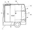
- FIG. 1 is a side view of a vehicle provided with a vehicle door structure according to a first embodiment of the present invention.
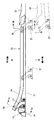
- FIG. 2 is an arrow view along line 2-2 in FIG. 1.
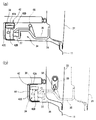
- (A) is a cross-sectional view taken along line 3a-3a in FIG. 2, and (b) is a cross-sectional view taken along line 3b-3b in FIG.
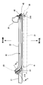
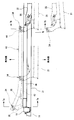
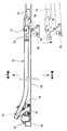
- FIG. 4 is an arrow view along line 4-4 in FIG.
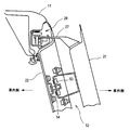
- FIG. 5 is a cross-sectional view taken along line 5-5 in FIG.
- FIG. 6 is a cross-sectional view taken along line 6-6 in FIG.
- (A) is a cross-sectional view taken along line 7a-7a in FIG. 6, and (b) is a cross-sectional view taken along line 7b-7b in FIG.
- FIG. (A) is a side view of the vehicle showing the first door panel in a state of starting to open
- (b) is a side view of the vehicle showing the first door panel in a fully opened state.
- FIG. 1 the left side corresponds to the front of the vehicle, and the right side corresponds to the rear of the vehicle.
- a front door opening 12 located on the side of the front seat and a rear door opening 13 located behind the front seat are formed on the side surface of the vehicle body 11.
- the front door opening 12 is opened and closed by a front door panel 14.
- the front door panel 14 is connected to the vehicle body 11 by a pair of upper and lower hinge mechanisms 15, and the hinge mechanism 15 includes a fulcrum shaft (not shown) extending vertically.
- the front door panel 14 swings around the fulcrum shaft, Open and close the door opening 12.
- a front door lock mechanism 16 is provided between the front door panel 14 and the vehicle body 11.
- the front door lock mechanism 16 connects the front door panel 14 to the vehicle body 11 so as to fully close the front door opening 12.
- the front door lock mechanism 16 includes a latch (not shown) and a door lock striker (not shown), and maintains the front door panel 14 in a fully closed state by connecting the latch and the door lock striker.
- the front door panel 14 By operating the outer handle 17 provided on the outer surface of the front door panel 14, the front door panel 14 in a state where the front door opening 12 is fully closed can be opened from the outside of the vehicle. Further, by operating the inner handle 18 provided on the inner surface of the front door panel 14 (the surface exposed to the vehicle interior), the fully closed front door panel 14 can be opened from the inside of the vehicle.
- the rear door opening 13 is formed on the side of the luggage compartment provided behind the front seat.
- the rear door opening 13 is opened and closed by a vehicle door mechanism including a first door panel 21 that is a slide opening and closing type and a second door panel 22 that is a swing opening and closing type.
- a region where the first door panel 21 is closed is referred to as a first door opening region 13A
- a region where the second door panel 22 is closed is referred to as a second door opening region 13B.
- the first door panel 21 and the second door panel 22 cooperate to open and close the entire rear door opening 13.
- the first door panel 21 slides along the longitudinal direction of the vehicle body 11 to open and close the first door opening area 13A.
- the first door panel 21 is positioned outside the second door panel 22 and overlaps the second door panel 22 in the fully opened state.
- the first door panel 21 moves along the front-rear direction of the vehicle body 11 with respect to the vehicle body 11 and the second door panel 22 via a slide mechanism.
- the slide mechanism includes an upper slide rail 23 as a first slide rail, an intermediate slide rail 40 as a second slide rail, and a lower slide rail 42 as a third slide rail.
- the slide mechanism includes a first guide body 26 guided by the upper slide rail 23, a second guide body 30 guided by the intermediate slide rail 40, and a third guide body 34 guided by the lower slide rail 42. It has.
- the upper arm 27 extends from the position near the front edge of the upper portion of the first door panel 21 toward the vehicle body 11, and the first guide body 26 is provided at the tip of the upper arm 27.
- the first guide body 26 includes a radial roller 28 and a thrust roller 29, and these rollers 28 and 29 are guided along the upper slide rail 23.
- the axis of the rotary shaft of the radial roller 28 extends horizontally, and the axis of the rotary shaft of the thrust roller 29 extends vertically.
- the upper slide rail 23 is provided on the roof side rail ceiling portion of the vehicle body 11 above the first door opening area 13A so as to extend along the upper portion of the fully closed first door panel 21.
- the upper slide rail 23 is a rail that guides the first guide body 26 provided in the first door panel 21, and restricts the first guide body 26 from moving in the vertical direction and the left-right direction of the vehicle body 11.
- the upper slide rail 23 includes a rail upper surface portion 23A, a rail lower surface portion 23B, a rail side surface portion 23C, and a rail outer edge portion 23D, and the cross-sectional shape is a channel shape. is there.
- the radial roller 28 rolls on the rail lower surface portion 23 ⁇ / b> B according to the movement of the first door panel 21.
- the rail side surface portion 23C and the rail outer edge portion 23D restrict the thrust roller 29 from moving in the left-right direction of the vehicle body 11.
- the longitudinal direction of the upper slide rail 23 coincides with the longitudinal direction of the vehicle body 11, and the front end of the upper slide rail 23 is a pillar 19 positioned between the front door panel 14 and the first door panel 21.
- the rear end of the upper slide rail 23 is located near the front edge of the second door panel 22.
- the upper slide rail 23 includes a curved rail portion 24 in a predetermined range near its front end.
- a notched rail portion 25 that does not have the rail outer edge portion 23 ⁇ / b> D is formed at the rear end of the upper slide rail 23.
- the first guide body 26 can be detached from the upper slide rail 23 so as to be separated from the vehicle body 11.
- an intermediate arm 31 extending toward the vehicle body 11 is provided at a portion of the first door panel 21 in the middle portion in the vertical direction and near the rear edge of the first door panel 21.
- the second guide body 30 is provided at the tip of the intermediate arm 31.
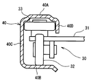
- the second guide body 30 includes a radial roller 32 and a pair of front and rear thrust rollers 33, and the rollers 32 and 33 are guided along the intermediate slide rail 40.
- the thrust roller 33 located in front of the pair of thrust rollers 33 is illustrated.
- the rotational axis of the radial roller 32 extends horizontally, and the rotational axis of the thrust roller 33 extends vertically.
- the intermediate arm 31 is provided so as to be rotatable in the horizontal direction with respect to the first door panel 21 with the rotation shaft 31A as a fulcrum.
- the intermediate slide rail 40 is provided at an intermediate portion in the vertical direction on the outer surface of the second door panel 22, and the longitudinal direction of the intermediate slide rail 40 coincides with the longitudinal direction of the vehicle body 11. As shown in FIG. 4, the front end of the intermediate slide rail 40 is located at the front edge of the second door panel 22, and the rear end of the intermediate slide rail 40 is located at the rear edge of the second door panel 22. That is, the intermediate slide rail 40 is provided so as to cross the outer surface of the second door panel 22 in the front-rear direction.
- the intermediate slide rail 40 is a rail that guides the second guide body 30 provided in the first door panel 21 and restricts the second guide body 30 from moving in the vertical direction and the left-right direction of the vehicle body 11.
- the intermediate slide rail 40 includes a rail upper surface portion 40 ⁇ / b> A, a rail lower surface portion 40 ⁇ / b> B, a rail side surface portion 40 ⁇ / b> C, and a rail outer edge portion 40 ⁇ / b> D.
- the shape is a channel shape.
- the intermediate slide rail 40 includes a curved rail portion 41 in a predetermined range near the front end.
- the second guide body 30 When the first door panel 21, which is in a state of being overlapped with the second door panel 22, is slid toward the front of the vehicle body 11, the second guide body 30 is guided by the curved rail portion 41, whereby the first door panel 21 is The outer surface moves to a position that is flush with the outer surface of the second door panel 22 to close the first door opening area 13A.
- the degree of curvature of the curved rail portion 41 of the intermediate slide rail 40 is set larger than the degree of curvature of the curved rail portion 24 of the upper slide rail 23.
- the lower arm 35 extends from the portion near the front edge of the lower portion of the first door panel 21 toward the vehicle body 11 across the step 36, and the third guide body 34 is It is provided at the tip of the lower arm 35.
- the third guide body 34 includes a radial roller 37 and a thrust roller 38, and the rollers 37 and 38 are guided along the lower slide rail 42.
- the rotational axis of the radial roller 37 extends horizontally, and the rotational axis of the thrust roller 38 extends vertically.
- the lower slide rail 42 is provided at a position near the floor of the vehicle body 11 below the first door opening area 13 ⁇ / b> A so as to extend along the lower portion of the fully closed first door panel 21.
- the lower slide rail 42 is a rail that guides the third guide body 34 of the first door panel 21, and restricts the third guide body 34 from moving in the vertical direction and the horizontal direction of the vehicle body 11.
- the lower slide rail 42 is similar to the upper slide rail 23 in that the rail upper surface portion 42A, the rail lower surface portion 42B, the rail side surface portion 42C, and the rail outer edge. Part 42D.
- the radial roller 37 rolls on the rail lower surface portion 42 ⁇ / b> B according to the movement of the first door panel 21.
- the rail side surface portion 42C and the rail outer edge portion 42D restrict the thrust roller 38 from moving in the left-right direction of the vehicle body 11.
- the longitudinal direction of the lower slide rail 42 coincides with the longitudinal direction of the vehicle body 11, and the front end of the lower slide rail 42 is located in the vicinity of the pillar 19 located between the front door panel 14 and the first door panel 21.
- the rear end of the slide rail 42 is located near the front edge of the second door panel 22.
- the lower slide rail 42 includes a curved rail portion 43 in a predetermined range near the front end.
- a notched rail portion 44 that does not have the rail outer edge portion 42D is formed. In a state where the third guide body 34 is positioned on the notched rail portion 44, the third guide body 34 can be detached from the lower slide rail 42 so as to be separated from the vehicle body 11.
- the second door panel 22 is connected to the vehicle body 11 by a pair of hinge mechanisms 45.
- the hinge mechanism 45 is provided in a portion of the rear pillar 39 corresponding to the intermediate slide rail 40 of the second door panel 22 and a portion corresponding to the lower portion of the second door panel 22.
- the hinge mechanism 45 includes a fulcrum shaft 46 that extends vertically, and the second door panel 22 rotates about the fulcrum shaft 46 as a fulcrum to open and close the rear door opening 13.
- a second door opening / closing restriction mechanism 50 is provided between the second door panel 22 and the vehicle body 11.
- second door opening / closing restriction mechanisms 50 are provided at positions corresponding to the upper and lower portions of the second door panel 22, respectively.
- the second door opening / closing restriction mechanism 50 connects the second door panel 22 to the vehicle body 11 so as to fully close the second door opening area 13B.
- the second door opening / closing regulating mechanism 50 includes a latch (not shown) provided on the second door panel 22 and a door lock striker (not shown) provided on the vehicle body 11, and the connection between the latch and the door lock striker.
- An opening / closing handle 47 is provided at the front edge of the second door panel 22.
- the opening / closing handle 47 By the operation of the opening / closing handle 47, the connection between the second door panel 22 and the vehicle body 11 by the second door opening / closing regulating mechanism 50 is released, whereby the second door panel 22 can be opened / closed.
- the opening / closing handle 47 can be disconnected by the second door opening / closing regulating mechanism 50 only when the first door panel 21 is in a fully open state where it overlaps the second door panel 22 and the second door panel 22 is in a fully closed state. . That is, when the first door panel 21 is in a state other than full open, even if the opening / closing handle 47 is operated, the connection between the second door panel 22 and the vehicle body 11 by the second door opening / closing restriction mechanism 50 is not released.
- a first door opening / closing regulating mechanism 51 is provided between the first door panel 21 and the second door panel 22.
- the first door opening / closing restriction mechanism 51 connects the first door panel 21 in the fully closed state to the second door panel 22.
- the first door opening / closing restriction mechanism 51 includes a latch (not shown) provided at the rear edge of the first door panel 21 and a door lock striker (not shown) provided at the front edge of the second door panel 21.
- An outer handle 48 is provided on the outer surface of the first door panel 21, and an inner handle 49 is provided on the inner surface of the first door panel 21.
- a slide regulating mechanism 52 is provided between the first door panel 21 and the second door panel 22.
- the slide restricting mechanism 52 connects the first door panel 21 in the fully open state overlapping the second door panel 22 to the second door panel 22.
- the slide restricting mechanism 52 includes a latch 53 provided on the first door panel 21 and a door lock striker 54 provided on the second door panel 22.
- the latch 53 and the door striker 54 are connected to each other, whereby the sliding movement of the first door panel 21 with respect to the second door panel 22 is restricted.
- a pair of upper and lower slide restriction mechanisms 52 are installed.
- the slide restriction mechanism 52 has a function of restricting the movement of the first door panel 21 in the vertical direction and the horizontal direction with respect to the second door panel 22.
- the slide restricting mechanism 52 has a function corresponding to a connection lock mechanism that connects the first door panel 21 and the second door panel 22.
- the connection between the first door panel 21 and the second door panel 22 by the slide restriction mechanism 52 is released only when the second door opening / closing restriction mechanism 50 is not released, and the outer handle 48 and the inner door provided on the first door panel 21 are released. It can be performed by operating the handle 49.
- the second door panel 22 is open, the connection between the first door panel 21 and the second door panel 22 by the slide restriction mechanism 52 cannot be released.
- the lower arm 35 is provided with positioning pins 55.
- the tip of the positioning pin 55 is directed to the rear of the vehicle body 11.
- a pin hole 56 that allows insertion of a positioning pin 55 is provided at the front edge end of the second door panel 22.
- the positioning pins 55 are inserted into the pin holes 56. Accordingly, the first door panel 21 is positioned in the vertical direction and the vehicle body 11 in the horizontal direction with respect to the second door panel 22, and the movement of the first door panel 21 in the vertical direction and the vehicle body 11 in the horizontal direction is restricted. Therefore, the positioning pin 55 and the pin hole 56 correspond to a connection lock mechanism that prevents the first door panel 21 from being separated from the second door panel 22 in a direction perpendicular to the sliding direction (the left-right direction of the vehicle body 11).
- the operation of the vehicle door structure of this embodiment will be described.
- the first door panel 21 and the second door panel 22 are fully closed, that is, when the rear door opening 13 is covered by the first door panel 21 and the second door panel 22, the first door panel 21 is fully opened. The case where it does is demonstrated.
- the first door panel 21 shown in FIG. 1 is fully closed, the first door panel 21 is supported by the vehicle body 11 and the second door panel 22.
- the first door opening / closing restriction mechanism 51 is in a state of restricting the sliding movement of the first door panel 21 with respect to the second door panel 22.
- the second door opening / closing restriction mechanism 50 is in a state of restricting the opening / closing of the second door panel 22 with respect to the vehicle body 11.
- the center of gravity G of the first door panel 21 exists substantially at the center of the first door panel 21.
- the outer handle 48 or the inner handle 49 By the operation of the outer handle 48 or the inner handle 49, the connection by the first door opening / closing restriction mechanism 51 is released, and the first door panel 21 slides relative to the second door panel 22 to the rear of the vehicle body 11.
- the first guide body 26 is guided by the upper slide rail 23
- the second guide body 30 is guided by the intermediate slide rail 40
- the third guide body 34 is guided by the lower slide rail 42.
- the guide bodies 26, 30, 34 are guided by the corresponding curved rail portions 24, 41, 43, so that the first door panel 21 slides rearward while facing the outside of the vehicle body 11. Moving.
- the vicinity of the front edge of the first door panel 21 passes through the first guide body 26 and the third guide body 34. 11, the vicinity of the rear edge of the first door panel 21 is connected to the second door panel 22 via the second guide body 30.
- the first guide body 26 guided by the upper slide rail 23 and the second guide body 30 guided by the intermediate slide rail 40 are present on both sides of the center of gravity G of the first door panel 21 in the sliding direction.
- the first guide body 26 and the third guide body 34 are present in front of the center of gravity G of the first door panel 21 and the second guide body 30 is present in the rear of the center of gravity G, the own weight generated in the first door panel 21 Can be received well by the slide rails 23, 40, 42.
- first guide body 26 and the third guide body 34 are present near the front edge of the first door panel 21, and the second guide 30 is present near the rear edge of the first door panel 21. For this reason, for example, even when an external force (in a direction perpendicular to the sliding direction of the first door panel 21) from the vehicle interior to the outside of the vehicle body 11 acts on the first door panel 21 in the state of opening, the first door panel 21 The moment by the external force can be satisfactorily received through the guide bodies 26, 30, and 34 located near the front end edge and the rear end edge of 21, respectively.
- the first door opening area 13 ⁇ / b> A is enlarged while the first door panel 21 overlaps the second door panel 22.
- FIG. 9B when the rearward sliding movement of the first door panel 21 is completed, the first door opening area 13A is maximized, and the first door panel 21 is fully opened.
- the latch 53 provided on the first door panel 21 is coupled to the door lock striker 54 provided on the second door panel 22.
- the connection of the latch 53 and the door lock striker 54 constituting the slide restricting mechanism 52 restricts the sliding movement of the first door panel 21 relative to the second door panel 22.
- the positioning pin 55 provided on the lower arm 35 is inserted into the pin hole 56.
- the first door panel 21 is positioned in the left-right direction with respect to the second door panel 22, and the movement of the first door panel 21 in the left-right direction is restricted.
- the first guide body 26 is not detached from the upper slide rail 23, but is in a detachable state.
- the first guide body 26 is guided by the upper slide rail 23 until the first door panel 21 is fully opened.
- the rail side surface portion 23C and the rail outer edge portion 23D of the upper slide rail 23 restrict the movement of the radial roller 28 in the first guide body 26 in the left-right direction of the vehicle body 11. For this reason, the first guide body 26 is not detached from the upper slide rail 23 until the first door panel 21 is fully opened.
- the first guide body 26 is positioned on the notched rail portion 25 without the rail outer edge portion 23D, and therefore the first guide body 26 is the upper slide. It is in a state where it can be detached from the rail 23. Further, since the notched rail portion 44 is formed on the lower slide rail 42 as well as the upper slide rail 23, the third guide body 34 is in a state where the rearward sliding movement of the first door panel 21 is completely completed. Is detachable from the lower slide rail 42.
- the intermediate slide rail 40 does not include a notch rail portion, the second guide body 30 cannot be detached from the intermediate slide rail 40 even when the first door panel 21 is fully opened.
- the rail outer edge portion 40D prevents the second guide body 30 from being detached.
- the connection between the vehicle body 11 and the second door panel 22 by the second door opening / closing restriction mechanism 50 is released by operating the opening / closing handle 47. Is possible.
- the second door panel 22 can be opened with respect to the vehicle body 11 by shaft rotation about the fulcrum shaft 46 via the hinge mechanism 45.
- the first door panel 21 follows the opening and closing of the second door panel 22 with the first door panel 21 overlapping the second door panel 22.
- the second door panel 22 can be opened at a substantially right angle with respect to the front-rear direction of the vehicle body 11.
- the second door opening area 13B is fully opened.
- the rear door opening 13 is fully opened.
- the first door panel 21 and the second door by the slide restriction mechanism 52 are operated by operating the outer handle 48.
- the connection with the door panel 22 can be released.
- the first door panel 21 is slid forward to enter the fully closed state in which the first door panel 21 closes the first door opening area 13A.
- the first guide body 26 guided by the upper slide rail 23 and the second guide body 30 guided by the intermediate slide rail 40 have a center of gravity G of the first door panel 21 in the sliding direction of the first door panel 21. Further, the third guide body 34 supports the first door panel 21. For this reason, the moment generated in the first door panel 21 can be received not only in the second door panel 22 but also in the vehicle body 11. Therefore, it is not necessary to reinforce the intermediate slide rail 40 and the second door panel 22 in order to reliably receive such a moment, and as a result, the weight of the intermediate slide rail 40 and the second door panel 2 is increased due to such reinforcement. Can be prevented.
- the first guide body 26 When the first door panel 21 is in the fully open state, the first guide body 26 is in a detachable state or a detachable state from the upper slide rail 23. Therefore, the second door panel 22 is connected to the first door panel 21 via the hinge mechanism 45. Axis rotation is possible. Further, even when the first door panel 21 starts to open, the moment due to its own weight generated in the first door panel 21 can be satisfactorily received by the second door panel 22 and the vehicle body 11. Even if a moment due to an external force from the vehicle interior toward the outside of the vehicle body 11 acts on the first door panel 21, the moment can be received well by the second door panel 22 and the vehicle body 11.
- the first guide body 26 of the first door panel 21 is guided by the upper slide rail 23 provided on the vehicle body 11, and the third guide body 34 is guided by the lower slide rail 42 provided on the vehicle body 11,
- the guide body 30 is guided to an intermediate slide rail 40 provided on the second door panel 22. Therefore, since the upper and lower parts of the first door panel 21 are supported by the vehicle body 11 via the first and third guide bodies 26 and 34, the stability of the vehicle body 11 when the first door panel 21 is opened and closed is improved.
- the present embodiment is different from the first embodiment in that a lower slide rail 42 as a third slide rail of the slide mechanism is formed on the second door panel 22.
- members that are the same as those in the first embodiment are denoted by the same reference numerals as those in the first embodiment, and description thereof is omitted.
- the vehicle door structure according to the present embodiment includes a first door panel 60 that is a slide opening and closing type and a second door panel 61 that is a swing opening and closing type.
- an intermediate slide rail 62 as a second slide rail and a lower slide rail 64 as a third slide rail are provided on the second door panel 61.
- the intermediate slide rail 62 has substantially the same configuration as the intermediate slide rail 40 of the first embodiment, and has a rail upper surface portion, a rail lower surface portion, a rail side surface portion, and a rail outer edge portion (not shown). .
- the second guide body 63 guided by the intermediate slide rail 62 has the same configuration as the second guide body 30 of the first embodiment, and is provided at the tip of an intermediate arm (not shown) provided in the second door panel 61. It has been.
- the second guide body 63 includes a radial roller (not shown) and a thrust roller (not shown) that roll within the intermediate slide rail.
- the lower slide rail 64 has the same configuration as the intermediate slide rail 62, and the third guide body 65 guided by the lower slide rail 64 has the same configuration as the second guide body 63. Accordingly, the first door panel 60 is connected to the vehicle body 11 via the first guide body 26 and is connected to the second door panel 61 via the second guide body 63 and the third guide body 65.
- the first door panel 60 can be fully opened by sliding movement, and the second door panel 61 can be opened and closed when the first door panel 60 is fully opened.
- the first guide body 26 of the first door panel 60 is guided by the upper slide rail 23 provided in the vehicle body 11.
- the second guide body 63 is guided by an intermediate slide rail 62 provided on the second door panel 61, and the third guide body 65 is guided by a lower slide rail 64 provided on the second door panel 61.
- the stability to the second door panel 61 when the first door panel 60 is opened and closed is improved. improves.
- the space which installs a lower slide rail in the vehicle body 11 is saved, and the floor in a vehicle interior can be reduced.
- the first guide body 26 is not detached from the upper slide rail 23 (however, , In a state where it can be detached.
- the first guide body 26 is guided to the upper slide rail 72 as the first slide rail.
- the body 73 is completely detached from the upper slide rail 72.
- members that are the same as those in the first embodiment are denoted by the same reference numerals as those in the first embodiment, and description thereof is omitted.
- the vehicle door structure according to the present embodiment includes a first door panel 70 that is a slide opening / closing type and a second door panel 71 that is a swing opening / closing type, as shown in FIG.
- the upper slide rail 72 as the first slide rail is provided on the roof side rail ceiling portion of the vehicle body 11 along the upper portion of the fully closed first door panel 70.
- the upper slide rail 72 guides the first guide body 73 provided at the tip of the upper arm 75 of the first door panel 70 and restricts the movement of the first guide body 73 in the vertical direction and the horizontal direction.
- the upper slide rail 72 includes a rail upper surface portion, a rail lower surface portion, a rail side surface portion, and a rail outer edge portion, like the upper slide rail 23 of the first embodiment.
- the shape is a channel shape.
- the longitudinal direction of the upper slide rail 72 coincides with the longitudinal direction of the vehicle body 11, the front end of the upper slide rail 72 is located near the pillar 19, and the rear end of the upper slide rail 72 is the front edge of the second door panel 71.
- a second door side slide rail 74 is fixed to the second door panel 71 behind the rear end of the upper slide rail 72.
- the second door side slide rail 74 guides the first guide body 73 separated from the rear end of the upper slide rail 72, and the first guide body 73 with respect to the second door panel 71 in the vertical direction and the left and right direction of the vehicle body 11. Restrict movement.
- the second door side slide rail 74 corresponds to a connection lock mechanism that restricts the first door panel 70 from being separated from the second door panel 71 in a direction perpendicular to the sliding direction when the first door panel 70 is fully opened.
- a slide restricting mechanism that restricts the first guide body 73 in the second door side slide rail 74 from sliding in the front-rear direction of the vehicle body 11 is provided.
- the slide restricting mechanism includes a lock plate portion 76 provided on the upper arm 75 and a lock pin 77 provided on the second door side slide rail 74.
- the first guide body 73 when the first door panel 70 is fully opened, the first guide body 73 is detached from the upper slide rail 72 and transferred to the second door side slide rail 74, and the slide movement of the first guide body 73 is a slide restriction. Regulated by mechanism.
- the second door panel 71 can be opened when the first guide body 73 is in a state of being regulated by the slide regulating mechanism.
- the vehicle door structure of the present invention is applied to the vehicle door structure that opens and closes the rear door opening formed on the side of the vehicle body.
- the position of application to the vehicle body For example, you may apply to the door structure which opens and closes the rear side opening part formed in the vehicle body rear surface.
- the weight of the first door panel can be supported by the radial rollers provided in the first to third guide bodies.
- the second weight is Radial rollers 32 and 37 may be provided only on the guide body 30 and the third guide body 34 so that the weight of the first door panel 20 is dispersed and supported by them.
- the first guide body 26 and the second guide body 26 may be supported.
- Radial rollers 32 and 37 may be provided only on the body 30 so that the weight of the first door panel 20 is supported by them.
- the radial rollers 28 and 32 may be provided only on the first guide body 26 and the second guide body 63 so that the weight of the first door panel 60 is dispersed and supported.
- radial rollers guided at least by slide rails provided on the vehicle body 11 are provided on both sides of the center of gravity G of the first door panel 60 in the sliding direction of the first door panel 60, thereby providing the first It is preferable to support the dead weight of the door panel 60.
- the second door side slide rail 74 is provided behind the rear end of the upper slide rail 72.
- the lower slide rail 42 is provided at the lower part of the vehicle body 11, the lower slide rail is provided.
- a second door side slide rail similar to the second door side slide rail 72 is preferably provided behind the rear end of 42. In this case, the upper and lower guide bodies of the first door panel 70 are held by the corresponding second door side slide rails, and the holding state of the first door panel 70 with respect to the second door panel 71 is further stabilized.
- the slide rail may be only the first slide rail provided on the vehicle body 11 and the second slide rail provided on the second door panel.
- the first slide rail is arranged to extend to the upper portion of the second door panel, and the first guide bodies that move along the first slide rail are provided at the front edge end and the rear edge end of the first door panel, respectively.
- the first door panel may be supported by the two first guide bodies and the one second guide body that moves along the second slide rail.
- the first slide rail is provided with a notched rail portion corresponding to each position of the plurality of first guide bodies when the first door panel is fully opened.
- the second slide rail is provided at a position opposite to the first slide rail with respect to the center of gravity G of the first door panel in the second door panel.
- the vehicle type to which the vehicle door structure is applied is not specifically specified.
- the vehicle to which the present invention is applied is, for example, a passenger car having a three-row seat, a luggage transport It may be a freight vehicle having a loading platform.
- passengers can get on and off without moving the last row of seats by fully opening the first and second door panels.
- the back door is opened and closed by fully opening the first and second door panels even for a large load that conventionally required opening and closing of the back door to load and unload the load. It is possible to load and unload luggage without any problems.
- G center of gravity of first door panel, 11: vehicle body, 13: rear door opening, 13A: first door opening area, 13B: second door opening area, 21, 60, 70 ... first door panel, 22, 61, 71 ... 2nd door panel, 23, 72 ... Upper slide rail (first slide rail), 26, 73 ... 1st guide body, 30, 63 ... 2nd guide body, 34, 65 ... 3rd guide body, 40, 62 ... Intermediate slide rail (second slide rail), 42, 64 ... lower slide rail (third slide rail), 45 ... hinge mechanism, 50 ... second door opening / closing restriction mechanism, 51 ... first door opening / closing restriction mechanism, 52 ... slide Restriction mechanism, 55 ... positioning pin (connection lock mechanism), 56 ... pin hole (connection lock mechanism), 74 ... second door side slide rail, 76 ... lock plate portion, 77 ... pin.
Landscapes
- Engineering & Computer Science (AREA)
- Mechanical Engineering (AREA)
- Support Devices For Sliding Doors (AREA)
- Lock And Its Accessories (AREA)
Priority Applications (3)
| Application Number | Priority Date | Filing Date | Title |
|---|---|---|---|
| EP10811817.5A EP2471678B1 (en) | 2009-08-27 | 2010-08-23 | Vehicle door structure |
| US13/391,986 US8567126B2 (en) | 2009-08-27 | 2010-08-23 | Vehicle door structure having a slide mechanism |
| CN201080037190.4A CN102481828B (zh) | 2009-08-27 | 2010-08-23 | 车门构造 |
Applications Claiming Priority (2)
| Application Number | Priority Date | Filing Date | Title |
|---|---|---|---|
| JP2009-196170 | 2009-08-27 | ||
| JP2009196170A JP5644076B2 (ja) | 2009-08-27 | 2009-08-27 | 車両用ドア構造 |
Publications (1)
| Publication Number | Publication Date |
|---|---|
| WO2011024767A1 true WO2011024767A1 (ja) | 2011-03-03 |
Family
ID=43627872
Family Applications (1)
| Application Number | Title | Priority Date | Filing Date |
|---|---|---|---|
| PCT/JP2010/064204 Ceased WO2011024767A1 (ja) | 2009-08-27 | 2010-08-23 | 車両用ドア構造 |
Country Status (5)
| Country | Link |
|---|---|
| US (1) | US8567126B2 (enExample) |
| EP (1) | EP2471678B1 (enExample) |
| JP (1) | JP5644076B2 (enExample) |
| CN (1) | CN102481828B (enExample) |
| WO (1) | WO2011024767A1 (enExample) |
Cited By (5)
| Publication number | Priority date | Publication date | Assignee | Title |
|---|---|---|---|---|
| FR2968604A1 (fr) * | 2010-12-10 | 2012-06-15 | Peugeot Citroen Automobiles Sa | Vehicule automobile comportant une porte laterale avant pivotante integree a une porte laterale arriere pivotante. |
| CN103253110A (zh) * | 2012-02-17 | 2013-08-21 | 株式会社丰田自动织机 | 车门构造 |
| EP2786883A4 (en) * | 2011-11-29 | 2015-04-08 | Toyota Jidoshokki Kk | VEHICLE DOOR STRUCTURE |
| EP2517912A3 (en) * | 2011-04-26 | 2015-11-04 | Nissan Motor Manufacturing (UK) Ltd. | Improvements in or relating to doors |
| JP2018096096A (ja) * | 2016-12-13 | 2018-06-21 | 株式会社巴コーポレーション | 電波吸収衝立の開閉機構 |
Families Citing this family (37)
| Publication number | Priority date | Publication date | Assignee | Title |
|---|---|---|---|---|
| JP5440592B2 (ja) * | 2011-11-29 | 2014-03-12 | 株式会社豊田自動織機 | 車両用ドア構造 |
| JP2013180746A (ja) * | 2012-03-05 | 2013-09-12 | Toyota Industries Corp | 車両用ドア構造 |
| JP5633543B2 (ja) | 2012-07-27 | 2014-12-03 | 株式会社豊田自動織機 | 車両用ドア構造 |
| JP5617876B2 (ja) | 2012-08-10 | 2014-11-05 | 株式会社豊田自動織機 | 車両用ドア構造 |
| ITTO20120754A1 (it) * | 2012-08-31 | 2014-03-01 | Coproget S R L | Guida per una porta scorrevole, in particolare di un veicolo, e relativo metodo di realizzazione |
| JP2014061766A (ja) * | 2012-09-20 | 2014-04-10 | Toyota Industries Corp | 車両用ドア構造 |
| US8819993B1 (en) * | 2013-03-06 | 2014-09-02 | Nien Made Enterprise Co., Ltd. | Covering of building's opening |
| JP2014184815A (ja) * | 2013-03-22 | 2014-10-02 | Toyota Industries Corp | 車両用ドア構造 |
| JP5880480B2 (ja) | 2013-04-17 | 2016-03-09 | 株式会社豊田自動織機 | 車両用ドア構造 |
| JP6252180B2 (ja) * | 2014-01-09 | 2017-12-27 | 株式会社豊田自動織機 | 車両用ドア構造 |
| US20160082815A1 (en) * | 2014-09-23 | 2016-03-24 | Hyundai Motor Company | Gull wing door with slide door for vehicle |
| JP2016084078A (ja) * | 2014-10-28 | 2016-05-19 | 株式会社豊田自動織機 | 車両用ドア構造 |
| JP6252498B2 (ja) * | 2015-01-08 | 2017-12-27 | 株式会社豊田自動織機 | 車両用ドア構造 |
| JP6237679B2 (ja) | 2015-03-19 | 2017-11-29 | 株式会社豊田自動織機 | 車両用ドア構造 |
| JP6156420B2 (ja) | 2015-03-19 | 2017-07-05 | 株式会社豊田自動織機 | 車両用ドア構造 |
| JP2016175522A (ja) | 2015-03-19 | 2016-10-06 | 株式会社豊田自動織機 | 車両用ドア構造 |
| JP2016215857A (ja) | 2015-05-21 | 2016-12-22 | 株式会社豊田自動織機 | 車両用ドア構造 |
| US10518616B2 (en) * | 2017-07-31 | 2019-12-31 | Riad M. Houmani | Sliding and pivoting door combination assembly for a vehicle |
| US10415289B2 (en) | 2017-08-21 | 2019-09-17 | French Slide Llc | Door system with sliding and hinging capability |
| CN111344170B (zh) * | 2017-11-17 | 2023-06-02 | 沃尔沃汽车公司 | 舱盖操作机构 |
| KR102644310B1 (ko) * | 2019-01-24 | 2024-03-07 | 현대자동차주식회사 | 차량용 도어의 실링 구조 |
| US11220852B2 (en) * | 2019-05-02 | 2022-01-11 | Textron Innovations Inc. | Aircraft having versatile door systems |
| US11585137B2 (en) * | 2019-07-02 | 2023-02-21 | The Braun Corporation | Modified door operation for a motorized vehicle |
| GB2586047B (en) * | 2019-07-31 | 2022-05-25 | Thermo Fisher Scient Bremen Gmbh | A sliding door assembly for an ICP torch box |
| CA3094912A1 (en) | 2019-09-30 | 2021-03-30 | Driverge Vehicle Innovations, Llc | Retrofit rear curbside door for vehicle |
| KR20210055827A (ko) * | 2019-11-07 | 2021-05-18 | 현대자동차주식회사 | 차량의 슬라이딩/스윙 복합도어 |
| US11808065B2 (en) * | 2019-11-07 | 2023-11-07 | Hyundai Motor Company | Sliding/swing composite door for vehicle |
| KR102908996B1 (ko) * | 2019-11-12 | 2026-01-08 | 현대자동차주식회사 | 차량도어 개폐장치 |
| KR102692335B1 (ko) * | 2019-12-05 | 2024-08-07 | 현대자동차주식회사 | 차량도어 개폐장치 |
| KR102739179B1 (ko) * | 2019-12-05 | 2024-12-06 | 현대자동차주식회사 | 차량도어 체크기구 및 이를 포함하는 차량도어 개폐장치 |
| KR102791559B1 (ko) * | 2019-12-10 | 2025-04-03 | 현대자동차주식회사 | 양방향 도어 개방모듈 |
| KR102817479B1 (ko) * | 2019-12-10 | 2025-06-05 | 현대자동차주식회사 | 양방향 도어 개방구조 |
| KR102791270B1 (ko) * | 2020-09-21 | 2025-04-08 | 현대자동차주식회사 | 차량도어 개폐장치 |
| US11926198B2 (en) | 2021-10-14 | 2024-03-12 | Ford Global Technologies, Llc | Side door for a vehicle |
| KR20230086371A (ko) * | 2021-12-08 | 2023-06-15 | 현대자동차주식회사 | 도어 닫힘 충격 흡수 장치 및 이를 포함하는 도어 매커니즘 |
| CN116411746B (zh) * | 2021-12-30 | 2024-10-29 | 比亚迪股份有限公司 | 车门控制方法与装置、车辆、计算机存储介质 |
| US20240300596A1 (en) * | 2023-03-07 | 2024-09-12 | Winnebago Industries, Inc. | Door designs for recreational vehicles |
Citations (4)
| Publication number | Priority date | Publication date | Assignee | Title |
|---|---|---|---|---|
| JPH10147149A (ja) * | 1996-11-18 | 1998-06-02 | Isono Body:Kk | 貨物車両の箱型荷室用自動開閉扉 |
| FR2818591A1 (fr) * | 2000-12-27 | 2002-06-28 | Peugeot Citroen Automobiles Sa | Systeme d'ouvrants, notamment pour vehicule automobile |
| JP2004528216A (ja) * | 2001-04-05 | 2004-09-16 | インヴェニオ・ゲゼルシャフト・ミット・ベシュレンクテル・ハフツング・エンジニアリング・サーヴィシーズ | 滑車およびスライドレールを備える自動車用スライドドアガイド |
| JP2006240611A (ja) | 2005-03-03 | 2006-09-14 | Arvinmeritor Technology Llc | 車両用ドアシステム |
Family Cites Families (18)
| Publication number | Priority date | Publication date | Assignee | Title |
|---|---|---|---|---|
| GB2082660B (en) * | 1980-08-30 | 1984-03-28 | Nissan Motor | Sliding plug door for a vehicle |
| JPH0645596Y2 (ja) * | 1988-02-24 | 1994-11-24 | 松下電工株式会社 | 引戸の開閉構造 |
| JP3201717B2 (ja) * | 1996-02-26 | 2001-08-27 | 松下電工株式会社 | スライディングドアの構造 |
| DE19634369C1 (de) * | 1996-08-26 | 1997-09-18 | Daimler Benz Ag | Vorrichtung zum Führen einer ausschwenkbaren Schiebetür an einer Fahrzeugkarosserie |
| US7438346B1 (en) * | 1997-03-17 | 2008-10-21 | Automotive Technologies International, Inc. | Method and apparatus for controlling a vehicle door |
| AT405155B (de) * | 1997-04-28 | 1999-06-25 | Ife Gmbh | Schwenkschiebetür für fahrzeuge |
| JP3452009B2 (ja) * | 1999-12-22 | 2003-09-29 | トヨタ車体株式会社 | スライドドアのセンターレール取付け構造 |
| US6422287B1 (en) * | 2000-07-10 | 2002-07-23 | James Bradley Wilke | Slide/swing patio door |
| US6471284B2 (en) * | 2001-03-05 | 2002-10-29 | General Motors Corporation | Rear end closure assembly for an automotive vehicle |
| US20030218358A1 (en) * | 2002-05-24 | 2003-11-27 | Seonho Hahn | Dual mode vehicle side door |
| DE10332026A1 (de) * | 2003-07-15 | 2005-02-03 | Daimlerchrysler Ag | Türanordnung für ein Kraftfahrzeug |
| DE10333834A1 (de) * | 2003-07-24 | 2005-08-11 | Igus Spritzgussteile für die Industrie GmbH | Schiebetürensystem |
| JP4645800B2 (ja) * | 2004-07-02 | 2011-03-09 | マツダ株式会社 | 自動車の側部構造 |
| US7073847B2 (en) * | 2004-09-10 | 2006-07-11 | Oshkosh Truck Corporation | Duplex door for vehicle |
| FR2877899B1 (fr) * | 2004-11-15 | 2008-06-06 | Renault Sas | Ensemble de structure de caisse de vehicule automobile comportant un ouvrant compact |
| US7097229B1 (en) * | 2005-05-12 | 2006-08-29 | Gm Global Technology Operations, Inc. | Vehicle closure system |
| JP4434273B2 (ja) * | 2007-11-30 | 2010-03-17 | 三菱自動車工業株式会社 | 車体構造 |
| CA2752721C (en) * | 2010-09-17 | 2018-12-04 | Stanley Black & Decker, Inc. | Slide door |
-
2009
- 2009-08-27 JP JP2009196170A patent/JP5644076B2/ja not_active Expired - Fee Related
-
2010
- 2010-08-23 US US13/391,986 patent/US8567126B2/en not_active Expired - Fee Related
- 2010-08-23 WO PCT/JP2010/064204 patent/WO2011024767A1/ja not_active Ceased
- 2010-08-23 CN CN201080037190.4A patent/CN102481828B/zh not_active Expired - Fee Related
- 2010-08-23 EP EP10811817.5A patent/EP2471678B1/en not_active Not-in-force
Patent Citations (4)
| Publication number | Priority date | Publication date | Assignee | Title |
|---|---|---|---|---|
| JPH10147149A (ja) * | 1996-11-18 | 1998-06-02 | Isono Body:Kk | 貨物車両の箱型荷室用自動開閉扉 |
| FR2818591A1 (fr) * | 2000-12-27 | 2002-06-28 | Peugeot Citroen Automobiles Sa | Systeme d'ouvrants, notamment pour vehicule automobile |
| JP2004528216A (ja) * | 2001-04-05 | 2004-09-16 | インヴェニオ・ゲゼルシャフト・ミット・ベシュレンクテル・ハフツング・エンジニアリング・サーヴィシーズ | 滑車およびスライドレールを備える自動車用スライドドアガイド |
| JP2006240611A (ja) | 2005-03-03 | 2006-09-14 | Arvinmeritor Technology Llc | 車両用ドアシステム |
Non-Patent Citations (1)
| Title |
|---|
| See also references of EP2471678A4 * |
Cited By (8)
| Publication number | Priority date | Publication date | Assignee | Title |
|---|---|---|---|---|
| FR2968604A1 (fr) * | 2010-12-10 | 2012-06-15 | Peugeot Citroen Automobiles Sa | Vehicule automobile comportant une porte laterale avant pivotante integree a une porte laterale arriere pivotante. |
| EP2517912A3 (en) * | 2011-04-26 | 2015-11-04 | Nissan Motor Manufacturing (UK) Ltd. | Improvements in or relating to doors |
| EP2786883A4 (en) * | 2011-11-29 | 2015-04-08 | Toyota Jidoshokki Kk | VEHICLE DOOR STRUCTURE |
| US9079477B2 (en) | 2011-11-29 | 2015-07-14 | Kabushiki Kaisha Toyota Jidoshokki | Vehicle door structure |
| CN103253110A (zh) * | 2012-02-17 | 2013-08-21 | 株式会社丰田自动织机 | 车门构造 |
| EP2628618A3 (en) * | 2012-02-17 | 2015-04-15 | Kabushiki Kaisha Toyota Jidoshokki | Vehicle door structure |
| US9074398B2 (en) | 2012-02-17 | 2015-07-07 | Kabushiki Kaisha Toyota Jidoshokki | Vehicle door structure |
| JP2018096096A (ja) * | 2016-12-13 | 2018-06-21 | 株式会社巴コーポレーション | 電波吸収衝立の開閉機構 |
Also Published As
| Publication number | Publication date |
|---|---|
| JP5644076B2 (ja) | 2014-12-24 |
| US20120167468A1 (en) | 2012-07-05 |
| EP2471678B1 (en) | 2017-06-14 |
| JP2011046271A (ja) | 2011-03-10 |
| EP2471678A4 (en) | 2015-04-22 |
| US8567126B2 (en) | 2013-10-29 |
| CN102481828B (zh) | 2015-04-01 |
| CN102481828A (zh) | 2012-05-30 |
| EP2471678A1 (en) | 2012-07-04 |
Similar Documents
| Publication | Publication Date | Title |
|---|---|---|
| JP5644076B2 (ja) | 車両用ドア構造 | |
| US7798557B2 (en) | Vehicle unguided four-bar rear door articulating and sliding mechanism | |
| JP2011046271A5 (enExample) | ||
| JP2014061766A (ja) | 車両用ドア構造 | |
| US11186369B2 (en) | Pivotable luggage locker, and vehicle having a luggage locker | |
| JP7767902B2 (ja) | 車両用ドア装置 | |
| JP2001105877A (ja) | キャブリオレ用折畳みトップ | |
| US20130227887A1 (en) | Vehicle door structure | |
| CN115071382B (zh) | 滑动门构造 | |
| EP1849650B1 (en) | Rear baggage compartment structure | |
| JP2003026046A (ja) | 自動車のボデー構造 | |
| JP5447324B2 (ja) | 車両用ドア構造 | |
| CN101445033B (zh) | 车身结构 | |
| US20070252401A1 (en) | Rear baggage compartment structure of vehicle | |
| JP4544138B2 (ja) | スイングスライドドア | |
| JP4428346B2 (ja) | 車体構造 | |
| JP2001317269A (ja) | スライドドアの支持構造 | |
| JP2003148024A (ja) | 自動車のドアロック装置 | |
| JP2007145092A (ja) | 車体構造 | |
| JP2000301948A (ja) | 自動車用開口ルーフ構造 | |
| JP5440592B2 (ja) | 車両用ドア構造 | |
| JP2008094344A (ja) | ドアの補強構造 | |
| JP2010095234A (ja) | スイングスライドドア構造 | |
| JP4134618B2 (ja) | 車両のスライドドア構造 | |
| JP5625784B2 (ja) | 車両のオープンルーフ構造 |
Legal Events
| Date | Code | Title | Description |
|---|---|---|---|
| WWE | Wipo information: entry into national phase |
Ref document number: 201080037190.4 Country of ref document: CN |
|
| 121 | Ep: the epo has been informed by wipo that ep was designated in this application |
Ref document number: 10811817 Country of ref document: EP Kind code of ref document: A1 |
|
| DPE1 | Request for preliminary examination filed after expiration of 19th month from priority date (pct application filed from 20040101) | ||
| REEP | Request for entry into the european phase |
Ref document number: 2010811817 Country of ref document: EP |
|
| WWE | Wipo information: entry into national phase |
Ref document number: 13391986 Country of ref document: US Ref document number: 2010811817 Country of ref document: EP |
|
| NENP | Non-entry into the national phase |
Ref country code: DE |