EP2471678B1 - Vehicle door structure - Google Patents
Vehicle door structure Download PDFInfo
- Publication number
- EP2471678B1 EP2471678B1 EP10811817.5A EP10811817A EP2471678B1 EP 2471678 B1 EP2471678 B1 EP 2471678B1 EP 10811817 A EP10811817 A EP 10811817A EP 2471678 B1 EP2471678 B1 EP 2471678B1
- Authority
- EP
- European Patent Office
- Prior art keywords
- door panel
- door
- slide rail
- guide body
- vehicle
- Prior art date
- Legal status (The legal status is an assumption and is not a legal conclusion. Google has not performed a legal analysis and makes no representation as to the accuracy of the status listed.)
- Not-in-force
Links
Images


Classifications
-
- E—FIXED CONSTRUCTIONS
- E05—LOCKS; KEYS; WINDOW OR DOOR FITTINGS; SAFES
- E05D—HINGES OR SUSPENSION DEVICES FOR DOORS, WINDOWS OR WINGS
- E05D15/00—Suspension arrangements for wings
- E05D15/56—Suspension arrangements for wings with successive different movements
- E05D15/58—Suspension arrangements for wings with successive different movements with both swinging and sliding movements
-
- B—PERFORMING OPERATIONS; TRANSPORTING
- B60—VEHICLES IN GENERAL
- B60J—WINDOWS, WINDSCREENS, NON-FIXED ROOFS, DOORS, OR SIMILAR DEVICES FOR VEHICLES; REMOVABLE EXTERNAL PROTECTIVE COVERINGS SPECIALLY ADAPTED FOR VEHICLES
- B60J5/00—Doors
- B60J5/04—Doors arranged at the vehicle sides
- B60J5/06—Doors arranged at the vehicle sides slidable; foldable
-
- E—FIXED CONSTRUCTIONS
- E05—LOCKS; KEYS; WINDOW OR DOOR FITTINGS; SAFES
- E05D—HINGES OR SUSPENSION DEVICES FOR DOORS, WINDOWS OR WINGS
- E05D15/00—Suspension arrangements for wings
- E05D15/06—Suspension arrangements for wings for wings sliding horizontally more or less in their own plane
- E05D15/10—Suspension arrangements for wings for wings sliding horizontally more or less in their own plane movable out of one plane into a second parallel plane
- E05D15/1042—Suspension arrangements for wings for wings sliding horizontally more or less in their own plane movable out of one plane into a second parallel plane with transversely moving carriage
- E05D2015/1055—Suspension arrangements for wings for wings sliding horizontally more or less in their own plane movable out of one plane into a second parallel plane with transversely moving carriage with slanted or curved track sections or cams
-
- E—FIXED CONSTRUCTIONS
- E05—LOCKS; KEYS; WINDOW OR DOOR FITTINGS; SAFES
- E05Y—INDEXING SCHEME RELATING TO HINGES OR OTHER SUSPENSION DEVICES FOR DOORS, WINDOWS OR WINGS AND DEVICES FOR MOVING WINGS INTO OPEN OR CLOSED POSITION, CHECKS FOR WINGS AND WING FITTINGS NOT OTHERWISE PROVIDED FOR, CONCERNED WITH THE FUNCTIONING OF THE WING
- E05Y2800/00—Details, accessories and auxiliary operations not otherwise provided for
- E05Y2800/10—Additional functions
- E05Y2800/122—Telescopic action
-
- E—FIXED CONSTRUCTIONS
- E05—LOCKS; KEYS; WINDOW OR DOOR FITTINGS; SAFES
- E05Y—INDEXING SCHEME RELATING TO HINGES OR OTHER SUSPENSION DEVICES FOR DOORS, WINDOWS OR WINGS AND DEVICES FOR MOVING WINGS INTO OPEN OR CLOSED POSITION, CHECKS FOR WINGS AND WING FITTINGS NOT OTHERWISE PROVIDED FOR, CONCERNED WITH THE FUNCTIONING OF THE WING
- E05Y2900/00—Application of doors, windows, wings or fittings thereof
- E05Y2900/50—Application of doors, windows, wings or fittings thereof for vehicles
- E05Y2900/53—Application of doors, windows, wings or fittings thereof for vehicles characterised by the type of wing
- E05Y2900/531—Doors
Definitions
- the present invention relates to a vehicle door structure, and particularly to a vehicle door structure having a composite door in which a sliding door and a swing door are combined.
- Patent Document 1 As a prior-art vehicle door structure, a vehicle door system disclosed in Patent Document 1 is known, for example.
- the vehicle door system in Patent Document 1 has a first door panel and a second door panel, and the first door panel and the second door panel collaborate with each other and close a door opening in a vehicle body.
- the first door panel is relatively moved with respect to the second door panel and opens/closes a part of the door opening.
- the first door panel and the second door panel are relatively moved with respect to the vehicle body to open and close the whole of the door opening.
- the first door panel slides in the horizontal direction along a pair of slide tracks provided on an upper part and a lower part of the second door panel.
- the second door panel is connected to the vehicle body through a hinge assembly, and the second door panel is rotatable around a vertical axis with respect to the vehicle body by using the hinge assembly as a fulcrum.
- Patent Document 2 discloses a vehicular opening system according to the preamble of claim 1, which consists of at least a primary and secondary door, mounted to move, relative to a frame, between two extreme positions of open and closed.
- the primary door is mounted to pivot on the base and the secondary door is mounted to slide, relative to the primary door, between a closed position, when it is applied against the frame and extends the line of the primary door, and an open position, where it is located alongside the primary door.
- the first door panel is supported by the slide tracks provided on the second door panel and slides between the fully open position where the first door panel substantially overlap the second door panel and a fully closed position extended in the horizontal direction from the second door panel along the slide tracks. While the first door panel in the fully closed position begins to be moved toward the fully open position, the first door panel is supported by the slide tracks at a portion on one end side in the sliding direction, that is, at a portion far from the center of gravity of the first door panel in the sliding direction. Thus, in the first door panel, a moment around the horizontal axis is generated by the weight of the first door panel.
- first door panel in the fully closed position begins to be moved toward the fully open position
- an external force is applied to the first door panel from the vehicle interior to the outside of the vehicle body
- a moment around the vertical axis occurs in the first door panel.
- rigidity of the slide tracks or the second door panel should be improved.
- the slide tracks and the second door panel are reinforced in order to improve the rigidity thereof, the weights of the first door panel and the second door panel are increased, and opening/closing of these door panels become difficult.
- An objective of the present invention is to provide a vehicle door structure in which a part of or the whole of the door opening can be opened/closed by a sliding type first door panel and a swing type second door panel and has rigidity higher than the prior-art doors.
- a vehicle door structure according to claim 1 is provided.
- a vehicle door structure according to a first embodiment of the present invention will be described below by referring to the attached drawings.
- the vehicle door structure of this embodiment is applied to a side part of a vehicle body 11.
- the left side corresponds to the front of the vehicle and the right side corresponds to the rear of the vehicle.
- a front door opening 12 located on the side of the front seats and a rear door opening 13 located on the rear of the front seats are formed on the side face of the vehicle body 11.
- the front door opening 12 is opened and closed by a front door panel 14.
- the front door panel 14 is connected to the vehicle body 11 by a pair of upper and lower hinge mechanisms 15.
- the hinge mechanisms 15 are provided with a fulcrum shaft (not shown) extending vertically.
- the front door panel 14 swings around the fulcrum shaft as the center and opens/closes the front door opening 12.
- a front door lock mechanism 16 is provided between the front door panel 14 and the vehicle body 11.
- the front door lock mechanism 16 connects the front door panel 14 to the vehicle body 11 and fully closes the front door opening 12.
- the front door lock mechanism 16 is provided with a latch (not shown) and a door lock striker (not shown) and keeps the front door panel 14 in the fully closed state by means of connection between the latch and the door lock striker.
- the front door panel 14, which fully closes the front door opening 12 can be opened from outside the vehicle by operating an outer handle 17 provided on the outer face of the front door panel 14. Also, the front door panel 14 in the fully closed state can be opened from inside the vehicle by operating an inner handle 18 provided on the inner face (face exposed into the vehicle interior) of the front door panel 14.
- the rear door opening 13 is formed on the side of a luggage compartment provided in the rear of the front seats.
- the rear door opening 13 is opened and closed by a vehicle door mechanism provided with a slide opening/closing type first door panel 21 and a swing opening/closing type second door panel 22.
- a region closed by the first door panel 21 is referred to as a first door opening region 13A
- a region closed by the second door panel 22 is referred to as a second door opening region 13B.
- the first door panel 21 and the second door panel 22 collaborate with each other to open/close the whole rear door opening 13.
- the first door panel 21 slides in the front-rear direction of the vehicle body 11 and opens/closes the first door opening region 13A.
- the first door panel 21 is located outside the second door panel 22 in the fully open state and overlaps the second door panel 22.
- the first door panel 21 moves in the front-rear direction of the vehicle body 11 with respect to the vehicle body 11 and the second door panel 22 through the slide mechanism.
- the slide mechanism is provided with an upper slide rail 23 as a first slide rail, an intermediate slide rail 40 as a second slide rail, and a lower slide rail 42 as a third slide rail. Also, the slide mechanism is provided with a first guide body 26 guided by the upper slide rail 23, a second guide body 30 guided by the intermediate slide rail 40, and a third guide body 34 guided by the lower slide rail 42. As illustrated in Fig. 2 , an upper arm 27 extends from a position close to the front edge on the upper part of the first door panel 21 toward the vehicle body 11, and the first guide body 26 is provided at the distal end of this upper arm 27. As illustrated in Figs.
- the first guide body 26 is provided with a radial roller 28 and a thrust roller 29, and the rollers 28 and 29 are guided along the upper slide rail 23.
- the rotational axis of the radial roller 28 extends horizontally, and the rotational axis of the thrust roller 29 extends vertically.
- the upper slide rail 23 is provided on a roof side rail ceiling portion of the vehicle body 11 located above the first door opening region 13A and extends along the upper part of the first door panel 21 in the fully closed state.
- the upper slide rail 23 is a rail that guides the first guide body 26 provided in the first door panel 21 and restricts movement of the first guide body 26 in the up-down direction and the left-right direction of the vehicle body 11.
- the upper slide rail 23 is provided with a rail upper face portion 23A, a rail lower face portion 23B, a rail side face portion 23C, and a rail outer edge portion 23D, and the shape of a cross-section is a channel shape.
- the radial roller 28 rolls on the rail lower face portion 23B in accordance with the movement of the first door panel 21.
- the rail side face portion 23C and the rail outer edge portion 23D restrict the movement of the thrust roller 29 in the left-right direction of the vehicle body 11.
- the longitudinal direction of the upper slide rail 23 matches the front-rear direction of the vehicle body 11.
- the front end of the upper slide rail 23 is located in the vicinity of a pillar 19 located between the front door panel 14 and the first door panel 21.
- the rear end of the upper slide rail 23 is located in the vicinity of the front edge of the second door panel 22.
- the upper slide rail 23 is provided with a curved rail portion 24 in a predetermined range close to the front end.
- the first guide body 26 is guided by the curved rail portion 24, and thus the first door panel 21 is moved to a position where the outer face thereof becomes flush with the outer face of the second door panel 22 and closes the first door opening region 13A.
- a cutout rail portion 25 not having a rail outer edge portion 23D is formed. While the first guide body 26 is located in the cutout rail portion 25, the first guide body 26 can be removed from the upper slide rail 23 and scan be separated from the vehicle body 11.
- an intermediate arm 31 extending toward the vehicle body 11 is provided in an intermediate portion in the up-down direction of the first door panel 21 and close to the rear edge of the first door panel 21.
- the second guide body 30 is provided at the distal end of this intermediate arm 31.
- the second guide body 30 is provided with a radial roller 32 and a pair of front and rear thrust rollers 33, and the rollers 32 and 33 are guided along the intermediate slide rail 40.
- the thrust roller 33 located in the front in the pair of thrust rollers 33 is illustrated.
- the rotational axis of the radial roller 32 extends horizontally, and the rotational axis of the thrust rollers 33 extends vertically.
- the intermediate arm 31 is provided rotatably in the left-right direction with respect to the first door panel 21 with a rotary shaft 31A as a fulcrum.
- the intermediate slide rail 40 is provided in an intermediate portion in the up-down direction on the outer face of the second door panel 22, and the longitudinal direction of the intermediate slide rail 40 matches the front-rear direction of the vehicle body 11. As illustrated in Fig. 4 , the front end of the intermediate slide rail 40 is located at the front edge of the second door panel 22, and the rear end of the intermediate slide rail 40 is located at the rear edge of the second door panel 22. That is, the intermediate slide rail 40 is provided to cross the outer face of the second door panel 22 in the front-rear direction.
- the intermediate slide rail 40 is a rail that guides the second guide body 30 provided in the first door panel 21 and restricts the movement of the second guide body 30 in the up-down direction and the left-right direction of the vehicle body 11.
- the intermediate slide rail 40 is provided with a rail upper face portion 40A, a rail lower face portion 40B, a rail side face portion 40C, and a rail outer edge portion 40D similarly to the upper slide rail 23, and the shape of the cross-section is a channel shape.
- the intermediate slide rail 40 is provided with a curved rail portion 41 in a predetermined range close to the front end thereof.
- the second guide body 30 is guided along the curved rail portion 41, and the first door panel 21 is moved to a position where the outer face thereof becomes flush with the outer face of the second door panel 22 and closes the first door opening region 13A.
- the curvature of the curved rail portion 41 of the intermediate slide rail 40 is set larger than the curvature of the curved rail portion 24 of the upper slide rail 23.
- the second guide body 30 is smoothly moved in the intermediate slide rail 40 including the curved rail portion 41 by means of rotation of the intermediate arm 31 with respect to the second door panel 22.
- a lower arm 35 extends from a portion close to the front edge of the lower part of the first door panel 21 toward the vehicle body 11 across a step 36, and the third guide body 34 is provided at the distal end of the lower arm 35.
- the third guide body 34 is provided with a radial roller 37 and a thrust roller 38, and the rollers 37 and 38 are guided along the lower slide rail 42.
- the rotational axis of the radial roller 37 extends horizontally, and the rotational axis of the thrust roller 38 extends vertically.
- the lower slide rail 42 is provided at a position close to the floor of the vehicle body 11 on the lower side of the first door opening region 13A to follow the lower part of the first door panel 21 in the fully closed state.
- the lower slide rail 42 is a rail that guides the third guide body 34 of the first door panel 21 and restricts the movement of the third guide body 34 in the up-down direction and the left-right direction of the vehicle body 11.
- the lower slide rail 42 is provided with a rail upper face portion 42A, a rail lower face portion 42B, a rail side face portion 42C, and a rail outer edge portion 42D similarly to the upper slide rail 23.
- the radial roller 37 rolls on the rail lower face portion 42B in accordance with the movement of the first door panel 21.
- the rail side face portion 42C and the rail outer edge portion 42D restrict the movement of the thrust roller 38 in the left-right direction of the vehicle body 11.
- the longitudinal direction of the lower slide rail 42 matches the front-rear direction of the vehicle body 11, and the front end of the lower slide rail 42 is located in the vicinity of the pillar 19 located between the front door panel 14 and the first door panel 21, and the rear end of the lower slide rail 42 is located in the vicinity of the front edge of the second door panel 22.
- the lower slide rail 42 is provided with a curved rail portion 43 in a predetermined range close to the front end thereof.
- a cutout rail portion 44 not having the rail outer edge portion 42D is formed.
- the third guide body 34 can be removed from the lower slide rail 42 and separated from the vehicle body 11 while the third guide body 34 is located in the cutout rail portion 44.
- the second door panel 22 is connected to the vehicle body 11 by a pair of hinge mechanisms 45.
- the hinge mechanisms 45 are provided at a portion corresponding to the intermediate slide rail 40 of the second door panel 22 and a portion corresponding to the lower part of the second door panel 22 in a rear pillar 39.
- the second door panel 22 is rotatable with respect to the vehicle body 11 through the hinge mechanisms 45 in a state in which the first door panel 21 is fully open and overlapped with the second door panel 22.
- the hinge mechanism 45 is provided with a fulcrum shaft 46 extending vertically, and the second door panel 22 is axially rotated with the fulcrum shaft 46 as a fulcrum and opens/closes the rear door opening 13.
- a second door opening/closing restricting mechanism 50 is provided between the second door panel 22 and the vehicle body 11.
- the second door opening/closing restricting mechanism 50 is provided at positions corresponding to the upper part and the lower part of the second door panel 22, respectively.
- the second door opening/closing restricting mechanisms 50 connects the second door panel 22 to the vehicle body 11 and fully closes the second door opening region 13B.
- the second door opening/closing restricting mechanism 50 is provided with a latch (not shown) provided in the second door panel 22 and a door lock striker (not shown) provided in the vehicle body 11 and keeps the second door panel 22 in the fully closed state by means of connection between the latch and the door lock striker.
- An opening/closing handle 47 is provided at the front edge portion of the second door panel 22.
- the connection between the second door panel 22 and the vehicle body 11 held by the second door opening/closing restricting mechanisms 50 is cancelled by means of an operation of the opening/closing handle 47, whereby the second door panel 22 can be opened/closed.
- the opening/closing handle 47 can cancel the connection by means of the second door opening/closing restricting mechanism 50 only when the first door panel 21 is in the fully open state overlapping with the second door panel 22 and also if the second door panel 22 is in the fully closed state. That is, if the first door panel 21 is in a state other than fully open, the connection between the second door panel 22 and the vehicle body 11 is not cancelled by the second door opening/closing restricting mechanisms 50 even if the opening/closing handle 47 is operated.
- a first door opening/closing restricting mechanism 51 is provided between the first door panel 21 and the second door panel 22.
- the first door opening/closing restricting mechanism 51 connects the first door panel 21 in the fully closed state to the second door panel 22.
- the first door opening/closing restricting mechanism 51 is provided with a latch (not shown) provided at the rear edge of the first door panel 21 and a door lock striker (not shown) provided at the front edge of the second door panel. If the first door panel 21 is in the fully closed state, the sliding movement of the first door panel 21 with respect to the vehicle body 11 and the second door panel 22 is restricted by means of connection between the latch and the door lock striker of the first door opening/closing restricting mechanism 51 to each other.
- An outer handle 48 is provided on the outer face of the first door panel 21, and an inner handle 49 is provided on the inner face of the first door panel 21.
- the connection between the first door panel 21 and the second door panel 22 by the first door opening/closing restricting mechanism 51 can be cancelled by means of operations of the outer handle 48 and the inner handle 49.
- a slide restricting mechanism 52 is provided between the first door panel 21 and the second door panel 22.
- the slide restricting mechanism 52 connects the first door panel 21 in the fully open state overlapping the second door panel 22 to the second door panel 22.
- the slide restricting mechanism 52 is provided with a latch 53 provided in the first door panel 21 and a door lock striker 54 provided in the second door panel 22. If the first door panel 21 is in the fully open state, by means of connection between the latch 53 and the door lock striker 54 to each other, the sliding movement of the first door panel 21 with respect to the second door panel 22 is restricted.
- a pair of upper and lower slide restricting mechanisms 52 is provided.
- the slide restricting mechanisms 52 have a function of restricting the movement of the first door panel 21 in the up-down direction and the left-right direction with respect to the second door panel 22. Also, the slide restricting mechanisms 52 have a function corresponding to a connecting lock mechanism that connects the first door panel 21 and the second door panel 22 to each other.
- the cancellation of the connection between the first door panel 21 and the second door panel 22 by the slide restricting mechanisms 52 is configured to be able to be realized by operations of the outer handle 48 and the inner handle 49 provided in the first door panel 21 only when the second door opening/closing restricting mechanisms 50 are not cancelled. If the second door panel 22 is in the open state, the connection between the first door panel 21 and the second door panel 22 by the slide restricting mechanism 52 is configured not to be cancelled.
- a positioning pin 55 is provided in the lower arm 35.
- the distal end of the positioning pin 55 is directed rearward of the vehicle.
- a pin receiving hole 56 through which the positioning pin 55 can be inserted is provided at the front edge of the second door panel 22. If the first door panel 21 is slid with respect to the second door panel 22 so that the first door panel 21 becomes fully open, the positioning pin 55 is inserted through the pin receiving hole 56.
- the first door panel 21 is positioned with respect to the second door panel 22 in the up-down direction and the left-right direction of the vehicle body 11, and also, the movement of the first door panel 21 is restricted in the up-down direction and the left-right direction of the vehicle body 11. Therefore, the positioning pin 55 and the pin receiving hole 56 correspond to the connecting lock mechanism, which prevents the first door panel 21 from separating from the second door panel 22 in a direction (right and left direction of the vehicle body 11) at a right angle with the sliding direction thereof.
- the first door panel 21 is to be fully opened from the state in which the first door panel 21 and the second door panel 22 are both fully closed, that is, the rear door opening 13 is covered by the first door panel 21 and the second door panel 22 will be described.
- the first door panel 21 illustrated in Fig. 1 is in the fully closed state, the first door panel 21 is supported by the vehicle body 11 and the second door panel 22.
- the first door opening/closing restricting mechanism 51 restricts the sliding movement of the first door panel 21 with respect to the second door panel 22.
- the second door opening/closing restricting mechanism 50 restricts the opening/closing of the second door panel 22 with respect to the vehicle body 11.
- the center of gravity G of the first door panel 21 is located at substantially the center of the first door panel 21.
- the connection by the first door opening/closing restricting mechanism 51 is cancelled by means of the operation of the outer handle 48 or the inner handle 49, and the first door panel 21 is slid rearward of the vehicle body 11 with respect to the second door panel 22.
- the first guide body 26 is guided along the upper slide rail 23
- the second guide body 30 is guided along the intermediate slide rail 40
- the third guide body 34 is guided along the lower slide rail 42.
- the vicinity of the front edge of the first door panel 21 is connected to the vehicle body 11 through the first guide body 26 and the third guide body 34, and the vicinity of the rear edge of the first door panel 21 is connected to the second door panel 22 through the second guide body 30.
- the first guide body 26, which is guided by the upper slide rail 23, and the second guide body 30, which is guided by the intermediate slide rail 40, are located on both sides of the center of gravity G of the first door panel 21 in the sliding direction. Since the first guide body 26 and the third guide body 34 are located in front of the center of gravity G of the first door panel 21 and the second guide body 30 is located to the rear of the center of gravity G, the moment generated by the weight of the first door panel 21 can be successfully received by the slide rails 23, 40, and 42.
- first guide body 26 and the third guide body 34 are located in the vicinity of the front edge of the first door panel 21, and the second guide body 30 is located in the vicinity of the rear edge end of the first door panel 21.
- the first door opening region 13A is enlarged while the first door panel 21 is overlapped with the second door panel 22.
- the first door opening region 13A is maximized, and the first door panel 21 is in the fully open state.
- the latch 53 provided in the first door panel 21 is connected to the door lock striker 54, which is provided in the second door panel 22.
- the positioning pin 55 provided in the lower arm 35 is inserted through the pin receiving hole 56, and the first door panel 21 is positioned in the left-right direction with respect to the second door panel 22, and the movement in the left-right direction of the first door panel 21 is restricted.
- the first guide body 26 becomes removable from the upper slide rail 23, though it has not been removed yet.
- the first guide body 26 is guided by the upper slide rail 23 until the first door panel 21 is brought into the fully open state.
- the rail side face portion 23C and the rail outer edge portion 23D of the upper slide rail 23 restrict the movement of the radial roller 28 in the first guide body 26 in the left-right direction of the vehicle body 11.
- the first guide body 26 is not removed from the upper slide rail 23 until the first door panel 21 is brought into the fully open state.
- the first guide body 26 is located in the cutout rail portion 25 not having the rail outer edge portion 23D, and thus, the first guide body 26 is removable from the upper slide rail 23. Also, since the cutout rail portion 44 is formed in the lower slide rail 42 similarly to the upper slide rail 23, when the rearward sliding movement of the first door panel 21 is completely finished, the third guide body 34 becomes removable from the lower slide rail 42.
- the intermediate slide rail 40 is not provided with the cutout rail portion, even if the first door panel 21 is in the fully open state, the second guide body 30 cannot be removed from the intermediate slide rail 40, and the rail outer edge portion 40D of the intermediate slide rail 40 prevents removal of the second guide body 30.
- the connection of the first guide body 26 and the third guide body 34 to the vehicle body 11 is cancelled, and the connection between the first door panel 21 and the second door panel 22 is maintained. That is, the connection between the first door panel 21 and the second door panel 22 is maintained by the connection between the second guide body 30 and the intermediate slide rail 40 and the slide restricting mechanism 52.
- the connection between the first door panel 21 and the second door panel 22 by the slide restricting mechanism 52 is cancelled by operating the outer handle 48 or the inner handle 49 from this state, and the first door panel 21 can be made to slide to the front of the vehicle body 11 with respect to the second door panel 22.
- the connection between the vehicle body 11 and the second door panel 22 by the second door opening/closing restricting mechanism 50 can be cancelled by operating the opening/closing handle 47.
- the second door panel 22 can be opened with respect to the vehicle body 11 by axial rotation using the fulcrum shaft 46 as a fulcrum through the hinge mechanism 45.
- the first door panel 21 follows the opening/closing of the second door panel 22 in a state in which the first door panel 21 is overlapped with the second door panel 22. As illustrated in Fig.
- the second door panel 22 can be opened substantially at a right angle with respect to the front-rear direction of the vehicle body 11, and if the second door panel 22 is opened substantially at a right angle, the second door opening region 13B is fully opened, and the rear door opening 13 is brought into the fully open state.
- the connection between the first door panel 21 and the second door panel 22 by the slide restricting mechanism 52 can be cancelled by means of operation of the outer handle 48.
- the fully closed state in which the first door panel 21 closes the first door opening region 13A is brought about by sliding the first door panel 21 forward.
- This embodiment has the following advantages.
- This embodiment is different from the first embodiment in a point that the lower slide rail 42 as the third slide rail of the slide mechanism is formed in the second door panel 22.
- the members common with those in the first embodiment are given the same reference numerals as those in the first embodiment, and the description thereof will be omitted.
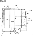
- the vehicle door structure according to this embodiment is provided, as illustrated in Fig. 11 , with a sliding opening/closing type first door panel 60 and a swing opening/closing type second door panel 61.
- an intermediate slide rail 62 as a second slide rail and a lower slide rail 64 as a third slide rail are provided in the second door panel 61.
- the intermediate slide rail 62 has substantially the same configuration as that of the intermediate slide rail 40 in the first embodiment and has a rail upper face portion, a rail lower face portion, a rail side face portion, and a rail outer edge portion, though not shown.
- the second guide body 63 guided by the intermediate slide rail 62 has the same configuration as that of the second guide body 30 of the first embodiment and is provided at the distal end of an intermediate arm (not shown) provided in the second door panel 61.
- the second guide body 63 is provided with a radial roller (not shown) and a thrust roller (not shown) rolling in the intermediate slide rail.
- the lower slide rail 64 has the same configuration as that of the intermediate slide rail 62, and the third guide body 65 guided by the lower slide rail 64 has the same configuration as that of the second guide body 63. Therefore, the first door panel 60 is connected to the vehicle body 11 through the first guide body 26 and also connected to the second door panel 61 through the second guide body 63 and the third guide body 65.
- the first guide body 26 In the state in which the first door panel 60 begins to be opened, the first guide body 26 is located in the front of the center of gravity G of the first door panel 60, and the second guide body 63 and the third guide body 65 are located in the rear of the center of gravity G.
- the moment generated by the weight of the first door panel 60 can be successfully received by the vehicle body 11 and the second door panel 61.
- the first door panel 60 can be fully opened by sliding movement, and the second door panel 61 can be opened and closed when the first door panel 60 is fully open.
- the first guide body 26 of the first door panel 60 is guided along the upper slide rail 23 provided in the vehicle body 11.
- the second guide body 63 is guided by the intermediate slide rail 62 provided in the second door panel 61, and the third guide body 65 is guided by the lower slide rail 64 provided in the second door panel 61.
- the upper part of the first door panel 60 is supported by the vehicle body 11, and the intermediate part and the lower part of the first door panel 60 are supported by the second door panel 61, and thus, stability of the first door panel 60 with respect to the second door panel 61 during opening and closing of the first door panel 60 is improved. Also, since there is no need to provide a lower slide rail in the vehicle body 11, a space for installing the lower slide rail in the vehicle body 11 can be saved, and a floor in the vehicle interior can be lowered.
- the first guide body 26 is in the state not removed from the upper slide rail 23 (however, in a removable state).
- the first door panel 70 is in the fully open state and the second door panel 71 is in the fully closed state, a first guide body 73 guided by an upper slide rail 72 as the first slide rail is in a fully removed state from the upper slide rail 72.
- the members common to those in the first embodiment are given the same reference numerals as those in the first embodiment, and the description will be omitted.
- the vehicle door structure according to this embodiment is provided, as illustrated in Fig. 12 , with the sliding opening/closing type first door panel 70 and the swing opening/closing type second door panel 71.
- the upper slide rail 72 as the first slide rail is provided on a roof side rail ceiling portion of the vehicle body 11 along the upper part of the first door panel 70 in the fully closed state.
- the upper slide rail 72 guides the first guide body 73 provided at the distal end of an upper arm 75 of the first door panel 70 and restricts the movement of the first guide body 73 in the up-down direction and the left-right direction.
- the upper slide rail 72 is provided with a rail upper face portion, a rail lower face portion, a rail side face portion, and a rail outer edge portion similarly to the upper slide rail 23 in the first embodiment, and the shape of a cross-section is a channel shape.
- the longitudinal direction of the upper slide rail 72 matches the front-rear direction of the vehicle body 11, the front end of the upper slide rail 72 is located in the vicinity of the pillar 19, and the rear end of the upper slide rail 72 is located in the vicinity of the front edge end of the second door panel 71.
- a second door side slide rail 74 is fixed to the second door panel 71.
- the second door side slide rail 74 guides the first guide body 73 having been removed from the rear end of the upper slide rail 72 and also restricts the movement of the first guide body 73 in the up-down direction and in the left-right direction of the vehicle body 11 with respect to the second door panel 71.
- the second door side slide rail 74 corresponds to a connection lock mechanism which restricts separation of the first door panel 70 from the second door panel 71 in a direction at a right angle to the sliding direction when the first door panel 70 is fully open.
- the slide restricting mechanism which restricts the sliding movement of the first guide body 73 in the second door side slide rail 74 in the front-rear direction of the vehicle body 11, is provided.
- the slide restricting mechanism is provided with a lock plate portion 76 provided in the upper arm 75 and a lock pin 77 provided in the second door side slide rail 74.
- the first guide body 73 is removed from the upper slide rail 72 and transfers to the second door side slide rail 74, and the sliding movement of the first guide body 73 is restricted by the slide restricting mechanism. While the first guide body 73 is restricted by the slide restricting mechanism, the second door panel 71 can be opened.
- the present invention is not limited by the above embodiments but is capable of various changes as follows within a range of the gist of the present invention.
- the vehicle door structure of the present invention is applied to a vehicle door structure that opens/closes the rear door opening formed on the side portion of the vehicle body, but an application position of the vehicle door structure of the present invention to the vehicle body is not particularly limited.
- the present invention may be applied to a door structure that opens/closes a rear side opening formed on the rear face of the vehicle body.
- the weight of the first door panel can be supported by the radial rollers provided in the first to third guide bodies, but in the first embodiment, for example, the radial rollers 32 and 37 are provided only in the second guide body 30 and the third guide body 34 so that the weight of the first door panel 20 is distributed and supported by the radial rollers 32 and 37.
- the radial rollers 32 and 37 may be provided only on the first guide body 26 and the second guide body 30 so that the weight of the first door panel 20 is supported by the radial rollers 32 and 37.
- the radial rollers 28 and 32 may be provided only on the first guide body 26 and the second guide body 63 so that the weight of the first door panel 60 is distributed and supported by the radial rollers 28 and 32. Also, in the second embodiment, radial rollers guided by the slide rails provided at least in the vehicle body 11 are preferably provided on both sides of the center of gravity G of the first door panel 60 in the sliding direction of the first door panel 60 so that the weight of the first door panel 60 is supported by the radial rollers.
- the second door side slide rail 74 is provided in the rear of the rear end of the upper slide rail 72, but if the lower slide rail 42 is provided on the lower part of the vehicle body 11, the second door side slide rail similar to the second door side slide rail 72 is preferably provided in the rear of the rear end of the lower slide rail 42.
- each upper and lower guide body of the first door panel 70 is held by the corresponding second door side slide rails, and the first door panel 70 is further stably held with respect to the second door panel 71.
- slide rails including the upper slide rail, the intermediate slide rail, and the lower slide rail and three guide bodies guided by each of the slide rails are provided.
- the slide rails may be used only as the first slide rail provided in the vehicle body 11 and the second slide rail provided in the second door panel.
- the first slide rail is extended to the upper part of the second door panel and the first guide body moving along the first slide rail is provided at the front edge end and the rear edge end of the first door panel, respectively, so that the first door panel is supported by the two first guide bodies and the one second guide body moving along the second slide rail.
- first and second slide rail are preferably provided for the first and second slide rail, respectively, so that the first door panel is supported by these guide bodies, and the sliding of the first door panel is stabilized.
- a cutout rail part is provided corresponding to each of the position of a plurality of the first guide bodies in the case in which the first door panel is brought into the fully open state.
- the second slide rail is preferably provided at the position opposite to the first slide rail in the second door panel with respect to the center of gravity G of the first door panel.
- cars to which the vehicle door structure is applied are not specifically specified, but vehicles to which the present invention is applied may be passenger automobiles having three rows of seats, or cargo vehicles having a luggage compartment for cargo transportation.
- a passenger can board and alight without moving the seats of the last row by fully opening the first and second door panels.
- cargo vehicles even a large piece of luggage, which previously required that a back door be opened and closed for loading and unloading, can be loaded and unloaded without opening and closing the back door.
Description
- The present invention relates to a vehicle door structure, and particularly to a vehicle door structure having a composite door in which a sliding door and a swing door are combined.
- As a prior-art vehicle door structure, a vehicle door system disclosed in
Patent Document 1 is known, for example. The vehicle door system inPatent Document 1 has a first door panel and a second door panel, and the first door panel and the second door panel collaborate with each other and close a door opening in a vehicle body. The first door panel is relatively moved with respect to the second door panel and opens/closes a part of the door opening. Also, in this vehicle door system, the first door panel and the second door panel are relatively moved with respect to the vehicle body to open and close the whole of the door opening. - The first door panel slides in the horizontal direction along a pair of slide tracks provided on an upper part and a lower part of the second door panel. The second door panel is connected to the vehicle body through a hinge assembly, and the second door panel is rotatable around a vertical axis with respect to the vehicle body by using the hinge assembly as a fulcrum.
-
Patent Document 2 discloses a vehicular opening system according to the preamble ofclaim 1, which consists of at least a primary and secondary door, mounted to move, relative to a frame, between two extreme positions of open and closed. The primary door is mounted to pivot on the base and the secondary door is mounted to slide, relative to the primary door, between a closed position, when it is applied against the frame and extends the line of the primary door, and an open position, where it is located alongside the primary door. -
- Patent Document 1:
JP 2006-240611 A - Patent Document 2:
FR 2 818 591 A - In the vehicle door system in
Patent Document 1, the first door panel is supported by the slide tracks provided on the second door panel and slides between the fully open position where the first door panel substantially overlap the second door panel and a fully closed position extended in the horizontal direction from the second door panel along the slide tracks. While the first door panel in the fully closed position begins to be moved toward the fully open position, the first door panel is supported by the slide tracks at a portion on one end side in the sliding direction, that is, at a portion far from the center of gravity of the first door panel in the sliding direction. Thus, in the first door panel, a moment around the horizontal axis is generated by the weight of the first door panel. Also, while the first door panel in the fully closed position begins to be moved toward the fully open position, if an external force is applied to the first door panel from the vehicle interior to the outside of the vehicle body, a moment around the vertical axis occurs in the first door panel. In order to reliably receive these moments by the slide tracks or the second door panel, rigidity of the slide tracks or the second door panel should be improved. However, if the slide tracks and the second door panel are reinforced in order to improve the rigidity thereof, the weights of the first door panel and the second door panel are increased, and opening/closing of these door panels become difficult. - An objective of the present invention is to provide a vehicle door structure in which a part of or the whole of the door opening can be opened/closed by a sliding type first door panel and a swing type second door panel and has rigidity higher than the prior-art doors.
- To achieve the foregoing, a vehicle door structure according to
claim 1 is provided. -
-
Fig. 1 is a side view of a vehicle provided with a vehicle door structure according to a first embodiment of the present invention; -
Fig. 2 is a diagram as viewed in the direction of arrow 2-2 inFig. 1 ; -
Fig. 3(a) is a cross-sectional view taken alongline 3a-3a inFig. 2 ; -
Fig. 3(b) is a cross-sectional view taken alongline 3b-3b inFig. 2 ; -
Fig. 4 is a diagram as viewed in the direction of arrow 4-4 inFig. 1 ; -
Fig. 5 is a cross-sectional view taken along line 5-5 inFig. 4 ; -
Fig. 6 is a cross-sectional view taken along line 6-6 inFig. 1 ; -
Fig. 7(a) is a cross-sectional view taken alongline 7a-7a inFig. 6 ; -
Fig. 7(b) is a cross-sectional view taken alongline 7b-7b inFig. 7 ; -
Fig. 8 is an enlarged view illustrating a slide restricting mechanism in the vehicle door structure inFig. 1 ; -
Fig. 9(a) is a side view of a vehicle illustrating the first door panel in a state in which the door begins to be opened -
Fig. 9(b) is a side view of the vehicle illustrating the first door panel in the fully open state; -
Fig. 10 is a perspective view of the vehicle illustrating a second door panel in the fully open state; -
Fig. 11 is a side view of a vehicle provided with a vehicle door structure according to a second embodiment of the present invention; and -
Fig. 12 is a perspective view illustrating an essential part of a vehicle door structure not forming part of the invention. - A vehicle door structure according to a first embodiment of the present invention will be described below by referring to the attached drawings. The vehicle door structure of this embodiment is applied to a side part of a
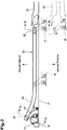
vehicle body 11. InFig. 1 , the left side corresponds to the front of the vehicle and the right side corresponds to the rear of the vehicle. As illustrated inFig. 1 , a front door opening 12 located on the side of the front seats and a rear door opening 13 located on the rear of the front seats are formed on the side face of thevehicle body 11. - The
front door opening 12 is opened and closed by afront door panel 14. Thefront door panel 14 is connected to thevehicle body 11 by a pair of upper andlower hinge mechanisms 15. Thehinge mechanisms 15 are provided with a fulcrum shaft (not shown) extending vertically. Thefront door panel 14 swings around the fulcrum shaft as the center and opens/closes the front door opening 12. A frontdoor lock mechanism 16 is provided between thefront door panel 14 and thevehicle body 11. The frontdoor lock mechanism 16 connects thefront door panel 14 to thevehicle body 11 and fully closes the front door opening 12. The frontdoor lock mechanism 16 is provided with a latch (not shown) and a door lock striker (not shown) and keeps thefront door panel 14 in the fully closed state by means of connection between the latch and the door lock striker. Thefront door panel 14, which fully closes the front door opening 12, can be opened from outside the vehicle by operating anouter handle 17 provided on the outer face of thefront door panel 14. Also, thefront door panel 14 in the fully closed state can be opened from inside the vehicle by operating aninner handle 18 provided on the inner face (face exposed into the vehicle interior) of thefront door panel 14. - The
rear door opening 13 is formed on the side of a luggage compartment provided in the rear of the front seats. Therear door opening 13 is opened and closed by a vehicle door mechanism provided with a slide opening/closing typefirst door panel 21 and a swing opening/closing typesecond door panel 22. In the rear door opening 13, a region closed by thefirst door panel 21 is referred to as a first dooropening region 13A, and a region closed by thesecond door panel 22 is referred to as a second dooropening region 13B. Thefirst door panel 21 and thesecond door panel 22 collaborate with each other to open/close the whole rear door opening 13. Thefirst door panel 21 slides in the front-rear direction of thevehicle body 11 and opens/closes the first dooropening region 13A. Thefirst door panel 21 is located outside thesecond door panel 22 in the fully open state and overlaps thesecond door panel 22. Thefirst door panel 21 moves in the front-rear direction of thevehicle body 11 with respect to thevehicle body 11 and thesecond door panel 22 through the slide mechanism. - The slide mechanism is provided with an
upper slide rail 23 as a first slide rail, anintermediate slide rail 40 as a second slide rail, and alower slide rail 42 as a third slide rail. Also, the slide mechanism is provided with afirst guide body 26 guided by theupper slide rail 23, asecond guide body 30 guided by theintermediate slide rail 40, and athird guide body 34 guided by thelower slide rail 42. As illustrated inFig. 2 , anupper arm 27 extends from a position close to the front edge on the upper part of thefirst door panel 21 toward thevehicle body 11, and thefirst guide body 26 is provided at the distal end of thisupper arm 27. As illustrated inFigs. 3(a) and 3(b) , thefirst guide body 26 is provided with aradial roller 28 and athrust roller 29, and therollers upper slide rail 23. The rotational axis of theradial roller 28 extends horizontally, and the rotational axis of thethrust roller 29 extends vertically. - The
upper slide rail 23 is provided on a roof side rail ceiling portion of thevehicle body 11 located above the firstdoor opening region 13A and extends along the upper part of thefirst door panel 21 in the fully closed state. Theupper slide rail 23 is a rail that guides thefirst guide body 26 provided in thefirst door panel 21 and restricts movement of thefirst guide body 26 in the up-down direction and the left-right direction of thevehicle body 11. As illustrated inFig. 3(a) , theupper slide rail 23 is provided with a railupper face portion 23A, a raillower face portion 23B, a railside face portion 23C, and a railouter edge portion 23D, and the shape of a cross-section is a channel shape. Theradial roller 28 rolls on the raillower face portion 23B in accordance with the movement of thefirst door panel 21. The railside face portion 23C and the railouter edge portion 23D restrict the movement of thethrust roller 29 in the left-right direction of thevehicle body 11. - As illustrated in
Fig. 2 , the longitudinal direction of theupper slide rail 23 matches the front-rear direction of thevehicle body 11. The front end of theupper slide rail 23 is located in the vicinity of apillar 19 located between thefront door panel 14 and thefirst door panel 21. The rear end of theupper slide rail 23 is located in the vicinity of the front edge of thesecond door panel 22. Theupper slide rail 23 is provided with acurved rail portion 24 in a predetermined range close to the front end. When thefirst door panel 21 in the state overlapped with thesecond door panel 22 is made to slide to the front of thevehicle body 11, thefirst guide body 26 is guided by thecurved rail portion 24, and thus thefirst door panel 21 is moved to a position where the outer face thereof becomes flush with the outer face of thesecond door panel 22 and closes the firstdoor opening region 13A. As illustrated inFig. 3(b) , in the rear end of theupper slide rail 23, acutout rail portion 25 not having a railouter edge portion 23D is formed. While thefirst guide body 26 is located in thecutout rail portion 25, thefirst guide body 26 can be removed from theupper slide rail 23 and scan be separated from thevehicle body 11. - As illustrated in
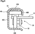
Figs. 1 and4 , anintermediate arm 31 extending toward thevehicle body 11 is provided in an intermediate portion in the up-down direction of thefirst door panel 21 and close to the rear edge of thefirst door panel 21. Thesecond guide body 30 is provided at the distal end of thisintermediate arm 31. As illustrated inFig. 5 , thesecond guide body 30 is provided with aradial roller 32 and a pair of front andrear thrust rollers 33, and therollers intermediate slide rail 40. InFig. 5 , only thethrust roller 33 located in the front in the pair ofthrust rollers 33 is illustrated. The rotational axis of theradial roller 32 extends horizontally, and the rotational axis of thethrust rollers 33 extends vertically. Theintermediate arm 31 is provided rotatably in the left-right direction with respect to thefirst door panel 21 with arotary shaft 31A as a fulcrum. - The
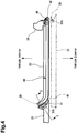
intermediate slide rail 40 is provided in an intermediate portion in the up-down direction on the outer face of thesecond door panel 22, and the longitudinal direction of theintermediate slide rail 40 matches the front-rear direction of thevehicle body 11. As illustrated inFig. 4 , the front end of theintermediate slide rail 40 is located at the front edge of thesecond door panel 22, and the rear end of theintermediate slide rail 40 is located at the rear edge of thesecond door panel 22. That is, theintermediate slide rail 40 is provided to cross the outer face of thesecond door panel 22 in the front-rear direction. - The
intermediate slide rail 40 is a rail that guides thesecond guide body 30 provided in thefirst door panel 21 and restricts the movement of thesecond guide body 30 in the up-down direction and the left-right direction of thevehicle body 11. As illustrated inFig. 5 , theintermediate slide rail 40 is provided with a railupper face portion 40A, a raillower face portion 40B, a railside face portion 40C, and a railouter edge portion 40D similarly to theupper slide rail 23, and the shape of the cross-section is a channel shape. Theintermediate slide rail 40 is provided with acurved rail portion 41 in a predetermined range close to the front end thereof. When thefirst door panel 21 in the state overlapped with thesecond door panel 22 is made to slide to the front of thevehicle body 11, thesecond guide body 30 is guided along thecurved rail portion 41, and thefirst door panel 21 is moved to a position where the outer face thereof becomes flush with the outer face of thesecond door panel 22 and closes the firstdoor opening region 13A. The curvature of thecurved rail portion 41 of theintermediate slide rail 40 is set larger than the curvature of thecurved rail portion 24 of theupper slide rail 23. Thesecond guide body 30 is smoothly moved in theintermediate slide rail 40 including thecurved rail portion 41 by means of rotation of theintermediate arm 31 with respect to thesecond door panel 22. - As illustrated in
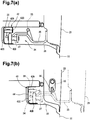
Figs. 1 and6 , alower arm 35 extends from a portion close to the front edge of the lower part of thefirst door panel 21 toward thevehicle body 11 across astep 36, and thethird guide body 34 is provided at the distal end of thelower arm 35. As illustrated inFigs. 7(a) and 7(b) , thethird guide body 34 is provided with aradial roller 37 and athrust roller 38, and therollers lower slide rail 42. The rotational axis of theradial roller 37 extends horizontally, and the rotational axis of thethrust roller 38 extends vertically. - As illustrated in
Fig. 6 , thelower slide rail 42 is provided at a position close to the floor of thevehicle body 11 on the lower side of the firstdoor opening region 13A to follow the lower part of thefirst door panel 21 in the fully closed state. Thelower slide rail 42 is a rail that guides thethird guide body 34 of thefirst door panel 21 and restricts the movement of thethird guide body 34 in the up-down direction and the left-right direction of thevehicle body 11. As illustrated inFigs. 7(a) and 7(b) , thelower slide rail 42 is provided with a railupper face portion 42A, a raillower face portion 42B, a railside face portion 42C, and a railouter edge portion 42D similarly to theupper slide rail 23. Theradial roller 37 rolls on the raillower face portion 42B in accordance with the movement of thefirst door panel 21. The railside face portion 42C and the railouter edge portion 42D restrict the movement of thethrust roller 38 in the left-right direction of thevehicle body 11. - The longitudinal direction of the
lower slide rail 42 matches the front-rear direction of thevehicle body 11, and the front end of thelower slide rail 42 is located in the vicinity of thepillar 19 located between thefront door panel 14 and thefirst door panel 21, and the rear end of thelower slide rail 42 is located in the vicinity of the front edge of thesecond door panel 22. Thelower slide rail 42 is provided with acurved rail portion 43 in a predetermined range close to the front end thereof. When thefirst door panel 21 in the state overlapped with thesecond door panel 22 is made to slide to the front of thevehicle body 11, thethird guide body 34 is guided by thecurved rail portion 43, and thefirst door panel 21 is moved to a position where the outer face thereof becomes flush with the outer face of thesecond door panel 22 and closes the firstdoor opening region 13A. At the rear end of thelower slide rail 42, acutout rail portion 44 not having the railouter edge portion 42D is formed. Thethird guide body 34 can be removed from thelower slide rail 42 and separated from thevehicle body 11 while thethird guide body 34 is located in thecutout rail portion 44. - As illustrated in
Figs. 1 and4 , thesecond door panel 22 is connected to thevehicle body 11 by a pair ofhinge mechanisms 45. In this embodiment, thehinge mechanisms 45 are provided at a portion corresponding to theintermediate slide rail 40 of thesecond door panel 22 and a portion corresponding to the lower part of thesecond door panel 22 in arear pillar 39. Thesecond door panel 22 is rotatable with respect to thevehicle body 11 through thehinge mechanisms 45 in a state in which thefirst door panel 21 is fully open and overlapped with thesecond door panel 22. As illustrated inFig. 4 , thehinge mechanism 45 is provided with afulcrum shaft 46 extending vertically, and thesecond door panel 22 is axially rotated with thefulcrum shaft 46 as a fulcrum and opens/closes therear door opening 13. - A second door opening/
closing restricting mechanism 50 is provided between thesecond door panel 22 and thevehicle body 11. In this embodiment, as illustrated inFig. 1 , the second door opening/closing restricting mechanism 50 is provided at positions corresponding to the upper part and the lower part of thesecond door panel 22, respectively. The second door opening/closing restricting mechanisms 50 connects thesecond door panel 22 to thevehicle body 11 and fully closes the seconddoor opening region 13B. The second door opening/closing restricting mechanism 50 is provided with a latch (not shown) provided in thesecond door panel 22 and a door lock striker (not shown) provided in thevehicle body 11 and keeps thesecond door panel 22 in the fully closed state by means of connection between the latch and the door lock striker. An opening/closinghandle 47 is provided at the front edge portion of thesecond door panel 22. The connection between thesecond door panel 22 and thevehicle body 11 held by the second door opening/closing restricting mechanisms 50 is cancelled by means of an operation of the opening/closinghandle 47, whereby thesecond door panel 22 can be opened/closed. The opening/closinghandle 47 can cancel the connection by means of the second door opening/closing restricting mechanism 50 only when thefirst door panel 21 is in the fully open state overlapping with thesecond door panel 22 and also if thesecond door panel 22 is in the fully closed state. That is, if thefirst door panel 21 is in a state other than fully open, the connection between thesecond door panel 22 and thevehicle body 11 is not cancelled by the second door opening/closing restricting mechanisms 50 even if the opening/closinghandle 47 is operated. - As illustrated in
Fig. 1 , a first door opening/closing restricting mechanism 51 is provided between thefirst door panel 21 and thesecond door panel 22. The first door opening/closing restricting mechanism 51 connects thefirst door panel 21 in the fully closed state to thesecond door panel 22. The first door opening/closing restricting mechanism 51 is provided with a latch (not shown) provided at the rear edge of thefirst door panel 21 and a door lock striker (not shown) provided at the front edge of the second door panel. If thefirst door panel 21 is in the fully closed state, the sliding movement of thefirst door panel 21 with respect to thevehicle body 11 and thesecond door panel 22 is restricted by means of connection between the latch and the door lock striker of the first door opening/closing restricting mechanism 51 to each other. Anouter handle 48 is provided on the outer face of thefirst door panel 21, and aninner handle 49 is provided on the inner face of thefirst door panel 21. The connection between thefirst door panel 21 and thesecond door panel 22 by the first door opening/closing restricting mechanism 51 can be cancelled by means of operations of theouter handle 48 and theinner handle 49. - A
slide restricting mechanism 52 is provided between thefirst door panel 21 and thesecond door panel 22. Theslide restricting mechanism 52 connects thefirst door panel 21 in the fully open state overlapping thesecond door panel 22 to thesecond door panel 22. As illustrated inFig. 8 , theslide restricting mechanism 52 is provided with alatch 53 provided in thefirst door panel 21 and adoor lock striker 54 provided in thesecond door panel 22. If thefirst door panel 21 is in the fully open state, by means of connection between thelatch 53 and thedoor lock striker 54 to each other, the sliding movement of thefirst door panel 21 with respect to thesecond door panel 22 is restricted. In this embodiment, as illustrated inFig. 1 , a pair of upper and lowerslide restricting mechanisms 52 is provided. Theslide restricting mechanisms 52 have a function of restricting the movement of thefirst door panel 21 in the up-down direction and the left-right direction with respect to thesecond door panel 22. Also, theslide restricting mechanisms 52 have a function corresponding to a connecting lock mechanism that connects thefirst door panel 21 and thesecond door panel 22 to each other. The cancellation of the connection between thefirst door panel 21 and thesecond door panel 22 by theslide restricting mechanisms 52 is configured to be able to be realized by operations of theouter handle 48 and theinner handle 49 provided in thefirst door panel 21 only when the second door opening/closing restricting mechanisms 50 are not cancelled. If thesecond door panel 22 is in the open state, the connection between thefirst door panel 21 and thesecond door panel 22 by theslide restricting mechanism 52 is configured not to be cancelled. - As illustrated in
Figs. 6 and7(a) , apositioning pin 55 is provided in thelower arm 35. The distal end of thepositioning pin 55 is directed rearward of the vehicle. Also, as illustrated inFig. 7(b) , apin receiving hole 56 through which thepositioning pin 55 can be inserted is provided at the front edge of thesecond door panel 22. If thefirst door panel 21 is slid with respect to thesecond door panel 22 so that thefirst door panel 21 becomes fully open, thepositioning pin 55 is inserted through thepin receiving hole 56. As a result, thefirst door panel 21 is positioned with respect to thesecond door panel 22 in the up-down direction and the left-right direction of thevehicle body 11, and also, the movement of thefirst door panel 21 is restricted in the up-down direction and the left-right direction of thevehicle body 11. Therefore, thepositioning pin 55 and thepin receiving hole 56 correspond to the connecting lock mechanism, which prevents thefirst door panel 21 from separating from thesecond door panel 22 in a direction (right and left direction of the vehicle body 11) at a right angle with the sliding direction thereof. - Subsequently, an operation of the vehicle door structure of this embodiment will be described. First, a case in which the
first door panel 21 is to be fully opened from the state in which thefirst door panel 21 and thesecond door panel 22 are both fully closed, that is, the rear door opening 13 is covered by thefirst door panel 21 and thesecond door panel 22 will be described. If thefirst door panel 21 illustrated inFig. 1 is in the fully closed state, thefirst door panel 21 is supported by thevehicle body 11 and thesecond door panel 22. Also, the first door opening/closing restricting mechanism 51 restricts the sliding movement of thefirst door panel 21 with respect to thesecond door panel 22. Moreover, the second door opening/closing restricting mechanism 50 restricts the opening/closing of thesecond door panel 22 with respect to thevehicle body 11. In this embodiment, the center of gravity G of thefirst door panel 21 is located at substantially the center of thefirst door panel 21. - The connection by the first door opening/
closing restricting mechanism 51 is cancelled by means of the operation of theouter handle 48 or theinner handle 49, and thefirst door panel 21 is slid rearward of thevehicle body 11 with respect to thesecond door panel 22. Thefirst guide body 26 is guided along theupper slide rail 23, thesecond guide body 30 is guided along theintermediate slide rail 40, and thethird guide body 34 is guided along thelower slide rail 42. When thefirst door panel 21 begins to be opened, each of theguide bodies curved rail portions first door panel 21 is slid rearward while going outward of thevehicle body 11. When thefirst door panel 21 is moved from the fully closed state to the state of beginning to be opened illustrated inFig. 9(a) , the vicinity of the front edge of thefirst door panel 21 is connected to thevehicle body 11 through thefirst guide body 26 and thethird guide body 34, and the vicinity of the rear edge of thefirst door panel 21 is connected to thesecond door panel 22 through thesecond guide body 30. - Also, in this state, the
first guide body 26, which is guided by theupper slide rail 23, and thesecond guide body 30, which is guided by theintermediate slide rail 40, are located on both sides of the center of gravity G of thefirst door panel 21 in the sliding direction. Since thefirst guide body 26 and thethird guide body 34 are located in front of the center of gravity G of thefirst door panel 21 and thesecond guide body 30 is located to the rear of the center of gravity G, the moment generated by the weight of thefirst door panel 21 can be successfully received by the slide rails 23, 40, and 42. - Also, the
first guide body 26 and thethird guide body 34 are located in the vicinity of the front edge of thefirst door panel 21, and thesecond guide body 30 is located in the vicinity of the rear edge end of thefirst door panel 21. Thus, even if an external force from inside the vehicle interior to the outside of the vehicle body 11 (in a direction at a right angle to the sliding direction of the first door panel 21) acts on thefirst door panel 21 in the state of beginning to be opened, for example, the moment by this external force can be favorably received through theguide bodies first door panel 21, respectively. - By sliding the
first door panel 21 in the state of beginning to be opened to the rear of thevehicle body 11 with respect to thesecond door panel 22, the firstdoor opening region 13A is enlarged while thefirst door panel 21 is overlapped with thesecond door panel 22. As illustrated inFig. 9(b) , if the rearward sliding movement of thefirst door panel 21 is completely finished, the firstdoor opening region 13A is maximized, and thefirst door panel 21 is in the fully open state. When thefirst door panel 21 is fully open, thelatch 53 provided in thefirst door panel 21 is connected to thedoor lock striker 54, which is provided in thesecond door panel 22. The connection between thelatch 53 and thedoor lock striker 54, which constitute theslide restricting mechanism 52, restricts the sliding movement of thefirst door panel 21 with respect to thesecond door panel 22. - Also, when the rearward sliding movement of the
first door panel 21 is completely finished, thepositioning pin 55 provided in thelower arm 35 is inserted through thepin receiving hole 56, and thefirst door panel 21 is positioned in the left-right direction with respect to thesecond door panel 22, and the movement in the left-right direction of thefirst door panel 21 is restricted. - When the rearward sliding movement of the
first door panel 21 is completely finished, thefirst guide body 26 becomes removable from theupper slide rail 23, though it has not been removed yet. Thefirst guide body 26 is guided by theupper slide rail 23 until thefirst door panel 21 is brought into the fully open state. The railside face portion 23C and the railouter edge portion 23D of theupper slide rail 23 restrict the movement of theradial roller 28 in thefirst guide body 26 in the left-right direction of thevehicle body 11. Thus, thefirst guide body 26 is not removed from theupper slide rail 23 until thefirst door panel 21 is brought into the fully open state. On the other hand, when the rearward sliding movement of thefirst door panel 21 is completely finished, thefirst guide body 26 is located in thecutout rail portion 25 not having the railouter edge portion 23D, and thus, thefirst guide body 26 is removable from theupper slide rail 23. Also, since thecutout rail portion 44 is formed in thelower slide rail 42 similarly to theupper slide rail 23, when the rearward sliding movement of thefirst door panel 21 is completely finished, thethird guide body 34 becomes removable from thelower slide rail 42. - Since the
intermediate slide rail 40 is not provided with the cutout rail portion, even if thefirst door panel 21 is in the fully open state, thesecond guide body 30 cannot be removed from theintermediate slide rail 40, and the railouter edge portion 40D of theintermediate slide rail 40 prevents removal of thesecond guide body 30. As described above, while thefirst door panel 21 is fully open, the connection of thefirst guide body 26 and thethird guide body 34 to thevehicle body 11 is cancelled, and the connection between thefirst door panel 21 and thesecond door panel 22 is maintained. That is, the connection between thefirst door panel 21 and thesecond door panel 22 is maintained by the connection between thesecond guide body 30 and theintermediate slide rail 40 and theslide restricting mechanism 52. The connection between thefirst door panel 21 and thesecond door panel 22 by theslide restricting mechanism 52 is cancelled by operating theouter handle 48 or theinner handle 49 from this state, and thefirst door panel 21 can be made to slide to the front of thevehicle body 11 with respect to thesecond door panel 22. - If the
first door panel 21 is fully open and thesecond door panel 22 is fully closed, the connection between thevehicle body 11 and thesecond door panel 22 by the second door opening/closing restricting mechanism 50 can be cancelled by operating the opening/closinghandle 47. By canceling the connection by the second door opening/closing restricting mechanism 50, thesecond door panel 22 can be opened with respect to thevehicle body 11 by axial rotation using thefulcrum shaft 46 as a fulcrum through thehinge mechanism 45. In the opening/closing of thesecond door panel 22 through thehinge mechanism 45, thefirst door panel 21 follows the opening/closing of thesecond door panel 22 in a state in which thefirst door panel 21 is overlapped with thesecond door panel 22. As illustrated inFig. 10 , thesecond door panel 22 can be opened substantially at a right angle with respect to the front-rear direction of thevehicle body 11, and if thesecond door panel 22 is opened substantially at a right angle, the seconddoor opening region 13B is fully opened, and the rear door opening 13 is brought into the fully open state. - If the
second door panel 22 in the fully open state is closed and the second door opening/closing restricting mechanism 50 restricts opening/closing of thesecond door panel 22 with respect to thevehicle body 11, the connection between thefirst door panel 21 and thesecond door panel 22 by theslide restricting mechanism 52 can be cancelled by means of operation of theouter handle 48. After the connection by theslide restricting mechanism 52 is cancelled, the fully closed state in which thefirst door panel 21 closes the firstdoor opening region 13A is brought about by sliding thefirst door panel 21 forward. - This embodiment has the following advantages.
- (1) The
first guide body 26 guided by theupper slide rail 23 and thesecond guide body 30 guided by theintermediate slide rail 40 are located on both sides of the center of gravity G of thefirst door panel 21 in the sliding direction of thefirst door panel 21 and moreover, thethird guide body 34 supports thefirst door panel 21. Thus, the moment generated in thefirst door panel 21 can be received not only by thesecond door panel 22 but also by thevehicle body 11. Thus, there is no need to reinforce theintermediate slide rail 40 and thesecond door panel 22 in order to reliably receive the moment but as a result, a weight increase of theintermediate slide rail 40 and thesecond door panel 2 caused by such reinforcement can be prevented. When thefirst door panel 21 is in the fully open state, thefirst guide body 26 is in the removed state or removable state from theupper slide rail 23, and thus, thesecond door panel 22 is capable of axial rotation through thehinge mechanism 45 together with thefirst door panel 21. Also, even if thefirst door panel 21 is in the state of beginning to be opened, the moment caused by the weight of thefirst door panel 21 can be successfully received by thesecond door panel 22 and thevehicle body 11. Also, even if a moment generated by the external force from the vehicle interior to the outside of thevehicle body 11 acts on thefirst door panel 21, the moment can be successfully received by thesecond door panel 22 and thevehicle body 11. - (2) When the
first door panel 21 is in the fully open state, thefirst door panel 21 and thesecond door panel 22 are connected to each other by theslide restricting mechanism 52. As a result, even if thefirst guide body 26 is brought into the removed state or removable state from theupper slide rail 23, thefirst door panel 21 is prevented from separating from thesecond door panel 22 in a direction at a right angle to the sliding direction thereof. - (3) When the
first door panel 21 is fully open, thepositioning pin 55 is inserted through thepin receiving hole 56. As a result, even if thefirst guide body 26 is brought into the removed state or removable state from theupper slide rail 23, thefirst door panel 21 is prevented from separating from thesecond door panel 22 in a direction at a right angle to the sliding direction thereof. - (4) Since the
slide restricting mechanism 52, which restricts the sliding movement of thefirst door panel 21 with respect to thesecond door panel 22, is provided, the sliding movement of thefirst door panel 21 with respect to thesecond door panel 22 can be prevented during opening/closing of thesecond door panel 22. - (5) The
first guide body 26 of thefirst door panel 21 is guided by theupper slide rail 23 provided in thevehicle body 11, thethird guide body 34 is guided by thelower slide rail 42 provided in thevehicle body 11, and thesecond guide body 30 is guided by theintermediate slide rail 40 provided in thesecond door panel 22. Therefore, since the upper and lower portions of thefirst door panel 21 are supported by thevehicle body 11 through the first andthird guide bodies first door panel 21 with respect to thevehicle body 11 is improved during opening/closing of thefirst door panel 21. - Subsequently, a vehicle door structure according to a second embodiment of the present invention will be described.
- This embodiment is different from the first embodiment in a point that the
lower slide rail 42 as the third slide rail of the slide mechanism is formed in thesecond door panel 22. In this embodiment, the members common with those in the first embodiment are given the same reference numerals as those in the first embodiment, and the description thereof will be omitted. - The vehicle door structure according to this embodiment is provided, as illustrated in
Fig. 11 , with a sliding opening/closing typefirst door panel 60 and a swing opening/closing typesecond door panel 61. In the vehicle door structure of this embodiment, anintermediate slide rail 62 as a second slide rail and alower slide rail 64 as a third slide rail are provided in thesecond door panel 61. Theintermediate slide rail 62 has substantially the same configuration as that of theintermediate slide rail 40 in the first embodiment and has a rail upper face portion, a rail lower face portion, a rail side face portion, and a rail outer edge portion, though not shown. Thesecond guide body 63 guided by theintermediate slide rail 62 has the same configuration as that of thesecond guide body 30 of the first embodiment and is provided at the distal end of an intermediate arm (not shown) provided in thesecond door panel 61. Thesecond guide body 63 is provided with a radial roller (not shown) and a thrust roller (not shown) rolling in the intermediate slide rail. - The
lower slide rail 64 has the same configuration as that of theintermediate slide rail 62, and thethird guide body 65 guided by thelower slide rail 64 has the same configuration as that of thesecond guide body 63. Therefore, thefirst door panel 60 is connected to thevehicle body 11 through thefirst guide body 26 and also connected to thesecond door panel 61 through thesecond guide body 63 and thethird guide body 65. - In the state in which the
first door panel 60 begins to be opened, thefirst guide body 26 is located in the front of the center of gravity G of thefirst door panel 60, and thesecond guide body 63 and thethird guide body 65 are located in the rear of the center of gravity G. Thus, the moment generated by the weight of thefirst door panel 60 can be successfully received by thevehicle body 11 and thesecond door panel 61. - In this embodiment, the
first door panel 60 can be fully opened by sliding movement, and thesecond door panel 61 can be opened and closed when thefirst door panel 60 is fully open. Also, thefirst guide body 26 of thefirst door panel 60 is guided along theupper slide rail 23 provided in thevehicle body 11. Thesecond guide body 63 is guided by theintermediate slide rail 62 provided in thesecond door panel 61, and thethird guide body 65 is guided by thelower slide rail 64 provided in thesecond door panel 61. - The upper part of the
first door panel 60 is supported by thevehicle body 11, and the intermediate part and the lower part of thefirst door panel 60 are supported by thesecond door panel 61, and thus, stability of thefirst door panel 60 with respect to thesecond door panel 61 during opening and closing of thefirst door panel 60 is improved. Also, since there is no need to provide a lower slide rail in thevehicle body 11, a space for installing the lower slide rail in thevehicle body 11 can be saved, and a floor in the vehicle interior can be lowered. - Subsequently, a vehicle door structure not forming part of the invention will be described.
- In the above-described first embodiment, if the
first door panel 21 is in the fully open state and thesecond door panel 22 is in the fully closed state, thefirst guide body 26 is in the state not removed from the upper slide rail 23 (however, in a removable state). On the other hand, in this embodiment, if thefirst door panel 70 is in the fully open state and thesecond door panel 71 is in the fully closed state, afirst guide body 73 guided by anupper slide rail 72 as the first slide rail is in a fully removed state from theupper slide rail 72. In this embodiment, the members common to those in the first embodiment are given the same reference numerals as those in the first embodiment, and the description will be omitted. - The vehicle door structure according to this embodiment is provided, as illustrated in
Fig. 12 , with the sliding opening/closing typefirst door panel 70 and the swing opening/closing typesecond door panel 71. Theupper slide rail 72 as the first slide rail is provided on a roof side rail ceiling portion of thevehicle body 11 along the upper part of thefirst door panel 70 in the fully closed state. Theupper slide rail 72 guides thefirst guide body 73 provided at the distal end of anupper arm 75 of thefirst door panel 70 and restricts the movement of thefirst guide body 73 in the up-down direction and the left-right direction. Though not particularly shown, theupper slide rail 72 is provided with a rail upper face portion, a rail lower face portion, a rail side face portion, and a rail outer edge portion similarly to theupper slide rail 23 in the first embodiment, and the shape of a cross-section is a channel shape. - The longitudinal direction of the
upper slide rail 72 matches the front-rear direction of thevehicle body 11, the front end of theupper slide rail 72 is located in the vicinity of thepillar 19, and the rear end of theupper slide rail 72 is located in the vicinity of the front edge end of thesecond door panel 71. In the rear of the rear end of theupper slide rail 72, a second doorside slide rail 74 is fixed to thesecond door panel 71. The second doorside slide rail 74 guides thefirst guide body 73 having been removed from the rear end of theupper slide rail 72 and also restricts the movement of thefirst guide body 73 in the up-down direction and in the left-right direction of thevehicle body 11 with respect to thesecond door panel 71. Thus, the second doorside slide rail 74 corresponds to a connection lock mechanism which restricts separation of thefirst door panel 70 from thesecond door panel 71 in a direction at a right angle to the sliding direction when thefirst door panel 70 is fully open. - In this embodiment, the slide restricting mechanism, which restricts the sliding movement of the
first guide body 73 in the second doorside slide rail 74 in the front-rear direction of thevehicle body 11, is provided. The slide restricting mechanism is provided with alock plate portion 76 provided in theupper arm 75 and alock pin 77 provided in the second doorside slide rail 74. By sliding thefirst door panel 70 with respect to thesecond door panel 71 until thefirst door panel 70 is fully opened, thelock plate portion 76 is held by thelock pin 77, and the sliding movement of thefirst guide body 73 in the front-rear direction of thevehicle body 11 is restricted. The restricting of the sliding movement of thefirst guide body 73 by the slide restricting mechanism is cancelled by the outer handle and the inner handle for opening and closing thefirst door panel 70, though not shown. - In this embodiment, if the
first door panel 70 is brought into the fully open state, thefirst guide body 73 is removed from theupper slide rail 72 and transfers to the second doorside slide rail 74, and the sliding movement of thefirst guide body 73 is restricted by the slide restricting mechanism. While thefirst guide body 73 is restricted by the slide restricting mechanism, thesecond door panel 71 can be opened. - The present invention is not limited by the above embodiments but is capable of various changes as follows within a range of the gist of the present invention.
- In the first to second embodiments, the vehicle door structure of the present invention is applied to a vehicle door structure that opens/closes the rear door opening formed on the side portion of the vehicle body, but an application position of the vehicle door structure of the present invention to the vehicle body is not particularly limited. For example, the present invention may be applied to a door structure that opens/closes a rear side opening formed on the rear face of the vehicle body.
- In the first and second embodiments, the weight of the first door panel can be supported by the radial rollers provided in the first to third guide bodies, but in the first embodiment, for example, the
radial rollers second guide body 30 and thethird guide body 34 so that the weight of the first door panel 20 is distributed and supported by theradial rollers radial rollers first guide body 26 and thesecond guide body 30 so that the weight of the first door panel 20 is supported by theradial rollers radial rollers first guide body 26 and thesecond guide body 63 so that the weight of thefirst door panel 60 is distributed and supported by theradial rollers vehicle body 11 are preferably provided on both sides of the center of gravity G of thefirst door panel 60 in the sliding direction of thefirst door panel 60 so that the weight of thefirst door panel 60 is supported by the radial rollers. - In the third which doesn't form part of the invention, the second door
side slide rail 74 is provided in the rear of the rear end of theupper slide rail 72, but if thelower slide rail 42 is provided on the lower part of thevehicle body 11, the second door side slide rail similar to the second doorside slide rail 72 is preferably provided in the rear of the rear end of thelower slide rail 42. In this case, each upper and lower guide body of thefirst door panel 70 is held by the corresponding second door side slide rails, and thefirst door panel 70 is further stably held with respect to thesecond door panel 71. - In any of the first to second embodiments, three slide rails including the upper slide rail, the intermediate slide rail, and the lower slide rail and three guide bodies guided by each of the slide rails are provided. However, the slide rails may be used only as the first slide rail provided in the
vehicle body 11 and the second slide rail provided in the second door panel. In that case, for example, it may be so configured that the first slide rail is extended to the upper part of the second door panel and the first guide body moving along the first slide rail is provided at the front edge end and the rear edge end of the first door panel, respectively, so that the first door panel is supported by the two first guide bodies and the one second guide body moving along the second slide rail. Alternatively, corresponding three or more guide bodies are preferably provided for the first and second slide rail, respectively, so that the first door panel is supported by these guide bodies, and the sliding of the first door panel is stabilized. In this case, in the first slide rail, a cutout rail part is provided corresponding to each of the position of a plurality of the first guide bodies in the case in which the first door panel is brought into the fully open state. Also, the second slide rail is preferably provided at the position opposite to the first slide rail in the second door panel with respect to the center of gravity G of the first door panel. - In the first to second embodiments, car models to which the vehicle door structure is applied are not specifically specified, but vehicles to which the present invention is applied may be passenger automobiles having three rows of seats, or cargo vehicles having a luggage compartment for cargo transportation. In the case of the passenger automobiles, a passenger can board and alight without moving the seats of the last row by fully opening the first and second door panels. In the case of cargo vehicles, even a large piece of luggage, which previously required that a back door be opened and closed for loading and unloading, can be loaded and unloaded without opening and closing the back door.
-
- G
- Center Of Gravity Of First Door Panel
- 11
- Vehicle Body
- 13
- Rear Door Opening
- 13A
- First Door Opening Region
- 13B
- Second Door Opening Region
- 21, 60, 70
- First Door Panel
- 22, 61, 71
- Second Door Panel
- 23, 72
- Upper Slide Rail (First Slide Rail)
- 26, 73
- First Guide Body
- 30, 63
- Second Guide Body
- 34, 65
- Third Guide Body
- 40, 62
- Intermediate Slide Rail (Second Slide Rail)
- 42, 64
- Lower Slide Rail (Third Slide Rail)
- 45
- Hinge Mechanism
- 50
- Second Door Opening/Closing restricting Mechanism
- 51
- First Door Opening/Closing restricting Mechanism
- 52
- Slide restricting Mechanism
- 55
- Positioning Pin (Connection Lock Mechanism)
- 56
- Pin Receiving Hole (Connection Lock Mechanism)
- 74
- Second Door Side Slide Rail
- 76
- Lock Plate Portion
- 77
- Pin.
Claims (6)
- A vehicle door structure comprising:a first door panel (21; 60; 70) for opening and closing a part (13A) of a door opening (13) formed in a vehicle body (11);a second door panel (22; 61; 71) for opening and closing the whole of the door opening (13) in collaboration with the first door panel(21; 60; 70);a slide mechanism for sliding the first door panel (21; 60; 70) with respect to the second door panel (22; 61; 71); anda hinge mechanism (45) for supporting the second door panel (22; 61; 71) such that the second door panel (22; 61; 71) is capable of axial rotation with respect to the vehicle body (11), whereinin its fully open state, the first door panel (21; 60; 70) is arranged to overlap the second door panel (22; 61; 71),the slide mechanism includes:a first slide rail (23; 72) provided in the vehicle body (11) to extend along an upper part or a lower part of the first door panel (21; 60; 70) in the fully closed state;a first guide body (26; 73) provided in the first door panel (21; 60; 70) and guided by the first slide rail (23; 72);a second slide rail (40; 62) provided in the second door panel (22; 61; 71); anda second guide body (30; 63) provided in the first door panel (21; 60; 70) and guided by the second slide rail (40; 62),characterized in thatwhen the first door panel (21; 60; 70) is in the fully open state, the first guide body (26; 73) is in a state removed from the first slide rail (23; 72) or in a removable state,wherein the first slide rail (23; 72) has a cutout rail part (25) provided at the position when the first door panel (21; 60; 70) is brought into the fully open state,wherein the cutout rail part (25) is provided at the vehicle body (11), andwherein the slide mechanism further includes a connection lock mechanism (55,56) comprising a positioning pin (55) and a pin receiving hole (56) wherein the pin receiving hole (56) through which the positioning pin (55) can be inserted is provided at the front edge of the second door panel (22),wherein the connection lock mechanism (55, 56) connects the first door panel (21; 60; 70) and the second door panel (22; 61; 71) to each other by using the positioning pin (55), wherein, when the first door panel (21; 60; 70) is in the fully open state, the connection lock mechanism (55, 56) restricts separation of the first door panel (21; 60; 70) from the second door panel (22; 61; 71) in a direction at a right angle to the sliding direction.
- The vehicle door structure according to claim 1, wherein the first guide body (26; 73) is provided at a front edge end of the first door panel (21; 60; 70).
- The vehicle door structure according to claim 1 or 2, further comprising a slide restricting mechanism (52) provided with a latch (53) provided in the first door panel (21) and a door lock striker (54) provided in the second door panel (22), that restricts sliding movement of the first door panel (21; 60; 70) with respect to the second door panel (22; 61; 71) when the second door panel (22; 61; 71) is opened.
- The vehicle door structure according to any one of claims 1 to 3, wherein
the first slide rail (23; 72) is provided in the vehicle body (11) to extend along the upper part of the first door panel (21; 60; 70) in the fully closed state, the vehicle door structure further comprising:a third slide rail (42; 64) provided below the second slide rail (40; 62); anda third guide body (34; 65) provided in the first door panel (21; 60; 70) and guided by the third slide rail (42; 64). - The vehicle door structure according to claim 4, wherein
the third slide rail (42; 64) is provided in the vehicle body (11) to extend along the lower part of the door opening (13), and
when the first door panel (21; 60; 70) is in the fully open state, the third guide body (34; 65) is in a state removed from the third slide rail (42; 64) or in a removable state. - The vehicle door structure according to claim 4, wherein the third slide rail (42; 64) is provided in the second door panel (22; 61; 71).
Applications Claiming Priority (2)
| Application Number | Priority Date | Filing Date | Title |
|---|---|---|---|
| JP2009196170A JP5644076B2 (en) | 2009-08-27 | 2009-08-27 | Vehicle door structure |
| PCT/JP2010/064204 WO2011024767A1 (en) | 2009-08-27 | 2010-08-23 | Vehicle door structure |
Publications (3)
| Publication Number | Publication Date |
|---|---|
| EP2471678A1 EP2471678A1 (en) | 2012-07-04 |
| EP2471678A4 EP2471678A4 (en) | 2015-04-22 |
| EP2471678B1 true EP2471678B1 (en) | 2017-06-14 |
Family
ID=43627872
Family Applications (1)
| Application Number | Title | Priority Date | Filing Date |
|---|---|---|---|
| EP10811817.5A Not-in-force EP2471678B1 (en) | 2009-08-27 | 2010-08-23 | Vehicle door structure |
Country Status (5)
| Country | Link |
|---|---|
| US (1) | US8567126B2 (en) |
| EP (1) | EP2471678B1 (en) |
| JP (1) | JP5644076B2 (en) |
| CN (1) | CN102481828B (en) |
| WO (1) | WO2011024767A1 (en) |
Cited By (1)
| Publication number | Priority date | Publication date | Assignee | Title |
|---|---|---|---|---|
| US11926198B2 (en) | 2021-10-14 | 2024-03-12 | Ford Global Technologies, Llc | Side door for a vehicle |
Families Citing this family (36)
| Publication number | Priority date | Publication date | Assignee | Title |
|---|---|---|---|---|
| FR2968604B1 (en) * | 2010-12-10 | 2012-12-21 | Peugeot Citroen Automobiles Sa | MOTOR VEHICLE COMPRISING A SWIVEL FRONT SIDE DOOR INTEGRATED WITH A SWING - BACK SIDE DOOR. |
| GB2490329B (en) * | 2011-04-26 | 2013-12-18 | Nissan Motor Mfg Uk Ltd | Hinged door arrangement for vehicle |
| JP5440592B2 (en) * | 2011-11-29 | 2014-03-12 | 株式会社豊田自動織機 | Vehicle door structure |
| JP5609849B2 (en) * | 2011-11-29 | 2014-10-22 | 株式会社豊田自動織機 | Vehicle door structure |
| JP5644879B2 (en) * | 2012-02-17 | 2014-12-24 | 株式会社豊田自動織機 | Vehicle door structure |
| JP2013180746A (en) * | 2012-03-05 | 2013-09-12 | Toyota Industries Corp | Vehicle door structure |
| JP5633543B2 (en) | 2012-07-27 | 2014-12-03 | 株式会社豊田自動織機 | Vehicle door structure |
| JP5617876B2 (en) | 2012-08-10 | 2014-11-05 | 株式会社豊田自動織機 | Vehicle door structure |
| ITTO20120754A1 (en) * | 2012-08-31 | 2014-03-01 | Coproget S R L | GUIDE FOR A SLIDING DOOR, IN PARTICULAR OF A VEHICLE, AND RELATIVE METHOD OF REALIZATION |
| JP2014061766A (en) * | 2012-09-20 | 2014-04-10 | Toyota Industries Corp | Door structure for vehicle |
| US8819993B1 (en) * | 2013-03-06 | 2014-09-02 | Nien Made Enterprise Co., Ltd. | Covering of building's opening |
| JP2014184815A (en) * | 2013-03-22 | 2014-10-02 | Toyota Industries Corp | Door structure for vehicle |
| JP5880480B2 (en) | 2013-04-17 | 2016-03-09 | 株式会社豊田自動織機 | Vehicle door structure |
| JP6252180B2 (en) * | 2014-01-09 | 2017-12-27 | 株式会社豊田自動織機 | Vehicle door structure |
| US20160082815A1 (en) * | 2014-09-23 | 2016-03-24 | Hyundai Motor Company | Gull wing door with slide door for vehicle |
| JP2016084078A (en) * | 2014-10-28 | 2016-05-19 | 株式会社豊田自動織機 | Vehicle door structure |
| JP6252498B2 (en) * | 2015-01-08 | 2017-12-27 | 株式会社豊田自動織機 | Vehicle door structure |
| JP2016175522A (en) | 2015-03-19 | 2016-10-06 | 株式会社豊田自動織機 | Vehicle door structure |
| JP6156420B2 (en) | 2015-03-19 | 2017-07-05 | 株式会社豊田自動織機 | Vehicle door structure |
| JP6237679B2 (en) | 2015-03-19 | 2017-11-29 | 株式会社豊田自動織機 | Vehicle door structure |
| JP2016215857A (en) | 2015-05-21 | 2016-12-22 | 株式会社豊田自動織機 | Door structure for vehicle |
| JP6227099B1 (en) * | 2016-12-13 | 2017-11-08 | 株式会社巴コーポレーション | Opening and closing mechanism of radio wave absorption screen |
| US10518616B2 (en) * | 2017-07-31 | 2019-12-31 | Riad M. Houmani | Sliding and pivoting door combination assembly for a vehicle |
| US10415289B2 (en) | 2017-08-21 | 2019-09-17 | French Slide Llc | Door system with sliding and hinging capability |
| WO2019096406A1 (en) * | 2017-11-17 | 2019-05-23 | Volvo Bus Corporation | A hatch operating mechanism |
| KR102644310B1 (en) * | 2019-01-24 | 2024-03-07 | 현대자동차주식회사 | The weather strip structure of vehicle doors |
| US11220852B2 (en) * | 2019-05-02 | 2022-01-11 | Textron Innovations Inc. | Aircraft having versatile door systems |
| EP3994326A4 (en) | 2019-07-02 | 2023-07-19 | The Braun Corporation | Modified door operation for a motorized vehicle |
| CA3094912A1 (en) | 2019-09-30 | 2021-03-30 | Driverge Vehicle Innovations, Llc | Retrofit rear curbside door for vehicle |
| KR20210055827A (en) * | 2019-11-07 | 2021-05-18 | 현대자동차주식회사 | Half sliding/swing composite door of the vehicle |
| KR20210057616A (en) * | 2019-11-12 | 2021-05-21 | 현대자동차주식회사 | Vehicle door opening and closing apparatus |
| KR20210070793A (en) * | 2019-12-05 | 2021-06-15 | 현대자동차주식회사 | Vehicle door opening and closing apparatus |
| KR20210070796A (en) * | 2019-12-05 | 2021-06-15 | 현대자동차주식회사 | Vehicle door check mechanism and vehicle door opening and closing apparatus having the same |
| KR20210072929A (en) * | 2019-12-10 | 2021-06-18 | 현대자동차주식회사 | Structure for Bidirectional Door of Vehicle |
| KR20210072931A (en) * | 2019-12-10 | 2021-06-18 | 현대자동차주식회사 | Opening Module for Bidirectional Door of Vehicle |
| KR20220039092A (en) * | 2020-09-21 | 2022-03-29 | 현대자동차주식회사 | Vehicle door opening and closing apparatus |
Family Cites Families (22)
| Publication number | Priority date | Publication date | Assignee | Title |
|---|---|---|---|---|
| GB2082660B (en) * | 1980-08-30 | 1984-03-28 | Nissan Motor | Sliding plug door for a vehicle |
| JPH0645596Y2 (en) * | 1988-02-24 | 1994-11-24 | 松下電工株式会社 | Opening and closing structure of sliding door |
| JP3201717B2 (en) * | 1996-02-26 | 2001-08-27 | 松下電工株式会社 | Sliding door structure |
| DE19634369C1 (en) * | 1996-08-26 | 1997-09-18 | Daimler Benz Ag | Guide for parallel-sliding door on vehicle bodywork with support element |
| JP3829953B2 (en) * | 1996-11-18 | 2006-10-04 | 株式会社 いそのボデー | Automatic opening / closing door for box-type cargo compartment of cargo vehicles |
| US7438346B1 (en) * | 1997-03-17 | 2008-10-21 | Automotive Technologies International, Inc. | Method and apparatus for controlling a vehicle door |
| AT405155B (en) * | 1997-04-28 | 1999-06-25 | Ife Gmbh | SLIDING SLIDING DOOR FOR VEHICLES |
| JP3452009B2 (en) * | 1999-12-22 | 2003-09-29 | トヨタ車体株式会社 | Center rail mounting structure of sliding door |
| US6422287B1 (en) * | 2000-07-10 | 2002-07-23 | James Bradley Wilke | Slide/swing patio door |
| FR2818591B1 (en) * | 2000-12-27 | 2003-10-17 | Peugeot Citroen Automobiles Sa | OPENING SYSTEM, PARTICULARLY FOR A MOTOR VEHICLE |
| US6471284B2 (en) * | 2001-03-05 | 2002-10-29 | General Motors Corporation | Rear end closure assembly for an automotive vehicle |
| DE20106046U1 (en) * | 2001-04-05 | 2001-07-12 | Invenio Gmbh Engineering Servi | Sliding door guide with carriage and running track in motor vehicles |
| US20030218358A1 (en) * | 2002-05-24 | 2003-11-27 | Seonho Hahn | Dual mode vehicle side door |
| DE10332026A1 (en) * | 2003-07-15 | 2005-02-03 | Daimlerchrysler Ag | Door arrangement for a motor vehicle |
| DE10333834A1 (en) * | 2003-07-24 | 2005-08-11 | Igus Spritzgussteile für die Industrie GmbH | sliding system |
| JP4645800B2 (en) * | 2004-07-02 | 2011-03-09 | マツダ株式会社 | Car side structure |
| US7073847B2 (en) * | 2004-09-10 | 2006-07-11 | Oshkosh Truck Corporation | Duplex door for vehicle |
| FR2877899B1 (en) * | 2004-11-15 | 2008-06-06 | Renault Sas | BODY STRUCTURE ASSEMBLY OF A MOTOR VEHICLE HAVING A COMPACT OPENING |
| US20060197357A1 (en) * | 2005-03-03 | 2006-09-07 | Arvinmeritor Technology, Llc | Vehicle door system |
| US7097229B1 (en) * | 2005-05-12 | 2006-08-29 | Gm Global Technology Operations, Inc. | Vehicle closure system |
| JP4434273B2 (en) * | 2007-11-30 | 2010-03-17 | 三菱自動車工業株式会社 | Body structure |
| CA2752721C (en) * | 2010-09-17 | 2018-12-04 | Stanley Black & Decker, Inc. | Slide door |
-
2009
- 2009-08-27 JP JP2009196170A patent/JP5644076B2/en not_active Expired - Fee Related
-
2010
- 2010-08-23 US US13/391,986 patent/US8567126B2/en active Active
- 2010-08-23 CN CN201080037190.4A patent/CN102481828B/en not_active Expired - Fee Related
- 2010-08-23 WO PCT/JP2010/064204 patent/WO2011024767A1/en active Application Filing
- 2010-08-23 EP EP10811817.5A patent/EP2471678B1/en not_active Not-in-force
Cited By (1)
| Publication number | Priority date | Publication date | Assignee | Title |
|---|---|---|---|---|
| US11926198B2 (en) | 2021-10-14 | 2024-03-12 | Ford Global Technologies, Llc | Side door for a vehicle |
Also Published As
| Publication number | Publication date |
|---|---|
| WO2011024767A1 (en) | 2011-03-03 |
| US20120167468A1 (en) | 2012-07-05 |
| JP2011046271A (en) | 2011-03-10 |
| CN102481828B (en) | 2015-04-01 |
| CN102481828A (en) | 2012-05-30 |
| JP5644076B2 (en) | 2014-12-24 |
| EP2471678A4 (en) | 2015-04-22 |
| EP2471678A1 (en) | 2012-07-04 |
| US8567126B2 (en) | 2013-10-29 |
Similar Documents
| Publication | Publication Date | Title |
|---|---|---|
| EP2471678B1 (en) | Vehicle door structure | |
| US7798557B2 (en) | Vehicle unguided four-bar rear door articulating and sliding mechanism | |
| EP0800944B1 (en) | A sliding door supporting apparatus | |
| EP1612073B1 (en) | Side structure of vehicle | |
| US7918492B2 (en) | Vehicle door belt and cam articulating mechanism | |
| US7032962B2 (en) | Retractable roof panel | |
| WO2014006975A1 (en) | Vehicle with tail gate | |
| WO2014006974A1 (en) | Vehicle with tail gate | |
| JP2014061766A (en) | Door structure for vehicle | |
| US11585129B2 (en) | B-pillarless opposite sliding door | |
| EP2090729A2 (en) | Door lock system | |
| JP2003026046A (en) | Automobile body structure | |
| JP5447324B2 (en) | Vehicle door structure | |
| JP6215918B2 (en) | vehicle | |
| JP6225177B2 (en) | vehicle | |
| JP6095772B2 (en) | vehicle | |
| JP6068415B2 (en) | Body structure with tailgate | |
| JP4544138B2 (en) | Swing slide door | |
| JP2001317269A (en) | Supporting structure of sliding door | |
| US20230313574A1 (en) | Dual sliding doors with asymmetric latch configuration and overlapping edges | |
| US20230107729A1 (en) | Vehicle door system and a method for improving durability of a door system | |
| CN115038601A (en) | Sliding and pivoting rear door | |
| EP4313646A1 (en) | Sliding door system for a vehicle | |
| JP4134618B2 (en) | Vehicle sliding door structure | |
| JP5625784B2 (en) | Open roof structure of vehicle |
Legal Events
| Date | Code | Title | Description |
|---|---|---|---|
| PUAI | Public reference made under article 153(3) epc to a published international application that has entered the european phase |
Free format text: ORIGINAL CODE: 0009012 |
|
| 17P | Request for examination filed |
Effective date: 20120223 |
|
| AK | Designated contracting states |
Kind code of ref document: A1 Designated state(s): AL AT BE BG CH CY CZ DE DK EE ES FI FR GB GR HR HU IE IS IT LI LT LU LV MC MK MT NL NO PL PT RO SE SI SK SM TR |
|
| DAX | Request for extension of the european patent (deleted) | ||
| RA4 | Supplementary search report drawn up and despatched (corrected) |
Effective date: 20150319 |
|
| RIC1 | Information provided on ipc code assigned before grant |
Ipc: B60J 5/04 20060101ALI20150313BHEP Ipc: E05D 15/10 20060101ALN20150313BHEP Ipc: B60J 5/06 20060101AFI20150313BHEP Ipc: E05D 15/58 20060101ALI20150313BHEP |
|
| 17Q | First examination report despatched |
Effective date: 20151217 |
|
| GRAP | Despatch of communication of intention to grant a patent |
Free format text: ORIGINAL CODE: EPIDOSNIGR1 |
|
| RIC1 | Information provided on ipc code assigned before grant |
Ipc: E05D 15/58 20060101ALI20161110BHEP Ipc: B60J 5/04 20060101ALI20161110BHEP Ipc: E05D 15/10 20060101ALN20161110BHEP Ipc: B60J 5/06 20060101AFI20161110BHEP |
|
| RIC1 | Information provided on ipc code assigned before grant |
Ipc: E05D 15/10 20060101ALN20161201BHEP Ipc: B60J 5/04 20060101ALI20161201BHEP Ipc: E05D 15/58 20060101ALI20161201BHEP Ipc: B60J 5/06 20060101AFI20161201BHEP |
|
| INTG | Intention to grant announced |
Effective date: 20161212 |
|
| GRAS | Grant fee paid |
Free format text: ORIGINAL CODE: EPIDOSNIGR3 |
|
| GRAA | (expected) grant |
Free format text: ORIGINAL CODE: 0009210 |
|
| AK | Designated contracting states |
Kind code of ref document: B1 Designated state(s): AL AT BE BG CH CY CZ DE DK EE ES FI FR GB GR HR HU IE IS IT LI LT LU LV MC MK MT NL NO PL PT RO SE SI SK SM TR |
|
| REG | Reference to a national code |
Ref country code: GB Ref legal event code: FG4D |
|
| REG | Reference to a national code |
Ref country code: CH Ref legal event code: EP Ref country code: AT Ref legal event code: REF Ref document number: 900598 Country of ref document: AT Kind code of ref document: T Effective date: 20170615 |
|
| REG | Reference to a national code |
Ref country code: IE Ref legal event code: FG4D |
|
| REG | Reference to a national code |
Ref country code: DE Ref legal event code: R096 Ref document number: 602010043013 Country of ref document: DE |
|
| REG | Reference to a national code |
Ref country code: FR Ref legal event code: PLFP Year of fee payment: 8 |
|
| REG | Reference to a national code |
Ref country code: NL Ref legal event code: MP Effective date: 20170614 |
|
| REG | Reference to a national code |
Ref country code: LT Ref legal event code: MG4D |
|
| PG25 | Lapsed in a contracting state [announced via postgrant information from national office to epo] |
Ref country code: LT Free format text: LAPSE BECAUSE OF FAILURE TO SUBMIT A TRANSLATION OF THE DESCRIPTION OR TO PAY THE FEE WITHIN THE PRESCRIBED TIME-LIMIT Effective date: 20170614 Ref country code: FI Free format text: LAPSE BECAUSE OF FAILURE TO SUBMIT A TRANSLATION OF THE DESCRIPTION OR TO PAY THE FEE WITHIN THE PRESCRIBED TIME-LIMIT Effective date: 20170614 Ref country code: HR Free format text: LAPSE BECAUSE OF FAILURE TO SUBMIT A TRANSLATION OF THE DESCRIPTION OR TO PAY THE FEE WITHIN THE PRESCRIBED TIME-LIMIT Effective date: 20170614 Ref country code: NO Free format text: LAPSE BECAUSE OF FAILURE TO SUBMIT A TRANSLATION OF THE DESCRIPTION OR TO PAY THE FEE WITHIN THE PRESCRIBED TIME-LIMIT Effective date: 20170914 Ref country code: ES Free format text: LAPSE BECAUSE OF FAILURE TO SUBMIT A TRANSLATION OF THE DESCRIPTION OR TO PAY THE FEE WITHIN THE PRESCRIBED TIME-LIMIT Effective date: 20170614 Ref country code: GR Free format text: LAPSE BECAUSE OF FAILURE TO SUBMIT A TRANSLATION OF THE DESCRIPTION OR TO PAY THE FEE WITHIN THE PRESCRIBED TIME-LIMIT Effective date: 20170915 |
|
| REG | Reference to a national code |
Ref country code: AT Ref legal event code: MK05 Ref document number: 900598 Country of ref document: AT Kind code of ref document: T Effective date: 20170614 |
|
| PG25 | Lapsed in a contracting state [announced via postgrant information from national office to epo] |
Ref country code: BG Free format text: LAPSE BECAUSE OF FAILURE TO SUBMIT A TRANSLATION OF THE DESCRIPTION OR TO PAY THE FEE WITHIN THE PRESCRIBED TIME-LIMIT Effective date: 20170914 Ref country code: NL Free format text: LAPSE BECAUSE OF FAILURE TO SUBMIT A TRANSLATION OF THE DESCRIPTION OR TO PAY THE FEE WITHIN THE PRESCRIBED TIME-LIMIT Effective date: 20170614 Ref country code: SE Free format text: LAPSE BECAUSE OF FAILURE TO SUBMIT A TRANSLATION OF THE DESCRIPTION OR TO PAY THE FEE WITHIN THE PRESCRIBED TIME-LIMIT Effective date: 20170614 Ref country code: LV Free format text: LAPSE BECAUSE OF FAILURE TO SUBMIT A TRANSLATION OF THE DESCRIPTION OR TO PAY THE FEE WITHIN THE PRESCRIBED TIME-LIMIT Effective date: 20170614 |
|
| PG25 | Lapsed in a contracting state [announced via postgrant information from national office to epo] |
Ref country code: CZ Free format text: LAPSE BECAUSE OF FAILURE TO SUBMIT A TRANSLATION OF THE DESCRIPTION OR TO PAY THE FEE WITHIN THE PRESCRIBED TIME-LIMIT Effective date: 20170614 Ref country code: EE Free format text: LAPSE BECAUSE OF FAILURE TO SUBMIT A TRANSLATION OF THE DESCRIPTION OR TO PAY THE FEE WITHIN THE PRESCRIBED TIME-LIMIT Effective date: 20170614 Ref country code: SK Free format text: LAPSE BECAUSE OF FAILURE TO SUBMIT A TRANSLATION OF THE DESCRIPTION OR TO PAY THE FEE WITHIN THE PRESCRIBED TIME-LIMIT Effective date: 20170614 Ref country code: RO Free format text: LAPSE BECAUSE OF FAILURE TO SUBMIT A TRANSLATION OF THE DESCRIPTION OR TO PAY THE FEE WITHIN THE PRESCRIBED TIME-LIMIT Effective date: 20170614 Ref country code: AT Free format text: LAPSE BECAUSE OF FAILURE TO SUBMIT A TRANSLATION OF THE DESCRIPTION OR TO PAY THE FEE WITHIN THE PRESCRIBED TIME-LIMIT Effective date: 20170614 |
|
| PG25 | Lapsed in a contracting state [announced via postgrant information from national office to epo] |
Ref country code: IS Free format text: LAPSE BECAUSE OF FAILURE TO SUBMIT A TRANSLATION OF THE DESCRIPTION OR TO PAY THE FEE WITHIN THE PRESCRIBED TIME-LIMIT Effective date: 20171014 Ref country code: PL Free format text: LAPSE BECAUSE OF FAILURE TO SUBMIT A TRANSLATION OF THE DESCRIPTION OR TO PAY THE FEE WITHIN THE PRESCRIBED TIME-LIMIT Effective date: 20170614 Ref country code: SM Free format text: LAPSE BECAUSE OF FAILURE TO SUBMIT A TRANSLATION OF THE DESCRIPTION OR TO PAY THE FEE WITHIN THE PRESCRIBED TIME-LIMIT Effective date: 20170614 Ref country code: IT Free format text: LAPSE BECAUSE OF FAILURE TO SUBMIT A TRANSLATION OF THE DESCRIPTION OR TO PAY THE FEE WITHIN THE PRESCRIBED TIME-LIMIT Effective date: 20170614 |
|
| REG | Reference to a national code |
Ref country code: DE Ref legal event code: R097 Ref document number: 602010043013 Country of ref document: DE |
|
| REG | Reference to a national code |
Ref country code: CH Ref legal event code: PL |
|
| PG25 | Lapsed in a contracting state [announced via postgrant information from national office to epo] |
Ref country code: MC Free format text: LAPSE BECAUSE OF FAILURE TO SUBMIT A TRANSLATION OF THE DESCRIPTION OR TO PAY THE FEE WITHIN THE PRESCRIBED TIME-LIMIT Effective date: 20170614 |
|
| PLBE | No opposition filed within time limit |
Free format text: ORIGINAL CODE: 0009261 |
|
| STAA | Information on the status of an ep patent application or granted ep patent |
Free format text: STATUS: NO OPPOSITION FILED WITHIN TIME LIMIT |
|
| PG25 | Lapsed in a contracting state [announced via postgrant information from national office to epo] |
Ref country code: LI Free format text: LAPSE BECAUSE OF NON-PAYMENT OF DUE FEES Effective date: 20170831 Ref country code: CH Free format text: LAPSE BECAUSE OF NON-PAYMENT OF DUE FEES Effective date: 20170831 Ref country code: DK Free format text: LAPSE BECAUSE OF FAILURE TO SUBMIT A TRANSLATION OF THE DESCRIPTION OR TO PAY THE FEE WITHIN THE PRESCRIBED TIME-LIMIT Effective date: 20170614 |
|
| 26N | No opposition filed |
Effective date: 20180315 |
|
| GBPC | Gb: european patent ceased through non-payment of renewal fee |
Effective date: 20170914 |
|
| REG | Reference to a national code |
Ref country code: IE Ref legal event code: MM4A |
|
| REG | Reference to a national code |
Ref country code: BE Ref legal event code: MM Effective date: 20170831 |
|
| PG25 | Lapsed in a contracting state [announced via postgrant information from national office to epo] |
Ref country code: LU Free format text: LAPSE BECAUSE OF NON-PAYMENT OF DUE FEES Effective date: 20170823 |
|
| PG25 | Lapsed in a contracting state [announced via postgrant information from national office to epo] |
Ref country code: IE Free format text: LAPSE BECAUSE OF NON-PAYMENT OF DUE FEES Effective date: 20170823 Ref country code: GB Free format text: LAPSE BECAUSE OF NON-PAYMENT OF DUE FEES Effective date: 20170914 |
|
| REG | Reference to a national code |
Ref country code: FR Ref legal event code: PLFP Year of fee payment: 9 |
|
| PG25 | Lapsed in a contracting state [announced via postgrant information from national office to epo] |
Ref country code: SI Free format text: LAPSE BECAUSE OF FAILURE TO SUBMIT A TRANSLATION OF THE DESCRIPTION OR TO PAY THE FEE WITHIN THE PRESCRIBED TIME-LIMIT Effective date: 20170614 Ref country code: BE Free format text: LAPSE BECAUSE OF NON-PAYMENT OF DUE FEES Effective date: 20170831 |
|
| PG25 | Lapsed in a contracting state [announced via postgrant information from national office to epo] |
Ref country code: MT Free format text: LAPSE BECAUSE OF NON-PAYMENT OF DUE FEES Effective date: 20170823 |
|
| PG25 | Lapsed in a contracting state [announced via postgrant information from national office to epo] |
Ref country code: HU Free format text: LAPSE BECAUSE OF FAILURE TO SUBMIT A TRANSLATION OF THE DESCRIPTION OR TO PAY THE FEE WITHIN THE PRESCRIBED TIME-LIMIT; INVALID AB INITIO Effective date: 20100823 |
|
| PG25 | Lapsed in a contracting state [announced via postgrant information from national office to epo] |
Ref country code: CY Free format text: LAPSE BECAUSE OF NON-PAYMENT OF DUE FEES Effective date: 20170614 |
|
| PGFP | Annual fee paid to national office [announced via postgrant information from national office to epo] |
Ref country code: DE Payment date: 20190813 Year of fee payment: 10 |
|
| PG25 | Lapsed in a contracting state [announced via postgrant information from national office to epo] |
Ref country code: MK Free format text: LAPSE BECAUSE OF FAILURE TO SUBMIT A TRANSLATION OF THE DESCRIPTION OR TO PAY THE FEE WITHIN THE PRESCRIBED TIME-LIMIT Effective date: 20170614 |
|
| PG25 | Lapsed in a contracting state [announced via postgrant information from national office to epo] |
Ref country code: TR Free format text: LAPSE BECAUSE OF FAILURE TO SUBMIT A TRANSLATION OF THE DESCRIPTION OR TO PAY THE FEE WITHIN THE PRESCRIBED TIME-LIMIT Effective date: 20170614 |
|
| PG25 | Lapsed in a contracting state [announced via postgrant information from national office to epo] |
Ref country code: PT Free format text: LAPSE BECAUSE OF FAILURE TO SUBMIT A TRANSLATION OF THE DESCRIPTION OR TO PAY THE FEE WITHIN THE PRESCRIBED TIME-LIMIT Effective date: 20170614 |
|
| PG25 | Lapsed in a contracting state [announced via postgrant information from national office to epo] |
Ref country code: AL Free format text: LAPSE BECAUSE OF FAILURE TO SUBMIT A TRANSLATION OF THE DESCRIPTION OR TO PAY THE FEE WITHIN THE PRESCRIBED TIME-LIMIT Effective date: 20170614 |
|
| REG | Reference to a national code |
Ref country code: DE Ref legal event code: R119 Ref document number: 602010043013 Country of ref document: DE |
|
| PG25 | Lapsed in a contracting state [announced via postgrant information from national office to epo] |
Ref country code: DE Free format text: LAPSE BECAUSE OF NON-PAYMENT OF DUE FEES Effective date: 20210302 |
|
| PGFP | Annual fee paid to national office [announced via postgrant information from national office to epo] |
Ref country code: FR Payment date: 20210715 Year of fee payment: 12 |
|
| PG25 | Lapsed in a contracting state [announced via postgrant information from national office to epo] |
Ref country code: FR Free format text: LAPSE BECAUSE OF NON-PAYMENT OF DUE FEES Effective date: 20220831 |