WO2011001524A1 - Unité de bobine, dispositif de réception d'énergie sans contact, dispositif d'alimentation d'énergie sans contact, système d'alimentation d'énergie sans contact et véhicule - Google Patents
Unité de bobine, dispositif de réception d'énergie sans contact, dispositif d'alimentation d'énergie sans contact, système d'alimentation d'énergie sans contact et véhicule Download PDFInfo
- Publication number
- WO2011001524A1 WO2011001524A1 PCT/JP2009/062104 JP2009062104W WO2011001524A1 WO 2011001524 A1 WO2011001524 A1 WO 2011001524A1 JP 2009062104 W JP2009062104 W JP 2009062104W WO 2011001524 A1 WO2011001524 A1 WO 2011001524A1
- Authority
- WO
- WIPO (PCT)
- Prior art keywords
- power
- coil
- self
- distance
- power transmission
- Prior art date
Links
Images


Classifications
-
- H—ELECTRICITY
- H01—ELECTRIC ELEMENTS
- H01F—MAGNETS; INDUCTANCES; TRANSFORMERS; SELECTION OF MATERIALS FOR THEIR MAGNETIC PROPERTIES
- H01F38/00—Adaptations of transformers or inductances for specific applications or functions
- H01F38/14—Inductive couplings
-
- B—PERFORMING OPERATIONS; TRANSPORTING
- B60—VEHICLES IN GENERAL
- B60L—PROPULSION OF ELECTRICALLY-PROPELLED VEHICLES; SUPPLYING ELECTRIC POWER FOR AUXILIARY EQUIPMENT OF ELECTRICALLY-PROPELLED VEHICLES; ELECTRODYNAMIC BRAKE SYSTEMS FOR VEHICLES IN GENERAL; MAGNETIC SUSPENSION OR LEVITATION FOR VEHICLES; MONITORING OPERATING VARIABLES OF ELECTRICALLY-PROPELLED VEHICLES; ELECTRIC SAFETY DEVICES FOR ELECTRICALLY-PROPELLED VEHICLES
- B60L50/00—Electric propulsion with power supplied within the vehicle
- B60L50/10—Electric propulsion with power supplied within the vehicle using propulsion power supplied by engine-driven generators, e.g. generators driven by combustion engines
- B60L50/16—Electric propulsion with power supplied within the vehicle using propulsion power supplied by engine-driven generators, e.g. generators driven by combustion engines with provision for separate direct mechanical propulsion
-
- B—PERFORMING OPERATIONS; TRANSPORTING
- B60—VEHICLES IN GENERAL
- B60L—PROPULSION OF ELECTRICALLY-PROPELLED VEHICLES; SUPPLYING ELECTRIC POWER FOR AUXILIARY EQUIPMENT OF ELECTRICALLY-PROPELLED VEHICLES; ELECTRODYNAMIC BRAKE SYSTEMS FOR VEHICLES IN GENERAL; MAGNETIC SUSPENSION OR LEVITATION FOR VEHICLES; MONITORING OPERATING VARIABLES OF ELECTRICALLY-PROPELLED VEHICLES; ELECTRIC SAFETY DEVICES FOR ELECTRICALLY-PROPELLED VEHICLES
- B60L50/00—Electric propulsion with power supplied within the vehicle
- B60L50/50—Electric propulsion with power supplied within the vehicle using propulsion power supplied by batteries or fuel cells
- B60L50/60—Electric propulsion with power supplied within the vehicle using propulsion power supplied by batteries or fuel cells using power supplied by batteries
- B60L50/61—Electric propulsion with power supplied within the vehicle using propulsion power supplied by batteries or fuel cells using power supplied by batteries by batteries charged by engine-driven generators, e.g. series hybrid electric vehicles
-
- B—PERFORMING OPERATIONS; TRANSPORTING
- B60—VEHICLES IN GENERAL
- B60L—PROPULSION OF ELECTRICALLY-PROPELLED VEHICLES; SUPPLYING ELECTRIC POWER FOR AUXILIARY EQUIPMENT OF ELECTRICALLY-PROPELLED VEHICLES; ELECTRODYNAMIC BRAKE SYSTEMS FOR VEHICLES IN GENERAL; MAGNETIC SUSPENSION OR LEVITATION FOR VEHICLES; MONITORING OPERATING VARIABLES OF ELECTRICALLY-PROPELLED VEHICLES; ELECTRIC SAFETY DEVICES FOR ELECTRICALLY-PROPELLED VEHICLES
- B60L53/00—Methods of charging batteries, specially adapted for electric vehicles; Charging stations or on-board charging equipment therefor; Exchange of energy storage elements in electric vehicles
- B60L53/10—Methods of charging batteries, specially adapted for electric vehicles; Charging stations or on-board charging equipment therefor; Exchange of energy storage elements in electric vehicles characterised by the energy transfer between the charging station and the vehicle
- B60L53/12—Inductive energy transfer
- B60L53/122—Circuits or methods for driving the primary coil, e.g. supplying electric power to the coil
-
- B—PERFORMING OPERATIONS; TRANSPORTING
- B60—VEHICLES IN GENERAL
- B60L—PROPULSION OF ELECTRICALLY-PROPELLED VEHICLES; SUPPLYING ELECTRIC POWER FOR AUXILIARY EQUIPMENT OF ELECTRICALLY-PROPELLED VEHICLES; ELECTRODYNAMIC BRAKE SYSTEMS FOR VEHICLES IN GENERAL; MAGNETIC SUSPENSION OR LEVITATION FOR VEHICLES; MONITORING OPERATING VARIABLES OF ELECTRICALLY-PROPELLED VEHICLES; ELECTRIC SAFETY DEVICES FOR ELECTRICALLY-PROPELLED VEHICLES
- B60L53/00—Methods of charging batteries, specially adapted for electric vehicles; Charging stations or on-board charging equipment therefor; Exchange of energy storage elements in electric vehicles
- B60L53/60—Monitoring or controlling charging stations
- B60L53/62—Monitoring or controlling charging stations in response to charging parameters, e.g. current, voltage or electrical charge
-
- B—PERFORMING OPERATIONS; TRANSPORTING
- B60—VEHICLES IN GENERAL
- B60L—PROPULSION OF ELECTRICALLY-PROPELLED VEHICLES; SUPPLYING ELECTRIC POWER FOR AUXILIARY EQUIPMENT OF ELECTRICALLY-PROPELLED VEHICLES; ELECTRODYNAMIC BRAKE SYSTEMS FOR VEHICLES IN GENERAL; MAGNETIC SUSPENSION OR LEVITATION FOR VEHICLES; MONITORING OPERATING VARIABLES OF ELECTRICALLY-PROPELLED VEHICLES; ELECTRIC SAFETY DEVICES FOR ELECTRICALLY-PROPELLED VEHICLES
- B60L2220/00—Electrical machine types; Structures or applications thereof
- B60L2220/10—Electrical machine types
- B60L2220/14—Synchronous machines
-
- Y—GENERAL TAGGING OF NEW TECHNOLOGICAL DEVELOPMENTS; GENERAL TAGGING OF CROSS-SECTIONAL TECHNOLOGIES SPANNING OVER SEVERAL SECTIONS OF THE IPC; TECHNICAL SUBJECTS COVERED BY FORMER USPC CROSS-REFERENCE ART COLLECTIONS [XRACs] AND DIGESTS
- Y02—TECHNOLOGIES OR APPLICATIONS FOR MITIGATION OR ADAPTATION AGAINST CLIMATE CHANGE
- Y02T—CLIMATE CHANGE MITIGATION TECHNOLOGIES RELATED TO TRANSPORTATION
- Y02T10/00—Road transport of goods or passengers
- Y02T10/60—Other road transportation technologies with climate change mitigation effect
- Y02T10/62—Hybrid vehicles
-
- Y—GENERAL TAGGING OF NEW TECHNOLOGICAL DEVELOPMENTS; GENERAL TAGGING OF CROSS-SECTIONAL TECHNOLOGIES SPANNING OVER SEVERAL SECTIONS OF THE IPC; TECHNICAL SUBJECTS COVERED BY FORMER USPC CROSS-REFERENCE ART COLLECTIONS [XRACs] AND DIGESTS
- Y02—TECHNOLOGIES OR APPLICATIONS FOR MITIGATION OR ADAPTATION AGAINST CLIMATE CHANGE
- Y02T—CLIMATE CHANGE MITIGATION TECHNOLOGIES RELATED TO TRANSPORTATION
- Y02T10/00—Road transport of goods or passengers
- Y02T10/60—Other road transportation technologies with climate change mitigation effect
- Y02T10/70—Energy storage systems for electromobility, e.g. batteries
-
- Y—GENERAL TAGGING OF NEW TECHNOLOGICAL DEVELOPMENTS; GENERAL TAGGING OF CROSS-SECTIONAL TECHNOLOGIES SPANNING OVER SEVERAL SECTIONS OF THE IPC; TECHNICAL SUBJECTS COVERED BY FORMER USPC CROSS-REFERENCE ART COLLECTIONS [XRACs] AND DIGESTS
- Y02—TECHNOLOGIES OR APPLICATIONS FOR MITIGATION OR ADAPTATION AGAINST CLIMATE CHANGE
- Y02T—CLIMATE CHANGE MITIGATION TECHNOLOGIES RELATED TO TRANSPORTATION
- Y02T10/00—Road transport of goods or passengers
- Y02T10/60—Other road transportation technologies with climate change mitigation effect
- Y02T10/7072—Electromobility specific charging systems or methods for batteries, ultracapacitors, supercapacitors or double-layer capacitors
-
- Y—GENERAL TAGGING OF NEW TECHNOLOGICAL DEVELOPMENTS; GENERAL TAGGING OF CROSS-SECTIONAL TECHNOLOGIES SPANNING OVER SEVERAL SECTIONS OF THE IPC; TECHNICAL SUBJECTS COVERED BY FORMER USPC CROSS-REFERENCE ART COLLECTIONS [XRACs] AND DIGESTS
- Y02—TECHNOLOGIES OR APPLICATIONS FOR MITIGATION OR ADAPTATION AGAINST CLIMATE CHANGE
- Y02T—CLIMATE CHANGE MITIGATION TECHNOLOGIES RELATED TO TRANSPORTATION
- Y02T90/00—Enabling technologies or technologies with a potential or indirect contribution to GHG emissions mitigation
- Y02T90/10—Technologies relating to charging of electric vehicles
- Y02T90/12—Electric charging stations
-
- Y—GENERAL TAGGING OF NEW TECHNOLOGICAL DEVELOPMENTS; GENERAL TAGGING OF CROSS-SECTIONAL TECHNOLOGIES SPANNING OVER SEVERAL SECTIONS OF THE IPC; TECHNICAL SUBJECTS COVERED BY FORMER USPC CROSS-REFERENCE ART COLLECTIONS [XRACs] AND DIGESTS
- Y02—TECHNOLOGIES OR APPLICATIONS FOR MITIGATION OR ADAPTATION AGAINST CLIMATE CHANGE
- Y02T—CLIMATE CHANGE MITIGATION TECHNOLOGIES RELATED TO TRANSPORTATION
- Y02T90/00—Enabling technologies or technologies with a potential or indirect contribution to GHG emissions mitigation
- Y02T90/10—Technologies relating to charging of electric vehicles
- Y02T90/14—Plug-in electric vehicles
-
- Y—GENERAL TAGGING OF NEW TECHNOLOGICAL DEVELOPMENTS; GENERAL TAGGING OF CROSS-SECTIONAL TECHNOLOGIES SPANNING OVER SEVERAL SECTIONS OF THE IPC; TECHNICAL SUBJECTS COVERED BY FORMER USPC CROSS-REFERENCE ART COLLECTIONS [XRACs] AND DIGESTS
- Y02—TECHNOLOGIES OR APPLICATIONS FOR MITIGATION OR ADAPTATION AGAINST CLIMATE CHANGE
- Y02T—CLIMATE CHANGE MITIGATION TECHNOLOGIES RELATED TO TRANSPORTATION
- Y02T90/00—Enabling technologies or technologies with a potential or indirect contribution to GHG emissions mitigation
- Y02T90/10—Technologies relating to charging of electric vehicles
- Y02T90/16—Information or communication technologies improving the operation of electric vehicles
Definitions
- the present invention relates to a coil unit, a non-contact power receiving device, a non-contact power transmission device, a non-contact power feeding system, and a vehicle, and more particularly to a non-contact power feeding system including a plurality of self-resonant coils.
- Electric vehicles such as electric cars and hybrid cars are attracting a great deal of attention as environmentally friendly vehicles. These vehicles are equipped with an electric motor that generates driving force and a rechargeable power storage device that stores electric power supplied to the electric motor.
- the hybrid vehicle includes a vehicle in which an internal combustion engine is further mounted as a power source together with an electric motor, and a vehicle in which a fuel cell is further mounted as a direct current power source for driving the vehicle together with a power storage device.
- a vehicle capable of charging an in-vehicle power storage device from a power source external to the vehicle in the same manner as an electric vehicle.
- a so-called “plug-in hybrid vehicle” that can charge a power storage device from a general household power supply by connecting a power outlet provided in a house and a charging port provided in the vehicle with a charging cable is known. Yes.
- a power transmission method wireless power transmission that does not use a power cord or a power transmission cable has recently attracted attention.
- this wireless power transmission technology three technologies known as power transmission using electromagnetic induction, power transmission using electromagnetic waves, and power transmission using a resonance method are known.
- the resonance method is a non-contact power transmission technique in which a pair of resonators (for example, a pair of self-resonant coils) are resonated in an electromagnetic field (near field) and transmitted through the electromagnetic field. It is also possible to transmit power over a long distance (for example, several meters) (Patent Document 1). International Publication No. 2007/008646 Pamphlet
- the displacement (distance) between the resonator on the power transmission side (self-resonant coil) and the resonator on the power-receiving side (self-resonant coil) affects transmission efficiency.
- the positioning of the resonator on the power transmission side (ground side) and the resonator on the power receiving side (vehicle side) is performed by the driver's parking operation. It is. Therefore, depending on the driver, it may be relatively difficult to precisely align both resonators, and it is also necessary to allow a certain degree of displacement.
- the present invention has been made to solve such a problem, and an object thereof is to improve transmission efficiency in power transmission by the resonance method.
- the coil unit according to the present invention is a coil unit for performing power transmission and reception by electromagnetic resonance, and a plurality of self-resonant coils having different coil diameters for performing electromagnetic resonance, And a switching device configured to select any one of the plurality of self-resonant coils.
- the coil unit further includes an electromagnetic induction coil configured to be capable of transmitting and receiving power with a plurality of self-resonant coils by electromagnetic induction.
- the electromagnetic induction coil is provided in common to the plurality of self-resonant coils.
- the coil unit further includes a capacitor for adjusting the resonance frequency.
- the capacitor is provided in common for the plurality of self-resonant coils.
- the plurality of self-resonant coils have the same resonance frequency when connected to the capacitor.
- the coil unit further includes a capacitor for adjusting the resonance frequency.
- the capacitor is provided in common for the plurality of self-resonant coils.
- the coil unit further includes a plurality of bobbins to which a plurality of self-resonant coils are respectively attached.
- the plurality of bobbins are arranged concentrically.
- condenser is accommodated in the inside of the bobbin with the smallest diameter among several bobbins.
- the coil unit further includes a coil case for accommodating a plurality of self-resonant coils therein.
- a non-contact power receiving device includes the coil unit described above, and receives power by electromagnetic resonance with the power transmitting device.
- the non-contact power receiving device further includes a control device for controlling the switching device.
- the control device is configured to detect a distance between the power transmission device and any of the plurality of self-resonant coils, and based on the distance detected by the distance detection unit, the plurality of self-resonance
- a determination unit configured to determine a self-resonant coil to be used for power transmission from among the coils
- a switching control unit configured to control the switching device based on a determination result by the determination unit .
- a non-contact power feeding system is a non-contact power feeding system that transmits electric power from a power source to a power receiving device by electromagnetic resonance, and includes a power transmitting device and a power receiving device. And a power receiving apparatus contains said non-contact power receiving apparatus.
- a vehicle according to the present invention has a power receiving device configured to receive power from a power source outside the vehicle from a power transmitting device by electromagnetic resonance, and a driving force for propelling the vehicle by receiving the power received by the power receiving device. And an electric drive configured to generate. And a power receiving apparatus contains said non-contact power receiving apparatus.
- the non-contact power receiving device further includes a control device for controlling the switching device.
- the control device is configured to detect a distance between the power transmission device and any of the plurality of self-resonant coils, and based on the distance detected by the distance detection unit, the plurality of self-resonance
- a determination unit configured to determine a self-resonant coil to be used for power transmission from among the coils
- a switching control unit configured to control the switching device based on a determination result by the determination unit .
- a contactless power transmission device includes the above-described coil unit, and transmits power by electromagnetic resonance with the power receiving device.
- the non-contact power transmission device further includes a control device for controlling the switching device.
- the control device includes a distance detection unit configured to detect a distance between the power receiving device and any of the plurality of self-resonant coils, and a plurality of self-resonances based on the distance detected by the distance detection unit.
- a determination unit configured to determine a self-resonant coil to be used for power transmission from among the coils, and a switching control unit configured to control the switching device based on a determination result by the determination unit .
- a non-contact power feeding system is a non-contact power feeding system that transmits electric power from a power source to a power receiving device by electromagnetic resonance, and includes a power transmitting device and a power receiving device. And a power transmission apparatus contains said non-contact power transmission apparatus.
- the transmission efficiency can be improved in the transmission of power by the resonance method.
- FIG. 1 is an overall configuration diagram of a vehicle power supply system according to a first embodiment of the present invention. It is a figure for demonstrating the principle of the power transmission by the resonance method. It is the figure which showed the relationship between the distance from an electric current source (magnetic current source), and the intensity
- an electric current source electromagnetic current source
- FIG. 3 is an external view of a power receiving unit 500 according to Embodiment 1.
- FIG. FIG. 6 is a diagram illustrating details of connection in a power receiving unit 500.
- FIG. 3 is a functional block diagram for switching control of a secondary self-resonant coil in the first embodiment.
- 3 is an example of a map representing a relationship between a distance between a power receiving device and a power transmission unit and a secondary voltage in the first embodiment.
- 3 is an example of a map representing a relationship between a distance between a power receiving device and a power transmission unit and transmission efficiency in the first embodiment.
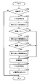
- 5 is a flowchart for illustrating details of a coil switching control process in the first embodiment.
- 5 is a flowchart for illustrating details of a coil switching control process in the first embodiment. It is a figure which shows the detail of the connection in the power receiving unit 500 in a modification. It is an example of the map showing the relationship between the distance between a receiving device and a power transmission unit, and a secondary voltage in a modification. It is an example of the map showing the relationship between the distance between a power receiving apparatus and a power transmission unit, and transmission efficiency in a modification. It is a flowchart for demonstrating the detail of the coil switching control process in a modification. It is a flowchart for demonstrating the detail of the coil switching control process in a modification.
- FIG. 6 is a detailed configuration diagram of a power transmission device 200 according to Embodiment 2.
- FIG. FIG. 10 is a diagram illustrating details in a power transmission unit 220 in the second embodiment.
- FIG. 9 is a functional block diagram for secondary self-resonant coil switching control in the second embodiment.
- 6 is an example of a map representing a relationship between a distance between a power receiving device and a power transmission unit and a secondary voltage in the second embodiment.
- 10 is an example of a map representing a relationship between a distance between a power receiving device and a power transmission unit and transmission efficiency in the second embodiment.
- 10 is a flowchart for explaining details of a coil switching control process in the second embodiment.
- 10 is a flowchart for explaining details of a coil switching control process in the second embodiment.
- FIG. 1 is an overall configuration diagram of a vehicle power supply system 10 according to Embodiment 1 of the present invention.
- vehicle power supply system 10 includes an electric vehicle 100 and a power transmission device 200.
- Electric vehicle 100 includes a power receiving device 110 and a communication unit 130.
- the power receiving device 110 is provided on the bottom surface of the vehicle body, and is configured to receive power transmitted from a power transmission unit 220 (described later) of the power transmission device 200 in a contactless manner.
- the power receiving device 110 includes a self-resonant coil (described later), and receives power from the power transmitting unit 220 in a non-contact manner by resonating with a self-resonant coil included in the power transmitting unit 220 via an electromagnetic field.
- Communication unit 130 is a communication interface for performing communication between electric vehicle 100 and power transmission device 200.
- the power transmission device 200 includes a power supply device 210, a power transmission unit 220, and a communication unit 240.
- the power supply device 210 converts, for example, commercial AC power supplied from a system power supply into high-frequency power and outputs it to the power transmission unit 220.
- the frequency of the high-frequency power generated by the power supply device 210 is, for example, 1 M to several tens of MHz.
- the power transmission unit 220 is provided on the floor of the parking lot, and is configured to send the high-frequency power supplied from the power supply device 210 to the power receiving device 110 of the electric vehicle 100 in a non-contact manner.
- the power transmission unit 220 includes a self-resonant coil (described later) and resonates with the self-resonant coil included in the power receiving apparatus 110 via an electromagnetic field to transmit power to the power receiving apparatus 110 in a contactless manner.
- Communication unit 240 is a communication interface for performing communication between power transmission device 200 and electric vehicle 100.
- high-frequency power is transmitted from the power transmission unit 220 of the power transmission device 200, and the self-resonance coil included in the power reception device 110 of the electric vehicle 100 and the self-resonance coil included in the power transmission unit 220 are electromagnetic fields.
- the electric power is fed from the power transmission device 200 to the electric vehicle 100 by resonating via the power.
- Embodiment 1 power is supplied in advance from power transmission unit 220 to power reception device 110 prior to full-scale power supply, and the distance between power transmission unit 220 and power reception device 110 is detected based on the power supply status. Is done. Then, as will be described later, based on the distance information, control is performed so as to switch a plurality of self-resonant coils included in the power receiving device 110.
- the magnitude of the power transmitted from the power transmission unit 220 when the distance is detected is set smaller than the power supplied from the power transmission unit 220 to the power reception device 110 after switching of the self-resonant coil included in the power reception device 110. .
- FIG. 2 is a diagram for explaining the principle of power transmission by the resonance method.
- this resonance method in the same way as two tuning forks resonate, two LC resonance coils having the same natural frequency resonate in an electromagnetic field (near field), and thereby, from one coil. Electric power is transmitted to the other coil via an electromagnetic field.
- a primary coil 320 that is an electromagnetic induction coil is connected to a high frequency power supply 310, and high frequency power of 1 M to several tens of MHz is fed to a primary self-resonant coil 330 that is magnetically coupled to the primary coil 320 by electromagnetic induction.
- the primary self-resonant coil 330 is an LC resonator having an inductance and stray capacitance of the coil itself, and resonates with a secondary self-resonant coil 340 having the same resonance frequency as the primary self-resonant coil 330 via an electromagnetic field (near field). .
- energy electrical power moves from the primary self-resonant coil 330 to the secondary self-resonant coil 340 via the electromagnetic field.
- the energy (electric power) transferred to the secondary self-resonant coil 340 is taken out by the secondary coil 350 that is an electromagnetic induction coil that is magnetically coupled to the secondary self-resonant coil 340 by electromagnetic induction and supplied to the load 360.
- the resonance method is realized when the Q value indicating the resonance intensity between the primary self-resonant coil 330 and the secondary self-resonant coil 340 is greater than 100, for example.
- the secondary self-resonant coil 340 and the secondary coil 350 correspond to the power receiving device 110 in FIG. 1
- the primary coil 320 and the primary self-resonant coil 330 correspond to the power transmission unit 220 in FIG. 1.
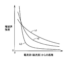
- FIG. 3 is a diagram showing the relationship between the distance from the current source (magnetic current source) and the strength of the electromagnetic field.
- the electromagnetic field includes three components.
- the curve k1 is a component that is inversely proportional to the distance from the wave source, and is referred to as a “radiated electromagnetic field”.
- a curve k2 is a component inversely proportional to the square of the distance from the wave source, and is referred to as an “induction electromagnetic field”.
- the curve k3 is a component inversely proportional to the cube of the distance from the wave source, and is referred to as an “electrostatic magnetic field”.
- the resonance method energy (electric power) is transmitted using this near field (evanescent field). That is, by using a near field to resonate a pair of resonators (for example, a pair of LC resonance coils) having the same natural frequency, one resonator (primary self-resonant coil) and the other resonator (two Energy (electric power) is transmitted to the next self-resonant coil. Since this near field does not propagate energy (electric power) far away, the resonance method transmits power with less energy loss than electromagnetic waves that transmit energy (electric power) by "radiation electromagnetic field” that propagates energy far away. be able to.
- FIG. 4 is a detailed configuration diagram of the electric vehicle 100 shown in FIG.
- electrically powered vehicle 100 includes power storage device 150, system main relay SMR 1, boost converter 162, inverters 164 and 166, motor generators 172 and 174, engine 176, and power split device 177. Drive wheel 178.
- Electric vehicle 100 further includes a power receiving device 110, a rectifier 140, a DC / DC converter 142, a system main relay SMR2, and a voltage sensor 190.
- Electric vehicle 100 further includes a control device 180 and a communication unit 130.
- the power receiving device 110 includes secondary self-resonant coils 112 and 113, a secondary coil 114, a capacitor 116, a switching device 120, and a power receiving ECU (Electronic Control Unit) 185.
- ECU Electric Control Unit
- the electric vehicle 100 is a hybrid vehicle including the engine 176, but is not limited to this configuration. Any vehicle driven by an electric motor can be applied to, for example, an electric vehicle and a fuel cell vehicle. In that case, the engine 176 is not arranged.
- This electric vehicle 100 is equipped with an engine 176 and a motor generator 174 as power sources.
- Engine 176 and motor generators 172 and 174 are connected to power split device 177.
- Electric vehicle 100 travels by a driving force generated by at least one of engine 176 and motor generator 174.
- the power generated by the engine 176 is divided into two paths by the power split device 177. That is, one is a path transmitted to the drive wheel 178 and the other is a path transmitted to the motor generator 172.
- the motor generator 172 is an AC rotating electric machine, for example, a three-phase AC synchronous motor in which a permanent magnet is embedded in a rotor. Motor generator 172 generates power using the kinetic energy of engine 176 divided by power split device 177. For example, when the state of charge of power storage device 150 (also referred to as “SOC (State Of Charge)”) becomes lower than a predetermined value, engine 176 is started, and power is generated by motor generator 172. Device 150 is charged.
- SOC State Of Charge
- the motor generator 174 is also an AC rotating electric machine, and, like the motor generator 172, is, for example, a three-phase AC synchronous motor in which a permanent magnet is embedded in a rotor. Motor generator 174 generates a driving force using at least one of the electric power stored in power storage device 150 and the electric power generated by motor generator 172. Then, the driving force of motor generator 174 is transmitted to driving wheel 178.
- motor generator 174 when braking the vehicle or reducing acceleration on the down slope, the mechanical energy stored in the vehicle as kinetic energy or positional energy is used for rotational driving of the motor generator 174 via the drive wheels 178, and the motor generator 174 is Operates as a generator.
- motor generator 174 operates as a regenerative brake that converts running energy into electric power and generates braking force.
- the electric power generated by motor generator 174 is stored in power storage device 150.
- the power split device 177 includes a planetary gear including a sun gear, a pinion gear, a carrier, and a ring gear.
- the pinion gear engages with the sun gear and the ring gear.
- the carrier supports the pinion gear so as to be able to rotate and is coupled to the crankshaft of the engine 176.
- the sun gear is coupled to the rotation shaft of motor generator 172.
- the ring gear is connected to the rotation shaft of motor generator 174 and drive wheel 178.
- the power storage device 150 is a rechargeable DC power source, and is composed of, for example, a secondary battery such as lithium ion or nickel metal hydride. Power storage device 150 stores electric power supplied from DC / DC converter 142 and also stores regenerative power generated by motor generators 172 and 174. Power storage device 150 supplies the stored power to boost converter 162. Note that a large-capacity capacitor can also be used as the power storage device 150, and temporarily stores the power supplied from the power transmission device 200 (FIG. 1) and the regenerative power from the motor generators 172 and 174, and boosts the stored power. Any power buffer that can be supplied to the converter 162 may be used.
- System main relay SMR1 is provided between power storage device 150 and boost converter 162.
- System main relay SMR1 electrically connects power storage device 150 to boost converter 162 when signal SE1 from control device 180 is activated, and power storage device 150 and boost converter when signal SE1 is deactivated. The electric path to 162 is cut off.
- Boost converter 162 boosts the voltage on positive line PL ⁇ b> 2 to a voltage equal to or higher than the voltage output from power storage device 150 based on signal PWC from control device 180.
- Boost converter 162 is formed of a DC chopper circuit, for example.
- Inverters 164 and 166 are provided corresponding to motor generators 172 and 174, respectively.
- Inverter 164 drives motor generator 172 based on signal PWI 1 from control device 180, and inverter 166 drives motor generator 174 based on signal PWI 2 from control device 180.
- Inverters 164 and 166 include, for example, a three-phase bridge circuit.
- the secondary self-resonant coils 112 and 113 are coils having the same resonance frequency and different coil diameters, as will be described later. Secondary self-resonant coils 112 and 113 have one end connected to each other and the other end connected to connection ends T1 and T2 of switching device 120, respectively.
- one end of the capacitor 116 is further connected to the connection node of the secondary self-resonant coils 112 and 113, and the other end is connected to the connection end T10 of the switching device 120.
- the switching device 120 switches the connection end to which the capacitor 116 is connected to one of the connection ends of the secondary self-resonant coils 112 and 113 in accordance with the switching command SEL1 from the power receiving ECU 185. At this time, switching device 120 outputs to signal receiving ECU 185 a signal POS1 indicating which secondary self-resonant coil is being switched to.
- the secondary self-resonant coils 112 and 113 are connected to the capacitor 116 by the switching device 120, they become LC resonant coils in which the capacitor 116 is connected to both ends of the coil. Then, power is received from the power transmission device 200 by resonating with a primary self-resonant coil (described later) of the power transmission device 200 via an electromagnetic field.
- the capacitor 116 is not disposed and the secondary self-resonant coil is not provided.
- 112 and 113 are in a state where both ends of the coil are not connected (open).
- a secondary self-resonant coil 112 113 is provided with a relay (not shown) that can divide the coil in the vicinity of the center of each coil.
- the relay contact is closed, and for the unused secondary self-resonance coil, the relay contact is opened.
- the secondary self-resonant coils 112 and 113 are based on the distance from the primary self-resonant coil of the power transmission device 200, the resonant frequencies of the primary self-resonant coils and the secondary self-resonant coils 112 and 113, and the like. And the number of turns are appropriately set so that the Q value (for example, Q> 100) indicating the resonance strength between the secondary self-resonant coils 112 and 113 and ⁇ indicating the degree of coupling are increased.
- Q value for example, Q> 100
- the secondary coil 114 is provided coaxially with the secondary self-resonant coils 112 and 113, and can be magnetically coupled to the secondary self-resonant coils 112 and 113 by electromagnetic induction.
- the secondary coil 114 takes out the electric power received by the secondary self-resonant coils 112 and 113 by electromagnetic induction and outputs it to the rectifier 140.
- the rectifier 140 rectifies the AC power extracted by the secondary coil 114. Based on signal PWD from control device 180, DC / DC converter 142 converts the power rectified by rectifier 140 into a voltage level of power storage device 150 and outputs the voltage level to power storage device 150.
- System main relay SMR ⁇ b> 2 is provided between DC / DC converter 142 and power storage device 150.
- System main relay SMR2 electrically connects power storage device 150 to DC / DC converter 142 when signal SE2 from control device 180 is activated, and power storage device 150 when signal SE2 is deactivated. The electric circuit between the DC / DC converter 142 is cut off.
- Voltage sensor 190 detects voltage VH between rectifier 140 and DC / DC converter 142 and outputs the detected value to control device 180 and power receiving ECU 185.
- Control device 180 generates signals PWC, PWI1, and PWI2 for driving boost converter 162 and motor generators 172 and 174, respectively, based on the accelerator opening, vehicle speed, and other signals from various sensors.
- the signals PWC, PWI1, and PWI2 are output to boost converter 162 and inverters 164 and 166, respectively.
- control device 180 activates signal SE1 to turn on system main relay SMR1, and deactivates signal SE2 to turn off system main relay SMR2.
- control device 180 receives information (voltage and current) of the power transmitted from the power transmission device 200 from the power transmission device 200 via the communication unit 130.
- the detection value of voltage VH detected by voltage sensor 190 is received from voltage sensor 190. Based on these data, control device 180 performs vehicle parking control and the like so as to guide the vehicle to power transmission unit 220 (FIG. 1) of power transmission device 200.
- the power receiving ECU 185 receives power information (such as voltage and current) transmitted from the power transmission device 200 from the power transmission device 200 via the communication unit 130, and receives a detection value of the voltage VH detected by the voltage sensor 190 from the voltage sensor 190. receive. Then, power reception ECU 185 detects the distance between power reception device 110 and power transmission unit 220 (FIG. 1) based on these pieces of information. Then, based on the detected distance between power reception device 110 and power transmission unit 220 (FIG. 1), switching device 120 is controlled to select one of secondary self-resonant coils 112 and 113. This coil switching control will be described later with reference to FIG.
- power information such as voltage and current
- control device 180 transmits a power supply command to power transmission device 200 via communication unit 130, and signal SE2 Is activated to turn on the system main relay SMR2. Then, control device 180 generates a signal PWD for driving DC / DC converter 142 and outputs the generated signal PWD to DC / DC converter 142.
- control device 180 and the power receiving ECU 185 include a CPU (Central Processing Unit), a storage device, and an input / output buffer, and input each sensor and output a control command to each device.
- the electric vehicle 100 and each device are controlled. Note that these controls are not limited to software processing, and a part of them can be constructed and processed by dedicated hardware (electronic circuit).
- control device 180 and the power receiving ECU 185 are configured as separate control devices.
- the configuration is not limited to such a configuration, and the control device 180 and the power receiving ECU 185 are configured as one control device. May be. Also, some functions of the control device 180 may be further divided into separate control devices.
- FIG. 5 is a detailed configuration diagram of the power transmission device 200 shown in FIG.
- power transmission device 200 includes AC power supply 250, high-frequency power driver 260, primary coil 222, primary self-resonant coil 224, voltage sensor 272, current sensor 274, communication unit 240, Power transmission ECU 270 and capacitor 280 are included.
- AC power supply 250 is a power supply external to the vehicle, for example, a commercial power supply.
- the high frequency power driver 260 converts the power received from the AC power source 250 into high frequency power, and supplies the converted high frequency power to the primary coil 222.
- the frequency of the high-frequency power generated by the high-frequency power driver 260 is, for example, 1 M to several tens of MHz.
- the primary coil 222 is provided coaxially with the primary self-resonant coil 224 and can be magnetically coupled to the primary self-resonant coil 224 by electromagnetic induction.
- the primary coil 222 feeds high-frequency power supplied from the high-frequency power driver 260 to the primary self-resonant coil 224 by electromagnetic induction.
- the primary self-resonant coil 224 is connected to a capacitor 280 at both ends to constitute an LC resonant coil. Then, electric power is transmitted to the electric vehicle 100 by resonating with the secondary self-resonant coils 112 and 113 of the electric vehicle 100 via an electromagnetic field.
- the capacitor 280 is not arranged, and the primary self-resonant coil 224 is disconnected at both ends of the coil ( Open).
- the primary self-resonant coil 224 also has a Q value (based on the distance from the secondary self-resonant coils 112 and 113 of the electric vehicle 100, the resonance frequency of the primary self-resonant coil 224 and the secondary self-resonant coils 112 and 113, and the like. For example, the number of turns is appropriately set so that Q> 100) and the degree of coupling ⁇ and the like are increased.
- the primary self-resonant coil 224 and the primary coil 222 form the power transmission unit 220 shown in FIG.
- Voltage sensor 272 detects voltage VS output from high-frequency power driver 260 and outputs the detected value to power transmission ECU 270.
- Current sensor 274 detects current IS output from high-frequency power driver 260 and outputs the detected value to power transmission ECU 270.
- the power transmission ECU 270 When the power transmission ECU 270 receives an activation command from the electric vehicle 100 via the communication unit 240, the power transmission ECU 270 activates the power transmission device 200. When the power transmission ECU 270 receives a power supply start command from the electric vehicle 100 via the communication unit 240, the power transmission ECU 270 outputs the output of the high-frequency power driver 260 so that the electric power supplied from the power transmission device 200 to the electric vehicle 100 matches the target value. Control.
- the power transmission ECU 270 receives a test signal output command for detecting the distance between the power receiving device 110 (FIG. 1) and the power transmission unit 220 from the electric vehicle 100 via the communication unit 240. Power information of power transmission device 200 including detected values of voltage VS and current IS from current sensor 274 is transmitted to electric vehicle 100 via communication unit 240. Then, during reception of the test signal output command, the power transmission ECU 270 controls the output of the high-frequency power driver 260 so as to output a predetermined power smaller than the power at the time of power feeding based on the power feeding start command.
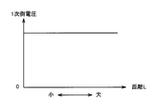
- FIG. 6 is a diagram showing the relationship between the distance between the power receiving apparatus 110 and the power transmission unit 220 and the primary voltage (output voltage from the power transmission apparatus 200).
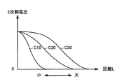
- FIG. 7 is a diagram showing the relationship between the distance between the power reception device 110 and the power transmission unit 220 and the secondary voltage (power reception voltage of the electric vehicle 100).
- the secondary side voltage received by electric vehicle 100 is equal to the constant primary side voltage as shown in FIG. 6, and power transmission unit 220 of power transmission device 200 and power reception device 110 of electric vehicle 100 are shown. It changes according to the distance L between. Therefore, a map or the like measured in advance by experiments or the like for the relationship between the primary side voltage and the secondary side voltage as shown in FIGS. 6 and 7 corresponding to the primary self-resonant coil 224 on the power transmission unit 220 side is stored. The distance between the power transmission unit 220 and the power receiving apparatus 110 can be detected by referring to this map based on the detected value of the voltage VH indicating the secondary side voltage. Information on primary self-resonant coil 224 is included in the power information transmitted from power transmission ECU 270 to electric vehicle 100 via communication unit 240 described above.
- the secondary side voltage received by the electric vehicle 100 changes, for example, as C10, C20, C30 in FIG. 7 as the coil diameter of the secondary self-resonant coil increases.
- the coil diameter of the secondary self-resonant coil in the case of C10 is the smallest, and the coil diameter in the case of C30 is the largest.
- the detectable distance increases as the coil diameter of the secondary self-resonant coil increases, but the accuracy at a short distance decreases.
- the smaller the coil diameter the smaller the detectable distance, but the accuracy at a short distance is improved.
- a plurality of secondary self-resonant coils having different coil diameters can be switched and used to perform accurate distance detection from far to short distances.
- the power transmission device is used using this relationship.
- the distance between the power transmission unit 220 and the power receiving device 110 may be detected based on the detected value of the output current from 200.
- FIG. 9 shows an external view of the power receiving unit 500 for explaining the outline of the arrangement of the secondary self-resonant coils 112 and 113 and the secondary coil 114 included in the power receiving device 110 in the first embodiment.
- power receiving unit 500 includes secondary self-resonant coils 112 and 113, secondary coil 114, capacitor 116, bobbins 410 and 420, and coil case 510.
- the bobbins 410 and 420 are cylindrical insulators having different diameters.
- the diameter of the bobbin 410 is smaller than the diameter of the bobbin 420 and is disposed concentrically in the coil case 510.
- the secondary self-resonant coils 112 and 113 are coils having the same resonance frequency. Secondary self-resonant coils 112 and 113 are wound around bobbins 410 and 420, respectively. In addition, by making the resonance frequency of each secondary self-resonant coil the same, it is possible to use any secondary self-resonant coil without changing the primary self-resonant coil 224 on the power transmission unit 220 side. Can be performed. Note that the resonance frequency of each secondary self-resonant coil may not be completely the same as long as electromagnetic resonance with the power transmission unit is possible, but may be slightly different.
- the capacitor 116 is provided inside the bobbin 410 having the smallest diameter.
- One capacitor 116 is provided in the power receiving unit 500 and is provided in common to the secondary self-resonant coils 112 and 113.
- the LC resonance circuit is configured by being switched by the switching device 120 (FIG. 4) and connected to both ends of the secondary self-resonant coil 112 or the secondary self-resonant coil 113.
- the secondary coil 114 is provided coaxially with the bobbin 410 having the smallest diameter. Secondary coil 114 is provided in common with secondary self-resonant coils 112 and 113. Then, both ends of the secondary coil are drawn out of the coil case 510 and connected to the rectifier 140 (FIG. 4).
- the coil case 510 is formed in a box shape, for example, and houses the secondary self-resonant coils 112 and 113, the secondary coil 114, the capacitor 116, and the bobbins 410 and 420.
- an electromagnetic shielding material (not shown) is provided on each surface except the surface facing the power transmission unit 220.
- the electromagnetic shielding material is a low-impedance material, and for example, copper foil or the like is used.
- the shape of the coil case 510 is not limited to the shape of the rectangular parallelepiped shown in FIG. 9 as long as the secondary self-resonant coils 112 and 113, the secondary coil 114, the capacitor 116, and the bobbins 410 and 420 can be accommodated. .
- Other examples of the shape of the coil case 510 include a cylindrical shape and a cylindrical shape having a polygonal cross section.
- the two secondary self-resonant coils 112 and 113 are concentrically arranged, and the capacitor 116, the secondary coil 114, and the coil case 510 are configured in common, thereby providing a plurality of secondary self-resonant coils. Even when the power receiving unit 500 is provided, the size of the power receiving unit 500 can be reduced and the cost can be reduced.
- FIG. 10 is a cross-sectional view perpendicular to the central axis CL10 of the power receiving unit 500 shown in FIG.
- one end of secondary self-resonant coils 112 and 113 are both connected to one end T20 of capacitor 116.
- the other ends of secondary self-resonant coils 112 and 113 are connected to connection terminals T1 and T2 of switching device 120, respectively.
- connection terminal T10 of the switching device 120 The other end of the capacitor 116 is connected to the connection terminal T10 of the switching device 120. Then, the switching device 120 switches so that the connection terminal T10 is connected to the connection terminal T1 or T2.
- the displacement (distance) between the primary self-resonant coil on the power transmission side and the secondary self-resonant coil on the power receiving side affects transmission efficiency. Specifically, the transmission efficiency is improved when the distance between the primary self-resonant coil and the secondary self-resonant coil is as short as possible.
- the driver's parking operation causes the resonator on the power transmission side (ground side) and the self-resonant coil on the power receiving side (vehicle side) to be aligned. Done. Therefore, depending on the driver, it may be relatively difficult to precisely align both resonators, and it is also necessary to allow a certain degree of displacement.
- a self-resonant coil with a wide transmission range (for example, a coil with a large coil diameter) is used as much as possible in order to allow power transmission even if the primary self-resonant coil and the secondary self-resonant coil are misaligned. It is necessary to do.
- the coil having a wide transmission range has a relatively low power transfer performance, the transmission efficiency is low.
- the transmission efficiency is Although the transmission range is narrow, the transmission efficiency is lower than that of a coil having a wide transmission range when the positional deviation is large because the transmission range is narrow.
- the positional shift (distance) between the primary self-resonant coil and the secondary self-resonant coil is accurately detected, and the secondary power is transmitted efficiently based on the detected distance.
- Switching control for switching the self-resonant coil is performed.
- FIG. 11 shows a functional block diagram of secondary self-resonant coil switching control performed by power receiving ECU 185 in the first embodiment.
- Each functional block described in FIG. 11 is realized by hardware or software processing by the power receiving ECU 185.
- power reception ECU 185 includes a distance detection unit 600, a storage unit 610, a determination unit 620, a switching control unit 630, and a power supply start command unit 640.
- the determination unit 620 includes a distance detection coil determination unit 621 and a power reception coil determination unit 622.
- the distance detection unit 600 receives the received voltage (secondary voltage) VH from the voltage sensor 190, the signal PRK indicating that the parking of the electric vehicle 100 from the control device 180 is completed, and the current switching from the switching device 120. A signal POS1 representing the position is received as an input.
- the distance detection unit 600 receives the primary voltage VS of the distance detection test signal transmitted from the power transmission device 200 as an input via the communication unit 130.
- the distance detection part 600 will turn on and output the test signal output instruction
- the power transmission device 200 outputs predetermined power smaller than the power at the time of power supply execution based on the power supply start command while the test signal output command TSTFLG1 is on.
- the distance detection unit 600 turns on and outputs a test signal output command TSTFLG1 to the determination unit 620 so as to output a test signal for distance detection.
- the distance detection unit 600 is based on the primary voltage VS of the test signal output from the power transmission device 200, the secondary voltage VH detected by the voltage sensor 190, and the switching position POS1 of the switching device 120. A distance L between the power transmission unit 220 and the power receiving apparatus 110 is detected. Then, the detected distance L is output to the determination unit 620. When the detection distance L is finally determined, the test signal output command TSTFLG1 is turned off.
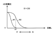
- the distance detection unit 600 detects the distance L according to a map stored in advance in the storage unit 610 as shown in FIG.
- FIG. 12 is an example of a map stored in the storage unit 610 used for the above distance detection at a certain primary voltage.
- a curve W1 indicates a secondary side voltage detected by a secondary self-resonant coil 112 having a small coil diameter (hereinafter also referred to as “first coil”), and a curve W2 is a secondary having a large coil diameter.
- the secondary voltage detected by the self-resonant coil 113 (hereinafter also referred to as “second coil”) is shown.
- the distance detection unit 600 first detects the distance L using the second coil having a long detectable distance.
- the detected distance L is a distance that can be detected by the first coil
- the secondary self-resonant coil used for distance detection by the switching control unit 630 is used as the first coil as described later.
- the distance L is detected again using the first coil with higher accuracy.
- determination unit 620 receives distance L detected from distance detection unit 600 and test signal output command TSTFLG1 as inputs.
- the distance detection coil determination unit 621 determines whether the first coil and the first coil depend on whether the detected distance L is smaller than a predetermined threshold value. It is determined which of the two coils the distance detection value using is used.
- the distance detection coil determination unit 621 refers to the map as shown in FIG. 12 stored in the storage unit 610, and if the distance L detected by the second coil is equal to or greater than A1, the distance detection coil determination unit 621 It is determined to adopt the distance detected by the coil, and when the distance L is smaller than A1, it is determined to adopt the distance detected by the first coil. Then, the distance detection coil determination unit 621 outputs a coil determination signal CIL1 as a determination result to the switching control unit 630.
- the power receiving coil determination unit 622 uses the first coil based on the distance L between the power transmission unit 220 and the power receiving device 110. It is determined which of the second coil and the second coil is used for power reception.
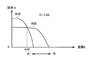
- the power receiving coil determination unit 622 refers to a map showing the relationship between the distance L and the power transmission efficiency ⁇ stored in the storage unit 610 as shown in FIG. A coil with a high transmission efficiency ⁇ is selected.
- a curve W10 indicates the transmission efficiency of the first coil
- a curve W20 indicates the transmission efficiency of the second coil.
- the smaller the coil diameter the higher the transmission efficiency, but the shorter feedable distance.
- the coil diameter is large, the transmission efficiency is relatively lowered, but the power feedable distance is increased. Then, when the detection distance L is smaller than the distance (for example, A10 in FIG.
- power reception coil determination unit 622 outputs a coil determination signal CIL10 as a determination result to switching control unit 630 and power supply start command unit 640.
- the switching control unit 630 outputs a coil switching command SEL1 to the switching device 120 based on the coil determination signal CIL1 input from the determination unit 620 when detecting the distance.
- the switching control unit 630 outputs a coil switching command SEL1 to the switching device 120 based on the coil determination signal CIL10 input from the determination unit 620.
- the switching device 120 switches the coil used for distance detection and the coil used for power reception according to the switching signal SEL1.
- the power supply start command unit 640 receives the coil determination signal CIL10 used for power reception from the determination unit 620 as an input. When coil determination signal CIL10 is set, power supply start command unit 640 outputs power supply start signal CHG to power transmission device 200 via communication unit 130.
- the threshold value (A1 in FIG. 12) used for coil switching determination in the case of distance detection and the threshold value (A10 in FIG. 13) used for switching determination of the coil used for power reception. Can be set to the same value.
- FIGS. 15, 19, and 20 which will be described later, starting with FIG. 14, a program stored in advance in the power receiving ECU 185 is called from the main routine and executed at a predetermined cycle. Alternatively, for some steps, it is also possible to construct dedicated hardware (electronic circuit) and realize processing.
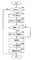
- step 700 power receiving ECU 185 at step 700 (hereinafter, “S”) 700, based on signal PRK indicating that parking of electric vehicle 100 has been completed, It is determined whether or not parking has been completed.
- the power receiving ECU 185 selects the second coil having a long detectable distance in S720 and detects the distance L between the power receiving apparatus 110 and the power transmission unit 220 (FIG. 1).
- power receiving ECU 185 determines whether or not detected distance L is smaller than A1 by referring to the map shown in FIG. 12 stored in storage unit 610 based on detected distance L. .
- power receiving ECU 185 switches to the first coil having high distance detection accuracy at short distance by switching device 120 and performs distance detection again (S740).
- the power receiving ECU 185 determines the distance L detected by the first coil as the distance L between the power receiving device 110 and the power transmission unit 220 (FIG. 1) in S750. Then, the process proceeds to S760, and the test signal output command is turned off.
- the power receiving ECU 185 outputs a power supply start command CHG to the power transmission device 200 (FIG. 1) so as to start power supply using the currently selected first coil (S770).
- step S740 is skipped and the process proceeds to S750.
- the distance L detected by the second coil is determined as the distance L between the power receiving apparatus 110 and the power transmission unit 220 (FIG. 1) (S750).
- the power receiving ECU 185 turns off the test signal output command TSTFLG1 (S760), and also starts a power supply start command to the power transmission device 200 (FIG. 1) so as to start power supply using the selected second coil.
- CHG is output (S770).
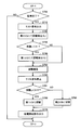
- FIG. 15 a case will be described in which the threshold value for determining the coil used for distance detection (A1 in FIG. 12) is different from the threshold value for determining the coil used for power reception (A10 in FIG. 13).
- the flowchart shown in FIG. 15 is obtained by adding S761, S765, and S766 to the flowchart of FIG. Note that the description of the same steps as those in FIG. 14 will not be repeated.
- the power receiving ECU 185 proceeds to S761, and determines whether the determined distance L is smaller than A10.
- power reception ECU 185 switches the coil used for power reception to the first coil having relatively high transmission efficiency ⁇ at a short distance.
- power receiving ECU 185 outputs power supply start command CHG to power transmission device 200 (FIG. 1).
- power reception ECU 185 switches the coil used for power reception to the second coil that has relatively high transmission efficiency ⁇ at a long distance.
- power receiving ECU 185 outputs power supply start command CHG to power transmission device 200 (FIG. 1).
- the power receiving device 110 includes the plurality of secondary self-resonant coils 112 and 113, and switches these secondary self-resonant coils 112 and 113.
- the distance between the power receiving device 110 and the power transmission unit 220 can be accurately detected from a long distance to a short distance, and transmission efficiency can be improved in power transmission by the resonance method.
- FIG. 16 is a diagram illustrating details of connection in the power receiving unit 500 corresponding to FIG. 10 in the first embodiment.
- a secondary self-resonant coil 115 (hereinafter also referred to as “third coil”) having a larger coil diameter than the secondary self-resonant coil 113 (second coil) in FIG. 10 and a third coil are mounted.
- the bobbin 430 is further provided, and the first coil, the second coil, and the third coil are all housed in one coil case 510. Accordingly, the switching device 120 that has switched between two contacts is changed to a switching device 120 # that can switch between three contacts. Note that the description of the same parts as those in FIG. 10 will not be repeated.
- bobbin 430 is provided concentrically with bobbins 410 and 420.
- the secondary self-resonant coil 115 is wound around the bobbin 430 and attached.
- one ends of the secondary self-resonant coils 112, 113 and 115 are all connected to one end T 20 of the capacitor 116.
- the other ends of secondary self-resonant coils 112, 113, and 115 are connected to connection terminals T1 #, T2 #, and T3 # of switching device 120 #, respectively.
- connection terminal T10 # of the switching device 120 # The other end of the capacitor is connected to the connection terminal T10 # of the switching device 120 #. Then, switching device 120 # switches so that connection terminal T10 # is connected to any one of connection terminals T1 #, T2 #, and T3 #.
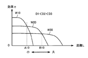
- FIGS. 17 and 18 correspond to FIGS. 12 and 13 in the first embodiment, respectively, and show the relationship between the distance between the power receiving device 110 and the power transmission unit 220, the secondary side voltage VH, and the transmission efficiency ⁇ , respectively. It is a thing. 17 and 18, curves W3 and W30 for the third coil are added respectively.
- the curve W3 corresponds to the third coil, and distance detection is performed by the third coil when the detected distance L is equal to or greater than the threshold value B1.
- distance detection is performed by the second coil.
- the curve W30 corresponds to the third coil, and when the determined distance L is equal to or greater than the threshold value B10, power is received by the third coil. When the distance L is smaller than the threshold value B10 and greater than or equal to A10, power is received by the second coil.
- a flowchart showing details of the coil switching control process is shown.
- FIG. 19 is obtained by adding S711 and S712 to FIG. 14 of the first embodiment. The description of the same steps as those in FIG. 14 will not be repeated.
- power receiving ECU 185 when power receiving ECU 185 outputs a test signal output command in S710, power receiving ECU 185 proceeds to S711, and first selects a third coil that can detect the distance to the farthest and performs distance detection.
- the processes of S720 to S740 are skipped and the process proceeds to S750.
- power reception ECU 185 determines distance L detected by the third coil as distance L between power reception device 110 and power transmission unit 220, and turns off the test signal output command in S760.
- a power supply start command CHG is output to the power transmission device 200 so as to start power supply using the currently selected third coil (S770).
- FIG. 20 shows the details of the coil switching control process when the threshold for determining the coil for detecting the distance is different from the threshold for determining the coil for receiving power (that is, A1 ⁇ A10, B1 ⁇ B10).
- a flowchart showing is shown.
- FIG. 20 is obtained by adding S711, S712, S762, and S767 to FIG. 15 in the first embodiment. Of these, S711 and S712 are the same as in FIG. Note that the description of the same steps as those in FIGS. 15 and 19 will not be repeated.
- power receiving ECU 185 advances the process to S761, where the determined distance L is smaller than A10. Determine whether or not.
- power reception ECU 185 switches the coil used for power reception to the first coil. Then, the process proceeds to S770.
- power reception ECU 185 switches the coil used for power reception to the second coil. Then, the process proceeds to S770.
- power reception ECU 185 switches the coil used for power reception to the third coil. Then, the process proceeds to S770.
- the power receiving ECU 185 outputs a power supply start command CHG to the power transmission device 200.
- this coil switching control can be applied even when there are three secondary self-resonant coils.
- the third coil having a larger coil diameter is added.
- a coil having a coil diameter between the coil diameter of the first coil and the coil diameter of the second coil is added.
- a coil having a smaller coil diameter than the first coil may be added.
- four or more secondary self-resonant coils may be included.
- FIG. 21 shows a detailed configuration diagram of the power transmission device 200 according to the second embodiment.
- the primary self-resonant second coil 25 and the switching device 230 are added to the power transmission unit 220 of FIG. 5 in the first embodiment.
- the description of the same part as in FIG. 5 will not be repeated.
- primary self-resonant coils 224 and 225 are coils having the same resonance frequency and different coil diameters.
- Primary self-resonant coils 224 and 225 have one end connected to each other and the other end connected to connection ends T1 * and T2 * of switching device 230, respectively.
- one end of the capacitor 280 is further connected to the connection node of the primary self-resonant coils 224 and 225, and the other end is connected to the connection end T10 * of the switching device 230.
- the switching device 230 switches the connection end to which the capacitor 280 is connected to connect to one of the connection ends of the primary self-resonant coils 224 and 225 according to the switching command SEL2 of the power transmission ECU 270.
- switching device 230 outputs to signal transmission ECU 270 a signal POS2 indicating which primary self-resonant coil is being switched to.
- the primary self-resonant coils 224 and 225 are connected to the capacitor 280 by the switching device 230, they become LC resonant coils in which the capacitor 280 is connected to both ends of the coil. Then, power is transmitted to the power receiving device 110 by resonating with the secondary self-resonant coil of the power receiving device 110 via an electromagnetic field.
- FIG. 22 is a cross-sectional view of power transmission unit 220 as in FIG. 10 of the first embodiment.
- FIG. 9 corresponds to the primary coil 222
- the secondary self-resonant coils 112 and 113 correspond to the primary self-resonant coils 224 and 225.
- the capacitor 116 corresponds to the capacitor 280
- the coil case 510 corresponds to the coil case 520.
- the bobbins 410 and 420 correspond to the bobbins 440 and 450
- the switching device 120 corresponds to the switching device 230. Note that the detailed description of each device will not be repeated.
- one end of primary self-resonant coils 224 and 225 are both connected to one end T20 * of capacitor 280.
- the other ends of primary self-resonant coils 224 and 225 are connected to connection terminals T1 * and T2 * of switching device 230, respectively.
- the other end of the capacitor 280 is connected to the connection terminal T10 * of the switching device 230. Then, the switching device 230 switches so that the connection terminal T10 * is connected to the connection terminal T1 * or T2 *.
- FIG. 23 shows a functional block diagram of primary self-resonant coil switching control performed by power transmission ECU 270 in the second embodiment.
- Each functional block described in FIG. 23 is realized by hardware or software processing by power transmission ECU 270.
- power transmission ECU 270 includes a distance detection unit 650, a storage unit 660, a determination unit 670, a switching control unit 680, and a power supply control unit 690.
- Determination unit 670 includes a distance detection coil determination unit 671 and a power reception coil determination unit 672.
- the distance detection unit 650 receives the power transmission voltage (primary side voltage) VS from the voltage sensor 272 and the signal POS2 indicating the current switching position from the switching device 230 as inputs. In addition, the distance detection unit 650 transmits a signal PRK indicating that parking of the electric vehicle 100 is completed via the communication unit 240, and a secondary side voltage VH with respect to a test signal for distance detection detected by the power receiving device 110. As input.
- test signal output command TSTFLG2 for outputting a test signal for distance detection to determination unit 670 and power supply control unit 690. Is output as on. While the test signal output command TSTFLG2 is on, the power supply control unit 690 outputs a predetermined power smaller than the power at the time of power supply execution based on the power supply start command from the electric vehicle.
- the distance detection unit 650 is configured to transmit power to the power transmission unit 220 based on the secondary voltage VH for the test signal received from the power receiving device 110, the primary voltage VS detected by the voltage sensor 272, and the switching position POS2 of the switching device 230.
- the distance L ⁇ b> 2 with the power receiving apparatus 110 is detected, and the detected distance L ⁇ b> 2 is output to the determination unit 670.
- the test signal output command TSTFLG2 is turned off.
- the distance detection unit 650 detects the distance L2 according to a map stored in advance in the storage unit 660 as shown in FIG.
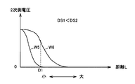
- FIG. 24 is an example of a map stored in the storage unit 660 used for the above distance detection at a certain primary voltage.
- a curve W5 indicates a secondary side voltage detected by the power receiving device 110 when a primary self-resonant coil 224 (hereinafter also referred to as “fourth coil”) having a small coil diameter is used
- a curve W6 Indicates a secondary voltage detected by the power receiving device 110 when a primary self-resonant coil 225 having a large coil diameter (hereinafter also referred to as “fifth coil”) is used.
- the accuracy of the detectable distance and the detection distance varies depending on the coil diameter of the primary self-resonant coil used for power transmission. Therefore, the distance detection unit 650 first performs power transmission using the fifth coil having a long detectable distance, and detects the distance L2. When distance detection is possible even with power transmission using the fourth coil, the switching control unit 680 switches the coil used for distance detection to the fourth coil, and the distance detection unit 650 transmits power using the fourth coil. Thus, the distance L2 is detected with higher accuracy.
- determination unit 670 receives distance L2 detected by distance detection unit 650 and test signal output command TSTFLG2 as inputs.
- the distance detection coil determination unit 671 determines whether the fourth coil and the second coil depend on whether the detected distance L2 is smaller than a predetermined threshold value. It is determined which of the five coils is used for distance detection.
- the distance detection coil determination unit 671 refers to the map shown in FIG. 24 stored in the storage unit 660, and if the distance L2 detected by the fifth coil is greater than or equal to D1, It is determined to adopt the distance detected by the coil. On the other hand, when the distance L2 is smaller than D1, the distance detection coil determination unit 671 determines to adopt the distance detected by the fourth coil. Then, the distance detection coil determination unit 671 outputs a coil determination signal CIL2 as a determination result to the switching control unit 680.
- the power transmission coil determination unit 672 determines the fourth coil and the fourth coil based on the distance L2 between the power transmission unit 220 and the power receiving device 110. It is determined which of the fifth coils is used for power transmission.
- the power transmission coil determination unit 672 refers to a map showing the relationship between the distance L2 and the power transmission efficiency ⁇ as shown in FIG. 25, and the primary in which the transmission efficiency ⁇ increases at the detected distance L2. Select a self-resonant coil.
- a curve W50 indicates the transmission efficiency of the fourth coil
- a curve W60 indicates the transmission efficiency of the fifth coil.
- the smaller the coil diameter the higher the transmission efficiency, but the shorter power supply distance.
- the coil diameter is large, the transmission efficiency is relatively lowered, but the power feedable distance is increased. If the detection distance L2 is smaller than the distance (for example, D10 in FIG.
- power transmission coil determination unit 672 outputs coil determination signal CIL20, which is the determination result, to switching control unit 680 and power supply control unit 690.
- the switching control unit 680 outputs a coil switching command SEL2 to the switching device 230 based on the coil determination signal CIL2 input from the determination unit 670 when detecting the distance. Further, at the time of power transmission, the switching control unit 680 outputs a coil switching command SEL2 to the switching device 230 based on the coil determination signal CIL20 input from the determination unit 670.
- the switching device 230 switches a coil used for distance detection and a coil used for power transmission according to the switching signal SEL2.
- the power supply control unit 690 controls the high-frequency power driver 260 to perform power supply for distance detection.
- high-frequency power driver 260 is controlled to perform full-scale power supply.
- the threshold value (D1 in FIG. 24) used for coil switching determination in the case of distance detection and the threshold value (D10 in FIG. 25) used for switching determination of the coil used for power transmission. Can be set to the same value. In this case, determination of the coil to be used for power transmission by the determination unit 670 is omitted, and the coil that has finally detected the distance is set as the coil to be used for power transmission and power feeding is started.
- FIGS. 26 and 27 show flowcharts for explaining the details of the coil switching control process by the power transmission ECU 270.
- power transmission ECU 270 has completed parking of electric vehicle 100 (FIG. 1) received from electric vehicle 100 (FIG. 1) via communication unit 240 in S800. It is determined whether or not the parking of the electric vehicle 100 (FIG. 1) is completed based on the signal PRK indicating the above.
- the power transmission ECU 270 detects the distance L2 between the power receiving device 110 (FIG. 1) and the power transmission unit 220 by selecting the fifth coil in the distance detection unit 650 in S820.
- power transmission ECU 270 determines whether or not the detected distance is smaller than D1 by referring to the map as shown in FIG. 24 stored in storage unit 660 based on detected distance L2. .
- power transmission ECU 270 determines distance L2 detected by the fourth coil as distance L2 between power receiving device 110 (FIG. 1) and power transmission unit 220, and turns off test signal output command TSTFLG2 in S860.
- step S840 is skipped and the process proceeds to S850. Then, the distance L2 detected by the fifth coil is determined as the distance L2 between the power receiving apparatus 110 (FIG. 1) and the power transmission unit 220. Then, in S860, the test signal output command TSTFLG2 is turned off, and power feeding is started using the selected fifth coil (S870).
- FIG. 27 a case will be described where the threshold value for determining the coil used for distance detection (D1 in FIG. 24) and the threshold value for determining the coil used for power transmission (D10 in FIG. 25) are different.
- the flowchart shown in FIG. 27 is obtained by adding S861, S865, and S866 to the flowchart of FIG. Note that the description of the same steps as those in FIG. 26 will not be repeated.
- the power transmission ECU 270 proceeds to S861 and determines whether the determined distance L2 is smaller than D10.
- power transmission ECU 270 switches the coil used for power transmission to the fourth coil. In S870, power transmission ECU 270 starts power feeding.
- power transmission ECU 270 switches the coil used for power transmission to the fifth coil. In S870, power transmission ECU 270 starts power feeding.
- the power transmission unit 220 includes a plurality of primary self-resonant coils 224 and 225, detects the distance between the power receiving apparatus 110 and the power transmission unit 220, and transmits power according to the detected distance.
- the distance between the power receiving apparatus 110 and the power transmission unit 220 can be accurately detected, and the transmission efficiency can be improved in the transmission of power by the resonance method.
- the primary self-resonant coil or the secondary self-resonant coil may be set to be switched preferentially by the driver's selection, or other conditions (for example, coil specifications, etc.)
- the coil to be switched may be automatically selected according to the above.
- the coil diameters of both the primary self-resonant coil and the secondary self-resonant coil may be switched, and the combination of the respective coil diameters used in the primary self-resonant coil and the secondary self-resonant coil may be changed.
- the primary coils 222 and 320 and the secondary coils 114 and 350 in the present embodiment are examples of the “electromagnetic induction coil” in the present invention.
- the power receiving ECU 185 and the power transmitting ECU 270 are examples of the “control device” in the present invention.
- inverters 164 and 166 and motor generators 172 and 174 are examples of the “electric drive device” in the present invention.
Abstract
Priority Applications (5)
| Application Number | Priority Date | Filing Date | Title |
|---|---|---|---|
| PCT/JP2009/062104 WO2011001524A1 (fr) | 2009-07-02 | 2009-07-02 | Unité de bobine, dispositif de réception d'énergie sans contact, dispositif d'alimentation d'énergie sans contact, système d'alimentation d'énergie sans contact et véhicule |
| US13/143,735 US20120098330A1 (en) | 2009-07-02 | 2009-07-02 | Coil unit, noncontact power receiving apparatus, noncontact power transmitting apparatus, noncontact power feeding system, and vehicle |
| JP2011520714A JP4947241B2 (ja) | 2009-07-02 | 2009-07-02 | コイルユニット、非接触受電装置、非接触送電装置、非接触給電システムおよび車両 |
| EP09846817A EP2450920A1 (fr) | 2009-07-02 | 2009-07-02 | Unité de bobine, dispositif de réception d'énergie sans contact, dispositif d'alimentation d'énergie sans contact, système d'alimentation d'énergie sans contact et véhicule |
| CN2009801596207A CN102449711A (zh) | 2009-07-02 | 2009-07-02 | 线圈单元、非接触受电装置、非接触送电装置、非接触供电系统以及车辆 |
Applications Claiming Priority (1)
| Application Number | Priority Date | Filing Date | Title |
|---|---|---|---|
| PCT/JP2009/062104 WO2011001524A1 (fr) | 2009-07-02 | 2009-07-02 | Unité de bobine, dispositif de réception d'énergie sans contact, dispositif d'alimentation d'énergie sans contact, système d'alimentation d'énergie sans contact et véhicule |
Publications (1)
| Publication Number | Publication Date |
|---|---|
| WO2011001524A1 true WO2011001524A1 (fr) | 2011-01-06 |
Family
ID=43410622
Family Applications (1)
| Application Number | Title | Priority Date | Filing Date |
|---|---|---|---|
| PCT/JP2009/062104 WO2011001524A1 (fr) | 2009-07-02 | 2009-07-02 | Unité de bobine, dispositif de réception d'énergie sans contact, dispositif d'alimentation d'énergie sans contact, système d'alimentation d'énergie sans contact et véhicule |
Country Status (5)
| Country | Link |
|---|---|
| US (1) | US20120098330A1 (fr) |
| EP (1) | EP2450920A1 (fr) |
| JP (1) | JP4947241B2 (fr) |
| CN (1) | CN102449711A (fr) |
| WO (1) | WO2011001524A1 (fr) |
Cited By (17)
| Publication number | Priority date | Publication date | Assignee | Title |
|---|---|---|---|---|
| CN102684319A (zh) * | 2011-03-16 | 2012-09-19 | 日立民用电子株式会社 | 非接触电力传送系统、受电装置和输电装置 |
| WO2013005415A1 (fr) * | 2011-07-04 | 2013-01-10 | 日本電気株式会社 | Dispositif et procédé de transport d'énergie sans fil et relais |
| JP2013070491A (ja) * | 2011-09-21 | 2013-04-18 | Nec Corp | 無線空間給電システム |
| JPWO2011135722A1 (ja) * | 2010-04-30 | 2013-07-18 | 富士通株式会社 | 受電装置及び受電方法 |
| JP2013536664A (ja) * | 2010-06-10 | 2013-09-19 | アクセス ビジネス グループ インターナショナル リミテッド ライアビリティ カンパニー | 誘導式電力転送のためのコイルの構成 |
| JP2013240246A (ja) * | 2012-05-17 | 2013-11-28 | Toshiba Corp | 無線給電中継装置 |
| JPWO2013042229A1 (ja) * | 2011-09-21 | 2015-03-26 | トヨタ自動車株式会社 | 非接触送電装置、非接触受電装置および非接触送受電システム |
| JPWO2013061440A1 (ja) * | 2011-10-27 | 2015-04-02 | トヨタ自動車株式会社 | 非接触受電装置、非接触送電装置および非接触送受電システム |
| JPWO2013114576A1 (ja) * | 2012-01-31 | 2015-05-11 | 富士通株式会社 | 電力伝送装置、電力伝送システム、及び電力伝送方法 |
| WO2015121977A1 (fr) * | 2014-02-14 | 2015-08-20 | 日産自動車株式会社 | Appareil d'alimentation électrique sans contact |
| KR20150099432A (ko) | 2014-02-21 | 2015-08-31 | 르네사스 일렉트로닉스 가부시키가이샤 | 비접촉 급전 방법 및 비접촉 급전 시스템 |
| EP2763148A4 (fr) * | 2011-09-28 | 2016-05-11 | Toyota Motor Co Ltd | Dispositif de réception d'énergie, dispositif de transmission d'énergie et système de transmission d'énergie |
| JP2016111727A (ja) * | 2014-12-02 | 2016-06-20 | 株式会社ダイヘン | 非接触給電システム、送電装置、給電方法および送電方法 |
| JP2016116359A (ja) * | 2014-12-16 | 2016-06-23 | 株式会社ダイヘン | 非接触給電システム、送電装置、および、位置ずれ検出方法 |
| JP2016167973A (ja) * | 2015-03-07 | 2016-09-15 | ヒュンダイ アメリカ テクニカル センター,インコーポ−レイテッド | 相互運用可能な電気自動車無線充電方法およびシステム |
| JP2016529864A (ja) * | 2013-08-07 | 2016-09-23 | エルジー イノテック カンパニー リミテッド | 無線電力送信装置 |
| JP2017038436A (ja) * | 2015-08-07 | 2017-02-16 | トヨタ自動車株式会社 | 車両 |
Families Citing this family (26)
| Publication number | Priority date | Publication date | Assignee | Title |
|---|---|---|---|---|
| JP2011142559A (ja) * | 2010-01-08 | 2011-07-21 | Sony Corp | 給電装置、受電装置、およびワイヤレス給電システム |
| US20120025623A1 (en) * | 2010-07-28 | 2012-02-02 | Qualcomm Incorporated | Multi-loop wireless power receive coil |
| US9490064B2 (en) * | 2011-07-28 | 2016-11-08 | Honda Motor Co., Ltd. | Wireless power transmission method |
| US9531441B2 (en) * | 2012-02-21 | 2016-12-27 | Lg Innotek Co., Ltd. | Wireless power receiver and method of managing power thereof |
| KR101697418B1 (ko) | 2012-05-09 | 2017-01-17 | 도요타지도샤가부시키가이샤 | 차량 |
| JP5747863B2 (ja) * | 2012-05-11 | 2015-07-15 | トヨタ自動車株式会社 | 車両、受電装置、送電装置および非接触給電システム |
| US20130328387A1 (en) * | 2012-06-08 | 2013-12-12 | Sagar Venkateswaran | Supercapacitor vehicle and roadway system |
| CN102820714B (zh) * | 2012-09-03 | 2015-06-10 | 重庆市电力公司电力科学研究院 | 一种无线充电装置 |
| CN102891538A (zh) * | 2012-09-20 | 2013-01-23 | 中国科学院自动化研究所 | 巡线机器人无线充电系统 |
| US9352661B2 (en) | 2013-04-29 | 2016-05-31 | Qualcomm Incorporated | Induction power transfer system with coupling and reactance selection |
| JP5842901B2 (ja) * | 2013-12-05 | 2016-01-13 | トヨタ自動車株式会社 | 非接触電力伝送システム |
| US10320230B2 (en) | 2014-03-26 | 2019-06-11 | Apple Inc. | Temperature management for inductive charging systems |
| CN106716778A (zh) | 2014-06-26 | 2017-05-24 | 索雷斯能源公司 | 无线电场电力传输系统、其发射器与接收器以及无线传送电力的方法 |
| CA2960166C (fr) | 2014-09-05 | 2023-01-24 | Solace Power Inc. | Systeme de transfert de puissance de champ electrique sans fil, procede, emetteur et recepteur associes |
| DE102014226348A1 (de) * | 2014-12-18 | 2016-06-23 | Robert Bosch Gmbh | Ladevorrichtung zum Laden eines elektrischen Energiespeichers |
| CN106300486B (zh) * | 2015-06-11 | 2019-03-08 | 联想(北京)有限公司 | 充电方法以及充电装置 |
| US10086715B2 (en) | 2016-04-05 | 2018-10-02 | Hyundai America Technical Center, Inc. | EV wireless charging adjustable flux angle charger |
| CN109314409B (zh) * | 2016-05-23 | 2020-02-07 | 日产自动车株式会社 | 非接触供电系统的线圈位置检测方法和非接触供电系统 |
| JP7041160B2 (ja) | 2017-01-23 | 2022-03-23 | ナイキ イノベイト シーブイ | マルチコイル走査を用いる無線充電システム |
| WO2018144806A1 (fr) * | 2017-02-03 | 2018-08-09 | AMI Research & Development, LLC | Recharge de véhicule électrique par antennes cadres rf pour éviter un besoin d'alignement précis avec un équipement de recharge sans fil |
| KR102605850B1 (ko) * | 2017-02-06 | 2023-11-24 | 주식회사 위츠 | 무선전력 송신장치 및 무선전력 송신장치 제어 방법 |
| WO2018222758A1 (fr) | 2017-05-30 | 2018-12-06 | Wireless Advanced Vehicle Electrification, Inc. | Charge sans fil à plages d'accueil multiples à alimentation unique |
| JP6798428B2 (ja) | 2017-06-08 | 2020-12-09 | トヨタ自動車株式会社 | 送電装置および受電装置 |
| US11462943B2 (en) | 2018-01-30 | 2022-10-04 | Wireless Advanced Vehicle Electrification, Llc | DC link charging of capacitor in a wireless power transfer pad |
| US10892652B2 (en) * | 2018-12-12 | 2021-01-12 | Semtech Corporation | Adaptive ping method for wireless charging system with wide charge distance |
| JP2021057960A (ja) * | 2019-09-27 | 2021-04-08 | オムロン株式会社 | 非接触給電装置 |
Citations (6)
| Publication number | Priority date | Publication date | Assignee | Title |
|---|---|---|---|---|
| JPH0965502A (ja) * | 1995-08-23 | 1997-03-07 | Sumitomo Electric Ind Ltd | 誘導式給電・集電装置 |
| JPH09213550A (ja) * | 1996-01-30 | 1997-08-15 | Mitsubishi Electric Corp | 磁気結合信号伝送装置 |
| JP2003250233A (ja) * | 2002-02-25 | 2003-09-05 | Matsushita Electric Works Ltd | 非接触電力伝達装置 |
| JP2004072832A (ja) * | 2002-08-02 | 2004-03-04 | Hitachi Kiden Kogyo Ltd | 非接触給電方法 |
| WO2007008646A2 (fr) | 2005-07-12 | 2007-01-18 | Massachusetts Institute Of Technology | Transfert d'energie non radiatif sans fil |
| WO2009054221A1 (fr) * | 2007-10-25 | 2009-04-30 | Toyota Jidosha Kabushiki Kaisha | Véhicule électrique et appareil d'alimentation en énergie pour le véhicule |
Family Cites Families (12)
| Publication number | Priority date | Publication date | Assignee | Title |
|---|---|---|---|---|
| JPH0666198B2 (ja) * | 1984-03-19 | 1994-08-24 | 松下電器産業株式会社 | 小型フライバックトランス |
| JP2003150233A (ja) * | 2001-11-12 | 2003-05-23 | Hitachi Ltd | プラントの性能劣化状態評価方法と性能劣化状態評価装置 |
| US20070222426A1 (en) * | 2004-05-04 | 2007-09-27 | Koninklijke Philips Electronics, N.V. | Wireless Powering Device, an Energiable Load, a Wireless System and a Method For a Wireless Energy Transfer |
| US7710751B2 (en) * | 2005-04-22 | 2010-05-04 | Daifuku Co., Ltd. | Secondary-side power receiving circuit of noncontact power supplying equipment |
| US8729734B2 (en) * | 2007-11-16 | 2014-05-20 | Qualcomm Incorporated | Wireless power bridge |
| JP2009213550A (ja) * | 2008-03-07 | 2009-09-24 | Jms Co Ltd | 熱交換器及びそれを備えた人工肺装置 |
| AU2009223084A1 (en) * | 2008-03-13 | 2009-09-17 | Access Business Group International Llc | Inductive power supply system with multiple coil primary |
| CN101383531A (zh) * | 2008-07-01 | 2009-03-11 | 陈远鸿 | 无线电源远距离输电装置 |
| JP4911148B2 (ja) * | 2008-09-02 | 2012-04-04 | ソニー株式会社 | 非接触給電装置 |
| CN102177042B (zh) * | 2008-10-09 | 2013-10-23 | 丰田自动车株式会社 | 非接触电力传递装置及具有非接触电力传递装置的车辆 |
| US20100201309A1 (en) * | 2009-02-10 | 2010-08-12 | Meek Ivan C | Systems and methods for coupling a vehicle to an external grid and/or network |
| JP5365306B2 (ja) * | 2009-03-31 | 2013-12-11 | 富士通株式会社 | 無線電力供給システム |
-
2009
- 2009-07-02 JP JP2011520714A patent/JP4947241B2/ja not_active Expired - Fee Related
- 2009-07-02 CN CN2009801596207A patent/CN102449711A/zh active Pending
- 2009-07-02 US US13/143,735 patent/US20120098330A1/en not_active Abandoned
- 2009-07-02 WO PCT/JP2009/062104 patent/WO2011001524A1/fr active Application Filing
- 2009-07-02 EP EP09846817A patent/EP2450920A1/fr not_active Withdrawn
Patent Citations (6)
| Publication number | Priority date | Publication date | Assignee | Title |
|---|---|---|---|---|
| JPH0965502A (ja) * | 1995-08-23 | 1997-03-07 | Sumitomo Electric Ind Ltd | 誘導式給電・集電装置 |
| JPH09213550A (ja) * | 1996-01-30 | 1997-08-15 | Mitsubishi Electric Corp | 磁気結合信号伝送装置 |
| JP2003250233A (ja) * | 2002-02-25 | 2003-09-05 | Matsushita Electric Works Ltd | 非接触電力伝達装置 |
| JP2004072832A (ja) * | 2002-08-02 | 2004-03-04 | Hitachi Kiden Kogyo Ltd | 非接触給電方法 |
| WO2007008646A2 (fr) | 2005-07-12 | 2007-01-18 | Massachusetts Institute Of Technology | Transfert d'energie non radiatif sans fil |
| WO2009054221A1 (fr) * | 2007-10-25 | 2009-04-30 | Toyota Jidosha Kabushiki Kaisha | Véhicule électrique et appareil d'alimentation en énergie pour le véhicule |
Non-Patent Citations (1)
| Title |
|---|
| ANDRE KURS ET AL.: "Wireless Power Transfer via Strongly Coupled Magnetic Resonances", SCIENCE, vol. 317, 6 July 2007 (2007-07-06), pages 83 - 86, XP002609542 * |
Cited By (24)
| Publication number | Priority date | Publication date | Assignee | Title |
|---|---|---|---|---|
| US9831681B2 (en) | 2010-04-30 | 2017-11-28 | Fujitsu Limited | Power reception apparatus and power receiving method |
| JP5527407B2 (ja) * | 2010-04-30 | 2014-06-18 | 富士通株式会社 | 無線による受電装置及び受電方法 |
| JPWO2011135722A1 (ja) * | 2010-04-30 | 2013-07-18 | 富士通株式会社 | 受電装置及び受電方法 |
| JP2013536664A (ja) * | 2010-06-10 | 2013-09-19 | アクセス ビジネス グループ インターナショナル リミテッド ライアビリティ カンパニー | 誘導式電力転送のためのコイルの構成 |
| US9154003B2 (en) | 2011-03-16 | 2015-10-06 | Hitachi Maxell, Ltd. | Non-contact power transmission system, receiving apparatus and transmitting apparatus |
| US10050474B2 (en) | 2011-03-16 | 2018-08-14 | Maxell, Ltd. | Non-contact power transmission system, receiving apparatus and transmitting apparatus |
| CN105226764B (zh) * | 2011-03-16 | 2018-04-13 | 麦克赛尔株式会社 | 受电装置和输电装置 |
| CN102684319A (zh) * | 2011-03-16 | 2012-09-19 | 日立民用电子株式会社 | 非接触电力传送系统、受电装置和输电装置 |
| CN105226764A (zh) * | 2011-03-16 | 2016-01-06 | 日立麦克赛尔株式会社 | 受电装置和输电装置 |
| WO2013005415A1 (fr) * | 2011-07-04 | 2013-01-10 | 日本電気株式会社 | Dispositif et procédé de transport d'énergie sans fil et relais |
| JP2013070491A (ja) * | 2011-09-21 | 2013-04-18 | Nec Corp | 無線空間給電システム |
| JPWO2013042229A1 (ja) * | 2011-09-21 | 2015-03-26 | トヨタ自動車株式会社 | 非接触送電装置、非接触受電装置および非接触送受電システム |
| EP2763148A4 (fr) * | 2011-09-28 | 2016-05-11 | Toyota Motor Co Ltd | Dispositif de réception d'énergie, dispositif de transmission d'énergie et système de transmission d'énergie |
| JPWO2013061440A1 (ja) * | 2011-10-27 | 2015-04-02 | トヨタ自動車株式会社 | 非接触受電装置、非接触送電装置および非接触送受電システム |
| JPWO2013114576A1 (ja) * | 2012-01-31 | 2015-05-11 | 富士通株式会社 | 電力伝送装置、電力伝送システム、及び電力伝送方法 |
| JP2013240246A (ja) * | 2012-05-17 | 2013-11-28 | Toshiba Corp | 無線給電中継装置 |
| JP2016529864A (ja) * | 2013-08-07 | 2016-09-23 | エルジー イノテック カンパニー リミテッド | 無線電力送信装置 |
| WO2015121977A1 (fr) * | 2014-02-14 | 2015-08-20 | 日産自動車株式会社 | Appareil d'alimentation électrique sans contact |
| KR20150099432A (ko) | 2014-02-21 | 2015-08-31 | 르네사스 일렉트로닉스 가부시키가이샤 | 비접촉 급전 방법 및 비접촉 급전 시스템 |
| US9931953B2 (en) | 2014-02-21 | 2018-04-03 | Renesas Electronic Corporation | Non-contact power supply method and non-contact power supply system |
| JP2016111727A (ja) * | 2014-12-02 | 2016-06-20 | 株式会社ダイヘン | 非接触給電システム、送電装置、給電方法および送電方法 |
| JP2016116359A (ja) * | 2014-12-16 | 2016-06-23 | 株式会社ダイヘン | 非接触給電システム、送電装置、および、位置ずれ検出方法 |
| JP2016167973A (ja) * | 2015-03-07 | 2016-09-15 | ヒュンダイ アメリカ テクニカル センター,インコーポ−レイテッド | 相互運用可能な電気自動車無線充電方法およびシステム |
| JP2017038436A (ja) * | 2015-08-07 | 2017-02-16 | トヨタ自動車株式会社 | 車両 |
Also Published As
| Publication number | Publication date |
|---|---|
| CN102449711A (zh) | 2012-05-09 |
| JP4947241B2 (ja) | 2012-06-06 |
| US20120098330A1 (en) | 2012-04-26 |
| JPWO2011001524A1 (ja) | 2012-12-10 |
| EP2450920A1 (fr) | 2012-05-09 |
Similar Documents
| Publication | Publication Date | Title |
|---|---|---|
| JP4947241B2 (ja) | コイルユニット、非接触受電装置、非接触送電装置、非接触給電システムおよび車両 | |
| JP5392358B2 (ja) | 非接触受電装置、非接触送電装置 | |
| JP4962621B2 (ja) | 非接触電力伝達装置および非接触電力伝達装置を備える車両 | |
| JP5016069B2 (ja) | 電力伝送システムおよび車両用給電装置 | |
| JP5287863B2 (ja) | 非接触受電装置およびそれを備える車両 | |
| JP4453741B2 (ja) | 電動車両および車両用給電装置 | |
| JP5347708B2 (ja) | コイルユニット、非接触電力伝送装置、非接触給電システムおよび車両 | |
| JP4865001B2 (ja) | 非接触給電設備、非接触受電装置および非接触給電システム | |
| JP5263391B2 (ja) | 非接触受電装置およびそれを備える車両 | |
| JP5146488B2 (ja) | 給電システムおよび車両 | |
| JP4911262B2 (ja) | 電動車両 | |
| JP5083413B2 (ja) | 電動車両 | |
| JP5768878B2 (ja) | 車両 | |
| WO2012164742A1 (fr) | Véhicule et système de transmission/réception d'énergie | |
| JP2011167036A (ja) | 車両用給電装置および受電装置 | |
| JP2011121456A (ja) | 給電装置、車両および車両給電システム | |
| JP5287115B2 (ja) | 車両の受電制御装置およびそれを備える車両 | |
| JP2011166931A (ja) | 受電装置およびそれを備える車両 | |
| JP2015027224A (ja) | 非接触受電装置 |
Legal Events
| Date | Code | Title | Description |
|---|---|---|---|
| WWE | Wipo information: entry into national phase |
Ref document number: 200980159620.7 Country of ref document: CN |
|
| 121 | Ep: the epo has been informed by wipo that ep was designated in this application |
Ref document number: 09846817 Country of ref document: EP Kind code of ref document: A1 |
|
| WWE | Wipo information: entry into national phase |
Ref document number: 13143735 Country of ref document: US |
|
| WWE | Wipo information: entry into national phase |
Ref document number: 2009846817 Country of ref document: EP |
|
| WWE | Wipo information: entry into national phase |
Ref document number: 2011520714 Country of ref document: JP |
|
| NENP | Non-entry into the national phase |
Ref country code: DE |