EP2450920A1 - Unité de bobine, dispositif de réception d'énergie sans contact, dispositif d'alimentation d'énergie sans contact, système d'alimentation d'énergie sans contact et véhicule - Google Patents
Unité de bobine, dispositif de réception d'énergie sans contact, dispositif d'alimentation d'énergie sans contact, système d'alimentation d'énergie sans contact et véhicule Download PDFInfo
- Publication number
- EP2450920A1 EP2450920A1 EP09846817A EP09846817A EP2450920A1 EP 2450920 A1 EP2450920 A1 EP 2450920A1 EP 09846817 A EP09846817 A EP 09846817A EP 09846817 A EP09846817 A EP 09846817A EP 2450920 A1 EP2450920 A1 EP 2450920A1
- Authority
- EP
- European Patent Office
- Prior art keywords
- electric power
- coil
- self
- distance
- power
- Prior art date
- Legal status (The legal status is an assumption and is not a legal conclusion. Google has not performed a legal analysis and makes no representation as to the accuracy of the status listed.)
- Withdrawn
Links
Images


Classifications
-
- H—ELECTRICITY
- H01—ELECTRIC ELEMENTS
- H01F—MAGNETS; INDUCTANCES; TRANSFORMERS; SELECTION OF MATERIALS FOR THEIR MAGNETIC PROPERTIES
- H01F38/00—Adaptations of transformers or inductances for specific applications or functions
- H01F38/14—Inductive couplings
-
- B—PERFORMING OPERATIONS; TRANSPORTING
- B60—VEHICLES IN GENERAL
- B60L—PROPULSION OF ELECTRICALLY-PROPELLED VEHICLES; SUPPLYING ELECTRIC POWER FOR AUXILIARY EQUIPMENT OF ELECTRICALLY-PROPELLED VEHICLES; ELECTRODYNAMIC BRAKE SYSTEMS FOR VEHICLES IN GENERAL; MAGNETIC SUSPENSION OR LEVITATION FOR VEHICLES; MONITORING OPERATING VARIABLES OF ELECTRICALLY-PROPELLED VEHICLES; ELECTRIC SAFETY DEVICES FOR ELECTRICALLY-PROPELLED VEHICLES
- B60L50/00—Electric propulsion with power supplied within the vehicle
- B60L50/10—Electric propulsion with power supplied within the vehicle using propulsion power supplied by engine-driven generators, e.g. generators driven by combustion engines
- B60L50/16—Electric propulsion with power supplied within the vehicle using propulsion power supplied by engine-driven generators, e.g. generators driven by combustion engines with provision for separate direct mechanical propulsion
-
- B—PERFORMING OPERATIONS; TRANSPORTING
- B60—VEHICLES IN GENERAL
- B60L—PROPULSION OF ELECTRICALLY-PROPELLED VEHICLES; SUPPLYING ELECTRIC POWER FOR AUXILIARY EQUIPMENT OF ELECTRICALLY-PROPELLED VEHICLES; ELECTRODYNAMIC BRAKE SYSTEMS FOR VEHICLES IN GENERAL; MAGNETIC SUSPENSION OR LEVITATION FOR VEHICLES; MONITORING OPERATING VARIABLES OF ELECTRICALLY-PROPELLED VEHICLES; ELECTRIC SAFETY DEVICES FOR ELECTRICALLY-PROPELLED VEHICLES
- B60L50/00—Electric propulsion with power supplied within the vehicle
- B60L50/50—Electric propulsion with power supplied within the vehicle using propulsion power supplied by batteries or fuel cells
- B60L50/60—Electric propulsion with power supplied within the vehicle using propulsion power supplied by batteries or fuel cells using power supplied by batteries
- B60L50/61—Electric propulsion with power supplied within the vehicle using propulsion power supplied by batteries or fuel cells using power supplied by batteries by batteries charged by engine-driven generators, e.g. series hybrid electric vehicles
-
- B—PERFORMING OPERATIONS; TRANSPORTING
- B60—VEHICLES IN GENERAL
- B60L—PROPULSION OF ELECTRICALLY-PROPELLED VEHICLES; SUPPLYING ELECTRIC POWER FOR AUXILIARY EQUIPMENT OF ELECTRICALLY-PROPELLED VEHICLES; ELECTRODYNAMIC BRAKE SYSTEMS FOR VEHICLES IN GENERAL; MAGNETIC SUSPENSION OR LEVITATION FOR VEHICLES; MONITORING OPERATING VARIABLES OF ELECTRICALLY-PROPELLED VEHICLES; ELECTRIC SAFETY DEVICES FOR ELECTRICALLY-PROPELLED VEHICLES
- B60L53/00—Methods of charging batteries, specially adapted for electric vehicles; Charging stations or on-board charging equipment therefor; Exchange of energy storage elements in electric vehicles
- B60L53/10—Methods of charging batteries, specially adapted for electric vehicles; Charging stations or on-board charging equipment therefor; Exchange of energy storage elements in electric vehicles characterised by the energy transfer between the charging station and the vehicle
- B60L53/12—Inductive energy transfer
- B60L53/122—Circuits or methods for driving the primary coil, e.g. supplying electric power to the coil
-
- B—PERFORMING OPERATIONS; TRANSPORTING
- B60—VEHICLES IN GENERAL
- B60L—PROPULSION OF ELECTRICALLY-PROPELLED VEHICLES; SUPPLYING ELECTRIC POWER FOR AUXILIARY EQUIPMENT OF ELECTRICALLY-PROPELLED VEHICLES; ELECTRODYNAMIC BRAKE SYSTEMS FOR VEHICLES IN GENERAL; MAGNETIC SUSPENSION OR LEVITATION FOR VEHICLES; MONITORING OPERATING VARIABLES OF ELECTRICALLY-PROPELLED VEHICLES; ELECTRIC SAFETY DEVICES FOR ELECTRICALLY-PROPELLED VEHICLES
- B60L53/00—Methods of charging batteries, specially adapted for electric vehicles; Charging stations or on-board charging equipment therefor; Exchange of energy storage elements in electric vehicles
- B60L53/60—Monitoring or controlling charging stations
- B60L53/62—Monitoring or controlling charging stations in response to charging parameters, e.g. current, voltage or electrical charge
-
- B—PERFORMING OPERATIONS; TRANSPORTING
- B60—VEHICLES IN GENERAL
- B60L—PROPULSION OF ELECTRICALLY-PROPELLED VEHICLES; SUPPLYING ELECTRIC POWER FOR AUXILIARY EQUIPMENT OF ELECTRICALLY-PROPELLED VEHICLES; ELECTRODYNAMIC BRAKE SYSTEMS FOR VEHICLES IN GENERAL; MAGNETIC SUSPENSION OR LEVITATION FOR VEHICLES; MONITORING OPERATING VARIABLES OF ELECTRICALLY-PROPELLED VEHICLES; ELECTRIC SAFETY DEVICES FOR ELECTRICALLY-PROPELLED VEHICLES
- B60L2220/00—Electrical machine types; Structures or applications thereof
- B60L2220/10—Electrical machine types
- B60L2220/14—Synchronous machines
-
- Y—GENERAL TAGGING OF NEW TECHNOLOGICAL DEVELOPMENTS; GENERAL TAGGING OF CROSS-SECTIONAL TECHNOLOGIES SPANNING OVER SEVERAL SECTIONS OF THE IPC; TECHNICAL SUBJECTS COVERED BY FORMER USPC CROSS-REFERENCE ART COLLECTIONS [XRACs] AND DIGESTS
- Y02—TECHNOLOGIES OR APPLICATIONS FOR MITIGATION OR ADAPTATION AGAINST CLIMATE CHANGE
- Y02T—CLIMATE CHANGE MITIGATION TECHNOLOGIES RELATED TO TRANSPORTATION
- Y02T10/00—Road transport of goods or passengers
- Y02T10/60—Other road transportation technologies with climate change mitigation effect
- Y02T10/62—Hybrid vehicles
-
- Y—GENERAL TAGGING OF NEW TECHNOLOGICAL DEVELOPMENTS; GENERAL TAGGING OF CROSS-SECTIONAL TECHNOLOGIES SPANNING OVER SEVERAL SECTIONS OF THE IPC; TECHNICAL SUBJECTS COVERED BY FORMER USPC CROSS-REFERENCE ART COLLECTIONS [XRACs] AND DIGESTS
- Y02—TECHNOLOGIES OR APPLICATIONS FOR MITIGATION OR ADAPTATION AGAINST CLIMATE CHANGE
- Y02T—CLIMATE CHANGE MITIGATION TECHNOLOGIES RELATED TO TRANSPORTATION
- Y02T10/00—Road transport of goods or passengers
- Y02T10/60—Other road transportation technologies with climate change mitigation effect
- Y02T10/70—Energy storage systems for electromobility, e.g. batteries
-
- Y—GENERAL TAGGING OF NEW TECHNOLOGICAL DEVELOPMENTS; GENERAL TAGGING OF CROSS-SECTIONAL TECHNOLOGIES SPANNING OVER SEVERAL SECTIONS OF THE IPC; TECHNICAL SUBJECTS COVERED BY FORMER USPC CROSS-REFERENCE ART COLLECTIONS [XRACs] AND DIGESTS
- Y02—TECHNOLOGIES OR APPLICATIONS FOR MITIGATION OR ADAPTATION AGAINST CLIMATE CHANGE
- Y02T—CLIMATE CHANGE MITIGATION TECHNOLOGIES RELATED TO TRANSPORTATION
- Y02T10/00—Road transport of goods or passengers
- Y02T10/60—Other road transportation technologies with climate change mitigation effect
- Y02T10/7072—Electromobility specific charging systems or methods for batteries, ultracapacitors, supercapacitors or double-layer capacitors
-
- Y—GENERAL TAGGING OF NEW TECHNOLOGICAL DEVELOPMENTS; GENERAL TAGGING OF CROSS-SECTIONAL TECHNOLOGIES SPANNING OVER SEVERAL SECTIONS OF THE IPC; TECHNICAL SUBJECTS COVERED BY FORMER USPC CROSS-REFERENCE ART COLLECTIONS [XRACs] AND DIGESTS
- Y02—TECHNOLOGIES OR APPLICATIONS FOR MITIGATION OR ADAPTATION AGAINST CLIMATE CHANGE
- Y02T—CLIMATE CHANGE MITIGATION TECHNOLOGIES RELATED TO TRANSPORTATION
- Y02T90/00—Enabling technologies or technologies with a potential or indirect contribution to GHG emissions mitigation
- Y02T90/10—Technologies relating to charging of electric vehicles
- Y02T90/12—Electric charging stations
-
- Y—GENERAL TAGGING OF NEW TECHNOLOGICAL DEVELOPMENTS; GENERAL TAGGING OF CROSS-SECTIONAL TECHNOLOGIES SPANNING OVER SEVERAL SECTIONS OF THE IPC; TECHNICAL SUBJECTS COVERED BY FORMER USPC CROSS-REFERENCE ART COLLECTIONS [XRACs] AND DIGESTS
- Y02—TECHNOLOGIES OR APPLICATIONS FOR MITIGATION OR ADAPTATION AGAINST CLIMATE CHANGE
- Y02T—CLIMATE CHANGE MITIGATION TECHNOLOGIES RELATED TO TRANSPORTATION
- Y02T90/00—Enabling technologies or technologies with a potential or indirect contribution to GHG emissions mitigation
- Y02T90/10—Technologies relating to charging of electric vehicles
- Y02T90/14—Plug-in electric vehicles
-
- Y—GENERAL TAGGING OF NEW TECHNOLOGICAL DEVELOPMENTS; GENERAL TAGGING OF CROSS-SECTIONAL TECHNOLOGIES SPANNING OVER SEVERAL SECTIONS OF THE IPC; TECHNICAL SUBJECTS COVERED BY FORMER USPC CROSS-REFERENCE ART COLLECTIONS [XRACs] AND DIGESTS
- Y02—TECHNOLOGIES OR APPLICATIONS FOR MITIGATION OR ADAPTATION AGAINST CLIMATE CHANGE
- Y02T—CLIMATE CHANGE MITIGATION TECHNOLOGIES RELATED TO TRANSPORTATION
- Y02T90/00—Enabling technologies or technologies with a potential or indirect contribution to GHG emissions mitigation
- Y02T90/10—Technologies relating to charging of electric vehicles
- Y02T90/16—Information or communication technologies improving the operation of electric vehicles
Definitions
- the present invention relates to a coil unit, a noncontact power receiving apparatus, a noncontact power transmitting apparatus, a noncontact power feeding system, and a vehicle, and more specifically to a noncontact electric power feeding system including a plurality of self-resonant coils.
- Electricly powered vehicles such as electric vehicles and hybrid vehicles are of great interest as they are environmentally-friendly vehicles. These vehicles are each mounted with an electric motor generating driving force for the vehicle to travel as well as a rechargeable power storage device storing electric power to be supplied to the electric motor.
- the hybrid vehicles include a vehicle mounted with an internal combustion engine as a source of motive power in addition to the electric motor, and a vehicle mounted with a fuel cell as a source of DC (direct current) electric power for driving the vehicle in addition to the power storage device.
- hybrid vehicles have a power storage device mounted on the vehicle and chargeable from an electric power supply external to the vehicle, like the electric vehicles.
- a so-called “plug-in hybrid vehicle” is known that has a power storage device chargeable from a power supply of an ordinary household by connecting a power supply outlet provided at the house and a charging inlet provided at the vehicle by means of a charging cable.
- wireless power transmission without using power supply cord and power transmission cable has been of interest in recent years.
- Three techniques are known as predominant wireless power transmission techniques, namely power transmission by means of electromagnetic induction, power transmission by means of electromagnetic wave and power transmission by means of a resonance method.
- the resonance method is a noncontact power transmission technique according to which a pair of resonators (a pair of self-resonant coils for example) is caused to resonate in an electromagnetic field (near field) and electric power is transmitted through the electromagnetic field.
- a pair of resonators a pair of self-resonant coils for example
- electric power is transmitted through the electromagnetic field.
- noncontact power transmission by means of the resonance method can be used to transmit electric power over a relatively long distance as described above, it is important to improve the power transmission efficiency in transmitting electric power.
- a positional displacement (distance) between a resonator (self-resonant coil) on the electric power transmitter side and a resonator (self-resonant coil) on the electric power receiver side influences the transmission efficiency.
- the resonator of the power transmitter side (ground side) and the resonator of the power receiver side (vehicle side) are aligned with respect to each other through driver's parking operation. It is therefore sometimes relatively difficult depending on the driver to exactly align respective positions of the resonators, and thus positional displacement should be allowed to some extent.
- the present invention has been made to solve such a problem, and an object of the invention is to improve the transmission efficiency in transmitting electric power by means of the resonance method.
- a coil unit according to the present invention is used for performing at least one of electric power transmission and electric power reception through electromagnetic resonance, and includes a plurality of self-resonant coils with respective coil diameters different from each other for resonating electromagnetically, and a switch configured to select one of the plurality of self-resonant coils.
- the coil unit further includes an electromagnetic induction coil configured to enable at least one of electric power transmission and electric power reception to and from the plurality of self-resonant coils through electromagnetic induction.
- the electromagnetic induction coil is provided in common to the plurality of self-resonant coils.
- the coil unit further includes a capacitor for adjusting a resonance frequency.
- the capacitor is provided in common to the plurality of self-resonant coils.
- the plurality of self-resonant coils when connected to the capacitor have respective resonance frequencies identical to each other.
- the coil unit further includes a capacitor for adjusting a resonance frequency.
- the capacitor is provided in common to the plurality of self-resonant coils.
- the coil unit further includes a plurality of bobbins on which the plurality of self-resonant coils are mounted respectively.
- the plurality of bobbins are arranged concentrically.
- the capacitor is housed in a bobbin of a minimum diameter among the plurality of bobbins.
- the coil unit further includes a coil case for housing the plurality of self-resonant coils in the coil case.
- the plurality of self-resonant coils have respective resonance frequencies identical to each other.
- a noncontact electric power receiving apparatus includes the coil unit as described above, for receiving electric power through electromagnetic resonance with an electric power transmitting apparatus.
- the noncontact electric power receiving apparatus further includes a controller for controlling the switch.
- the controller includes: a distance detection unit configured to detect a distance between the electric power transmitting apparatus and one of the plurality of self-resonant coils; a determination unit configured to determine, based on the distance detected by the distance detection unit, a self-resonant coil used for transmitting electric power among the plurality of self-resonant coils; and a switching control unit configured to control the switch based on a result of determination by the determination unit.
- a noncontact electric power feeding system is used for transmitting electric power from a power supply, from the electric power transmitting apparatus to an electric power receiving apparatus through electromagnetic resonance, and the noncontact electric power feeding system includes the electric power transmitting apparatus and the electric power receiving apparatus.
- the electric power receiving apparatus includes the noncontact electric power receiving apparatus as described above.
- a vehicle includes: an electric power receiving apparatus configured to receive, from the electric power transmitting apparatus through electromagnetic resonance, electric power from a power supply external to the vehicle; and an electrical drive apparatus configured to generate driving force for propelling the vehicle from electric power received by the electric power receiving apparatus.
- the electric power receiving apparatus includes the noncontact electric power receiving apparatus as described above.
- the noncontact electric power receiving apparatus further includes a controller for controlling the switch.
- the controller includes a distance detection unit configured to detect a distance between the electric power transmitting apparatus and one of the plurality of self-resonant coils; a determination unit configured to determine, based on the distance detected by the distance detection unit, a self-resonant coil used for transmitting electric power among the plurality of self-resonant coils; and a switching control unit configured to control the switch based on a result of determination by the determination unit.
- a noncontact electric power transmitting apparatus includes the coil unit as described above for transmitting electric power through electromagnetic resonance with an electric power receiving apparatus.
- the noncontact electric power transmitting apparatus further includes a controller for controlling the switch.
- the controller includes: a distance detection unit configured to detect a distance between the electric power receiving apparatus and one of the plurality of self-resonant coils; a determination unit configured to determine, based on the distance detected by the distance detection unit, a self-resonant coil used for transmitting electric power among the plurality of self-resonant coils; and a switching control unit configured to control the switch based on a result of determination by the determination unit.
- a noncontact electric power feeding system is used for transmitting electric power from a power supply, from an electric power transmitting apparatus to an electric power receiving apparatus through electromagnetic resonance, and the noncontact electric power feeding system includes the electric power transmitting apparatus and the electric power receiving apparatus.
- the electric power transmitting apparatus includes the noncontact electric power transmitting apparatus as described above.
- the present invention can improve the transmission efficiency in transmitting electric power by means of the resonance method.
- Fig. 1 is an entire configuration diagram of a vehicle power feeding system 10 according to a first embodiment of the present invention.
- vehicle power feeding system 10 includes an electrically powered vehicle 100 and a power transmitting apparatus 200.
- Electrically powered vehicle 100 includes a power receiving apparatus 110 and a communication unit 130.
- Power receiving apparatus 110 is configured to be mounted on the bottom of the vehicle's body and receive electric power in a noncontact manner that is transmitted from a power transmitting unit 220 (described later) of power transmitting apparatus 200.
- power receiving apparatus 110 includes a self-resonant coil (described later) resonating through an electromagnetic field with a self-resonant coil included in power transmitting unit 220 to thereby receive electric power in a noncontact manner from power transmitting unit 220.
- Communication unit 130 is a communication interface for communication to be performed between electrically powered vehicle 100 and power transmitting apparatus 200.
- Power transmitting apparatus 200 includes a power supply apparatus 210, power transmitting unit 220, and a communication unit 240.
- Power supply apparatus 210 converts commercial AC (alternating current) electric power supplied for example from a system power supply into high-frequency electric power, and outputs the electric power to power transmitting unit 220.
- the frequency of the high-frequency electric power generated by power supply apparatus 210 is 1 M to tens of MHz for example.
- Power transmitting unit 220 is configured to be mounted on the floor of a parking space, and transmit, in a noncontact manner, the high-frequency electric power supplied from power supply apparatus 210 to power receiving apparatus 110 of electrically powered vehicle 100.
- power transmitting unit 220 includes a self-resonant coil (described later) resonating through an electromagnetic field with a self-resonant coil included in power receiving apparatus 110 to thereby transmit electric power in a noncontact manner to power receiving apparatus 110.
- Communication unit 240 is an interface for communication to be performed between power transmitting apparatus 200 and electrically powered vehicle 100.
- a pre-feeding of electric power is performed from power transmitting unit 220 to power receiving apparatus 110 and, based on electric power feeding conditions, the distance between power transmitting unit 220 and power receiving apparatus 110 is detected. Based on the information about the distance, control is performed so that a switch is made between a plurality of self-resonant coils included in power receiving apparatus 110, as described later.
- the magnitude of the electric power transmitted from power transmitting unit 220 when the distance is to be detected as described above is set smaller than that of electric power supplied from power transmitting unit 220 to power receiving apparatus 110 after switching between self-resonant coils included in power receiving apparatus 110.
- the resonance method is used to feed electric power from power transmitting apparatus 200 to electrically powered vehicle 100.
- Fig. 2 is a diagram for illustrating a principle of electric power transmission by means of the resonance method.
- two LC resonant coils having the same natural frequency resonate in an electromagnetic field (near field) like two resonating tuning forks, and accordingly electric power is transmitted through the electromagnetic field from one coil to the other coil.
- a primary coil 320 that is an electromagnetic induction coil is connected to a high-frequency power supply 310, and high-frequency electric power of 1 M to tens of MHz is fed to a primary self-resonant coil 330 magnetically coupled to primary coil 320 by electromagnetic induction.
- Primary self-resonant coil 330 is an LC resonator having its own inductance and stray capacitance, and resonates with a secondary self-resonant coil 340 having the same resonance frequency as primary self-resonant coil 330 through an electromagnetic field (near field). Then, energy (electric power) is transferred from primary self-resonant coil 330 to secondary self-resonant coil 340 through the electromagnetic field.
- the energy (electric power) transferred to secondary self-resonant coil 340 is picked up by a secondary coil 350 that is an electromagnetic induction coil magnetically coupled to secondary self-resonant coil 340 by electromagnetic induction, and supplied to a load 360.
- Electric power transmission by means of the resonance method is accomplished when a Q factor representing the intensity of resonance of primary self-resonant coil 330 and secondary self-resonant coil 340 is larger than for example 100.
- secondary self-resonant coil 340 and secondary coil 350 correspond to power receiving apparatus 110 of Fig. 1
- primary coil 320 and primary self-resonant coil 330 correspond to power transmitting unit 220 of Fig. 1 .
- Fig. 3 is a diagram showing a relation between a distance from an electric current source (magnetic current source) and the intensity of an electromagnetic field.
- the electromagnetic field includes three components.
- Curve k1 represents a component inversely proportional to a distance from a wave source, and is referred to as "radiation electromagnetic field”.
- Curve k2 represents a component inversely proportional to the square of a distance from the wave source, and is referred to as "induction electromagnetic field”.
- Curve k3 represents a component inversely proportional to the cube of a distance from the wave source, and is referred to as "static electromagnetic field”.
- the resonance method uses this near field (evanescent field) to transfer energy (electric power). More specifically, the near field is used to cause a pair of resonators (for example a pair ofLC resonant coils) having the same natural frequency to resonate and thereby transfer energy (electric power) from one resonator (primary self-resonant coil) to the other resonator (secondary self-resonant coil).
- This near field does not propagate energy (electric power) to a distant location. Therefore, as compared with an electromagnetic wave transferring energy (electric power) by "radiation electromagnetic field" propagating energy to a distant location, the resonance method can transmit electric power with a smaller energy loss.
- Fig. 4 is a detailed configuration diagram of electrically powered vehicle 100 shown in Fig. 1 .
- electrically powered vehicle 100 includes a power storage device 150, a system main relay SMR1, a voltage step-up converter 162, inverters 164, 166, motor generators 172, 174, an engine 176, a power split device 177, and a drive wheel 178.
- Electrically powered vehicle 100 also includes power receiving apparatus 110, a rectifier 140, a DC/DC converter 142, a system main relay SMR2, and a voltage sensor 190.
- electrically powered vehicle 100 includes a controller 180 and communication unit 130.
- Power receiving apparatus 110 includes secondary self-resonant coils 112, 113, a secondary coil 114, a capacitor 116, a switch 120, and a power receiver ECU (Electronic Control Unit) 185.
- ECU Electric Control Unit
- electrically powered vehicle 100 in the first embodiment is described as a hybrid vehicle including engine 176
- the present embodiment is not limited to this configuration.
- the embodiment is also applicable to any vehicle such as electric vehicle and fuel cell vehicle as long as the vehicle is driven by an electric motor.
- engine 176 is not included in the configuration.
- This electrically powered vehicle 100 is mounted with engine 176 and motor generator 174 each used as a source of motive power.
- Engine 176 and motor generators 172, 174 are coupled to power split device 177.
- Electrically powered vehicle 100 travels using the driving force generated by at least one of engine 176 and motor generator 174.
- the motive power generated by engine 176 is split into two components by power split device 177. Specifically, one is transmitted through a path leading to drive wheel 178 and the other is transmitted through a path leading to motor generator 172.
- Motor generator 172 is an AC rotating electric machine and is specifically a three-phase AC synchronous electric motor for example having permanent magnets embedded in a rotor. Motor generator 172 generates electric power using kinetic energy of engine 176 that has been split by power split device 177. For example, when the charging status (also referred to as "SOC (State Of Charge)") of power storage device 150 becomes lower than a predetermined value, engine 176 starts and motor generator 172 generates electric power. Thus, power storage device 150 is charged.
- SOC State Of Charge
- Motor generator 174 is also an AC rotating electric machine. Like motor generator 172, motor generator 174 is for example a three-phase AC synchronous electric motor having permanent magnets embedded in a rotor. Motor generator 174 uses at least one of the electric power stored in power storage device 150 and the electric power generated by motor generator 172 to generate driving force. The driving force of motor generator 174 is transmitted to drive wheel 178.
- motor generator 174 When the vehicle's brake is applied or when acceleration is slowed down while the vehicle is traveling downhill, the kinetic energy or the mechanical energy stored in the vehicle in the form of potential energy is used through drive wheel 178 for rotationally driving motor generator 174, and accordingly motor generator 174 operates as an electric generator. Motor generator 174 thus operates as a regenerative brake converting the traveling energy into electric power and generating braking force. The electric power generated by motor generator 174 is stored in power storage device 150.
- Power split device 177 is formed of a planetary gear train including a sun gear, a pinion gear, a carrier, and a ring gear.
- the pinion gear engages with the sun gear and the ring gear.
- the carrier supports the pinion gear so that the pinion gear can rotate about its axis, and is coupled to a crankshaft of engine 176.
- the sun gear is coupled to a rotational shaft of motor generator 172.
- the ring gear is coupled to a rotational shaft of motor generator 174 and drive wheel 178.
- Power storage device 150 is a rechargeable DC power supply and is formed of a secondary battery such as lithium-ion battery or nickel-metal hydride battery, for example. Power storage device 150 stores electric power supplied from DC/DC converter 142 and also stores regenerative electric power generated by motor generators 172, 174. Power storage device 150 supplies the stored electric power to voltage step-up converter 162. As power storage device 150, a capacitor of large capacitance may be employed. The power storage device may be any as long as the power storage device is an electric power buffer capable of temporarily storing the electric power supplied from power transmitting apparatus 200 ( Fig. 1 ) and the regenerative electric power from motor generators 172, 174 and supplying the stored electric power to voltage-step-up converter 162.
- System main relay SMR1 is provided between power storage device 150 and voltage step-up converter 162.
- system main relay SMR1 electrically connects power storage device 150 and voltage step-up converter 162.
- signal SE1 is deactivated, system main relay SMR1 breaks the electrical path between power storage device 150 and voltage step-up converter 162.
- voltage step-up converter 162 steps up a voltage so that the voltage on a positive line PL2 is equal to or larger than the voltage that is output from power storage device 150.
- Voltage step-up converter 162 is formed of a DC chopper circuit for example.
- Inverters 164, 166 are provided in association with motor generators 172, 174, respectively.
- Inverter 164 drives motor generator 172 based on signal PWI1 from controller 180, while inverter 166 drives motor generator 174 based on signal PWI2 from controller 180.
- Inverters 164, 166 are each configured to include a three-phase bridge circuit for example.
- Secondary self-resonant coils 112, 113 have the same resonance frequency and have respective coil diameters different from each other as described later.
- One end of secondary self-resonant coil 112 and one end of secondary self-resonant coil 113 are connected to each other, and respective other ends are connected to connection ends T1 and T2 of switch 120, respectively.
- capacitor 116 One end of capacitor 116 is connected to a connection node of secondary self-resonant coils 112, 113, and the other end thereof is connected to a connection end T10 of switch 120.
- switch 120 makes a switch so that the connection end to which capacitor 116 is connected is connected to the connection end for one of secondary self-resonant coils 112, 113. At this time, switch 120 outputs to power receiver ECU 185 signal POS1 representing which of the secondary self-resonant coils the capacitor is connected to.
- the connected secondary self-resonant coil is an LC resonant coil with its two ends connected to capacitor 116.
- the LC resonant coil resonates with a primary self-resonant coil (described later) of power transmitting apparatus 200 through an electromagnetic field, and accordingly receives electric power from power transmitting apparatus 200.
- the capacitance component for obtaining a predetermined resonance frequency can be implemented by the stray capacitance of secondary self-resonant coil 112, 113 itself, above-described capacitor 116 is not disposed and the two ends of secondary self resonant coil 112, 113 are non-connected (opened).
- the secondary self-resonant coils are switched as follows. At a substantially central portion of secondary self-resonant coils 112, 113 each, a relay (not shown) capable of separating the coil is provided. For a secondary self-resonant coil to be used, the contacts of the relay are closed. For another secondary self-resonant coil that is not to be used, the contacts of the relay are opened. In this way, the impedance of the secondary self-resonant coil that is not used is changed to surely prevent electromagnetic resonance with a primary self-resonant coil 224.
- the number of turns of these secondary self-resonant coils 112, 113 each is appropriately set based on factors such as the distance between the secondary self-resonant coil and the primary self-resonant coil of power transmitting apparatus 200 and the resonance frequency of the primary self-resonant coil and secondary self-resonant coils 112, 113, so that a Q factor representing the intensity of resonance of the primary self-resonant coil and secondary self-resonant coils 112, 113 each (Q > 100 for example) and ⁇ representing the degree of coupling of the coils for example are large.
- Secondary coil 114 is disposed coaxially with secondary self-resonant coils 112, 113 and can be magnetically coupled to secondary self-resonant coils 112, 113 through electromagnetic induction. Secondary coil 114 picks up, through electromagnetic induction, the electric power received by secondary self-resonant coils 112, 113, and outputs the electric power to rectifier 140.
- Rectifier 140 rectifies the AC electric power picked up by secondary coil 114.
- DC/DC converter 142 converts the electric power rectified by rectifier 140 into a voltage level of power storage device 150 based on signal PWD from controller 180, and outputs the resultant electric power to power storage device 150.
- System main relay SMR2 is provided between DC/DC converter 142 and power storage device 150. When signal SE2 from controller 180 is activated, system main relay SMR2 electrically connects power storage device 150 to DC/DC converter 142. When signal SE2 is deactivated, system main relay SMR2 breaks the electrical path between power storage device 150 and DC/DC converter 142. Voltage sensor 190 detects voltage VH between rectifier 140 and DC/DC converter 142, and outputs the detected value to controller 180 and power receiver ECU 185.
- controller 180 Based on the degree to which the accelerator is pressed down, the vehicle's speed and signals from various sensors, controller 180 generates signals PWC, PWI1, PWI2 for driving voltage step-up converter 162 and motor generators 172, 174 respectively, and outputs generated signals PWC, PWI1, PWI2 to voltage step-up converter 162 and inverters 164, 166 respectively. While the vehicle is traveling, controller 180 activates signal SE1 to turn on system main relay SMR1 and deactivates signal SE2 to turn off system main relay SMR2.
- Controller 180 receives, from power transmitting apparatus 200 via communication unit 130, information (voltage and current) about electric power transmitted from power transmitting apparatus 200, and receives from voltage sensor 190 the detected value of voltage VH detected by voltage sensor 190. Based on the data as described above, controller 180 controls parking for example of the vehicle so that the vehicle is guided toward power transmitting unit 220 of power transmitting apparatus 200 ( Fig. 1 ).
- Power receiver ECU 185 receives, from power transmitting apparatus 200 via communication unit 130, information (voltage and current for example) about electric power transmitted from power transmitting apparatus 200, and receives from voltage sensor 190 the detected value of voltage VH detected by voltage sensor 190. Based on the information as described above, power receiver ECU 185 detects the distance between power receiving apparatus 110 and power transmitting unit 220 ( Fig. 1 ). Based on the detected distance between power receiving apparatus 110 and power transmitting unit 220 ( Fig. 1 ), power receiver ECU 185 controls switch 120 so that one of secondary self-resonant coils 112, 113 is selected. Switching control for the coils will be described later using Fig. 11 .
- controller 180 transmits a power feeding command to power transmitting apparatus 200 via communication unit 130, and activates signal SE2 to turn on system main relay SMR2. Then, controller 180 generates signal PWD for driving DC/DC converter 142, and outputs the generated signal PWD to DC/DC converter 142.
- Controller 1.80 and power receiver ECU 185 each include a CPU (Central Processing Unit), a memory device and an input/output buffer (not shown), receive signals of sensors and output control commands to constituent devices and control electrically powered vehicle 100 and the devices.
- the control of these components is not limited to processing by means of software. The control may be partially performed using dedicated hardware (electronic circuit).
- controller 180 and power receiver ECU 185 are separate controllers
- controller 180 and power receiver ECU 185 are not limited to such a configuration, and may be integrated into one controller. Further, a part of the functions of controller 180 may be performed by another controller.
- Fig. 5 is a detailed configuration diagram of power transmitting apparatus 200 shown in Fig. 1 .
- power transmitting apparatus 200 includes an AC power supply 250, a high-frequency electric power driver 260, a primary coil 222, a primary self-resonant coil 224, a voltage sensor 272, a current sensor 274, a communication unit 240, a power transmitter ECU 270, and a capacitor 280.
- AC power supply 250 is a power supply located externally to the vehicle, and is a commercial power supply for example.
- High-frequency electric power driver 260 converts electric power received from AC power supply 250 into high-frequency electric power, and supplies the resultant high-frequency electric power to primary coil 222.
- the frequency of the high-frequency electric power generated by high-frequency electric power driver 260 is 1 M to tens of MHz for example.
- Primary coil 222 is disposed coaxially with primary self-resonant coil 224, and can be magnetically coupled to primary self-resonant coil 224 through electromagnetic induction.
- the high-frequency electric power supplied from high-frequency electric power driver 260 is fed from primary coil 222 to primary self-resonant coil 224 through electromagnetic induction.
- Primary self-resonant coil 224 has its two ends connected to capacitor 280 to form an LC resonant coil.
- Primary self-resonant coil 224 resonates with secondary self-resonant coils 112, 113 of electrically powered vehicle 100 through an electromagnetic field, and accordingly transmits electric power to electrically powered vehicle 100.
- capacitor 280 is not disposed and the two ends of primary self-resonant coil 224 are non-connected (opened).
- the number of turns of this primary self-resonant coil 224 is also appropriately set based on factors such as the distance between the primary self-resonant coil and secondary self-resonant coils 112, 113 of electrically powered vehicle 100 and the resonance frequency of primary self-resonant coil 224 and secondary self-resonant coils 112, 113, so that a Q factor (Q > 100 for example) and degree of coupling ⁇ for example are large.
- Primary self-resonant coil 224 and primary coil 222 are constituent components of power transmitting unit 220 shown in Fig. 1 .
- Voltage sensor 272 detects voltage VS that is output from high-frequency electric power driver 260, and outputs the detected value to power transmitter ECU 270.
- Current sensor 274 detects current IS that is output from high-frequency electric power driver 260, and outputs the detected value to power transmitter ECU 270.
- power transmitter ECU 270 activates power transmitting apparatus 200.
- power transmitter ECU 270 controls the output of high-frequency electric power driver 260 so that the electric power supplied from power transmitting apparatus 200 to electrically powered vehicle 100 is substantially equal to a target value.
- power transmitter ECU 270 When power transmitter ECU 270 receives, from electrically powered vehicle 100 via communication unit 240, a test signal output command for detecting the distance between power receiving apparatus 110 ( Fig. 1 ) and power transmitting unit 220, power transmitter ECU 270 transmits, to electrically powered vehicle 100 via communication unit 240, information about electric power of power transmitting apparatus 200 including voltage VS from voltage sensor 272 and current IS from current sensor 274. While power transmitter ECU 270 is receiving the test signal output command, power transmitter ECU 270 controls the output of high-frequency electric power driver 260 so that predetermined electric power is output that is smaller than the electric power supplied during execution of power feeding based on the power feeding start command.
- Fig. 6 is a diagram showing a relation between a distance between power receiving apparatus 110 and power transmitting unit 220 and a primary voltage (voltage output from power transmitting apparatus 200).
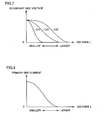
- Fig. 7 is a diagram showing a relation between a distance between power receiving apparatus 110 and power transmitting unit 220 and a secondary voltage (voltage received by electrically powered vehicle 100).
- the secondary voltage received by electrically powered vehicle 100 changes with distance L between power transmitting unit 220 of power transmitting apparatus 200 and power receiving apparatus 110 of electrically powered vehicle 100 as shown in Fig. 7 , in contrast to the primary voltage that is constant as shown in Fig. 6 .
- the relation between the primary voltage and the secondary voltage as shown in Figs. 6 and 7 which is obtained using primary self-resonant coil 224 of power transmitting unit 220, is measured through experiments or the like in advance, plotted on a map or the like, and stored. Based on the detected value of voltage VH representing the secondary voltage, reference can be made to this map to detect the distance between power transmitting unit 220 and power receiving apparatus 110.
- Information about primary self-resonant coil 224 is included in the electric power information transmitted from power transmitter ECU 270 to electrically powered vehicle 100 via communication unit 240 as described above.
- the secondary voltage received by electrically powered vehicle 100 varies as the diameter of the secondary self-resonant coil increases like C 10, C20 and C30 for example in Fig. 7 .
- the diameter of the secondary self-resonant coil corresponding to C10 is the smallest one and that corresponding to C30 is the largest one.
- the diameter of the secondary self-resonant coil is larger, a longer distance can be detected while the precision is lower for shorter distances.
- the distance that can be detected, or detectable distance is shorter while the precision for shorter distances is higher.
- a plurality of secondary self-resonant coils with respective diameters different from each other may be provided and a switch can be made between these coils so that the distance can be precisely detected including distances from longer ones to shorter ones.
- the primary current (current output from power transmitting apparatus 200) changes with distance L between power transmitting unit 220 and power receiving apparatus 110 as shown in Fig. 8 . Therefore, this relation may be used to detect the distance between power transmitting unit 220 and power receiving apparatus 110 based on the detected value of the current output from power transmitting apparatus 200.
- a plurality of secondary self-resonant coils with different diameters is provided and a switch is made between these coils.
- a switch may be made between a plurality of secondary self-resonant coils with different features other than the coil diameter (including for example the shape of the coil and the gap in the vertical direction between the secondary self-resonant coil and the primary self-resonant coil).
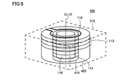
- Fig. 9 shows an external view of a power receiving unit 500 for illustrating general arrangement of secondary self-resonant coils 112, 113 and secondary coil 114 included in power receiving apparatus 110 in the first embodiment.
- power receiving unit 500 includes secondary self-resonant coils 112, 113, secondary coil 114, capacitor 116, bobbins 410, 420, and a coil case 510.
- Bobbins 410, 420 are cylindrical insulators having respective diameters different from each other.
- the diameter of bobbin 410 is smaller than that of bobbin 420, and they are arranged concentrically in coil case 510.
- Secondary self-resonant coils 112, 113 have respective resonance frequencies identical to each other. Secondary self-resonant coils 112, 113 are wound around and accordingly mounted on bobbins 410, 420, respectively. Because respective resonance frequencies of the secondary self-resonant coils are identical to each other, electromagnetic resonance can be caused using any of the secondary self-resonant coils, without changing primary self-resonant coil 224 of power transmitting unit 220. Respective resonance frequencies of the secondary self-resonant coils may not necessarily be exactly identical, and may be slightly different from each other as long as electromagnetic resonance with the power transmitting unit is possible.
- Capacitor 116 is provided within bobbin 410 having the minimum diameter.
- One capacitor 116 is provided per power receiving unit 500, and provided commonly to secondary self-resonant coils 112, 113.
- Switch 120 ( Fig. 4 ) makes a switch to connect the capacitor to the two ends of secondary self-resonant coil 112 or secondary self-resonant coil 113 to thus configure an LC resonance circuit.
- Secondary coil 114 is provided coaxially with minimum-diameter bobbin 410. Secondary coil 114 is provided commonly to secondary self-resonant coils 112, 113. The two ends of the secondary coil are drawn to the outside of coil case 510 and connected to rectifier 140 ( Fig. 4 ).
- Coil case 510 is box-shaped, for example, and houses secondary self-resonant coils 112, 113, secondary coil 114, capacitor 116, and bobbins 410, 420.
- an electromagnetic shield (not shown) is provided on the faces of coil case 510 except for the one thereof opposite to power transmitting unit 220.
- the electromagnetic shield is a low-impedance material, and copper foil for example is used for the shield.
- the shape of coil case 510 is not limited to the rectangular parallelepiped as shown in Fig. 9 as long as the coil case can house secondary self-resonant coils 112, 113, secondary coil 114, capacitor 116, and bobbins 410, 420.
- Other examples of the shape of coil case 510 include cylindrical shape, tubular shape having a polygonal cross section, and the like.
- Fig. 10 is a cross section perpendicular to a central axis CL10 of power receiving unit 500 shown in Fig. 9 .
- one end of secondary self-resonant coil 112 and one end of secondary self-resonant coil 113 are both connected to one end T20 of capacitor 116. Respective other ends of secondary self-resonant coils 112, 113 are connected to connection terminals T 1 and T2 of switch 120, respectively.
- connection terminal T10 of switch 120 The other end of capacitor 116 is connected to connection terminal T10 of switch 120.
- Switch 120 makes a switch so that connection terminal T10 is connected to connection terminal T 1 or T2.
- a positional displacement (distance) between the primary self-resonant coil on the electric power transmitter side and the secondary self-resonant coil on the electric power receiver side influences the transmission efficiency. Specifically, as the distance between the primary self-resonant coil and the secondary self-resonant coil is shorter, the transmission efficiency is higher.
- a resonator on the electric power transmitter (ground) side and a self-resonant coil on the electric power receiver (vehicle) side are aligned through parking operation of the vehicle's driver. It is therefore relatively difficult in some cases, depending on the driver, to exactly align respective positions of the transmitter-side resonator and the receiver-side resonator with respect to each other. It is thus required to allow positional displacement to some extent.
- switching control is performed in a manner that secondary self-resonant coils are switched so that a positional displacement (distance) between the primary self-resonant coil and the secondary self-resonant coil is precisely detected and electric power is transferred efficiently based on the detected distance.
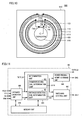
- Fig. 11 shows a diagram of functional blocks involved in switching control for secondary self-resonant coils that is performed by power receiver ECU 185 in the first embodiment.
- the functional blocks shown in Fig. 11 are each implemented through processing by power receiver ECU 185 in a hardware or software manner.
- power receiver ECU 185 includes a distance detection unit 600, a memory unit 610, a determination unit 620, a switching control unit 630, and a power feeding start command unit 640.
- Determination unit 620 includes a distance detecting coil determination unit 621 and a power receiving coil determination unit 622.
- Distance detection unit 600 receives, as inputs, power receiver voltage (secondary voltage) VH provided from voltage sensor 190, signal PRK provided from controller 180 for indicating completion of parking of electrically powered vehicle 100, and signal POS 1 provided from switch 120 for indicating a current switch position. Distance detection unit 600 also receives via communication unit 130, as an input, primary voltage VS of a test signal transmitted from power transmitting apparatus 200 for detecting the distance.
- power receiver voltage secondary voltage
- signal PRK provided from controller 180 for indicating completion of parking of electrically powered vehicle 100
- signal POS 1 provided from switch 120 for indicating a current switch position.
- Distance detection unit 600 also receives via communication unit 130, as an input, primary voltage VS of a test signal transmitted from power transmitting apparatus 200 for detecting the distance.
- Distance detection unit 600 detects from signal PRK the fact that parking of electrically powered vehicle 100 is completed, and then distance detection unit 600 outputs to power transmitting apparatus 200 via communication unit 130, test signal output command TSTFLG1 that is rendered ON. While test signal output command TSTFLG1 is ON, power transmitting apparatus 200 outputs predetermined electric power smaller than the electric power that is supplied during execution of power feeding based on the power feeding start command, as described above. Distance detection unit 600 also outputs to determination unit 620, test signal output command TSTFLG1 so that a test signal for detecting the distance is output.
- Distance detection unit 600 detects distance L between power transmitting unit 220 and power receiving apparatus 110 based on primary voltage VS of the test signal output from power transmitting apparatus 200, secondary voltage VH detected by voltage sensor 190, and switch position POS1 of switch 120. Detected distance L is output to determination unit 620. When detected distance L is finally confirmed, test signal output command TSTFLG1 is rendered OFF.
- distance detection unit 600 detects distance L according to a map stored in advance in storage unit 610 as shown in Fig. 12 .
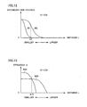
- Fig. 12 is an example of the map stored in memory unit 610 for use in detection of the distance as described above, with respect to a certain primary voltage.
- curve W1 represents a secondary voltage detected by using secondary self-resonant coil 112 having a smaller diameter (hereinafter also referred to as "first coil”)
- curve W2 represents a secondary voltage detected by using secondary self-resonant coil 113 having a larger diameter (hereinafter also referred to as "second coil”).
- distance detection unit 600 first uses the second coil with which a longer distance can be detected and detects distance L. Then, when detected distance L is a distance detectable by using the first coil, switching control unit 630 switches the secondary self-resonant coil, which is used for detecting the distance, to the first coil, and the first coil with higher precision is used to detect distance L again as described later.
- determination unit 620 receives detected distance L and test signal output command TSTFLG1 as inputs from distance detection unit 600.
- distance detecting coil determination unit 621 determines, depending on whether detected distance L is smaller than a predetermined threshold or not, which of respective detected distance values detected by using the first and second coils is to be used.
- distance detecting coil determination unit 621 refers to the map stored in memory unit 610 and shown in Fig. 12 . In the case where distance L detected by the second coil is A1 or more, distance detecting coil determination unit 621 determines that the distance detected by the second coil is to be used and, in the case where this distance L is smaller than A1, determination unit 621 determines that the distance detected by the first coil is to be used. Then, distance detecting coil determination unit 621 outputs to switching control unit 630 coil determination signal CIL 1 representing the result of determination.
- power receiving coil determination unit 622 determines, based on distance L between power transmitting unit 220 and power receiving apparatus 110, which of the first and second coils is to be used for receiving electric power.
- power receiving coil determination unit 622 refers to a map showing a relation between distance L and electric power transmission efficiency ⁇ that is stored in memory unit 610 and shown in Fig. 13 , and selects a coil providing higher transmission efficiency ⁇ for detected distance L.
- curve W10 represents the transmission efficiency of the first coil
- curve W20 represents the transmission efficiency of the second coil.
- the transmission efficiency is relatively higher while the distance over which electric power can be fed is shorter.
- the transmission efficiency is relatively lower while the distance over which electric power can be fed is longer.
- power receiving coil determination unit 622 determines that the first coil is to be selected and, when detected distance L is A10 or more, the determination unit determines that the second coil is to be selected. Then, power receiving coil determination unit 622 outputs coil determination signal CIL10 representing the result of determination to switching control unit 630 and power feeding start command unit 640.
- switching control unit 630 when the distance is to be detected, switching control unit 630 outputs coil switch command SEL1 to switch 120, based on coil determination signal CIL1 that is input from determination unit 620. When the electric power is to be received, switching control unit 630 outputs coil switch command SEL1 to switch 120, based on coil determination signal CIL10 that is input from determination unit 620.
- switch 120 switches the coil used for detecting the distance and switches the coil used for receiving electric power.
- power feeding start command unit 640 receives coil determination signal CIL10 representing the coil used for receiving electric power, from determination unit 620 as an input.
- coil determination signal CIL 10 is set
- power feeding start command unit 640 outputs power feeding start signal CHG to power transmitting apparatus 200 via communication unit 130.
- the threshold based on which the determination as to switching of coils is made for detecting the distance may be set to the same value.
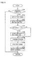
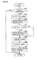
- Figs. 14 and 15 each show a flowchart for illustrating details of a coil switching control process followed by power receiver ECU 185.
- a program stored in advance in power receiver ECU 185 is called from a main routine and executed in predetermined cycles.
- dedicated hardware electronic circuit may be configured to execute the process.
- step 700 determines in step (hereinafter step is abbreviated as S) 700 whether or not parking of electrically powered vehicle 100 is completed, based on signal PRK representing the fact that parking of electrically powered vehicle 100 is completed.
- power receiver ECU 185 selects the second coil with which a longer distance can be detected, and detects distance L between power receiving apparatus 110 and power transmitting unit 220 ( Fig. 1 ).
- power receiver ECU 185 refers to the map stored in memory unit 610 and shown in Fig. 12 , and determines whether or not detected distance L is smaller than A1.
- power receiver ECU 185 uses switch 120 to switch the coil to the first coil with which shorter distances are detected with higher precision, and detects the distance again (S740).
- power receiver ECU 185 confirms distance L detected by means of the first coil as distance L between power receiving apparatus 110 and power transmitting unit 220 ( Fig. 1 ). The process then proceeds to S760 in which the test signal output command is made OFF.
- power receiver ECU 185 After this, power receiver ECU 185 outputs power feeding start command CHG to power transmitting apparatus 200 ( Fig. 1 ), so that electric power feeding by means of the currently selected first coil is started (S770).
- step S740 is skipped and the process proceeds to S750.
- distance L detected by means of the second coil is confirmed as distance L between power receiving apparatus 110 and power transmitting unit 220 (S750).
- power receiver ECU 185 renders test signal output command TSTFLG1 OFF (S760), and outputs power feeding start command CHG to power transmitting apparatus 200 ( Fig. 1 ), so that electric power feeding by means of the selected second coil is started (S770).
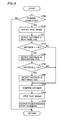
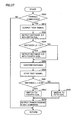
- a threshold used for determining a coil to be used in detecting the distance (threshold A1 in Fig. 12 ) and a threshold used for determining a coil to be used in receiving electric power (threshold A10 in Fig. 13 ) are different from each other.
- Fig. 15 corresponds to the flowchart in Fig. 14 to which S761, S765 and S766 are added. The description of the same step as that of Fig. 14 will not be repeated.
- power receiver ECU 185 proceeds to S761 to determine whether or not confirmed distance L is smaller than A10.
- power receiver ECU 185 switches the coil to be used for receiving electric power to the first coil with relatively higher transmission efficiency ⁇ for shorter distances. Then, in S770, power receiver ECU 185 outputs power feeding start command CHG to power transmitting apparatus 200 ( Fig. 1 ).
- power receiver ECU 185 switches the coil to be used for receiving electric power to the second coil with relatively higher transmission efficiency ⁇ for longer distances. Then, in S770, power receiver ECU 185 outputs power feeding start command CHG to power transmitting apparatus 200 ( Fig: 1 ).
- the vehicle power feeding system has power receiving apparatus 110 including a plurality of secondary self-resonant coils 112, 113.
- a switch is made between these secondary self-resonant coils 112, 113 for detecting the distance between power receiving apparatus 110 and power transmitting unit 220.
- a power-receiving secondary self-resonant coil that has higher transmission efficiency can be selected for feeding electric power. Accordingly, the distance between power receiving apparatus 110 and power transmitting unit 220 can be detected precisely, including distances from longer distances to shorter distances, and the transmission efficiency in transmitting electric power by means of the resonance method can be improved.
- Fig. 16 is a diagram corresponding to Fig. 10 in the first embodiment and showing details of connections in a power receiving unit 500.
- a secondary self-resonant coil 115 (hereinafter also referred to as "third coil") having a larger diameter than secondary self-resonant coil 113 (second coil) in Fig. 10 , and a bobbin 430 for mounting the third coil thereon are further provided, and all of the first, second and third coils are housed in one coil case 510. Accordingly, switch 120 for making a switch between two contacts is replaced with a switch 120# capable of making a switch between three contacts. The description of the same feature as Fig. 10 will not be repeated.
- bobbin 430 is provided concentrically with bobbins 410, 420. Secondary self-resonant coil 115 is wound around and thus mounted on bobbin 430.
- connection terminal T10# of switch 120# The other end of the capacitor is connected to a connection terminal T10# of switch 120#.
- Switch 120# makes a switch so that connection terminal T10# is connected to one of connection terminals T1#, T2#, T3#.
- Figs. 17 and 18 correspond respectively to Figs. 12 and 13 in the first embodiment, and illustrate a relation between a distance between power receiving apparatus 110 and power transmitting unit 220 and secondary voltage VH, and a relation between the distance therebetween and transmission efficiency ⁇ , respectively.
- curves W3 and W30 for the third coil are additionally shown.
- curve W3 corresponds to the third coil.
- the third coil is used to detect the distance.
- distance L is smaller than B1 and is A1 or more, the second coil is used to detect the distance.
- curve W30 corresponds to the third coil.
- the third coil is used to receive electric power.
- distance L is smaller than threshold B10 and is A10 or more, the second coil is used to receive electric power.
- Fig. 19 corresponds to Fig. 14 in the first embodiment to which S711 and S712 are added. The description of the same step as Fig. 14 will not be repeated.
- power receiver ECU 185 outputs the test signal output command in S710 and proceeds to S711 in which power receiver ECU 185 first selects the third coil with which the longest distance can be detected, and detects the distance.
- power feeding start command CHG is output to power transmitting apparatus 200 so that power feeding by means of the currently selected third coil is started (S770).
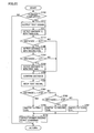
- Fig. 20 shows a flowchart illustrating details of a coil switching control process in the case where a threshold used for determining a coil in detecting the distance and a threshold used for determining a coil in receiving electric power are different (namely A1 ⁇ A10, B1 ⁇ B10).
- Fig. 20 corresponds to Fig. 15 in the first embodiment to which S711, S712, S762, S767 are added. Among these steps, S711 and S712 are similar to those in Fig. 19 . The description of the same step as Figs. 15 and 19 will not be repeated.
- power receiver ECU 185 proceeds to S761 to determine whether or not confirmed distance L is smaller than A10.
- power receiver ECU 185 switches the coil used for receiving electric power to the first coil. The process then proceeds to S770.
- power receiver ECU 185 switches the coil to be used for receiving electric power to the second coil. The process then proceeds to S770.
- power receiver ECU 185 switches the coil to be used for receiving electric power to the third coil. The process then proceeds to S770.
- power receiver ECU 185 outputs power feeding start command CHG to power transmitting apparatus 200.
- the third coil having a larger diameter is added.
- a coil having a diameter between the diameter of the first coil and the diameter of the second coil may be added, or a coil having a smaller diameter than the first coil may be added.
- four or more secondary self-resonant coils may be included.
- a combination of appropriate coil diameters may be selected on the condition that the coil size falls within the range that can be mounted on electrically powered vehicle 100 and the installation cost falls within a tolerable range.
- a desired detectable distance can be ensured while the precision in detecting the distance can be improved for distances including longer distances and shorter distances.
- the coil to be used can be switched to improve the transmission efficiency in feeding electric power.
- Fig. 21 shows a detailed configuration diagram of power transmitting apparatus 200 in the second embodiment.
- Fig. 21 corresponds to Fig. 5 in the first embodiment including power transmitting unit 220 to which a primary self-resonant second coil 225 and a switch 230 are added.
- power transmitting unit 220 to which a primary self-resonant second coil 225 and a switch 230 are added.
- a primary self-resonant second coil 225 and a switch 230 are added.
- primary self-resonant coils 224, 225 have respective resonance frequencies identical to each other and respective diameters different from each other.
- One end of primary self-resonant coil 224 and one end of primary self-resonant coil 225 are connected to each other and respective other ends are connected respectively to connection ends T 1 * and T1 * of switch 230.
- capacitor 280 has one end connected to a connection node of primary self-resonant coils 224, 225 and the other end connected to a connection end T10* of switch 230.
- Switch 230 follows switch command SEL2 of power transmitter ECU 270 to make a switch so that the connection end to which capacitor 280 is connected is connected to the connection end of one of primary self-resonant coils 224, 225. At this time, switch 230 outputs to power transmitter ECU 270 signal POS2 indicating which of the primary self-resonant coils is connected to the capacitor.
- Fig. 22 will be used to illustrate details of connections in power transmitting unit 220.
- Fig. 22 shows a cross section of power transmitting unit 220 like Fig. 10 in the first embodiment.
- the general arrangement and connections of constituent devices in power transmitting unit 220 are similar to the configuration in Figs. 9 and 10 in the first embodiment.
- secondary coil 114 in Fig. 9 corresponds to primary coil 222
- secondary self-resonant coils 112, 113 correspond to primary self-resonant coils 224, 225.
- capacitor 116 corresponds to capacitor 280
- coil case 510 corresponds to coil case 520.
- bobbins 410, 420 correspond to bobbins 440, 450
- switch 120 correspond to switch 230. The description of details of each device will not be repeated.
- one end of primary self-resonant coil 224 and one end of primary self-resonant coil 225 are both connected to one end T20* of capacitor 280. Respective other ends of primary self-resonant coils 224, 225 are connected respectively to connection terminals T1 * and T2* of switch 230.
- connection terminal T10* of switch 230 The other end of capacitor 280 is connected to connection terminal T10* of switch 230.
- Switch 230 makes a switch so that connection terminal T10* is connected to connection terminal T1 or T2* .
- Fig. 23 shows a diagram of functional blocks involved in switching control for primary self-resonant coils that is performed by power transmitter ECU 270 in the present second embodiment. Each functional block shown in Fig. 23 is implemented through processing by power transmitter ECU 270 in a hardware or software manner.
- power transmitter ECU 270 includes a distance detection unit 650, a memory unit 660, a determination unit 670, a switching control unit 680, and a power feeding control unit 690.
- Determination unit 670 includes a distance detecting coil determination unit 671 and a power receiving coil determination unit 672.
- Distance detection unit 650 receives, as inputs, power transmitter voltage (primary voltage) VS from voltage sensor 272 and signal POS2 provided from switch 230 for indicating a current switch position. Via communication unit 240, distance detection unit 650 also receives, as inputs, signal PRK representing completion of parking of electrically powered vehicle 100, and secondary voltage VH in response to a distance detection test signal that is detected by power receiving apparatus 110.
- distance detection unit 650 When distance detection unit 650 detects from signal PRK the fact that parking of electrically powered vehicle 100 is completed, distance detection unit 650 outputs to determination unit 670 and power feeding control unit 690, test signal output command TSTFLG2 that is rendered ON to output a test signal for detecting the distance. While test signal output command TSTFLG2 is ON, power feeding control unit 690 outputs predetermined electric power smaller than the electric power that is supplied during execution of power feeding based on the power feeding start command from the electrically powered vehicle.
- distance detection unit 650 detects distance L2 between power transmitting unit 220 and power receiving apparatus 110, based on secondary voltage VH received from power receiving apparatus 110 and provided in response to the test signal, primary voltage VS detected by voltage sensor 272, and switch position POS2 of switch 230, and outputs detected distance L2 to determination unit 670.
- test signal output command TSTFLG2 is rendered OFF.
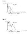
- distance detection unit 650 detects distance L2 following a map as shown in Fig. 24 and stored in advance in memory unit 660.
- Fig. 24 is an example of the map stored in memory unit 660 for use in detection of the distance as described above, with respect to a certain primary voltage.
- curve W5 represents a secondary voltage detected in power receiving apparatus 110 when primary self-resonant coil 224 having a smaller diameter (hereinafter also referred to as "fourth coil”) is used
- curve W6 represents a secondary voltage detected in power receiving apparatus 110 when primary self-resonant coil 225 having a larger diameter (hereinafter also referred to as "fifth coil”) is used.
- distance detection unit 650 first uses the fifth coil with which a longer distance can be detected, transmits electric power, and detects distance L2. Then, when the distance can be detected through power transmission by means of the fourth coil, switching control unit 680 switches the coil to be used for detecting the distance to the fourth coil. Distance detection unit 650 thus detects distance L2 more precisely by transmitting electric power by means of the fourth coil.
- determination unit 670 receives, as inputs, detected distance L2 and test signal output command TSTFLG2 from distance detection unit 650.
- distance detecting coil determination unit 671 determines, depending on whether detected distance L2 is smaller than a predetermined threshold or not, which of the fourth and fifth coils is to be used to detect the distance.
- distance detecting coil determination unit 671 refers to the map stored in memory unit 660 and shown in Fig. 24 . In the case where distance L2 detected by means of the fifth coil is D 1 or more, distance detecting coil determination unit 671 determines that the distance detected by the fifth coil is to be used and, in the case where this distance L2 is smaller than D1, distance detecting coil determination unit 671 determines that the distance detected by means of the fourth coil is to be used. Then, distance detecting coil determination unit 671 outputs to switching control unit 680 coil determination signal CIL2 representing the result of determination.
- power transmitting coil determination unit 672 determines, based on distance L2 between power transmitting unit 220 and power receiving apparatus 110, which of the fourth and fifth coils is to be used for transmitting electric power.
- power transmitting coil determination unit 672 refers to a map showing a relation between distance L2 and electric power transmission efficiency ⁇ as shown in Fig. 25 , and selects a primary self-resonant coil providing higher transmission efficiency ⁇ for detected distance L2.
- curve W50 represents the transmission efficiency of the fourth coil
- curve W60 represents the transmission efficiency of the fifth coil.
- the transmission efficiency is relatively higher while the distance over which electric power can be fed is shorter.
- the transmission efficiency is relatively lower while the distance over which electric power can be fed is longer.
- power transmitting coil determination unit 672 determines that the fourth coil is to be selected and, when detected distance L2 is D10 or more, the determination unit determines that the fifth coil is to be selected. Then, power transmitting coil determination unit 672 outputs coil determination signal CIL20 representing the result of determination to switching control unit 680 and power feeding control unit 690.
- switching control unit 680 when the distance is to be detected, switching control unit 680 outputs coil switch command SEL2 to switch 230, based on coil determination signal CIL2 that is input from determination unit 670.
- switching control unit 680 When electric power is to be transmitted, switching control unit 680 outputs coil switch command SEL2 to switch 230, based on coil determination signal CIL20 that is input from determination unit 670.
- switch 230 switches the coil used for detecting the distance and the coil used for transmitting electric power.
- power feeding control unit 690 In the case where power feeding control unit 690 receives input of test signal output command TSTFLG2 from distance detection unit 650, power feeding control unit 690 controls high-frequency electric power driver 260 so that electric power is fed for detecting the distance. In the case where input of power feeding start command CHG is received from electrically powered vehicle 100, high-frequency electric power driver 260 is controlled so that practical and regular electric power feeding is performed.
- the threshold used for determination as to switching of the coil for use in detecting the distance may be set to the same value.
- the determination as to the coil to be used for transmitting electric power that is made by determination unit 670 is skipped, and the coil finally used for detecting the distance is used as a coil for transmitting electric power, and power feeding is started.
- Figs. 26 and 27 each show a flowchart for illustrating details of a coil switching control process followed by power transmitter ECU 270.
- a program stored in advance in power transmitter ECU 270 is called from a main routine and executed in predetermined cycles.
- dedicated hardware electronic circuit may be configured to execute the process.
- power transmitter ECU 270 determines in step S800 whether or not parking of electrically powered vehicle 100 ( Fig. 1 ) is completed, based on signal PRK that represents the fact that parking of electrically powered vehicle 100 ( Fig. 1 ) is completed and is received from electrically powered vehicle 100 ( Fig. 1 ) via communication unit 240.
- power transmitter ECU 270 uses distance detection unit 650 to select the fifth coil and detect distance L2 between power receiving apparatus 110 ( Fig. 1 ) and power transmitting unit 220.
- power transmitter ECU 270 refers to the map stored in memory unit 660 and as shown in Fig. 24 , based on detected distance L2, and determines whether or not detected distance L2 is smaller than D1.
- power transmitter ECU 270 switches the coil to the fourth coil, and detects the distance again (S840).
- power transmitter ECU 270 confirms distance L2 detected by means of the fourth coil as distance L2 between power receiving apparatus 110 ( Fig. 1 ) and power transmitting unit 220 and, in S860, renders test signal output command TSTFLG2 OFF.
- power feeding control unit 690 uses the currently selected fourth coil and starts feeding electric power (S870).
- step S840 is skipped and the process proceeds to S850.
- distance L2 detected by means of the fifth coil is confirmed as distance L2 between power receiving apparatus 110 ( Fig. 1 ) and power transmitting unit 220.
- test signal output command TSTFLG2 is rendered OFF in S860, and the currently selected fifth coil is used to start feeding electric power (S870).
- a threshold for determining a coil to be used in detecting the distance (threshold D 1 in Fig. 24 ) and a threshold for determining a coil to be used in receiving electric power (threshold D10 in Fig. 25 ) are different from each other.
- Fig. 27 corresponds to the flowchart in Fig. 26 to which S861, S865 and S866 are added. The description of the same step as that of Fig. 26 will not be repeated.
- power transmitter ECU 270 proceeds to S861 to determine whether or not confirmed distance L2 is smaller than D10.
- power transmitter ECU 270 switches the coil to be used for transmitting electric power to the fourth coil. Then, in S870, power transmitter ECU 270 starts feeding electric power.
- power transmitter ECU 270 switches the coil to be used for transmitting electric power to the fifth coil. Then, in S870, power transmitter ECU 270 starts feeding electric power.
- power transmitting unit 220 includes a plurality of primary self-resonant coils 224, 225.
- the distance between power receiving apparatus 110 and power transmitting unit 220 is detected. Based on the detected distance, a primary self-resonant coil for transmitting electric power is selected to feed the electric power. Accordingly, the distance between power receiving apparatus 110 and power transmitting unit 220 can be detected precisely, and the transmission efficiency in transmitting electric power by means of the resonance method can be improved.
- the second embodiment is also applicable to the case where three or more primary self-resonant coils are included like the modification of the first embodiment.
- the system may be configured so that both of the diameter of the primary self-resonant coil and the diameter of the secondary self-resonant coil can be switched, like a combination of the first and second embodiments.
- the vehicle's driver may select one of the diameter of the primary self-resonant coil and the diameter of the secondary self-resonant coil that is to be preferentially switched, or the coil to be switched may be automatically selected depending on other conditions (the specification or the like of the coil, for example).
- both of respective diameters of the primary and secondary self-resonant coils may be switched and a combination of respective diameters of the primary and secondary self-resonant coils may be changed.
- primary coils 220, 320 and secondary coils 114, 350 in the present embodiments are examples of “electromagnetic coil” of the present invention.
- power receiver ECU 185 and power transmitter ECU 270 are examples of “controller” of the present invention.
- inverters 164, 166 and motor generators 172, 174 are examples of “electrical drive apparatus" of the present invention.
Applications Claiming Priority (1)
| Application Number | Priority Date | Filing Date | Title |
|---|---|---|---|
| PCT/JP2009/062104 WO2011001524A1 (fr) | 2009-07-02 | 2009-07-02 | Unité de bobine, dispositif de réception d'énergie sans contact, dispositif d'alimentation d'énergie sans contact, système d'alimentation d'énergie sans contact et véhicule |
Publications (1)
| Publication Number | Publication Date |
|---|---|
| EP2450920A1 true EP2450920A1 (fr) | 2012-05-09 |
Family
ID=43410622
Family Applications (1)
| Application Number | Title | Priority Date | Filing Date |
|---|---|---|---|
| EP09846817A Withdrawn EP2450920A1 (fr) | 2009-07-02 | 2009-07-02 | Unité de bobine, dispositif de réception d'énergie sans contact, dispositif d'alimentation d'énergie sans contact, système d'alimentation d'énergie sans contact et véhicule |
Country Status (5)
| Country | Link |
|---|---|
| US (1) | US20120098330A1 (fr) |
| EP (1) | EP2450920A1 (fr) |
| JP (1) | JP4947241B2 (fr) |
| CN (1) | CN102449711A (fr) |
| WO (1) | WO2011001524A1 (fr) |
Cited By (1)
| Publication number | Priority date | Publication date | Assignee | Title |
|---|---|---|---|---|
| US10086715B2 (en) | 2016-04-05 | 2018-10-02 | Hyundai America Technical Center, Inc. | EV wireless charging adjustable flux angle charger |
Families Citing this family (42)
| Publication number | Priority date | Publication date | Assignee | Title |
|---|---|---|---|---|
| JP2011142559A (ja) * | 2010-01-08 | 2011-07-21 | Sony Corp | 給電装置、受電装置、およびワイヤレス給電システム |
| KR101391487B1 (ko) * | 2010-04-30 | 2014-05-07 | 후지쯔 가부시끼가이샤 | 수전 장치 및 수전 방법 |
| US9054542B2 (en) * | 2010-06-10 | 2015-06-09 | Access Business Group International Llc | Coil configurations for inductive power transfer |
| US20120025623A1 (en) * | 2010-07-28 | 2012-02-02 | Qualcomm Incorporated | Multi-loop wireless power receive coil |
| JP5677875B2 (ja) | 2011-03-16 | 2015-02-25 | 日立マクセル株式会社 | 非接触電力伝送システム |
| JPWO2013005415A1 (ja) * | 2011-07-04 | 2015-02-23 | 日本電気株式会社 | 無線電力伝送装置および方法、ならびに、中継器 |
| CN103718427B (zh) * | 2011-07-28 | 2017-04-12 | 本田技研工业株式会社 | 无线送电方法 |
| JP5838685B2 (ja) * | 2011-09-21 | 2016-01-06 | 日本電気株式会社 | 無線空間給電システム |
| JPWO2013042229A1 (ja) * | 2011-09-21 | 2015-03-26 | トヨタ自動車株式会社 | 非接触送電装置、非接触受電装置および非接触送受電システム |
| EP2763148B1 (fr) * | 2011-09-28 | 2019-07-31 | Toyota Jidosha Kabushiki Kaisha | Dispositif de réception d'énergie, dispositif de transmission d'énergie et système de transmission d'énergie |
| US9673664B2 (en) * | 2011-10-27 | 2017-06-06 | Toyota Jidosha Kabushiki Kaisha | Wireless power reception apparatus, wireless power transmission apparatus, and wireless power transmission and reception system |
| JP5915667B2 (ja) * | 2012-01-31 | 2016-05-11 | 富士通株式会社 | 電力伝送装置、電力伝送システム、及び電力伝送方法 |
| US9531441B2 (en) | 2012-02-21 | 2016-12-27 | Lg Innotek Co., Ltd. | Wireless power receiver and method of managing power thereof |
| KR101697418B1 (ko) | 2012-05-09 | 2017-01-17 | 도요타지도샤가부시키가이샤 | 차량 |
| JP5747863B2 (ja) * | 2012-05-11 | 2015-07-15 | トヨタ自動車株式会社 | 車両、受電装置、送電装置および非接触給電システム |
| JP2013240246A (ja) * | 2012-05-17 | 2013-11-28 | Toshiba Corp | 無線給電中継装置 |
| US20130328387A1 (en) * | 2012-06-08 | 2013-12-12 | Sagar Venkateswaran | Supercapacitor vehicle and roadway system |
| CN102820714B (zh) * | 2012-09-03 | 2015-06-10 | 重庆市电力公司电力科学研究院 | 一种无线充电装置 |
| CN102891538A (zh) * | 2012-09-20 | 2013-01-23 | 中国科学院自动化研究所 | 巡线机器人无线充电系统 |
| US9352661B2 (en) | 2013-04-29 | 2016-05-31 | Qualcomm Incorporated | Induction power transfer system with coupling and reactance selection |
| KR102125917B1 (ko) | 2013-08-07 | 2020-07-08 | 엘지이노텍 주식회사 | 무선전력 송신장치 |
| JP5842901B2 (ja) * | 2013-12-05 | 2016-01-13 | トヨタ自動車株式会社 | 非接触電力伝送システム |
| WO2015121977A1 (fr) * | 2014-02-14 | 2015-08-20 | 日産自動車株式会社 | Appareil d'alimentation électrique sans contact |
| JP6329386B2 (ja) | 2014-02-21 | 2018-05-23 | ルネサスエレクトロニクス株式会社 | 非接触給電方法及び非接触給電システム |
| CN106133854B (zh) * | 2014-03-26 | 2019-08-27 | 苹果公司 | 用于感应式充电系统的温度管理 |
| KR20170041706A (ko) | 2014-06-26 | 2017-04-17 | 솔라스 파워 인크. | 무선 전계 송전 시스템, 이를 위한 송신기 및 수신기, 및 무선 송전 방법 |
| CN107005092B (zh) | 2014-09-05 | 2020-03-10 | 索雷斯能源公司 | 无线电场电力传递系统、方法及其发射器和接收器 |
| JP5965975B2 (ja) * | 2014-12-02 | 2016-08-10 | 株式会社ダイヘン | 非接触給電システム、送電装置、給電方法および送電方法 |
| JP6106151B2 (ja) * | 2014-12-16 | 2017-03-29 | 株式会社ダイヘン | 非接触給電システム、送電装置、および、位置ずれ検出方法 |
| DE102014226348A1 (de) * | 2014-12-18 | 2016-06-23 | Robert Bosch Gmbh | Ladevorrichtung zum Laden eines elektrischen Energiespeichers |
| US9944190B2 (en) * | 2015-03-07 | 2018-04-17 | Hyundai Motor Company | Interoperable EV wireless charging system based on air gap between primary and secondary coils |
| CN106300486B (zh) * | 2015-06-11 | 2019-03-08 | 联想(北京)有限公司 | 充电方法以及充电装置 |
| JP6314934B2 (ja) * | 2015-08-07 | 2018-04-25 | トヨタ自動車株式会社 | 車両 |
| KR102048652B1 (ko) * | 2016-05-23 | 2019-11-25 | 닛산 지도우샤 가부시키가이샤 | 비접촉 급전 시스템의 코일 위치 검출 방법 및 비접촉 급전 시스템 |
| CN110462967B (zh) * | 2017-01-23 | 2021-07-30 | 耐克创新有限合伙公司 | 具有多线圈扫描的无线充电系统 |
| WO2018144806A1 (fr) * | 2017-02-03 | 2018-08-09 | AMI Research & Development, LLC | Recharge de véhicule électrique par antennes cadres rf pour éviter un besoin d'alignement précis avec un équipement de recharge sans fil |
| KR102605850B1 (ko) * | 2017-02-06 | 2023-11-24 | 주식회사 위츠 | 무선전력 송신장치 및 무선전력 송신장치 제어 방법 |
| EP3631946A4 (fr) | 2017-05-30 | 2020-12-09 | Wireless Advanced Vehicle Electrification Inc. | Charge sans fil à plages d'accueil multiples à alimentation unique |
| JP6798428B2 (ja) * | 2017-06-08 | 2020-12-09 | トヨタ自動車株式会社 | 送電装置および受電装置 |
| US11462943B2 (en) | 2018-01-30 | 2022-10-04 | Wireless Advanced Vehicle Electrification, Llc | DC link charging of capacitor in a wireless power transfer pad |
| US10892652B2 (en) * | 2018-12-12 | 2021-01-12 | Semtech Corporation | Adaptive ping method for wireless charging system with wide charge distance |
| JP2021057960A (ja) * | 2019-09-27 | 2021-04-08 | オムロン株式会社 | 非接触給電装置 |
Family Cites Families (18)
| Publication number | Priority date | Publication date | Assignee | Title |
|---|---|---|---|---|
| JPH0666198B2 (ja) * | 1984-03-19 | 1994-08-24 | 松下電器産業株式会社 | 小型フライバックトランス |
| JPH0965502A (ja) * | 1995-08-23 | 1997-03-07 | Sumitomo Electric Ind Ltd | 誘導式給電・集電装置 |
| JP3169817B2 (ja) * | 1996-01-30 | 2001-05-28 | 三菱電機株式会社 | 磁気結合信号伝送装置 |
| JP2003150233A (ja) * | 2001-11-12 | 2003-05-23 | Hitachi Ltd | プラントの性能劣化状態評価方法と性能劣化状態評価装置 |
| JP3906708B2 (ja) * | 2002-02-25 | 2007-04-18 | 松下電工株式会社 | 非接触電力伝達装置 |
| JP2004072832A (ja) * | 2002-08-02 | 2004-03-04 | Hitachi Kiden Kogyo Ltd | 非接触給電方法 |
| WO2005106901A2 (fr) * | 2004-05-04 | 2005-11-10 | Philips Intellectual Property & Standards Gmbh | Dispositif d'alimentation sans fil, charge d'excitation, systeme sans fil et procede de transfert d'energie sans fil |
| KR101254550B1 (ko) * | 2005-04-22 | 2013-04-19 | 가부시키가이샤 다이후쿠 | 무접촉 급전 설비의 2차측 수전 회로 장치 |
| AU2006269374C1 (en) | 2005-07-12 | 2010-03-25 | Massachusetts Institute Of Technology | Wireless non-radiative energy transfer |
| JP4453741B2 (ja) * | 2007-10-25 | 2010-04-21 | トヨタ自動車株式会社 | 電動車両および車両用給電装置 |
| US8729734B2 (en) * | 2007-11-16 | 2014-05-20 | Qualcomm Incorporated | Wireless power bridge |
| JP2009213550A (ja) * | 2008-03-07 | 2009-09-24 | Jms Co Ltd | 熱交換器及びそれを備えた人工肺装置 |
| RU2010141703A (ru) * | 2008-03-13 | 2012-04-20 | Эксесс Бизнес Груп Интернейшнл Ллс (Us) | Индуктивная система питания с первичной обмоткой с множеством катушек |
| CN101383531A (zh) * | 2008-07-01 | 2009-03-11 | 陈远鸿 | 无线电源远距离输电装置 |
| JP4911148B2 (ja) * | 2008-09-02 | 2012-04-04 | ソニー株式会社 | 非接触給電装置 |
| JP4962621B2 (ja) * | 2008-10-09 | 2012-06-27 | トヨタ自動車株式会社 | 非接触電力伝達装置および非接触電力伝達装置を備える車両 |
| US20100201309A1 (en) * | 2009-02-10 | 2010-08-12 | Meek Ivan C | Systems and methods for coupling a vehicle to an external grid and/or network |
| JP5365306B2 (ja) * | 2009-03-31 | 2013-12-11 | 富士通株式会社 | 無線電力供給システム |
-
2009
- 2009-07-02 US US13/143,735 patent/US20120098330A1/en not_active Abandoned
- 2009-07-02 EP EP09846817A patent/EP2450920A1/fr not_active Withdrawn
- 2009-07-02 CN CN2009801596207A patent/CN102449711A/zh active Pending
- 2009-07-02 WO PCT/JP2009/062104 patent/WO2011001524A1/fr active Application Filing
- 2009-07-02 JP JP2011520714A patent/JP4947241B2/ja not_active Expired - Fee Related
Non-Patent Citations (1)
| Title |
|---|
| See references of WO2011001524A1 * |
Cited By (1)
| Publication number | Priority date | Publication date | Assignee | Title |
|---|---|---|---|---|
| US10086715B2 (en) | 2016-04-05 | 2018-10-02 | Hyundai America Technical Center, Inc. | EV wireless charging adjustable flux angle charger |
Also Published As
| Publication number | Publication date |
|---|---|
| US20120098330A1 (en) | 2012-04-26 |
| JP4947241B2 (ja) | 2012-06-06 |
| JPWO2011001524A1 (ja) | 2012-12-10 |
| CN102449711A (zh) | 2012-05-09 |
| WO2011001524A1 (fr) | 2011-01-06 |
Similar Documents
| Publication | Publication Date | Title |
|---|---|---|
| EP2450920A1 (fr) | Unité de bobine, dispositif de réception d'énergie sans contact, dispositif d'alimentation d'énergie sans contact, système d'alimentation d'énergie sans contact et véhicule | |
| EP2528193B1 (fr) | Appareil de reception de courant électrique sans contact, appareil de transmission de courant électrique sans contact, système d'alimentation électrique sans contact, et véhicule | |
| EP2345553B1 (fr) | Dispositif de transmission d énergie sans contact et véhicule équipé de celui-ci | |
| JP5016069B2 (ja) | 電力伝送システムおよび車両用給電装置 | |
| JP5347708B2 (ja) | コイルユニット、非接触電力伝送装置、非接触給電システムおよび車両 | |
| JP5287863B2 (ja) | 非接触受電装置およびそれを備える車両 | |
| JP5263391B2 (ja) | 非接触受電装置およびそれを備える車両 | |
| JP5768878B2 (ja) | 車両 | |
| WO2010119577A1 (fr) | Équipement d'alimentation électrique sans contact, récepteur de puissance sans contact et système d'alimentation électrique sans contact | |
| JP2011167036A (ja) | 車両用給電装置および受電装置 | |
| JP5474470B2 (ja) | 非接触受電装置およびそれを備える電動車両 | |
| JP5287115B2 (ja) | 車両の受電制御装置およびそれを備える車両 | |
| RU2461946C1 (ru) | Устройство бесконтактного получения энергии и транспортное средство, содержащее такое устройство | |
| JP5920185B2 (ja) | 非接触受電装置 | |
| JP2015027224A (ja) | 非接触受電装置 | |
| JP2015035872A (ja) | 非接触受電装置 | |
| JPWO2013042229A1 (ja) | 非接触送電装置、非接触受電装置および非接触送受電システム |
Legal Events
| Date | Code | Title | Description |
|---|---|---|---|
| PUAI | Public reference made under article 153(3) epc to a published international application that has entered the european phase |
Free format text: ORIGINAL CODE: 0009012 |
|
| 17P | Request for examination filed |
Effective date: 20110811 |
|
| AK | Designated contracting states |
Kind code of ref document: A1 Designated state(s): AT BE BG CH CY CZ DE DK EE ES FI FR GB GR HR HU IE IS IT LI LT LU LV MC MK MT NL NO PL PT RO SE SI SK SM TR |
|
| STAA | Information on the status of an ep patent application or granted ep patent |
Free format text: STATUS: THE APPLICATION HAS BEEN WITHDRAWN |
|
| DAX | Request for extension of the european patent (deleted) | ||
| 18W | Application withdrawn |
Effective date: 20120919 |