WO2010143585A1 - カーボンナノチューブおよびその製造方法 - Google Patents
カーボンナノチューブおよびその製造方法 Download PDFInfo
- Publication number
- WO2010143585A1 WO2010143585A1 PCT/JP2010/059492 JP2010059492W WO2010143585A1 WO 2010143585 A1 WO2010143585 A1 WO 2010143585A1 JP 2010059492 W JP2010059492 W JP 2010059492W WO 2010143585 A1 WO2010143585 A1 WO 2010143585A1
- Authority
- WO
- WIPO (PCT)
- Prior art keywords
- anode
- carbon nanotubes
- carbon
- soot
- producing
- Prior art date
Links
Images


Classifications
-
- B—PERFORMING OPERATIONS; TRANSPORTING
- B01—PHYSICAL OR CHEMICAL PROCESSES OR APPARATUS IN GENERAL
- B01J—CHEMICAL OR PHYSICAL PROCESSES, e.g. CATALYSIS OR COLLOID CHEMISTRY; THEIR RELEVANT APPARATUS
- B01J19/00—Chemical, physical or physico-chemical processes in general; Their relevant apparatus
- B01J19/08—Processes employing the direct application of electric or wave energy, or particle radiation; Apparatus therefor
- B01J19/087—Processes employing the direct application of electric or wave energy, or particle radiation; Apparatus therefor employing electric or magnetic energy
- B01J19/088—Processes employing the direct application of electric or wave energy, or particle radiation; Apparatus therefor employing electric or magnetic energy giving rise to electric discharges
-
- B—PERFORMING OPERATIONS; TRANSPORTING
- B82—NANOTECHNOLOGY
- B82Y—SPECIFIC USES OR APPLICATIONS OF NANOSTRUCTURES; MEASUREMENT OR ANALYSIS OF NANOSTRUCTURES; MANUFACTURE OR TREATMENT OF NANOSTRUCTURES
- B82Y30/00—Nanotechnology for materials or surface science, e.g. nanocomposites
-
- B—PERFORMING OPERATIONS; TRANSPORTING
- B82—NANOTECHNOLOGY
- B82Y—SPECIFIC USES OR APPLICATIONS OF NANOSTRUCTURES; MEASUREMENT OR ANALYSIS OF NANOSTRUCTURES; MANUFACTURE OR TREATMENT OF NANOSTRUCTURES
- B82Y40/00—Manufacture or treatment of nanostructures
-
- C—CHEMISTRY; METALLURGY
- C01—INORGANIC CHEMISTRY
- C01B—NON-METALLIC ELEMENTS; COMPOUNDS THEREOF; METALLOIDS OR COMPOUNDS THEREOF NOT COVERED BY SUBCLASS C01C
- C01B32/00—Carbon; Compounds thereof
- C01B32/15—Nano-sized carbon materials
- C01B32/158—Carbon nanotubes
- C01B32/16—Preparation
-
- C—CHEMISTRY; METALLURGY
- C01—INORGANIC CHEMISTRY
- C01B—NON-METALLIC ELEMENTS; COMPOUNDS THEREOF; METALLOIDS OR COMPOUNDS THEREOF NOT COVERED BY SUBCLASS C01C
- C01B32/00—Carbon; Compounds thereof
- C01B32/15—Nano-sized carbon materials
- C01B32/158—Carbon nanotubes
- C01B32/16—Preparation
- C01B32/162—Preparation characterised by catalysts
-
- C—CHEMISTRY; METALLURGY
- C01—INORGANIC CHEMISTRY
- C01B—NON-METALLIC ELEMENTS; COMPOUNDS THEREOF; METALLOIDS OR COMPOUNDS THEREOF NOT COVERED BY SUBCLASS C01C
- C01B32/00—Carbon; Compounds thereof
- C01B32/15—Nano-sized carbon materials
- C01B32/158—Carbon nanotubes
- C01B32/168—After-treatment
- C01B32/17—Purification
-
- B—PERFORMING OPERATIONS; TRANSPORTING
- B01—PHYSICAL OR CHEMICAL PROCESSES OR APPARATUS IN GENERAL
- B01J—CHEMICAL OR PHYSICAL PROCESSES, e.g. CATALYSIS OR COLLOID CHEMISTRY; THEIR RELEVANT APPARATUS
- B01J2219/00—Chemical, physical or physico-chemical processes in general; Their relevant apparatus
- B01J2219/08—Processes employing the direct application of electric or wave energy, or particle radiation; Apparatus therefor
- B01J2219/0803—Processes employing the direct application of electric or wave energy, or particle radiation; Apparatus therefor employing electric or magnetic energy
- B01J2219/0805—Processes employing the direct application of electric or wave energy, or particle radiation; Apparatus therefor employing electric or magnetic energy giving rise to electric discharges
- B01J2219/0807—Processes employing the direct application of electric or wave energy, or particle radiation; Apparatus therefor employing electric or magnetic energy giving rise to electric discharges involving electrodes
- B01J2219/0809—Processes employing the direct application of electric or wave energy, or particle radiation; Apparatus therefor employing electric or magnetic energy giving rise to electric discharges involving electrodes employing two or more electrodes
-
- B—PERFORMING OPERATIONS; TRANSPORTING
- B01—PHYSICAL OR CHEMICAL PROCESSES OR APPARATUS IN GENERAL
- B01J—CHEMICAL OR PHYSICAL PROCESSES, e.g. CATALYSIS OR COLLOID CHEMISTRY; THEIR RELEVANT APPARATUS
- B01J2219/00—Chemical, physical or physico-chemical processes in general; Their relevant apparatus
- B01J2219/08—Processes employing the direct application of electric or wave energy, or particle radiation; Apparatus therefor
- B01J2219/0803—Processes employing the direct application of electric or wave energy, or particle radiation; Apparatus therefor employing electric or magnetic energy
- B01J2219/0805—Processes employing the direct application of electric or wave energy, or particle radiation; Apparatus therefor employing electric or magnetic energy giving rise to electric discharges
- B01J2219/0807—Processes employing the direct application of electric or wave energy, or particle radiation; Apparatus therefor employing electric or magnetic energy giving rise to electric discharges involving electrodes
- B01J2219/0815—Processes employing the direct application of electric or wave energy, or particle radiation; Apparatus therefor employing electric or magnetic energy giving rise to electric discharges involving electrodes involving stationary electrodes
-
- B—PERFORMING OPERATIONS; TRANSPORTING
- B01—PHYSICAL OR CHEMICAL PROCESSES OR APPARATUS IN GENERAL
- B01J—CHEMICAL OR PHYSICAL PROCESSES, e.g. CATALYSIS OR COLLOID CHEMISTRY; THEIR RELEVANT APPARATUS
- B01J2219/00—Chemical, physical or physico-chemical processes in general; Their relevant apparatus
- B01J2219/08—Processes employing the direct application of electric or wave energy, or particle radiation; Apparatus therefor
- B01J2219/0803—Processes employing the direct application of electric or wave energy, or particle radiation; Apparatus therefor employing electric or magnetic energy
- B01J2219/0805—Processes employing the direct application of electric or wave energy, or particle radiation; Apparatus therefor employing electric or magnetic energy giving rise to electric discharges
- B01J2219/0807—Processes employing the direct application of electric or wave energy, or particle radiation; Apparatus therefor employing electric or magnetic energy giving rise to electric discharges involving electrodes
- B01J2219/0822—The electrode being consumed
-
- B—PERFORMING OPERATIONS; TRANSPORTING
- B01—PHYSICAL OR CHEMICAL PROCESSES OR APPARATUS IN GENERAL
- B01J—CHEMICAL OR PHYSICAL PROCESSES, e.g. CATALYSIS OR COLLOID CHEMISTRY; THEIR RELEVANT APPARATUS
- B01J2219/00—Chemical, physical or physico-chemical processes in general; Their relevant apparatus
- B01J2219/08—Processes employing the direct application of electric or wave energy, or particle radiation; Apparatus therefor
- B01J2219/0803—Processes employing the direct application of electric or wave energy, or particle radiation; Apparatus therefor employing electric or magnetic energy
- B01J2219/0805—Processes employing the direct application of electric or wave energy, or particle radiation; Apparatus therefor employing electric or magnetic energy giving rise to electric discharges
- B01J2219/0807—Processes employing the direct application of electric or wave energy, or particle radiation; Apparatus therefor employing electric or magnetic energy giving rise to electric discharges involving electrodes
- B01J2219/0824—Details relating to the shape of the electrodes
- B01J2219/0826—Details relating to the shape of the electrodes essentially linear
- B01J2219/083—Details relating to the shape of the electrodes essentially linear cylindrical
-
- B—PERFORMING OPERATIONS; TRANSPORTING
- B01—PHYSICAL OR CHEMICAL PROCESSES OR APPARATUS IN GENERAL
- B01J—CHEMICAL OR PHYSICAL PROCESSES, e.g. CATALYSIS OR COLLOID CHEMISTRY; THEIR RELEVANT APPARATUS
- B01J2219/00—Chemical, physical or physico-chemical processes in general; Their relevant apparatus
- B01J2219/08—Processes employing the direct application of electric or wave energy, or particle radiation; Apparatus therefor
- B01J2219/0803—Processes employing the direct application of electric or wave energy, or particle radiation; Apparatus therefor employing electric or magnetic energy
- B01J2219/0805—Processes employing the direct application of electric or wave energy, or particle radiation; Apparatus therefor employing electric or magnetic energy giving rise to electric discharges
- B01J2219/0807—Processes employing the direct application of electric or wave energy, or particle radiation; Apparatus therefor employing electric or magnetic energy giving rise to electric discharges involving electrodes
- B01J2219/0837—Details relating to the material of the electrodes
- B01J2219/0839—Carbon
-
- B—PERFORMING OPERATIONS; TRANSPORTING
- B01—PHYSICAL OR CHEMICAL PROCESSES OR APPARATUS IN GENERAL
- B01J—CHEMICAL OR PHYSICAL PROCESSES, e.g. CATALYSIS OR COLLOID CHEMISTRY; THEIR RELEVANT APPARATUS
- B01J2219/00—Chemical, physical or physico-chemical processes in general; Their relevant apparatus
- B01J2219/08—Processes employing the direct application of electric or wave energy, or particle radiation; Apparatus therefor
- B01J2219/0871—Heating or cooling of the reactor
-
- B—PERFORMING OPERATIONS; TRANSPORTING
- B01—PHYSICAL OR CHEMICAL PROCESSES OR APPARATUS IN GENERAL
- B01J—CHEMICAL OR PHYSICAL PROCESSES, e.g. CATALYSIS OR COLLOID CHEMISTRY; THEIR RELEVANT APPARATUS
- B01J2219/00—Chemical, physical or physico-chemical processes in general; Their relevant apparatus
- B01J2219/08—Processes employing the direct application of electric or wave energy, or particle radiation; Apparatus therefor
- B01J2219/0873—Materials to be treated
- B01J2219/0892—Materials to be treated involving catalytically active material
-
- C—CHEMISTRY; METALLURGY
- C01—INORGANIC CHEMISTRY
- C01B—NON-METALLIC ELEMENTS; COMPOUNDS THEREOF; METALLOIDS OR COMPOUNDS THEREOF NOT COVERED BY SUBCLASS C01C
- C01B2202/00—Structure or properties of carbon nanotubes
- C01B2202/20—Nanotubes characterized by their properties
-
- Y—GENERAL TAGGING OF NEW TECHNOLOGICAL DEVELOPMENTS; GENERAL TAGGING OF CROSS-SECTIONAL TECHNOLOGIES SPANNING OVER SEVERAL SECTIONS OF THE IPC; TECHNICAL SUBJECTS COVERED BY FORMER USPC CROSS-REFERENCE ART COLLECTIONS [XRACs] AND DIGESTS
- Y10—TECHNICAL SUBJECTS COVERED BY FORMER USPC
- Y10S—TECHNICAL SUBJECTS COVERED BY FORMER USPC CROSS-REFERENCE ART COLLECTIONS [XRACs] AND DIGESTS
- Y10S977/00—Nanotechnology
- Y10S977/70—Nanostructure
- Y10S977/734—Fullerenes, i.e. graphene-based structures, such as nanohorns, nanococoons, nanoscrolls or fullerene-like structures, e.g. WS2 or MoS2 chalcogenide nanotubes, planar C3N4, etc.
- Y10S977/742—Carbon nanotubes, CNTs
- Y10S977/75—Single-walled
-
- Y—GENERAL TAGGING OF NEW TECHNOLOGICAL DEVELOPMENTS; GENERAL TAGGING OF CROSS-SECTIONAL TECHNOLOGIES SPANNING OVER SEVERAL SECTIONS OF THE IPC; TECHNICAL SUBJECTS COVERED BY FORMER USPC CROSS-REFERENCE ART COLLECTIONS [XRACs] AND DIGESTS
- Y10—TECHNICAL SUBJECTS COVERED BY FORMER USPC
- Y10S—TECHNICAL SUBJECTS COVERED BY FORMER USPC CROSS-REFERENCE ART COLLECTIONS [XRACs] AND DIGESTS
- Y10S977/00—Nanotechnology
- Y10S977/84—Manufacture, treatment, or detection of nanostructure
- Y10S977/842—Manufacture, treatment, or detection of nanostructure for carbon nanotubes or fullerenes
- Y10S977/844—Growth by vaporization or dissociation of carbon source using a high-energy heat source, e.g. electric arc, laser, plasma, e-beam
Definitions
- the present invention relates to a carbon nanotube and a manufacturing method thereof, and more particularly, to a single-walled carbon nanotube and a manufacturing method thereof.
- Carbon nanotubes have a structure in which a thin layer of graphite crystal is wound in a cylindrical shape, that is, a planar or curved graphene sheet in which six-membered rings of carbon molecules are arranged like a turtle shell pattern is wound in a cylindrical shape.
- the diameter is several nm to several tens of nm, and the length is several tens to several thousand times the diameter.
- Such carbon nanotubes are classified into single-walled carbon nanotubes having a substantially single-layered graphene sheet wound in a cylindrical shape and multi-walled carbon nanotubes having two or more layers.
- Multi-walled carbon nanotubes have a small outer diameter and a large surface energy, they do not exist as a single tube, and stabilization is achieved by forming a bundle by gathering a plurality of tubes.
- Multi-walled carbon nanotubes have properties such as conductivity, high elasticity, and high strength, but single-walled carbon nanotubes have electrical properties that make them metallic and semiconducting, and are extremely tough and highly elastic. It has different properties from multi-walled carbon nanotubes, such as mechanical properties, thermal conductivity superior to diamond, and molecular adsorption and storage properties.
- single-walled carbon nanotubes can be applied to various technical fields such as hydrogen storage materials, antistatic agents, conductive inks, field effect transistors, fuel cell catalyst carriers, and secondary battery negative electrode materials.
- carbon nanotubes are produced by various methods such as an arc discharge method, a laser vapor deposition method, and a thermal CVD method.
- the arc discharge method is a method in which a voltage is applied between carbon electrodes arranged at intervals of several mm in an inert gas, and carbon nanotubes are deposited on the cathode by arc discharge (for example, a special feature).
- the crude soot immediately after synthesis by arc discharge contains a lot of amorphous carbon, metal catalyst nanoparticles (fine particles of several nanometers), and graphite sputtered from graphite rods, and the purity of the synthesized carbon nanotubes
- amorphous carbon can be easily removed by burning and oxidizing the crude soot
- the metal catalyst can be easily removed by acid treatment of the crude soot.
- it is necessary to perform centrifugation with a surfactant added to the crude koji, size chromatography, etc. which requires time and effort.
- there is a problem that a defect is given to the structure of the carbon nanotube by performing such a purification process.
- the present invention is a high-purity carbon nanotube that can be produced by simple refining so that the crude koji immediately after synthesis by arc discharge contains almost no graphite. And it aims at providing the manufacturing method.
- the present inventors have used an arc discharge by using an amorphous carbon rod (low graphitization carbon rod) that burns and oxidizes at a low temperature as an anode for arc discharge.
- the present invention was completed by finding that the crude soot immediately after the synthesis contains almost no graphite and that high purity carbon nanotubes can be produced by simple purification.
- the carbon nanotube production method is a method for producing carbon nanotubes by producing soot containing carbon nanotubes by arc discharge and then purifying the obtained soot. It is characterized by using an anode having a main component.
- the anode mainly composed of amorphous carbon preferably contains 50% by mass or more of amorphous carbon, and preferably contains a metal catalyst.
- the anode mainly composed of amorphous carbon is preferably an anode in which a metal catalyst is filled in a hole formed in an amorphous carbon rod obtained by firing a mixture of carbon black and coal tar pitch.
- the metal catalyst is preferably composed of a mixed powder containing Fe, Ni and S.
- the purification of the soot containing the carbon nanotubes preferably includes a first combustion oxidation step in which the soot containing the carbon nanotubes is heated and oxidized in the atmosphere at a temperature of 350 ° C. or higher. It is preferable to include a first acid treatment step in which the soot obtained in the step is soaked in an acid, and the soot obtained in the first acid treatment step is heated in the atmosphere in the first combustion oxidation step. It is preferable to include a second combustion oxidation step in which combustion oxidation is performed by heating at a temperature of 500 ° C. or higher, and the second acid treatment is performed by immersing soot obtained in the second combustion oxidation step in an acid.
- the carbon nanotube is preferably a single-walled carbon nanotube.
- the carbon nanotube according to the present invention has a ratio (G / D ratio) between the intensity of the spectrum of the G band, which is a Raman band unique to the carbon nanotube, and the intensity of the spectrum of the D band derived from amorphous carbon in the Raman scattering spectroscopic measurement. 85 to 115.
- the carbon nanotube is adsorbed by blowing H 2 or D 2 as an adsorbed gas, and then heated at a temperature rising rate of 0.2 K / s. It is preferable to have a peak at half-width of 1.0K or less at 0.0K. Moreover, it is preferable that the carbon nanotube has 10 or less defects of about 1 nm in a 100 nm square in a transmission electron microscope (TEM) image. Further, the carbon nanotube is preferably a single-walled carbon nanotube. Furthermore, the anode for producing single-walled carbon nanotubes according to the present invention is characterized by comprising amorphous carbon as a main component.
- the anode preferably contains 50% by mass or more of amorphous carbon.
- the anode preferably contains a metal catalyst, and is preferably an anode in which a metal catalyst is filled in a hole formed in an amorphous carbon rod obtained by firing a mixture of carbon black and coal tar pitch.
- high-purity carbon nanotubes can be produced by simple refining so that the crude koji immediately after synthesis by arc discharge contains almost no graphite.
- FIG. 1 is a diagram showing the results of X-ray diffraction measurement of an amorphous carbon rod used for an anode in Example 1 and a graphite rod used for an anode in Comparative Example 1.
- FIG. FIG. 2 shows a mass loss percentage curve when the amorphous carbon rod used for the anode in Example 1 and the graphite rod used for the anode in Comparative Example 1 were heated in the atmosphere at a heating rate of 5 ° C./min.
- FIG. FIG. 3 shows an X-ray diffraction (XRD) profile of single-walled carbon nanotubes immediately after synthesis and after purification produced using an amorphous carbon rod as an anode in Example 1, and using a graphite rod as an anode in Comparative Example 1.
- XRD X-ray diffraction
- FIG. 4A is a scanning electron microscope (SEM) photograph (30000 times) of a purified single-walled carbon nanotube produced using an amorphous carbon rod as an anode in Example 1.
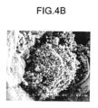
- FIG. 4B is shown in FIG. It is a SEM photograph (10000 time) which shows the part of the impurity of 4A single-walled carbon nanotube.
- FIG. 5A is an SEM photograph (30000 times) of the purified single-walled carbon nanotube produced using a graphite rod as the anode in Comparative Example 1.
- FIG. FIG. 5B is shown in FIG.
- FIG. 6 is a diagram showing a temperature-programmed desorption spectrum after exposing H 2 to the single-walled carbon nanotube sample of Example 1.
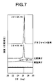
- FIG. 7 is a diagram showing the results of X-ray diffraction measurement of the amorphous carbon rod used for the anode in Example 2, the graphite rod used for the anode in Comparative Example 2, and the graphite powder as a reference example.
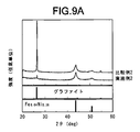
- FIG. 9A shows a crude soot produced using an amorphous carbon rod as an anode in Example 2, and a crude soot produced using a graphite rod as an anode in Comparative Example 2 immediately after synthesis from the top plate of the chamber ( It is a figure which shows the result of the X-ray-diffraction measurement of the cocoon of (before purification).
- FIG. 9A shows a crude soot produced using an amorphous carbon rod as an anode in Example 2, and a crude soot produced using a graphite rod as an anode in Comparative Example 2 immediately after synthesis from the top plate of the chamber ( It is a figure which shows the result of the X-ray-diffraction measurement of the cocoon of (before purification).
- FIG. 9B shows a crude soot produced using an amorphous carbon rod as an anode in Example 2, and a crude soot produced using a graphite rod as an anode in Comparative Example 2 immediately after synthesis from the inner wall of the chamber (purification). It is a figure which shows the result of the X-ray-diffraction measurement of the ridge of the front.
- FIG. 10A was obtained by collecting and purifying the crude iron produced using the amorphous carbon rod as the anode in Example 2 and the crude iron produced using the graphite rod as the anode in Comparative Example 2 from the top plate of the chamber. It is a figure which shows the result of X-ray diffraction measurement.
- FIG. 10A was obtained by collecting and purifying the crude iron produced using the amorphous carbon rod as the anode in Example 2 and the crude iron produced using the graphite rod as the anode in Comparative Example 2 from the top plate of the chamber. It is a figure which shows the result of X-ray
- 10B shows a crude soot produced using an amorphous carbon rod as an anode in Example 2, and a crude soot produced using a graphite rod as an anode in Comparative Example 2 from the inner surface of the side wall of the chamber and purified. It is a figure which shows the result of X-ray diffraction measurement.
- an amorphous material is produced during arc discharge.
- An anode mainly composed of carbon is used.
- an embodiment of a method for producing carbon nanotubes according to the present invention includes a step of producing an anode mainly composed of amorphous carbon, and a step of producing a soot containing single-walled carbon nanotubes by arc discharge using the anode.
- a first combustion oxidation step in which the soot containing the generated single-walled carbon nanotubes is heated and oxidized in the atmosphere at a temperature of 350 ° C. or higher, and the soot obtained in the first combustion oxidation step is converted into an acid.
- a first acid treatment step in which the soot is soaked and the soot obtained in the first acid treatment step is heated in the atmosphere at a temperature not lower than the heating temperature of the first combustion oxidation step and not lower than 500 ° C. for combustion
- the amorphous carbon rod used for the anode is preferably a carbon rod consisting essentially of amorphous carbon, but is a carbon rod mainly composed of amorphous carbon, preferably a carbon rod containing 50% by mass or more of amorphous carbon. If so, impurities and crystalline carbon may be included.
- soot containing carbon nanotubes is generated by arc discharge.
- the pair of electrodes to be attached to the chamber of the arc discharge device the above anode and a cathode made of a graphite rod are used.
- the temperature between the electrodes at the time of discharge reaches several thousand degrees Celsius, the carbon of the cathode is vaporized in the high temperature plasma, and the vaporized carbon is cooled and aggregated by the inert gas in the chamber, Soot accumulates in the chamber.
- Single-walled carbon nanotubes are contained in a large amount on the top plate of the chamber, on the inner wall and on the cathode, and multi-walled carbon nanotubes are contained in a soft black portion in the cathode deposit.
- First combustion oxidation process Next, the soot containing single-walled carbon nanotubes deposited on the top plate of the chamber, the upper part of the inner wall, and the cathode is collected.
- the soot collected in this way contains impurities such as amorphous carbon and graphite capsules containing metal in addition to single-walled carbon nanotubes.
- the impurities are burned and removed by heating at 350 to 550 ° C., more preferably 450 to 550 ° C., most preferably 500 ° C.
- the recovered soot may be heated in the atmosphere and then heated at a temperature higher than the heating temperature.
- the soot after heating is immersed in any acid such as hydrochloric acid, sulfuric acid, nitric acid, oxalic acid, left at room temperature, filtered, washed with distilled water, and dried. Residual metal catalyst can be removed.
- the obtained soot is heated at 500 ° C. or higher, preferably 500 to 600 ° C., more preferably 540 to 560 ° C., and most preferably 550 ° C. in the atmosphere to burn and remove impurities. In this way, graphite capsules other than single-walled carbon nanotubes can be burned and removed.
- (Second acid treatment step) Next, the soot after heating is immersed in hydrochloric acid and allowed to stand at room temperature, followed by filtration, washing with distilled water, and drying, whereby the metal catalyst remaining in the soot can be removed.
- the single-walled carbon nanotube thus purified after synthesis is heated in a vacuum at 1000 ° C. or higher, preferably 1000 to 1500 ° C., more preferably 1100 to 1300 ° C., and most preferably 1200 ° C.
- a defect of the carbon nanotube (defect generated in the single-walled carbon nanotube by the oxidation treatment) can be repaired.
- evaluation of carbon nanotube evaluation by Raman scattering spectroscopy
- the scattered light includes light v 0 having the same wave number as incident light (excitation light), and v 0 ⁇ v having a different wave number.
- the lattice vibration of carbon nanotubes is based on the vibration of graphite, but a new effect arises from the periodicity peculiar to carbon nanotubes.
- a vibration mode called a breathing mode appears. Since it is known that the frequency of this vibration mode is inversely proportional to the diameter of the tube, the distribution of the diameter of the tube can be known by measuring the frequency of the breathing mode by Raman scattering.
- the ratio (G / D ratio) of the spectrum intensity of the G band, which is a Raman band unique to carbon nanotubes, and the spectrum intensity of the D band derived from amorphous carbon (G / D ratio) is an index representing the purity of the single-walled carbon nanotube after synthesis. (Scale representing the degree of impurity contamination). (Evaluation by TEM image) From the TEM image of the single-walled carbon nanotube, it can be confirmed that the single-walled carbon nanotube forms a bundle and whether or not the wall surface of the single-walled carbon nanotube has a defect.
- the sample is dispersed with ultrasonic waves, sprayed onto a metal substrate with an airbrush, and then dried with a dryer to such an extent that it does not drip.
- a solvent such as ethanol
- the carbon nanotubes may be fixed to a metal substrate in the form of a sheet or film.
- the single-walled carbon nanotube manufactured in the embodiment of the carbon nanotube manufacturing method according to the present invention described above is adsorbed by blowing H 2 or D 2 as an adsorbed gas, and then increased at a temperature rising rate of 0.2 K / s.
- a disc was prepared.
- a 6 mm ⁇ 6 mm ⁇ 70 mm square bar (low graphitized carbon bar (amorphous carbon bar)) is prepared from this disc, and a hole having a diameter of 3.2 mm and a depth of 50 mm is formed in the center, and Fe, Ni , S (mass ratio 10: 10: 1) was filled with a metal catalyst made of a mixed powder to produce an anode.
- the produced anode and a cathode of a graphite rod (purity 99.9%) with a diameter of 16 mm are used, and a single layer is formed by the arc discharge method as follows. Carbon nanotubes were synthesized.
- the pair of electrodes is mounted in a chamber of an arc discharge device, the inside of the chamber is evacuated by a rotary pump, evacuated to 10 ⁇ 2 Torr, and then a direct current of 70 A is brought into contact with the anode and the cathode. And baked for 5 minutes to burn the filled metal catalyst powder and decompose hydrocarbons.
- the chamber is filled with helium gas up to 100 Torr, evacuated again to 10 -2 Torr, and then the chamber is filled with helium gas up to 100 Torr, and the distance between the electrodes is reduced to 3 mm.
- arc discharge was performed at a current of 90 A for 5 minutes.
- the arc discharge time depends on the length of the carbon rod of the anode, and the arc discharge current value is 2.5 A / mm 2 when the arc current density (arc current value per unit cross-sectional area of the anode) is 2.5 A / mm 2. It was adjusted to become.
- the soot collected in this manner contains impurities in addition to the single-walled carbon nanotubes, so the impurities were removed as follows. First, in order to remove amorphous carbon other than single-walled carbon nanotubes by combustion, the recovered soot is heated and oxidized in the atmosphere at 450 ° C. for 30 minutes, and then heated at 500 ° C. for 30 minutes for combustion oxidation. did. Next, the heated soot was immersed in 6N hydrochloric acid and allowed to stand at 60 ° C.
- the dried soot is again heated in the atmosphere at 500 ° C. for 30 minutes for combustion oxidation.
- the heated soot is immersed in 6N hydrochloric acid and left at 60 ° C. for 12 hours or longer, then filtered, and filtered at 60 ° C. Dried for 12 hours or more.
- the dried soot was heated (annealed) at 1200 ° C. for 3 hours in a vacuum of 10 ⁇ 7 Torr to obtain purified single-walled carbon nanotubes.
- Comparative Example 1 Example 1 described above except that instead of the amorphous carbon rod, a graphite rod (purity 99.9%) having a diameter of 3.2 mm and a hole having a depth of 85 mm formed with a diameter of 6 mm and a length of 100 mm was used. Single-walled carbon nanotubes were synthesized and purified by the same method.
- XRD X-ray diffraction
- the carbon rod used for the anode in Example 1 is a disordered layer having no regular layer structure. It can be seen that this is a low-graphitization carbon rod composed of a structure.
- the mass loss percentage curve when the amorphous carbon rod used for the anode in Example 1 and the graphite rod used for the anode in Comparative Example 1 were heated in the atmosphere at a heating rate of 5 ° C./min is shown in FIG. It is shown in 2.
- the oxidation start temperature of graphite is 700 ° C.
- the low graphitization carbon material has an oxidation start temperature of 400 to 600 ° C., depending on the degree of graphitization. In this way, the oxidation start temperature of the carbon material having a low graphitization degree is low.
- the turbulent layer structure that is not a graphite structure, many edges of graphene that are reaction fields with oxygen are exposed, This is because it is a graphene of the order of several nanometers, so that it becomes a thermally unstable structural state.
- FIG. As shown in FIG.
- the graphite rod used for the anode in Comparative Example 1 shows a mass reduction from about 700 ° C.
- the amorphous carbon rod used for the anode in Example 1 shows a mass reduction from about 500 ° C.
- the carbon rod used for the anode in Example 1 is a low-graphitization carbon rod composed of a turbulent layer structure having no regular layer structure.
- the XRD profiles of single-walled carbon nanotubes immediately after and after purification are shown in FIG. 3 shows.
- a scanning electron microscope (SEM) photograph of the purified single-walled carbon nanotube produced using an amorphous carbon rod for the anode in Example 1 is shown in FIG. 4A and FIG.
- FIG. 4B an SEM photograph of a purified single-walled carbon nanotube produced using a graphite rod as the anode in Comparative Example 1 is shown in FIG. 5A and FIG. Shown in 5B.
- FIG. 5A in addition to the observation of single-walled carbon nanotubes, FIG. As shown in 5B, a large lump of graphite of 10 to 30 ⁇ m was observed. The strong graphite peak in the XRD profile is thought to be due to this graphite mass. It is considered that the graphite lump is caused by the fact that the anode graphite rod at the time of arc discharge was not sublimated and was sputtered as graphite by arc discharge. On the other hand, FIG. As shown in FIG.
- single-walled carbon nanotubes were observed uniformly.
- an agglomerate having a size of 1 to 3 ⁇ m in which nanoparticles having a size of several nm considered to be graphite capsules covering the metal catalyst were agglomerated was observed.
- the peak intensity of graphite on the (002) plane in the X-ray diffraction (XRD) profile per unit mass of the single-walled carbon nanotubes immediately after synthesis and after purification was 2.6 cps / mg in the first measurement, The second measurement was 0 cps / mg and 80 cps / gm, respectively.
- the measurement of the peak intensity of graphite on the (002) plane in the X-ray diffraction (XRD) profile per unit mass of the single-walled carbon nanotubes immediately after the synthesis produced in Comparative Example 1 was performed twice.
- the Raman scattering spectroscopic measurement of single-walled carbon nanotubes immediately after synthesis and after purification which was produced using an amorphous carbon rod as the anode in Example 1, was performed twice.
- the Raman intensity ratio (D / G) of the single-walled carbon nanotubes immediately after synthesis and after purification was 23.5 and 85.0, respectively, in the first Raman scattering spectroscopy measurement, and the second Raman scattering spectroscopy. In the measurement, they were 40.0 and 100, respectively.
- the Raman scattering spectroscopic measurement of the single-walled carbon nanotubes immediately after synthesis and after purification produced in Comparative Example 1 was performed twice.
- the Raman intensity ratio (D / G) of the single-walled carbon nanotubes immediately after synthesis and after purification was 34.5 and 76.0, respectively, in the first Raman scattering spectroscopy measurement, and the second Raman scattering spectroscopy. In the measurement, they were 52.6 and 80.0, respectively.
- the purified single-walled carbon nanotube produced using an amorphous carbon rod as the anode in Example 1 has a very high Raman intensity ratio (D / G) of 85 to 100 and a purity of It is very high. This means that the amount of graphite in the unit volume is very small, so that impurities are very small and the purity of the carbon nanotube is very high.
- the sample length (tube length) was about 1 to 3 ⁇ m, and the total length of the tube was relatively long. It was a single-walled carbon nanotube called a junction type.
- the single-walled carbon nanotube obtained in Example 1 is a carbon nanotube having no defects or almost no defects. Also, a quadrupole mass spectrometer for temperature programmed desorption spectrum measurement and a gas dozer having an orifice (pore) with a diameter of 20 ⁇ m for gas exposure for directly blowing gas onto a sample fixed to a metal substrate were provided.
- Example 1 the temperature of the sample of the single-walled carbon nanotube obtained in Example 1 is maintained at 13K, and H 2 or D 2 is sprayed on each sample as an adsorbed gas at a flow rate of 1 L / s to be adsorbed. Thereafter, the temperature was increased at a rate of temperature increase of 0.2 K / s, and the temperature-programmed desorption spectrum was measured.
- the recovery rate of the purified single-walled carbon nanotubes produced using the amorphous carbon rod for the anode in Example 1 is 5 to 10% by mass with respect to the single-walled carbon nanotubes immediately after synthesis, and the purity is 99. % Or more (0.5% by mass or less of metal, 0.5% by mass or less of carbon nanocapsules).
- Comparative Example 2 Petroleum needle-shaped coke mixed with particle size is blended with a coal tar pitch (binding material) with a softening point of 98 ° C. and fixed carbon of 58% as a binder at a ratio of 30% by mass, and thoroughly mixed at 140 ° C. with a Werner compounding machine. Thus, a uniform paste was produced.
- This paste was filled in a container of an extrusion molding apparatus, and an axial core mandrel was attached to a cylindrical nozzle to obtain a molded body with an extrusion pressure of 40 kg / cm 2 or more.
- This molded body was placed in a firing furnace and calcined at 1000 ° C., and then placed in an LWG furnace, graphitized at 3000 ° C., diameter 6 mm, length 100 mm, center diameter 3.2 mm, depth A rod having a 70 mm hole (graphite rod) was obtained.
- iron powder 100 mesh iron powder manufactured by Wako Pure Chemical Industries, Ltd.
- nickel powder 100 mesh nickel powder manufactured by Wako Pure Chemical Industries, Ltd.
- sulfur High Purity 5 manufactured by Mitsuwa Chemicals Co., Ltd.
- graphite powder manufactured by Wako Pure Chemical Industries, Ltd.
- CFx Poly (carbon monofluoride)
- a metal catalyst comprising a mixed powder having a ratio of 30: 10: 10: 1: 1) was prepared, and the anode was prepared by filling the metal catalyst into a hole of a graphite rod.
- the produced anode and a cathode of a graphite rod (purity 99.9%) with a diameter of 16 mm are used, and a single layer is formed by the arc discharge method as follows. Carbon nanotubes were synthesized.
- the above-mentioned pair of electrodes is mounted in a chamber of an arc discharge device, the inside of the chamber is evacuated by a rotary pump and evacuated to 10 ⁇ 2 Torr, and then 28.6A ( A current density of 1.01 A / mm 2 ) for 3 minutes, a current of 37.9 A (current density of 1.34 A / mm 2 ) for 3 minutes, and a current of 47.5 A (current density of 1.68 A / mm 2 ). 3 minutes, 56.8A (current density 2.01A / mm 2) current 3 minutes, an annealing treatment was performed by applying a current of 66.4A (current density 2.35A / mm 2) 5 min.
- the current density is a current value per unit cross-sectional area of the anode, and is a value obtained by dividing the current value by the cross-sectional area of the rod 28.26 mm 2 .
- the chamber was filled with helium gas up to 100 Torr, and an arc discharge was performed by flowing a current of 75.8 A (current density 2.68 A / mm 2 ) while maintaining the distance between the electrodes at 3 mm.
- This arc discharge ended when the anode was consumed to some extent.
- soot accumulated on the top plate and side wall inner surface of the chamber was collected.
- the soot collected in this manner contains impurities in addition to the single-walled carbon nanotubes, so the impurities were removed as follows.
- the collected soot is put in a SUS container with good air permeability, installed in a muffle furnace (FM37 manufactured by Yamato Scientific Co., Ltd.), and 450% in the air.
- the mixture was heated and oxidized at 30 ° C. for 30 minutes, followed by combustion and oxidation at 500 ° C. for 30 minutes.
- the soot after combustion oxidation is put into the screw robin, and a 6N hydrochloric acid solution (35.0 to 37.0% by mass of reagent special grade hydrochloric acid manufactured by Wako Pure Chemical Industries, Ltd.) and purified water are mixed at a volume of 1: 1.
- a disc was prepared.
- a 6 mm ⁇ 6 mm ⁇ 70 mm square bar (low graphitized carbon bar (amorphous carbon bar)) was produced from this disc, and a hole having a diameter of 3.2 mm and a depth of 50 mm was formed in the center.
- the corner of this square bar was dropped with sandpaper to make an octagonal cross section. Comparative Example 2 except that instead of graphite powder (manufactured by Wako Pure Chemical Industries, Ltd.), the powder produced when a hole was made in an amorphous carbon rod and the corner was dropped to be processed into an octagonal rod was used.
- An anode was prepared by filling a hole of an amorphous carbon rod with a metal catalyst made of the same mixed powder as in Example 1. Next, using the produced anode, a current of 30.0 A (current density 1.01 A / mm 2 ) was applied for 3 minutes, a current of 40.0 A (current density 1.34 A / mm 2 ) was applied for 3 minutes, 50 0.0A (current density 1.68 A / mm 2 ) for 3 minutes, 60.0 A (current density 2.01 A / mm 2 ) for 3 minutes, 70.0 A (current density 2.35 A / mm 2 ) Comparative Example 2 except that an annealing treatment was performed by flowing a current of 5 minutes, and an arc discharge was performed by flowing a current of 80.0 A (current density 2.68 A / mm 2 ) in a state where the anode and the cathode were in contact with each other.
- the soot containing the synthesized single-walled carbon nanotubes was collected by the same method.
- the current density is a value obtained by dividing the current value by the cross-sectional area of the rod 29.82 mm 2 . Since the soot collected in this manner contains impurities in addition to the single-walled carbon nanotubes, the purified single-walled carbon nanotubes are removed by removing impurities by the same method as in Comparative Example 2. Obtained.
- the average spacing d of these (002) planes is 0.3357 nm and 0.3366 nm, respectively, which is in good agreement with the theoretical diffraction angle of the XRD profile of graphite and the average spacing d of the (002) plane. From these facts, it can be said that the graphite crystal structure is highly developed.
- the value smaller than the average interplanar spacing d of (002) plane of hexagonal graphite is that the diffraction angle of rhombohedral graphite is 26.60 °, and the average interplanar spacing d of (002) plane. Is 0.3349 nm, it is considered that this is because rhombohedral graphite exists. This is considered to be because when graphite powder having a highly developed graphite structure is refined, stress is applied to the structure and the structure is transferred to rhombohedral graphite.
- FIG. As shown in FIG.
- the amorphous carbon rod used for the anode in Example 2 the graphite rod used for the anode in Comparative Example 2, and the graphite powder as a reference example (manufactured by Wako Pure Chemical Industries, Ltd.) in the atmosphere at a temperature rising rate of 5
- the mass loss percentage curve when the temperature is raised at 0 ° C./min is shown in FIG. It is shown in FIG.
- the carbon substance reacts with oxygen, CO and CO 2 are generated. Therefore, it is possible to investigate at which temperature the carbon substance reacts with oxygen by mass thermal analysis of the carbon material in the atmosphere.
- the oxidation start temperature of graphite is 700 ° C.
- the low graphitization carbon material has an oxidation start temperature of 400 to 600 ° C., depending on the degree of graphitization. In this way, the oxidation start temperature of the carbon material having a low graphitization degree is low.
- the turbulent layer structure that is not a graphite structure, many edges of graphene that are reaction fields with oxygen are exposed, This is because it is a graphene of the order of several nanometers, so that it becomes a thermally unstable structural state.
- FIG. As shown in FIG. 8, in the graphite powder as a reference example and the graphite rod used for the anode in Comparative Example 2, a mass reduction is observed from about 600 ° C.
- the amorphous carbon rod used for the anode in Example 2 mass reduction is recognized from about 500 ° C. Also from these results, it can be seen that the amorphous carbon rod used for the anode in Example 2 is a low-graphitization carbon rod composed of a turbulent layer structure having no regular layer structure. (Evaluation of single-walled carbon nanotubes produced in Example 2 and Comparative Example 2) Immediately after synthesizing the crude soot produced using an amorphous carbon rod as the anode in Example 2 and the crude soot produced using the graphite rod as the anode in Comparative Example 2 (before purification), respectively.
- X-ray diffraction (XRD) profile of The X-ray diffraction (XRD) profile of the soot immediately after synthesis (before purification) in which the crude soot produced using these amorphous carbon rods and graphite rods is recovered from the inner surface of the side wall of the chamber is shown in FIG. Shown in 9B.
- the crude soot produced using an amorphous carbon rod as the anode in Example 2 and the crude soot produced using the graphite rod as the anode in Comparative Example 2 were recovered from the top plate of the chamber and purified.
- X-ray diffraction (XRD) profile is shown in FIG. FIG.
- 10A shows the X-ray diffraction (XRD) profile of the soot that was obtained by collecting the crude soot produced using these amorphous carbon rods and graphite rods from the inner surface of the side wall of the chamber and purifying them. Shown in 10B.
- the crude soot produced using an amorphous carbon rod as the anode in Example 2 and the crude soot produced using the graphite rod as the anode in Comparative Example 2 were collected from the inner surface of the side wall of the chamber immediately after the synthesis (before purification). ) was observed with a scanning electron microscope (SEM).
- Particles having a diameter of about 30 to 150 nm and small particles having a diameter of about 10 nm were observed.
- Particles with a diameter of about 30 to 150 nm are considered to be particles mixed by sputtering from the anode, and particles with a diameter of about 10 nm are considered to be graphite generated from atomic carbon evaporated and sublimated by arc discharge. It is done.
- the crude soot produced using the amorphous carbon rod as the anode in Example 2 and the crude soot produced using the graphite rod as the anode in Comparative Example 2 were collected from the inner surface of the side wall of the chamber (purification). The Raman scattering spectroscopic measurement of the cocoon before and after purification was performed.
- Example 2 the Raman intensity ratio (D / G) of soot immediately after synthesis (before purification) and after purification was 13.8 to 14.1 and 92.7 to 113.2, respectively.
- Table 3 the crude strength produced using the amorphous carbon rod as the anode in Example 2 was recovered from the inner surface of the side wall of the chamber and purified, and the Raman intensity ratio (D / G) was 92.7. It is very high at ⁇ 113.2 and the purity is very high. This means that the amount of graphite in the unit volume is very small, so that impurities are very small and the purity of the carbon nanotube is very high.
Abstract
アーク放電による合成直後の粗製煤中にグラファイトが殆ど含まれないようにして、簡易な精製により製造することができる、高純度のカーボンナノチューブおよびその製造方法を提供する。アモルファスカーボンを主成分とする陽極を使用してアーク放電により生成したカーボンナノチューブを含む煤を大気中において350℃以上の温度で加熱して燃焼酸化し、酸に浸して処理し、大気中において前の燃焼酸化における加熱温度以上且つ500℃以上の温度で加熱して燃焼酸化し、再び酸に浸して処理する。
Description
本発明は、カーボンナノチューブおよびその製造方法に関し、特に、単層カーボンナノチューブおよびその製造方法に関する。
カーボンナノチューブは、黒鉛結晶の薄層を円筒状に巻いた構造、すなわち、炭素分子の六員環が亀甲模様のように配列した平面状または曲面状のグラフェンシートを円筒状に巻いた構造を有し、その直径は数nm~数十nm、長さは直径の数十倍~数千倍以上である。このようなカーボンナノチューブは、円筒状に巻いたグラフェンシートが実質的に1層である単層カーボンナノチューブと、2層以上である多層カーボンナノチューブに分類される。
単層カーボンナノチューブは、外径が小さく、表面エネルギーが大きいので、一本のチューブとして存在せず、複数のチューブが寄り集まってバンドルを形成することによって安定化を図っている。また、多層カーボンナノチューブは、導電性、高弾性、高強度などの特性を有しているが、単層カーボンナノチューブは、金属性や半導体性になるという電気的特性、極めて強靭で高弾性を有するという機械的特性、ダイヤモンドより優れた熱伝導性、分子の吸着吸蔵特性など、多層カーボンナノチューブとは異なる特性を有している。このような特性により、単層カーボンナノチューブは、水素吸蔵材料、静電防止剤、導電性インク、電界効果トランジスタ、燃料電池触媒担体、二次電池負極材など、種々の技術分野に応用することが期待されている。
一般に、カーボンナノチューブは、アーク放電法、レーザー蒸着法、熱CVD法などの各種の方法によって製造されている。これらの方法のうち、アーク放電法は、不活性ガス中で数mmの間隔で配置された炭素電極間に電圧を印加してアーク放電により陰極にカーボンナノチューブを堆積させる方法であり(例えば、特開2004−210555号公報および特開2006−16282号公報参照)、他の方法と比べて、構造欠陥が少ないカーボンナノチューブを安価に生成することができる。アーク放電法では、炭素棒に充填する触媒金属の有無によって単層カーボンナノチューブと多層カーボンナノチューブを作り分けることができ、また、触媒金属の種類によってチューブの直径や長さを制御することもできる。
しかし、特開2004−210555号公報および特開2006−16282号公報の方法のような従来のアーク放電によるカーボンナノチューブの製造方法では、陽極として触媒金属を充填したグラファイト(黒鉛)棒を使用しており、アーク放電による合成直後の粗製煤中に、アモルファスカーボン、金属触媒のナノ粒子(数nmの大きさの微粒子)、グラファイト棒からスパッタリングされたグラファイトが多く含まれ、合成されたカーボンナノチューブの純度が低いという問題がある。これらのうち、アモルファスカーボンは、粗製煤を燃焼酸化させることによって容易に除去することができ、金属触媒は、粗製煤を酸処理することによって容易に除去することができる。しかし、粗製煤からグラファイトを除去するためには、粗製煤に界面活性剤を添加した遠心分離や、サイズクロマトグラフィーなどを行う必要であるため、手間と時間がかかる。また、このような精製工程を行うことによって、カーボンナノチューブの構造に欠陥を与えるという問題がある。
したがって、本発明は、上述した従来の問題点に鑑み、アーク放電による合成直後の粗製煤中にグラファイトが殆ど含まれないようにして、簡易な精製により製造することができる、高純度のカーボンナノチューブおよびその製造方法を提供することを目的とする。
本発明者らは、上記課題を解決するために鋭意研究した結果、アーク放電用の陽極として、低温で燃焼酸化するアモルファスカーボン棒(低黒鉛化度炭素棒)を使用することにより、アーク放電による合成直後の粗製煤中にグラファイトが殆ど含まれず、簡易な精製により高純度のカーボンナノチューブを製造することができることを見出し、本発明を完成するに至った。
すなわち、本発明によるカーボンナノチューブの製造方法は、アーク放電によりカーボンナノチューブを含む煤を生成した後、得られた煤を精製することによってカーボンナノチューブを製造する方法において、アーク放電の際にアモルファスカーボンを主成分とする陽極を使用することを特徴とする。
このカーボンナノチューブの製造方法において、アモルファスカーボンを主成分とする陽極が、アモルファスカーボンを50質量%以上含むのが好ましく、また、金属触媒を含むのが好ましい。また、アモルファスカーボンを主成分とする陽極が、カーボンブラックとコールタールピッチの混合物を焼成して得られたアモルファスカーボン棒に形成された穴に金属触媒が充填された陽極であるのが好ましい。さらに、金属触媒がFeとNiとSを含む混合粉末からなるのが好ましい。
また、カーボンナノチューブを含む煤の精製は、カーボンナノチューブを含む煤を大気中において350℃以上の温度で加熱して燃焼酸化する第1の燃焼酸化工程を含むのが好ましく、この第1の燃焼酸化工程で得られた煤を酸に浸して処理する第1の酸処理工程を含むのが好ましく、この第1の酸処理工程で得られた煤を大気中において第1の燃焼酸化工程の加熱温度以上且つ500℃以上の温度で加熱して燃焼酸化する第2の燃焼酸化工程を含むのが好ましく、この第2の燃焼酸化工程で得られた煤を酸に浸して処理する第2の酸処理工程を含むのが好ましく、この第2の酸処理工程で得られた煤を真空中において加熱する真空加熱処理工程を含むのが好ましい。また、この真空加熱処理工程の加熱温度が1000℃以上であるのが好ましい。さらに、カーボンナノチューブが単層カーボンナノチューブであるのが好ましい。
また、本発明によるカーボンナノチューブは、ラマン散乱分光測定において、カーボンナノチューブ固有のラマンバンドであるGバンドのスペクトルの強度と、アモルファスカーボン由来のDバンドのスペクトルの強度の比(G/D比)が85~115であることを特徴とする。このカーボンナノチューブは、吸着気体としてH2またはD2を吹き付けて吸着させた後、昇温速度0.2K/sで昇温させて測定された昇温脱離スペクトルにおいて、温度19.0~22.0Kに半値幅1.0K以下のピークを有するのが好ましい。また、このカーボンナノチューブは、透過型電子顕微鏡(TEM)像において、100nm四方に1nm程度の欠陥が10個以下であるのが好ましい。さらに、このカーボンナノチューブは、単層カーボンナノチューブであるのが好ましい。
さらに、本発明による単層カーボンナノチューブ製造用陽極は、アモルファスカーボンを主成分とすることを特徴とする。この単層カーボンナノチューブ製造用陽極において、陽極がアモルファスカーボンを50質量%以上含むのが好ましい。また、この陽極は、金属触媒を含むのが好ましく、カーボンブラックとコールタールピッチの混合物を焼成して得られたアモルファスカーボン棒に形成された穴に金属触媒が充填された陽極であるのが好ましい。
本発明によれば、アーク放電による合成直後の粗製煤中にグラファイトが殆ど含まれないようにして、簡易な精製により高純度のカーボンナノチューブを製造することができる。
Fig.1は、実施例1において陽極に使用したアモルファスカーボン棒と、比較例1において陽極に使用したグラファイト棒のX線回折測定の結果を示す図である。
Fig.2は、実施例1において陽極に使用したアモルファスカーボン棒と、比較例1において陽極に使用したグラファイト棒を大気中において昇温速度5℃/分で昇温させたときの質量減少百分率曲線を示す図である。
Fig.3は、実施例1において陽極にアモルファスカーボン棒を使用して製造した合成直後と精製後の単層カーボンナノチューブのX線回折(XRD)プロファイルと、比較例1において陽極にグラファイト棒を使用して製造した合成直後と精製後の単層カーボンナノチューブのXRDプロファイルを示す図である。
Fig.4Aは、実施例1において陽極にアモルファスカーボン棒を使用して製造した精製後の単層カーボンナノチューブの走査電子顕微鏡(SEM)写真(30000倍)である。
Fig. 4Bは、Fig.4Aの単層カーボンナノチューブの不純物の部分を示すSEM写真(10000倍)である。
Fig.5Aは、比較例1において陽極にグラファイト棒を使用して製造した精製後の単層カーボンナノチューブのSEM写真(30000倍)である。
Fig.5Bは、Fig.5Aの単層カーボンナノチューブのグラファイトの部分を示すSEM写真(1000倍)である。
Fig.6は、実施例1の単層カーボンナノチューブの試料にH2を曝露した後の昇温脱離スペクトルを示す図である。
Fig.7は、実施例2において陽極に使用したアモルファスカーボン棒と、比較例2において陽極に使用したグラファイト棒と、参考例としてのグラファイト粉末のX線回折測定の結果を示す図である。
Fig.8は、実施例2において陽極に使用したアモルファスカーボン棒と、比較例2において陽極に使用したグラファイト棒と、参考例としてのグラファイト粉末を大気中において昇温速度5℃/分で昇温させたときの質量減少百分率曲線を示す図である。
Fig.9Aは、実施例2において陽極にアモルファスカーボン棒を使用して製造した粗製煤と、比較例2において陽極にグラファイト棒を使用して製造した粗製煤をそれぞれチャンバの天板から回収した合成直後(精製前)の煤のX線回折測定の結果を示す図である。
Fig.9Bは、実施例2において陽極にアモルファスカーボン棒を使用して製造した粗製煤と、比較例2において陽極にグラファイト棒を使用して製造した粗製煤をチャンバの側壁内面から回収した合成直後(精製前)の煤のX線回折測定の結果を示す図である。
Fig.10Aは、実施例2において陽極にアモルファスカーボン棒を使用して製造した粗製煤と、比較例2において陽極にグラファイト棒を使用して製造した粗製煤をチャンバの天板から回収して精製した煤のX線回折測定の結果を示す図である。
Fig.10Bは、実施例2において陽極にアモルファスカーボン棒を使用して製造した粗製煤と、比較例2において陽極にグラファイト棒を使用して製造した粗製煤をチャンバの側壁内面から回収して精製した煤のX線回折測定の結果を示す図である。
[カーボンナノチューブの製造]
本発明によるカーボンナノチューブの製造方法の実施の形態では、アーク放電によりカーボンナノチューブを含む煤を生成した後、得られた煤を精製することによってカーボンナノチューブを製造する方法において、アーク放電の際にアモルファスカーボンを主成分とする陽極を使用する。例えば、本発明によるカーボンナノチューブの製造方法の実施の形態は、アモルファスカーボンを主成分とする陽極を作製する工程と、この陽極を使用してアーク放電により単層カーボンナノチューブを含む煤を生成する工程と、生成された単層カーボンナノチューブを含む煤を大気中において350℃以上の温度で加熱して燃焼酸化する第1の燃焼酸化工程と、この第1の燃焼酸化工程で得られた煤を酸に浸して処理する第1の酸処理工程と、この第1の酸処理工程で得られた煤を大気中において第1の燃焼酸化工程の加熱温度以上且つ500℃以上の温度で加熱して燃焼酸化する第2の燃焼酸化工程と、この第2の燃焼酸化工程で得られた煤を酸に浸して処理する第2の酸処理工程とを備えている。また、第2の酸処理工程で得られた煤を真空中において加熱する真空加熱処理工程とを備えてもよい。以下、これらの工程について詳細に説明する。
(陽極作製工程)
カーボンブラックにコールタールピッチを添加して混合し、粘土状の硬さになったら、固練り(硬いケーキ状の状態における混合に時間をかける操作)を行って、混合物にせん断を作用させて混ざりを良くし、この固練り終了後、円板状のモールドに詰めて、所定の温度(例えば130℃)で所定の圧力(例えば50kg/cm2)を加えて成形する。次に、モールドを外して、窒素雰囲気下において加熱して焼成を行った後、徐冷し、円板を作製し、この円板からアモルファスカーボン棒(低黒鉛化度炭素棒)を作製し、このアモルファスカーボン棒の中心に穴を開け、この穴にFe、Ni、S(質量比10:10:1)またはC、Fe、Ni、S、CFx(質量比30:10:10:1:1)の混合粉末からなる金属触媒を充填して陽極を作製する。
なお、陽極に使用するアモルファスカーボン棒は、実質的にアモルファスカーボンのみからなる炭素棒であるのが好ましいが、アモルファスカーボンを主成分とする炭素棒、好ましくはアモルファスカーボンを50質量%以上含む炭素棒であれば、不純物や結晶性カーボンを含んでもよい。
(カーボンナノチューブ生成工程)
まず、アーク放電によりカーボンナノチューブを含む煤を生成する。アーク放電装置のチャンバに装着する一対の電極として、上記の陽極と、グラファイト棒からなる陰極を使用する。なお、アーク放電法では、放電時の電極間の温度が数千℃に達し、陰極の炭素が高温のプラズマ中に気化し、気化した炭素がチャンバ内の不活性ガスによって冷却されて凝集し、チャンバ内に煤が堆積する。単層カーボンナノチューブは、チャンバの天板、内壁上部および陰極に堆積した煤に多く含まれており、多層カーボンナノチューブは、陰極堆積物中の柔らかい黒色部分に多く含まれている。
(第1の燃焼酸化工程)
次に、チャンバの天板、内壁上部および陰極に堆積した単層カーボンナノチューブを含む煤を回収する。このようにして回収された煤中には、単層カーボンナノチューブの他にアモルファスカーボンや金属を含むグラファイトカプセルなどの不純物が含まれているので、回収した煤を大気中において350℃以上、好ましくは350~550℃、さらに好ましくは450~550℃、最も好ましくは500℃で加熱することによって不純物を燃焼させて除去する。このようにして、単層カーボンナノチューブ以外のアモルファスカーボンを燃焼させて除去することができる。また、回収した煤中には、フラーレンや、金属触媒を包含しているフラーレンが存在しており、この加熱によってフラーレンを破壊することもできる。なお、この第1の燃焼酸化工程では、回収した煤を大気中において加熱した後、その加熱温度より高い温度で加熱してもよい。
(第1の酸処理工程)
次に、この加熱後の煤を塩酸、硫酸、硝酸、シュウ酸などのいずれかの酸に浸し、室温下で放置した後、ろ過し、蒸留水で洗浄し、乾燥することによって、煤中に残留している金属触媒を除去することができる。
(第2の燃焼酸化工程)
次に、得られた煤を大気中において500℃以上、好ましくは500~600℃、さらに好ましくは540~560℃、最も好ましくは550℃で加熱することによって、不純物を燃焼させて除去する。このようにして、単層カーボンナノチューブ以外のグラファイトカプセルを燃焼させて除去することができる。
(第2の酸処理工程)
次に、この加熱後の煤を塩酸に浸し、室温下で放置した後、ろ過し、蒸留水で洗浄し、乾燥することによって、煤中に残留している金属触媒を除去することができる。
(真空加熱処理工程)
その後、このようにして合成後に精製した単層カーボンナノチューブを真空中において1000℃以上、好ましくは1000~1500℃、さらに好ましくは1100~1300℃、最も好ましくは1200℃で加熱することによって、単層カーボンナノチューブの欠陥(酸化処理によって単層カーボンナノチューブに生じた欠陥)を修復することができる。
[カーボンナノチューブの評価]
(ラマン散乱分光法による評価)
一般に、光を物質に入射すると、光の一部が非弾性的に散乱され、散乱光には、入射光(励起光)と同じ波数の光v0の他に、波数の異なるv0±vRの光がごく僅かだけ含まれている。この現象はラマン効果と呼ばれ、励起光と分子振動や固体のフォノンまたはその他の素励起などとの相互作用による散乱はラマン散乱と呼ばれている。生じた励起光との波数のずれvRは、ラマンシフトと呼ばれ、物質に固有な値となる。従って、ラマン散乱を測定すれば、物質中の素励起の状態を調べることができ、また、温度や圧力を変化させてラマン散乱を測定すれば、散乱強度やピーク位置のシフトなどの変化から物質内の状態の変化を調べることができる。
ラマン散乱分方法をカーボンナノチューブの評価に用いる場合、カーボンナノチューブの格子振動は、グラファイトの振動が基本となっているが、カーボンナノチューブ特有の周期性から新たな効果が生じる。例えば、1枚のグラフェンシートを継ぎ目なく円筒状に巻くと、ブリージングモードと呼ばれる振動モードが出現する。この振動モードの振動数はチューブの直径に反比例することが知られているので、ラマン散乱によりブリージングモードの振動数を測定すると、チューブの直径の分布を知ることができる。
また、カーボンナノチューブ固有のラマンバンドであるGバンドのスペクトルの強度と、アモルファスカーボン由来のDバンドのスペクトルの強度の比(G/D比)を、合成後の単層カーボンナノチューブの純度を表す指標(不純物の混入度合いを表す尺度)とすることができる。
(TEM像による評価)
単層カーボンナノチューブのTEM像から、単層カーボンナノチューブがバンドルを形成していることや、単層カーボンナノチューブの壁面に欠陥が生じているか否かを確認することができる。
(昇温脱離法による評価)
昇温脱離スペクトル測定用の四重極質量分析計と、試料に気体を直接吹き付けるための気体曝露用のオリフィス(細孔)を有するガスドーザーとを備えた装置を使用して、単層カーボンナノチューブに、吸着気体としてH2またはD2を吹き付けて吸着させた後、昇温させて昇温脱離スペクトル(TDS)を測定することにより、昇温脱離スペクトルのピーク温度やピーク形状から、単層カーボンナノチューブの欠陥の有無を判断することができる。
なお、単層カーボンナノチューブの試料の昇温脱離スペクトルを測定するためには、単層カーボンナノチューブの粉状の試料を金属基板に固定する必要がある。例えば、単層カーボンナノチューブを含む煤をエタノールなどの溶媒に入れた後に、超音波で分散させ、これを金属基板にエアブラシなどで吹き付けた後、液垂れしない程度にドライヤーで乾燥することによって、試料を金属基板に固定することができる。あるいは、カーボンナノチューブをシートまたはフィルム状にして金属基板に固定してもよい。
上述した本発明によるカーボンナノチューブの製造方法の実施の形態に製造された単層カーボンナノチューブは、吸着気体としてH2またはD2を吹き付けて吸着させた後、昇温速度0.2K/sで昇温させて測定された昇温脱離スペクトルにおいて、温度19.0~22.0Kに半値幅1.0K以下のピークを有する。この単層カーボンナノチューブは、透過型電子顕微鏡(TEM)による格子像が鮮明に観察され、例えば、TEM像で100nm四方に1nm程度の欠陥が10個以下しか確認されないので、欠陥が存在しないか、あるいは欠陥が殆どない単層カーボンナノチューブであると評価することができる。一方、このようなピークを有しない単層カーボンナノチューブは、格子欠陥が多い単層カーボンナノチューブであると評価することができる。
以下、本発明によるカーボンナノチューブおよびその製造方法の実施例について詳細に説明する。
60質量%のカーボンブラック(東海カーボン株式会社製のシーストTA)に40質量%のコールタールピッチを添加して混合した。粘土状の硬さになったら、固練り(硬いケーキ状の状態における混合に時間をかける操作)を3時間行って、混合物にせん断を作用させて混ざりを良くした。この固練り終了後、円板状(直径約100mm、厚さ20mm)のモールドに詰めて、130℃で50kg/cm2の圧力を3分間加えて成形した。次に、モールドを外して、窒素雰囲気下において昇温速度5℃/分で1000℃まで加熱し、この温度で2時間保持して焼成を行った後、徐冷し、直径100mm、厚さ20mmの円板を作製した。この円板から6mm×6mm×70mmの角棒(低黒鉛化度炭素棒(アモルファスカーボン棒))を作製し、中心に直径3.2mm、深さ50mmの穴を開け、この穴にFe、Ni、S(質量比10:10:1)の混合粉末からなる金属触媒を充填して陽極を作製した。
次に、アーク放電装置のチャンバに装着する一対の電極として、作製した陽極と、直径16mmのグラファイト棒(純度99.9%)の陰極を使用して、以下のようにアーク放電法により単層カーボンナノチューブを合成した。
まず、上記の一対の電極をアーク放電装置のチャンバに装着し、チャンバ内をロータリーポンプで排気して10−2Torrまで真空引きした後、陽極と陰極を接触させた状態で、70Aの直流電流を流し、5分間ベーキング処理して、充填した金属触媒の粉末を焼成させるとともに、炭化水素を分解させた。次に、チャンバ内を30分間冷却した後、チャンバ内にヘリウムガスを100Torrまで満たし、再び10−2Torrまで真空引きし、その後、チャンバ内にヘリウムガスを100Torrまで満たし、電極間距離を3mmに保ちながら90Aの電流で5分間アーク放電を行った。なお、このアーク放電時間は、陽極の炭素棒の長さに依存し、また、アーク放電の電流値は、アーク電流密度(陽極の単位断面積あたりのアーク電流値)が2.5A/mm2になるように調整した。このアーク放電の終了後、30分間冷却し、チャンバの天板および内壁上部に堆積した煤と、陰極に堆積した煤を回収した。
このようにして回収された煤中には、単層カーボンナノチューブの他に不純物が含まれているので、以下のように不純物を除去した。
まず、単層カーボンナノチューブ以外のアモルファスカーボンを燃焼によって除去するために、回収した煤を大気中において450℃で30分間加熱して燃焼酸化した後、続けて500℃で30分間加熱して燃焼酸化した。次に、この加熱後の煤を6Nの塩酸に浸して60℃で12時間以上放置した後、ろ過し、60℃で12時間以上乾燥した。この乾燥後の煤を再び大気中において500℃で30分間加熱して燃焼酸化し、この加熱後の煤を6Nの塩酸に浸して60℃で12時間以上放置した後、ろ過し、60℃で12時間以上乾燥した。この乾燥後の煤を10−7Torrの真空中において1200℃で3時間加熱(アニール)し、精製された単層カーボンナノチューブを得た。
比較例1
アモルファスカーボン棒の代わりに、中心に直径3.2mm、深さ85mmの穴が形成された直径6mm、長さ100mmのグラファイト棒(純度99.9%)を使用した以外は、上述した実施例1と同様の方法により、単層カーボンナノチューブを合成し、精製した。
(実施例1および比較例1において陽極に使用した炭素棒の評価)
実施例1において陽極に使用したアモルファスカーボン棒と、比較例1において陽極に使用したグラファイト棒のX線回折(XRD)プロファイルをFig.1に示す。
天然黒鉛またはHOPG(Highly Oriented Pyrolytic Graphite(高配向性熱分解グラファイト))のようなグラファイトでは、C軸方向の面間隔、すなわち(002)面の面間隔が0.335nmであり、XRDプロファイルに2θ=26.4°にピークが現れる。また、結晶子が長周期にわたって発達しているので回折強度も大きい。したがって、比較例1において陽極に使用したグラファイト棒のXRDプロファイルでは、Fig.1に示すように、2θ=26.4°に回折強度が大きいピークが現れている。
一方、実施例1において陽極に使用したアモルファスカーボン棒のXRDプロファイルには、Fig.1に示すように、2θ=24.9°に回折強度が低いブロードなピークが現れている。この結果から、(002)面の面間隔が0.357nmとグラファイトに比べて非常に大きく且つ回折強度が低いので、実施例1において陽極に使用した炭素棒が、規則正しい層構造を持たない乱層構造から構成される低黒鉛化度の炭素棒であることがわかる。
また、実施例1において陽極に使用したアモルファスカーボン棒と、比較例1において陽極に使用したグラファイト棒を大気中において昇温速度5℃/分で昇温させたときの質量減少百分率曲線をFig.2に示す。
炭素物質が酸素と反応するとCOやCO2が生成するので、大気中における炭素材料の質量熱分析によって、炭素物質がどの温度で酸素と反応するかを調べることができる。一般に、グラファイトでは、酸化開始温度は700℃であるが、低黒鉛化度の炭素材料では、その黒鉛化度にもよるが酸化開始温度は400~600℃である。このように低黒鉛化度の炭素材料で酸化開始温度が低くなるのは、グラファイト構造ではない乱層構造の方が、酸素との反応場であるグラフィンのエッジが多数露出しており、また、数nmオーダーのグラフィンであるので、熱的に不安定な構造状態になるからである。Fig.2に示すように、比較例1において陽極に使用したグラファイト棒では、約700℃から質量減少が認められ、実施例1において陽極に使用したアモルファスカーボン棒では、約500℃から質量減少が認められる。この結果からも、実施例1において陽極に使用した炭素棒が、規則正しい層構造を持たない乱層構造から構成される低黒鉛化度の炭素棒であることがわかる。
(実施例1および比較例1において製造した単層カーボンナノチューブの評価)
実施例1において陽極にアモルファスカーボン棒を使用して製造した合成直後と精製後の単層カーボンナノチューブのX線回折(XRD)プロファイルと、比較例1において陽極にグラファイト棒を使用して製造した合成直後と精製後の単層カーボンナノチューブのXRDプロファイルをFig.3に示す。また、実施例1において陽極にアモルファスカーボン棒を使用して製造した精製後の単層カーボンナノチューブの走査電子顕微鏡(SEM)写真をFig.4AおよびFig.4Bに示し、比較例1において陽極にグラファイト棒を使用して製造した精製後の単層カーボンナノチューブのSEM写真をFig.5AおよびFig.5Bに示す。
Fig.3に示すように、比較例1において製造した合成直後と精製後の単層カーボンナノチューブのXRDプロファイルには、2θ=26.4°に回折強度が大きいピークが現れており、製造した単層カーボンナノチューブ中にグラファイトが含まれているのは明らかである。なお、精製後にグラファイトのピーク強度が大きくなっているのは、カーボンナノチューブの純度が高くなる一方で、大気中において500℃で燃焼させてもグラファイトが酸化されずに残存し、体積当りに占めるグラファイトの濃度が大きくなったためである。また、比較例1において製造した精製後の単層カーボンナノチューブを走査電子顕微鏡(SEM)によって観察したところ、Fig.5Aに示すように、単層カーボンナノチューブが観察された他、Fig.5Bに示すように、10~30μmの大きなグラファイトの塊が観察された。XRDプロファイルにおける強いグラファイトのピークは、このグラファイトの塊が原因であると考えられる。このようなグラファイトの塊は、アーク放電時の陽極のグラファイト棒が昇華せずに、アーク放電によるスパッタリングにより、グラファイトとして煤に散布されたことが原因であると考えられる。
一方、Fig.3に示すように、実施例1において陽極にアモルファスカーボン棒を使用して製造した合成直後と精製後の単層カーボンナノチューブのX線回折(XRD)プロファイルには、グラファイトのピーク(2θ=26.4°のピーク)は現れていない。なお、精製後の単層カーボンナノチューブのXRDプロファイルには、2θ=26.38°のグラファイトの非常に小さいピークが現れているが、このピークは、アモルファスカーボン棒に由来するピークではなく(Fig.1に示すようにアモルファスカーボン棒に由来するピークは2θ=24.9°のピーク)、アーク放電により生成された(金属触媒を覆う)グラファイトカプセルなどの僅かなグラファイトに由来するピークであると推測される。また、合成直後の単層カーボンナノチューブのXRDプロファイルに現れていたFe/Ni合金のピーク(2θ=43.6°付近のピークと2θ=50.8°付近のピーク)は、精製後の単層カーボンナノチューブのXRDプロファイルには観察されず、精製によって金属触媒が取り除かれていることがわかる。また、実施例1において製造した精製後の単層カーボンナノチューブを走査電子顕微鏡(SEM)によって観察したところ、Fig.4Aに示すように、単層カーボンナノチューブが万遍なく観察された。また、ごく一部に、金属触媒を覆うグラファイトカプセルと考えられる数nmの大きさのナノ粒子が凝集した1~3μmの凝集体が観察された。
また、実施例1において陽極にアモルファスカーボン棒を使用して製造した合成直後および精製後の単層カーボンナノチューブの単位質量当たりのX線回折(XRD)プロファイルにおける(002)面のグラファイトのピーク強度の測定をそれぞれ2回行った。その結果、合成直後および精製後の単層カーボンナノチューブの単位質量当たりのX線回折(XRD)プロファイルにおける(002)面のグラファイトのピーク強度は、1回目の測定では、それぞれ2.6cps/mg、215cps/gmであり、2回目の測定では、それぞれ0cps/mg、80cps/gmであった。また、比較例1において製造した合成直後と精製後の単層カーボンナノチューブの単位質量当たりのX線回折(XRD)プロファイルにおける(002)面のグラファイトのピーク強度の測定をそれぞれ2回行った。その結果、合成直後および精製後の単層カーボンナノチューブの単位質量当たりのX線回折(XRD)プロファイルにおける(002)面のグラファイトのピーク強度は、1回目の測定では、それぞれ400cps/mg、2062.7cps/gmであり、2回目の測定では、それぞれ538.8cps/mg、2306.4cps/gmであった。なお、「cps」は「counts per second」である。これらの結果を表1に示す。

表1からわかるように、実施例1において陽極にアモルファスカーボン棒を使用して製造した合成直後および精製後の単層カーボンナノチューブに含まれるグラファイトは、比較例1において製造した合成直後と精製後の単層カーボンナノチューブに含まれるグラファイトと比べて非常に少なくなっている。
また、実施例1において陽極にアモルファスカーボン棒を使用して製造した合成直後および精製後の単層カーボンナノチューブのラマン散乱分光測定をそれぞれ2回行った。その結果、合成直後および精製後の単層カーボンナノチューブのラマン強度比(D/G)は、1回目のラマン散乱分光測定では、それぞれ23.5、85.0であり、2回目のラマン散乱分光測定では、それぞれ40.0、100であった。また、比較例1において製造した合成直後と精製後の単層カーボンナノチューブのラマン散乱分光測定をそれぞれ2回行った。その結果、合成直後および精製後の単層カーボンナノチューブのラマン強度比(D/G)は、1回目のラマン散乱分光測定では、それぞれ34.5、76.0であり、2回目のラマン散乱分光測定では、それぞれ52.6、80.0であった。これらの結果を表2に示す。

表2からわかるように、実施例1において陽極にアモルファスカーボン棒を使用して製造した精製後の単層カーボンナノチューブでは、ラマン強度比(D/G)が85~100と非常に高く、純度が非常に高くなっている。これは、単位体積に占めるグラファイトが非常に少なくなった分だけ、不純物が非常に少なく、カーボンナノチューブの純度が非常に高くなったことを意味している。
また、実施例1および比較例1で得られた単層カーボンナノチューブをTEMで観察したところ、試料の長さ(チューブの長さ)は1~3μm程度であり、チューブの全長が比較的長いハイウェイジャンクション型と呼ばれる単層カーボンナノチューブであった。また、実施例1で得られた単層カーボンナノチューブのTEM像では、単層カーボンナノチューブがバンドルを形成し、各々の単層カーボンナノチューブの壁面が非常に鮮明に確認された。このTEM像から、実施例1で得られた単層カーボンナノチューブでは、欠陥が存在しないか、あるいは欠陥が殆どないカーボンナノチューブであることがわかる。
また、昇温脱離スペクトル測定用の四重極質量分析計と、金属基板に固定した試料に気体を直接吹き付けるための気体曝露用の直径20μmのオリフィス(細孔)を有するガスドーザーとを備えた装置を使用して、実施例1で得られた単層カーボンナノチューブの試料の温度を13Kに保持し、それぞれの試料に、吸着気体としてH2またはD2を流量1L/sで吹き付けて吸着させた後、昇温速度0.2K/sで昇温させて昇温脱離スペクトルを測定した。
なお、単層カーボンナノチューブの粉状の試料を金属基板に固定するために、実施例1で得られた単層カーボンナノチューブを含む煤10mgをエタノール100ccに入れた後に、超音波(200W、39kHz)で60分間分散させ、これを銀パッドに固定された1cm2の銅基板にエアブラシで吹き付けた後、液垂れしない程度にドライヤーで乾燥した。
実施例1の単層カーボンナノチューブの試料にそれぞれ50L、100L、200L、300L、500LのH2を曝露した後の昇温脱離スペクトルでは、Fig.6に示すように、曝露量300~500Lで試料温度20.5Kに鋭いピークが観測され、曝露量300Lおよび500Lで半値幅0.9Kであった。また、実施例1の単層カーボンナノチューブの試料に50L、100L、300L、500L、700L、1000LのD2を曝露した後の昇温脱離スペクトルでは、曝露量300~1000Lで試料温度20.3Kに鋭いピークが観測され、曝露量700Lおよび1000Lで半値幅0.9Kであった。
なお、実施例1において陽極にアモルファスカーボン棒を使用して製造した精製後の単層カーボンナノチューブの回収率は、合成直後の単層カーボンナノチューブに対して5~10質量%であり、純度は99%以上(金属0.5質量%以下、カーボンナノカプセル0.5質量%以下)であった。
比較例2
粒度配合した石油系針状コークスに、バインダーとして軟化点98℃、固定炭素58%のコールタールピッチ(結合材)を30質量%の割合で配合し、ウエルナー捏合機により140℃で十分に混合して、均一なペーストを作製した。このペーストを押出成形装置のコンテナに充填し、円筒ノズルに軸芯マンドレルを装着して40kg/cm2以上の押出圧力により成形体とした。この成形体を焼成炉に入れて1000℃で焼成炭化した後、LWG炉内に配置し、3000℃で黒鉛化処理して、直径6mm、長さ100mmで、中心に直径3.2mm、深さ70mmの穴を有するロッド(グラファイト棒)を得た。
また、鉄粉(和光純薬工業株式会社製の100メッシュの鉄粉)とニッケル粉末(和光純薬株式会社製の100メッシュのニッケル粉末)と硫黄(三津和化学薬品株式会社製のHigh Purity 5−N Grade)とグラファイト粉末(和光純薬工業株式会社製)とCFx(Poly(carbon monofluoride))(ダイキン工業株式会社製)を乳鉢で混合して、C、Fe、Ni、S、CFx(質量比30:10:10:1:1)の混合粉末からなる金属触媒を用意し、この金属触媒をグラファイト棒の穴に充填して陽極を作製した。
次に、アーク放電装置のチャンバに装着する一対の電極として、作製した陽極と、直径16mmのグラファイト棒(純度99.9%)の陰極を使用して、以下のようにアーク放電法により単層カーボンナノチューブを合成した。
まず、上記の一対の電極をアーク放電装置のチャンバに装着し、チャンバ内をロータリーポンプで排気して10−2Torrまで真空引きした後、陽極と陰極を接触させた状態で、28.6A(電流密度1.01A/mm2)の電流を3分間、37.9A(電流密度1.34A/mm2)の電流を3分間、47.5A(電流密度1.68A/mm2)の電流を3分間、56.8A(電流密度2.01A/mm2)の電流を3分間、66.4A(電流密度2.35A/mm2)の電流を5分間流してアニール処理を行った。なお、電流密度は、陽極の単位断面積当りの電流値であり、電流値をロッドの断面積28.26mm2で割った値である。
次に、チャンバ内にヘリウムガスを100Torrまで満たし、電極間距離を3mmに保ちながら75.8A(電流密度2.68A/mm2)の電流を流してアーク放電を行った。このアーク放電は、陽極がある程度消費されたところで終了した。このアーク放電の終了後、チャンバの天板および側壁内面に堆積した煤を回収した。
このようにして回収された煤中には、単層カーボンナノチューブの他に不純物が含まれているので、以下のように不純物を除去した。
まず、単層カーボンナノチューブ以外のアモルファスカーボンを燃焼によって除去するために、回収した煤を通気性のよいSUS容器に入れ、マッフル炉(ヤマト科学株式会社製のFM37)に設置し、大気中において450℃で30分間加熱して燃焼酸化した後、続けて500℃で30分間加熱して燃焼酸化した。次に、ねじロビンに燃焼酸化後の煤を入れ、6Nの塩酸溶液(和光純薬工業株式会社製の試薬特級塩酸35.0~37.0質量%と精製水を容量1:1で混合して調製した溶液)100mLに浸して、60℃に保温して一昼夜静置(一次酸処理)した後、メンブランフィルタ(ADVANTEC製のPTFE T300A047A)を用いて、廃液が酸を示さなくなるまで溶液を精製水でろ過し、洗浄した。このようにして洗浄した煤を大気中において60℃で一昼夜乾燥させた。この乾燥後の煤を再び大気中において500℃で30分間加熱して燃焼酸化した。この燃焼酸化後の煤を上記と同じ6Nの塩酸溶液に浸して、60℃に保温して一昼夜静置(二次酸処理)した後、上記と同じメンブランフィルタを用いて、廃液が酸を示さなくなるまで溶液を精製水でろ過し、洗浄した。このようにして洗浄した煤を大気中において60℃で一昼夜乾燥させて、精製された単層カーボンナノチューブを得た。
次に、アーク放電装置のチャンバに装着する一対の電極として、作製した陽極と、直径16mmのグラファイト棒(純度99.9%)の陰極を使用して、以下のようにアーク放電法により単層カーボンナノチューブを合成した。
まず、上記の一対の電極をアーク放電装置のチャンバに装着し、チャンバ内をロータリーポンプで排気して10−2Torrまで真空引きした後、陽極と陰極を接触させた状態で、70Aの直流電流を流し、5分間ベーキング処理して、充填した金属触媒の粉末を焼成させるとともに、炭化水素を分解させた。次に、チャンバ内を30分間冷却した後、チャンバ内にヘリウムガスを100Torrまで満たし、再び10−2Torrまで真空引きし、その後、チャンバ内にヘリウムガスを100Torrまで満たし、電極間距離を3mmに保ちながら90Aの電流で5分間アーク放電を行った。なお、このアーク放電時間は、陽極の炭素棒の長さに依存し、また、アーク放電の電流値は、アーク電流密度(陽極の単位断面積あたりのアーク電流値)が2.5A/mm2になるように調整した。このアーク放電の終了後、30分間冷却し、チャンバの天板および内壁上部に堆積した煤と、陰極に堆積した煤を回収した。
このようにして回収された煤中には、単層カーボンナノチューブの他に不純物が含まれているので、以下のように不純物を除去した。
まず、単層カーボンナノチューブ以外のアモルファスカーボンを燃焼によって除去するために、回収した煤を大気中において450℃で30分間加熱して燃焼酸化した後、続けて500℃で30分間加熱して燃焼酸化した。次に、この加熱後の煤を6Nの塩酸に浸して60℃で12時間以上放置した後、ろ過し、60℃で12時間以上乾燥した。この乾燥後の煤を再び大気中において500℃で30分間加熱して燃焼酸化し、この加熱後の煤を6Nの塩酸に浸して60℃で12時間以上放置した後、ろ過し、60℃で12時間以上乾燥した。この乾燥後の煤を10−7Torrの真空中において1200℃で3時間加熱(アニール)し、精製された単層カーボンナノチューブを得た。
比較例1
アモルファスカーボン棒の代わりに、中心に直径3.2mm、深さ85mmの穴が形成された直径6mm、長さ100mmのグラファイト棒(純度99.9%)を使用した以外は、上述した実施例1と同様の方法により、単層カーボンナノチューブを合成し、精製した。
(実施例1および比較例1において陽極に使用した炭素棒の評価)
実施例1において陽極に使用したアモルファスカーボン棒と、比較例1において陽極に使用したグラファイト棒のX線回折(XRD)プロファイルをFig.1に示す。
天然黒鉛またはHOPG(Highly Oriented Pyrolytic Graphite(高配向性熱分解グラファイト))のようなグラファイトでは、C軸方向の面間隔、すなわち(002)面の面間隔が0.335nmであり、XRDプロファイルに2θ=26.4°にピークが現れる。また、結晶子が長周期にわたって発達しているので回折強度も大きい。したがって、比較例1において陽極に使用したグラファイト棒のXRDプロファイルでは、Fig.1に示すように、2θ=26.4°に回折強度が大きいピークが現れている。
一方、実施例1において陽極に使用したアモルファスカーボン棒のXRDプロファイルには、Fig.1に示すように、2θ=24.9°に回折強度が低いブロードなピークが現れている。この結果から、(002)面の面間隔が0.357nmとグラファイトに比べて非常に大きく且つ回折強度が低いので、実施例1において陽極に使用した炭素棒が、規則正しい層構造を持たない乱層構造から構成される低黒鉛化度の炭素棒であることがわかる。
また、実施例1において陽極に使用したアモルファスカーボン棒と、比較例1において陽極に使用したグラファイト棒を大気中において昇温速度5℃/分で昇温させたときの質量減少百分率曲線をFig.2に示す。
炭素物質が酸素と反応するとCOやCO2が生成するので、大気中における炭素材料の質量熱分析によって、炭素物質がどの温度で酸素と反応するかを調べることができる。一般に、グラファイトでは、酸化開始温度は700℃であるが、低黒鉛化度の炭素材料では、その黒鉛化度にもよるが酸化開始温度は400~600℃である。このように低黒鉛化度の炭素材料で酸化開始温度が低くなるのは、グラファイト構造ではない乱層構造の方が、酸素との反応場であるグラフィンのエッジが多数露出しており、また、数nmオーダーのグラフィンであるので、熱的に不安定な構造状態になるからである。Fig.2に示すように、比較例1において陽極に使用したグラファイト棒では、約700℃から質量減少が認められ、実施例1において陽極に使用したアモルファスカーボン棒では、約500℃から質量減少が認められる。この結果からも、実施例1において陽極に使用した炭素棒が、規則正しい層構造を持たない乱層構造から構成される低黒鉛化度の炭素棒であることがわかる。
(実施例1および比較例1において製造した単層カーボンナノチューブの評価)
実施例1において陽極にアモルファスカーボン棒を使用して製造した合成直後と精製後の単層カーボンナノチューブのX線回折(XRD)プロファイルと、比較例1において陽極にグラファイト棒を使用して製造した合成直後と精製後の単層カーボンナノチューブのXRDプロファイルをFig.3に示す。また、実施例1において陽極にアモルファスカーボン棒を使用して製造した精製後の単層カーボンナノチューブの走査電子顕微鏡(SEM)写真をFig.4AおよびFig.4Bに示し、比較例1において陽極にグラファイト棒を使用して製造した精製後の単層カーボンナノチューブのSEM写真をFig.5AおよびFig.5Bに示す。
Fig.3に示すように、比較例1において製造した合成直後と精製後の単層カーボンナノチューブのXRDプロファイルには、2θ=26.4°に回折強度が大きいピークが現れており、製造した単層カーボンナノチューブ中にグラファイトが含まれているのは明らかである。なお、精製後にグラファイトのピーク強度が大きくなっているのは、カーボンナノチューブの純度が高くなる一方で、大気中において500℃で燃焼させてもグラファイトが酸化されずに残存し、体積当りに占めるグラファイトの濃度が大きくなったためである。また、比較例1において製造した精製後の単層カーボンナノチューブを走査電子顕微鏡(SEM)によって観察したところ、Fig.5Aに示すように、単層カーボンナノチューブが観察された他、Fig.5Bに示すように、10~30μmの大きなグラファイトの塊が観察された。XRDプロファイルにおける強いグラファイトのピークは、このグラファイトの塊が原因であると考えられる。このようなグラファイトの塊は、アーク放電時の陽極のグラファイト棒が昇華せずに、アーク放電によるスパッタリングにより、グラファイトとして煤に散布されたことが原因であると考えられる。
一方、Fig.3に示すように、実施例1において陽極にアモルファスカーボン棒を使用して製造した合成直後と精製後の単層カーボンナノチューブのX線回折(XRD)プロファイルには、グラファイトのピーク(2θ=26.4°のピーク)は現れていない。なお、精製後の単層カーボンナノチューブのXRDプロファイルには、2θ=26.38°のグラファイトの非常に小さいピークが現れているが、このピークは、アモルファスカーボン棒に由来するピークではなく(Fig.1に示すようにアモルファスカーボン棒に由来するピークは2θ=24.9°のピーク)、アーク放電により生成された(金属触媒を覆う)グラファイトカプセルなどの僅かなグラファイトに由来するピークであると推測される。また、合成直後の単層カーボンナノチューブのXRDプロファイルに現れていたFe/Ni合金のピーク(2θ=43.6°付近のピークと2θ=50.8°付近のピーク)は、精製後の単層カーボンナノチューブのXRDプロファイルには観察されず、精製によって金属触媒が取り除かれていることがわかる。また、実施例1において製造した精製後の単層カーボンナノチューブを走査電子顕微鏡(SEM)によって観察したところ、Fig.4Aに示すように、単層カーボンナノチューブが万遍なく観察された。また、ごく一部に、金属触媒を覆うグラファイトカプセルと考えられる数nmの大きさのナノ粒子が凝集した1~3μmの凝集体が観察された。
また、実施例1において陽極にアモルファスカーボン棒を使用して製造した合成直後および精製後の単層カーボンナノチューブの単位質量当たりのX線回折(XRD)プロファイルにおける(002)面のグラファイトのピーク強度の測定をそれぞれ2回行った。その結果、合成直後および精製後の単層カーボンナノチューブの単位質量当たりのX線回折(XRD)プロファイルにおける(002)面のグラファイトのピーク強度は、1回目の測定では、それぞれ2.6cps/mg、215cps/gmであり、2回目の測定では、それぞれ0cps/mg、80cps/gmであった。また、比較例1において製造した合成直後と精製後の単層カーボンナノチューブの単位質量当たりのX線回折(XRD)プロファイルにおける(002)面のグラファイトのピーク強度の測定をそれぞれ2回行った。その結果、合成直後および精製後の単層カーボンナノチューブの単位質量当たりのX線回折(XRD)プロファイルにおける(002)面のグラファイトのピーク強度は、1回目の測定では、それぞれ400cps/mg、2062.7cps/gmであり、2回目の測定では、それぞれ538.8cps/mg、2306.4cps/gmであった。なお、「cps」は「counts per second」である。これらの結果を表1に示す。
また、実施例1において陽極にアモルファスカーボン棒を使用して製造した合成直後および精製後の単層カーボンナノチューブのラマン散乱分光測定をそれぞれ2回行った。その結果、合成直後および精製後の単層カーボンナノチューブのラマン強度比(D/G)は、1回目のラマン散乱分光測定では、それぞれ23.5、85.0であり、2回目のラマン散乱分光測定では、それぞれ40.0、100であった。また、比較例1において製造した合成直後と精製後の単層カーボンナノチューブのラマン散乱分光測定をそれぞれ2回行った。その結果、合成直後および精製後の単層カーボンナノチューブのラマン強度比(D/G)は、1回目のラマン散乱分光測定では、それぞれ34.5、76.0であり、2回目のラマン散乱分光測定では、それぞれ52.6、80.0であった。これらの結果を表2に示す。
また、実施例1および比較例1で得られた単層カーボンナノチューブをTEMで観察したところ、試料の長さ(チューブの長さ)は1~3μm程度であり、チューブの全長が比較的長いハイウェイジャンクション型と呼ばれる単層カーボンナノチューブであった。また、実施例1で得られた単層カーボンナノチューブのTEM像では、単層カーボンナノチューブがバンドルを形成し、各々の単層カーボンナノチューブの壁面が非常に鮮明に確認された。このTEM像から、実施例1で得られた単層カーボンナノチューブでは、欠陥が存在しないか、あるいは欠陥が殆どないカーボンナノチューブであることがわかる。
また、昇温脱離スペクトル測定用の四重極質量分析計と、金属基板に固定した試料に気体を直接吹き付けるための気体曝露用の直径20μmのオリフィス(細孔)を有するガスドーザーとを備えた装置を使用して、実施例1で得られた単層カーボンナノチューブの試料の温度を13Kに保持し、それぞれの試料に、吸着気体としてH2またはD2を流量1L/sで吹き付けて吸着させた後、昇温速度0.2K/sで昇温させて昇温脱離スペクトルを測定した。
なお、単層カーボンナノチューブの粉状の試料を金属基板に固定するために、実施例1で得られた単層カーボンナノチューブを含む煤10mgをエタノール100ccに入れた後に、超音波(200W、39kHz)で60分間分散させ、これを銀パッドに固定された1cm2の銅基板にエアブラシで吹き付けた後、液垂れしない程度にドライヤーで乾燥した。
実施例1の単層カーボンナノチューブの試料にそれぞれ50L、100L、200L、300L、500LのH2を曝露した後の昇温脱離スペクトルでは、Fig.6に示すように、曝露量300~500Lで試料温度20.5Kに鋭いピークが観測され、曝露量300Lおよび500Lで半値幅0.9Kであった。また、実施例1の単層カーボンナノチューブの試料に50L、100L、300L、500L、700L、1000LのD2を曝露した後の昇温脱離スペクトルでは、曝露量300~1000Lで試料温度20.3Kに鋭いピークが観測され、曝露量700Lおよび1000Lで半値幅0.9Kであった。
なお、実施例1において陽極にアモルファスカーボン棒を使用して製造した精製後の単層カーボンナノチューブの回収率は、合成直後の単層カーボンナノチューブに対して5~10質量%であり、純度は99%以上(金属0.5質量%以下、カーボンナノカプセル0.5質量%以下)であった。
比較例2
粒度配合した石油系針状コークスに、バインダーとして軟化点98℃、固定炭素58%のコールタールピッチ(結合材)を30質量%の割合で配合し、ウエルナー捏合機により140℃で十分に混合して、均一なペーストを作製した。このペーストを押出成形装置のコンテナに充填し、円筒ノズルに軸芯マンドレルを装着して40kg/cm2以上の押出圧力により成形体とした。この成形体を焼成炉に入れて1000℃で焼成炭化した後、LWG炉内に配置し、3000℃で黒鉛化処理して、直径6mm、長さ100mmで、中心に直径3.2mm、深さ70mmの穴を有するロッド(グラファイト棒)を得た。
また、鉄粉(和光純薬工業株式会社製の100メッシュの鉄粉)とニッケル粉末(和光純薬株式会社製の100メッシュのニッケル粉末)と硫黄(三津和化学薬品株式会社製のHigh Purity 5−N Grade)とグラファイト粉末(和光純薬工業株式会社製)とCFx(Poly(carbon monofluoride))(ダイキン工業株式会社製)を乳鉢で混合して、C、Fe、Ni、S、CFx(質量比30:10:10:1:1)の混合粉末からなる金属触媒を用意し、この金属触媒をグラファイト棒の穴に充填して陽極を作製した。
次に、アーク放電装置のチャンバに装着する一対の電極として、作製した陽極と、直径16mmのグラファイト棒(純度99.9%)の陰極を使用して、以下のようにアーク放電法により単層カーボンナノチューブを合成した。
まず、上記の一対の電極をアーク放電装置のチャンバに装着し、チャンバ内をロータリーポンプで排気して10−2Torrまで真空引きした後、陽極と陰極を接触させた状態で、28.6A(電流密度1.01A/mm2)の電流を3分間、37.9A(電流密度1.34A/mm2)の電流を3分間、47.5A(電流密度1.68A/mm2)の電流を3分間、56.8A(電流密度2.01A/mm2)の電流を3分間、66.4A(電流密度2.35A/mm2)の電流を5分間流してアニール処理を行った。なお、電流密度は、陽極の単位断面積当りの電流値であり、電流値をロッドの断面積28.26mm2で割った値である。
次に、チャンバ内にヘリウムガスを100Torrまで満たし、電極間距離を3mmに保ちながら75.8A(電流密度2.68A/mm2)の電流を流してアーク放電を行った。このアーク放電は、陽極がある程度消費されたところで終了した。このアーク放電の終了後、チャンバの天板および側壁内面に堆積した煤を回収した。
このようにして回収された煤中には、単層カーボンナノチューブの他に不純物が含まれているので、以下のように不純物を除去した。
まず、単層カーボンナノチューブ以外のアモルファスカーボンを燃焼によって除去するために、回収した煤を通気性のよいSUS容器に入れ、マッフル炉(ヤマト科学株式会社製のFM37)に設置し、大気中において450℃で30分間加熱して燃焼酸化した後、続けて500℃で30分間加熱して燃焼酸化した。次に、ねじロビンに燃焼酸化後の煤を入れ、6Nの塩酸溶液(和光純薬工業株式会社製の試薬特級塩酸35.0~37.0質量%と精製水を容量1:1で混合して調製した溶液)100mLに浸して、60℃に保温して一昼夜静置(一次酸処理)した後、メンブランフィルタ(ADVANTEC製のPTFE T300A047A)を用いて、廃液が酸を示さなくなるまで溶液を精製水でろ過し、洗浄した。このようにして洗浄した煤を大気中において60℃で一昼夜乾燥させた。この乾燥後の煤を再び大気中において500℃で30分間加熱して燃焼酸化した。この燃焼酸化後の煤を上記と同じ6Nの塩酸溶液に浸して、60℃に保温して一昼夜静置(二次酸処理)した後、上記と同じメンブランフィルタを用いて、廃液が酸を示さなくなるまで溶液を精製水でろ過し、洗浄した。このようにして洗浄した煤を大気中において60℃で一昼夜乾燥させて、精製された単層カーボンナノチューブを得た。
60質量%のカーボンブラック(東海カーボン株式会社製のシーストTA)に40質量%のコールタールピッチを添加して混合した。粘土状の硬さになったら、固練り(硬いケーキ状の状態における混合に時間をかける操作)を3時間行って、混合物にせん断を作用させて混ざりを良くした。この固練り終了後、円板状(直径約100mm、厚さ20mm)のモールドに詰めて、130℃で50kg/cm2の圧力を3分間加えて成形した。次に、モールドを外して、窒素雰囲気下において昇温速度5℃/分で1000℃まで加熱し、この温度で2時間保持して焼成を行った後、徐冷し、直径100mm、厚さ20mmの円板を作製した。この円板から6mm×6mm×70mmの角棒(低黒鉛化度炭素棒(アモルファスカーボン棒))を作製し、中心に直径3.2mm、深さ50mmの穴を開けた。この角棒の角をサンドペーパーで落として、断面を八角形にした。
また、グラファイト粉末(和光純薬工業株式会社製)に代えて、アモルファスカーボン棒に穴を開けるとともに角を落として八角形の棒に加工する際に生じた粉末を使用した以外は、比較例2と同様の混合粉末からなる金属触媒をアモルファスカーボン棒の穴に充填して陽極を作製した。
次に、作製した陽極を使用して、30.0A(電流密度1.01A/mm2)の電流を3分間、40.0A(電流密度1.34A/mm2)の電流を3分間、50.0A(電流密度1.68A/mm2)の電流を3分間、60.0A(電流密度2.01A/mm2)の電流を3分間、70.0A(電流密度2.35A/mm2)の電流を5分間流してアニール処理を行い、陽極と陰極を接触させた状態で80.0A(電流密度2.68A/mm2)の電流を流してアーク放電を行った以外は、比較例2と同様の方法により、合成した単層カーボンナノチューブを含む煤を回収した。なお、本実施例では、電流密度は電流値をロッドの断面積29.82mm2で割った値である。
このようにして回収された煤中には、単層カーボンナノチューブの他に不純物が含まれているので、比較例2と同様の方法により、不純物を除去して、精製された単層カーボンナノチューブを得た。
(実施例2および比較例2において陽極に使用した炭素棒の評価)
実施例2において陽極に使用したアモルファスカーボン棒と、比較例2において陽極に使用したグラファイト棒と、参考例としてのグラファイト粉末(和光純薬工業株式会社製)のX線回折(XRD)プロファイルをFig.7に示す。
理論的なグラファイトのXRDプロファイルでは、回折角度2θ=26.38°付近にピークが現れ、このピークは六方晶系グラファイトの(002)面に由来する。六方晶系グラファイトのC軸方向の平均面間隔、すなわち(002)面の平均面間隔dは、波長λをX線源として用いたCuKα線の0.1541nmとすると、Braggの式(d=λ/2sinθ)より0.3379nmになる。
Fig.7に示すように、参考例としてのグラファイト粉末および比較例2において陽極に使用したグラファイト棒のXRDプロファイルでは、それぞれ回折角度2θ=26.55°および2θ=26.48°にピークが現れている。また、結晶子が長周期にわたって発達しているので回折強度も大きい。そのため、Fig.7に示すように、それぞれ回折角度2θ=26.55°および2θ=26.48°に回折強度が大きいピークが現れている。これらの(002)面の平均面間隔dは、それぞれ0.3357nmおよび0.3366nmになり、理論的なグラファイトのXRDプロファイルの回折角度および(002)面の平均面間隔dと良く一致していることから、いずれもグラファイト結晶構造が高度に発達しているといえる。六方晶系グラファイトの(002)面の平均面間隔dよりも小さな値になっているのは、菱面体晶系グラファイトの回折角度が26.60°であり、(002)面の平均面間隔dが0.3349nmであることから、菱面体晶系グラファイトが存在するためであると考えられる。これは、高度に黒鉛構造が発達したグラファイト粉末が微細化された際に、応力が作用して菱面体晶系グラファイトに構造が転移するためであると考えられる。
一方、実施例2において陽極に使用したアモルファスカーボン棒のXRDプロファイルでは、Fig.7に示すように、それぞれ回折角度2θ=24.99°および24.55°に回折強度が低いブロードなピークが現れている。これらの(002)面の平均面間隔dは、それぞれ0.3563nmおよび0.3626nmになる。実施例2において陽極に使用したアモルファスカーボン棒では、グラファイト粉末および比較例2において陽極に使用したグラファイト棒と比べて、ピークの回折角度が低角側にシフトし、(002)面の平均面間隔dが大きな値になっている。このように回折強度が低いブロードなピークになり、ピークの回折角度が低角側にシフトするのは、平行に積層した炭素六角網平面の枚数が少なく、その積層に乱れが大きいためである。また、(002)面の平均面間隔dが大きな値になっているのは、アモルファスカーボンでは炭素六角網平面が規則正しい層構造を持たない乱層構造をとっているためである。
また、実施例2において陽極に使用したアモルファスカーボン棒と、比較例2において陽極に使用したグラファイト棒と、参考例としてのグラファイト粉末(和光純薬工業株式会社製)を大気中において昇温速度5℃/分で昇温させたときの質量減少百分率曲線をFig.8に示す。
炭素物質が酸素と反応するとCOやCO2が生成するので、大気中における炭素材料の質量熱分析によって、炭素物質がどの温度で酸素と反応するかを調べることができる。一般に、グラファイトでは、酸化開始温度は700℃であるが、低黒鉛化度の炭素材料では、その黒鉛化度にもよるが酸化開始温度は400~600℃である。このように低黒鉛化度の炭素材料で酸化開始温度が低くなるのは、グラファイト構造ではない乱層構造の方が、酸素との反応場であるグラフィンのエッジが多数露出しており、また、数nmオーダーのグラフィンであるので、熱的に不安定な構造状態になるからである。
Fig.8に示すように、参考例としてのグラファイト粉末および比較例2において陽極に使用したグラファイト棒では、約600℃から質量減少が認められる。一方、実施例2において陽極に使用したアモルファスカーボン棒では、約500℃から質量減少が認められる。これらの結果からも、実施例2において陽極に使用したアモルファスカーボン棒が、規則正しい層構造を持たない乱層構造から構成される低黒鉛化度の炭素棒であることがわかる。
(実施例2および比較例2において製造した単層カーボンナノチューブの評価)
実施例2において陽極にアモルファスカーボン棒を使用して製造した粗製煤と、比較例2において陽極にグラファイト棒を使用して製造した粗製煤をそれぞれチャンバの天板から回収した合成直後(精製前)の煤のX線回折(XRD)プロファイルをFig.9Aに示し、これらのアモルファスカーボン棒およびグラファイト棒を使用して製造した粗製煤をそれぞれチャンバの側壁内面から回収した合成直後(精製前)の煤のX線回折(XRD)プロファイルをFig.9Bに示す。また、実施例2において陽極にアモルファスカーボン棒を使用して製造した粗製煤と、比較例2において陽極にグラファイト棒を使用して製造した粗製煤をチャンバの天板から回収して精製した煤のX線回折(XRD)プロファイルをFig.10Aに示し、これらのアモルファスカーボン棒およびグラファイト棒を使用して製造した粗製煤をそれぞれチャンバの側壁内面から回収して精製した煤のX線回折(XRD)プロファイルをFig.10Bに示す。
これらの図に示すように、比較例2において製造した粗製煤をチャンバの天板および側壁内面から回収した合成直後と精製後の煤のXRDプロファイルには、2θ=26.38°付近に六方晶系グラファイトの(002)面に由来する回折強度が大きいピークが現れており、回収した煤中にグラファイトが含まれているのは明らかである。なお、精製後にグラファイトのピーク強度が大きくなっているのは、カーボンナノチューブの純度が高くなる一方で、大気中において500℃で燃焼させてもグラファイトが酸化されずに残存し、体積当りに占めるグラファイトの濃度が大きくなったためである。
一方、これらの図に示すように、実施例2において陽極にアモルファスカーボン棒を使用して製造した粗製煤をチャンバの天板および側壁内面から回収した合成直後と精製後の煤のXRDプロファイルには、グラファイトのピーク(2θ=26.38°付近のピーク)が現れていない。なお、チャンバの天板および側壁内面から回収して精製した煤のXRDプロファイルには、2θ=26.19°付近と2θ=26.68°付近のピークが現れている。これらのピークは、アーク放電により生成された(金属触媒を覆う)グラファイトカプセルなどの僅かなグラファイトに由来するピークであると推測され、チャンバの天板および側壁内面から回収して精製した煤には、面間隔の異なる結晶子が混在していること、すなわち乱層構造のグラファイト系不純物と規則的積層構造のグラファイト系不純物が混在していることを示している。
また、チャンバの天板および側壁内面から回収した合成直後の煤のXRDプロファイルに現れていた金属触媒(FeとNi)由来のピーク(2θ=43.6°付近のピークと2θ=50.8°付近のピーク)は、精製後の煤のXRDプロファイルには観察されず、精製によって金属触媒が取り除かれていることがわかる。
また、実施例2において陽極にアモルファスカーボン棒を使用して製造した粗製煤と、比較例2において陽極にグラファイト棒を使用して製造した粗製煤をチャンバの側壁内面から回収した合成直後(精製前)の煤を走査電子顕微鏡(SEM)によって観察したところ、いずれのSEMでも約10~15nmの小さな金属触媒粒子と、その周りを覆うアモルファスカーボンと、繊維状の単層カーボンナノチューブが観察された。
また、実施例2において陽極にアモルファスカーボン棒を使用して製造した粗製煤と、比較例2において陽極にグラファイト棒を使用して製造した粗製煤をそれぞれチャンバの側壁内面から回収して精製した煤を走査電子顕微鏡(SEM)によって観察したところ、金属触媒粒子とアモルファスカーボンが除去されていることが観察され、単層カーボンナノチューブが高純度化されていることが確認された。比較例2において陽極にグラファイト棒を使用して製造した粗製煤をチャンバの側壁内面から回収して精製した煤のSEM写真では、グラファイト棒またはグラファイト粉末のSEM写真と良く似た形状の塊が観察された。この塊はスパッタにより混入した陽極の一部(グラファイトの塊)であると考えられる。また、実施例2において陽極にアモルファスカーボン棒を使用して製造した粗製煤をチャンバの側壁内面から回収して精製した煤のSEM写真では、その陽極に使用したアモルファスカーボン棒のSEM写真と良く似た形状の直径約30~150nmの粒子と直径約10nmの小さい粒子が観察された。直径約30~150nmの粒子は、陽極からのスパッタにより混入した粒子であると考えられ、直径約10nmの小さい粒子は、アーク放電により蒸発、昇華した原子状の炭素から生成したグラファイトであると考えられる。
また、実施例2において陽極にアモルファスカーボン棒を使用して製造した粗製煤と、比較例2において陽極にグラファイト棒を使用して製造した粗製煤をそれぞれチャンバの側壁内面から回収した合成直後(精製前)および精製後の煤のラマン散乱分光測定を行った。その結果、実施例2では、合成直後(精製前)および精製後の煤のラマン強度比(D/G)が、それぞれ13.8~14.1および92.7~113.2であり、比較例2では、合成直後(精製前)および精製後の煤のラマン強度比(D/G)が、それぞれ28.6~41.2および76.0~80.0であった。これらの結果を表3に示す。
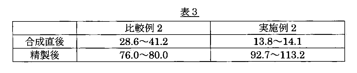
表3からわかるように、実施例2において陽極にアモルファスカーボン棒を使用して製造した粗製煤をチャンバの側壁内面から回収して精製した煤では、ラマン強度比(D/G)が92.7~113.2と非常に高く、純度が非常に高くなっている。これは、単位体積に占めるグラファイトが非常に少なくなった分だけ、不純物が非常に少なく、カーボンナノチューブの純度が非常に高くなったことを意味している。
また、グラファイト粉末(和光純薬工業株式会社製)に代えて、アモルファスカーボン棒に穴を開けるとともに角を落として八角形の棒に加工する際に生じた粉末を使用した以外は、比較例2と同様の混合粉末からなる金属触媒をアモルファスカーボン棒の穴に充填して陽極を作製した。
次に、作製した陽極を使用して、30.0A(電流密度1.01A/mm2)の電流を3分間、40.0A(電流密度1.34A/mm2)の電流を3分間、50.0A(電流密度1.68A/mm2)の電流を3分間、60.0A(電流密度2.01A/mm2)の電流を3分間、70.0A(電流密度2.35A/mm2)の電流を5分間流してアニール処理を行い、陽極と陰極を接触させた状態で80.0A(電流密度2.68A/mm2)の電流を流してアーク放電を行った以外は、比較例2と同様の方法により、合成した単層カーボンナノチューブを含む煤を回収した。なお、本実施例では、電流密度は電流値をロッドの断面積29.82mm2で割った値である。
このようにして回収された煤中には、単層カーボンナノチューブの他に不純物が含まれているので、比較例2と同様の方法により、不純物を除去して、精製された単層カーボンナノチューブを得た。
(実施例2および比較例2において陽極に使用した炭素棒の評価)
実施例2において陽極に使用したアモルファスカーボン棒と、比較例2において陽極に使用したグラファイト棒と、参考例としてのグラファイト粉末(和光純薬工業株式会社製)のX線回折(XRD)プロファイルをFig.7に示す。
理論的なグラファイトのXRDプロファイルでは、回折角度2θ=26.38°付近にピークが現れ、このピークは六方晶系グラファイトの(002)面に由来する。六方晶系グラファイトのC軸方向の平均面間隔、すなわち(002)面の平均面間隔dは、波長λをX線源として用いたCuKα線の0.1541nmとすると、Braggの式(d=λ/2sinθ)より0.3379nmになる。
Fig.7に示すように、参考例としてのグラファイト粉末および比較例2において陽極に使用したグラファイト棒のXRDプロファイルでは、それぞれ回折角度2θ=26.55°および2θ=26.48°にピークが現れている。また、結晶子が長周期にわたって発達しているので回折強度も大きい。そのため、Fig.7に示すように、それぞれ回折角度2θ=26.55°および2θ=26.48°に回折強度が大きいピークが現れている。これらの(002)面の平均面間隔dは、それぞれ0.3357nmおよび0.3366nmになり、理論的なグラファイトのXRDプロファイルの回折角度および(002)面の平均面間隔dと良く一致していることから、いずれもグラファイト結晶構造が高度に発達しているといえる。六方晶系グラファイトの(002)面の平均面間隔dよりも小さな値になっているのは、菱面体晶系グラファイトの回折角度が26.60°であり、(002)面の平均面間隔dが0.3349nmであることから、菱面体晶系グラファイトが存在するためであると考えられる。これは、高度に黒鉛構造が発達したグラファイト粉末が微細化された際に、応力が作用して菱面体晶系グラファイトに構造が転移するためであると考えられる。
一方、実施例2において陽極に使用したアモルファスカーボン棒のXRDプロファイルでは、Fig.7に示すように、それぞれ回折角度2θ=24.99°および24.55°に回折強度が低いブロードなピークが現れている。これらの(002)面の平均面間隔dは、それぞれ0.3563nmおよび0.3626nmになる。実施例2において陽極に使用したアモルファスカーボン棒では、グラファイト粉末および比較例2において陽極に使用したグラファイト棒と比べて、ピークの回折角度が低角側にシフトし、(002)面の平均面間隔dが大きな値になっている。このように回折強度が低いブロードなピークになり、ピークの回折角度が低角側にシフトするのは、平行に積層した炭素六角網平面の枚数が少なく、その積層に乱れが大きいためである。また、(002)面の平均面間隔dが大きな値になっているのは、アモルファスカーボンでは炭素六角網平面が規則正しい層構造を持たない乱層構造をとっているためである。
また、実施例2において陽極に使用したアモルファスカーボン棒と、比較例2において陽極に使用したグラファイト棒と、参考例としてのグラファイト粉末(和光純薬工業株式会社製)を大気中において昇温速度5℃/分で昇温させたときの質量減少百分率曲線をFig.8に示す。
炭素物質が酸素と反応するとCOやCO2が生成するので、大気中における炭素材料の質量熱分析によって、炭素物質がどの温度で酸素と反応するかを調べることができる。一般に、グラファイトでは、酸化開始温度は700℃であるが、低黒鉛化度の炭素材料では、その黒鉛化度にもよるが酸化開始温度は400~600℃である。このように低黒鉛化度の炭素材料で酸化開始温度が低くなるのは、グラファイト構造ではない乱層構造の方が、酸素との反応場であるグラフィンのエッジが多数露出しており、また、数nmオーダーのグラフィンであるので、熱的に不安定な構造状態になるからである。
Fig.8に示すように、参考例としてのグラファイト粉末および比較例2において陽極に使用したグラファイト棒では、約600℃から質量減少が認められる。一方、実施例2において陽極に使用したアモルファスカーボン棒では、約500℃から質量減少が認められる。これらの結果からも、実施例2において陽極に使用したアモルファスカーボン棒が、規則正しい層構造を持たない乱層構造から構成される低黒鉛化度の炭素棒であることがわかる。
(実施例2および比較例2において製造した単層カーボンナノチューブの評価)
実施例2において陽極にアモルファスカーボン棒を使用して製造した粗製煤と、比較例2において陽極にグラファイト棒を使用して製造した粗製煤をそれぞれチャンバの天板から回収した合成直後(精製前)の煤のX線回折(XRD)プロファイルをFig.9Aに示し、これらのアモルファスカーボン棒およびグラファイト棒を使用して製造した粗製煤をそれぞれチャンバの側壁内面から回収した合成直後(精製前)の煤のX線回折(XRD)プロファイルをFig.9Bに示す。また、実施例2において陽極にアモルファスカーボン棒を使用して製造した粗製煤と、比較例2において陽極にグラファイト棒を使用して製造した粗製煤をチャンバの天板から回収して精製した煤のX線回折(XRD)プロファイルをFig.10Aに示し、これらのアモルファスカーボン棒およびグラファイト棒を使用して製造した粗製煤をそれぞれチャンバの側壁内面から回収して精製した煤のX線回折(XRD)プロファイルをFig.10Bに示す。
これらの図に示すように、比較例2において製造した粗製煤をチャンバの天板および側壁内面から回収した合成直後と精製後の煤のXRDプロファイルには、2θ=26.38°付近に六方晶系グラファイトの(002)面に由来する回折強度が大きいピークが現れており、回収した煤中にグラファイトが含まれているのは明らかである。なお、精製後にグラファイトのピーク強度が大きくなっているのは、カーボンナノチューブの純度が高くなる一方で、大気中において500℃で燃焼させてもグラファイトが酸化されずに残存し、体積当りに占めるグラファイトの濃度が大きくなったためである。
一方、これらの図に示すように、実施例2において陽極にアモルファスカーボン棒を使用して製造した粗製煤をチャンバの天板および側壁内面から回収した合成直後と精製後の煤のXRDプロファイルには、グラファイトのピーク(2θ=26.38°付近のピーク)が現れていない。なお、チャンバの天板および側壁内面から回収して精製した煤のXRDプロファイルには、2θ=26.19°付近と2θ=26.68°付近のピークが現れている。これらのピークは、アーク放電により生成された(金属触媒を覆う)グラファイトカプセルなどの僅かなグラファイトに由来するピークであると推測され、チャンバの天板および側壁内面から回収して精製した煤には、面間隔の異なる結晶子が混在していること、すなわち乱層構造のグラファイト系不純物と規則的積層構造のグラファイト系不純物が混在していることを示している。
また、チャンバの天板および側壁内面から回収した合成直後の煤のXRDプロファイルに現れていた金属触媒(FeとNi)由来のピーク(2θ=43.6°付近のピークと2θ=50.8°付近のピーク)は、精製後の煤のXRDプロファイルには観察されず、精製によって金属触媒が取り除かれていることがわかる。
また、実施例2において陽極にアモルファスカーボン棒を使用して製造した粗製煤と、比較例2において陽極にグラファイト棒を使用して製造した粗製煤をチャンバの側壁内面から回収した合成直後(精製前)の煤を走査電子顕微鏡(SEM)によって観察したところ、いずれのSEMでも約10~15nmの小さな金属触媒粒子と、その周りを覆うアモルファスカーボンと、繊維状の単層カーボンナノチューブが観察された。
また、実施例2において陽極にアモルファスカーボン棒を使用して製造した粗製煤と、比較例2において陽極にグラファイト棒を使用して製造した粗製煤をそれぞれチャンバの側壁内面から回収して精製した煤を走査電子顕微鏡(SEM)によって観察したところ、金属触媒粒子とアモルファスカーボンが除去されていることが観察され、単層カーボンナノチューブが高純度化されていることが確認された。比較例2において陽極にグラファイト棒を使用して製造した粗製煤をチャンバの側壁内面から回収して精製した煤のSEM写真では、グラファイト棒またはグラファイト粉末のSEM写真と良く似た形状の塊が観察された。この塊はスパッタにより混入した陽極の一部(グラファイトの塊)であると考えられる。また、実施例2において陽極にアモルファスカーボン棒を使用して製造した粗製煤をチャンバの側壁内面から回収して精製した煤のSEM写真では、その陽極に使用したアモルファスカーボン棒のSEM写真と良く似た形状の直径約30~150nmの粒子と直径約10nmの小さい粒子が観察された。直径約30~150nmの粒子は、陽極からのスパッタにより混入した粒子であると考えられ、直径約10nmの小さい粒子は、アーク放電により蒸発、昇華した原子状の炭素から生成したグラファイトであると考えられる。
また、実施例2において陽極にアモルファスカーボン棒を使用して製造した粗製煤と、比較例2において陽極にグラファイト棒を使用して製造した粗製煤をそれぞれチャンバの側壁内面から回収した合成直後(精製前)および精製後の煤のラマン散乱分光測定を行った。その結果、実施例2では、合成直後(精製前)および精製後の煤のラマン強度比(D/G)が、それぞれ13.8~14.1および92.7~113.2であり、比較例2では、合成直後(精製前)および精製後の煤のラマン強度比(D/G)が、それぞれ28.6~41.2および76.0~80.0であった。これらの結果を表3に示す。
Claims (20)
- アーク放電によりカーボンナノチューブを含む煤を生成した後、得られた煤を精製することによってカーボンナノチューブを製造する方法において、アーク放電の際にアモルファスカーボンを主成分とする陽極を使用することを特徴とする、カーボンナノチューブの製造方法。
- 前記アモルファスカーボンを主成分とする陽極が、アモルファスカーボンを50質量%以上含むことを特徴とする、請求項1に記載のカーボンナノチューブの製造方法。
- 前記アモルファスカーボンを主成分とする陽極が金属触媒を含むことを特徴とする、請求項1または2に記載のカーボンナノチューブの製造方法。
- 前記アモルファスカーボンを主成分とする陽極が、カーボンブラックとコールタールピッチの混合物を焼成して得られたアモルファスカーボン棒に形成された穴に金属触媒が充填された陽極であることを特徴とする、請求項1または2に記載のカーボンナノチューブの製造方法。
- 前記金属触媒がFeとNiとSを含む混合粉末からなることを特徴とする、請求項3または4に記載のカーボンナノチューブの製造方法。
- 前記精製が、前記カーボンナノチューブを含む煤を大気中において350℃以上の温度で加熱して燃焼酸化する第1の燃焼酸化工程を含むことを特徴とする、請求項1乃至5のいずれかに記載のカーボンナノチューブの製造方法。
- 前記精製が、前記第1の燃焼酸化工程で得られた煤を酸に浸して処理する第1の酸処理工程を含むことを特徴とする、請求項6に記載のカーボンナノチューブの製造方法。
- 前記精製が、前記第1の酸処理工程で得られた煤を大気中において前記第1の燃焼酸化工程の加熱温度以上且つ500℃以上の温度で加熱して燃焼酸化する第2の燃焼酸化工程を含むことを特徴とする、請求項7に記載のカーボンナノチューブの製造方法。
- 前記精製が、前記第2の燃焼酸化工程で得られた煤を酸に浸して処理する第2の酸処理工程を含むことを特徴とする、請求項8に記載のカーボンナノチューブの製造方法。
- 前記精製が、前記第2の酸処理工程で得られた煤を真空中において加熱する真空加熱処理工程を含むことを特徴とする、請求項9に記載のカーボンナノチューブの製造方法。
- 前記真空加熱処理工程の加熱温度が1000℃以上であることを特徴とする、請求項10に記載のカーボンナノチューブの製造方法。
- 前記カーボンナノチューブが単層カーボンナノチューブであることを特徴とする、請求項1乃至11のいずれかに記載のカーボンナノチューブの製造方法。
- ラマン散乱分光測定において、カーボンナノチューブ固有のラマンバンドであるGバンドのスペクトルの強度と、アモルファスカーボン由来のDバンドのスペクトルの強度の比(G/D比)が85~115であることを特徴とする、カーボンナノチューブ。
- 吸着気体としてH2またはD2を吹き付けて吸着させた後、昇温速度0.2K/sで昇温させて測定された昇温脱離スペクトルにおいて、温度19.0~22.0Kに半値幅1.0K以下のピークを有することを特徴とする、請求項13に記載のカーボンナノチューブ。
- 透過型電子顕微鏡(TEM)像において、100nm四方に1nm程度の欠陥が10個以下であることを特徴とする、請求項13または14に記載のカーボンナノチューブ。
- 前記カーボンナノチューブが単層カーボンナノチューブであることを特徴とする、請求項13乃至15のいずれかに記載のカーボンナノチューブ。
- アモルファスカーボンを主成分とすることを特徴とする、単層カーボンナノチューブ製造用陽極。
- 前記陽極がアモルファスカーボンを50質量%以上含むことを特徴とする、請求項17に記載の単層カーボンナノチューブ製造用陽極。
- 前記陽極が金属触媒を含むことを特徴とする、請求項17または18に記載の単層カーボンナノチューブ製造用陽極。
- 前記陽極がカーボンブラックとコールタールピッチの混合物を焼成して得られたアモルファスカーボン棒に形成された穴に金属触媒が充填された陽極であることを特徴とする、請求項17または18に記載の単層カーボンナノチューブ製造用陽極。
Priority Applications (3)
| Application Number | Priority Date | Filing Date | Title |
|---|---|---|---|
| US13/376,564 US8858909B2 (en) | 2009-06-11 | 2010-05-28 | Carbon nanotube and method for producing same |
| EP10786116.3A EP2431325B1 (en) | 2009-06-11 | 2010-05-28 | Process for producing carbon nanotubes |
| CN201080026367.0A CN102459073B (zh) | 2009-06-11 | 2010-05-28 | 碳纳米管及其制造方法 |
Applications Claiming Priority (4)
| Application Number | Priority Date | Filing Date | Title |
|---|---|---|---|
| JP2009139927 | 2009-06-11 | ||
| JP2009-139927 | 2009-06-11 | ||
| JP2010-116874 | 2010-05-21 | ||
| JP2010116874A JP5647435B2 (ja) | 2009-06-11 | 2010-05-21 | カーボンナノチューブおよびその製造方法 |
Publications (1)
| Publication Number | Publication Date |
|---|---|
| WO2010143585A1 true WO2010143585A1 (ja) | 2010-12-16 |
Family
ID=43308840
Family Applications (1)
| Application Number | Title | Priority Date | Filing Date |
|---|---|---|---|
| PCT/JP2010/059492 WO2010143585A1 (ja) | 2009-06-11 | 2010-05-28 | カーボンナノチューブおよびその製造方法 |
Country Status (5)
| Country | Link |
|---|---|
| US (1) | US8858909B2 (ja) |
| EP (1) | EP2431325B1 (ja) |
| JP (1) | JP5647435B2 (ja) |
| CN (1) | CN102459073B (ja) |
| WO (1) | WO2010143585A1 (ja) |
Cited By (1)
| Publication number | Priority date | Publication date | Assignee | Title |
|---|---|---|---|---|
| CN102602911A (zh) * | 2012-03-07 | 2012-07-25 | 上海交通大学 | 一种采用低压反应性气体可控性制备单壁碳纳米管的方法 |
Families Citing this family (24)
| Publication number | Priority date | Publication date | Assignee | Title |
|---|---|---|---|---|
| WO2010120581A1 (en) | 2009-04-17 | 2010-10-21 | Noyes Dallas B | Method for producing solid carbon by reducing carbon oxides |
| WO2013158156A1 (en) | 2012-04-16 | 2013-10-24 | Seerstone Llc | Methods and structures for reducing carbon oxides with non-ferrous catalysts |
| JP6242858B2 (ja) | 2012-04-16 | 2017-12-06 | シーアストーン リミテッド ライアビリティ カンパニー | 炭素を捕捉および隔離するため、ならびに廃ガスストリーム中の酸化炭素の質量を低減するための方法およびシステム |
| JP2015514669A (ja) | 2012-04-16 | 2015-05-21 | シーアストーン リミテッド ライアビリティ カンパニー | 二酸化炭素を還元することによって固体炭素を生成するための方法 |
| NO2749379T3 (ja) | 2012-04-16 | 2018-07-28 | ||
| JP6379085B2 (ja) | 2012-04-16 | 2018-08-22 | シーアストーン リミテッド ライアビリティ カンパニー | 炭素酸化物を含有するオフガスを処理するための方法 |
| US9896341B2 (en) | 2012-04-23 | 2018-02-20 | Seerstone Llc | Methods of forming carbon nanotubes having a bimodal size distribution |
| US10815124B2 (en) | 2012-07-12 | 2020-10-27 | Seerstone Llc | Solid carbon products comprising carbon nanotubes and methods of forming same |
| WO2014011631A1 (en) | 2012-07-12 | 2014-01-16 | Seerstone Llc | Solid carbon products comprising carbon nanotubes and methods of forming same |
| MX2015000580A (es) | 2012-07-13 | 2015-08-20 | Seerstone Llc | Metodos y sistemas para formar productos de carbono solido y amoniaco. |
| US9779845B2 (en) | 2012-07-18 | 2017-10-03 | Seerstone Llc | Primary voltaic sources including nanofiber Schottky barrier arrays and methods of forming same |
| US9650251B2 (en) | 2012-11-29 | 2017-05-16 | Seerstone Llc | Reactors and methods for producing solid carbon materials |
| WO2014151898A1 (en) | 2013-03-15 | 2014-09-25 | Seerstone Llc | Systems for producing solid carbon by reducing carbon oxides |
| US10086349B2 (en) | 2013-03-15 | 2018-10-02 | Seerstone Llc | Reactors, systems, and methods for forming solid products |
| US9783416B2 (en) | 2013-03-15 | 2017-10-10 | Seerstone Llc | Methods of producing hydrogen and solid carbon |
| EP3129321B1 (en) | 2013-03-15 | 2021-09-29 | Seerstone LLC | Electrodes comprising nanostructured carbon |
| EP3113880A4 (en) | 2013-03-15 | 2018-05-16 | Seerstone LLC | Carbon oxide reduction with intermetallic and carbide catalysts |
| US11752459B2 (en) | 2016-07-28 | 2023-09-12 | Seerstone Llc | Solid carbon products comprising compressed carbon nanotubes in a container and methods of forming same |
| CN108808025A (zh) * | 2018-07-04 | 2018-11-13 | 南京邮电大学 | 一种碳纳米管负载氧化铁氧还原催化剂的制备方法 |
| JP7098449B2 (ja) * | 2018-07-11 | 2022-07-11 | 国立大学法人東北大学 | カーボンナノチューブ含有スズドープ酸化インジウム膜およびその製造方法 |
| JP7098448B2 (ja) * | 2018-07-11 | 2022-07-11 | 国立大学法人東北大学 | カーボンナノチューブ含有スズドープ酸化インジウム膜およびその製造方法 |
| CN110589805B (zh) * | 2019-10-30 | 2021-02-19 | 山东大展纳米材料有限公司 | 一种电弧活化碳纳米管后经cvd制备碳气凝胶的装置及方法 |
| CN114014300A (zh) * | 2021-11-24 | 2022-02-08 | 深圳市飞墨科技有限公司 | 碳纳米管及其纯化方法 |
| CN114890407B (zh) * | 2022-05-31 | 2023-09-19 | 江西铜业技术研究院有限公司 | 一种等离子体制备单壁碳纳米管的装置和方法 |
Citations (4)
| Publication number | Priority date | Publication date | Assignee | Title |
|---|---|---|---|---|
| JP2003081616A (ja) * | 2001-07-05 | 2003-03-19 | Honda Motor Co Ltd | 単層カーボンナノチューブの精製方法 |
| JP2004210555A (ja) | 2002-12-27 | 2004-07-29 | Hitachi Powdered Metals Co Ltd | カーボンナノチューブの製造方法 |
| JP2005022902A (ja) * | 2003-06-30 | 2005-01-27 | Toyo Tanso Kk | 金属−炭素複合材料 |
| JP2006016282A (ja) | 2004-07-05 | 2006-01-19 | Shinzo Suzuki | 単層カーボンナノチューブの製造法 |
Family Cites Families (7)
| Publication number | Priority date | Publication date | Assignee | Title |
|---|---|---|---|---|
| CN1101335C (zh) * | 1999-06-16 | 2003-02-12 | 中国科学院金属研究所 | 一种大量制备单壁纳米碳管的氢弧放电方法 |
| US6752977B2 (en) * | 2001-02-12 | 2004-06-22 | William Marsh Rice University | Process for purifying single-wall carbon nanotubes and compositions thereof |
| US7008605B1 (en) * | 2001-11-08 | 2006-03-07 | The United States Of America As Represented By The Administrator Of The National Aeronautics And Space Administration | Method for manufacturing high quality carbon nanotubes |
| JP3997930B2 (ja) * | 2003-02-27 | 2007-10-24 | 富士ゼロックス株式会社 | カーボンナノチューブの製造装置および製造方法 |
| CN1299980C (zh) * | 2004-06-15 | 2007-02-14 | 南开大学 | 单壁碳纳米管的电弧合成方法 |
| CN100522804C (zh) * | 2005-10-18 | 2009-08-05 | 南开大学 | 一种电弧法合成可控单壁碳纳米管的方法 |
| US7955663B2 (en) * | 2006-12-04 | 2011-06-07 | Council Of Scientific And Industrial Research | Process for the simultaneous and selective preparation of single-walled and multi-walled carbon nanotubes |
-
2010
- 2010-05-21 JP JP2010116874A patent/JP5647435B2/ja active Active
- 2010-05-28 CN CN201080026367.0A patent/CN102459073B/zh active Active
- 2010-05-28 WO PCT/JP2010/059492 patent/WO2010143585A1/ja active Application Filing
- 2010-05-28 US US13/376,564 patent/US8858909B2/en active Active
- 2010-05-28 EP EP10786116.3A patent/EP2431325B1/en active Active
Patent Citations (4)
| Publication number | Priority date | Publication date | Assignee | Title |
|---|---|---|---|---|
| JP2003081616A (ja) * | 2001-07-05 | 2003-03-19 | Honda Motor Co Ltd | 単層カーボンナノチューブの精製方法 |
| JP2004210555A (ja) | 2002-12-27 | 2004-07-29 | Hitachi Powdered Metals Co Ltd | カーボンナノチューブの製造方法 |
| JP2005022902A (ja) * | 2003-06-30 | 2005-01-27 | Toyo Tanso Kk | 金属−炭素複合材料 |
| JP2006016282A (ja) | 2004-07-05 | 2006-01-19 | Shinzo Suzuki | 単層カーボンナノチューブの製造法 |
Non-Patent Citations (2)
| Title |
|---|
| PARK Y S ET AL.: "Low pressure synthesis of single-walled carbon nanotubes by arc discharge", SYNTH MET, vol. 126, no. 2-3, 14 February 2002 (2002-02-14), pages 245 - 251, XP008148944 * |
| S. IWATA ET AL.: "Novel Method to Evaluate the Carbon Network of Single-Walled Carbon Nanotubes by Hydrogen Physisorption", THE JOURNAL OF PHYSICAL CHEMISTRY C LETTERS, vol. 111, 22 September 2007 (2007-09-22), pages 14937 - 14941, XP008148946 * |
Cited By (1)
| Publication number | Priority date | Publication date | Assignee | Title |
|---|---|---|---|---|
| CN102602911A (zh) * | 2012-03-07 | 2012-07-25 | 上海交通大学 | 一种采用低压反应性气体可控性制备单壁碳纳米管的方法 |
Also Published As
| Publication number | Publication date |
|---|---|
| JP2011016711A (ja) | 2011-01-27 |
| EP2431325A4 (en) | 2016-04-27 |
| EP2431325B1 (en) | 2019-12-04 |
| CN102459073B (zh) | 2014-05-14 |
| EP2431325A1 (en) | 2012-03-21 |
| JP5647435B2 (ja) | 2014-12-24 |
| US20120083408A1 (en) | 2012-04-05 |
| US8858909B2 (en) | 2014-10-14 |
| CN102459073A (zh) | 2012-05-16 |
Similar Documents
| Publication | Publication Date | Title |
|---|---|---|
| JP5647435B2 (ja) | カーボンナノチューブおよびその製造方法 | |
| JP5424481B2 (ja) | カーボンナノチューブを含んだ炭素材料の精製方法 | |
| US7799308B2 (en) | Ultra-fine fibrous carbon and preparation method thereof | |
| Zhu et al. | The design and construction of 3D rose-petal-shaped MoS 2 hierarchical nanostructures with structure-sensitive properties | |
| Wu et al. | Large-scale synthesis of high-quality graphene sheets by an improved alternating current arc-discharge method | |
| JP5253943B2 (ja) | 導電性材料およびその製造方法 | |
| JP5599204B2 (ja) | カーボンナノチューブ集合体及びその製造方法 | |
| KR101105473B1 (ko) | 신규한 구조의 탄소계 나노복합체 및 이의 제조방법 | |
| JP2008069015A (ja) | 薄片炭素粒子及びその製造方法 | |
| Wang et al. | Preparation and electrochemical performance of ultra-short carbon nanotubes | |
| JP4761346B2 (ja) | 2層カーボンナノチューブ含有組成物 | |
| Osikoya et al. | Synthesis, characterization and adsorption studies of chlorine–doped carbon nanotubes | |
| Fedorovskaya et al. | Effect of oxidative treatment on the electrochemical properties of aligned multi-walled carbon nanotubes | |
| JP5330034B2 (ja) | カーボンナノチューブの評価方法 | |
| JP5330035B2 (ja) | カーボンナノチューブおよびその製造方法 | |
| JP2007015914A (ja) | カーボンナノチューブの製造方法 | |
| JP3914179B2 (ja) | カーボンナノファイバーの構造制御方法 | |
| Karmakar et al. | A new approach towards improving the quality and yield of arc-generated carbon nanotubes | |
| Dadsetan et al. | Carbon film produced from microwave-driven methane pyrolysis | |
| KR100514186B1 (ko) | 고비표면적 탄소재 | |
| Nakajima et al. | Structure, chemical bonding and electrochemical behavior of heteroatom-substituted carbons prepared by arc discharge and chemical vapor deposition | |
| KR100726368B1 (ko) | 섬유상 나노탄소 | |
| JP5321880B2 (ja) | ナノ炭素材料複合体 | |
| Raghubanshi et al. | Synthesis of carbon nanostructures using hydrogen storage alloys as catalysts | |
| Krasil’nikov et al. | Precursor Synthesis and Properties of Nanodispersed Tungsten Carbide and WC: nC Nanocomposites |
Legal Events
| Date | Code | Title | Description |
|---|---|---|---|
| WWE | Wipo information: entry into national phase |
Ref document number: 201080026367.0 Country of ref document: CN |
|
| 121 | Ep: the epo has been informed by wipo that ep was designated in this application |
Ref document number: 10786116 Country of ref document: EP Kind code of ref document: A1 |
|
| WWE | Wipo information: entry into national phase |
Ref document number: 2010786116 Country of ref document: EP |
|
| WWE | Wipo information: entry into national phase |
Ref document number: 13376564 Country of ref document: US |
|
| NENP | Non-entry into the national phase |
Ref country code: DE |