WO2010114011A1 - 吸収性物品及び吸収性物品の製造方法 - Google Patents
吸収性物品及び吸収性物品の製造方法 Download PDFInfo
- Publication number
- WO2010114011A1 WO2010114011A1 PCT/JP2010/055823 JP2010055823W WO2010114011A1 WO 2010114011 A1 WO2010114011 A1 WO 2010114011A1 JP 2010055823 W JP2010055823 W JP 2010055823W WO 2010114011 A1 WO2010114011 A1 WO 2010114011A1
- Authority
- WO
- WIPO (PCT)
- Prior art keywords
- absorbent article
- region
- absorbent
- absorber
- weight area
- Prior art date
Links
Images


Classifications
-
- A—HUMAN NECESSITIES
- A61—MEDICAL OR VETERINARY SCIENCE; HYGIENE
- A61F—FILTERS IMPLANTABLE INTO BLOOD VESSELS; PROSTHESES; DEVICES PROVIDING PATENCY TO, OR PREVENTING COLLAPSING OF, TUBULAR STRUCTURES OF THE BODY, e.g. STENTS; ORTHOPAEDIC, NURSING OR CONTRACEPTIVE DEVICES; FOMENTATION; TREATMENT OR PROTECTION OF EYES OR EARS; BANDAGES, DRESSINGS OR ABSORBENT PADS; FIRST-AID KITS
- A61F13/00—Bandages or dressings; Absorbent pads
- A61F13/15—Absorbent pads, e.g. sanitary towels, swabs or tampons for external or internal application to the body; Supporting or fastening means therefor; Tampon applicators
- A61F13/45—Absorbent pads, e.g. sanitary towels, swabs or tampons for external or internal application to the body; Supporting or fastening means therefor; Tampon applicators characterised by the shape
- A61F13/47—Sanitary towels, incontinence pads or napkins
- A61F13/475—Sanitary towels, incontinence pads or napkins characterised by edge leakage prevention means
- A61F13/4751—Sanitary towels, incontinence pads or napkins characterised by edge leakage prevention means the means preventing fluid flow in a transversal direction
- A61F13/4752—Sanitary towels, incontinence pads or napkins characterised by edge leakage prevention means the means preventing fluid flow in a transversal direction the means being an upstanding barrier
- A61F13/4753—Sanitary towels, incontinence pads or napkins characterised by edge leakage prevention means the means preventing fluid flow in a transversal direction the means being an upstanding barrier the barrier being not integral with the topsheet or backsheet
-
- A—HUMAN NECESSITIES
- A61—MEDICAL OR VETERINARY SCIENCE; HYGIENE
- A61F—FILTERS IMPLANTABLE INTO BLOOD VESSELS; PROSTHESES; DEVICES PROVIDING PATENCY TO, OR PREVENTING COLLAPSING OF, TUBULAR STRUCTURES OF THE BODY, e.g. STENTS; ORTHOPAEDIC, NURSING OR CONTRACEPTIVE DEVICES; FOMENTATION; TREATMENT OR PROTECTION OF EYES OR EARS; BANDAGES, DRESSINGS OR ABSORBENT PADS; FIRST-AID KITS
- A61F13/00—Bandages or dressings; Absorbent pads
- A61F13/15—Absorbent pads, e.g. sanitary towels, swabs or tampons for external or internal application to the body; Supporting or fastening means therefor; Tampon applicators
- A61F13/45—Absorbent pads, e.g. sanitary towels, swabs or tampons for external or internal application to the body; Supporting or fastening means therefor; Tampon applicators characterised by the shape
- A61F13/47—Sanitary towels, incontinence pads or napkins
- A61F13/476—Sanitary towels, incontinence pads or napkins characterised by encircling the crotch region of the undergarment
Definitions
- the present invention relates to an absorbent article and a method for manufacturing the absorbent article, in which a joined portion in which at least a surface sheet and an absorbent body are joined is formed.
- absorbent articles such as sanitary napkins and panty liners include a liquid-permeable top sheet, a liquid-impermeable back sheet, and an absorber provided between the top sheet and the back sheet.
- a joint is formed by applying pressure (for example, embossing) in the thickness direction of the absorbent article.
- the joint portion extends in the front-rear direction corresponding to the direction from the wearer's front side (abdomen side) to the back side (back side), that is, in the longitudinal direction of the absorbent article. According to this technique, the joint portion can block the body fluid of the wearer and prevent the body fluid from leaking from the absorbent article (so-called side leakage).
- the conventional absorbent article described above has the following problems. That is, since a junction part is formed when a pressure is applied to the thickness direction of an absorptive article, it will become hard compared with the circumference of a junction part. That is, since the joining portion extends along the longitudinal direction of the absorbent article, the absorbent article itself becomes hard with respect to the longitudinal direction as the joining portion becomes hard.
- the absorbent article is difficult to bend from the front side to the back side of the wearer, and is difficult to fit the wearer. Therefore, there is a problem that the wearing feeling to the wearer is deteriorated and a side leakage occurs.
- the absorbent article includes a liquid-permeable top sheet, a liquid-impermeable back sheet, and an absorber provided between the top sheet and the back sheet.
- the absorbent article is formed with a joint portion where at least the topsheet and the absorber are joined.
- the absorbent body includes a first region in which the absorbent material constituting the absorbent body has a predetermined weighing, and a second region in which the absorbent material is weighed less than the first region, and the second region includes: It extends along the longitudinal direction of the absorbent article, is sandwiched between the first regions in the width direction of the absorbent article, and the joint is formed in the second region.
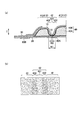
- FIG. 1 is a plan view showing an absorbent article 1 according to the first embodiment.
- FIG. 2 is a cross-sectional view (AA cross-sectional view of FIG. 1) showing the absorbent article 1 according to the first embodiment.
- Fig.3 (a) is an expanded sectional view which shows the absorbent article 1 which concerns on 1st Embodiment
- FIG.3 (b) is a figure for demonstrating the fabric weight of the absorber 40 which concerns on 1st Embodiment. is there.
- Drawing 4 is a figure for explaining the manufacturing method of the absorptive article concerning a 1st embodiment.
- FIG. 5 is a perspective view showing the absorber stacking apparatus 500 according to the first embodiment.
- FIG. 6C are views showing the recess 510 according to the first embodiment.
- FIG. 7 is a plan view showing an absorbent article 1A according to the second embodiment.
- FIG. 8A to FIG. 8C are cross-sectional views showing an absorbent article 1A according to the second embodiment.
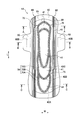
- FIG. 9 is a top view which shows the absorbent article 1B which concerns on the example of a change (the 1).
- FIG. 10 is a three-view diagram showing only the absorbent body 40 of the absorbent article 1B according to the modified example (part 1).
- FIG. 11 is a top view which shows the absorbent article 1B which concerns on the example of a change (the 2).
- FIG. 12 is a three-view diagram illustrating only the absorbent body 40 of the absorbent article 1B according to the modified example (part 2).
- FIG. 1 is a plan view showing an absorbent article 1 according to the first embodiment.
- FIG. 2 is a cross-sectional view (AA cross-sectional view of FIG. 1) showing the absorbent article 1 according to the first embodiment.
- the absorbent article 1 is a sanitary napkin.
- the absorbent article 1 is the front-back direction (henceforth the longitudinal direction L of the absorbent article 1) corresponding to the direction which goes to a back side (back side) from a wearer's front side (abdominal side). ) With a vertically long shape.
- the absorbent article 1 includes a top sheet 10, a back sheet 20, a side sheet 30, and an absorber 40. Moreover, the wing part 50, the adhesion part 60, and the junction part 70 are formed in the absorbent article 1.
- FIG. 1 is a diagrammatic representation of the absorbent article 1.
- the top sheet 10 is provided on the side in contact with the wearer's skin.
- the top sheet 10 is formed of a liquid-permeable sheet such as an air-through nonwoven fabric (for example, polyethylene terephthalate and polyethylene).
- the back sheet 20 is provided closer to the non-wearer than the top sheet 10.
- the back sheet 20 is formed of a liquid-impermeable sheet such as a waterproof film (for example, polyethylene).
- the side sheet 30 is provided outside the width direction W perpendicular to the longitudinal direction L of the absorbent article 1 with respect to the top sheet 10.
- the side sheet 30 is formed of a liquid-permeable sheet such as a spunbond nonwoven fabric (for example, polypropylene and polyethylene).
- the absorber 40 is provided between the top sheet 10 and the back sheet 20.
- the absorber 40 is formed by coating an absorbent 40A made of a mixed powder such as pulverized pulp or a superabsorbent polymer with a coating 40B such as a tissue. The details of the absorber 40 will be described later.
- the top sheet 10, the back sheet 20, the side sheet 30, and the absorber 40 described above are bonded to each other by an adhesive (for example, hot melt) or heat fusion.
- the wing part 50 is formed by extending the back sheet 20 and the side sheet 30 beyond the absorbent body 40 toward the outside in the width direction W of the absorbent article 1.
- the adhesive part 60 is formed of an adhesive member (for example, hot melt) that can be stopped by shorts worn by the wearer.
- the adhesive part 60 is provided on the surface on the opposite side of the top sheet 10 in the back sheet 20.
- the adhesive part 60 has a long adhesive part 60A and a short adhesive part 60B.
- the long adhesive portion 60 ⁇ / b> A extends along the longitudinal direction L of the absorbent article 1.
- the short adhesive part 60B is shorter than the long adhesive part 60A, and is provided in a part constituting the wing part 50 of the back sheet 20.
- the joining portion 70 pressure is applied to at least the top sheet 10 and the absorber 40 in the thickness direction T of the absorbent article 1 (for example, embossing is performed), and the top sheet 10 and the absorbent body 40 are joined. Formed by.
- the joint portion 70 has a vertically long ring shape along the longitudinal direction L of the absorbent article 1. Specifically, in the plan view of the absorbent article 1, the joining portion 70 has a large annular portion 70A having the largest annular shape and an annular shape smaller than the large annular portion 70A in a region surrounded by the large annular portion 70A. The middle annular portion 70B and a small annular portion 70C having an annular shape smaller than the middle annular portion 70B in a region surrounded by the middle annular portion 70B.
- the joint portion 70 is formed in a low weight area 42 (first low weight area 421) of the absorber 40 described later.
- FIG.3 (a) is an expanded sectional view which shows the absorbent article 1 which concerns on 1st Embodiment
- FIG.3 (b) is a figure for demonstrating the fabric weight of the absorber 40 which concerns on 1st Embodiment. is there.
- the absorber 40 is formed by an absorbent material 40A that absorbs the body fluid of the wearer and a covering material 40B that covers the absorbent material 40A.
- the absorber 40 has a high weight area 41 (first area) and a low weight area 42 (second area) provided between the high weight areas 41.
- the high weight area 41 indicates an area other than the low weight area 42.
- the high basis weight area 41 has a predetermined weight (so-called basis weight (weight per unit area (g / m 2 ))) of the absorbent 40A constituting the absorber 40.
- the high basis weight area 41 is a low basis weight area 42.
- the absorbent material 40A has more predetermined weight per unit area.
- the high basis weight area 41 is formed to be thinner than the thick part 41C and the thick part 41C in the width direction W center and the longitudinal direction L center of the absorbent article 1, and the absorbent article than the thick part 41C. 1 and the thin portion 41S located outside the width direction W.
- the low basis weight region 42 extends along the longitudinal direction L of the absorbent article 1 and also extends along the width direction W of the absorbent article 1 (see FIG. 1).
- the low weight area 42 overlaps the long adhesive portion 60 ⁇ / b> A of the adhesive portions 60 with respect to the thickness direction T of the absorbent article 1. That is, the joint 70 described above also overlaps the long adhesive portion 60 ⁇ / b> A with respect to the thickness direction T of the absorbent article 1.
- the low basis weight region 42 has a vertically long ring shape along the longitudinal direction L of the absorbent article 1.
- the low weight area 42 has a large annular portion 42A having the largest annular shape in a plan view of the absorbent article 1 and an annular shape smaller than the large annular portion 42A in the region surrounded by the large annular portion 42A.
- An intermediate annular portion 42B is formed, and a small annular portion 42C that is smaller than the intermediate annular portion 42B in a region surrounded by the intermediate annular portion 42B (see FIG. 1).
- the low weight area 42 is sandwiched between the high weight areas 41 in the longitudinal direction L and the width direction W of the absorbent article 1 because the high weight areas 41 indicate areas other than the low weight areas 42 as described above. Provided.
- the low basis weight area 42 has a smaller amount of the absorbent material 40A than the high weight area 41.
- the low weight area 42 includes a first low weight area 421 and a second low weight area 422 as shown in FIG.
- the joint 70 described above is formed in the first low weight area 421 by applying pressure to at least the top sheet 10 and the absorber 40. On the other hand, no pressure is applied to the second low weight area 422, and the joint portion 70 is not formed.
- the joining portion 70 pressure is applied to at least the top sheet 10 and the absorber 40 in the thickness direction T of the absorbent article 1 (for example, embossing is performed), and the top sheet 10 and the absorbent body 40 are joined. Formed by.
- the width (W 1) orthogonal to the extending direction of the second low weight area 422 is equal to or greater than the width (W 2) orthogonal to the extending direction of the joint portion 70.
- the width (W1) is wider than the width (W2)
- the density of the high weight area 41 mass per unit volume (g / cm 3 ))
- the density of the first low weight area 421 is “ Assuming that the density of X ′ and the second low weight area 422 is “Y”, the relationship X>Z> Y is satisfied.
- Drawing 4 is a figure for explaining the manufacturing method of the absorptive article concerning a 1st embodiment.
- the manufacturing method of an absorbent article includes an absorbent material stacking step S1 (step A), a covering material folding step S2, a covering material joining step S3, an absorber cutting step S4, and an absorber stacking. It includes a step S5, a joining portion forming step S6 (step B), a back sheet pasting step S7, an article outer shape joining step S8, and an article outer shape cutting step S9.
- the absorbent material stacking step S1 mixed powders (not shown) such as pulverized pulp and superabsorbent polymer are collected and the absorbent material 40A is molded.
- the above-mentioned high weight area 41 and the low weight area 42 are formed in the absorber 40 by the absorber lamination apparatus 500 described later.
- the low basis weight area 42 is formed along the longitudinal direction L of the absorbent article 1, and the low basis area 42 is formed so as to be sandwiched between the high basis weight areas 41 in at least the width direction W of the absorbent article 1.
- the molded absorbent material 40A is laminated at a predetermined interval on a continuous body 140 of a covering material such as a tissue that is continuously conveyed.
- both side edges 141 in the intersecting direction CD intersecting the transport direction MD of the covering material continuous body 140 are folded back onto the absorbent material 40A.
- the covering material joining step S3 pressure is applied in the thickness direction T to the continuous body 140 of the covering material that covers the absorbent material 40A at predetermined intervals so as to correspond to the size of the absorbent body 40 of one product (for example, embossing) To be joined.
- the continuous body 140 of the covering material covering the absorbent material 40A at predetermined intervals is cut according to the size of the absorbent body 40 of one product.
- the absorbent body 40 cut in the absorbent body cutting step S4 is stacked on the continuous body 110 of the top sheet to which the continuous body 130 of side sheets to be continuously conveyed is attached.
- an adhesive for example, hot melt is applied onto the continuous body 110 of the top sheet.
- the joined portion 70 is formed by joining the continuous body 110 of the topsheet and the absorber 40. At this time, the joint portion 70 is formed in the low weight area 42.
- the back sheet continuous body 120 is pasted on the top sheet continuous body 110 and the side sheet continuous body 130.
- the absorber 40 is provided between the continuous body 110 of the top sheet and the continuous body 120 of the back sheet.
- an adhesive for example, hot melt
- the thickness of the continuous body 110 of the top sheet and the continuous body 120 of the back sheet, the continuous body 130 of the side sheet, and the continuous body 120 of the back sheet is adjusted so as to correspond to the external shape of the absorbent article 1.
- Each is joined by applying pressure (eg, embossing) in the direction T.
- the topsheet continuous body 110, the backsheet continuous body 120, and the sidesheet continuous body 130 are cut so as to correspond to the outer shape of the absorbent article 1. Thereby, the absorbent article 1 is manufactured.
- FIG. 5 is a perspective view showing the absorber stacking apparatus 500 according to the first embodiment.
- FIG. 6A is a perspective view showing the recess 510 according to the first embodiment
- FIG. 6B is a cross-sectional view in the width direction showing the recess 510 according to the first embodiment (of FIG. 6A).
- FIG. 6C is a longitudinal sectional view showing the recess 510 according to the first embodiment (BB sectional view of FIG. 6A).
- the absorber stacking apparatus 500 molds the absorbent material 40 ⁇ / b> A from the mixed powder ejected by the ejector (not shown) while rotating around the shaft core 501. Moreover, the absorbent body laminating apparatus 500 stacks the molded absorbent material 40A at a predetermined interval on the continuous body 140 of the covering material that is continuously conveyed.
- a concave portion 510 for collecting the mixed powder and molding the absorbent 40A is formed on the outer peripheral surface of the absorber stacking apparatus 500.
- a plurality of mesh-like suction holes 511A for sucking the mixed powder are provided in the bottom portion 511 of the recess 510.
- the recess 510 is constituted by a deep portion 510A and a shallow portion 510B.
- the deep portion 510A corresponds to the thick portion 41C. That is, the deep portion 510A corresponds to the center of the absorbent article 1, the width direction W, and the longitudinal direction L.
- the shallow portion 510B corresponds to the thin portion 41S and is shallower than the deep portion 510A.
- a convex portion 520 corresponding to the low weight area 42 is formed on the bottom portion 511 of the concave portion 510.
- the convex part 520 has a high convex part 520A and a low convex part 520B.
- the high convex portion 520A is formed in the deep portion 510A.
- the height (H1) of the high convex portion 520A is lower than the depth (D1) of the deep portion 510A.
- the low convex portion 520B is formed in the shallow portion 510B and is lower than the high convex portion 520A.
- the height (H2) of the low convex portion 520B is lower than the depth (D2) of the shallow portion 510B.
- the joint portion 70 is formed in the low weight area 42 (first low weight area 421) in which the weighing of the absorbent 40A is smaller than that of the high weight area 41.
- the joint portion 70 is formed in the low weight area 42 that extends along the longitudinal direction L of the absorbent article 1. According to this, even if a pressure is applied to the low weight area 42 in the thickness direction T of the absorbent article 1, it does not become harder than the periphery of the joint portion 70. That is, the absorbent article 1 does not become hard with respect to the longitudinal direction L. For this reason, the absorbent article 1 becomes easy to bend (becomes flexible) from the wearer's front side to the back side, and is easy to fit the wearer. Therefore, it is possible to prevent side leakage more reliably without deteriorating the wearing feeling to the wearer.
- the weighing (weight per unit area) of the absorbent is increased in order to secure the absorption capacity.
- the joining part 70 is provided in the absorbent article 1 with a large amount of absorbent material, the absorbent article 1 tends to become harder.
- the absorbent article 1 can be kept flexible and it becomes easy to adapt to a wearer.
- the absorber 40 includes a high weight area 41 and a low weight area 42. According to this, compared with the case where the absorber 40 is formed only by the high basis weight area
- the low weight area 42 extends along the width direction W of the absorbent article 1 in addition to the longitudinal direction L of the absorbent article 1. That is, the joining part 70 is also formed along the width direction W of the absorbent article 1. For this reason, it can prevent that the bodily fluid from a wearer spread
- the width (W1) orthogonal to the extending direction of the low weight area 42 is equal to or greater than the width (W2) orthogonal to the extending direction of the joint portion 70.
- the width (W1) is preferably wider than the width (W2). That is, the density (mass per unit volume (g / cm 3 )) of the high weight area 41 is “Z”, the density of the first low weight area 421 is “X”, and the density of the second low weight area 422 is “Y”. Then, the relationship X>Z> Y is satisfied. According to this, the body fluid absorbed in the high weight area 41 can be blocked by the second low weight area 422.
- the joining part 70 in the low weight area 42 is stable. If the width (W1) is narrower than the width (W2), the joint portion 70 is formed in the high weight area 41, and the joint portion 70 may become hard.
- the low weight area 42 is softer than the high weight area 41 because the weighing of the absorbent 40A is smaller than the high weight area 41. Thereby, the absorber 40 becomes easy to drown in the low weight area 42.
- the low weight area 42 is displaced from the long adhesive portion 60A, a space is formed between the shorts and the absorbent article 1 due to the movement of the wearer, and the low weight area 42 of the absorbent body 40 is easily drowned. End up.
- the low weight area 42 overlaps the long adhesive portion 60 ⁇ / b> A of the adhesive portions 60 with respect to the thickness direction T of the absorbent article 1. That is, the joint 70 described above also overlaps the long adhesive portion 60 ⁇ / b> A with respect to the thickness direction T of the absorbent article 1.
- region 42 which overlaps with 60 A of long adhesion parts is fixed to shorts. For this reason, it becomes possible for the low weight area 42, which is supposed to be drowned, to move with the shorts in accordance with the movement of the wearer (especially the movement of the crotch), and to prevent the absorber 40 from drowning in the low weight area 42. it can.
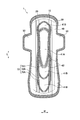
- FIG. 7 is a plan view showing an absorbent article 1A according to the second embodiment.
- FIG. 8A is a cross-sectional view (AA cross-sectional view of FIG. 7) showing an absorbent article 1A according to the second embodiment, and
- FIG. 8B is an absorbent article according to the second embodiment.
- FIG. 8C is a cross-sectional view (CC cross-sectional view of FIG. 7) showing the absorbent article 1A according to the second embodiment. is there.
- symbol is attached
- the absorbent article 1 includes the top sheet 10, the back sheet 20, the side sheet 30, and the absorber 40.
- 1 A of absorbent articles are provided with the leak-proof part 80 formed when the side sheet 30 extends in the width direction W of 1 A of absorbent articles instead of the side sheet 30. .
- the leak-proof portion 80 is provided along the longitudinal direction L of the absorbent article 1 ⁇ / b> A at the side edge portion of the absorbent body 40.
- the leak-proof portion 80 is provided with a string-like body 81 such as rubber having elasticity in the longitudinal direction L of the absorbent article 1A.
- the string-like body 81 is disposed along the longitudinal direction L of the absorbent article 1 ⁇ / b> A in a state where the string-like body 81 extends in the longitudinal direction L of the absorbent article 1 ⁇ / b> A within the folded leak-proof portion 80.
- the leak-proof part 80 stands up (what is called a three-dimensional gather).
- the low basis weight region 42 is not provided in the portion 75 where the large annular portion 70A and the middle annular portion 70B of the joint portion 70 are close to each other. In addition, it is preferable that the low weight area 42 is provided at least in the vicinity of the discharge location (that is, the small annular portion 42C) where the body fluid of the wearer is discharged.
- the low-weight area 42 (that is, the first low-weight area 421 and the second low-weight area 422) does not overlap the leak-proof portion 80 with respect to the thickness direction T of the absorbent article 1A.
- the low weight area 42 does not overlap with the standing base point 82 where the leakage preventing portion 80 rises in the thickness direction T. Therefore, the joining portion 70 does not overlap the leakage preventing portion 80 with respect to the thickness direction T of the absorbent article 1.
- the low weight area 42 and the joint portion 70 do not overlap with the leakage preventing portion 80 in the thickness direction T of the absorbent article 1A.
- the base point that is, the standing base point 82
- the low weight area 42 or the joint 70 overlaps with the standing base point 82, the low weight area 42 may be easily drowned by stress due to the rise of the leak preventive part 80.
- the low weight area 42 is provided at least in the vicinity of the discharge location where the body fluid of the wearer is discharged. According to this, since the vicinity of the discharge location (so-called crotch portion) is the most flexible portion when the absorbent article 1A is attached to the wearer, the absorbent article 1A is easily adapted to the wearer. . Therefore, it is possible to prevent side leakage more reliably without deteriorating the wearing feeling to the wearer.
- FIG. 9 is a plan view showing an absorbent article 1B according to a modified example.
- FIG. 10 is a three-sided view illustrating only the absorbent body 40 of the absorbent article 1B according to the modified example.
- symbol is attached
- the high weight area 41 is the same in all areas other than the low weight area 42.
- the high weighted area 41 includes an inner high weighted area 41A (inner area) and an outer high weighted area 41B (outer area).
- the inner high basis weight region 41 ⁇ / b> A is located inside the low basis weight region 42 with respect to the longitudinal direction L and the width direction W of the absorbent article 1.
- the inner high weighted area 41 ⁇ / b> A is provided at a position (that is, inside the small annular portion 42 ⁇ / b> C) that faces a discharge location where the wearer's body fluid is discharged and abuts the discharge location.
- the basis weight of the inner high basis weight area 41A is 500 to 1000 g / m 2 .
- the inner high basis weight area 41 ⁇ / b> A does not necessarily need to be located inside the low basis area 42 with respect to the longitudinal direction L and the width direction W of the absorbent article 1, and at least with respect to the width direction W of the absorbent article 1. It is only necessary to be located inside the low weight area 42.
- the outer high basis weight region 41B is located outside the low basis weight region 42 with respect to the longitudinal direction L and the width direction W of the absorbent article 1, and the amount of the absorbent 40A is less than the inner high basis weight region 41A.
- the outer high basis weight area 41 ⁇ / b> B is provided at a position excluding the small annular portion 42 ⁇ / b> C and the low basis weight area 42.
- the basis weight of the outer high basis weight area 41B is 300 to 600 g / m 2 .
- the outer high basis weight region 41B does not necessarily need to be positioned outside the low basis weight region 42 with respect to the longitudinal direction L and the width direction W of the absorbent article 1, and at least with respect to the width direction W of the absorbent article 1. In other words, it suffices if it is located outside the low weight area 42.
- the low weight area 42 extends along the longitudinal direction L of the absorbent article 1. Further, the low basis weight region 42 extends along the width direction W of the absorbent article 1, that is, along the middle annular portion 42B and the small annular portion 42C.
- the basis weight of the low basis weight area 42 is 50 to 200 g / m 2 .
- the joining part 70 should just be provided in at least one part of the low fabric weight area
- the low weight area 42 is not along the large annular portion 42 ⁇ / b> A or the middle annular portion 42 ⁇ / b> B with respect to the width direction W of the absorbent article 1, and You may extend along the small annular part 42C outer side only with respect to the width direction W.
- the structure of the absorbent article according to the comparative example and the example is as shown in Table 1.
- the test piece formed by cutting off the absorbent article which concerns on a comparative example and an Example so that the junction part along the longitudinal direction L of an absorbent article might be included was used.
- the conditions of the test piece are also as shown in Table 1.
- the bending stiffness was evaluated by, for example, using a KES-FB2-L large pure bending tester manufactured by Kato Tech Co., Ltd. and indexing the value of the bending stiffness with respect to the longitudinal direction L of each test piece.
- the stiffness value in the range of 0.1 to 0.3 cm ⁇ 1 .
- it is soft with respect to the longitudinal direction L of an absorbent article, so that an index
- the evaluated index is preferably 35 to 5 ( ⁇ 10 ⁇ 4 N ⁇ m 2 / m), more preferably 20 to 10 ( ⁇ 10 ⁇ 4 N ⁇ m 2 / m). It turned out to be preferable.
- exponent is larger than 35, it will become hard with respect to the longitudinal direction L of an absorbent article, and it will become difficult to adapt to a wearer.
- the leakproof portion is provided when the index is less than 5, the absorbent article cannot withstand the stress of the string-like body, and the rise of the leakproof portion becomes unstable, and the absorbent article The drowning will occur.
- the diffusibility evaluation is performed by dropping 5 cc of artificial menstrual blood over 20 seconds at the position where the discharge location of each absorbent article contacts (that is, within the small annular portion 42C), 30 seconds later, 1 minute later, 2 minutes later, The diffusion state after 5 minutes was quantified.
- the diffusion state the diffused length in the longitudinal direction L of the absorbent article from the position where the artificial menstrual blood is dropped (menstrual blood dropping position), and the diffused length in the width direction W of the absorbent article from the menstrual drop position Digitized.
- it is excellent in diffusibility, so that a numerical value is large.
- the absorbent article according to the example compared with the absorbent article according to the comparative example in the longitudinal direction of the absorbent article while suppressing diffusion in the width direction of the absorbent article. It turns out that it spreads easily. In other words, it was found that the absorbent article according to the example can more easily prevent side leakage from menstrual blood in the longitudinal direction of the absorbent article in the high weight area 41 than the absorbent article according to the comparative example. .
- the embodiment can be changed as follows.
- the absorbent article 1 has been described as being a sanitary napkin, but is not limited thereto, and may be a panty liner, a disposable diaper, or the like. That is, there is no restriction
- the manufacturing method of an absorbent article is not limited to what was demonstrated in 1st Embodiment mentioned above, What is necessary is just to perform at least absorber lamination process S1 and junction part formation process S6, and according to the objective. Of course, it can select suitably.
- region 42 demonstrated as what was provided so that it might be pinched
- region 42 demonstrated as what overlapped with the long adhesion part 60A of the adhesion parts 60 with respect to the thickness direction T of the absorbent article 1, it is not limited to this, 60 A of long adhesion parts It does not have to overlap.
- the high weight area 41 and the low weight area 42 are formed by the convex portion 520 provided in the bottom portion 511 of the concave portion 510.
- the present invention is not limited to this.
- the high weight area 41 and the low weight area 42 may be formed by changing the size and interval of the holes 511A.
- an absorbent article and a method for manufacturing the absorbent article that can more reliably prevent side leakage without deteriorating the wearing feeling to the wearer are provided. Can do.
Abstract
Description
まず、第1実施形態に係る吸収性物品1の構成について、図面を参照しながら説明する。図1は、第1実施形態に係る吸収性物品1を示す平面図である。図2は、第1実施形態に係る吸収性物品1を示す断面図(図1のA-A断面図)である。なお、第1実施形態では、吸収性物品1は、生理用ナプキンとする。
以下において、第2実施形態に係る吸収性物品1Aの構成について、図面を参照しながら説明する。図7は、第2実施形態に係る吸収性物品1Aを示す平面図である。図8(a)は、第2実施形態に係る吸収性物品1Aを示す断面図(図7のA-A断面図)であり、図8(b)は、第2実施形態に係る吸収性物品1Aを示す断面図(図7のB-B断面図)であり、図8(c)は、第2実施形態に係る吸収性物品1Aを示す断面図(図7のC-C断面図)である。なお、上述した第1実施形態に係る吸収性物品1と同一部分には同一の符号を付して、相違する部分を主として説明する。
上述した第2実施形態に係る吸収性物品1Aは、以下のように変更してもよい。図9は、変更例に係る吸収性物品1Bを示す平面図である。図10は、変更例に係る吸収性物品1Bの吸収体40のみを示す三面図である。なお、上述した第2実施形態に係る吸収性物品1Aと同一部分には同一の符号を付して、相違する部分を主として説明する。
以下において、実施形態の効果をさらに明確にするために、以下の比較例及び実施例に係る吸収性物品を用いて行った試験結果について説明する。具体的には、曲げ剛性、拡散性評価について説明する。なお、実施形態はこれらの例によってなんら限定されるものではない。

曲げ剛性評価は、例えば、カトーテック株式会社製のKES-FB2-L大型純曲げ試験機を用いて、各試験片の長手方向Lに対する曲げ剛性の値を指数化した。曲げ剛性の値は、曲率K=-0.5~0.5cm-1を1サイクルとし、その区間で各吸収性物品を折り曲げ、途中の曲率K=-0.1~-0.3cm-1、0.1~0.3cm-1における剛性値である。なお、指数が小さいほど、吸収性物品の長手方向Lに対してやわらかい。
拡散性評価は、各吸収性物品の排出箇所が当接する位置(つまり、小環状部42C内)に人工経血5ccを20秒かけて滴下し、30秒後、1分後、2分後、5分後における拡散状態を数値化した。拡散状態として、人工経血が滴下された位置(経血滴下位置)から吸収性物品の長手方向Lにおける拡散した長さと、経血滴下位置から吸収性物品の幅方向Wにおける拡散した長さとを数値化した。なお、数値が大きいほど、拡散性に優れている。
上述したように、実施形態を通じて本発明の内容を開示したが、この開示の一部をなす論述及び図面は、本発明を限定するものであると理解すべきではない。この開示から当業者には様々な代替実施の形態、実施例及び運用技術が明らかとなろう。
Claims (7)
- 液透過性の表面シートと、液不透過性の裏面シートと、前記表面シートと前記裏面シートとの間に設けられる吸収体とを備え、少なくとも前記表面シートと前記吸収体とが接合された接合部が形成される吸収性物品であって、
前記吸収体は、
前記吸収体を構成する吸収材が所定の秤量である第1領域と、
前記第1領域よりも前記吸収材の秤量が少ない第2領域と
を備え、
前記第2領域は、前記吸収性物品の長手方向に沿って延在し、前記吸収性物品の幅方向において前記第1領域に挟まれ、
前記接合部は、前記第2領域に形成される吸収性物品。 - 前記第2領域は、前記吸収性物品の幅方向に沿って延在する請求項1に記載の吸収性物品。
- 前記第2領域の延在方向に直交する幅(W1)は、前記接合部の延在方向に直交する幅(W2)と同等以上である請求項1に記載の吸収性物品。
- 前記吸収体の側縁部において、前記吸収性物品の長手方向に伸縮性を有する紐状体が伸張した状態で、前記吸収性物品の長手方向に沿って配設される防漏部をさらに備え、
前記第2領域は、前記吸収性物品の厚み方向に対して前記防漏部と重ならない請求項1に記載の吸収性物品。 - 前記裏面シートにおける前記表面シートの反対側の面には、粘着性を有する粘着部が設けられ、
前記第2領域は、前記吸収性物品の厚み方向に対して前記粘着部と重なる請求項1に記載の吸収性物品。 - 前記第1領域は、
前記吸収性物品の幅方向に対して前記第2領域よりも内側に位置する内側領域と、
前記吸収性物品の幅方向に対して前記第2領域よりも外側に位置し、前記内側領域よりも前記吸収材の秤量が少ない外側領域と
を有する請求項1に記載の吸収性物品。 - 液透過性の表面シートと、液不透過性の裏面シートと、前記表面シートと前記裏面シートとの間に設けられる吸収体とを備える吸収性物品の製造方法であって、
前記吸収体に、前記吸収体を構成する吸収材が所定の秤量である第1領域と、前記第1領域よりも前記吸収材の秤量の値が小さい第2領域とを形成する工程Aと、
少なくとも前記表面シートと前記吸収体とを接合することによって接合部を形成する工程Bと
を備え、
前記工程Aでは、前記第2領域を前記吸収性物品の長手方向に沿って形成するとともに、前記第2領域を前記吸収性物品の幅方向において前記第1領域に挟まれるように形成し、
前記工程Bでは、前記接合部を前記第2領域に形成する吸収性物品の製造方法。
Priority Applications (6)
| Application Number | Priority Date | Filing Date | Title |
|---|---|---|---|
| UAA201112773A UA103082C2 (ru) | 2009-03-31 | 2010-03-31 | Впитывающее изделие и способ его изготовления |
| EA201101415A EA201101415A1 (ru) | 2009-03-31 | 2010-03-31 | Абсорбирующее изделие и способ получения абсорбирующего изделия |
| BRPI1006468-0A BRPI1006468A2 (ja) | 2009-03-31 | 2010-03-31 | A manufacturing method of an absorptive article and an absorptive article |
| EP10758782.6A EP2415435B1 (en) | 2009-03-31 | 2010-03-31 | Absorbent article and method for producing absorbent article |
| US13/262,571 US20120059342A1 (en) | 2009-03-31 | 2010-03-31 | Absorbent article and method for manufacturing absorbent article |
| CN201080015180.0A CN102378613B (zh) | 2009-03-31 | 2010-03-31 | 吸收性物品及吸收性物品的制造方法 |
Applications Claiming Priority (2)
| Application Number | Priority Date | Filing Date | Title |
|---|---|---|---|
| JP2009085510A JP5452960B2 (ja) | 2009-03-31 | 2009-03-31 | 吸収性物品及び吸収性物品の製造方法 |
| JP2009-085510 | 2009-03-31 |
Publications (1)
| Publication Number | Publication Date |
|---|---|
| WO2010114011A1 true WO2010114011A1 (ja) | 2010-10-07 |
Family
ID=42828300
Family Applications (1)
| Application Number | Title | Priority Date | Filing Date |
|---|---|---|---|
| PCT/JP2010/055823 WO2010114011A1 (ja) | 2009-03-31 | 2010-03-31 | 吸収性物品及び吸収性物品の製造方法 |
Country Status (8)
| Country | Link |
|---|---|
| US (1) | US20120059342A1 (ja) |
| EP (1) | EP2415435B1 (ja) |
| JP (1) | JP5452960B2 (ja) |
| CN (1) | CN102378613B (ja) |
| BR (1) | BRPI1006468A2 (ja) |
| EA (1) | EA201101415A1 (ja) |
| UA (1) | UA103082C2 (ja) |
| WO (1) | WO2010114011A1 (ja) |
Families Citing this family (28)
| Publication number | Priority date | Publication date | Assignee | Title |
|---|---|---|---|---|
| WO2012086265A1 (ja) * | 2010-12-24 | 2012-06-28 | 花王株式会社 | 吸収体および吸収性物品 |
| JP5889577B2 (ja) * | 2010-12-24 | 2016-03-22 | 花王株式会社 | 吸収体および吸収性物品 |
| JP5936560B2 (ja) | 2013-01-18 | 2016-06-22 | ユニ・チャーム株式会社 | 吸収性物品 |
| JP5992381B2 (ja) * | 2013-09-04 | 2016-09-14 | 大王製紙株式会社 | 吸収性物品 |
| JP5800876B2 (ja) * | 2013-09-30 | 2015-10-28 | ユニ・チャーム株式会社 | 吸収性物品 |
| JP6031428B2 (ja) * | 2013-11-05 | 2016-11-24 | 大王製紙株式会社 | 吸収性物品 |
| EP3082689B1 (en) * | 2013-12-20 | 2020-05-27 | The Procter and Gamble Company | Absorbent pads comprising zones of differential absorbent capacity |
| JP6326229B2 (ja) * | 2013-12-25 | 2018-05-16 | 大王製紙株式会社 | 吸収性物品 |
| JP5619315B1 (ja) * | 2014-05-09 | 2014-11-05 | ユニ・チャーム株式会社 | 吸収性物品 |
| JP6375574B2 (ja) * | 2014-08-29 | 2018-08-22 | 日本製紙クレシア株式会社 | 軽失禁パッド |
| JP6300717B2 (ja) * | 2014-12-26 | 2018-03-28 | ユニ・チャーム株式会社 | 使い捨ておむつ |
| JP6257511B2 (ja) * | 2014-12-26 | 2018-01-10 | ユニ・チャーム株式会社 | 吸収性物品 |
| USD792581S1 (en) * | 2015-03-31 | 2017-07-18 | Michelle Wexler | Maxi pad |
| JP6091569B1 (ja) | 2015-09-07 | 2017-03-08 | ユニ・チャーム株式会社 | 吸収性物品 |
| JP6080935B1 (ja) * | 2015-11-09 | 2017-02-15 | ユニ・チャーム株式会社 | 吸収性物品 |
| JP6641559B2 (ja) * | 2015-11-27 | 2020-02-05 | 日本製紙クレシア株式会社 | 吸収性物品 |
| JP6420779B2 (ja) * | 2016-02-01 | 2018-11-07 | ユニ・チャーム株式会社 | 吸収性物品 |
| JP6380452B2 (ja) * | 2016-04-26 | 2018-08-29 | 王子ホールディングス株式会社 | 吸収性物品 |
| JP6397854B2 (ja) * | 2016-06-27 | 2018-09-26 | ユニ・チャーム株式会社 | パンツ型吸収性物品 |
| IT201700031317A1 (it) | 2017-03-22 | 2018-09-22 | Gdm Spa | Apparato e metodo di formatura di una imbottitura assorbente. |
| JP6513163B2 (ja) * | 2017-10-31 | 2019-05-15 | ユニ・チャーム株式会社 | 吸収性物品 |
| JP6600677B2 (ja) * | 2017-12-28 | 2019-10-30 | ユニ・チャーム株式会社 | パンツ型吸収性物品 |
| JP6596485B2 (ja) * | 2017-12-28 | 2019-10-23 | ユニ・チャーム株式会社 | パンツ型吸収性物品 |
| IT201800002184A1 (it) * | 2018-01-30 | 2019-07-30 | Gdm Spa | Dispositivo di formatura di un’ imbottitura assorbente |
| JP6355871B1 (ja) * | 2018-03-09 | 2018-07-11 | ユニ・チャーム株式会社 | 吸収性物品 |
| JP6359221B1 (ja) * | 2018-04-20 | 2018-07-18 | ユニ・チャーム株式会社 | 吸収性物品 |
| JP7291668B2 (ja) * | 2020-06-12 | 2023-06-15 | ユニ・チャーム株式会社 | 吸収性物品 |
| JP2022057566A (ja) | 2020-09-30 | 2022-04-11 | ユニ・チャーム株式会社 | 吸収性物品、及びコアラップシートの製造方法 |
Citations (8)
| Publication number | Priority date | Publication date | Assignee | Title |
|---|---|---|---|---|
| JPH09108262A (ja) | 1995-10-19 | 1997-04-28 | Uni Charm Corp | 生理用ナプキン |
| JP3406214B2 (ja) * | 1998-01-30 | 2003-05-12 | ユニ・チャーム株式会社 | 使い捨ておむつ |
| JP2006230596A (ja) * | 2005-02-23 | 2006-09-07 | Uni Charm Corp | 生理用ナプキン |
| JP2007089819A (ja) * | 2005-09-28 | 2007-04-12 | Uni Charm Corp | 吸収性物品 |
| JP2007152032A (ja) * | 2005-12-08 | 2007-06-21 | Uni Charm Corp | 吸収性物品 |
| JP2007159884A (ja) * | 2005-12-15 | 2007-06-28 | Kao Corp | 吸収性物品 |
| JP4180865B2 (ja) * | 2002-09-09 | 2008-11-12 | ユニ・チャーム株式会社 | 可撓軸を備えた吸収性物品 |
| JP2009000173A (ja) * | 2007-06-19 | 2009-01-08 | Uni Charm Corp | 吸収性物品 |
Family Cites Families (6)
| Publication number | Priority date | Publication date | Assignee | Title |
|---|---|---|---|---|
| US4624666A (en) * | 1984-07-20 | 1986-11-25 | Personal Products Company | Channeled napkin with dry cover |
| US5451442A (en) * | 1991-12-17 | 1995-09-19 | Paragon Trade Brands, Inc. | Absorbent panel structure for a disposable garment |
| JP2527597Y2 (ja) * | 1992-01-28 | 1997-03-05 | ユニ・チャーム株式会社 | 生理用ナプキン |
| BR9900001A (pt) * | 1999-01-04 | 2000-08-29 | Johnson & Johnson Ind Com | Artigo absorvente descartável |
| US6459016B1 (en) * | 1999-12-23 | 2002-10-01 | Mcneil-Ppc, Inc. | Absorbent article with multiple high absorbency zones |
| JP4551193B2 (ja) * | 2004-11-19 | 2010-09-22 | ユニ・チャーム株式会社 | 使い捨てパンツ型着用物品の製造方法 |
-
2009
- 2009-03-31 JP JP2009085510A patent/JP5452960B2/ja active Active
-
2010
- 2010-03-31 EA EA201101415A patent/EA201101415A1/ru unknown
- 2010-03-31 EP EP10758782.6A patent/EP2415435B1/en not_active Revoked
- 2010-03-31 CN CN201080015180.0A patent/CN102378613B/zh active Active
- 2010-03-31 UA UAA201112773A patent/UA103082C2/ru unknown
- 2010-03-31 BR BRPI1006468-0A patent/BRPI1006468A2/ja not_active Application Discontinuation
- 2010-03-31 WO PCT/JP2010/055823 patent/WO2010114011A1/ja active Application Filing
- 2010-03-31 US US13/262,571 patent/US20120059342A1/en not_active Abandoned
Patent Citations (8)
| Publication number | Priority date | Publication date | Assignee | Title |
|---|---|---|---|---|
| JPH09108262A (ja) | 1995-10-19 | 1997-04-28 | Uni Charm Corp | 生理用ナプキン |
| JP3406214B2 (ja) * | 1998-01-30 | 2003-05-12 | ユニ・チャーム株式会社 | 使い捨ておむつ |
| JP4180865B2 (ja) * | 2002-09-09 | 2008-11-12 | ユニ・チャーム株式会社 | 可撓軸を備えた吸収性物品 |
| JP2006230596A (ja) * | 2005-02-23 | 2006-09-07 | Uni Charm Corp | 生理用ナプキン |
| JP2007089819A (ja) * | 2005-09-28 | 2007-04-12 | Uni Charm Corp | 吸収性物品 |
| JP2007152032A (ja) * | 2005-12-08 | 2007-06-21 | Uni Charm Corp | 吸収性物品 |
| JP2007159884A (ja) * | 2005-12-15 | 2007-06-28 | Kao Corp | 吸収性物品 |
| JP2009000173A (ja) * | 2007-06-19 | 2009-01-08 | Uni Charm Corp | 吸収性物品 |
Non-Patent Citations (1)
| Title |
|---|
| See also references of EP2415435A4 * |
Also Published As
| Publication number | Publication date |
|---|---|
| JP5452960B2 (ja) | 2014-03-26 |
| UA103082C2 (ru) | 2013-09-10 |
| EP2415435A1 (en) | 2012-02-08 |
| EP2415435B1 (en) | 2014-09-24 |
| BRPI1006468A2 (ja) | 2018-02-27 |
| US20120059342A1 (en) | 2012-03-08 |
| CN102378613A (zh) | 2012-03-14 |
| CN102378613B (zh) | 2014-04-16 |
| EA201101415A1 (ru) | 2012-04-30 |
| EP2415435A4 (en) | 2013-04-10 |
| JP2010233839A (ja) | 2010-10-21 |
Similar Documents
| Publication | Publication Date | Title |
|---|---|---|
| JP5452960B2 (ja) | 吸収性物品及び吸収性物品の製造方法 | |
| JP5024933B2 (ja) | 母乳パッドとその製造方法 | |
| JP5749907B2 (ja) | 吸収性物品及び生理用ナプキン | |
| JP2006116036A (ja) | 吸収性物品 | |
| JP6232471B1 (ja) | 吸収性物品 | |
| JP2006263205A (ja) | 吸収性物品 | |
| JP5904712B2 (ja) | 吸収性物品 | |
| AU2015304525B2 (en) | Disposable diaper and cushion sheet | |
| WO2015198638A1 (ja) | 吸収性物品 | |
| JP5129570B2 (ja) | 母乳パッドとその製造方法 | |
| JP6030875B2 (ja) | 吸収性物品 | |
| EP3485860B1 (en) | Absorbent article | |
| JP6122695B2 (ja) | 吸収性物品 | |
| JP6196810B2 (ja) | 吸収性物品 | |
| JP2019198579A (ja) | 吸収性物品 | |
| EP1535589A1 (en) | Absorptive product | |
| JP2006167141A (ja) | 吸収性物品 | |
| CN114040738A (zh) | 吸收性物品 | |
| JP6062707B2 (ja) | 吸収性パッド | |
| CA2753298A1 (en) | Method of manufacturing absorbent article | |
| WO2020256144A1 (ja) | 吸収性物品、吸収体の製造方法、及び吸収体の製造装置 | |
| JP2006288865A (ja) | 吸収性物品 | |
| JP3211462U (ja) | 使い捨て着用物品 | |
| JP5222087B2 (ja) | 吸収性物品 | |
| JP6424185B2 (ja) | 吸収性物品 |
Legal Events
| Date | Code | Title | Description |
|---|---|---|---|
| WWE | Wipo information: entry into national phase |
Ref document number: 201080015180.0 Country of ref document: CN |
|
| 121 | Ep: the epo has been informed by wipo that ep was designated in this application |
Ref document number: 10758782 Country of ref document: EP Kind code of ref document: A1 |
|
| NENP | Non-entry into the national phase |
Ref country code: DE |
|
| WWE | Wipo information: entry into national phase |
Ref document number: 4201/KOLNP/2011 Country of ref document: IN |
|
| WWE | Wipo information: entry into national phase |
Ref document number: 2010758782 Country of ref document: EP |
|
| WWE | Wipo information: entry into national phase |
Ref document number: 201101415 Country of ref document: EA |
|
| WWE | Wipo information: entry into national phase |
Ref document number: a201112773 Country of ref document: UA |
|
| WWE | Wipo information: entry into national phase |
Ref document number: 13262571 Country of ref document: US |
|
| REG | Reference to national code |
Ref country code: BR Ref legal event code: B01A Ref document number: PI1006468 Country of ref document: BR |
|
| ENP | Entry into the national phase |
Ref document number: PI1006468 Country of ref document: BR Kind code of ref document: A2 Effective date: 20110929 |