WO2010107039A1 - リチウムリン系複合酸化物炭素複合体、その製造方法、リチウム二次電池用正極活物質及びリチウム二次電池 - Google Patents
リチウムリン系複合酸化物炭素複合体、その製造方法、リチウム二次電池用正極活物質及びリチウム二次電池 Download PDFInfo
- Publication number
- WO2010107039A1 WO2010107039A1 PCT/JP2010/054486 JP2010054486W WO2010107039A1 WO 2010107039 A1 WO2010107039 A1 WO 2010107039A1 JP 2010054486 W JP2010054486 W JP 2010054486W WO 2010107039 A1 WO2010107039 A1 WO 2010107039A1
- Authority
- WO
- WIPO (PCT)
- Prior art keywords
- lithium
- composite
- raw material
- conductive carbon
- lithium phosphorus
- Prior art date
- Legal status (The legal status is an assumption and is not a legal conclusion. Google has not performed a legal analysis and makes no representation as to the accuracy of the status listed.)
- Ceased
Links
Images


Classifications
-
- H—ELECTRICITY
- H01—ELECTRIC ELEMENTS
- H01M—PROCESSES OR MEANS, e.g. BATTERIES, FOR THE DIRECT CONVERSION OF CHEMICAL ENERGY INTO ELECTRICAL ENERGY
- H01M10/00—Secondary cells; Manufacture thereof
- H01M10/05—Accumulators with non-aqueous electrolyte
- H01M10/052—Li-accumulators
- H01M10/0525—Rocking-chair batteries, i.e. batteries with lithium insertion or intercalation in both electrodes; Lithium-ion batteries
-
- C—CHEMISTRY; METALLURGY
- C01—INORGANIC CHEMISTRY
- C01B—NON-METALLIC ELEMENTS; COMPOUNDS THEREOF; METALLOIDS OR COMPOUNDS THEREOF NOT COVERED BY SUBCLASS C01C
- C01B25/00—Phosphorus; Compounds thereof
- C01B25/16—Oxyacids of phosphorus; Salts thereof
- C01B25/26—Phosphates
- C01B25/37—Phosphates of heavy metals
-
- C—CHEMISTRY; METALLURGY
- C01—INORGANIC CHEMISTRY
- C01B—NON-METALLIC ELEMENTS; COMPOUNDS THEREOF; METALLOIDS OR COMPOUNDS THEREOF NOT COVERED BY SUBCLASS C01C
- C01B25/00—Phosphorus; Compounds thereof
- C01B25/16—Oxyacids of phosphorus; Salts thereof
- C01B25/26—Phosphates
- C01B25/37—Phosphates of heavy metals
- C01B25/375—Phosphates of heavy metals of iron
-
- H—ELECTRICITY
- H01—ELECTRIC ELEMENTS
- H01M—PROCESSES OR MEANS, e.g. BATTERIES, FOR THE DIRECT CONVERSION OF CHEMICAL ENERGY INTO ELECTRICAL ENERGY
- H01M4/00—Electrodes
- H01M4/02—Electrodes composed of, or comprising, active material
- H01M4/13—Electrodes for accumulators with non-aqueous electrolyte, e.g. for lithium-accumulators; Processes of manufacture thereof
- H01M4/136—Electrodes based on inorganic compounds other than oxides or hydroxides, e.g. sulfides, selenides, tellurides, halogenides or LiCoFy
-
- H—ELECTRICITY
- H01—ELECTRIC ELEMENTS
- H01M—PROCESSES OR MEANS, e.g. BATTERIES, FOR THE DIRECT CONVERSION OF CHEMICAL ENERGY INTO ELECTRICAL ENERGY
- H01M4/00—Electrodes
- H01M4/02—Electrodes composed of, or comprising, active material
- H01M4/36—Selection of substances as active materials, active masses, active liquids
- H01M4/48—Selection of substances as active materials, active masses, active liquids of inorganic oxides or hydroxides
-
- H—ELECTRICITY
- H01—ELECTRIC ELEMENTS
- H01M—PROCESSES OR MEANS, e.g. BATTERIES, FOR THE DIRECT CONVERSION OF CHEMICAL ENERGY INTO ELECTRICAL ENERGY
- H01M4/00—Electrodes
- H01M4/02—Electrodes composed of, or comprising, active material
- H01M4/36—Selection of substances as active materials, active masses, active liquids
- H01M4/58—Selection of substances as active materials, active masses, active liquids of inorganic compounds other than oxides or hydroxides, e.g. sulfides, selenides, tellurides, halogenides or LiCoFy; of polyanionic structures, e.g. phosphates, silicates or borates
- H01M4/5825—Oxygenated metallic salts or polyanionic structures, e.g. borates, phosphates, silicates, olivines
-
- H—ELECTRICITY
- H01—ELECTRIC ELEMENTS
- H01M—PROCESSES OR MEANS, e.g. BATTERIES, FOR THE DIRECT CONVERSION OF CHEMICAL ENERGY INTO ELECTRICAL ENERGY
- H01M4/00—Electrodes
- H01M4/02—Electrodes composed of, or comprising, active material
- H01M4/62—Selection of inactive substances as ingredients for active masses, e.g. binders, fillers
- H01M4/624—Electric conductive fillers
- H01M4/625—Carbon or graphite
-
- Y—GENERAL TAGGING OF NEW TECHNOLOGICAL DEVELOPMENTS; GENERAL TAGGING OF CROSS-SECTIONAL TECHNOLOGIES SPANNING OVER SEVERAL SECTIONS OF THE IPC; TECHNICAL SUBJECTS COVERED BY FORMER USPC CROSS-REFERENCE ART COLLECTIONS [XRACs] AND DIGESTS
- Y02—TECHNOLOGIES OR APPLICATIONS FOR MITIGATION OR ADAPTATION AGAINST CLIMATE CHANGE
- Y02E—REDUCTION OF GREENHOUSE GAS [GHG] EMISSIONS, RELATED TO ENERGY GENERATION, TRANSMISSION OR DISTRIBUTION
- Y02E60/00—Enabling technologies; Technologies with a potential or indirect contribution to GHG emissions mitigation
- Y02E60/10—Energy storage using batteries
-
- Y—GENERAL TAGGING OF NEW TECHNOLOGICAL DEVELOPMENTS; GENERAL TAGGING OF CROSS-SECTIONAL TECHNOLOGIES SPANNING OVER SEVERAL SECTIONS OF THE IPC; TECHNICAL SUBJECTS COVERED BY FORMER USPC CROSS-REFERENCE ART COLLECTIONS [XRACs] AND DIGESTS
- Y02—TECHNOLOGIES OR APPLICATIONS FOR MITIGATION OR ADAPTATION AGAINST CLIMATE CHANGE
- Y02T—CLIMATE CHANGE MITIGATION TECHNOLOGIES RELATED TO TRANSPORTATION
- Y02T10/00—Road transport of goods or passengers
- Y02T10/60—Other road transportation technologies with climate change mitigation effect
- Y02T10/70—Energy storage systems for electromobility, e.g. batteries
Definitions
- the present invention relates to a lithium phosphorus complex oxide carbon composite, a method for producing the same, and a lithium secondary battery using the same.
- lithium ion secondary batteries have been put to practical use as power sources for small electronic devices such as laptop computers, mobile phones, and video cameras.
- this lithium ion secondary battery research and development on a lithium ion secondary battery using a lithium cobalt oxide-based composite oxide as a positive electrode active material has been actively promoted, and many proposals have been made so far.
- Co is unevenly distributed on the earth and is a rare resource, for example, LiNiO 2 , LiMn 2 O 4 , LiMPO 4 (M is Fe, Mn, Co) as new positive electrode active materials replacing lithium cobaltate.
- LiNiO 2 , LiMn 2 O 4 , LiMPO 4 M is Fe, Mn, Co
- At least one metal element selected from Ni and V) is being developed.
- LiFePO 4 has a large volume density of 3.6 g / cm 3, and contains one Li atom that can be electrochemically dedoped in a high potential state of 3.4 V per Fe atom.
- a positive electrode active material for a new lithium secondary battery that replaces lithium cobalt oxide is great expectation.
- the lithium phosphorus composite oxide-carbon composite produced by the conventional method has a mixture of LiMPO 4 and a bulky conductive carbon material, or the surface of LiMPO 4 is simply coated with a bulky conductive carbon material. Since it was a composite, the resulting lithium phosphorus composite oxide and conductive carbon material mixture or lithium phosphorus composite oxide carbon composite had a low electrode density. Further, these positive electrode active materials are required to further improve rate characteristics.
- an object of the present invention is to provide a lithium phosphorus complex oxide-carbon composite that has a high electrode density and can improve the rate characteristics of a lithium secondary battery.
- the present inventors As a result of intensive studies to solve the problems in the prior art, the present inventors, as a result, (1) when obtaining a lithium phosphorus complex oxide, together with the conductive carbon material or its precursor By mixing and firing at a low temperature of 500 to 900 ° C., a composite in which fine lithium phosphorus composite oxide particles are coated with a conductive carbon material is obtained, (2) the resulting composite is By applying mechanical energy to a plurality of composites by mechanochemical treatment, the composites are aggregated while being compressed, and the average particle diameter of the obtained aggregates is 1 to 30 ⁇ m and the tap density is 0.8 g / cm 3 or more.
- the present invention (1) includes the following general formula (1): LiMPO 4 (1) (Wherein M represents one or more metal elements selected from the group consisting of Fe, Mn, Co, Ni, and V). Lithium phosphorus composite oxide particles represented by aggregation are aggregated via a conductive carbon material. A lithium phosphorus composite oxide carbon composite, characterized in that the aggregate has an average particle diameter of 1 to 30 ⁇ m, and the tap density of the aggregate is 0.8 g / cm 3 or more. Provide the body.
- the present invention (2) includes a lithium source, a phosphorus source, one or more metal element (M metal element) sources selected from the group consisting of Fe, Mn, Co, Ni and V, and a conductive carbon material source.
- a raw material mixing step (a) to obtain a raw material mixture (a) and a pressure molding to obtain a pressure molded body of the raw material mixture (a) by pressure molding the raw material mixture (a)
- the pressure-molded body of the step (a) and the raw material mixture (a) is baked at 500 to 900 ° C.
- LiMPO 4 (1) (Wherein M represents one or more metal elements selected from the group consisting of Fe, Mn, Co, Ni and V.)
- a composite in which lithium phosphorus composite oxide particles represented by A calcining step (a) for obtaining a body (a), and mechanochemical treatment of the composite (a) until the average particle diameter of the aggregate is 1 to 30 ⁇ m and the tap density is 0.8 g / cm 3 or more.
- a method for producing a lithium phosphorus complex oxide-carbon composite is provided.
- the present invention (3) includes a lithium source, a phosphorus source, one or more metal element (M metal element) sources selected from the group consisting of Fe, Mn, Co, Ni and V, and a conductive carbon material.
- a second raw material mixing step (b) for obtaining (b2), and a pressure forming step for pressure-molding the second raw material mixture (b2) to obtain a pressure-molded body of the second raw material mixture (b2) ( b) and a pressure-molded body of the second raw material mixture (b2) are fired at 500 to 900 ° C.
- LiMPO 4 (1) (Wherein, M represents one or more metal elements selected from the group consisting of Fe, Mn, Co, Ni, and V).
- M represents one or more metal elements selected from the group consisting of Fe, Mn, Co, Ni, and V).
- the lithium phosphorus composite oxide particles represented by the above are coated with a conductive carbon material.
- a method for producing a lithium phosphorus complex oxide-carbon composite is provided.
- the present invention (4) includes a lithium source, a phosphorus source, one or more metal element (M metal element) sources selected from the group consisting of Fe, Mn, Co, Ni and V, and a conductive carbon material.
- the pressure molding step (c) and the pressure molded body of the raw material mixture (c) are fired at 500 to 900 ° C. in an inert gas atmosphere, and the following general formula (1): LiMPO 4 (1) (Wherein, M represents one or more metal elements selected from the group consisting of Fe, Mn, Co, Ni, and V).
- the lithium phosphorus composite oxide particles represented by the above are coated with a conductive carbon material.
- the mixture of the composite (c) and the conductive carbon material is subjected to mechanochemical treatment until the amount becomes 8 g / cm 3 or more, and the lithium phosphorus composite oxide particles represented by the general formula (1) are conductive.
- a method for producing a lithium phosphorus composite oxide carbon composite is provided.
- the present invention (5) provides a positive electrode active material for a lithium secondary battery characterized by including the lithium phosphorus complex oxide of the present invention (1).
- this invention (6) provides the lithium secondary battery characterized by using the lithium phosphorus complex oxide carbon composite of this invention (1) as a positive electrode active material for lithium secondary batteries. is there.
- the present invention it is possible to provide a lithium phosphorus complex oxide-carbon composite that has a high electrode density and can improve the rate characteristics of a lithium secondary battery.
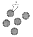
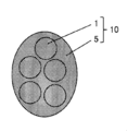
- FIG. 3 is a schematic cross-sectional view of an aggregate in which lithium phosphorus composite oxide particles are aggregated via a conductive carbon material.
- 2 is an electron micrograph of an aggregate (A2) obtained in Example 1.
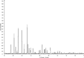
- 2 is an X-ray diffraction chart of an aggregate (A2) obtained in Example 1.
- FIG. 4 is an electron micrograph of a stirred product (c2) obtained in Comparative Example 3.
- the lithium phosphorus composite oxide carbon composite of the present invention has the following general formula (1): LiMPO 4 (1) (Wherein M represents one or more metal elements selected from the group consisting of Fe, Mn, Co, Ni, and V). Lithium phosphorus composite oxide particles represented by aggregation are aggregated via a conductive carbon material. A lithium phosphorus composite oxide-carbon composite having an average particle diameter of 1 to 30 ⁇ m and a tap density of the aggregate of 0.8 g / cm 3 or more.
- the lithium phosphorus composite oxide-carbon composite of the present invention first comprises a raw material mixture (a) obtained by mixing a lithium source, a phosphorus source, an M metal element source, and a conductive carbon material source.
- the obtained composite (a) 3 is mechanochemically treated to agglomerate the plurality of composites (a) 3 while compressing them.
- FIG. 1 is a schematic cross-sectional view of the composite (a) 3 obtained by firing the raw material mixture (a), and FIG. 2 shows that the composite (a) is mechanochemically treated.
- 1 is a schematic cross-sectional view of an aggregate (a) 10 obtained by the above, that is, a lithium phosphorus composite oxide carbon composite of the present invention.
- the lithium phosphorus composite oxide particles 1 of the composite (a) 3 are fine particles because they are obtained by firing the raw material mixture (a) at a low temperature of 500 to 900 ° C.
- the composite (a) 3 is a lithium phosphorus composite oxide carbon composite in which the surface of the fine lithium phosphorus composite oxide particles 1 is covered with the conductive carbon material (a1) 2.
- the conductive carbon material (a 1) 2 is an aggregate of powdered conductive carbon materials having a particle diameter smaller than that of the lithium phosphorus composite oxide particles 1, or the conductive carbon material is integrally formed. It is a coated film.
- the conductive carbon material (a1) 2 is formed by laminating a large number of powdered conductive carbon materials on the surface of the lithium phosphorus composite oxide particles 1 or the lithium phosphorus composite oxide particles 1. It is a film-like conductive carbon material covering the surface.
- the aggregate (a) 10 is subjected to mechanochemical treatment of the composite (a) 3 so that mechanical energy such as compressive force and shear force is applied to the plurality of composites (a) 3.
- the plurality of composite bodies (a) 3 are aggregates aggregated while being compressed.
- the conductive carbon material (a1) is strongly compressed by the mechanochemical treatment, it becomes a dense conductive carbon material (a2) 5.
- the aggregate (a) 10 includes a plurality of fine lithium-phosphorus composite oxide particles 1 through a compact of the conductive carbon material (a1) 2, that is, a dense conductive carbon material (a2) 5. It is an aggregate that is strongly aggregated.
- the conductive carbon material does not exist only on the surface as in the composite (a) 2, but the conductive carbon material also exists in the aggregate.
- the raw material mixture (a) is fired to obtain the composite (a) 3
- the raw material mixture (a) is pressure-molded in order to increase the reactivity between the raw materials, so that the conductive carbon material (a1 ) 2 is compressed with a force that is pressurized during pressure molding. Therefore, the density of the conductive carbon material (a1) 2 is higher than the density of the conductive carbon material source as a raw material.
- the force applied during the pressure molding is smaller than the force applied by the mechanochemical treatment in the subsequent process. Therefore, the density of the conductive carbon material (a1) 2 coated on the surface of the composite (a) 3 is smaller than the density of the conductive carbon material (a2) 5 in the aggregate (a) 10.
- the lithium phosphorus composite oxide particles represented by the general formula (1) relating to the lithium phosphorus composite oxide carbon composite of the present invention are fine lithium phosphorus composite oxide particles present in the aggregate.
- M represents one or more metal elements selected from the group consisting of Fe, Mn, Co, Ni and V.
- M may be a single type or a combination of two or more types.
- Fe is the operating voltage of a lithium secondary battery using a lithium phosphorus composite oxide carbon composite as a positive electrode active material, and the operating voltage of a lithium secondary battery using a lithium cobaltate composite oxide as a positive electrode active material. This is preferable in that an appropriate voltage can be maintained.
- the conductive carbon material examples include natural graphite such as scaly graphite, scaly graphite and earthy graphite, and graphite such as artificial graphite; carbon black, acetylene black, ketjen black, channel black, and furnace black. Carbon blacks such as lamp black and thermal black; carbon fibers and the like. Among these, ketjen black is preferable.
- the conductive carbon material may be one of these alone or a combination of two or more.
- the precursor of the conductive carbon material is fired at 500 to 900 ° C., preferably 550 to 700 ° C. in an inert gas atmosphere. It may be obtained by this.
- the precursor of the conductive carbon material is fired at 500 to 900 ° C., preferably 550 to 700 ° C. in an inert gas atmosphere, so that the conductive carbon according to the lithium phosphorus composite oxide carbon composite of the present invention is obtained. Any material that can be converted into a material may be used.
- Examples of the precursor of the conductive carbon material include, for example, coal tar pitch from soft pitch to hard pitch; coal heavy oil such as dry distillation liquefied oil, normal pressure residual oil, DC heavy oil of reduced pressure residual oil, crude oil, Petroleum heavy oil of cracked heavy oil such as ethylene tar by-produced during thermal decomposition of naphtha, etc .; Aromatic hydrocarbons such as acenaphthylene, decacyclene, anthracene, phenanthrene; Polyphenylene such as phenazine, biphenyl, terphenyl; Vinyl chloride; water-soluble polymers such as polyvinyl alcohol, polyvinyl butyral, and polyethylene glycol, and insolubilized products thereof; nitrogen-containing polyacrylonitrile; organic polymers such as polypyrrole; organic polymers such as sulfur-containing polythiophene and polystyrene Starch, cellulose, lignin, mannan, polygalacturonic acid, Natural polymers such as sacchar
- the precursor of the conductive carbon material may be one of these alone or a combination of two or more.
- the conductive carbon material precursor is fired in an inert gas atmosphere to form a large number of fine granular conductive carbon materials that are layered on the surface of the lithium phosphorus composite oxide particles. There are some that become a film-like conductive carbon material that covers the surface of the lithium phosphorus complex oxide particles.
- the average particle diameter of the aggregate according to the lithium phosphorus complex oxide-carbon composite of the present invention is an average particle diameter determined by a laser light scattering method, and is 1 to 30 ⁇ m, preferably 1 to 20 ⁇ m.
- the average particle size of the aggregate is less than the above range, the rate characteristics of the lithium secondary battery are low, and when it exceeds the above range, the rate characteristics are low.
- the tap density of the aggregate according to the lithium phosphorus composite oxide carbon composite of the present invention is 0.8 g / cm 3 or more, preferably 0.8 to 2.0 g / cm 3 , particularly preferably 0.9 to 2. 0.0 g / cm 3 .
- the conductive carbon material (conductive carbon material (a2) indicated by reference numeral 5 in FIG. 2) in the lithium phosphorus composite oxide carbon composite of the present invention is a conductive carbon material (conductive conductivity indicated by reference numeral 2 in FIG. 1). Since the carbon material (a1)) is compressed, it is a dense conductive carbon material. In the present invention, the fact that the tap density of the aggregate is within the above range means that the conductive carbon material is a compressed dense conductive carbon material.
- the density of the conductive carbon material (a) 2 covering the composite (a) 3 in FIG. 1, for example, the composite (a) 3 in FIG. ) is smaller than the above range. And when the tap density of an aggregate exists in the said range, the electrode density of a positive electrode active material becomes high, and the rate characteristic of a lithium secondary battery becomes high.
- the average particle diameter of the lithium phosphorus composite oxide particles represented by the general formula (1) present in the aggregate is an average particle diameter determined by a scanning electron microscope (SEM), preferably 10 to 500 nm, particularly preferably 10 to 300 nm.
- SEM scanning electron microscope
- the average particle diameter of the lithium phosphorus complex oxide particles represented by the general formula (1) present in the aggregate is obtained as follows. First, the aggregate is observed with a scanning electron micrograph (SEM), and the obtained SEM photograph is used to measure the particle size of each lithium phosphorus composite oxide particle present inside the aggregate. Further, for 20 arbitrarily selected aggregates, the particle diameter of each lithium phosphorus complex oxide existing inside the aggregate is similarly measured. Next, the average particle diameter is calculated by averaging all the particle diameters.
- SEM scanning electron micrograph
- the content of the conductive carbon material in the aggregate is preferably 0.5 to 10% by mass, particularly preferably 1 to 10% by mass in terms of carbon atoms. It is.
- the content of the conductive carbon material in the aggregate is within the above range, the battery capacity of the lithium secondary battery is high and the capacity reduction is also reduced.
- the content of the conductive carbon material in the aggregate is less than the above range, the battery capacity of the lithium secondary battery tends to be low, and if the content exceeds the above range, the capacity of the lithium secondary battery is greatly reduced. Easy to be.
- the content of the conductive carbon material is determined by measuring with a TOC total organic carbon meter (such as TOC-5000A manufactured by Shimadzu Corporation).
- the electrode density of the aggregate is preferably 2.8 g / cm 3 or more, particularly preferably 2.9-3. 3 g / cm 3 .
- the BET specific surface area of the aggregate is preferably 10 m 2 / g or more, particularly preferably 10 to 100 m 2 / g, from the viewpoint of improving the electrode coatability. .
- the lithium phosphorus composite oxide-carbon composite of the present invention is suitably manufactured by the following method for manufacturing a lithium phosphorus composite oxide-carbon composite of the present invention.
- the method for producing the lithium phosphorus composite oxide-carbon composite of the first aspect of the present invention (hereinafter also referred to as the method (1) for producing the lithium phosphorus composite oxide-carbon composite of the present invention) is a lithium source.
- a raw material mixture (a) containing a phosphorus source, one or more metal element (M metal element) sources selected from the group consisting of Fe, Mn, Co, Ni and V, and a conductive carbon material source A raw material mixing step (a) to obtain, a pressure molding step (a) to obtain a pressure molded body of the raw material mixture (a) by pressure molding the raw material mixture (a), and the raw material mixture (a)
- the pressure-molded body was fired at 500 to 900 ° C.
- LiMPO 4 (1) (Wherein, M represents one or more metal elements selected from the group consisting of Fe, Mn, Co, Ni, and V).
- M represents one or more metal elements selected from the group consisting of Fe, Mn, Co, Ni, and V).
- the lithium phosphorus composite oxide particles represented by the above are coated with a conductive carbon material.
- the raw material mixing step (a) according to the production method (1) of the lithium phosphorus composite oxide carbon composite of the present invention comprises a lithium source, a phosphorus source, an M metal element source, and a conductive carbon material source. This is a step of obtaining the raw material mixture (a) to be contained.
- the lithium source according to the raw material mixing step (a) may be a compound having a lithium element that generates a lithium-phosphorus composite oxide represented by the general formula (1) by reacting with another raw material.
- Examples thereof include inorganic lithium salts such as lithium hydroxide and lithium carbonate, and organic lithium salts such as lithium oxalate and lithium acetate.
- the phosphorus source in the raw material mixing step (a) may be a compound having a phosphorus element that generates a lithium-phosphorus composite oxide represented by the general formula (1) by reacting with another raw material.
- M metal element sources selected from the group consisting of Fe, Mn, Co, Ni and V in the raw material mixing step (a), by reacting with other raw materials, the above general formula If it is a compound which has M metal element which produces
- examples of the M metal element source include iron oxalate, iron acetate, iron oxide, iron hydroxide, iron carbonate, iron sulfate, and iron nitrate.
- the combination of a compound serving both as a lithium source and a phosphorus source and a compound serving as both a phosphorus source and an M metal element source facilitates the reaction operation. This is preferable in that the process can be simplified.
- Examples of such a compound serving both as a lithium source and a phosphorus source include lithium phosphate, and an example of such a compound serving as both a phosphorus source and an M metal element source is a phosphate having an M metal element. It is done.
- the average particle size of the lithium source, the phosphorus source and the M metal element source in the raw material mixing step (a) is preferably 100 ⁇ m or less, particularly preferably 0.1 to 100 ⁇ m in that a uniform mixture can be obtained. Moreover, it is preferable that the lithium source, the phosphorus source, and the M metal element source according to the raw material mixing step (a) have as high a purity as possible in order to obtain a high-purity lithium phosphorus composite oxide-carbon composite.
- the conductive carbon material source according to the raw material mixing step (a) is a conductive carbon material or a precursor of a conductive carbon material.
- the conductive carbon material related to the conductive carbon material source in the raw material mixing step (a) is the same as the conductive carbon material related to the lithium phosphorus complex oxide carbon composite of the present invention.
- the precursor of the conductive carbon material which concerns on the conductive carbon material source of a raw material mixing process (a) is the same as the precursor of the conductive carbon material which concerns on the lithium phosphorus complex oxide carbon composite of this invention. .
- the conductive carbon material source according to the raw material mixing step (a) is one or more conductive carbon materials, a precursor of one or more conductive carbon materials, one or more conductive materials.
- a combination of a conductive carbon material and a precursor of one or more conductive carbon materials may be used.
- the conductive carbon material source is preferably a combination of one or two or more kinds of conductive carbon materials and one or more kinds of precursors of the conductive carbon materials in terms of high rate characteristics. A combination of chain black and saccharide is particularly preferred.
- the average particle diameter of the conductive carbon material according to the conductive carbon material source in the raw material mixing step (a) is preferably 1.0 to 50.0 ⁇ m, particularly preferably 1.0 to 10.0 ⁇ m.
- the electrode density when the lithium phosphorus composite oxide carbon composite is used as the positive electrode active material is increased.
- the BET specific surface area of the conductive carbon material according to the conductive carbon material source in the raw material mixing step (a) is preferably 100 m 2 / g or more, particularly preferably 100 to 1500 m 2 / g, in that a uniform mixture can be obtained. It is.
- the mixing ratio of the lithium source and the phosphorus source is preferably such that the molar ratio of Li atom / P atom is 0.8 to 1.2 in terms of increasing the discharge capacity. Particularly preferred is .9 to 1.1.
- the mixing ratio of the phosphorus source and the M metal element source is preferably such that the molar ratio of Li atom / P atom is 0.8 to 1.2 in terms of increasing the discharge capacity. Particularly preferred is 0.9 to 1.1.
- the amount of the conductive carbon material source mixed is the amount obtained by performing the granulation step (a) in that the positive electrode active material is prevented from being oxidized and the capacity of the lithium secondary battery is increased.
- the amount of carbon atoms in the aggregate (a) is preferably 0.5 to 10% by mass, particularly preferably 1 to 10% by mass.
- an aggregate obtained by performing the granulation step (a) in consideration of the firing temperature and the like is adjusted so that the carbon atom content in a) falls within the above range.
- the method for obtaining the raw material mixture (a) is not particularly limited, and for example, without using a solvent, a lithium source, a phosphorus source, an M metal element source, and a conductive carbon material.
- examples include dry mixing to mix a source, wet mixing in which a lithium source, a phosphorus source, an M metal element source, and a conductive carbon material source are dissolved or dispersed in a solvent and mixed using a solvent.
- dry mixing is preferable in this case.
- the lithium source, the phosphorus source, and the M metal element source may be mixed first, and then the conductive carbon material source may be mixed with them.
- the lithium source, the phosphorus source, the M metal element source, and the conductive carbon material source may be mixed at a time.
- a dry mixing method includes a lithium source, a phosphorus source, an M metal element source, and a conductive carbon material source.
- the method of mixing by the mechanical means which acts is mentioned.
- the mixing device used for dry mixing include a rolling ball mill, a vibration mill, a planetary mill, a medium stirring mill, and the like.
- the raw material mixture (a) is mixed with the pulverized medium such as balls and beads in a mixing container in the mixing apparatus, and the raw material is mixed with the shearing force and frictional force of the granular medium.
- the mixture (a) is mixed while being pulverized.
- the particle diameter of the granular medium according to the mixing device for performing dry mixing is preferably 0.1 to 25 mm.
- the material of the granular medium related to the mixing apparatus for performing dry mixing is ceramic beads such as zirconia and alumina because of high hardness and resistance to wear and prevention of metal contamination of the material.
- the filling amount (filling volume) of the granular medium in the mixing container in the mixing apparatus for performing dry mixing is appropriately 50 to 90% of the volume in the mixing container.
- a lithium source, a phosphorus source, and an M metal element source are added to a solution in which a conductive carbon material precursor is dissolved in a solvent, and these are mixed.
- the solvent for wet mixing water, tetrahydrofuran, ketones such as acetone, alcohols such as methanol and ethanol, amides such as dimethylformamide and dimethylacetamide, Examples thereof include hydrocarbons such as toluene, xylene and benzene, and these may be used alone or in combination of two or more.
- the solid content concentration of the lithium source, the phosphorus source and the M metal element source in the slurry obtained by mixing the lithium source, the phosphorus source and the M metal element source with the solution obtained by dissolving the precursor of the conductive carbon material in the solvent is The amount is preferably 10 to 50% by mass, particularly preferably 10 to 40% by mass.
- the mixing device used for wet mixing include a mixing device used for dry mixing.
- the particle size of the pulverizing medium relating to the mixing device for performing wet mixing is preferably 1 to 25 mm.
- the material of the pulverizing medium related to the mixing apparatus for performing the wet mixing is ceramic beads such as zirconia and alumina because of high hardness and resistance to wear and prevention of metal contamination of the material.
- the obtained slurry is heated at 50 to 150 ° C., preferably under reduced pressure at 50 to 150 ° C. By heating or spray drying, the solvent is removed from the slurry to obtain the raw material mixture (a).
- the raw material mixture (a) is pressure molded, and the raw material mixture (a) is pressure molded. It is a process of obtaining a body.
- the pressure applied during the pressure molding of the raw material mixture (a) varies depending on the type of press and the amount of the raw material mixture (a), but is usually 5 to 200 MPa, preferably 20 to 200 MPa.
- the press machine used for pressure molding include a hand press machine, a tableting machine, a briquette machine, and a roller compactor.
- the raw material mixture (a) is pressurized and molded to increase the reactivity of the raw material in the subsequent firing step (a).
- the pressure-molded body of the raw material mixture (a) is placed in an inert gas atmosphere such as nitrogen or argon.
- the firing temperature when firing the pressure-molded body of the raw material mixture (a) is within the above range, so that it is represented by the general formula (1) in the aggregate (a).
- the lithium phosphorus composite oxide particles are made finer, preferably the average particle diameter of the lithium phosphorus composite oxide particles represented by the general formula (1) is 10 to 500 nm, particularly preferably the general formula (1)
- the average particle size of the lithium phosphorus composite oxide particles represented by 1) can be 10 to 300 nm.
- the firing time when firing the pressure-molded body of the raw material mixture (a) is preferably 2 to 20 hours, particularly preferably 5 to 10 hours.
- the fired product after firing the pressure-molded body of the raw material mixture (a) may be pulverized, and the pulverized product may be fired again.
- the fired product is cooled.
- Such cooling can be performed in an inert gas atmosphere such as nitrogen or argon. preferable.
- the fired product obtained by performing the firing step (a) is a composite in which lithium phosphorus composite oxide particles represented by the general formula (1) are coated with a conductive carbon material as shown in FIG. a).
- the composite (a) may be pulverized before the granulation step (a), and the granulation step (a) is performed. Before performing, it is preferable that the composite (a) is pulverized in that an aggregate (a) having a high tap density is obtained.
- the granulation step (a) according to the production method (1) of the lithium phosphorus composite oxide carbon composite of the present invention has an average particle diameter of 1 to 30 ⁇ m and a tap density of 0.8 g / cm 3 or more.
- the composite (a) is mechanochemically processed to obtain an aggregate (a) in which the lithium phosphorus composite oxide particles represented by the general formula (1) are aggregated via a conductive carbon material. It is a process.
- the mechanochemical treatment relating to the granulation step (a) is a treatment for applying mechanical energy such as compressive force, shear force, friction force, stretching force, etc. to the composite (a). Then, since mechanical energy is applied to the composite (a), the multiple composites (a) are aggregated while being compressed, so that the lithium phosphorus composite oxide particles represented by the general formula (1) are densely packed. An aggregate (a) aggregated via a conductive carbon material is obtained.
- Mechanisms for performing mechanochemical treatment for example, “Mechano-Fusion System (manufactured by Hosokawa Micron)”, “Nobilta (manufactured by Hosokawa Micron)”, etc., simultaneously applies a compressive force and a shearing force to the object to be treated. Compressive force shearing dry equipment capable of In addition, as an apparatus for performing mechanochemical treatment, for example, “hybridization system (manufactured by Nara Machinery Co., Ltd.)” can be mentioned.
- the following conditions may be mentioned as processing conditions when performing mechanochemical processing with such a compressive force shearing type dry apparatus.
- the peripheral speed of the rotor is 30 to 100 m / s, preferably 30 to 80 m / s.
- the treatment temperature is 100 ° C. or lower, preferably ⁇ 10 to 80 ° C.
- the treatment atmosphere is preferably an inert atmosphere.
- a processing device and processing conditions for mechanochemical processing are appropriately selected, and for example, by adjusting the type of the device, the peripheral speed of the rotor, processing time, and the like (
- the mechanochemical treatment of the composite (a) is performed until the average particle diameter of a) becomes 1 to 30 ⁇ m and the tap density becomes 0.8 g / cm 3 or more.
- the average particle size of the aggregate (a) is 1 to 30 ⁇ m, preferably 1 to 20 ⁇ m.
- the rate characteristics of the lithium secondary battery are lowered, and when it exceeds the above range, the rate characteristics are lowered.
- the tap density of the aggregate (a) is 0.8 g / cm 3 or more, preferably 0.8 to 2.0 g / cm 3 , particularly preferably 0.9 to 2.0 g / cm 3 .
- the electrode density of the positive electrode active material is increased, and the rate characteristics of the lithium secondary battery are increased.
- the aggregate (a) can be obtained by performing the granulation step (a).
- the obtained aggregate (a) is pulverized and classified after the granulation step (a).
- the method for producing a lithium phosphorus composite oxide-carbon composite of the second aspect of the present invention (hereinafter also referred to as the method (2) for producing a lithium phosphorus composite oxide-carbon composite of the present invention) is a lithium source.
- a phosphorus source one or more metal element (M metal element) sources selected from the group consisting of Fe, Mn, Co, Ni, and V, and a precursor of a conductive carbon material, and a first raw material mixture
- LiMPO 4 (1) LiMPO 4 (1)
- M represents one or more metal elements selected from the group consisting of Fe, Mn, Co, Ni, and V.
- the lithium phosphorus composite oxide particles represented by the above are coated with a conductive carbon material.
- the first raw material mixing step (b) according to the production method (2) of the lithium phosphorus composite oxide carbon composite of the present invention includes a lithium source, a phosphorus source, and a group of Fe, Mn, Co, Ni, and V. It is a step of obtaining a first raw material mixture (b1) by mixing at least one selected metal element source (M metal element source) and a precursor of a conductive carbon material.
- M metal element source selected metal element source
- the lithium source, the phosphorus source, the M metal element source and the conductive carbon material precursor according to the first raw material mixing step (b) are the lithium source, the phosphorus source, the M metal element source and the conductive material according to the raw material mixing step (a). The same as the precursor of the carbonaceous material.
- the method is the same as the method of obtaining the raw material mixture (a) by mixing the lithium source, the phosphorus source, the M metal element source, and the conductive carbon material source.
- the second raw material mixture (b1) is mixed with a conductive carbon material, In this step, the raw material mixture (b2) is obtained.
- the conductive carbon material according to the second raw material mixing step (b) is the same as the conductive carbon material according to the raw material mixing step (a).
- the method of obtaining the second raw material mixture (b2) by mixing the first raw material mixture (b1) and the conductive carbon material includes a lithium source, a phosphorus source, and an M metal.
- the lithium source, the phosphorus source, the M metal element source, and the conductive carbon material source are mixed in the raw material mixing step (a) except that the first raw material mixture (b1) is used instead of the element source. And it is the same as that of the method of obtaining a raw material mixture (a).
- the second raw material mixture (b2) is pressure molded to produce the second raw material mixture (b2). It is the process of obtaining the press-molded body.
- the second raw material mixture (b2) is pressure molded to obtain a pressure molded body of the second raw material mixture (b2).
- the raw material mixture (a) is pressure-molded to obtain a pressure-molded body of the raw material mixture (a).
- the pressure-molded body of the second raw material mixture (b2) is subjected to an inert gas atmosphere such as nitrogen or argon.
- the method of obtaining the composite (b) by firing the pressure-molded body of the second raw material mixture (b2) is different in the firing step (a) except that the object to be fired is different. This is the same as the method for obtaining the composite (a) by firing the pressure-molded body of the raw material mixture (a).
- the granulation step (b) according to the production method (2) of the lithium phosphorus composite oxide carbon composite of the present invention has an average particle diameter of 1 to 30 ⁇ m and a tap density of 0.8 g / cm 3 or more.
- the composite (b) is mechanochemically processed to obtain an aggregate (b) in which the lithium phosphorus composite oxide particles represented by the general formula (1) are aggregated via a conductive carbon material. It is a process.
- the method of obtaining the aggregate (b) by mechanochemical treatment of the composite (b) is the same as that in the granulation step (a) except that the object to be mechanochemically treated is different. This is the same as the method of obtaining the aggregate (a) by subjecting the body (a) to mechanochemical treatment.
- Mass of mixed amount (x1) of precursor of conductive carbon material mixed in first raw material mixing step (b) and mixed amount (x2) of conductive carbon material mixed in second raw material mixing step (b) When the ratio is within the above range, the rate characteristics of the lithium secondary battery are enhanced.
- the aggregate (b) can be obtained by performing the granulation step (b).
- the obtained aggregate (b) is pulverized and classified.
- the method for producing a lithium phosphorus composite oxide-carbon composite of the third aspect of the present invention is a lithium source.
- a phosphorus source one or more metal element (M metal element) sources selected from the group consisting of Fe, Mn, Co, Ni and V, and a conductive carbon material precursor, and a raw material mixture ( c) a raw material mixing step (c), a pressure forming step (c) for pressure-molding the raw material mixture (c) to obtain a pressure-molded body of the raw material mixture (c), and the raw material mixture
- M metal element metal element
- LiMPO 4 (1) (Wherein, M represents one or more metal elements selected from the group consisting of Fe, Mn, Co, Ni, and V).
- the lithium phosphorus composite oxide particles represented by the above are coated with a conductive carbon material.
- the mixture of the composite (c) and the conductive carbon material is subjected to mechanochemical treatment until the amount becomes 8 g / cm 3 or more, and the lithium phosphorus composite oxide particles represented by the general formula (1) are conductive.
- the raw material mixing step (c) according to the production method (3) of the lithium phosphorus composite oxide-carbon composite of the present invention is selected from the group consisting of a lithium source, a phosphorus source, Fe, Mn, Co, Ni and V.
- a metal element (M metal element) sources and a conductive carbon material precursor are mixed to obtain a raw material mixture (c).
- the lithium source, phosphorus source, M metal element source, and conductive carbon material precursor according to the raw material mixing step (c) are the lithium source, phosphorus source, M metal element source, and conductive carbon according to the raw material mixing step (a). The same as the precursor of the material.
- the method of obtaining the raw material mixture (c) by mixing the lithium source, the phosphorus source, the M metal element source, and the precursor of the conductive carbon material is the raw material mixing step (a ),
- the raw material mixture (c) is pressure molded, and the raw material mixture (c) is pressure molded. It is a process of obtaining a body.
- the raw material mixture (c) is subjected to pressure molding to obtain a pressure molded body of the raw material mixture (c).
- the raw material mixture (a) Is the same as the method of obtaining a pressure-molded body of the raw material mixture (a).
- the pressure-molded body of the raw material mixture (c) is placed in an inert gas atmosphere such as nitrogen or argon.
- the method of obtaining the composite (c) by firing the pressure-molded body of the raw material mixture (c) is the same as that of the raw material mixture (a) in the firing step (a). This is the same as the method for firing to obtain the composite (a).
- a conductive carbon material is further added to the composite (c), and then the average of aggregates
- the mixture of the composite (c) and the conductive carbon material is mechanochemically processed until the particle diameter is 1 to 30 ⁇ m and the tap density is 0.8 g / cm 3 or more, and the mixture is represented by the general formula (1).
- This is a step of obtaining an aggregate (c) in which lithium phosphorus composite oxide particles are aggregated via a conductive carbon material.
- a conductive carbon material is added to the composite (c).
- the conductive carbon material according to the granulation step (c) is the same as the conductive carbon material according to the raw material mixing step (a).
- a method of adding the conductive carbon material to the composite (c) it is usually performed by adding the composite (c) and the conductive carbon material to an apparatus for performing a mechanochemical treatment. You may mix both beforehand, before adding to the apparatus for processing.
- a mechanochemical treatment is then performed on the mixture of the composite (c) and the conductive carbon particles.
- the method is the same as the method of obtaining the aggregate (a) by mechanochemical treatment of the composite (a).
- the mass ratio of the mixed amount (x1) of the precursor of the conductive carbon material mixed in the raw material mixing step (c) and the mixed amount (x2) of the conductive carbon material mixed in the granulation step (c) is in the above range. By being inside, the rate characteristic of a lithium secondary battery becomes high.
- the aggregate (c) can be obtained by performing the granulation step (c).
- the obtained aggregate (c) is pulverized and classified.
- the processing step, the processing conditions, etc. are appropriately selected so that the mixing target is mixed, and the mixing step is performed. Can be implemented.
- granulation step granulation is performed by performing mechanochemical treatment on the object of mechanochemical treatment to form an aggregate. As described above, the granulating step can be performed by appropriately selecting a processing apparatus, processing conditions, and the like.
- the lithium phosphorus composite oxide carbon composite of the present invention is formed by compressing and agglomerating fine lithium phosphorus composite oxide particles and a conductive carbon material, a plurality of fine composites present in the aggregate. Lithium phosphorus complex oxide particles are aggregated via a dense conductive carbon material.
- the conductive carbon material in the lithium phosphorus composite oxide carbon composite of the present invention has a higher density than the conductive carbon material of the conventional lithium phosphorus composite oxide carbon composite. Therefore, the lithium phosphorus composite oxide-carbon composite of the present invention has a higher tap density than the conventional lithium phosphorus composite oxide-carbon composite, so that the electrode density is increased.
- the conductive carbon material in the lithium phosphorus composite oxide carbon composite of the present invention is denser than the conventional conductive carbon material of the lithium phosphorus composite oxide carbon composite, and therefore has high conductivity. Therefore, the lithium phosphorus composite oxide-carbon composite of the present invention has higher lithium secondary battery rate characteristics than the conventional lithium phosphorus composite oxide-carbon composite.
- the lithium phosphorus composite oxide particles in the lithium phosphorus composite oxide carbon composite of the present invention are covered with a dense conductive carbon material, the lithium phosphorus composite oxide carbon composite of the present invention.
- the lithium secondary battery has higher rate characteristics than the conventional lithium phosphorus composite oxide-carbon composite.
- the positive electrode active material for a lithium secondary battery of the present invention is a positive electrode active material characterized by containing the lithium phosphorus complex oxide carbon composite of the present invention.
- the lithium secondary battery of the present invention is a lithium secondary battery that uses the lithium phosphorus complex oxide-carbon composite of the present invention as a positive electrode active material for a lithium secondary battery, and includes a positive electrode, a negative electrode, a separator, and a lithium salt. It consists of a nonaqueous electrolyte.
- the lithium phosphorus composite oxide carbon composite of the present invention When used as a positive electrode active material for lithium secondary batteries, the inclusion of the lithium phosphorus composite oxide carbon composite of the present invention in the positive active material for all lithium secondary batteries
- the amount is preferably 1 or more, and particularly preferably 3 or more, in terms of number in a 30 ⁇ m ⁇ 30 ⁇ m field of view by observation at a magnification of 3000 in scanning electron microscope observation (SEM).
- the positive electrode according to the lithium secondary battery of the present invention is formed, for example, by applying and drying a positive electrode mixture on a positive electrode current collector.
- the positive electrode mixture includes a positive electrode active material, a conductive agent, a binder, and a filler that is added as necessary.
- the positive electrode active material for a lithium secondary battery of the present invention is uniformly applied to the positive electrode. For this reason, the lithium secondary battery of the present invention has high battery performance, in particular, high load characteristics and cycle characteristics.
- the content of the positive electrode active material contained in the positive electrode mixture of the lithium secondary battery of the present invention is 70 to 100% by weight, preferably 90 to 98% by weight.
- the positive electrode current collector according to the lithium secondary battery of the present invention is not particularly limited as long as it is an electronic conductor that does not cause a chemical change in the constituted battery.
- the surface of these materials may be oxidized and used, or the current collector surface may be provided with irregularities by surface treatment.
- Examples of the current collector include foils, films, sheets, nets, punched ones, lath bodies, porous bodies, foam bodies, fiber groups, nonwoven fabric molded bodies, and the like.
- the thickness of the current collector is not particularly limited, but is preferably 1 to 500 ⁇ m.
- the conductive agent according to the lithium secondary battery of the present invention is not particularly limited as long as it is an electron conductive material that does not cause a chemical change in the constructed battery.
- graphite such as natural graphite and artificial graphite, carbon black, acetylene black, ketjen black, channel black, furnace black, lamp black, carbon black such as thermal black, conductive fibers such as carbon fiber and metal fiber
- Examples include metal powders such as carbon fluoride, aluminum and nickel powder, conductive whiskers such as zinc oxide and potassium titanate, conductive metal oxides such as titanium oxide, and conductive materials such as polyphenylene derivatives.
- graphite include scaly graphite, scaly graphite, and earthy graphite. These can be used alone or in combination of two or more.
- the blending ratio of the conductive agent is 1 to 50% by weight, preferably 2 to 30% by weight in the positive electrode mixture.
- binder according to the lithium secondary battery of the present invention examples include starch, polyvinylidene fluoride, polyvinyl alcohol, carboxymethylcellulose, hydroxypropylcellulose, regenerated cellulose, diacetylcellulose, polyvinylpyrrolidone, tetrafluoroethylene, polyethylene, and polypropylene.
- Ethylene-propylene-diene terpolymer EPDM
- sulfonated EPDM styrene butadiene rubber
- fluoro rubber tetrafluoroethylene-hexafluoroethylene copolymer
- tetrafluoroethylene-hexafluoropropylene copolymer tetrafluoroethylene-par Fluoroalkyl vinyl ether copolymer
- vinylidene fluoride-hexafluoropropylene copolymer vinylidene fluoride-chlorotrifluoroethylene Copolymer
- ethylene-tetrafluoroethylene copolymer polychlorotrifluoroethylene
- vinylidene fluoride-pentafluoropropylene copolymer propylene-tetrafluoroethylene copolymer
- ethylene-chlorotrifluoroethylene copolymer fluorine Vinylidene fluoride-hexafluoro
- the compound containing a functional group which reacts with lithium like a polysaccharide it is preferable to add the compound like an isocyanate group and to deactivate the functional group, for example.
- the blending ratio of the binder is 1 to 50% by weight, preferably 5 to 15% by weight in the positive electrode mixture.
- the filler according to the lithium secondary battery of the present invention suppresses the volume expansion of the positive electrode in the positive electrode mixture, and is added as necessary.
- any fibrous material can be used as long as it does not cause a chemical change in the constructed battery.
- olefinic polymers such as polypropylene and polyethylene, and fibers such as glass and carbon are used.
- the addition amount of the filler is not particularly limited, but is preferably 0 to 30% by weight in the positive electrode mixture.
- the negative electrode according to the lithium secondary battery of the present invention is formed by applying and drying a negative electrode material on a negative electrode current collector.
- the negative electrode current collector according to the lithium secondary battery of the present invention is not particularly limited as long as it is an electronic conductor that does not cause a chemical change in the constructed battery.
- the surface of these materials may be used after being oxidized, or the surface of the current collector may be used with surface roughness by surface treatment.
- Examples of the current collector include foils, films, sheets, nets, punched ones, lath bodies, porous bodies, foam bodies, fiber groups, nonwoven fabric molded bodies, and the like.
- the thickness of the current collector is not particularly limited, but is preferably 1 to 500 ⁇ m.
- the negative electrode material according to the lithium secondary battery of the present invention is not particularly limited, and examples thereof include carbonaceous materials, metal composite oxides, lithium metals, lithium alloys, silicon alloys, tin alloys, metal oxides. Materials, conductive polymers, chalcogen compounds, Li—Co—Ni-based materials, lithium titanate, and the like. Examples of the carbonaceous material include non-graphitizable carbon materials and graphite-based carbon materials.
- metal complex oxide for example, Sn p (M 1 ) 1-p (M 2 ) q Or (wherein M 1 represents one or more elements selected from Mn, Fe, Pb and Ge, M 2 represents Al, B, P, Si, group 1 of the periodic table, group 2, one or more elements selected from group 3 and a halogen element, 0 ⁇ p ⁇ 1,1 ⁇ q ⁇ 3 1 ⁇ r ⁇ 8), Li t Fe 2 O 3 (0 ⁇ t ⁇ 1), Li t WO 2 (0 ⁇ t ⁇ 1), and the like.
- the metal oxide GeO, GeO 2, SnO, SnO 2, PbO, PbO 2, Pb 2 O 3, Pb 3 O 4, Sb 2 O 3, Sb 2 O 4, Sb 2 O 5, Bi 2 O 3 Bi 2 O 4 , Bi 2 O 5 and the like.
- the conductive polymer include polyacetylene and poly-p-phenylene.
- an insulating thin film having a large ion permeability and a predetermined mechanical strength is used.
- Sheets and non-woven fabrics made of olefin polymers such as polypropylene, glass fibers or polyethylene are used because of their organic solvent resistance and hydrophobicity.
- the pore diameter of the separator may be in a range generally useful for batteries, for example, 0.01 to 10 ⁇ m.
- the thickness of the separator may be in a range for a general battery, for example, 5 to 300 ⁇ m.
- the solid electrolyte such as a polymer is used as the electrolyte described later, the solid electrolyte may also serve as a separator.
- the non-aqueous electrolyte containing a lithium salt according to the lithium secondary battery of the present invention is composed of a non-aqueous electrolyte and a lithium salt.
- a non-aqueous electrolyte, an organic solid electrolyte, or an inorganic solid electrolyte is used as the non-aqueous electrolyte according to the lithium secondary battery of the present invention.
- Non-aqueous electrolytes include, for example, N-methyl-2-pyrrolidinone, propylene carbonate, ethylene carbonate, butylene carbonate, dimethyl carbonate, diethyl carbonate, ⁇ -butyrolactone, 1,2-dimethoxyethane, tetrahydroxyfuran, 2-methyl Tetrahydrofuran, dimethyl sulfoxide, 1,3-dioxolane, formamide, dimethylformamide, dioxolane, acetonitrile, nitromethane, methyl formate, methyl acetate, phosphate triester, trimethoxymethane, dioxolane derivatives, sulfolane, methylsulfolane, 3-methyl -2-oxazolidinone, 1,3-dimethyl-2-imidazolidinone, propylene carbonate derivative, tetrahydrofuran derivative, diethyl ether, 1,3- Ropansaruton, methyl propionate, and a solvent
- Examples of the organic solid electrolyte according to the lithium secondary battery of the present invention include polyethylene derivatives, polyethylene oxide derivatives or polymers containing the same, polypropylene oxide derivatives or polymers containing the same, phosphate ester polymers, polyphosphazenes, polyaziridines, and polyethylenes.
- Examples thereof include a polymer containing an ionic dissociation group such as sulfide, polyvinyl alcohol, polyvinylidene fluoride, and polyhexafluoropropylene, and a mixture of a polymer containing an ionic dissociation group and the non-aqueous electrolyte.
- Li nitride, halide, oxyacid salt, sulfide, and the like can be used as the inorganic solid electrolyte according to the lithium secondary battery of the present invention.
- the inorganic solid electrolyte is amorphous (glass), lithium phosphate (Li 3 PO 4 ), lithium oxide (Li 2 O), lithium sulfate (Li 2 SO 4 ), phosphorus oxide (P 2 O 5) ), Oxygen-containing compounds such as lithium borate (Li 3 BO 3 ), Li 3 PO 4-u N 2u / 3 (u is 0 ⁇ u ⁇ 4), Li 4 SiO 4-u N 2u / 3 (u is Nitrogen such as 0 ⁇ u ⁇ 4), Li 4 GeO 4-u N 2u / 3 (u is 0 ⁇ u ⁇ 4), Li 3 BO 3-u N 2u / 3 (u is 0 ⁇ u ⁇ 3)
- the compound to be contained can be contained in the inorganic solid electrolyte. By adding the compound containing oxygen or the compound containing nitrogen, the gap between the formed amorphous skeletons can be widened, the hindrance to movement of lithium ions can be reduced, and ion conductivity can
- lithium salt those dissolved in the non-aqueous electrolyte are used, for example, LiCl, LiBr, LiI, LiClO 4 , LiBF 4 , LiB 10 Cl 10 , LiPF 6 , LiCF 3. SO 3 , LiCF 3 CO 2 , LiAsF 6 , LiSbF 6 , LiB 10 Cl 10 , LiAlCl 4 , CH 3 SO 3 Li, CF 3 SO 3 Li, (CF 3 SO 2 ) 2 NLi, chloroborane lithium, lower aliphatic
- examples thereof include a salt obtained by mixing one or more of lithium carboxylate, lithium tetraphenylborate, imides and the like.
- the following compounds can be added to the non-aqueous electrolyte for the purpose of improving discharge, charge characteristics, and flame retardancy.
- pyridine triethyl phosphite, triethanolamine, cyclic ether, ethylenediamine, n-glyme, hexaphosphoric acid triamide, nitrobenzene derivative, sulfur, quinoneimine dye, N-substituted oxazolidinone and N, N-substituted imidazolidine, ethylene glycol dialkyl ether , Ammonium salt, polyethylene glycol, pyrrole, 2-methoxyethanol, aluminum trichloride, conductive polymer electrode active material monomer, triethylenephosphonamide, trialkylphosphine, morpholine, aryl compounds with carbonyl group, hexamethylphosphine
- Examples include hollic triamide and 4-alkylmorpholine, bicyclic tertiary amines, oils, phosphonium salts
- a halogen-containing solvent such as carbon tetrachloride or ethylene trifluoride can be included in the electrolyte.
- carbon dioxide gas can be included in the electrolytic solution in order to make it suitable for high-temperature storage.
- the lithium secondary battery of the present invention is a lithium secondary battery excellent in rate characteristics, and the shape of the battery may be any shape such as a button, a sheet, a cylinder, a corner, or a coin type.
- the use of the lithium secondary battery of the present invention is not particularly limited, for example, a notebook computer, a laptop computer, a pocket word processor, a mobile phone, a cordless cordless handset, a portable CD player, a radio, an LCD TV, a backup power source, an electric shaver, Examples include electronic devices such as memory cards and video movies, and consumer electronic devices such as automobiles, electric vehicles, game machines, and electric tools.
- Example 1 ⁇ Raw material mixing process> 10 kg of ferrous phosphate hydrate (Fe 3 (PO 4 ) 2 ⁇ 8H 2 O, average particle size 10.1 ⁇ m) and 2.4 kg of lithium phosphate (Li 3 PO 4 average particle size 5.5 ⁇ m) Then, a slurry having a solid content concentration of 40% by mass was prepared by dispersing in water. Next, the slurry was placed in a wet bead mill apparatus and subjected to a wet mixing process. The water in the slurry was then evaporated and dried to obtain a mixture.
- the processing conditions in the wet bead mill apparatus are as follows. -Fluid medium: Zirconia beads (average particle size 0.5 mm) ⁇ Filling volume: 85% by volume ⁇ Peripheral speed: 10.0 m / s
- ketjen black (average particle size 0.05 ⁇ m, BET specific surface area 754 m 2 / g, manufactured by Ketjenblack International Co., Ltd., trade name ECP) is added to the obtained mixture, and the mixture is sufficiently mixed with a Henschel mixer. Thus, a raw material mixture was obtained.
- Example 2 ⁇ Raw material mixing process> 10 kg of ferrous phosphate hydrate (Fe 3 (PO 4 ) 2 ⁇ 8H 2 O, average particle size 10.1 ⁇ m) and 2.4 kg of lithium phosphate (Li 3 PO 4 average particle size 5.5 ⁇ m) Then, a slurry having a solid content concentration of 40% by mass was prepared by dispersing in water. Next, the slurry was placed in a wet bead mill apparatus, and wet mixing was performed under the same conditions as in Example 1. The water in the slurry was then evaporated and dried to obtain a mixture.
- ferrous phosphate hydrate Fe 3 (PO 4 ) 2 ⁇ 8H 2 O, average particle size 10.1 ⁇ m
- lithium phosphate Li 3 PO 4 average particle size 5.5 ⁇ m
- sucrose was added to the obtained mixture and sufficiently mixed with a Henschel mixer to obtain a raw material mixture.
- Example 3 ⁇ Raw material mixing process> 10 kg of ferrous phosphate hydrate (Fe 3 (PO 4 ) 2 ⁇ 8H 2 O, average particle size 10.1 ⁇ m) and 2.4 kg of lithium phosphate (Li 3 PO 4 average particle size 5.5 ⁇ m) Then, a slurry having a solid content concentration of 40% by mass was prepared by dispersing in water. Next, the slurry was placed in a wet bead mill apparatus, and wet mixing was performed under the same conditions as in Example 1. The water in the slurry was then evaporated and dried to obtain a mixture.
- ferrous phosphate hydrate Fe 3 (PO 4 ) 2 ⁇ 8H 2 O, average particle size 10.1 ⁇ m
- lithium phosphate Li 3 PO 4 average particle size 5.5 ⁇ m
- Example 4 ⁇ Raw material mixing process> 10 kg of ferrous phosphate hydrate (Fe 3 (PO 4 ) 2 ⁇ 8H 2 O, average particle size 10.1 ⁇ m) and 2.4 kg of lithium phosphate (Li 3 PO 4 average particle size 5.5 ⁇ m) Then, a slurry having a solid content concentration of 40% by mass was prepared by dispersing in water, and then 1.3 kg of sucrose was added to the slurry. Next, the obtained slurry was put in a wet bead mill apparatus, and wet mixing was performed under the same conditions as in Example 1. Next, water in the slurry was evaporated and dried to obtain a first raw material mixture.
- ferrous phosphate hydrate Fe 3 (PO 4 ) 2 ⁇ 8H 2 O, average particle size 10.1 ⁇ m
- lithium phosphate Li 3 PO 4 average particle size 5.5 ⁇ m
- Example 2 650 g of ketjen black used in Example 1 was added to the obtained first raw material mixture, and sufficiently mixed with a Henschel mixer to obtain a second raw material mixture.
- the obtained press-molded body was fired at 600 ° C. for 5 hours in a nitrogen atmosphere, and after firing, it was cooled in a nitrogen atmosphere. Next, the obtained fired product was pulverized and then classified to obtain a composite (a1). XRD analysis of the obtained composite (a1) confirmed that single-phase LiFePO 4 was produced.
- sucrose was added to the obtained mixture and sufficiently mixed with a Henschel mixer to obtain a raw material mixture.
- the obtained press-molded body was fired at 600 ° C. for 5 hours in a nitrogen atmosphere, and after firing, it was cooled in a nitrogen atmosphere. Next, the obtained fired product was pulverized and then classified to obtain a composite (b1). When the obtained composite (b1) was subjected to XRD analysis, it was confirmed that single-phase LiFePO 4 was produced.
- the obtained press-molded body was fired at 600 ° C. for 5 hours in a nitrogen atmosphere, and after firing, it was cooled in a nitrogen atmosphere. Next, the obtained fired product was pulverized and then classified to obtain a composite (c1). When the obtained composite (c1) was analyzed by XRD, it was confirmed that single-phase LiFePO 4 was formed.
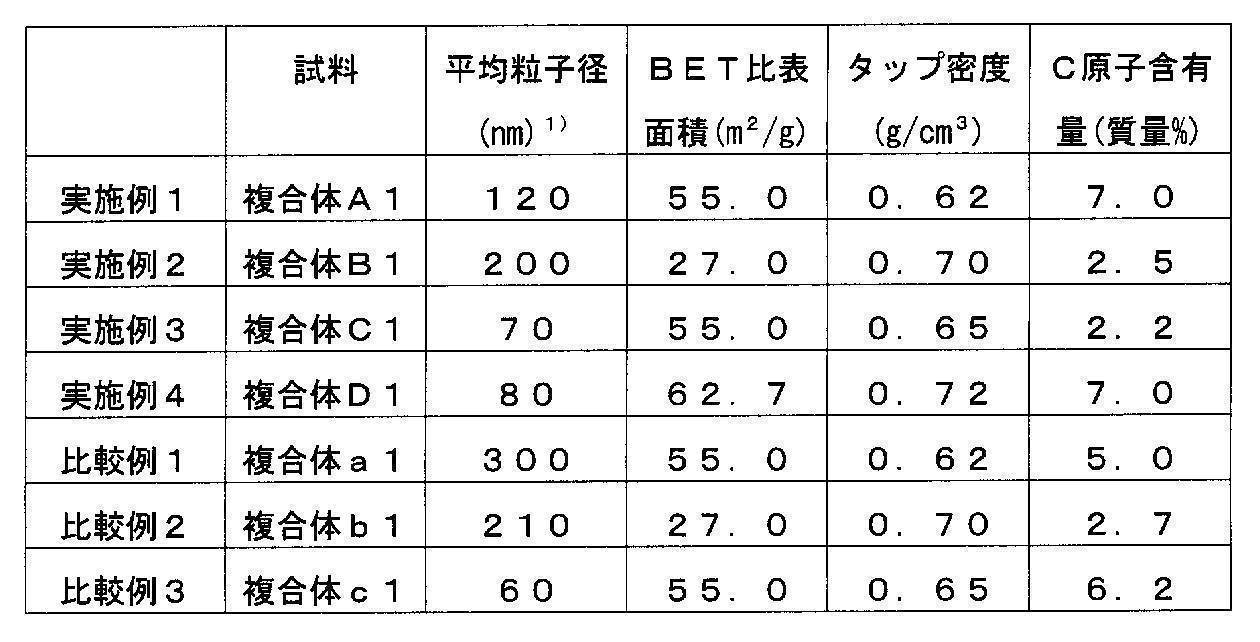
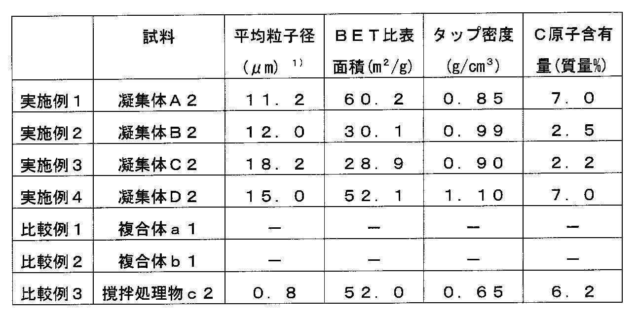
- Lithium phosphorus composite oxide in the composites (A1) to (D1) obtained in Examples 1 to 4 and composites (a1) to (c1) obtained in Comparative Examples 1 to 3 The average particle diameter of the particles, the BET specific surface area, the tap density, and the carbon atom content of the composites (A1) to (D1) and the composites (a1) to (c1) were determined.
- SEM scanning electron microscope
- FIG. 3 shows an electron micrograph of the aggregate A2 obtained in Example 1
- FIG. 4 shows an X-ray diffraction chart.
- the electron micrograph of the stirring processed material (c2) obtained in Comparative Example 3 is shown in FIG.
- Examples 1 to 4 are average particle diameters of aggregates, and Comparative Example 3 is an average particle diameter of lithium phosphorus composite oxide particles in the composite
- a lithium secondary battery was manufactured using each member such as a separator, a negative electrode, a positive electrode, a current collector plate, a mounting bracket, an external terminal, and an electrolytic solution.
- a metal lithium foil was used for the negative electrode, and 1 mol of LiPF 6 dissolved in 1 liter of a 1: 1 kneaded solution of ethylene carbonate and diethyl carbonate was used for the electrolyte.
- Electrode density evaluation method The thickness and weight of the positive electrode plate obtained by punching into a disk having a diameter of 15 mm in (I) were measured, and the electrode density was calculated.
Landscapes
- Chemical & Material Sciences (AREA)
- Inorganic Chemistry (AREA)
- Chemical Kinetics & Catalysis (AREA)
- Electrochemistry (AREA)
- General Chemical & Material Sciences (AREA)
- Organic Chemistry (AREA)
- Engineering & Computer Science (AREA)
- Materials Engineering (AREA)
- Crystallography & Structural Chemistry (AREA)
- Manufacturing & Machinery (AREA)
- Battery Electrode And Active Subsutance (AREA)
Abstract
Description
LiMPO4 (1)
(式中、MはFe、Mn、Co、Ni及びVの群から選ばれる1種以上の金属元素を示す。)で表わされるリチウムリン系複合酸化物粒子が導電性炭素材料を介して凝集している凝集体であり、該凝集体の平均粒子径が1~30μmであり、該凝集体のタップ密度が0.8g/cm3以上であることを特徴とするリチウムリン系複合酸化物炭素複合体を提供するものである。
LiMPO4 (1)
(式中、MはFe、Mn、Co、Ni及びVの群から選ばれる1種以上の金属元素を示す。)で表わされるリチウムリン系複合酸化物粒子が導電性炭素材料で被覆された複合体(a)を得る焼成工程(a)と、 凝集体の平均粒子径が1~30μm且つタップ密度が0.8g/cm3以上となるまで、該複合体(a)をメカノケミカル処理して、前記一般式(1)で表わされるリチウムリン系複合酸化物粒子が導電性炭素材料介して凝集している凝集体(a)を得る造粒工程(a)と、を有することを特徴とするリチウムリン系複合酸化物炭素複合体の製造方法を提供するものである。
LiMPO4 (1)
(式中、MはFe、Mn、Co、Ni及びVの群から選ばれる1種以上の金属元素を示す。)で表わされるリチウムリン系複合酸化物粒子が導電性炭素材料で被覆されている複合体(b)を得る焼成工程(b)と、凝集体の平均粒子径が1~30μm且つタップ密度が0.8g/cm3以上となるまで、該複合体(b)をメカノケミカル処理して、下記一般式(1)で表わされるリチウムリン系複合酸化物粒子が導電性炭素材料を介して凝集している凝集体(b)を得る造粒工程(b)と、を有することを特徴とするリチウムリン系複合酸化物炭素複合体の製造方法を提供するものである。
LiMPO4 (1)
(式中、MはFe、Mn、Co、Ni及びVの群から選ばれる1種以上の金属元素を示す。)で表わされるリチウムリン系複合酸化物粒子が導電性炭素材料で被覆されている複合体(c)を得る焼成工程(c)と、該複合体(c)に、更に、導電性炭素材料を混合し、次いで、凝集体の平均粒子径が1~30μm且つタップ密度が0.8g/cm3以上となるまで、該複合体(c)と該導電性炭素材料との混合物をメカノケミカル処理して、前記一般式(1)で表わされるリチウムリン系複合酸化物粒子が導電性炭素材料を介して凝集している凝集体(c)を得る造粒工程(c)と、を有することを特徴とするリチウムリン系複合酸化物炭素複合体の製造方法を提供するものである。
LiMPO4 (1)
(式中、MはFe、Mn、Co、Ni及びVの群から選ばれる1種以上の金属元素を示す。)で表わされるリチウムリン系複合酸化物粒子が導電性炭素材料を介して凝集している凝集体であり、該凝集体の平均粒子径が1~30μmであり、該凝集体のタップ密度が0.8g/cm3以上であるリチウムリン系複合酸化物炭素複合体である。
LiMPO4 (1)
(式中、MはFe、Mn、Co、Ni及びVの群から選ばれる1種以上の金属元素を示す。)で表わされるリチウムリン系複合酸化物粒子が導電性炭素材料で被覆されている複合体(a)を得る焼成工程(a)と、凝集体の平均粒子径が1~30μm且つタップ密度が0.8g/cm3以上となるまで該複合体(a)をメカノケミカル処理して、前記一般式(1)で表わされるリチウムリン系複合酸化物粒子が導電性炭素材料を介して凝集している凝集体(a)を得る造粒工程(a)と、を有するリチウムリン系複合酸化物炭素複合体の製造方法である。
LiMPO4 (1)
(式中、MはFe、Mn、Co、Ni及びVの群から選ばれる1種以上の金属元素を示す。)で表わされるリチウムリン系複合酸化物粒子が導電性炭素材料で被覆されている複合体(b)を得る焼成工程(b)と、凝集体の平均粒子径が1~30μm且つタップ密度が0.8g/cm3以上となるまで、該複合体(b)をメカノケミカル処理して、前記一般式(1)で表わされるリチウムリン系複合酸化物粒子が導電性炭素材料を介して凝集している凝集体(b)を得る造粒工程(b)と、を有するリチウムリン系複合酸化物炭素複合体の製造方法である。
LiMPO4 (1)
(式中、MはFe、Mn、Co、Ni及びVの群から選ばれる1種以上の金属元素を示す。)で表わされるリチウムリン系複合酸化物粒子が導電性炭素材料で被覆されている複合体(c)を得る焼成工程(c)と、該複合体(c)に、更に、導電性炭素材料を混合し、次いで、凝集体の平均粒子径が1~30μm且つタップ密度が0.8g/cm3以上となるまで、該複合体(c)と該導電性炭素材料との混合物をメカノケミカル処理して、前記一般式(1)で表わされるリチウムリン系複合酸化物粒子が導電性炭素材料を介して凝集している凝集体(c)を得る造粒工程(c)と、
を有するリチウムリン系複合酸化物炭素複合体の製造方法である。
更に、無機固体電解質が非晶質(ガラス)の場合は、リン酸リチウム(Li3PO4)、酸化リチウム(Li2O)、硫酸リチウム(Li2SO4)、酸化リン(P2O5)、硼酸リチウム(Li3BO3)等の酸素を含む化合物、Li3PO4-uN2u/3(uは0<u<4)、Li4SiO4-uN2u/3(uは0<u<4)、Li4GeO4-uN2u/3(uは0<u<4)、Li3BO3-uN2u/3(uは0<u<3)等の窒素を含む化合物を無機固体電解質に含有させることができる。この酸素を含む化合物又は窒素を含む化合物の添加により、形成される非晶質骨格の隙間を広げ、リチウムイオンが移動する妨げを軽減し、更にイオン伝導性を向上させることができる。
<原料混合工程>
リン酸第一鉄含水塩(Fe3(PO4)2・8H2O、平均粒子径10.1μm)10kgと、リン酸リチウム(Li3PO4平均粒子径5.5μm)2.4kgとを、水に分散させ、固形分濃度が40質量%のスラリーを調製した。次いで、該スラリーを湿式ビーズミル装置に入れ、湿式混合処理を行った。次いで、該スラリー中の水を蒸発させて、乾燥して、混合物を得た。なお、湿式ビーズミル装置での処理条件は、以下の通りである。
・流動媒体:ジルコニアビーズ(平均粒子径0.5mm)
・充填容積:85容積%
・周速度:10.0m/s
得られた原料混合物10gを、ハンドプレス機により、44MPaでプレス成型し、加圧成型体を得た。
得られた加圧成型体を、窒素雰囲気中、600℃で5時間焼成し、焼成後、窒素雰囲気のまま冷却した。次いで、得られた焼成物を粉砕し、次いで、分級して、複合体(A1)を得た。得られた複合体(A1)をXRD分析したところ、単相のLiFePO4が生成していることが確認された。
複合体(A1)を、ホソカワミクロン社製ノビルタ(型式:NOB-130)に投入し、メカノケミカル処理を行い、凝集体(A2)を得た。なお、メカノケミカル処理の条件は、以下の通りである。
・ローター回転速度:4000rpm
・ローターと容器内壁との間隙:3.0mm
・処理時間:5分
<原料混合工程>
リン酸第一鉄含水塩(Fe3(PO4)2・8H2O、平均粒子径10.1μm)10kgと、リン酸リチウム(Li3PO4平均粒子径5.5μm)2.4kgとを、水に分散させ、固形分濃度が40質量%のスラリーを調製した。次いで、該スラリーを湿式ビーズミル装置に入れ、実施例1と同じ条件で、湿式混合処理を行った。次いで、該スラリー中の水を蒸発させ、乾燥して、混合物を得た。
得られた原料混合物10gを、ハンドプレス機により、44MPaでプレス成型し、加圧成型体を得た。
得られた加圧成型体を、窒素雰囲気中、600℃で5時間焼成し、焼成後、窒素雰囲気のまま冷却した。次いで、得られた焼成物を粉砕し、次いで、分級して、複合体(B1)を得た。得られた複合体(B1)をXRD分析したところ、単相のLiFePO4が生成していることが確認された。
複合体(B1)を、ホソカワミクロン社製ノビルタ(型式:NOB-130)に投入し、メカノケミカル処理を行い、凝集体(B2)を得た。なお、メカノケミカル処理の条件は、実施例1と同じである。
<原料混合工程>
リン酸第一鉄含水塩(Fe3(PO4)2・8H2O、平均粒子径10.1μm)10kgと、リン酸リチウム(Li3PO4平均粒子径5.5μm)2.4kgとを、水に分散させ、固形分濃度が40質量%のスラリーを調製した。次いで、該スラリーを湿式ビーズミル装置に入れ、実施例1と同じ条件で、湿式混合処理を行った。次いで、該スラリー中の水を蒸発させ、乾燥して、混合物を得た。
得られた原料混合物10gを、ハンドプレス機により、44MPaでプレス成型し、加圧成型体を得た。
得られた加圧成型体を、窒素雰囲気中、700℃で5時間焼成し、焼成後、窒素雰囲気のまま冷却した。次いで、得られた焼成物を粉砕し、次いで、分級して、複合体(C1)を得た。得られた複合体(C1)をXRD分析したところ、単相のLiFePO4が生成していることが確認された。
複合体(C1)を、ホソカワミクロン社製ノビルタ(型式:NOB-130)に投入し、メカノケミカル処理を行い、凝集体(C2)を得た。なお、メカノケミカル処理の条件は、実施例1と同じである。
<原料混合工程>
リン酸第一鉄含水塩(Fe3(PO4)2・8H2O、平均粒子径10.1μm)10kgと、リン酸リチウム(Li3PO4平均粒子径5.5μm)2.4kgとを、水に分散させ、固形分濃度が40質量%のスラリーを調製し、次いで、該スラリーにスクロース1.3kgを添加した。次いで、得られたスラリーを湿式ビーズミル装置に入れ、実施例1と同じ条件で、湿式混合処理を行った。次いで、該スラリー中の水を蒸発させ、乾燥して、第1原料混合物を得た。
得られた第2原料混合物10gを、ハンドプレス機により、44MPaでプレス成型し、加圧成型体を得た。
得られた加圧成型体を、窒素雰囲気中、650℃で5時間焼成し、焼成後、窒素雰囲気のまま冷却した。次いで、得られた焼成物を粉砕し、次いで、分級して、複合体(D1)を得た。得られた複合体(D1)をXRD分析したところ、単相のLiFePO4が生成していることが確認された。
複合体(D1)を、ホソカワミクロン社製ノビルタ(型式:NOB-130)に投入し、メカノケミカル処理を行い、凝集体(D2)を得た。なお、メカノケミカル処理の条件は、実施例1と同じである。
<原料混合>
リン酸第一鉄含水塩(Fe3(PO4)2・8H2O、平均粒子径10.1μm)10kgと、リン酸リチウム(Li3PO4平均粒子径5.5μm)2.4kgとを、水に分散させ、固形分濃度が40質量%のスラリーを調製した。次いで、該スラリーを湿式ビーズミル装置に入れ、湿式混合処理を行った。次いで、該スラリー中の水を蒸発させ、乾燥して、混合物を得た。なお、湿式ビーズミル装置での処理条件は、以下の通りである。
・流動媒体:ジルコニアビーズ(平均粒子径0.5mm)
・充填容積:85容積%
・周速度:10.0m/s
得られた原料混合物10gを、ハンドプレス機により、44MPaでプレス成型し、加圧成型体を得た。
得られた加圧成型体を、窒素雰囲気中、600℃で5時間焼成し、焼成後、窒素雰囲気のまま冷却した。次いで、得られた焼成物を粉砕し、次いで、分級して、複合体(a1)を得た。得られた複合体(a1)をXRD分析したところ、単相のLiFePO4が生成していることが確認された。
<原料混合>
リン酸第一鉄含水塩(Fe3(PO4)2・8H2O、平均粒子径10.1μm)10kgと、リン酸リチウム(Li3PO4平均粒子径5.5μm)2.4kgとを、水に分散させ、固形分濃度が40質量%のスラリーを調製した。次いで、該スラリーを湿式ビーズミル装置に入れ、実施例1と同じ条件で、湿式混合処理を行った。次いで、該スラリー中の水を蒸発させ、乾燥して、混合物を得た。
得られた原料混合物10gを、ハンドプレス機により、44MPaでプレス成型し、加圧成型体を得た。
得られた加圧成型体を、窒素雰囲気中、600℃で5時間焼成し、焼成後、窒素雰囲気のまま冷却した。次いで、得られた焼成物を粉砕し、次いで、分級して、複合体(b1)を得た。得られた複合体(b1)をXRD分析したところ、単相のLiFePO4が生成していることが確認された。
<原料混合>
リン酸第一鉄含水塩(Fe3(PO4)2・8H2O、平均粒子径10.1μm)10kgと、リン酸リチウム(Li3PO4平均粒子径5.5μm)2.4kgとを、水に分散させ、固形分濃度が40質量%のスラリーを調製した。次いで、該スラリーを湿式ビーズミル装置に入れ、湿式混合処理を行った。次いで、該スラリー中の水を蒸発させ、乾燥して、混合物を得た。なお、湿式ビーズミル装置での処理条件は、実施例1と同じである。
得られた原料混合物10gを、ハンドプレス機により、44MPaでプレス成型し、加圧成型体を得た。
得られた加圧成型体を、窒素雰囲気中、600℃で5時間焼成し、焼成後、窒素雰囲気のまま冷却した。次いで、得られた焼成物を粉砕し、次いで、分級して、複合体(c1)を得た。得られた複合体(c1)をXRD分析したところ、単相のLiFePO4が生成していることが確認された。
複合体(c1)を、ヘンシェルミキサーにて、混合処理して、複合体の撹拌処理物(c2)を得た。

(1)実施例1~4及びで得た複合体(A1)~(D1)及び比較例1~3で得た複合体(a1)~(c1)の複合体中のリチウムリン系複合酸化物粒子の平均粒子径、複合体(A1)~(D1)及び複合体(a1)~(c1)のBET比表面積、タップ密度、炭素原子含有量を求めた。
<複合体中のリチウムリン系複合酸化物粒子の平均粒子径の測定>
走査型電子顕微鏡(SEM)により測定した。
<炭素原子含有量>
炭素原子含有量を、TOC全有機炭素計(島津製作所製TOC-5000A)にて測定することにより求められた。
<タップ密度>
メスシリンダ-を完全に乾燥させ、空のメスシリンダ-の重量を測定する。薬包紙に試料を約40gはかりとる。漏斗を使用し、50mlメスシリンダ-中に試料を移し入れる。メスシリンダ-を自動T.D測定装置(ユアサアイオニクス(株)製、デュアルオ-トタップ)にセット、タッピング回数を500に調整し、タッピングを行い、試料面の目盛りを読み取り、メスシリンダ-の重量を測定して算出する(タッピング高さ
3.2mm、タッピングペ-ス200回/分)
(I)リチウムイオン二次電池の作製;
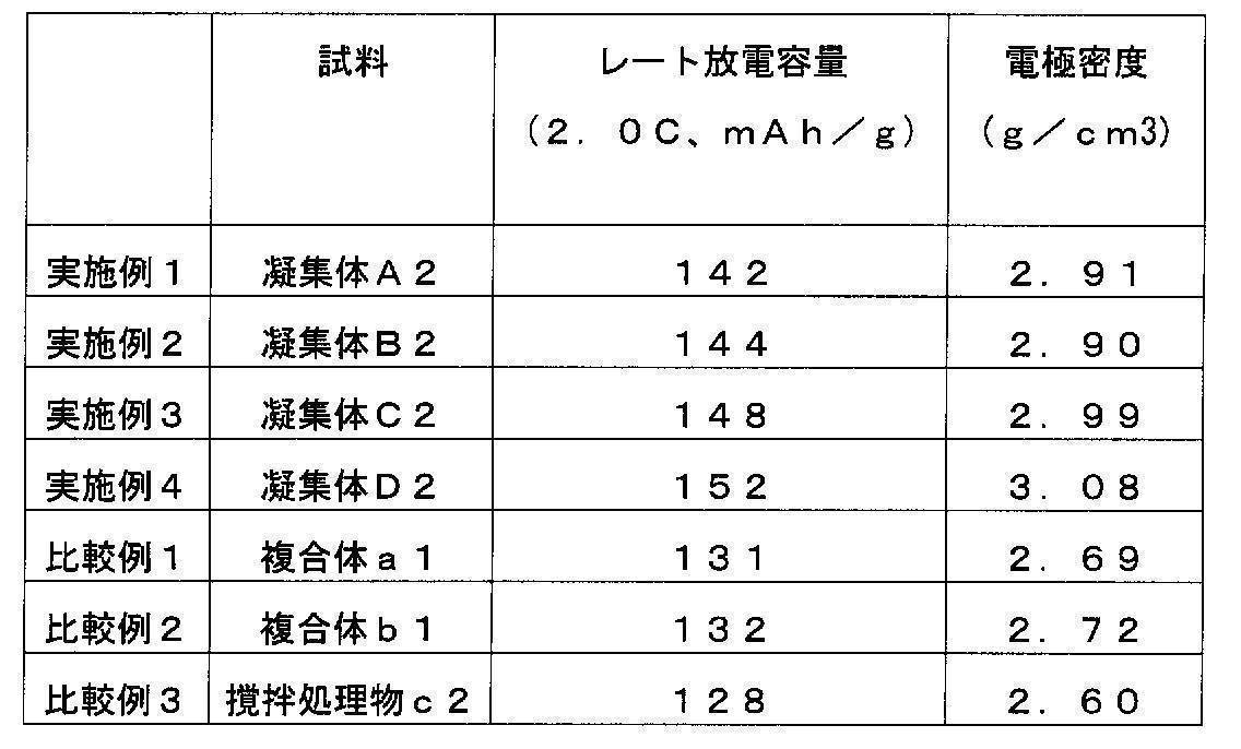
実施例1~4で得た凝集体(A2)、(B2)、(C2)、(D2)、比較例1~2で得た複合体(a1)、(b1)又は比較例3で得た撹拌処理物(c2)77重量%、ケッチェンブラック粉末8重量%、ポリフッ化ビニリデン15重量%を混合して正極剤とし、これをN-メチル-2-ピロリジノンに分散させて混練ペーストを調製した。該混練ペーストをアルミ箔に塗布したのち乾燥、プレスして直径15mmの円盤に打ち抜いて正極板を得た。
この正極板を用いて、セパレーター、負極、正極、集電板、取り付け金具、外部端子、電解液等の各部材を使用してリチウム二次電池を製作した。このうち、負極は金属リチウム箔を用い、電解液にはエチレンカーボネートとジエチルカーボネートの1:1混練液1リットルにLiPF61モルを溶解したものを使用した。
作製したリチウム二次電池を室温で作動させ、レート放電容量を測定して電池性能を評価した。
正極に対してCCCV(0.5C)で4.2Vまで充電した後、2.0Vまで(0.1C)放電させて、それを10サイクル繰り返した後に、CCCV(0.5C)で4.2Vまで充電し、2.0Vまで(2.0C)放電させ、その時の放電容量をレート放電容量とした。その結果を表4に示した。
(I)で直径15mmの円盤に打ち抜いて得た正極板の厚さと重量を測り、その電極密度を計算した。
2 導電性炭素材料
3 複合体
5 導電性炭素材料
10 凝集体
Claims (12)
- 下記一般式(1):
LiMPO4 (1)
(式中、MはFe、Mn、Co、Ni及びVの群から選ばれる1種以上の金属元素を示す。)で表わされるリチウムリン系複合酸化物粒子が導電性炭素材料を介して凝集している凝集体であり、該凝集体の平均粒子径が1~30μmであり、該凝集体のタップ密度が0.8g/cm3以上であることを特徴とするリチウムリン系複合酸化物炭素複合体。 - 前記凝集体中の前記導電性炭素材料の含有量が、炭素原子換算で、0.5~10質量%であることを特徴とする請求項1記載のリチウムリン系複合酸化物炭素複合体。
- 前記凝集体中の前記一般式(1)で表わされるリチウムリン系複合酸化物粒子の平均粒子径が、10~500nmであることを特徴とする請求項1又は2いずれか1項記載のリチウムリン系複合酸化物炭素複合体。
- 電極密度が2.8g/cm3以上であることを特徴とする請求項1~3いずれか1項記載のリチウムリン系複合酸化物炭素複合体。
- BET比表面積が10m2/g以上であることを特徴とする請求項1~4いずれか1項記載のリチウムリン系複合酸化物炭素複合体。
- リチウム源と、リン源と、Fe、Mn、Co、Ni及びVの群から選ばれる1種以上の金属元素(M金属元素)源と、導電性炭素材料源と、を混合し、原料混合物(a)を得る原料混合工程(a)と、該原料混合物(a)を加圧成型して、該原料混合物(a)の加圧成型体を得る加圧成型工程(a)と、該原料混合物(a)の加圧成型体を、不活性ガス雰囲気中、500~900℃で焼成して、下記一般式(1):
LiMPO4 (1)
(式中、MはFe、Mn、Co、Ni及びVの群から選ばれる1種以上の金属元素を示す。)で表わされるリチウムリン系複合酸化物粒子が導電性炭素材料で被覆されている複合体(a)を得る焼成工程(a)と、凝集体の平均粒子径が1~30μm且つタップ密度が0.8g/cm3以上となるまで、該複合体(a)をメカノケミカル処理して、前記一般式(1)で表わされるリチウムリン系複合酸化物粒子が導電性炭素材料介して凝集している凝集体(a)を得る造粒工程(a)と、を有することを特徴とするリチウムリン系複合酸化物炭素複合体の製造方法。 - リチウム源と、リン源と、Fe、Mn、Co、Ni及びVの群から選ばれる1種以上の金属元素(M金属元素)源と、導電性炭素材料の前駆体と、を混合し、第1原料混合物(b1)を得る第1原料混合工程(b)と、該第1原料混合物(b1)に、導電性炭素材料を混合して、第2原料混合物(b2)を得る第2原料混合工程(b)と、該第2原料混合物(b2)を加圧成型して、該第2原料混合物(b2)の加圧成型体を得る加圧成型工程(b)と、該第2原料混合物(b2)の加圧成型体を、不活性ガス雰囲気中、500~900℃で焼成して、下記一般式(1):
LiMPO4 (1)
(式中、MはFe、Mn、Co、Ni及びVの群から選ばれる1種以上の金属元素を示す。)で表わされるリチウムリン系複合酸化物粒子が導電性炭素材料で被覆されている複合体(b)を得る焼成工程(b)と、凝集体の平均粒子径が1~30μm且つタップ密度が0.8g/cm3以上となるまで、該複合体(b)をメカノケミカル処理して、下記一般式(1)で表わされるリチウムリン系複合酸化物粒子が導電性炭素材料を介して凝集している凝集体(b)を得る造粒工程(b)と、を有することを特徴とするリチウムリン系複合酸化物炭素複合体の製造方法。 - リチウム源と、リン源と、Fe、Mn、Co、Ni及びVの群から選ばれる1種以上の金属元素(M金属元素)源と、導電性炭素材料の前駆体と、を混合し、原料混合物(c)を得る原料混合工程(c)と、該原料混合物(c)を加圧成型して、該原料混合物(c)の加圧成型体を得る加圧成型工程(c)と、該原料混合物(c)の加圧成型体を、不活性ガス雰囲気中、500~900℃で焼成して、下記一般式(1):
LiMPO4 (1)
(式中、MはFe、Mn、Co、Ni及びVの群から選ばれる1種以上の金属元素を示す。)で表わされるリチウムリン系複合酸化物粒子が導電性炭素材料で被覆されている複合体(c)を得る焼成工程(c)と、該複合体(c)に、更に、導電性炭素材料を混合し、次いで、凝集体の平均粒子径が1~30μm且つタップ密度が0.8g/cm3以上となるまで、該複合体(c)と該導電性炭素材料との混合物をメカノケミカル処理して、前記一般式(1)で表わされるリチウムリン系複合酸化物粒子が導電性炭素材料を介して凝集している凝集体(c)を得る造粒工程(c)と、を有することを特徴とするリチウムリン系複合酸化物炭素複合体の製造方法。 - 前記導電性炭素材料の前駆体が、糖類であることを特徴とする請求項7又は8いずれか1項記載のリチウムリン系複合酸化物炭素複合体の製造方法。
- 前記造粒工程のメカノケミカル処理を、被処理物に圧縮力とせん断力とを作用させる機械的手段により行うことを特徴とする請求項6~9いずれか1項記載のリチウムリン系複合酸化物炭素複合体の製造方法。
- 請求項1~5いずれか1項記載のリチウムリン系複合酸化物炭素複合体を含むことを特徴とするリチウム二次電池用正極活物質。
- 請求項1~5いずれか1項記載のリチウムリン系複合酸化物炭素複合体を、リチウム二次電池用正極活物質として用いることを特徴とするリチウム二次電池。
Priority Applications (2)
| Application Number | Priority Date | Filing Date | Title |
|---|---|---|---|
| US13/255,204 US20120015249A1 (en) | 2009-03-17 | 2010-03-17 | Lithium phosphorus complex oxide-carbon composite, method for producing same, positive electrode active material for lithium secondary battery, and lithium secondary battery |
| CN2010800127765A CN102356489A (zh) | 2009-03-17 | 2010-03-17 | 锂磷系复合氧化物碳复合体、其制造方法、锂二次电池用正极活性物质及锂二次电池 |
Applications Claiming Priority (2)
| Application Number | Priority Date | Filing Date | Title |
|---|---|---|---|
| JP2009-064284 | 2009-03-17 | ||
| JP2009064284A JP5436896B2 (ja) | 2009-03-17 | 2009-03-17 | リチウムリン系複合酸化物炭素複合体、その製造方法、リチウム二次電池用正極活物質及びリチウム二次電池 |
Publications (1)
| Publication Number | Publication Date |
|---|---|
| WO2010107039A1 true WO2010107039A1 (ja) | 2010-09-23 |
Family
ID=42739699
Family Applications (1)
| Application Number | Title | Priority Date | Filing Date |
|---|---|---|---|
| PCT/JP2010/054486 Ceased WO2010107039A1 (ja) | 2009-03-17 | 2010-03-17 | リチウムリン系複合酸化物炭素複合体、その製造方法、リチウム二次電池用正極活物質及びリチウム二次電池 |
Country Status (5)
| Country | Link |
|---|---|
| US (1) | US20120015249A1 (ja) |
| JP (1) | JP5436896B2 (ja) |
| KR (1) | KR20110139220A (ja) |
| CN (1) | CN102356489A (ja) |
| WO (1) | WO2010107039A1 (ja) |
Cited By (3)
| Publication number | Priority date | Publication date | Assignee | Title |
|---|---|---|---|---|
| JP5155498B2 (ja) * | 2011-04-28 | 2013-03-06 | 昭和電工株式会社 | リチウム二次電池用正極活物質の製造方法 |
| CN103250280A (zh) * | 2010-12-17 | 2013-08-14 | 艾利电力能源有限公司 | 非水电解液二次电池用正极及非水电解液二次电池以及电池模块 |
| JP2015143189A (ja) * | 2015-04-23 | 2015-08-06 | 日亜化学工業株式会社 | オリビン型リチウム遷移金属酸化物及びその製造方法 |
Families Citing this family (31)
| Publication number | Priority date | Publication date | Assignee | Title |
|---|---|---|---|---|
| US9139429B2 (en) * | 2010-03-02 | 2015-09-22 | Guiqing Huang | High performance cathode material LiFePO4, its precursors and methods of making thereof |
| WO2011118350A1 (en) * | 2010-03-26 | 2011-09-29 | Semiconductor Energy Laboratory Co., Ltd. | Power storage device |
| JP5740708B2 (ja) * | 2010-12-17 | 2015-06-24 | エリーパワー株式会社 | 非水電解液二次電池用正極及び非水電解液二次電池並びに電池モジュール |
| JP2012133895A (ja) * | 2010-12-17 | 2012-07-12 | Eliiy Power Co Ltd | 非水電解液二次電池及び電池モジュール |
| CN103270628B (zh) | 2010-12-17 | 2016-06-29 | 住友大阪水泥股份有限公司 | 电极材料及其制造方法 |
| CN102683674A (zh) * | 2011-02-28 | 2012-09-19 | 黄桂清 | 纳米磷酸铁前驱体以及超细纳米电极材料磷酸铁锂的制备方法 |
| JP5718111B2 (ja) * | 2011-03-16 | 2015-05-13 | 古河電気工業株式会社 | リチウム遷移金属シリケート系正極活物質材料及び非水電解質2次電池用正極の製造方法 |
| JP5851707B2 (ja) * | 2011-04-01 | 2016-02-03 | 三井造船株式会社 | リン酸鉄リチウム正極材料およびその製造方法 |
| JP2013032257A (ja) * | 2011-06-28 | 2013-02-14 | Nichia Corp | オリビン型リチウム遷移金属酸化物及びその製造方法 |
| JP5621740B2 (ja) * | 2011-09-22 | 2014-11-12 | 住友大阪セメント株式会社 | 電極材料及び電極並びに電極材料の製造方法 |
| US9105928B2 (en) | 2011-11-25 | 2015-08-11 | Samsung Sdi Co., Ltd. | Positive active material for rechargeable lithium battery, method of preparing same, and rechargeable lithium battery including same |
| FR2988225B1 (fr) * | 2012-03-13 | 2014-03-28 | Hutchinson | Anode pour cellule de batterie lithium-ion, son procede de fabrication et cette batterie l'incorporant. |
| JP5478693B2 (ja) * | 2012-03-23 | 2014-04-23 | 太平洋セメント株式会社 | 二次電池用正極活物質及びその製造方法 |
| JP2013222664A (ja) * | 2012-04-18 | 2013-10-28 | Mitsui Chemicals Inc | リチウムイオン電池正極、および該正極を含む電池 |
| JP6241911B2 (ja) | 2012-11-13 | 2017-12-06 | 日東電工株式会社 | 活物質粒子、蓄電デバイス用正極、蓄電デバイスおよび活物質粒子の製造方法 |
| JP6020131B2 (ja) * | 2012-12-19 | 2016-11-02 | 日亜化学工業株式会社 | オリビン型リチウム遷移金属複合酸化物の製造方法 |
| JP6028630B2 (ja) * | 2013-03-12 | 2016-11-16 | ソニー株式会社 | 二次電池用活物質、二次電池用電極、二次電池、電池パック、電動車両、電力貯蔵システム、電動工具および電子機器 |
| JP2014179291A (ja) | 2013-03-15 | 2014-09-25 | Sumitomo Osaka Cement Co Ltd | 電極材料及び電極並びにリチウムイオン電池 |
| JP6394391B2 (ja) * | 2013-05-23 | 2018-09-26 | 東レ株式会社 | ポリアニオン系正極活物質複合体粒子の製造方法 |
| US20150147660A1 (en) * | 2013-11-26 | 2015-05-28 | Samsung Electronics Co., Ltd. | All solid secondary battery and method of preparing all solid secondary battery |
| CN107078284A (zh) * | 2014-05-21 | 2017-08-18 | 通用汽车环球科技运作有限责任公司 | 在锂电池组电极中的活性材料上分布导电性炭黑 |
| JP6042513B2 (ja) | 2015-03-24 | 2016-12-14 | 太平洋セメント株式会社 | 二次電池用正極活物質及びその製造方法 |
| WO2016151890A1 (ja) | 2015-03-24 | 2016-09-29 | 太平洋セメント株式会社 | 二次電池用正極活物質及びその製造方法 |
| EP3353844B1 (en) | 2015-03-27 | 2022-05-11 | Mason K. Harrup | All-inorganic solvents for electrolytes |
| EP3242300B1 (en) * | 2015-03-31 | 2025-09-03 | Murata Manufacturing Co., Ltd. | Lithium ion conductor, solid electrolyte layer, electrode, battery and electronic device |
| CN105304881A (zh) * | 2015-12-01 | 2016-02-03 | 中南大学 | 一种锂离子电池磷酸盐基复合正极材料及其制备方法 |
| US10707531B1 (en) | 2016-09-27 | 2020-07-07 | New Dominion Enterprises Inc. | All-inorganic solvents for electrolytes |
| CN110447127A (zh) * | 2017-03-20 | 2019-11-12 | 罗伯特·博世有限公司 | 电极活性材料、制备所述电极活性材料的方法以及包含所述电极活性材料的正极和电池 |
| CN107154494A (zh) * | 2017-05-26 | 2017-09-12 | 河南圣起机械集团有限公司 | 一种磷酸铁锂正极材料的制备方法 |
| US20220396497A1 (en) * | 2019-10-31 | 2022-12-15 | Panasonic Intellectual Property Management Co., Ltd. | Method for producing lithium transition metal composite oxide |
| CN112563469A (zh) * | 2020-12-09 | 2021-03-26 | 中南大学 | 一种新型三相复合正极材料及其制备方法 |
Citations (7)
| Publication number | Priority date | Publication date | Assignee | Title |
|---|---|---|---|---|
| JP2003292309A (ja) * | 2002-01-31 | 2003-10-15 | Nippon Chem Ind Co Ltd | リチウム鉄リン系複合酸化物炭素複合体、その製造方法、リチウム二次電池正極活物質及びリチウム二次電池 |
| JP2003292308A (ja) * | 2002-01-31 | 2003-10-15 | Nippon Chem Ind Co Ltd | リチウム鉄リン系複合酸化物炭素複合体、その製造方法、リチウム二次電池正極活物質及びリチウム二次電池 |
| JP2006032241A (ja) * | 2004-07-21 | 2006-02-02 | Mitsui Mining Co Ltd | リチウムイオン二次電池用正極材料、その製造方法、及びリチウムイオン二次電池 |
| JP2006347805A (ja) * | 2005-06-15 | 2006-12-28 | Seimi Chem Co Ltd | リチウム鉄複合酸化物の製造方法 |
| JP2007022894A (ja) * | 2005-07-21 | 2007-02-01 | Seimi Chem Co Ltd | リチウム鉄複合酸化物の製造方法 |
| JP2007230784A (ja) * | 2004-03-30 | 2007-09-13 | Agc Seimi Chemical Co Ltd | リチウム鉄複合酸化物の製造方法 |
| JP2009004371A (ja) * | 2007-05-21 | 2009-01-08 | Toda Kogyo Corp | 非水電解質二次電池用オリビン型複合酸化物及びその製造方法、並びに二次電池 |
Family Cites Families (7)
| Publication number | Priority date | Publication date | Assignee | Title |
|---|---|---|---|---|
| JP3611134B2 (ja) * | 1994-11-11 | 2005-01-19 | 日本電池株式会社 | 非水系リチウム電池用正極活物質およびその製造方法 |
| US5910382A (en) * | 1996-04-23 | 1999-06-08 | Board Of Regents, University Of Texas Systems | Cathode materials for secondary (rechargeable) lithium batteries |
| JP2001076727A (ja) * | 1999-09-08 | 2001-03-23 | Sony Corp | 非水電解質電池用正極活物質及び非水電解質電池 |
| JP4491946B2 (ja) * | 2000-09-29 | 2010-06-30 | ソニー株式会社 | 正極活物質の製造方法及び非水電解質電池の製造方法 |
| TW513822B (en) * | 2000-10-06 | 2002-12-11 | Sony Corp | Method for producing cathode active material and method for producing non-aqueous electrolyte cell |
| JP4529432B2 (ja) * | 2003-12-08 | 2010-08-25 | 日産自動車株式会社 | リチウムイオン電池用正極材料およびこれを用いた電池 |
| KR100670507B1 (ko) * | 2005-04-28 | 2007-01-16 | 삼성에스디아이 주식회사 | 리튬 이차 전지 |
-
2009
- 2009-03-17 JP JP2009064284A patent/JP5436896B2/ja active Active
-
2010
- 2010-03-17 US US13/255,204 patent/US20120015249A1/en not_active Abandoned
- 2010-03-17 KR KR1020117021503A patent/KR20110139220A/ko not_active Ceased
- 2010-03-17 CN CN2010800127765A patent/CN102356489A/zh active Pending
- 2010-03-17 WO PCT/JP2010/054486 patent/WO2010107039A1/ja not_active Ceased
Patent Citations (7)
| Publication number | Priority date | Publication date | Assignee | Title |
|---|---|---|---|---|
| JP2003292309A (ja) * | 2002-01-31 | 2003-10-15 | Nippon Chem Ind Co Ltd | リチウム鉄リン系複合酸化物炭素複合体、その製造方法、リチウム二次電池正極活物質及びリチウム二次電池 |
| JP2003292308A (ja) * | 2002-01-31 | 2003-10-15 | Nippon Chem Ind Co Ltd | リチウム鉄リン系複合酸化物炭素複合体、その製造方法、リチウム二次電池正極活物質及びリチウム二次電池 |
| JP2007230784A (ja) * | 2004-03-30 | 2007-09-13 | Agc Seimi Chemical Co Ltd | リチウム鉄複合酸化物の製造方法 |
| JP2006032241A (ja) * | 2004-07-21 | 2006-02-02 | Mitsui Mining Co Ltd | リチウムイオン二次電池用正極材料、その製造方法、及びリチウムイオン二次電池 |
| JP2006347805A (ja) * | 2005-06-15 | 2006-12-28 | Seimi Chem Co Ltd | リチウム鉄複合酸化物の製造方法 |
| JP2007022894A (ja) * | 2005-07-21 | 2007-02-01 | Seimi Chem Co Ltd | リチウム鉄複合酸化物の製造方法 |
| JP2009004371A (ja) * | 2007-05-21 | 2009-01-08 | Toda Kogyo Corp | 非水電解質二次電池用オリビン型複合酸化物及びその製造方法、並びに二次電池 |
Cited By (3)
| Publication number | Priority date | Publication date | Assignee | Title |
|---|---|---|---|---|
| CN103250280A (zh) * | 2010-12-17 | 2013-08-14 | 艾利电力能源有限公司 | 非水电解液二次电池用正极及非水电解液二次电池以及电池模块 |
| JP5155498B2 (ja) * | 2011-04-28 | 2013-03-06 | 昭和電工株式会社 | リチウム二次電池用正極活物質の製造方法 |
| JP2015143189A (ja) * | 2015-04-23 | 2015-08-06 | 日亜化学工業株式会社 | オリビン型リチウム遷移金属酸化物及びその製造方法 |
Also Published As
| Publication number | Publication date |
|---|---|
| US20120015249A1 (en) | 2012-01-19 |
| CN102356489A (zh) | 2012-02-15 |
| KR20110139220A (ko) | 2011-12-28 |
| JP5436896B2 (ja) | 2014-03-05 |
| JP2010218884A (ja) | 2010-09-30 |
Similar Documents
| Publication | Publication Date | Title |
|---|---|---|
| JP5436896B2 (ja) | リチウムリン系複合酸化物炭素複合体、その製造方法、リチウム二次電池用正極活物質及びリチウム二次電池 | |
| JP4187524B2 (ja) | リチウム鉄リン系複合酸化物炭素複合体、その製造方法、リチウム二次電池正極活物質及びリチウム二次電池 | |
| JP4187523B2 (ja) | リチウム鉄リン系複合酸化物炭素複合体、その製造方法、リチウム二次電池正極活物質及びリチウム二次電池 | |
| JP7118374B2 (ja) | 複合負極活物質、それを含む負極及びリチウム二次電池、並びに該複合負極活物質の製造方法 | |
| KR101342601B1 (ko) | 음극 활물질, 그 제조방법 및 이를 포함하는 리튬 전지 | |
| JP5871543B2 (ja) | 改質リン酸バナジウムリチウム炭素複合体、その製造方法、リチウム二次電池正極活物質及びリチウム二次電池 | |
| US20160156031A1 (en) | Anode active material for lithium secondary battery and lithium secondary battery including the anode active material | |
| WO2019093094A1 (ja) | 炭素被覆Li5FeO4 | |
| CN102668187A (zh) | 锂二次电池用正极活性物质、其制造方法和锂二次电池 | |
| JP4968872B2 (ja) | リチウム二次電池正極活物質、その製造方法及びリチウム二次電池 | |
| JP2012074366A (ja) | コバルト酸リチウム、その製造方法、リチウム二次電池用正極活物質及びリチウム二次電池 | |
| JP2013182757A (ja) | リチウム二次電池用正極活物質、その製造方法及びリチウム二次電池 | |
| JP7027824B2 (ja) | 炭素被覆Li5FeO4 | |
| JP2009295465A (ja) | リチウム二次電池用正極活物質及びその製造方法 | |
| JP2019085314A (ja) | 炭素被覆Li5FeO4 | |
| US20130059201A1 (en) | Negative-electrode active substance for electricity storage device, and negative electrode material for electricity storage device and negative electrode for electricity storage device which use the same | |
| KR20230025342A (ko) | 리튬 이차 전지용 양극 활물질, 이의 제조 방법 및 이를 포함하는 리튬 이차 전지 | |
| KR102176590B1 (ko) | 리튬 이차전지용 음극 활물질의 제조방법 및 리튬 이차전지 | |
| WO2019031543A1 (ja) | 二次電池用負極活物質および二次電池 | |
| JP2015130324A (ja) | 非水電解液二次電池 | |
| KR20110108301A (ko) | 비수 전해질 이차 전지 및 비수 전해질 이차 전지의 제조 방법 | |
| JP2024524173A (ja) | 負極活物質、その製造方法およびこれを含むリチウム二次電池 | |
| KR101696902B1 (ko) | 활물질, 그 제조방법, 이를 포함하는 전극 및 이를 포함한 이차 전지 | |
| KR20170074624A (ko) | 양극 활물질, 이를 채용한 리튬 전지, 및 상기 양극 활물질의 제조방법 | |
| US11349113B2 (en) | Method of producing iron phosphide, positive electrode for lithium secondary battery comprising iron phosphide, and lithium secondary battery comprising same |
Legal Events
| Date | Code | Title | Description |
|---|---|---|---|
| WWE | Wipo information: entry into national phase |
Ref document number: 201080012776.5 Country of ref document: CN |
|
| 121 | Ep: the epo has been informed by wipo that ep was designated in this application |
Ref document number: 10753531 Country of ref document: EP Kind code of ref document: A1 |
|
| ENP | Entry into the national phase |
Ref document number: 20117021503 Country of ref document: KR Kind code of ref document: A |
|
| NENP | Non-entry into the national phase |
Ref country code: DE |
|
| WWE | Wipo information: entry into national phase |
Ref document number: 13255204 Country of ref document: US |
|
| 122 | Ep: pct application non-entry in european phase |
Ref document number: 10753531 Country of ref document: EP Kind code of ref document: A1 |