WO2010098030A1 - 溶接方法および溶接システム - Google Patents
溶接方法および溶接システム Download PDFInfo
- Publication number
- WO2010098030A1 WO2010098030A1 PCT/JP2010/000927 JP2010000927W WO2010098030A1 WO 2010098030 A1 WO2010098030 A1 WO 2010098030A1 JP 2010000927 W JP2010000927 W JP 2010000927W WO 2010098030 A1 WO2010098030 A1 WO 2010098030A1
- Authority
- WO
- WIPO (PCT)
- Prior art keywords
- welding
- electrode
- single electrode
- welding robot
- robot system
- Prior art date
Links
- 238000003466 welding Methods 0.000 title claims abstract description 473
- 238000000034 method Methods 0.000 title claims description 41
- 238000009941 weaving Methods 0.000 claims description 44
- 238000012937 correction Methods 0.000 claims description 37
- 239000000463 material Substances 0.000 claims description 21
- 238000012545 processing Methods 0.000 description 25
- 238000010586 diagram Methods 0.000 description 10
- 230000006870 function Effects 0.000 description 9
- 230000036544 posture Effects 0.000 description 8
- 238000004891 communication Methods 0.000 description 6
- 239000011324 bead Substances 0.000 description 4
- 101001095043 Homo sapiens Bone marrow proteoglycan Proteins 0.000 description 2
- 101001131990 Homo sapiens Peroxidasin homolog Proteins 0.000 description 2
- 101000582986 Homo sapiens Phospholipid phosphatase-related protein type 3 Proteins 0.000 description 2
- 102100030383 Phospholipid phosphatase-related protein type 3 Human genes 0.000 description 2
- 238000013459 approach Methods 0.000 description 2
- 238000004519 manufacturing process Methods 0.000 description 2
- 238000005259 measurement Methods 0.000 description 1
- 230000002093 peripheral effect Effects 0.000 description 1
Images


Classifications
-
- B—PERFORMING OPERATIONS; TRANSPORTING
- B23—MACHINE TOOLS; METAL-WORKING NOT OTHERWISE PROVIDED FOR
- B23K—SOLDERING OR UNSOLDERING; WELDING; CLADDING OR PLATING BY SOLDERING OR WELDING; CUTTING BY APPLYING HEAT LOCALLY, e.g. FLAME CUTTING; WORKING BY LASER BEAM
- B23K9/00—Arc welding or cutting
- B23K9/095—Monitoring or automatic control of welding parameters
- B23K9/0953—Monitoring or automatic control of welding parameters using computing means
-
- B—PERFORMING OPERATIONS; TRANSPORTING
- B23—MACHINE TOOLS; METAL-WORKING NOT OTHERWISE PROVIDED FOR
- B23K—SOLDERING OR UNSOLDERING; WELDING; CLADDING OR PLATING BY SOLDERING OR WELDING; CUTTING BY APPLYING HEAT LOCALLY, e.g. FLAME CUTTING; WORKING BY LASER BEAM
- B23K9/00—Arc welding or cutting
- B23K9/02—Seam welding; Backing means; Inserts
- B23K9/0216—Seam profiling, e.g. weaving, multilayer
-
- B—PERFORMING OPERATIONS; TRANSPORTING
- B23—MACHINE TOOLS; METAL-WORKING NOT OTHERWISE PROVIDED FOR
- B23K—SOLDERING OR UNSOLDERING; WELDING; CLADDING OR PLATING BY SOLDERING OR WELDING; CUTTING BY APPLYING HEAT LOCALLY, e.g. FLAME CUTTING; WORKING BY LASER BEAM
- B23K33/00—Specially-profiled edge portions of workpieces for making soldering or welding connections; Filling the seams formed thereby
- B23K33/004—Filling of continuous seams
-
- B—PERFORMING OPERATIONS; TRANSPORTING
- B23—MACHINE TOOLS; METAL-WORKING NOT OTHERWISE PROVIDED FOR
- B23K—SOLDERING OR UNSOLDERING; WELDING; CLADDING OR PLATING BY SOLDERING OR WELDING; CUTTING BY APPLYING HEAT LOCALLY, e.g. FLAME CUTTING; WORKING BY LASER BEAM
- B23K9/00—Arc welding or cutting
- B23K9/02—Seam welding; Backing means; Inserts
- B23K9/025—Seam welding; Backing means; Inserts for rectilinear seams
- B23K9/0256—Seam welding; Backing means; Inserts for rectilinear seams for welding ribs on plates
-
- B—PERFORMING OPERATIONS; TRANSPORTING
- B23—MACHINE TOOLS; METAL-WORKING NOT OTHERWISE PROVIDED FOR
- B23K—SOLDERING OR UNSOLDERING; WELDING; CLADDING OR PLATING BY SOLDERING OR WELDING; CUTTING BY APPLYING HEAT LOCALLY, e.g. FLAME CUTTING; WORKING BY LASER BEAM
- B23K9/00—Arc welding or cutting
- B23K9/12—Automatic feeding or moving of electrodes or work for spot or seam welding or cutting
-
- B—PERFORMING OPERATIONS; TRANSPORTING
- B23—MACHINE TOOLS; METAL-WORKING NOT OTHERWISE PROVIDED FOR
- B23K—SOLDERING OR UNSOLDERING; WELDING; CLADDING OR PLATING BY SOLDERING OR WELDING; CUTTING BY APPLYING HEAT LOCALLY, e.g. FLAME CUTTING; WORKING BY LASER BEAM
- B23K9/00—Arc welding or cutting
- B23K9/16—Arc welding or cutting making use of shielding gas
- B23K9/173—Arc welding or cutting making use of shielding gas and of a consumable electrode
- B23K9/1735—Arc welding or cutting making use of shielding gas and of a consumable electrode making use of several electrodes
-
- B—PERFORMING OPERATIONS; TRANSPORTING
- B23—MACHINE TOOLS; METAL-WORKING NOT OTHERWISE PROVIDED FOR
- B23K—SOLDERING OR UNSOLDERING; WELDING; CLADDING OR PLATING BY SOLDERING OR WELDING; CUTTING BY APPLYING HEAT LOCALLY, e.g. FLAME CUTTING; WORKING BY LASER BEAM
- B23K2101/00—Articles made by soldering, welding or cutting
- B23K2101/18—Sheet panels
Definitions
- the present invention relates to a welding method and welding system using a plurality of welding robot systems and simultaneously welding to one welding line using welding electrodes mounted thereon.
- tandem welding dedicated torch The two-electrode integrated torch, or two single-electrode torches fixedly arranged in proximity to each other, are collectively referred to as "tandem welding dedicated torch" for convenience of the following description.
- a tandem welding dedicated torch is mounted on a welding robot and a welding system configured with necessary equipment applies tandem welding to a welding process in actual production (see, for example, Patent Document 1).
- tandem arc welding was adopted to achieve high efficiency, and a torch dedicated to tandem welding was used. It occurs because it is mounted. This creates a situation where the number of weldable parts is reduced.
- the original purpose of introducing welding robots is to save labor and automate. However, if a portion that can not be welded remains, it can not but be manually welded. Then, the proportion of parts that can be automated is reduced, and the proportion relied on human hands is increased, resulting in a situation contrary to the original purpose.
- the position of each electrode is relatively determined with respect to the weld line of the weld joint to be welded. Therefore, the range in which the position of each electrode can be adjusted is narrow.
- the two electrodes since the two electrodes only have to move (move) in the same manner, they have been a constraint for properly performing the welding required for the joint to be welded.
- the present invention provides a welding method and a welding system in which a plurality of robots are not constrained in their degrees of freedom, and the weldable range is not narrowed.
- the welding method of the present invention is a welding method in which welding is performed using a plurality of welding robots that perform welding using a single electrode, wherein a single electrode is moved by one welding robot and another electrode is moved by another welding robot.
- the single electrode of one welding robot and the single electrode of another welding robot simultaneously perform welding on the same welding line in the same direction.
- a manipulator for holding a welding torch for a single electrode, a control device for controlling the operation of the manipulator based on a previously stored operation program, and a welding wire having a single electrode.
- a welding system comprising a plurality of welding robot systems comprising a welding power supply for supplying electric power to an object to be welded, wherein the welding robot further moves a single electrode by one manipulator of one welding robot system. The movement of the single electrode by the manipulator of the system is made to follow, and the single electrode of one manipulator and the single electrode of the other manipulator perform welding simultaneously in the same direction on the same welding line.
- the plurality of robots can determine the position and the posture of their own single electrode in an optimum posture, and the degree of freedom of the robot is not restricted compared to the case of using a torch dedicated to tandem welding, and welding is possible. There is no need to narrow the scope. For this reason, restrictions on the posture of the robot are eliminated.
- FIG. 1 is a view showing a schematic configuration of a welding system according to a first embodiment of the present invention.
- FIG. 2 is a diagram showing the operation of the consumable welding electrode in the first embodiment of the present invention.
- FIG. 3 is a diagram showing an example of a program according to the first embodiment of the present invention.
- FIG. 4 is a diagram showing a flow of interpolation processing according to Embodiment 1 of the present invention.
- FIG. 5 is a diagram showing another operation of the consumable welding electrode in the first embodiment of the present invention.
- FIG. 6 is a diagram showing another example of the program in the first embodiment of the present invention.
- FIG. 7 is a view showing a specific example of welding in the first embodiment of the present invention.
- FIG. 1 is a view showing a schematic configuration of a welding system according to a first embodiment of the present invention.
- FIG. 2 is a diagram showing the operation of the consumable welding electrode in the first embodiment of the present invention.
- FIG. 3 is a diagram showing
- FIG. 8A is a diagram showing a flow of weaving processing in the second embodiment of the present invention.
- FIG. 8B is a diagram showing a flow of weaving processing in the second embodiment of the present invention.
- FIG. 9 is a view showing a specific example of welding in the second embodiment of the present invention.
- FIG. 10 is a view showing another specific example of welding in the second embodiment of the present invention.
- FIG. 11A is a diagram showing a flow of arc sensor processing in the third embodiment of the present invention.
- FIG. 11B is a diagram showing a flow of arc sensor processing in the third embodiment of the present invention.
- FIG. 1 is a view showing a schematic configuration of a welding system in the present embodiment.
- FIG. 1 shows an example in which two welding robot systems having the same equipment are used.
- the connection method of welding robot systems mutually may differ depending on the specification of the apparatus to comprise, and the structure of FIG. 1 is an example to the last.
- FIG. 1 shows an example in which two welding robot systems are provided for the sake of convenience of the description, the present invention is not necessarily limited to two welding robots systems, and may be composed of three or more welding robot systems. It is possible.
- a moving device for mounting a manipulator to move the position of the manipulator In a practical welding system, a moving device for mounting a manipulator to move the position of the manipulator, a positioner for mounting a base material to be welded and changing its posture, a jig for mounting the base material, etc.
- a positioner for mounting a base material to be welded and changing its posture In many cases.
- the description of the present embodiment is not a necessary element, and is omitted here to simplify the description.
- one welding robot system is referred to as a, and the reference numeral of each part of the welding robot system a is given a subscript a.
- the other welding robot system is referred to as b, and the reference numerals of the respective parts of the welding robot system b are given a subscript b.
- the two welding robot systems will now be described separately.
- the welding robot system a includes a manipulator 11a and a welding power supply 12a.
- the cable 123a is connected to the torch terminal 121a provided in the welding power supply 12a.
- a base material W is connected to a base material terminal 122a provided in the welding power supply 12a.
- the wire feeding device 14a is attached to the manipulator 11a.
- the operation of the manipulator 11a is controlled by the control device 10a.
- the touch sensor unit 13a is used, the cable 123a is connected to the feed terminal 141a provided in the wire feeding device 14a via the touch sensor unit 13a.
- the cable 123a is directly connected to the feed terminal 141a when the touch sensor unit 13a is not used.
- the wire feeding device 14a and the single electrode welding torch 16a are connected by a torch cable 15a.
- a consumable welding electrode 18a which is a welding wire, passes through the torch cable 15a.
- the cable 124a whose one end is connected to the base material W which is the object to be welded is connected to the base material terminal 122a provided at the other end of the welding power supply 12a.
- the consumable welding electrode 18a is continuously fed to the base material W by controlling the wire feeding device 14a by the welding power source device 12a. Then, the control of the operation of the manipulator 11a by the control device 10a causes the consumable welding electrode 18a to move along the welding line of the base material W. This results in arc welding.
- the control device 10a controls the operation of the manipulator 11a based on an operation program stored in advance in a memory (not shown). Further, the control device 10a gives the welding power supply 12a a command such as a welding current or a welding voltage. The welding power supply 12a controls the welding current and the welding voltage according to the command.
- Arc sensor 17a adds predetermined processing to the measurement data according to the request of control device 10a to the welding current / welding voltage measured inside of welding power supply device 12a or at any part of the circuit of the welding current described above. It is converted into data corresponding to the deviation from the weld line and sent to the control device 10a.
- the control device 10a controls the operation of the manipulator 11a based on the data corresponding to the received deviation from the weld line, and corrects the deviation from the weld line.
- the arc sensor 17a is not necessarily used, but is used in the present embodiment.
- Welding robot system b performs welding on a base material W common to welding robot system a, and has the same configuration as welding robot system a. Therefore, the description of the individual devices constituting the welding robot system b is omitted.
- control device 10 a and the control device 10 b are connected by an inter-robot communication cable X.
- arcs are generated in both consumable welding electrodes 18a and 18b while moving in the welding advancing direction. That is, in the configuration of FIG. 1, for example, in the movement of the consumable welding electrode 18a in the single electrode welding torch 16a by the manipulator 11a of one welding robot system a, the single electrode welding torch 16b by the manipulator 11b of the other welding robot system b.
- the movement of the inner consumable welding electrode 18a is made to follow.
- the two arcs of the arc generated between consumable welding electrode 18a and base material W and the arc generated between consumable welding electrode 18b and base material W form one molten pool while welding is performed. Do. Thereby, welding such as conventional tandem welding can be performed.
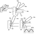
- FIG. 2 is a diagram showing the operation of the consumable welding electrode in the present embodiment.
- FIG. 2 a case will be described in which welding robot system a shown in FIG. 1 precedes in the welding direction and welding robot system b follows in the welding direction.
- P210, P211, P212 and P213 are time-series programmed positions of the consumable welding electrode 18a and the consumable welding electrode 18b before and after welding of a welding wire when welding one welding wire. Is shown.
- the consumable welding electrode 18a and the consumable welding electrode 18b move along the welding line L at the welding speed designated as the welding condition.
- both welding robot systems end welding. Thereafter, the welding wire L retracts from the welding line L, and as shown at P213, the consumable welding electrode 18a and the consumable welding electrode 18b move to separate positions in the air.
- An example of an operation program for performing such an operation is shown in FIG. 3 as PRG2.
- the program is stored, for example, in the control device 10a or the control device 10b.
- the command L201 instructs the consumable welding electrode 18a and the consumable welding electrode 18b to move to the position indicated by P210.
- the instruction L202 is for designating welding conditions to be used when performing welding.
- the command L203 instructs the consumable welding electrode 18a and the consumable welding electrode 18b to move to the position indicated by P211.
- the command L204 instructs the consumable welding electrode 18a, which is a leading electrode, to start welding.
- the instruction L205 instructs the consumable welding electrode 18b, which is a trailing electrode, to start welding.
- the command L206 instructs the two consumable welding electrodes 18a and 18b to move to the position indicated by P212.
- the command L207 instructs the consumable welding electrode 18a, which is a leading electrode, to end welding.
- the instruction L208 specifies that the consumable welding electrode 18b, which is a trailing electrode, ends welding.
- the command L209 instructs the consumable welding electrode 18a and the consumable welding electrode 18b to move to the position indicated by
- P ⁇ b> 210, P ⁇ b> 211, P ⁇ b> 212, and P ⁇ b> 213 represent teaching points programmed as the operation of the welding robot.
- Each teaching point is made up of data necessary for specifying the positions of the consumable welding electrode 18a and the consumable welding electrode 18b.
- coordinate values (X, Y, Z) of the consumable welding electrode in an orthogonal coordinate system referred to as a robot coordinate system
- Euler angles ⁇ , ⁇ , ⁇
- the position data of those is included.
- any representation form may be used in the present embodiment.
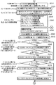
- the interpolation processing is performed when the interpolation start position is the position of P211 shown in FIG. 2 and the end position is P212 shown in FIG. As described above, here, P211 is the welding start position, and P212 is the welding end position.
- the process performed according to the flowchart shown in FIG. 4 is performed by one control device, and the welding robot system is called a master, and the other welding robot system is called a slave.
- parameters such as programs and welding conditions are stored in a memory (not shown) of the master control device.
- the difference between the master and the slave is the difference between the role of mainly performing control and the role of following. However, if it is decided in advance, either welding robot system or master or slave should be made Can. And, there is no need to make an essential difference in the specifications of the device.
- welding robot system a is described as a master, and welding robot system b as a slave.
- the master in terms of welding control, it does not matter whether the master is leading or trailing as long as it is fixed. This can be set by an instruction in the program, but if it is not the default, the master will lead. Here, it is assumed that the preceding is the master, that is, the welding robot system a.
- Steps S010 to S290 are shown as the process of the flowchart shown in FIG.
- the parameters such as the program and the welding conditions are read from the memory (not shown) to proceed the process, and the two welds shown on the right side of FIG. It issues an operation command to the drive system of the robot system.
- the welding conditions read from the memory are a master teaching point, a slave teaching point, a welding current, a welding voltage, a welding wire feeding speed, and the like.
- the operation command to the drive system of the welding robot system is output to the drive mechanism of the master robot and the drive mechanism of the slave robot.
- an initial calculation necessary for the slave's interpolation operation is performed (S020).
- the total number of interpolations N is performed as a given value. Thereby, the interpolation operations of the master and the slave are performed during the same total number of interpolations, that is, during the same time.
- the interpolation position is calculated between S050 and S070.
- the interpolation position of the master is calculated using the updated number of interpolations and the result of the interpolation initial calculation previously obtained (S060). Thereafter, the interpolation position of the slave is calculated in the same manner (S070).
- the interpolation position of the master calculated in S060 is output as a drive command to the drive mechanism of the master robot (S260).
- the slave's interpolation position calculated in S070 is output as a drive command to the slave's drive mechanism (S270).
- a command to the drive mechanism of the welding robot system b which is a slave is sent from the master to the slave via an inter-robot communication cable X.
- the slave receives it and operates its own drive system according to the command.
- the interpolation counter n is larger than the total number of interpolations N (S280). If the interpolation counter n is not larger than the total number of interpolations N, ie, if the interpolation counter n is less than the total number of interpolations N (S280 No), return to S050 and repeat the interpolation calculation. Thereby, the operation toward the welding end position (P212) is realized sequentially from the welding start position (P221).
- interpolation counter n is the total number of interpolations N at S280 (Yes at S280), processing is performed when the end position is reached, and the interpolation operation as one unit is ended (S290).
- welding control is performed before, after, and during this one unit interpolation operation.
- welding control according to the setting contents of welding conditions specified by the instruction in the program, welding start / end command, as shown on the left side of FIG. 4, welding current / welding voltage command, welding wire feed speed Command etc. to the welding power supply.
- the command to the welding power supply 12b of the welding robot system b which is a slave is a robot It is sent from the master (welding robot system a) to the slave (welding robot system b) through the inter-communication cable X.
- the slave receives it and commands the welding power supply 12b according to the command.
- FIG. 5 Another operation example in the present embodiment is shown in FIG. 5, and an example of the program is shown in FIG. The main difference from the cases of FIGS. 2 and 3 is that the simultaneous welding with both electrodes and the welding with only one of the electrodes are switched.
- P1010, P1011, P1012, P1013, P1014, and P1015 are time-series programmed positions of consumable welding electrode 18a and consumable welding electrode 18b before and after welding with respect to one welding line L. Is shown.
- consumable welding electrode 18a reaches welding line L
- consumable welding electrode 18b reaches the air in the vicinity of welding line L.
- consumable welding electrode 18a starts welding to generate an arc.
- welding is advanced only with the consumable welding electrode 18a, and the consumable welding electrode 18a and the consumable welding electrode 18b approach each other on the welding line L at P1012.
- consumable welding electrode 18b also starts welding to generate an arc.
- the consumable welding electrode 18a and the consumable welding electrode 18b move to separate distant positions in the air.
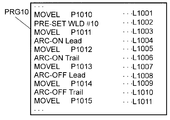
- PRG 10 An example of an operation program for performing such an operation is shown as PRG 10 in FIG. This program is stored, for example, in the control device 10a.
- a command L1001 instructs the consumable welding electrode 18a and the consumable welding electrode 18b to move to positions indicated by P1010, respectively.
- the instruction L1002 designates welding conditions to be used when performing welding.
- the command L1003 instructs the consumable welding electrode 18a and the consumable welding electrode 18b to move to the position indicated by P1011.
- the command L1004 instructs the consumable welding electrode 18a, which is a leading electrode, to start welding.
- the command L1005 instructs the consumable welding electrode 18a and the consumable welding electrode 18b to move to the position indicated by P1012.
- the command L1006 instructs the consumable welding electrode 18b, which is a trailing electrode, to start welding.
- the command L1007 instructs the two consumable welding electrodes 18a and 18b to move to the position indicated by P1013.
- the command L1008 instructs the consumable welding electrode 18a, which is a leading electrode, to end welding.
- the command L1009 instructs that the two consumable electrodes of the consumable welding electrode 18a and the consumable welding electrode 18b move to the position indicated by P1014.
- the command L1010 instructs the consumable welding electrode 18b, which is a trailing electrode, to finish welding.
- the instruction L1011 instructs the consumable welding electrode 18a and the consumable welding electrode 18b to move to the position indicated by P1015. As described above, as can be seen from FIG. 5, the coordinates of the positions of the consumable welding electrode 18a and the consumable welding electrode 18b are different from each other.
- the welding control performed before, after, and in the middle is, for example, the welding start / end command and the welding current / welding voltage command to the welding power supply 12a according to the setting contents of the welding conditions specified by the command in the program It is realized by sending.
- the two consumable welding electrodes 18a and 18b of the two welding robot systems a and b are arranged at a certain distance and in close proximity to each other. It can be operated.
- one pool and two arc welding can be performed using two welding robot systems a and b, as in the conventional tandem arc welding method.
- each teaching point contains data (coordinate values (X, Y, Z) and Euler angles necessary to specify the positions of the two consumable welding electrodes 18a, 18b. ( ⁇ , ⁇ , ⁇ ), etc.), and it is also possible to have different optimal postures. For this reason, the degree of freedom of the robot is not restricted as compared with the case where a torch dedicated to tandem welding is used, and the weldable range is not narrowed. This eliminates restrictions on the robot's attitude.
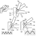
- FIG. 7 shows the case of welding a fillet welded joint having a beveled groove. It is assumed that it is necessary to put a fillet weld bead of a certain leg length on the groove portion G1.
- the first consumable welding electrode 18a performs the first welding W1 of the groove portion G1
- the second consumable welding electrode 18b performs the second welding W2 of the fillet portion.
- a bead shape close to a flat shape is to be obtained by increasing the inclination of the following consumable welding electrode 18b with respect to the consumable welding electrode 18a.
- welding can be performed with one of the two welding robot systems a and b, so the overall automation rate does not decrease. It's over.
- the welding method and welding system in the present embodiment use a standard welding robot system that performs welding with a single electrode without using special equipment such as a torch for tandem welding and a mounting mechanism for two-torch welding. It was As described above, since it is configured by a standard device, it is easy to obtain replacement parts and the like inexpensively, and maintainability is good.
- the area around the torch is compact compared to using special equipment such as a tandem welding torch and a mounting mechanism for two-torch welding. Therefore, when using a torch for tandem welding or a mounting mechanism for two-torch welding, welding can be performed at a portion where welding could not be performed because it hits a peripheral member or the like at the welding position, which is highly convenient. .
- a welding system with a high degree of freedom can be constructed.
- welding with single electrodes and tandem welding can be realized depending on the object to be welded and the welding portion, which is very useful.
- a command L202 designates welding conditions to be used in welding.
- a weaving operation is performed by specifying a combination of welding speed, welding current and welding voltage of leading electrode and trailing electrode, weaving parameters in case of performing weaving operation, and the like.
- the welding method and welding system of the present embodiment use two welding robot systems a and b as shown in FIG. You can specify separate values in.
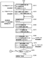
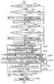
- FIGS. 8A and 8B show flowcharts in the case of performing weaving control using different weaving parameters for the leading electrode and the trailing electrode.
- S010 to S290 are shown.
- the program and parameters such as welding conditions are read from the memory (not shown) as shown on the left side of the flowchart of FIG. 8A to advance the processing, and as shown on the right side of the flowchart of FIG.
- An operation command is issued to the drive system.
- FIG. 8A and FIG. 8B first, using the teaching points of the master registered in the operation program, and the welding speed specified as the welding conditions, etc., perform the initial calculation necessary for the interpolation operation of the master (S010) . In this calculation, the total number of interpolations N is calculated. Further, the interpolation counter n which counts the number of subsequent interpolation position calculations is reset to zero.
- an initial calculation necessary for the slave's interpolation operation is performed (S020).
- the total number of interpolations N is performed as a given value. Thereby, the interpolation operations of the master and the slave are performed during the same total number of interpolations, that is, during the same time.
- a set of weaving parameters that is, a weaving parameter for the leading electrode and a weaving parameter for the trailing electrode are read from the memory (not shown) of the control devices 10a and 10b (S030).
- the initial initial calculation of the weaving of the master and the initial calculation of the weaving of the slave are performed (S040).
- the preceding weaving parameters are assigned to the master and the subsequent weaving parameters to the slave.
- the weaving initial calculation is a process of determining the calculation formula of the number of interpolations Mm and Ms per pitch of the master and the slave, and the weaving component for each interpolation. In this calculation, the one-pitch interpolation counter mm, ms in each of the master and slave is reset to zero.
- the interpolation position is calculated between S050 and S070.
- the interpolation position of the master is calculated using the updated number of interpolations and the result of the interpolation initial calculation previously obtained (S060). Further, the interpolation position of the slave is similarly calculated (S070).
- S140 it is determined whether or not there is weaving of the master (S140). If there is no weaving of the master at S140 (No at S140), the process jumps to the weaving process of the slave from S180. When there is weaving of the master in S140 (Yes in S140), it is determined whether it is in the middle of one pitch (S150). If it is in the middle of one pitch in S150 (Yes in S150), the process jumps to S170, and the weaving component for each interpolation position is calculated according to the weld line direction already obtained in S160.
- the welding line direction is recalculated (S160) in order to shift to a new weaving pitch, so that the welding line direction changes for each pitch such as arc. Thereafter, the weaving component for each interpolation position is calculated (S170).
- S180 it is determined whether or not there is weaving of the slave (S180). If there is no weaving of the slave at S180 (No at S180), the process jumps to the process of determining the designated position from S220. If there is slave weaving at S180 (Yes at S180), it is determined whether it is in the middle of one pitch (S190). If it is in the middle of one pitch in S190 (Yes in S190), the process jumps to S210 to calculate the weaving component for each interpolation position in accordance with the weld line direction already obtained in S200.
- the welding line direction is recalculated (S200) in order to shift to a new weaving pitch, so that the welding line direction changes for each pitch such as arc. Thereafter, the weaving component for each interpolation position is calculated (S210).
- the weaving component at the interpolation position of the master is added to the interpolation position of the master to obtain the command position of the master (S220).
- the weaving component at the slave's interpolation position is added to the slave's interpolation position to obtain the slave's command position (S250).
- a master servo command is issued by outputting a command position of the master to the drive mechanism of the master (S260).
- a slave servo command is issued by outputting a command position of the slave to the drive mechanism of the slave (S270).
- the interpolation counter n is the total number of interpolations N (S280). If the interpolation counter n is less than the total number N of interpolations at S280 (No at S280), the process returns to S050 and repeats the interpolation calculation. Thereby, an operation is sequentially realized from the start position toward the end position.
- the interpolation counter n is the total number of interpolations N at S280 (YES in S280)
- the processing at the end position position is performed, and the interpolation operation as one unit is ended (S290).
- FIG. 9 shows the case of a fillet-welded joint having a beveled groove, and it is assumed that it is necessary to place a fillet-welded bead of a fixed leg length on the groove portion G2.
- the first consumable welding electrode 18a performs the first welding W1 of the groove portion G2
- the second consumable welding electrode 18b performs the second welding W2 of the fillet portion.
- the preceding consumable welding electrode 18a for welding the groove G2 performs weaving WVa with a small amplitude.
- the trailing consumable welding electrode 18b performs weaving WVb with a large amplitude and inclination with respect to the preceding consumable welding electrode 18a. This welds a fillet bead close to a flat surface.
- weaving may be performed in both of the leading and trailing sides, or only one of the weaving may be performed.
- the preceding consumable welding electrode 16a is not woven, and the trailing edge It is also possible to select only the consumable welding electrode 16b of FIG.
- Embodiment 1 and Embodiment 2 will be assigned the same reference numerals and names, and detailed descriptions thereof will be omitted.
- the main point in which the present embodiment differs from the first embodiment and the second embodiment is that the arc sensor function is utilized.
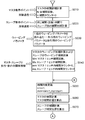
- data corresponding to the deviation from the weld line is sent to the control devices 10a and 10b using the arc sensors 17a and 17b shown in FIG. 11A and 11B show flowcharts in the case of performing control using the arc sensor function.
- the program and parameters such as welding conditions are read from a memory (not shown) to advance the process, and as shown on the right side of the flowchart of FIG. A command is issued to the a and b drive systems.
- S010 to S070 are the same as FIG. 8A and FIG. Steps S080 to S115 are arc sensor processing. During this time, processing is performed by reading parameters such as welding conditions for the arc sensor from a memory (not shown).
- a memory not shown.
- the master leads as in the case of FIGS. 8A and 8B.
- welding robot system a is a master and welding robot system b is a slave.
- parameters such as welding conditions regarding the arc sensor of the master are read, and it is determined whether the arc sensor of the master is valid or invalid (S080). If the master's arc sensor is invalid at S080 (No at S080), the process jumps to the slave's arc sensor determination at S100. If the master's arc sensor is valid in S080 (Yes in S080), data corresponding to the deviation from the master's weld line is read from the master's arc sensor, and processing is performed to calculate the correction of the master's position. That is, the master locus correction by the arc sensor of the master is calculated (S085).
- parameters such as welding conditions regarding the arc sensor of the slave are read, and it is determined whether the arc sensor of the slave is valid or invalid (S100). If the arc sensor of the slave is invalid at S100 (No at S100), the processing of the arc sensor relationship is ended, and the process jumps to the processing of S140.
- S100 when the arc sensor of the slave is valid (Yes in S100), the control device 10b of the slave reads data corresponding to the deviation from the weld line of the slave from the arc sensor of the slave. Further, the read data is sent from the slave to the master via the robot communication cable X, and the master calculates the correction of the slave position. That is, slave trajectory correction by the arc sensor of the slave is calculated (S105).
- the slave trajectory correction by the arc sensor of the slave is reflected on the master, that is, whether the arc sensor correction of the slave is also used by the master (S110). If the slave locus correction by the arc sensor of the slave is not reflected on the master in S110, that is, if the arc sensor correction of the slave is not used even by the master (No in S110), the processing of the arc sensor ends and the process jumps to the processing of S140. Do.
- each of the welding robot systems a and b performs the arc sensor function.
- each of the plurality of welding robot systems may perform the arc sensor function.
- one of the two welding robot systems a and b performs the arc sensor function to obtain correction information and corrects the welding position, and the other welding robot system performs one of the welding robots
- the correction information may be acquired from the system and the welding position may be corrected based on the correction information.
- one or more of the plurality of welding robots perform the arc sensor function, and each of the one or more welding robots performs correction information by the arc sensor function, and each welding robot performs a single electrode Correct the position.
- another welding robot that does not perform the arc sensor function obtains correction information from the welding robot that performs one or more arc sensors, and corrects the position of the single electrode with respect to the welding line based on the correction information. It may be one.
- welding is performed by causing the welding robot system of the slave to follow the master and perform welding, so welding can be performed in any combination of a plurality of welding robot systems.
- the efficiency of the entire system can be improved.
- the welding method and welding system of the present invention can increase the efficiency of the entire system, and therefore, is industrially useful as a welding method and welding system for performing high welding by using a plurality of welding robot systems.
Priority Applications (5)
| Application Number | Priority Date | Filing Date | Title |
|---|---|---|---|
| JP2011501477A JP4831264B2 (ja) | 2009-02-25 | 2010-02-16 | 溶接方法および溶接システム |
| EP10745917.4A EP2314406A4 (en) | 2009-02-25 | 2010-02-16 | WELDING METHOD AND WELDING SYSTEM |
| US13/003,673 US20110301733A1 (en) | 2009-02-25 | 2010-02-16 | Welding method and welding system |
| CN2010800026270A CN102159355A (zh) | 2009-02-25 | 2010-02-16 | 焊接方法和焊接系统 |
| US13/687,128 US20130087542A1 (en) | 2009-02-25 | 2012-11-28 | Welding system |
Applications Claiming Priority (2)
| Application Number | Priority Date | Filing Date | Title |
|---|---|---|---|
| JP2009-041952 | 2009-02-25 | ||
| JP2009041952 | 2009-02-25 |
Related Child Applications (1)
| Application Number | Title | Priority Date | Filing Date |
|---|---|---|---|
| US13/687,128 Division US20130087542A1 (en) | 2009-02-25 | 2012-11-28 | Welding system |
Publications (1)
| Publication Number | Publication Date |
|---|---|
| WO2010098030A1 true WO2010098030A1 (ja) | 2010-09-02 |
Family
ID=42665247
Family Applications (1)
| Application Number | Title | Priority Date | Filing Date |
|---|---|---|---|
| PCT/JP2010/000927 WO2010098030A1 (ja) | 2009-02-25 | 2010-02-16 | 溶接方法および溶接システム |
Country Status (5)
| Country | Link |
|---|---|
| US (2) | US20110301733A1 (zh) |
| EP (1) | EP2314406A4 (zh) |
| JP (3) | JP4831264B2 (zh) |
| CN (1) | CN102159355A (zh) |
| WO (1) | WO2010098030A1 (zh) |
Cited By (2)
| Publication number | Priority date | Publication date | Assignee | Title |
|---|---|---|---|---|
| KR101301832B1 (ko) * | 2011-12-29 | 2013-08-29 | 주식회사 한진중공업 | 동기화된 듀얼 필렛 자동 용접 장치 |
| US10737346B2 (en) | 2016-03-23 | 2020-08-11 | Kobe Steel, Ltd. | Welding robot mechanism |
Families Citing this family (13)
| Publication number | Priority date | Publication date | Assignee | Title |
|---|---|---|---|---|
| WO2010098030A1 (ja) * | 2009-02-25 | 2010-09-02 | パナソニック株式会社 | 溶接方法および溶接システム |
| JP5843683B2 (ja) * | 2012-03-28 | 2016-01-13 | 株式会社神戸製鋼所 | タンデム溶接トーチ |
| CN102672315B (zh) * | 2012-06-07 | 2014-07-02 | 中国东方电气集团有限公司 | 一种自主移动式双面双弧焊接机器人系统 |
| WO2014148032A1 (ja) * | 2013-03-19 | 2014-09-25 | パナソニック株式会社 | ロボットシステムの制御方法およびロボットシステム |
| MX359889B (es) * | 2013-07-09 | 2018-10-15 | Weld Revolution Llc | Aparato y método para su utilización en un proceso de soldadura por arco rotatorio. |
| WO2015139116A1 (en) * | 2014-03-17 | 2015-09-24 | Bombardier Transportation Gmbh | Hybrid laser welding system and method using two robots |
| JP5829313B1 (ja) * | 2014-06-25 | 2015-12-09 | ファナック株式会社 | シミュレーションを用いたオフライン教示装置 |
| JP5995220B2 (ja) | 2014-07-11 | 2016-09-21 | インターナショナル・ビジネス・マシーンズ・コーポレーションInternational Business Machines Corporation | メッセージを処理する装置及び方法 |
| CN107921634B (zh) * | 2015-08-25 | 2021-04-02 | 川崎重工业株式会社 | 机器人系统 |
| JP2017196653A (ja) * | 2016-04-28 | 2017-11-02 | 株式会社神戸製鋼所 | ガスシールドアーク溶接システム及びガスシールドアーク溶接方法 |
| JP2019147181A (ja) * | 2018-02-28 | 2019-09-05 | トヨタ自動車株式会社 | パルスアーク溶接方法 |
| US11311958B1 (en) * | 2019-05-13 | 2022-04-26 | Airgas, Inc. | Digital welding and cutting efficiency analysis, process evaluation and response feedback system for process optimization |
| JP6915183B1 (ja) * | 2021-02-04 | 2021-08-04 | 株式会社システムサポート | セキュリティ検査システムおよび、セキュリティ検査方法 |
Citations (6)
| Publication number | Priority date | Publication date | Assignee | Title |
|---|---|---|---|---|
| JPS5841680A (ja) * | 1981-09-04 | 1983-03-10 | Kobe Steel Ltd | 厚肉パイプ突合わせタンデム溶接装置 |
| JPH0919766A (ja) * | 1995-07-06 | 1997-01-21 | Japan Steel & Tube Constr Co Ltd | 管接続用溶接装置 |
| JPH09253845A (ja) * | 1996-03-25 | 1997-09-30 | Tokyo Gas Co Ltd | 2ヘッド式円周自動溶接装置のヘッド運行方法 |
| JPH09295136A (ja) * | 1996-05-01 | 1997-11-18 | Mitsubishi Heavy Ind Ltd | 鋼管の積層式溶接方法 |
| JPH11342473A (ja) * | 1998-05-29 | 1999-12-14 | Daihen Corp | Tig溶接用ロボットの制御方法 |
| JP4089755B2 (ja) | 2006-06-14 | 2008-05-28 | 松下電器産業株式会社 | タンデムアーク溶接装置 |
Family Cites Families (42)
| Publication number | Priority date | Publication date | Assignee | Title |
|---|---|---|---|---|
| US3197604A (en) * | 1962-04-04 | 1965-07-27 | Union Tank Car Co | Method and apparatus for welding |
| US3832523A (en) * | 1972-04-17 | 1974-08-27 | Osaka Transformer Co Ltd | Method for electrical arc welding |
| JPS5853375A (ja) * | 1981-09-24 | 1983-03-29 | Kobe Steel Ltd | 消耗電極式ア−ク溶接方法 |
| JPS58112661A (ja) * | 1981-12-26 | 1983-07-05 | Nippon Kokan Kk <Nkk> | ア−ク溶接方法 |
| JPS58212871A (ja) * | 1982-06-02 | 1983-12-10 | Shin Meiwa Ind Co Ltd | 産業用ロボツト |
| JPS6072677A (ja) * | 1983-09-29 | 1985-04-24 | Shin Meiwa Ind Co Ltd | 多層盛溶接方法 |
| CN85104150B (zh) * | 1985-06-04 | 1987-03-11 | 机械工业部哈尔滨焊接研究所 | 双丝窄间隙埋弧焊方法 |
| EP0512583B1 (en) * | 1986-03-20 | 1999-06-23 | Shin Meiwa Industry Co., Ltd. | Method of and apparatus for controlling a welding robot |
| US5155330A (en) * | 1991-08-02 | 1992-10-13 | The Lincoln Electric Company | Method and apparatus for GMAW welding |
| JPH0724571A (ja) * | 1993-07-13 | 1995-01-27 | Hitachi Ltd | イナートガスアーク溶接用トーチによる管と管板との自動溶接方法及び装置 |
| DE4436084A1 (de) * | 1994-10-10 | 1996-02-15 | Daimler Benz Ag | Anordnung zum Schmelzschweißen von Werkstücknähten mit mehreren Schweißbrennern |
| KR100200639B1 (ko) * | 1996-11-13 | 1999-06-15 | 윤종용 | 자동 용접장치의 용접토오치 경로 보정방법 |
| JP3169342B2 (ja) * | 1997-02-12 | 2001-05-21 | 川崎製鉄株式会社 | 横向き多層盛りの自動溶接方法 |
| US6207929B1 (en) * | 1999-06-21 | 2001-03-27 | Lincoln Global, Inc. | Tandem electrode welder and method of welding with two electrodes |
| GB9828727D0 (en) * | 1998-12-24 | 1999-02-17 | Saipem Spa | Apparatus and method for welding pipes together |
| US6172333B1 (en) * | 1999-08-18 | 2001-01-09 | Lincoln Global, Inc. | Electric welding apparatus and method |
| US6291798B1 (en) * | 1999-09-27 | 2001-09-18 | Lincoln Global, Inc. | Electric ARC welder with a plurality of power supplies |
| SE0001312D0 (sv) * | 2000-04-10 | 2000-04-10 | Abb Ab | Industrirobot |
| US6472634B1 (en) * | 2001-04-17 | 2002-10-29 | Lincoln Global, Inc. | Electric arc welding system |
| US6697701B2 (en) * | 2001-08-09 | 2004-02-24 | Lincoln Global, Inc. | Welding system and methodology providing multiplexed cell control interface |
| JP3577028B2 (ja) * | 2001-11-07 | 2004-10-13 | 川崎重工業株式会社 | ロボットの協調制御システム |
| DE10251600A1 (de) * | 2002-11-06 | 2004-05-27 | Kuka Roboter Gmbh | Verfahren und Vorrichtung zum Steuern von Bewegungen bei Handhabungsgeräten |
| JP3841757B2 (ja) * | 2003-01-23 | 2006-11-01 | ファナック株式会社 | アーク溶接ロボットのトーチケーブル処理構造 |
| US6804580B1 (en) * | 2003-04-03 | 2004-10-12 | Kuka Roboter Gmbh | Method and control system for controlling a plurality of robots |
| US6940039B2 (en) * | 2003-12-22 | 2005-09-06 | Lincoln Global, Inc. | Quality control module for tandem arc welding |
| JP3886497B2 (ja) * | 2004-03-12 | 2007-02-28 | ファナック株式会社 | 産業用ロボットのための線条体処理構造 |
| JP3867712B2 (ja) * | 2004-04-20 | 2007-01-10 | 松下電器産業株式会社 | 消耗電極アーク溶接方法 |
| US7166817B2 (en) * | 2004-04-29 | 2007-01-23 | Lincoln Global, Inc. | Electric ARC welder system with waveform profile control for cored electrodes |
| DE102004021389A1 (de) * | 2004-04-30 | 2005-11-24 | Daimlerchrysler Ag | Verfahren und Vorrichtung zum Verbinden von mindestens zwei Werkstücken |
| DE102004026813A1 (de) * | 2004-06-02 | 2005-12-29 | Kuka Roboter Gmbh | Verfahren und Vorrichtung zum Steuern von Handhabungsgeräten |
| JP2006099474A (ja) * | 2004-09-29 | 2006-04-13 | Fanuc Ltd | ロボットの軌跡制御方法 |
| CN100377827C (zh) * | 2005-01-08 | 2008-04-02 | 湘潭大学 | 埋弧焊焊缝自动跟踪控制方法 |
| US8680432B2 (en) * | 2005-04-20 | 2014-03-25 | Illinois Tool Works Inc. | Cooperative welding system |
| AT502283B1 (de) * | 2005-07-15 | 2007-05-15 | Fronius Int Gmbh | Schweissverfahren und schweisssystem mit bestimmung der position des schweissbrenners |
| CA2611243C (en) * | 2006-06-14 | 2010-02-02 | Matsushita Electric Industrial Co., Ltd. | Method of controlling arc welding |
| US10010961B2 (en) * | 2006-07-17 | 2018-07-03 | Lincoln Global, Inc. | Multiple arc welding system controls and methods |
| US8946596B2 (en) * | 2006-10-05 | 2015-02-03 | Lincoln Global, Inc. | Multiple welding using a single power source |
| JP4891726B2 (ja) * | 2006-10-06 | 2012-03-07 | 株式会社神戸製鋼所 | タンデムアーク溶接システムを制御するロボット制御装置およびそれを用いたアーク倣い制御方法 |
| CN101134260A (zh) * | 2007-10-25 | 2008-03-05 | 上海交通大学 | 三丝明弧焊接方法 |
| JP2009166076A (ja) * | 2008-01-15 | 2009-07-30 | Kobe Steel Ltd | 溶接ロボット |
| WO2010098030A1 (ja) * | 2009-02-25 | 2010-09-02 | パナソニック株式会社 | 溶接方法および溶接システム |
| JP5360237B2 (ja) * | 2010-02-03 | 2013-12-04 | パナソニック株式会社 | ロボットシステムの制御方法 |
-
2010
- 2010-02-16 WO PCT/JP2010/000927 patent/WO2010098030A1/ja active Application Filing
- 2010-02-16 JP JP2011501477A patent/JP4831264B2/ja not_active Expired - Fee Related
- 2010-02-16 EP EP10745917.4A patent/EP2314406A4/en not_active Withdrawn
- 2010-02-16 US US13/003,673 patent/US20110301733A1/en not_active Abandoned
- 2010-02-16 CN CN2010800026270A patent/CN102159355A/zh active Pending
-
2011
- 2011-04-14 JP JP2011089864A patent/JP4930646B2/ja not_active Expired - Fee Related
- 2011-04-14 JP JP2011089863A patent/JP4930645B2/ja not_active Expired - Fee Related
-
2012
- 2012-11-28 US US13/687,128 patent/US20130087542A1/en not_active Abandoned
Patent Citations (6)
| Publication number | Priority date | Publication date | Assignee | Title |
|---|---|---|---|---|
| JPS5841680A (ja) * | 1981-09-04 | 1983-03-10 | Kobe Steel Ltd | 厚肉パイプ突合わせタンデム溶接装置 |
| JPH0919766A (ja) * | 1995-07-06 | 1997-01-21 | Japan Steel & Tube Constr Co Ltd | 管接続用溶接装置 |
| JPH09253845A (ja) * | 1996-03-25 | 1997-09-30 | Tokyo Gas Co Ltd | 2ヘッド式円周自動溶接装置のヘッド運行方法 |
| JPH09295136A (ja) * | 1996-05-01 | 1997-11-18 | Mitsubishi Heavy Ind Ltd | 鋼管の積層式溶接方法 |
| JPH11342473A (ja) * | 1998-05-29 | 1999-12-14 | Daihen Corp | Tig溶接用ロボットの制御方法 |
| JP4089755B2 (ja) | 2006-06-14 | 2008-05-28 | 松下電器産業株式会社 | タンデムアーク溶接装置 |
Non-Patent Citations (1)
| Title |
|---|
| See also references of EP2314406A4 |
Cited By (2)
| Publication number | Priority date | Publication date | Assignee | Title |
|---|---|---|---|---|
| KR101301832B1 (ko) * | 2011-12-29 | 2013-08-29 | 주식회사 한진중공업 | 동기화된 듀얼 필렛 자동 용접 장치 |
| US10737346B2 (en) | 2016-03-23 | 2020-08-11 | Kobe Steel, Ltd. | Welding robot mechanism |
Also Published As
| Publication number | Publication date |
|---|---|
| EP2314406A4 (en) | 2015-04-22 |
| JP4831264B2 (ja) | 2011-12-07 |
| JP4930645B2 (ja) | 2012-05-16 |
| CN102159355A (zh) | 2011-08-17 |
| EP2314406A1 (en) | 2011-04-27 |
| JPWO2010098030A1 (ja) | 2012-08-30 |
| JP2011140071A (ja) | 2011-07-21 |
| JP4930646B2 (ja) | 2012-05-16 |
| US20130087542A1 (en) | 2013-04-11 |
| US20110301733A1 (en) | 2011-12-08 |
| JP2011140070A (ja) | 2011-07-21 |
Similar Documents
| Publication | Publication Date | Title |
|---|---|---|
| WO2010098030A1 (ja) | 溶接方法および溶接システム | |
| JP5360237B2 (ja) | ロボットシステムの制御方法 | |
| KR101060435B1 (ko) | 용접 로봇 | |
| JP4089755B2 (ja) | タンデムアーク溶接装置 | |
| KR101971496B1 (ko) | 아크용접 모니터 장치 | |
| WO2021256129A1 (ja) | 可搬型溶接ロボットの制御方法、溶接制御装置、可搬型溶接ロボット及び溶接システム | |
| EP3628430B1 (en) | Welding apparatus and welding method | |
| JP2014200858A (ja) | ロボットシステムの制御方法 | |
| JP2005254242A (ja) | 溶接システム | |
| JP7162178B2 (ja) | アーク溶接方法、アーク溶接システム、および溶接電源装置の制御装置 | |
| JP5670147B2 (ja) | アーク溶接ロボット制御装置 | |
| JP7272807B2 (ja) | 溶接装置および溶接方法 | |
| JP5077515B2 (ja) | 溶接ロボットシステム | |
| JP5051351B2 (ja) | アーク溶接装置 | |
| JP5163922B2 (ja) | ロボットの制御装置およびロボットの軌跡制御方法 | |
| JP2014087818A (ja) | アーク溶接方法およびアーク溶接装置 | |
| JP2005177796A (ja) | レーザ照射アーク溶接用加工ヘッドの移動制御方法 | |
| KR100695960B1 (ko) | 회전 위치별 용접 전류 데이터를 이용한 용접 부재의 끝단자동 인식 방법 | |
| WO2016199427A1 (ja) | 溶接システムおよび溶接方法 | |
| JP2008207274A (ja) | 工業用ロボット |
Legal Events
| Date | Code | Title | Description |
|---|---|---|---|
| WWE | Wipo information: entry into national phase |
Ref document number: 201080002627.0 Country of ref document: CN |
|
| 121 | Ep: the epo has been informed by wipo that ep was designated in this application |
Ref document number: 10745917 Country of ref document: EP Kind code of ref document: A1 |
|
| WWE | Wipo information: entry into national phase |
Ref document number: 2011501477 Country of ref document: JP |
|
| WWE | Wipo information: entry into national phase |
Ref document number: 2010745917 Country of ref document: EP |
|
| WWE | Wipo information: entry into national phase |
Ref document number: 13003673 Country of ref document: US |
|
| NENP | Non-entry into the national phase |
Ref country code: DE |