WO2010095710A1 - Led照明装置 - Google Patents
Led照明装置 Download PDFInfo
- Publication number
- WO2010095710A1 WO2010095710A1 PCT/JP2010/052531 JP2010052531W WO2010095710A1 WO 2010095710 A1 WO2010095710 A1 WO 2010095710A1 JP 2010052531 W JP2010052531 W JP 2010052531W WO 2010095710 A1 WO2010095710 A1 WO 2010095710A1
- Authority
- WO
- WIPO (PCT)
- Prior art keywords
- led
- lighting device
- locking
- led lighting
- pair
- Prior art date
- Legal status (The legal status is an assumption and is not a legal conclusion. Google has not performed a legal analysis and makes no representation as to the accuracy of the status listed.)
- Ceased
Links
Images








Classifications
-
- F—MECHANICAL ENGINEERING; LIGHTING; HEATING; WEAPONS; BLASTING
- F21—LIGHTING
- F21S—NON-PORTABLE LIGHTING DEVICES; SYSTEMS THEREOF; VEHICLE LIGHTING DEVICES SPECIALLY ADAPTED FOR VEHICLE EXTERIORS
- F21S8/00—Lighting devices intended for fixed installation
- F21S8/04—Lighting devices intended for fixed installation intended only for mounting on a ceiling or the like overhead structures
-
- F—MECHANICAL ENGINEERING; LIGHTING; HEATING; WEAPONS; BLASTING
- F21—LIGHTING
- F21S—NON-PORTABLE LIGHTING DEVICES; SYSTEMS THEREOF; VEHICLE LIGHTING DEVICES SPECIALLY ADAPTED FOR VEHICLE EXTERIORS
- F21S4/00—Lighting devices or systems using a string or strip of light sources
- F21S4/20—Lighting devices or systems using a string or strip of light sources with light sources held by or within elongate supports
- F21S4/28—Lighting devices or systems using a string or strip of light sources with light sources held by or within elongate supports rigid, e.g. LED bars
-
- F—MECHANICAL ENGINEERING; LIGHTING; HEATING; WEAPONS; BLASTING
- F21—LIGHTING
- F21V—FUNCTIONAL FEATURES OR DETAILS OF LIGHTING DEVICES OR SYSTEMS THEREOF; STRUCTURAL COMBINATIONS OF LIGHTING DEVICES WITH OTHER ARTICLES, NOT OTHERWISE PROVIDED FOR
- F21V13/00—Producing particular characteristics or distribution of the light emitted by means of a combination of elements specified in two or more of main groups F21V1/00 - F21V11/00
- F21V13/02—Combinations of only two kinds of elements
- F21V13/04—Combinations of only two kinds of elements the elements being reflectors and refractors
-
- F—MECHANICAL ENGINEERING; LIGHTING; HEATING; WEAPONS; BLASTING
- F21—LIGHTING
- F21V—FUNCTIONAL FEATURES OR DETAILS OF LIGHTING DEVICES OR SYSTEMS THEREOF; STRUCTURAL COMBINATIONS OF LIGHTING DEVICES WITH OTHER ARTICLES, NOT OTHERWISE PROVIDED FOR
- F21V17/00—Fastening of component parts of lighting devices, e.g. shades, globes, refractors, reflectors, filters, screens, grids or protective cages
- F21V17/10—Fastening of component parts of lighting devices, e.g. shades, globes, refractors, reflectors, filters, screens, grids or protective cages characterised by specific fastening means or way of fastening
- F21V17/107—Fastening of component parts of lighting devices, e.g. shades, globes, refractors, reflectors, filters, screens, grids or protective cages characterised by specific fastening means or way of fastening using hinge joints
-
- F—MECHANICAL ENGINEERING; LIGHTING; HEATING; WEAPONS; BLASTING
- F21—LIGHTING
- F21V—FUNCTIONAL FEATURES OR DETAILS OF LIGHTING DEVICES OR SYSTEMS THEREOF; STRUCTURAL COMBINATIONS OF LIGHTING DEVICES WITH OTHER ARTICLES, NOT OTHERWISE PROVIDED FOR
- F21V17/00—Fastening of component parts of lighting devices, e.g. shades, globes, refractors, reflectors, filters, screens, grids or protective cages
- F21V17/10—Fastening of component parts of lighting devices, e.g. shades, globes, refractors, reflectors, filters, screens, grids or protective cages characterised by specific fastening means or way of fastening
- F21V17/16—Fastening of component parts of lighting devices, e.g. shades, globes, refractors, reflectors, filters, screens, grids or protective cages characterised by specific fastening means or way of fastening by deformation of parts; Snap action mounting
- F21V17/164—Fastening of component parts of lighting devices, e.g. shades, globes, refractors, reflectors, filters, screens, grids or protective cages characterised by specific fastening means or way of fastening by deformation of parts; Snap action mounting the parts being subjected to bending, e.g. snap joints
-
- F—MECHANICAL ENGINEERING; LIGHTING; HEATING; WEAPONS; BLASTING
- F21—LIGHTING
- F21V—FUNCTIONAL FEATURES OR DETAILS OF LIGHTING DEVICES OR SYSTEMS THEREOF; STRUCTURAL COMBINATIONS OF LIGHTING DEVICES WITH OTHER ARTICLES, NOT OTHERWISE PROVIDED FOR
- F21V21/00—Supporting, suspending, or attaching arrangements for lighting devices; Hand grips
- F21V21/02—Wall, ceiling, or floor bases; Fixing pendants or arms to the bases
- F21V21/025—Elongated bases having a U-shaped cross section
-
- F—MECHANICAL ENGINEERING; LIGHTING; HEATING; WEAPONS; BLASTING
- F21—LIGHTING
- F21V—FUNCTIONAL FEATURES OR DETAILS OF LIGHTING DEVICES OR SYSTEMS THEREOF; STRUCTURAL COMBINATIONS OF LIGHTING DEVICES WITH OTHER ARTICLES, NOT OTHERWISE PROVIDED FOR
- F21V21/00—Supporting, suspending, or attaching arrangements for lighting devices; Hand grips
- F21V21/14—Adjustable mountings
- F21V21/30—Pivoted housings or frames
-
- F—MECHANICAL ENGINEERING; LIGHTING; HEATING; WEAPONS; BLASTING
- F21—LIGHTING
- F21V—FUNCTIONAL FEATURES OR DETAILS OF LIGHTING DEVICES OR SYSTEMS THEREOF; STRUCTURAL COMBINATIONS OF LIGHTING DEVICES WITH OTHER ARTICLES, NOT OTHERWISE PROVIDED FOR
- F21V23/00—Arrangement of electric circuit elements in or on lighting devices
- F21V23/003—Arrangement of electric circuit elements in or on lighting devices the elements being electronics drivers or controllers for operating the light source, e.g. for a LED array
- F21V23/007—Arrangement of electric circuit elements in or on lighting devices the elements being electronics drivers or controllers for operating the light source, e.g. for a LED array enclosed in a casing
- F21V23/009—Arrangement of electric circuit elements in or on lighting devices the elements being electronics drivers or controllers for operating the light source, e.g. for a LED array enclosed in a casing the casing being inside the housing of the lighting device
-
- F—MECHANICAL ENGINEERING; LIGHTING; HEATING; WEAPONS; BLASTING
- F21—LIGHTING
- F21V—FUNCTIONAL FEATURES OR DETAILS OF LIGHTING DEVICES OR SYSTEMS THEREOF; STRUCTURAL COMBINATIONS OF LIGHTING DEVICES WITH OTHER ARTICLES, NOT OTHERWISE PROVIDED FOR
- F21V3/00—Globes; Bowls; Cover glasses
-
- F—MECHANICAL ENGINEERING; LIGHTING; HEATING; WEAPONS; BLASTING
- F21—LIGHTING
- F21Y—INDEXING SCHEME ASSOCIATED WITH SUBCLASSES F21K, F21L, F21S and F21V, RELATING TO THE FORM OR THE KIND OF THE LIGHT SOURCES OR OF THE COLOUR OF THE LIGHT EMITTED
- F21Y2103/00—Elongate light sources, e.g. fluorescent tubes
- F21Y2103/10—Elongate light sources, e.g. fluorescent tubes comprising a linear array of point-like light-generating elements
-
- F—MECHANICAL ENGINEERING; LIGHTING; HEATING; WEAPONS; BLASTING
- F21—LIGHTING
- F21Y—INDEXING SCHEME ASSOCIATED WITH SUBCLASSES F21K, F21L, F21S and F21V, RELATING TO THE FORM OR THE KIND OF THE LIGHT SOURCES OR OF THE COLOUR OF THE LIGHT EMITTED
- F21Y2115/00—Light-generating elements of semiconductor light sources
- F21Y2115/10—Light-emitting diodes [LED]
Definitions
- the present invention relates to an LED illumination device that includes a plurality of LED chips and is used for, for example, indoor floor illumination or wall illumination.
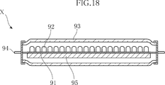
- FIG. 18 shows an example of a conventional LED lighting device in a cross-sectional view (see, for example, Patent Document 1).
- the LED lighting device X shown in the figure includes a long rectangular substrate 91, a plurality of LED chips 92 mounted on the substrate 91, a tube 93 that accommodates the substrate 91, a terminal 94, and the LED chip 92. And a circuit 95 for lighting.
- On the substrate 91 wirings (not shown) connected to the plurality of LED chips 92 and the terminals 94 are formed.
- the LED lighting device X is configured to emit light from a plurality of LED chips 92 by fitting the terminals 94 into sockets of a general fluorescent lamp lighting fixture.
- the general fluorescent lamp luminaire is a luminaire widely used mainly for indoor general lighting. For example, in Japan, a commercial 100V power source is used, and a straight tube fluorescent lamp defined in JIS C7617 or A lighting fixture to which a ring-shaped fluorescent lamp specified in JIS C7618 is attached.
- the lighting fixture using the conventional fluorescent lamp is configured on the premise that the terminals 94 exist at both ends thereof and emit light in the entire circumferential direction. For this reason, for example, when a plurality of LED lighting devices X are attached to a lighting fixture in which a plurality of fluorescent lamps are arranged in series, a dark portion that does not emit light is generated between the adjacent LED lighting devices X. Those who see it may feel it is not good looking. Or even if it is a case where it is a case where it is intended to illuminate a part of wall surface, if LED lighting apparatus X is used, light will be irradiated besides the location which wants to shine. For this reason, for example, it is forced to provide a light-shielding cover that covers the half circumference of the LED lighting device X. Japanese Utility Model Publication No. 6-54103
- the present invention has been conceived under the circumstances described above, and an object of the present invention is to provide an LED lighting device that can be used for various purposes.
- the LED lighting device provided by the present invention is characterized by comprising a plurality of LED chips, an LED unit on which the plurality of LED chips are mounted, and a mount for holding the LED unit.
- the LED unit has an elongated shape extending in a first direction, and the plurality of LED chips have a main emission direction along a second direction perpendicular to the first direction.
- the mount has a recess that opens in the second direction and accommodates the LED unit.
- the LED unit has a connector extending in a direction intersecting the first direction and connected to the LED unit, and the LED unit is the first of the mount.
- the size extends to both ends in the direction.
- the mount is provided with a holder having a locking piece for holding the LED unit, and the LED unit is fixed to engage with the locking piece.
- a locking groove is formed.
- the holder is disposed at a position sandwiching the LED unit in a third direction that is perpendicular to both the first and second directions, and the second
- the LED unit has a pair of locking pieces whose distance from each other in the third direction becomes smaller toward the opposite side in the emission direction of the plurality of LED chips.
- a pair of the locking grooves for fixing are provided on both sides in the direction.
- the holder has a flexible portion that can be elastically deformed so as to separate the pair of locking pieces from each other in the third direction.
- the LED unit has an elongated shape extending in a first direction, and is held so as to be rotatable around the first direction with respect to the mount.
- the plurality of LED chips have a main emission direction along a second direction perpendicular to the first direction.
- a pair of shafts each having a root portion and a tip portion that is rotatable with respect to the root portion are provided at both ends in the first direction of the LED unit.
- the mount is provided with a pair of holders having a fitting portion that fits into the tip portion.
- the pair of holders have flexible portions that can be elastically deformed so as to separate the fitting portions from each other in the first direction.
- the holder is positioned more inward in the first direction than the fitting portion, and the root portion is more than the portion of the shaft that fits the fitting portion.
- a hook-shaped portion that is locked to the other portion is formed.
- the LED unit has a U-shaped cross-section that has a portion that supports the plurality of LED chips as a bottom and opens in the second direction on the opposite side to the emission direction of the plurality of LED chips.
- a support member having a shape.
- the support member houses a power conversion unit that converts received power into output power for supplying the plurality of LED chips.
- the support member is attached to a bracket having a U-shaped cross-section and to the outside of the bottom of the bracket, and the plurality of LED chips are mounted. It is composed of a strip-shaped substrate having a longitudinal direction and a width direction of a third direction which is perpendicular to both the first and second directions.
- the bracket covers a U-shaped base portion to which the substrate is attached, at least a part of the base portion, and both end edges in the third direction of the substrate, And an outer portion exposing the plurality of LED chips.
- the LED unit further includes a cover that transmits light from the plurality of LED chips while diffusing.
- the cover has a belt-like shape extending in the first direction, and on both side edges in the third direction that is perpendicular to both the first direction and the second direction.
- a pair of locking pieces is formed, and the support member is provided with a pair of cover locking grooves that engage with the pair of locking pieces.
- one of the pair of locking pieces has a step portion that shifts an end portion thereof inward in the third direction, and the other is on the second direction emission side. And an inclined surface that is located on the opposite side of the second direction in the emission direction from the engagement surface, and located inward in the third direction toward the opposite side of the emission direction in the second direction.
- the one that engages with the locking piece having the stepped portion has a concave portion that is recessed on the opposite side in the second direction in the emission direction.
- those that engage with the locking piece having the locking surface and the inclined surface are the locking surface that comes into contact with the locking surface and the inclined surface with respect to the inclined surface. It has a convex piece located on the opposite side of the two-direction emission direction.
- the base portion and the outer portion are fastened by a locking member having a long axis along the third direction.
- the mount when the mount causes the holder to hold the LED unit from a state in which the LED unit is not held, the mount moves the locking piece accompanying the deformation of the flexible portion. Has a space to allow.
- FIG. 2 is a cross-sectional view taken along the line II-II in FIG.
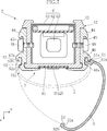
- FIG. 4 is a sectional view taken along line IV-IV in FIG. 3.
- FIG. 4 is a main part sectional view showing a state where a cover of the LED unit shown in FIG. 3 is pushed.
- FIG. 13 is a cross-sectional view taken along line XIII-XIII in FIG. 12. It is sectional drawing which shows the LED unit of the LED lighting apparatus shown in FIG.
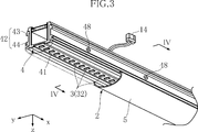
- the LED lighting device A1 of the present embodiment is composed of a mount 1 and an LED unit 2, and is used for, for example, an application to illuminate a floor surface while being attached to an indoor ceiling surface, and has a length of 1227 mm.
- the width is about 120 mm, and the height is about 38 mm.
- the mount 1 includes a main body 11 and a plurality of holders 12.
- the main body 11 has an elongated shape extending in the x direction, and is made of, for example, aluminum.
- the main body 11 is provided with a recess 11a.
- the recess 11a is for accommodating the LED unit 2.
- the main body 11 has a curved surface having a curvature that is continuous with the concave portion 11a interposed therebetween.
- the holder 12 is formed by bending a metal plate, for example, and has a pair of locking pieces 12a and a pair of flexible portions 12b. As shown in FIGS. 9A, 9B, and 9C, the flexible portion 12b is configured to support the locking piece 12a. When an external force is applied to the pair of flexible portions 12b, the pair of locking pieces 12a can be elastically deformed in a direction in which the pair of locking pieces 12a approach and separate from each other.
- the pair of locking pieces 12a are portions that are engaged with the LED unit 2, and are inclined so that the distance from each other decreases toward the upper side in FIG. 9A.
- a plurality of holders 12 are provided in the recess 11a.
- the LED unit 2 includes a plurality of LED modules 3, a support member 4, a cover 5, and a power conversion unit 6.
- the LED unit 2 has a length (about 1220 mm) extending to both ends of the mount 1 in the x direction.
- the LED module 3 includes a pair of leads 31, an LED chip 32, a sealing resin 33, and a reflector 34 as shown in FIG.
- the pair of leads 31 is made of, for example, a Cu alloy, and the LED chip 32 is mounted on one of them.
- a surface of the lead 31 opposite to the surface on which the LED chip 32 is mounted is a mounting terminal 31 a used for surface mounting the LED module 3.
- the LED chip 32 is a light source of the LED module 3, and can emit blue light, for example.
- the sealing resin 33 is for protecting the LED chip 32.
- the sealing resin 33 is formed using a translucent resin containing a fluorescent material that emits yellow light when excited by light from the LED chip 31. Thereby, the LED module 3 can irradiate white. As said fluorescent substance, it may replace with what emits yellow light, and may mix and use what emits red light, and what emits green light.
- the reflector 34 is made of, for example, white resin, and reflects light emitted from the LED chip 32 to the side.
- the support member 4 is for supplying power to the LED modules 3 while supporting the plurality of LED modules 3, and includes a substrate 41 and a bracket 42.
- the substrate 1 has a strip shape in which the x direction is the longitudinal direction and the y direction is the width direction, and is made of, for example, glass epoxy resin.
- 288 LED modules 3 are mounted on the substrate 1.
- the bracket 42 includes a base portion 43 and a pair of outer portions 44.
- Base portion 43 and outer portion 44 are made of, for example, aluminum.
- the base portion 43 has a U-shaped cross section, and the substrate 1 is attached to the outside of the bottom surface.
- the outer portion 44 has a shape that covers the substantially one side portion of the base portion 43 and the edge in the y direction of the substrate 41. As shown in FIGS. 3 and 4, the base portion 43 and the outer portion 44 are fastened by a plurality of bolts 48.
- each outer portion 44 is formed with a locking groove 45.
- the locking groove 45 extends in the x direction and is recessed in the z direction on the opposite side to the emission direction of the LED module 3.
- the locking groove 45 is a portion that engages with the locking piece 12 a of the holder 12.
- a locking groove 46 is formed in one outer portion 44.
- the locking groove 46 extends in the x direction and is recessed in the z direction on the opposite side to the emission direction of the LED module 3.
- the locking groove 46 has a locking surface 46a.
- the locking surface 46a extends in the x direction and faces the opposite side in the emission direction in the z direction.
- a locking groove 47 is formed in the other outer portion 44.
- the locking groove 47 has a locking surface 47a and a convex piece 47b.
- the locking surface 47a extends in the x direction and faces the opposite side in the emission direction in the z direction.
- the convex piece 47b is located closer to the opposite side in the emission direction in the z direction than the locking surface 47a, and is convex in the emission direction.
- the cover 5 has a strip shape with a circular arc cross section extending in the x direction, and is made of, for example, milky white resin that diffuses and transmits light from the LED module 3.
- locking pieces 51 and 52 are formed at both ends of the cover 5.
- the locking piece 51 has an end portion 51a and a stepped portion 51b.
- the end 51a is convex on the opposite side in the emission direction in the z direction.
- the step portion 5b is shaped to shift the end portion 51a inward in the y direction before and after the step portion 5b.
- the locking piece 51 is engaged with the locking groove 46. More specifically, the end portion 51 a is shaped to enter the locking groove 46.
- the step portion 5b is in contact with the locking surface 46a.
- the locking piece 52 has a locking surface 52a and an inclined surface 52b.
- the locking surface 52a faces the emitting direction in the z direction.
- the inclined surface 52b is located closer to the opposite side in the emission direction in the z direction than the locking surface 52a, and faces the convex piece 47b of the support member 4 in the z direction.
- the inclined surface 52b is inclined so as to be located inward in the y direction toward the opposite side in the emission direction in the z direction.
- the locking piece 52 engages with the locking groove 47 of the support member 4. More specifically, the locking surface 52 a is in contact with the locking surface 47 a of the support member 4.
- the power converter 6 fulfills a function of converting commercial AC 100V power into DC 36V, for example, and is accommodated in the support member 4.
- the power conversion unit 6 includes a case 61, a power supply board 62, and a plurality of electronic components 63.
- the case 61 has a U-shaped cross section and is made of metal, for example. As shown in FIG. 6, a plurality of notches 61 a are formed at the end of the case 61.
- the notch 61a is used to fix the power converter 6 by engaging with a portion of the bolt 48 shown in FIG. 4 that protrudes inward from the base 43.
- the power supply board 62 is fixed to the case 2 and a plurality of electronic components 63 are mounted thereon.
- the plurality of electronic components 63 are, for example, a transformer, a rectifier, and a transistor for constant current control.
- a connector 14 extends from the power converter 6 as shown in FIG. The connector 14 is connected to a connector (not shown) attached to the mount 1.
- each LED chip 32 is supplied with DC power having a voltage of about 3 V and a current of about 20 mA.
- the LED lighting device A1 has a comparatively gentle shape that does not protrude significantly from the ceiling surface. This gives a smart impression on what you see without unduly disturbing the indoor aesthetic.
- the LED units 2 of the adjacent LED lighting devices A1 are in a very close positional relationship. For this reason, an excessive non-light emitting region is not formed between the LED illumination devices A1. Therefore, it is possible to give a viewer an impression that it looks good as a lighting device that illuminates a wider indoor floor surface.
- the height of the LED lighting device A1 can be made relatively low.
- the outer portion 44 is configured to hold the substrate 41. Thereby, even if it is a case where it is a case where it is used for a long time in the state where LED lighting apparatus A1 was attached to the ceiling, it can avoid that substrate 41 falls unjustly.
- FIG. 7 shows how the case 5 is attached to the support member 4 when the LED unit 2 is assembled.
- the locking piece 51 of the case 5 is hooked on the locking groove 46 of the support member 4.
- the locking piece 52 is brought close to the locking groove 47.
- the locking surface 47a and the locking surface 52a come into contact with each other.
- the cover 5 can be easily attached.
- FIG. 10 shows how the LED unit 2 is attached to the mount 1 when assembling the LED lighting device A1.
- the LED unit 2 is approached from below, for example, with respect to the mount 1 fixed to the ceiling. Then, the LED unit 2 is pushed between the pair of locking pieces 12 a of the holder 12. Then, the flexible portion 12b is slightly bent, so that the pair of locking pieces 12a are once separated from each other. Thereafter, as shown in FIG. 2, the locking piece 12 a engages with the locking groove 45 of the support member 4. Thus, the LED unit 2 can be easily attached.
- the cover 5 When the LED unit 2 is pushed in, the cover 5 is easily pushed with a strong force. At this time, as shown in FIG. 8, the locking piece 52 moves to the back of the locking groove 47 in the z direction. Then, the inclined surface 52b and the convex piece 47b come into contact with each other. As a result, a force that is directed inward in the y direction is applied to the locking piece 52. Thereby, even if the cover 5 is strongly pressed, the cover 5 can be prevented from being unfairly detached from the support member 4.
- FIG. 11 shows a state where the LED unit 2 is removed from the mount 1.
- a removal jig 8 having a U-shaped cross section is prepared. Then, both side edges of the removal jig 8 are pressed against the locking pieces 12 a of the holder 12. Then, the flexible portion 12b is elastically deformed, and the pair of locking pieces 12a are separated from each other. As a result, the engagement state between the locking piece 12a and the locking groove 45 is released.
- LED lighting apparatus A1 can remove LED unit 2 from mount 1 easily.
- LED lighting device A2 of this embodiment is a type used for illuminating the upper part exposed from the product shelf among the wall surfaces, for example, in a state of being attached to a relatively close corner of the ceiling of the store.
- the LED illumination device A2 has a length of about 1290 mm, a width of about 73 mm, and a height of about 50 mm.
- the main body 11 of the mount 1 has a wedge shape in cross section, and is shaped so that the wall surface side is open when attached to the ceiling.
- the LED unit 2 is accommodated in the mount 1 and is rotatable around the direction x.
- a reflector 44 a is provided on the outer portion 44 of the bracket 42 of the support member 4.
- the reflector 44a is for reflecting light emitted from the LED module 3 in the y direction downward in the z direction.
- Locking grooves 46 and 47 are formed on the edge of the reflector 44a, and the cover 5 is attached.
- the LED unit 2 of the present embodiment has a pair of shafts 7.
- the pair of shafts 7 are attached to both ends of the support member 4 in the x direction.
- the shaft 7 includes a root portion 71 and a tip portion 72.
- the root portion 71 is a portion attached to the support member 4.
- the distal end portion 72 is rotatable with respect to the root portion 71. More specifically, when the distal end portion 72 is rotated, a resistance force is generated to such an extent that it is necessary to use a tool such as pliers.
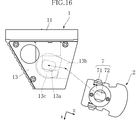
- the mount 1 has a pair of holders 13.
- the pair of holders 13 are attached to both ends of the main body 11 in the x direction.
- the holder 13 is formed with a fitting portion 13a, a flexible portion 13b, and a hook-like portion 13c.
- the fitting portion 13 a is an oval hole and fits with the tip portion 71 of the shaft 7.
- the flexible portion 13b is a portion that holds the fitting portion 13a, and when an external force is applied, the flexible portion 13b is elastically deformed so as to move the fitting portion 13a outward in the x direction.
- the hook-shaped part 13c is located inward in the x direction with respect to the fitting part 13a, and is J-shaped.
- the LED illumination device A2 can rotate the LED unit 2 around the x direction, it can selectively illuminate, for example, a portion of the wall surface above the product shelf.
- the provision of the reflector 44a is suitable for illuminating a desired portion with high illuminance.
- the LED lighting device according to the present invention is not limited to the above-described embodiment.
- the specific configuration of each part of the LED lighting device according to the present invention can be varied in design in various ways.
- the present invention is not limited to the configuration in which the LED module 3 is mounted on the substrate 41, and an insulating layer and a wiring pattern may be formed on the support member 4, and the LED module 3 may be mounted on this.
- the configuration having the LED module 3 is suitable for efficiently emitting the light from the LED chip 32, but the present invention is not limited to this, for example, a configuration in which the LED chip 32 is directly mounted on the substrate 41. Also good.
Landscapes
- Engineering & Computer Science (AREA)
- General Engineering & Computer Science (AREA)
- Microelectronics & Electronic Packaging (AREA)
- Non-Portable Lighting Devices Or Systems Thereof (AREA)
- Fastening Of Light Sources Or Lamp Holders (AREA)
Abstract
Description
上記複数のLEDチップは、その主出射方向が上記第1方向と直角である第2方向に沿っている。
Claims (19)
- 複数のLEDチップと、
上記複数のLEDチップが搭載されたLEDユニットと、
上記LEDユニットを保持するマウントと、
によって構成されることを特徴とする、LED照明装置。 - 上記LEDユニットは、第1方向に延びる細長状であり、
上記複数のLEDチップは、その主出射方向が上記第1方向と直角である第2方向に沿っており、
上記マウントには、上記第2方向に開口し、上記LEDユニットを収容する凹部が形成されている、請求項1に記載のLED照明装置。 - 上記LEDユニットは、上記第1方向と交差する方向に延出し、上記LEDユニットに接続されるコネクタを有し、
上記LEDユニットは、上記マウントの上記第1方向両端におよぶサイズとされている、請求項2に記載のLED照明装置。 - 上記マウントには、上記LEDユニットを保持するための係止片を有するホルダが設けられており、
上記LEDユニットには、上記係止片と係合する固定用係止溝が形成されている、請求項2に記載のLED照明装置。 - 上記ホルダは、上記第1および第2方向のいずれに対しても直角である第3方向において上記LEDユニットを挟む位置に配置されており、かつ上記第2方向において上記複数のLEDチップの出射方向反対側に向かうほど上記第3方向における互いの距離が小となる1対の上記係止片を有しており、かつ
上記LEDユニットには、上記第3方向両側部分に1対の上記固定用係止溝が設けられている、請求項4に記載のLED照明装置。 - 上記ホルダは、互いの上記1対の係止片どうしを上記第3方向において離間させるように弾性変形可能な可撓部を有する、請求項5に記載のLED照明装置。
- 上記LEDユニットは、第1方向に延びる細長状であり、かつ上記マウントに対して上記第1方向周りに回動可能に保持されており、
上記複数のLEDチップは、その主出射方向が上記第1方向と直角である第2方向に沿っている、請求項1に記載のLED照明装置。 - 上記LEDユニットの上記第1方向両端には、それぞれが根元部と、この根元部に対して回動可能とされた先端部とを有する1対のシャフトが設けられており、
上記マウントには、上記先端部に嵌合する嵌合部を有する1対のホルダが設けられている、請求項7に記載のLED照明装置。 - 上記1対のホルダは、互いの上記嵌合部どうしを上記第1方向において離間させるように弾性変形可能な可撓部をそれぞれ有する、請求項8に記載のLED照明装置。
- 上記ホルダには、上記嵌合部よりも上記第1方向内方に位置し、かつ上記シャフトのうち上記嵌合部と嵌合する部分よりも上記根元部よりの部分に係止する鉤状部が形成されている、請求項9に記載のLED照明装置。
- 上記LEDユニットは、上記複数のLEDチップを支持する部分を底部とし、上記第2方向において上記複数のLEDチップの出射方向反対側に開口する断面コの字状の支持部材を有する、請求項2に記載のLED照明装置。
- 上記支持部材は、受けた電力を上記複数のLEDチップに供給するための出力電力に変換する電力変換部を収容している、請求項11に記載のLED照明装置。
- 上記支持部材は、断面コの字状のブラケットと、このブラケットの底部外側に取り付けられ、かつ上記複数のLEDチップが搭載されており、上記第1方向を長手方向とし、上記第1および第2方向のいずれとも直角である第3方向を幅方向とする帯状の基板とからなる、請求項11に記載のLED照明装置。
- 上記ブラケットは、上記基板が取り付けられた断面コの字状のベース部と、上記ベース部の少なくとも一部および上記基板の上記第3方向両端縁を覆い、かつ上記複数のLEDチップを露出させるアウター部とを有する、請求項13に記載のLED照明装置。
- 上記LEDユニットは、上記複数のLEDチップからの光を拡散させつつ透過するカバーをさらに有する、請求項11に記載のLED照明装置。
- 上記カバーは、上記第1方向に延びる帯状であり、かつ上記第1方向および上記第2方向のいずれに対しても直角である第3方向における両側縁には1対の係止片が形成されており、
上記支持部材には、上記1対の係止片と係合する1対のカバー用係止溝が設けられている、請求項15に記載のLED照明装置。 - 上記1対の係止片の一方は、その端部を上記第3方向内方へとシフトさせる段差部を有し、他方は、上記第2方向出射側を向く係止面、およびこの係止面よりも上記第2方向出射方向反対側に位置し、かつ上記第2方向出射方向反対側に向かうほど上記第3方向内方に位置する傾斜面を有し、
上記1対のカバー用係止溝のうち、上記段差部を有する上記係止片と係合するものは、上記第2方向出射方向反対側に凹む凹部を有しており、
上記1対のカバー用係止溝のうち、上記係止面および上記傾斜面を有する上記係止片と係合するものは、上記係止面と当接する係止面、および上記傾斜面に対して上記第2方向出射方向反対側に位置する凸片を有する、請求項16に記載のLED照明装置。 - 上記ベース部と上記アウター部とは、上記第3方向に沿う長軸を有する係止部材によって締結されている、請求項14に記載のLED照明装置。
- 上記マウントは、上記ホルダに上記LEDユニットを保持しない状態から保持する状態を取らせたときに、上記可撓部の変形に伴う上記係止片の移動を許容するためのスペースを有している、請求項6に記載のLED照明装置。
Priority Applications (3)
| Application Number | Priority Date | Filing Date | Title |
|---|---|---|---|
| CN201080008437.XA CN102326021B (zh) | 2009-02-19 | 2010-02-19 | Led照明装置 |
| US13/202,035 US8643043B2 (en) | 2009-02-19 | 2010-02-19 | LED lighting device |
| JP2011500658A JP5702273B2 (ja) | 2009-02-19 | 2010-02-19 | Led照明装置 |
Applications Claiming Priority (2)
| Application Number | Priority Date | Filing Date | Title |
|---|---|---|---|
| JP2009037005 | 2009-02-19 | ||
| JP2009-037005 | 2009-02-19 |
Publications (1)
| Publication Number | Publication Date |
|---|---|
| WO2010095710A1 true WO2010095710A1 (ja) | 2010-08-26 |
Family
ID=42633989
Family Applications (1)
| Application Number | Title | Priority Date | Filing Date |
|---|---|---|---|
| PCT/JP2010/052531 Ceased WO2010095710A1 (ja) | 2009-02-19 | 2010-02-19 | Led照明装置 |
Country Status (4)
| Country | Link |
|---|---|
| US (1) | US8643043B2 (ja) |
| JP (1) | JP5702273B2 (ja) |
| CN (1) | CN102326021B (ja) |
| WO (1) | WO2010095710A1 (ja) |
Cited By (29)
| Publication number | Priority date | Publication date | Assignee | Title |
|---|---|---|---|---|
| JP2011258384A (ja) * | 2010-06-08 | 2011-12-22 | Mitsubishi Electric Corp | 照明器具 |
| JP2012064393A (ja) * | 2010-09-15 | 2012-03-29 | Panasonic Corp | 照明器具および照明器具の組立方法 |
| EP2677235A1 (en) | 2012-06-22 | 2013-12-25 | Hella KGaA Hueck & Co | LED lamp |
| JP2014003034A (ja) * | 2013-09-06 | 2014-01-09 | Mitsubishi Electric Corp | 照明器具 |
| WO2014057661A1 (ja) * | 2012-10-11 | 2014-04-17 | パナソニック株式会社 | 光源ユニット及び照明器具 |
| JP2014078511A (ja) * | 2013-11-15 | 2014-05-01 | Panasonic Corp | 光源ユニット及び照明器具 |
| JP2014132597A (ja) * | 2014-04-18 | 2014-07-17 | Toshiba Lighting & Technology Corp | 照明器具 |
| JP2014207243A (ja) * | 2014-07-02 | 2014-10-30 | 三菱電機株式会社 | 照明器具 |
| JP2015111539A (ja) * | 2013-10-31 | 2015-06-18 | パナソニックIpマネジメント株式会社 | 光源ユニット及び照明器具 |
| WO2015115517A1 (ja) | 2014-01-30 | 2015-08-06 | 興和株式会社 | 照明装置 |
| JP2015162382A (ja) * | 2014-02-27 | 2015-09-07 | 三菱電機株式会社 | 照明器具 |
| JP2015162366A (ja) * | 2014-02-27 | 2015-09-07 | 三菱電機株式会社 | 照明装置 |
| JP2015213088A (ja) * | 2015-07-17 | 2015-11-26 | 三菱電機株式会社 | 照明器具 |
| WO2015190091A1 (ja) * | 2014-06-13 | 2015-12-17 | アイリスオーヤマ株式会社 | 照明装置、照明装置用器具本体及び発光ユニット |
| JP2016122664A (ja) * | 2016-02-26 | 2016-07-07 | 東芝ライテック株式会社 | 照明器具 |
| JP2016136534A (ja) * | 2016-03-25 | 2016-07-28 | 東芝ライテック株式会社 | 照明器具 |
| US9447949B2 (en) | 2014-04-25 | 2016-09-20 | Elite Lighting | Light fixture |
| JP2016174000A (ja) * | 2016-06-02 | 2016-09-29 | 三菱電機株式会社 | 照明器具 |
| JP2016174001A (ja) * | 2016-06-02 | 2016-09-29 | 三菱電機株式会社 | 照明器具 |
| JP2016213173A (ja) * | 2015-10-30 | 2016-12-15 | コイズミ照明株式会社 | 照明器具 |
| JP2016219384A (ja) * | 2015-05-26 | 2016-12-22 | パナソニックIpマネジメント株式会社 | 照明器具 |
| USD790753S1 (en) | 2016-05-17 | 2017-06-27 | Elite Lighting | Body for a light fixture |
| USD797349S1 (en) | 2016-05-17 | 2017-09-12 | Elite Lighting | Ballast room cover for a light fixture |
| JP2017168321A (ja) * | 2016-03-16 | 2017-09-21 | パナソニックIpマネジメント株式会社 | 照明器具 |
| JP2017224633A (ja) * | 2017-09-28 | 2017-12-21 | 三菱電機株式会社 | 照明器具 |
| JP2018037421A (ja) * | 2017-12-06 | 2018-03-08 | 三菱電機株式会社 | 照明器具 |
| JP2019129102A (ja) * | 2018-01-26 | 2019-08-01 | Necライティング株式会社 | 取付具、取付具セット及びそれを用いた照明器具 |
| JP2021048022A (ja) * | 2019-09-17 | 2021-03-25 | パナソニックIpマネジメント株式会社 | 照明器具 |
| JP2023072770A (ja) * | 2021-11-15 | 2023-05-25 | ダイハツ工業株式会社 | 車両用シートの支持脚部カバー体組み付け構造 |
Families Citing this family (43)
| Publication number | Priority date | Publication date | Assignee | Title |
|---|---|---|---|---|
| US8616720B2 (en) | 2010-04-27 | 2013-12-31 | Cooper Technologies Company | Linkable linear light emitting diode system |
| WO2011139768A2 (en) * | 2010-04-28 | 2011-11-10 | Cooper Technologies Company | Linear led light module |
| DE102010041477A1 (de) * | 2010-09-27 | 2012-03-29 | Zumtobel Lighting Gmbh | Anordnung zur Lichtabgabe |
| US9291319B2 (en) | 2012-05-07 | 2016-03-22 | Cooper Technologies Company | Reflectors and reflector orientation feature to prevent non-qualified trim |
| US9062866B1 (en) * | 2012-01-19 | 2015-06-23 | Cooper Technologies Company | Attachment mechanisms for light-emitting diode-based lighting system |
| DE102012206070A1 (de) * | 2012-04-13 | 2013-10-17 | Ridi - Leuchten Gmbh | Lichtband mit Leuchte |
| DE102012206068B4 (de) * | 2012-04-13 | 2016-08-18 | Ridi Leuchten Gmbh | Leuchte mit Lampe |
| JP2014053267A (ja) * | 2012-09-10 | 2014-03-20 | Ricoh Co Ltd | Led直管形ランプ及び照明装置 |
| US9062867B2 (en) * | 2012-12-12 | 2015-06-23 | Cree, Inc. | LED lamp |
| DE202013100307U1 (de) * | 2013-01-23 | 2014-04-29 | Hanning & Kahl Gmbh & Co. Kg | Sicherheitsbeleuchtung für Tunnel |
| US9441814B2 (en) * | 2013-02-08 | 2016-09-13 | Axis Lighting Inc. | Luminaire and output element coupling mechanism therefor |
| US9441933B2 (en) | 2013-02-08 | 2016-09-13 | Axis Lighting Inc. | Method and apparatus for outlining recessed installation of a component within a surface material |
| JP6145923B2 (ja) * | 2013-03-14 | 2017-06-14 | パナソニックIpマネジメント株式会社 | 照明器具 |
| DE102014101403A1 (de) * | 2013-05-15 | 2014-11-20 | Seidel GmbH & Co. KG | Leuchtvorrichtung |
| DE102013216275B4 (de) * | 2013-07-15 | 2015-07-02 | Ridi Leuchten Gmbh | Leuchte |
| US9578724B1 (en) | 2013-08-20 | 2017-02-21 | Ketra, Inc. | Illumination device and method for avoiding flicker |
| USRE48956E1 (en) | 2013-08-20 | 2022-03-01 | Lutron Technology Company Llc | Interference-resistant compensation for illumination devices using multiple series of measurement intervals |
| US9360174B2 (en) * | 2013-12-05 | 2016-06-07 | Ketra, Inc. | Linear LED illumination device with improved color mixing |
| USRE48955E1 (en) | 2013-08-20 | 2022-03-01 | Lutron Technology Company Llc | Interference-resistant compensation for illumination devices having multiple emitter modules |
| DE102014003109B4 (de) * | 2014-03-11 | 2015-10-15 | Nordeon Gmbh | Vorrichtung zum Montieren von Leuchten in einer Decke sowie Einbausystem und Baugruppe damit |
| EP2955429B1 (en) * | 2014-06-03 | 2017-08-30 | OSRAM GmbH | A lighting device |
| US9557214B2 (en) | 2014-06-25 | 2017-01-31 | Ketra, Inc. | Illumination device and method for calibrating an illumination device over changes in temperature, drive current, and time |
| CA2857004C (en) * | 2014-07-16 | 2018-10-02 | Certainteed Canada, Inc. | Ceiling grid system for receiving led strip lights |
| JP6104856B2 (ja) * | 2014-08-07 | 2017-03-29 | Necライティング株式会社 | 照明器具、光源部品および取付部品 |
| US9510416B2 (en) | 2014-08-28 | 2016-11-29 | Ketra, Inc. | LED illumination device and method for accurately controlling the intensity and color point of the illumination device over time |
| US9392660B2 (en) | 2014-08-28 | 2016-07-12 | Ketra, Inc. | LED illumination device and calibration method for accurately characterizing the emission LEDs and photodetector(s) included within the LED illumination device |
| US9453620B2 (en) * | 2014-10-08 | 2016-09-27 | Orion Energy Systems, Inc. | Strip fixture retrofit systems and methods |
| US9574751B1 (en) * | 2015-02-27 | 2017-02-21 | Cooper Technologies Company | Flexible luminaire |
| ITPD20150081A1 (it) * | 2015-04-14 | 2016-10-14 | De Fecondo S R L | Dispositivo di illuminazione orientabile |
| CN205208262U (zh) * | 2015-11-11 | 2016-05-04 | 东莞嘉盛照明科技有限公司 | 轨道条灯 |
| DE202016100613U1 (de) * | 2016-02-08 | 2017-05-09 | Zumtobel Lighting Gmbh | Lichtbandsystem mit länglicher Tragschiene |
| CN105570743B (zh) * | 2016-02-23 | 2018-06-29 | 深圳市格丽照明有限公司 | Led线形灯的灯条模块化安装结构 |
| DE102016117157B3 (de) * | 2016-09-13 | 2018-02-01 | Insta Gmbh | Leuchtenanordnung |
| US10458607B2 (en) * | 2017-09-01 | 2019-10-29 | Motor City Washworks, Inc. | Lighting device for a component of a vehicle wash system |
| DE102017009152A1 (de) * | 2017-09-29 | 2019-04-04 | Led-Linear Gmbh | LED-Leuchte |
| CN108258098B (zh) * | 2017-12-26 | 2020-02-07 | 深圳市尚可饰科技有限公司 | 一种无机集成深紫外led封装结构 |
| CN208398007U (zh) * | 2018-06-20 | 2019-01-18 | 广东欧曼科技股份有限公司 | 一种灯带固定夹 |
| US11272599B1 (en) | 2018-06-22 | 2022-03-08 | Lutron Technology Company Llc | Calibration procedure for a light-emitting diode light source |
| US10823367B1 (en) * | 2019-04-26 | 2020-11-03 | Insight Lighting, Inc. | Modular LED light fixture with spaced diffuser |
| US11073262B2 (en) | 2019-05-20 | 2021-07-27 | Signify Holding B.V. | Luminaire with a releasably lockable wire cover |
| DE102023132212B3 (de) | 2023-11-20 | 2025-01-16 | Rzb Rudolf Zimmermann, Bamberg Gmbh | Mehrteiliger Gehäusekörper |
| GB2636776A (en) * | 2023-12-21 | 2025-07-02 | Jcc Lighting Products Ltd | An improved lighting assembly |
| ES1320891Y (es) * | 2024-10-17 | 2025-09-29 | Antares Iluminacion S A U | Dispositivo lumínico de emisión de luz ambiental |
Citations (3)
| Publication number | Priority date | Publication date | Assignee | Title |
|---|---|---|---|---|
| JP2002093204A (ja) * | 2000-09-14 | 2002-03-29 | Mitsuzo Tanihata | 棒状ランプ及びその製造方法 |
| JP2003303504A (ja) * | 2002-04-10 | 2003-10-24 | Meiji Natl Ind Co Ltd | 発光ダイオードを用いた照明器具 |
| JP2008120210A (ja) * | 2006-11-10 | 2008-05-29 | Inoac Corp | 照明器具 |
Family Cites Families (15)
| Publication number | Priority date | Publication date | Assignee | Title |
|---|---|---|---|---|
| JPS55141416U (ja) * | 1979-03-30 | 1980-10-09 | ||
| JPH0643930Y2 (ja) * | 1989-03-15 | 1994-11-14 | 松下電工株式会社 | 照明カバー取付構造 |
| US5541823A (en) * | 1995-02-16 | 1996-07-30 | Fallon Luminous Products Corp. | Housing assembly for illuminated glass tubing |
| JP3260593B2 (ja) * | 1995-06-09 | 2002-02-25 | 株式会社小糸製作所 | 自動車用信号灯 |
| JP3662153B2 (ja) * | 1999-11-30 | 2005-06-22 | シャープ株式会社 | シート搬送回転体の着脱装置及びシート搬送装置 |
| JP2003179818A (ja) * | 2001-12-10 | 2003-06-27 | Shinko Electric Ind Co Ltd | バックプレート、ハウジング及び撮像装置 |
| JP4197984B2 (ja) * | 2003-04-28 | 2008-12-17 | ニッポ電機株式会社 | ランプソケット |
| CN2903657Y (zh) * | 2005-11-25 | 2007-05-23 | 华兴电子工业股份有限公司 | 发光二极管的灯管结构 |
| JP3118932U (ja) * | 2005-11-30 | 2006-02-09 | アイホウ電器株式会社 | 照明装置 |
| JP3126166U (ja) * | 2006-06-13 | 2006-10-19 | 三和サインワークス株式会社 | 看板の光源ユニットと内照式看板 |
| JP4519148B2 (ja) * | 2007-02-13 | 2010-08-04 | 昭和電工株式会社 | 照明装置 |
| JP5030661B2 (ja) * | 2007-05-16 | 2012-09-19 | シャープ株式会社 | 照明装置 |
| CN201093222Y (zh) * | 2007-09-29 | 2008-07-30 | 华兴电子工业股份有限公司 | 发光二极管照明灯具 |
| CN101498860B (zh) * | 2008-02-01 | 2012-05-16 | 群康科技(深圳)有限公司 | 直下式背光模组和液晶显示装置 |
| CN201173419Y (zh) * | 2008-04-11 | 2008-12-31 | 徐培实 | 便携式太阳能爆闪灯 |
-
2010
- 2010-02-19 WO PCT/JP2010/052531 patent/WO2010095710A1/ja not_active Ceased
- 2010-02-19 CN CN201080008437.XA patent/CN102326021B/zh active Active
- 2010-02-19 JP JP2011500658A patent/JP5702273B2/ja active Active
- 2010-02-19 US US13/202,035 patent/US8643043B2/en not_active Expired - Fee Related
Patent Citations (3)
| Publication number | Priority date | Publication date | Assignee | Title |
|---|---|---|---|---|
| JP2002093204A (ja) * | 2000-09-14 | 2002-03-29 | Mitsuzo Tanihata | 棒状ランプ及びその製造方法 |
| JP2003303504A (ja) * | 2002-04-10 | 2003-10-24 | Meiji Natl Ind Co Ltd | 発光ダイオードを用いた照明器具 |
| JP2008120210A (ja) * | 2006-11-10 | 2008-05-29 | Inoac Corp | 照明器具 |
Cited By (35)
| Publication number | Priority date | Publication date | Assignee | Title |
|---|---|---|---|---|
| JP2011258384A (ja) * | 2010-06-08 | 2011-12-22 | Mitsubishi Electric Corp | 照明器具 |
| JP2012064393A (ja) * | 2010-09-15 | 2012-03-29 | Panasonic Corp | 照明器具および照明器具の組立方法 |
| EP2677235A1 (en) | 2012-06-22 | 2013-12-25 | Hella KGaA Hueck & Co | LED lamp |
| WO2013189768A1 (en) | 2012-06-22 | 2013-12-27 | Hella Kgaa Hueck & Co. | Led lamp |
| WO2014057661A1 (ja) * | 2012-10-11 | 2014-04-17 | パナソニック株式会社 | 光源ユニット及び照明器具 |
| JP2014078422A (ja) * | 2012-10-11 | 2014-05-01 | Panasonic Corp | 照明器具 |
| JP2014003034A (ja) * | 2013-09-06 | 2014-01-09 | Mitsubishi Electric Corp | 照明器具 |
| JP2015111539A (ja) * | 2013-10-31 | 2015-06-18 | パナソニックIpマネジメント株式会社 | 光源ユニット及び照明器具 |
| JP2014078511A (ja) * | 2013-11-15 | 2014-05-01 | Panasonic Corp | 光源ユニット及び照明器具 |
| JPWO2015115517A1 (ja) * | 2014-01-30 | 2017-03-23 | 興和株式会社 | 照明装置 |
| JP2019125581A (ja) * | 2014-01-30 | 2019-07-25 | 興和株式会社 | 照明装置 |
| WO2015115517A1 (ja) | 2014-01-30 | 2015-08-06 | 興和株式会社 | 照明装置 |
| JP2015162382A (ja) * | 2014-02-27 | 2015-09-07 | 三菱電機株式会社 | 照明器具 |
| JP2015162366A (ja) * | 2014-02-27 | 2015-09-07 | 三菱電機株式会社 | 照明装置 |
| JP2014132597A (ja) * | 2014-04-18 | 2014-07-17 | Toshiba Lighting & Technology Corp | 照明器具 |
| US9447949B2 (en) | 2014-04-25 | 2016-09-20 | Elite Lighting | Light fixture |
| JPWO2015190091A1 (ja) * | 2014-06-13 | 2017-04-20 | アイリスオーヤマ株式会社 | 照明装置、照明装置用器具本体及び発光ユニット |
| WO2015190091A1 (ja) * | 2014-06-13 | 2015-12-17 | アイリスオーヤマ株式会社 | 照明装置、照明装置用器具本体及び発光ユニット |
| JP2014207243A (ja) * | 2014-07-02 | 2014-10-30 | 三菱電機株式会社 | 照明器具 |
| JP2016219384A (ja) * | 2015-05-26 | 2016-12-22 | パナソニックIpマネジメント株式会社 | 照明器具 |
| JP2015213088A (ja) * | 2015-07-17 | 2015-11-26 | 三菱電機株式会社 | 照明器具 |
| JP2016213173A (ja) * | 2015-10-30 | 2016-12-15 | コイズミ照明株式会社 | 照明器具 |
| JP2016122664A (ja) * | 2016-02-26 | 2016-07-07 | 東芝ライテック株式会社 | 照明器具 |
| JP2017168321A (ja) * | 2016-03-16 | 2017-09-21 | パナソニックIpマネジメント株式会社 | 照明器具 |
| JP2016136534A (ja) * | 2016-03-25 | 2016-07-28 | 東芝ライテック株式会社 | 照明器具 |
| USD790753S1 (en) | 2016-05-17 | 2017-06-27 | Elite Lighting | Body for a light fixture |
| USD797349S1 (en) | 2016-05-17 | 2017-09-12 | Elite Lighting | Ballast room cover for a light fixture |
| JP2016174001A (ja) * | 2016-06-02 | 2016-09-29 | 三菱電機株式会社 | 照明器具 |
| JP2016174000A (ja) * | 2016-06-02 | 2016-09-29 | 三菱電機株式会社 | 照明器具 |
| JP2017224633A (ja) * | 2017-09-28 | 2017-12-21 | 三菱電機株式会社 | 照明器具 |
| JP2018037421A (ja) * | 2017-12-06 | 2018-03-08 | 三菱電機株式会社 | 照明器具 |
| JP2019129102A (ja) * | 2018-01-26 | 2019-08-01 | Necライティング株式会社 | 取付具、取付具セット及びそれを用いた照明器具 |
| JP2021048022A (ja) * | 2019-09-17 | 2021-03-25 | パナソニックIpマネジメント株式会社 | 照明器具 |
| JP7437668B2 (ja) | 2019-09-17 | 2024-02-26 | パナソニックIpマネジメント株式会社 | 照明器具 |
| JP2023072770A (ja) * | 2021-11-15 | 2023-05-25 | ダイハツ工業株式会社 | 車両用シートの支持脚部カバー体組み付け構造 |
Also Published As
| Publication number | Publication date |
|---|---|
| JP5702273B2 (ja) | 2015-04-15 |
| US8643043B2 (en) | 2014-02-04 |
| JPWO2010095710A1 (ja) | 2012-08-30 |
| CN102326021B (zh) | 2014-04-23 |
| US20110297971A1 (en) | 2011-12-08 |
| CN102326021A (zh) | 2012-01-18 |
Similar Documents
| Publication | Publication Date | Title |
|---|---|---|
| JP5702273B2 (ja) | Led照明装置 | |
| JP7601436B2 (ja) | Led照明装置 | |
| JP5281382B2 (ja) | Ledランプ | |
| JP2009117328A (ja) | 照明装置 | |
| JP2012204162A (ja) | 照明装置および照明器具 | |
| JP2010123359A (ja) | Ledランプ | |
| JP5605549B2 (ja) | 照明器具 | |
| KR20090010850U (ko) | Led를 광원으로 하는 조명장치 | |
| JP2010171236A (ja) | Ledランプ | |
| JP3163443U (ja) | Led式照明装置 | |
| JP5301248B2 (ja) | Ledランプ | |
| JP6297299B2 (ja) | 照明器具 | |
| JP2022186893A (ja) | Led照明器具 | |
| JP3163304U (ja) | Led照明装置 | |
| CN206918799U (zh) | 照明器具 | |
| CN102404913A (zh) | 照明器具 | |
| KR101061218B1 (ko) | Led조명장치용 방열판 | |
| JP7131865B2 (ja) | 取付具、取付具セット及びそれを用いた照明器具 | |
| JP2011210513A (ja) | ミニクリプトンランプ型led電球 | |
| JP3193001U (ja) | Led照明器具 | |
| JP5896125B2 (ja) | 発光装置及び照明装置 | |
| JP2012146439A (ja) | 照明器具 | |
| JP5037646B2 (ja) | 発光ダイオード照明灯 | |
| KR102073567B1 (ko) | Fpl등기구 호환형 led 조명기구 | |
| JP7308571B2 (ja) | 取付具、取付具セット及びそれを用いた照明器具 |
Legal Events
| Date | Code | Title | Description |
|---|---|---|---|
| WWE | Wipo information: entry into national phase |
Ref document number: 201080008437.X Country of ref document: CN |
|
| 121 | Ep: the epo has been informed by wipo that ep was designated in this application |
Ref document number: 10743835 Country of ref document: EP Kind code of ref document: A1 |
|
| WWE | Wipo information: entry into national phase |
Ref document number: 13202035 Country of ref document: US Ref document number: 2011500658 Country of ref document: JP |
|
| NENP | Non-entry into the national phase |
Ref country code: DE |
|
| 122 | Ep: pct application non-entry in european phase |
Ref document number: 10743835 Country of ref document: EP Kind code of ref document: A1 |