WO2010092971A1 - パイロクロア型酸化物の調製方法、固体高分子形燃料電池、燃料電池システムおよび燃料電池用電極触媒の製造方法 - Google Patents
パイロクロア型酸化物の調製方法、固体高分子形燃料電池、燃料電池システムおよび燃料電池用電極触媒の製造方法 Download PDFInfo
- Publication number
- WO2010092971A1 WO2010092971A1 PCT/JP2010/051934 JP2010051934W WO2010092971A1 WO 2010092971 A1 WO2010092971 A1 WO 2010092971A1 JP 2010051934 W JP2010051934 W JP 2010051934W WO 2010092971 A1 WO2010092971 A1 WO 2010092971A1
- Authority
- WO
- WIPO (PCT)
- Prior art keywords
- fuel cell
- aqueous solution
- pyrochlore
- oxide
- catalyst
- Prior art date
- Legal status (The legal status is an assumption and is not a legal conclusion. Google has not performed a legal analysis and makes no representation as to the accuracy of the status listed.)
- Ceased
Links
Images

Classifications
-
- H—ELECTRICITY
- H01—ELECTRIC ELEMENTS
- H01M—PROCESSES OR MEANS, e.g. BATTERIES, FOR THE DIRECT CONVERSION OF CHEMICAL ENERGY INTO ELECTRICAL ENERGY
- H01M4/00—Electrodes
- H01M4/86—Inert electrodes with catalytic activity, e.g. for fuel cells
- H01M4/90—Selection of catalytic material
- H01M4/9016—Oxides, hydroxides or oxygenated metallic salts
-
- C—CHEMISTRY; METALLURGY
- C01—INORGANIC CHEMISTRY
- C01G—COMPOUNDS CONTAINING METALS NOT COVERED BY SUBCLASSES C01D OR C01F
- C01G37/00—Compounds of chromium
-
- C—CHEMISTRY; METALLURGY
- C01—INORGANIC CHEMISTRY
- C01G—COMPOUNDS CONTAINING METALS NOT COVERED BY SUBCLASSES C01D OR C01F
- C01G39/00—Compounds of molybdenum
-
- C—CHEMISTRY; METALLURGY
- C01—INORGANIC CHEMISTRY
- C01G—COMPOUNDS CONTAINING METALS NOT COVERED BY SUBCLASSES C01D OR C01F
- C01G41/00—Compounds of tungsten
-
- C—CHEMISTRY; METALLURGY
- C01—INORGANIC CHEMISTRY
- C01G—COMPOUNDS CONTAINING METALS NOT COVERED BY SUBCLASSES C01D OR C01F
- C01G45/00—Compounds of manganese
-
- C—CHEMISTRY; METALLURGY
- C01—INORGANIC CHEMISTRY
- C01G—COMPOUNDS CONTAINING METALS NOT COVERED BY SUBCLASSES C01D OR C01F
- C01G55/00—Compounds of ruthenium, rhodium, palladium, osmium, iridium, or platinum
-
- H—ELECTRICITY
- H01—ELECTRIC ELEMENTS
- H01M—PROCESSES OR MEANS, e.g. BATTERIES, FOR THE DIRECT CONVERSION OF CHEMICAL ENERGY INTO ELECTRICAL ENERGY
- H01M4/00—Electrodes
- H01M4/86—Inert electrodes with catalytic activity, e.g. for fuel cells
- H01M4/90—Selection of catalytic material
- H01M4/9075—Catalytic material supported on carriers, e.g. powder carriers
- H01M4/9083—Catalytic material supported on carriers, e.g. powder carriers on carbon or graphite
-
- C—CHEMISTRY; METALLURGY
- C01—INORGANIC CHEMISTRY
- C01P—INDEXING SCHEME RELATING TO STRUCTURAL AND PHYSICAL ASPECTS OF SOLID INORGANIC COMPOUNDS
- C01P2002/00—Crystal-structural characteristics
- C01P2002/30—Three-dimensional structures
- C01P2002/36—Three-dimensional structures pyrochlore-type (A2B2O7)
-
- C—CHEMISTRY; METALLURGY
- C01—INORGANIC CHEMISTRY
- C01P—INDEXING SCHEME RELATING TO STRUCTURAL AND PHYSICAL ASPECTS OF SOLID INORGANIC COMPOUNDS
- C01P2002/00—Crystal-structural characteristics
- C01P2002/50—Solid solutions
- C01P2002/52—Solid solutions containing elements as dopants
-
- C—CHEMISTRY; METALLURGY
- C01—INORGANIC CHEMISTRY
- C01P—INDEXING SCHEME RELATING TO STRUCTURAL AND PHYSICAL ASPECTS OF SOLID INORGANIC COMPOUNDS
- C01P2006/00—Physical properties of inorganic compounds
- C01P2006/40—Electric properties
-
- H—ELECTRICITY
- H01—ELECTRIC ELEMENTS
- H01M—PROCESSES OR MEANS, e.g. BATTERIES, FOR THE DIRECT CONVERSION OF CHEMICAL ENERGY INTO ELECTRICAL ENERGY
- H01M8/00—Fuel cells; Manufacture thereof
- H01M8/10—Fuel cells with solid electrolytes
- H01M2008/1095—Fuel cells with polymeric electrolytes
-
- Y—GENERAL TAGGING OF NEW TECHNOLOGICAL DEVELOPMENTS; GENERAL TAGGING OF CROSS-SECTIONAL TECHNOLOGIES SPANNING OVER SEVERAL SECTIONS OF THE IPC; TECHNICAL SUBJECTS COVERED BY FORMER USPC CROSS-REFERENCE ART COLLECTIONS [XRACs] AND DIGESTS
- Y02—TECHNOLOGIES OR APPLICATIONS FOR MITIGATION OR ADAPTATION AGAINST CLIMATE CHANGE
- Y02E—REDUCTION OF GREENHOUSE GAS [GHG] EMISSIONS, RELATED TO ENERGY GENERATION, TRANSMISSION OR DISTRIBUTION
- Y02E60/00—Enabling technologies; Technologies with a potential or indirect contribution to GHG emissions mitigation
- Y02E60/30—Hydrogen technology
- Y02E60/50—Fuel cells
Definitions
- the present invention relates to a platinum alternative electrode catalyst for a fuel cell, and also relates to a pyrochlore type oxide that can be used as the catalyst.
- the present invention also relates to a polymer electrolyte fuel cell and a fuel cell system.
- a fuel cell is a device that generates electricity by electrochemically reacting hydrogen (fuel) with oxygen. Since the product of this reaction is water in principle, there is little impact on the environment, and fuel cells are expected to be used for household cogeneration systems and are being developed.
- Pt or a Pt alloy is used as a catalyst component used as an electrode catalyst of a polymer electrolyte fuel cell (Patent Document 1).
- the surface of the Pt catalyst may be poisoned by CO in the reformed gas obtained by reforming a hydrocarbon-based fuel such as city gas. Poisoning impairs catalyst activity and increases anode overvoltage. As a result, there is a decrease in power generation efficiency, and there is a need for the development of catalyst components that reduce this poisoning by CO.
- Non-Patent Document 1 It is known that a pyrochlore type oxide catalyst exhibits high performance as a cathode for a fuel cell.
- Non-Patent Documents 2 and 3 By the way, the fuel cell electrode catalyst is required to have a large specific surface area of the catalyst in order to exhibit high performance for both the cathode and the anode. In general, a method of increasing the specific surface area of the catalyst is often employed by using carbon black or the like having a large specific surface area and good electronic conductivity as the carrier.
- the conventional pyrochlore oxide catalyst requires a long time heating at a temperature close to 100 ° C. and a firing step at a temperature close to 300 ° C. at the time of catalyst preparation.
- the accompanying reduction in specific surface area was inevitable.
- An object of the present invention is to provide a method for preparing a pyrochlore type oxide having a larger specific surface area.
- Another object of the present invention is to provide a polymer electrolyte fuel cell that has improved power generation efficiency and can be manufactured at a lower cost.
- Still another object of the present invention is to provide a fuel cell system that has improved power generation efficiency and can be manufactured at a lower cost.
- An object of the present invention is to provide a method for producing an electrode catalyst for a fuel cell that has a larger specific surface area, is relatively inexpensive, and has high electrode activity per mass.
- the following method for preparing a pyrochlore oxide, a polymer electrolyte fuel cell, a fuel cell system, and a method for producing a fuel cell electrode catalyst are provided.
- a 2 B 2 O 7-Z (However, A and B each represent a metal element, Z represents a number from 0 to 1, A includes A 1 which is at least one selected from the group consisting of Pb, Sn and Zn, B contains Ru, W, Mo, Ir, Rh, Mn, and B 1 is at least one selected from the group consisting of Cr and Re. )
- the A includes a metal A 2 different from the A 1 and / or the B includes a metal B 2 different from the B 1 ,
- a 2 and B 2 are each independently La, Ce, Pr, Nd, Pm, Sm, Eu, Gd, Dy, Ho, Er, Tm, Yb, Lu, Y, Sc, Pb, Bi, Mo, Os, Ru, Is at least one selected from the group consisting of W, Ze, Re, Cr, Fe, Mn, Ir, Pt, Pd, Rh, Co and Ni.
- the method according to any one of 1) to 4).
- the A (NO 3 ) 2 contains at least Pb (NO 3 ) 2 or Sn (NO 3 ) 2 ,
- the K 2 BO 4 is K 2 RuO 4 and the Na 2 BO 4 is Na 2 RuO 4 .
- the A (NO 3 ) 2 contains at least Pb (NO 3 ) 2 or Sn (NO 3 ) 2 ,
- the K 2 BO 4 is K 2 WO 4 and the Na 2 BO 4 is Na 2 WO 4 .
- the A (NO 3 ) 2 contains at least Pb (NO 3 ) 2 or Sn (NO 3 ) 2 ,
- the K 2 BO 4 is K 2 MoO 4 and the Na 2 BO 4 is Na 2 MoO 4 .
- a fuel cell system including the polymer electrolyte fuel cell according to 10) above.
- a fuel cell system including the polymer electrolyte fuel cell according to 11) above.
- a method for producing a fuel cell electrode catalyst comprising a pyrochlore type oxide represented by: A method for producing an electrode catalyst for a fuel cell, comprising a step of generating a pyrochlore oxide by a reaction between the halide or nitrate of A and the alkali metal acid of B.
- a conductive material is dispersed in advance in one of the first aqueous solution and the second aqueous solution, and then the dropping is performed. Forming the pyrochlore-type oxide on a conductive material; 15) The method described.
- a method for preparing a pyrochlore oxide having a larger specific surface area is provided.
- a polymer electrolyte fuel cell having improved power generation efficiency and capable of being manufactured at a lower cost is provided.
- a fuel cell system with improved power generation efficiency and capable of being manufactured at a lower cost is provided.
- a method for producing a fuel cell electrode catalyst having a larger specific surface area, a relatively low cost, and a high electrode activity per mass is provided.
- FIG. 1 is a schematic diagram of a fuel cell system according to an embodiment.
- the pyrochlore type oxide catalyst can be produced in the liquid phase at about room temperature.
- the temperature condition of the solution reaction at such a relatively low temperature, grain growth during generation can be suppressed as compared with a conventional synthesis method in which treatment is performed at a high temperature.
- the method of the present invention since high temperature treatment such as calcination is unnecessary, it is difficult to prepare a conventional pyrochlore type oxide catalyst.
- the specific surface area of the pyrochlore oxide catalyst is increased by dispersing the conductive material and supporting the pyrochlore oxide on the conductive material (on the surface of the conductive material). Grain growth can be suppressed.
- a battery electrode catalyst can be produced.
- a decrease in specific surface area is suppressed, and a highly useful pyrochlore type oxide catalyst having high activity as a cathode catalyst for a fuel cell or a CO-resistant anode catalyst is obtained. can get.
- the halide or nitrate of A is sometimes referred to as A precursor, and the alkali metal acid of B is sometimes referred to as B precursor.
- a 2 B 2 O 7-Z a pyrochlore type oxide represented by A 2 B 2 O 7-Z , wherein A is at least one selected from Pb, Sn and Zn (referred to as A 1 ), and B is Ru, W, Mo , producing Ir, Rh, Mn, what is at least one selected from Cr and Re (referred B 1).
- aqueous solution (first aqueous solution) of the metal A halide or nitrate an aqueous solution (second aqueous solution) of the metal B alkali metal acid is dropped.
- the metal A halide or nitrate aqueous solution (first aqueous solution) is dropped into the metal B alkali metal acid aqueous solution (second aqueous solution).
- the amount of the aqueous solution to be dropped between the first aqueous solution and the second aqueous solution can be the stoichiometric amount of the amount of the other aqueous solution.
- the stoichiometric amount here means the stoichiometric ratio of metals A and B contained in the composition of the pyrochlore type oxide obtained as the final product, and does not necessarily coincide with the neutralization point of the acid / base reaction. .
- the reaction temperature in the preparation of pyrochlore oxide is preferably about room temperature.
- the substantially room temperature specifically means 0 ° C. or more and 60 ° C. or less, preferably 10 ° C. or more and 50 ° C. or less.
- the use temperature of the aqueous metal salt solution is preferably 0 ° C. or higher, more preferably 10 ° C. or higher from the viewpoint of preventing precursor precipitation, and 60 from the viewpoint of preventing precipitation aggregation. ° C or less is preferable, and 50 ° C or less is more preferable.
- the concentration of the metal salt aqueous solution (the concentration of the halide or nitrate of metal A in the first aqueous solution and the concentration of the acid alkali metal salt in the second aqueous solution) is preferably 5 to 500 mmol / L, more preferably It is in the range of 10 to 300 mmol / L.
- concentration of the aqueous solution is 5 mmol / L or more, it is possible to easily prevent the yield from being reduced and not efficient with respect to the reaction scale.
- it when it is 500 mmol / L or less, it can easily prevent the aqueous solution itself from becoming unstable from the viewpoint of precipitation, etc., and easily prevent aggregation from being accelerated due to local reaction during precipitation. Can do.
- pyrochlore oxide precipitate
- the obtained pyrochlore type oxide is usually a black or brown solid.
- the obtained pyrochlore type oxide can be further washed with pure water to remove impurities such as residual ions.
- the temperature at this time may be substantially room temperature.
- the composition has a composition in which part of the B site is substituted (also referred to as dope) with another metal. This dope may improve the catalytic activity, and this form is effective for this purpose.
- the A includes a metal (referred to as A 2 ) different from the A 1 and / or the B includes a metal (referred to as B 2 ) different from the B 1 (hereinafter sometimes referred to as A 2). and B 2 of doped metal).
- the metals A 2 and B 2 are each independently La, Ce, Pr, Nd, Pm, Sm, Eu, Gd, Dy, Ho, Er, Tm, Yb, Lu, Y, Sc, Pb, Bi, Mo. Os, Ru, W, Ze, Re, Cr, Fe, Mn, Ir, Pt, Pd, Rh, Co, and Ni are preferable. These metals may be used alone or in combination of two or more.
- These doping metals may be in the preparation of the pyrochlore type oxide, previously dissolved in an aqueous solution of a halide or nitrate of the metal A 1 is a raw material if the metal A 2.
- the metal B 2 in an aqueous solution of the metal alkali of the metal B 1 as a raw material, can be previously dissolved. Both A 2 and B 2 can be dissolved in each aqueous solution in the form of a salt.
- the metal A 2 salt one that can be stably dissolved in an aqueous solution in which the metal salt of A 1 is dissolved can be used.
- a salt that can be stably dissolved in an aqueous solution in which the metal salt of B 1 is dissolved can be used.
- a salt of A 2 it is possible to use a halide or nitrate of A 2, as the salt of B 2 can be a metal alkali of B 2.
- the chemical formula is A 1 2-X A 2 X B 1 2-Y B 2 Y O 7-Z (where 0 ⁇ X ⁇ 1, 0 ⁇ Y ⁇ 1, 0 ⁇ Z ⁇ 1) can be adjusted.
- the pyrochlore oxide can be synthesized at about room temperature in the liquid phase.
- the pyrochlore oxide preferably has a BET specific surface area of 80 m 2 / g or more. According to the present invention, a pyrochlore oxide having such a specific surface area can be obtained.
- the pyrochlore type oxide produced by the present invention is useful as a catalyst for promoting the electrode reaction.
- a solid conductive material such as carbon in a pyrochlore type oxide and using it as such an electrode catalyst, an electronic conductivity suitable for an electrode reaction is ensured, and a reaction gas such as a fuel gas or an oxidant gas is obtained. It is possible to secure a hole for suitably diffusing. Therefore, the oxygen reduction activity of the obtained electrode catalyst can be further improved.
- the pyrochlore oxide and the solid conductive material may be used by being physically mixed with a mixer such as a mortar or a ball mill.
- a mixer such as a mortar or a ball mill.
- the pyrochlore oxide is supported on the conductive material. It is done.
- a solid conductive material as a carrier, the dispersibility of the pyrochlore oxide can be increased, and a highly active catalyst having a larger catalyst specific surface area and higher stability can be obtained.
- the solid conductive material a solid that is insoluble in water, which is a solvent used during synthesis, in particular, solid particles can be used.
- the solid conductive material is preferably a porous body having an appropriate particle size and specific surface area.
- a material mainly composed of carbon is preferably used, but the material is not particularly limited as long as it can support the pyrochlore oxide in a desired dispersion state.
- the material has a certain degree of proton conductivity or can hold a medium that conducts protons.
- a porous carbon carrier such as carbon black is preferably used.
- the conductive material that contains carbon include acetylene black, ketjen black, vulcan, black pearl, graphitized acetylene black, graphitized vulcan, graphitized ketjen black, and graphitized.
- One or a mixture of two or more selected from the group consisting of black pearl, carbon nanotube, carbon nanofiber, carbon nanohorn, carbon fibril and the like is preferably used.
- the BET specific surface area of the conductive material is preferably 80 m 2 / g or more from the viewpoint of supporting the pyrochlore type oxide in a highly dispersed state.
- the specific surface area is 80 m 2 / g or more, dispersibility of the catalyst component in the conductive material is suitable, and suitable power generation performance is obtained.
- the size of the conductive material is not particularly limited, but from the viewpoint of controlling the ease of loading and the catalyst utilization rate within an appropriate range, the average diameter is 5 to 200 nm, preferably about 10 to 100 nm. It is good to do.
- the average diameter of the conductive material is measured and calculated by TEM observation.
- the content of the pyrochlore type oxide is preferably 5 to 90% by mass with respect to the total amount of the pyrochlore type oxide and the conductive material.
- the content is 90% by mass or less, it is easy to improve the degree of dispersion of the catalyst component on the conductive material, and the effect of improving the power generation performance by increasing the supported amount can be suitably obtained.
- the supported amount is 5% by mass or more, the catalytic activity per unit mass is suitable, and it is possible to easily prevent a large amount of electrode catalyst from being required to obtain a desired catalytic activity.
- These conductive materials are used in the preparation of pyrochlore oxides in the metal A halide or nitrate aqueous solution (first aqueous solution) or the metal B alkali metal acid aqueous solution (first aqueous solution). 2 aqueous solution).
- the pyrochlore oxide obtained by the present invention is mixed with an electrode catalyst conventionally used in a polymer electrolyte fuel cell, for example, an electrode catalyst in which noble metal particles and / or noble metal alloy particles are supported on a conductive material. Thus, it can be used as an electrode catalyst for fuel cells.
- Such an electrode catalyst containing a noble metal and a pyrochlore type oxide is obtained by using an electrode catalyst in which noble metal particles and / or noble metal alloy particles are supported on a conductive material as a raw material when preparing a pyrochlore type oxide. Disperse in advance in an aqueous solution of metal A halide or nitrate (first aqueous solution) or in an aqueous solution of the metal acid alkali metal B (second aqueous solution), and then drop as described above. Can be manufactured.
- an electrode catalyst in which noble metal particles and / or noble metal alloy particles are supported on a conductive material which is used in the production of an electrode catalyst containing a noble metal and a pyrochlore type oxide, it has been generally used for an electrode catalyst in a fuel cell. Any of those used (for example, Pt / C, PtCo / C, Pt—Ru / C, etc., where C represents carbon) can be used without particular limitation.
- the pyrochlore type oxide produced according to the present invention has been described above by taking the electrode catalyst in the polymer electrolyte fuel cell as an example, but is not limited thereto, and the alkaline fuel cell, the phosphoric acid fuel cell, It can be used as an electrode catalyst in various fuel cells such as acid-type electrolyte fuel cells, direct methanol fuel cells, and micro fuel cells. Moreover, it is not limited to the electrode catalyst for fuel cells, It can use suitably for another use.
- a basic cell 50 of a polymer electrolyte fuel cell which is a type of fuel cell using the pyrochlore oxide catalyst, includes a membrane-electrode assembly (MEA) 40, gas seal materials 3, 9 , And separators 2 and 10.
- MEA Membrane Electrode Assembly
- the MEA is a GDL (Gas Diffusion Layer) via an electrode catalyst layer 5 (anode catalyst layer) supplied with hydrogen fuel on one surface of a solid polymer electrolyte membrane 6 having hydrogen ion conductivity.
- 4 and GDL 8 is laminated on the other surface of the electrolyte membrane 6 via an electrode catalyst layer 7 (cathode catalyst layer) to which oxygen is supplied.
- the electrode catalyst layer is a porous layer formed by a mixture of a catalyst component that promotes an electrode reaction, a conductive component, and a solid polymer electrolyte having ion conductivity.
- the gas sealing material 3 is disposed around the GDL 4 and the electrode catalyst layer 5 in order to seal gas and liquid.
- the gas sealing material 9 is disposed around the GDL 8 and the electrode catalyst layer 7 in order to seal gas and liquid.
- the basic cell 50 is configured by sandwiching the MEA 40 between a pair of separators 2 and 10.
- a power generation cell is configured by arranging current collector plates 1 and 11 made of a highly conductive material at both ends of the basic cell and fastening them with bolts and nuts, respectively.
- the pyrochlore oxide prepared according to the present invention is used as at least one component of the electrode catalyst in the anode and / or cathode catalyst layers 5 and / or 7 in the power generation cell.
- the pair of separators 2 and 10 partition an anode gas (for example, hydrogen) that is a fuel (reducing agent) and a cathode gas (for example, oxygen) that is an oxidizing agent.
- anode gas for example, hydrogen
- a cathode gas for example, oxygen
- a flow path for introducing an anode gas into the anode is formed on the surface on the GDL side.
- the separator 10 is formed with a channel for introducing a cathode gas into the cathode on the surface on the GDL side.
- the anode catalyst layer 5 (fuel electrode) on the side where the flow path of the anode gas such as hydrogen gas is formed is provided with a catalyst layer for promoting fuel oxidation. It is done. In this catalyst layer, a hydrogen oxidation reaction that oxidizes the hydrogen-containing gas of the fuel and converts it into hydrogen ions occurs.
- the cathode catalyst layer 7 (oxygen electrode) on the side where the flow path of the cathode gas such as air (oxygen gas) is formed is provided with a catalyst layer for promoting the reduction of the oxidant.
- oxygen contained in the oxidant gas is reduced, that is, combined with hydrogen ions that have passed through the solid polymer electrolyte membrane to cause a reduction reaction of oxygen that becomes water. Electric energy is obtained directly from the reaction energy obtained by this chemical reaction to generate electricity.
- the anode and cathode electrode catalyst layers are supported by a GDL having a conductive and gas diffusing function, respectively.
- a GDL having a conductive and gas diffusing function
- Examples of GDL4 and 8 materials include carbon cloth.
- Water repellent treatment may be performed between the GDLs 4 and 8 and the electrode catalyst layers 5 and 7 in order to improve gas diffusibility.
- a fuel cell body (fuel cell stack) is configured by stacking a large number of basic cells 50 and sandwiching them by applying a pressing force in the stacking direction.
- a plurality of manifolds for supplying and discharging hydrogen gas (cathode gas), oxygen gas (anode gas) and cooling medium are formed through the side portion of the fuel cell stack, and are formed in each manifold and separator.
- the anode gas channel and the cathode gas channel are configured to communicate with each other.
- a flow path of a cooling medium water, ethylene glycol, etc.
- gaskets and the like arranged around each peripheral portion and the manifold through-holes are used to prevent leakage of the gas and refrigerant to the outside. Sealing is performed by sealing members (gas sealing materials 3 and 9 and a cooling medium sealing member). As these sealing members, materials that can withstand use in the operating temperature range are appropriately used.
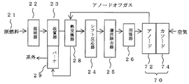
- FIG. 2 is a schematic diagram of the fuel cell system according to the embodiment.
- the fuel cell system mainly includes a hydrogen production apparatus (FPS) that produces hydrogen from raw fuel such as kerosene, liquefied petroleum gas (LPG), and city gas, and a fuel cell stack.
- FPS hydrogen production apparatus
- the FPS mainly includes a desulfurizer 22, a reformer 23, and a shift reactor 24.
- a desulfurizer 22 As the raw fuel 21, kerosene, LPG, city gas or the like can be used.
- kerosene is supplied to the desulfurizer 22 as the raw fuel 21, desulfurized, and then reformed by the reformer 23.
- the reformed gas obtained from the reformer 23 is cooled by the anode off gas of the fuel cell stack 70 in the heat exchanger 28 and then supplied to the shift reactor 24.
- the reformed gas having the CO concentration reduced by the shift reactor 24 is further humidified by the humidifier 26 after the CO concentration is further reduced by the CO selective removal device 25.
- the reformed gas that has passed through the humidifier 26 is supplied to each anode 72 of the fuel cell stack 70.
- a pyrochlore type oxide or the like is used as the anode catalyst of the fuel cell stack 70, power can be generated even when the CO concentration is higher than when a normal platinum catalyst is used for the anode. Therefore, even if the CO concentration in the gas discharged from the CO selective remover temporarily increases when the air inflow amount to the CO selective remover fluctuates, the operation is possible, that is, the reliability of the fuel cell system. It can contribute to improvement.
- the anode off-gas discharged from the anode 72 is heated by heat exchange with the reformed gas in the heat exchanger 28, supplied as a combustion fuel to a burner 29 provided in the reformer, burned here, and then outside the system. Exhausted. Air is supplied as an oxidant to the cathode 74 of the fuel cell stack 70. Cathode off-gas (not shown) discharged from the cathode 74 is exhausted outside the system after heat is recovered as necessary.
- Example 1-1 Preparation of pyrochlore type oxide Pb 2 Ru 2 O 7-Z 0.5 mol / L of lead nitrate (II) in which lead (II) nitrate (Pb (NO 3 ) 2 ) was dissolved in pure water )
- the aqueous solution was put into a beaker, and while stirring at room temperature (about 25 ° C.), a 0.5 mol / L potassium ruthenate aqueous solution in which potassium ruthenate (K 2 RuO 4 ) was dissolved in pure water was mixed with Pb.
- the mixture was added dropwise so that the molar ratio of Ru was 1: 1.
- the precipitate produced in the beaker was filtered off and washed with pure water, and the produced pyrochlore oxide was taken out and dried at room temperature.
- the BET specific surface area of this product was 69 m 2 / g.
- Example 1-2 Preparation of pyrochlore type oxide Sn 2 Ru 2 O 7-Z 0.5 mol / L tin nitrate (II) in which tin (II) nitrate (Sn (NO 3 ) 2 ) was dissolved in pure water )
- the aqueous solution was put into a beaker, and while stirring at room temperature (about 25 ° C.), a 0.5 mol / L potassium ruthenate aqueous solution in which potassium ruthenate (K 2 RuO 4 ) was dissolved in pure water was added with Sn.
- the mixture was added dropwise so that the molar ratio of Ru was 1: 1. Thereafter, the precipitate produced in the beaker was filtered off and washed with pure water, and the produced pyrochlore oxide was taken out and dried at room temperature.
- Example 1-3 Preparation of Pyrochlore Type Oxide Pb 2 Ru 2 O 7-Z 0.5 mol / L of lead nitrate (II) in which lead (II) nitrate (Pb (NO 3 ) 2 ) was dissolved in pure water )
- the aqueous solution was put into a beaker, and while stirring at room temperature (about 25 ° C.), a 0.5 mol / L aqueous sodium ruthenate solution in which sodium ruthenate (Na 2 RuO 4 ) was dissolved in pure water
- the mixture was added dropwise so that the molar ratio of Ru was 1: 1. Thereafter, the precipitate produced in the beaker was filtered off and washed with pure water, and the produced catalyst was taken out and dried at room temperature.
- Example 1-4 Preparation of Pyrochlore Oxide Sn 2 Ru 2 O 7-Z 0.5 mol / L tin nitrate (II) in which tin (II) nitrate (Sn (NO 3 ) 2 ) was dissolved in pure water )
- the aqueous solution was put into a beaker, and while stirring at room temperature (about 25 ° C.), a 0.5 mol / L sodium ruthenate aqueous solution in which sodium ruthenate (Na 2 RuO 4 ) was dissolved in pure water was added to Sn and The mixture was added dropwise so that the molar ratio of Ru was 1: 1. Thereafter, the precipitate produced in the beaker was filtered off and washed with pure water, and the produced catalyst was taken out and dried at room temperature.
- Example 1-5 Preparation of Pyrochlore Oxide Pb 2 W 2 O 7-Z 0.5 mol / L of lead nitrate (II) prepared by dissolving lead (II) nitrate (Pb (NO 3 ) 2 ) in pure water ) Aqueous solution was put into a beaker and stirred at room temperature (about 25 ° C.), a 0.5 mol / L potassium tungstate aqueous solution in which potassium tungstate (K 2 WO 4 ) was dissolved in pure water was mixed with Pb. The dropwise addition was performed so that the molar ratio of W was 1: 1. Thereafter, the precipitate produced in the beaker was filtered off and washed with pure water, and the produced catalyst was taken out and dried at room temperature.
- lead nitrate (II) prepared by dissolving lead (II) nitrate (Pb (NO 3 ) 2 ) in pure water
- Aqueous solution was put into a beaker and stirred at room temperature
- Example 1-6 Preparation of pyrochlore type oxide Sn 2 W 2 O 7-Z 0.5 mol / L tin nitrate (II) in which tin (II) nitrate (Sn (NO 3 ) 2 ) was dissolved in pure water )
- Aqueous solution was put into a beaker and stirred at room temperature (about 25 ° C.), a 0.5 mol / L sodium tungstate aqueous solution in which sodium tungstate (Na 2 WO 4 ) was dissolved in pure water was added with Sn.
- the dropwise addition was performed so that the molar ratio of W was 1: 1.
- the precipitate produced in the beaker was filtered off and washed with pure water, and the produced catalyst was taken out and dried at room temperature.
- Example 1--7 Preparation of pyrochlore type oxide Pb 2 Mo 2 O 7-Z 0.5 mol / L of lead nitrate (II) in which lead (II) nitrate (Pb (NO 3 ) 2 ) was dissolved in pure water )
- a 0.5 mol / L potassium molybdate aqueous solution in which potassium molybdate (K 2 MoO 4 ) was dissolved in pure water was mixed with Pb.
- the dropwise addition was performed so that the molar ratio of W was 1: 1.
- the precipitate produced in the beaker was filtered off and washed with pure water, and the produced catalyst was taken out and dried at room temperature.
- Example 2-1 Preparation of carbon-supported pyrochlore type oxide Pb 2 Ru 2 O 7-Z / C Lead (II) nitrate (Pb (NO 3 ) 2 ) dissolved in pure water at 0.5 mol / L
- a lead (II) nitrate aqueous solution was put into a beaker, and the carbon powder was dispersed while stirring at room temperature (about 25 ° C.).
- As the carbon powder ketjen black obtained from Tanaka Kikinzoku Kogyo Co., Ltd. and having a specific surface area of 800 m 2 / g was used.
- a 0.5 mol / L potassium ruthenate aqueous solution in which potassium ruthenate (K 2 RuO 4 ) was dissolved in pure water was dropped.
- Example 3 Production of Power Generation Cell Using Pyrochlore Type Oxide as Cathode
- the power generation cell according to this example uses the pyrochlore type oxide according to Example 1-1 as a cathode catalyst.
- the power generation cell according to this example will be described with reference to FIG.
- a method for producing a cathode catalyst layer using a pyrochlore type oxide will be described.
- 1 g of acetylene black powder and 1 g of pyrochlore type oxide produced in the same manner as in Example 1-1 were dispersed in isopropanol, and a dispersion of perfluorocarbon sulfonic acid powder dispersed in ethyl alcohol was mixed.
- a cathode catalyst paste was prepared.
- a water-repellent treated carbon paper having a thickness of 300 ⁇ m was cut into A4 size for GDL8.
- the cathode catalyst paste described above was applied to one surface of the water-repellent treated carbon paper using a bar coater, thereby creating a cathode catalyst layer using a pyrochlore oxide on one surface of the carbon paper.
- the amount of paste catalyst applied by the bar coater is 1 ⁇ mol / cm 2 for the pyrochlore oxide and 1 mg / cm 2 for the perfluorocarbon sulfonic acid contained in the electrode catalyst layer 7 after application. It is adjusted to.
- a pair of reaction electrodes (GDL and electrode) are formed so that the electrode catalyst layer 5 is in contact with one surface of the electrolyte membrane 6 having an outer dimension of 8 cm ⁇ 8 cm and the electrode catalyst layer 7 is in contact with the other surface of the electrolyte membrane 6.
- the MEA 40 is manufactured by joining the catalyst layer and the catalyst layer) by hot pressing.
- reaction electrode manufactured as described above was used on the cathode side.
- a catalyst layer adjusted so that the amount of Pt in Pt—Ru / C was 0.4 mg / cm 2 and the amount of perfluorocarbon sulfonic acid was 1 mg / cm 2 was used.
- the same GDL4 as GDL8 was used.
- a perfluorosulfonic acid electrolyte membrane (made by DuPont, trade name: Nafion CS-212) having a thickness of 50 ⁇ m was used as the electrolyte membrane 6.
- the MEA 40 was sandwiched between a pair of separators 2 and 10 to form a basic cell 50.
- Current collector plates 1 and 11 made of gold-plated copper were disposed at both ends of the basic cell 50, respectively, and tightened with bolts, nuts, and the like, and a power generation cell according to this example was configured.
- Example 4 Preparation of power generation cell using pyrochlore type oxide as anode
- the power generation cell according to this example uses the pyrochlore type oxide catalyst according to Example 1-1 as an anode catalyst.
- the power generation cell according to this example will be described with reference to FIG.
- anode catalyst layer using a pyrochlore type oxide For the electrode catalyst, 1 g of acetylene black powder and 1 g of pyrochlore type oxide produced in the same manner as in Example 1-1 were dispersed in isopropanol, and perfluorocarbon sulfonic acid powder was dispersed in ethyl alcohol. John solution was mixed to prepare an anode catalyst paste.
- a water-repellent treated carbon paper having a thickness of 300 ⁇ m was cut into A4 size for GDL4.
- anode catalyst layer using a pyrochlore oxide is formed on one surface of the carbon paper. .
- the electrode catalyst layer 5 (anode catalyst layer) is embedded in the carbon paper.
- the amount of paste catalyst applied by the bar coater is 1 ⁇ mol / cm 2 for the pyrochlore oxide and 1 mg / cm 2 for the perfluorocarbon sulfonic acid contained in the electrode catalyst layer 7 after application. It is adjusted to.
- a pair of reaction electrodes (GDL and electrode) are formed so that the electrode catalyst layer 5 is in contact with one surface of the electrolyte membrane 6 having an outer dimension of 8 cm ⁇ 8 cm and the electrode catalyst layer 7 is in contact with the other surface of the electrolyte membrane 6.
- the MEA 40 is manufactured by joining the catalyst layer and the catalyst layer) by hot pressing.
- reaction electrode manufactured as described above was used on the anode side.
- a catalyst layer adjusted so that the amount of Pt in Pt / C was 0.4 mg / cm 2 and the amount of perfluorocarbon sulfonic acid was 1 mg / cm 2 was used.
- the same GDL8 as GDL4 was used.
- the MEA 40 was sandwiched between a pair of separators 2 and 10 to form a basic cell 50.
- Current collector plates 1 and 11 made of gold-plated copper were disposed at both ends of the basic cell 50, respectively, and tightened with bolts, nuts, and the like, and a power generation cell according to this example was configured.
- Example 5 Fuel cell system using pyrochlore type oxide as cathode
- the fuel cell system according to this example includes a plurality of basic cells according to Example 3. The fuel cell system according to this example will be described with reference to FIG.
- Kerosene was used as the raw fuel 21.
- the CO that could not be removed by the reactor 24 and the shift reactor was sequentially passed through a CO selective remover 25 that oxidizes using air and a humidifier 26 heated to 70 ° C.
- the reformed gas thus obtained was supplied to the anode 72 of the fuel cell stack 70.
- the voltage at 200 mA / cm 2 was 0.5V.
- Example 6 Fuel Cell System Using Pyrochlore Type Oxide for Anode
- the fuel cell system according to this example uses a pyrochlore type oxide for the anode, compared to the fuel cell system according to Example 5,
- the power generation voltage fluctuation when the CO concentration at the CO selective oxidation catalyst outlet fluctuates can be suppressed better.
- Kerosene was used as the raw fuel 21.
- the CO that could not be removed by the reactor 24 and the shift reactor was sequentially passed through a CO selective remover 25 that oxidizes using air and a humidifier 26 heated to 70 ° C.
- the reformed gas thus obtained was supplied to the anode 72 of the fuel cell stack 70.
- the inventors have found a method capable of preparing a pyrochlore type oxide at room temperature.
- a pyrochlore type oxide having a large specific surface area can be obtained.
- the choice of the carrier could be expanded by using carbon as the carrier.
- the pyrochlore type oxide produced according to the present invention as an electrode catalyst on the anode side, it is possible to reduce a decrease in reliability due to CO concentration fluctuation at the CO selective removal device outlet of the fuel cell system.
Landscapes
- Chemical & Material Sciences (AREA)
- Organic Chemistry (AREA)
- Inorganic Chemistry (AREA)
- Engineering & Computer Science (AREA)
- Materials Engineering (AREA)
- Chemical Kinetics & Catalysis (AREA)
- Electrochemistry (AREA)
- General Chemical & Material Sciences (AREA)
- Fuel Cell (AREA)
- Catalysts (AREA)
- Inert Electrodes (AREA)
- Inorganic Compounds Of Heavy Metals (AREA)
Priority Applications (1)
| Application Number | Priority Date | Filing Date | Title |
|---|---|---|---|
| US13/148,188 US8329129B2 (en) | 2009-02-10 | 2010-02-10 | Method for preparing pyrochlore oxide, polymer electrolyte fuel cell, fuel cell system, and method for producing electro catalyst for fuel cell |
Applications Claiming Priority (2)
| Application Number | Priority Date | Filing Date | Title |
|---|---|---|---|
| JP2009-028876 | 2009-02-10 | ||
| JP2009028876A JP5684971B2 (ja) | 2009-02-10 | 2009-02-10 | パイロクロア型酸化物の調製方法、固体高分子形燃料電池、燃料電池システムおよび燃料電池用電極触媒の製造方法 |
Publications (1)
| Publication Number | Publication Date |
|---|---|
| WO2010092971A1 true WO2010092971A1 (ja) | 2010-08-19 |
Family
ID=42561813
Family Applications (1)
| Application Number | Title | Priority Date | Filing Date |
|---|---|---|---|
| PCT/JP2010/051934 Ceased WO2010092971A1 (ja) | 2009-02-10 | 2010-02-10 | パイロクロア型酸化物の調製方法、固体高分子形燃料電池、燃料電池システムおよび燃料電池用電極触媒の製造方法 |
Country Status (3)
| Country | Link |
|---|---|
| US (1) | US8329129B2 (enExample) |
| JP (1) | JP5684971B2 (enExample) |
| WO (1) | WO2010092971A1 (enExample) |
Cited By (1)
| Publication number | Priority date | Publication date | Assignee | Title |
|---|---|---|---|---|
| CN113871608A (zh) * | 2021-09-24 | 2021-12-31 | 常州大学 | 一种高熵焦绿石氧化物电池负极材料及其制备和应用方法 |
Families Citing this family (11)
| Publication number | Priority date | Publication date | Assignee | Title |
|---|---|---|---|---|
| JP5684971B2 (ja) | 2009-02-10 | 2015-03-18 | Jx日鉱日石エネルギー株式会社 | パイロクロア型酸化物の調製方法、固体高分子形燃料電池、燃料電池システムおよび燃料電池用電極触媒の製造方法 |
| JP5503465B2 (ja) * | 2010-08-30 | 2014-05-28 | Jx日鉱日石エネルギー株式会社 | パイロクロア型酸化物触媒の調製方法および燃料電池用電極触媒の製造方法 |
| GB201021352D0 (en) * | 2010-12-16 | 2011-01-26 | Johnson Matthey Plc | Catalyst layer |
| JP5841812B2 (ja) * | 2011-11-16 | 2016-01-13 | 株式会社日本触媒 | 複合体の製造方法及びそれにより製造される複合体 |
| WO2013125238A1 (ja) * | 2012-02-23 | 2013-08-29 | Jx日鉱日石エネルギー株式会社 | 電気化学還元装置および、芳香族炭化水素化合物または含窒素複素環式芳香族化合物の水素化体の製造方法 |
| MX379464B (es) | 2013-03-14 | 2025-03-11 | Shepherd Color Co | Pigmento de pirocloro simultáneamente sustituido y estructuras relacionadas. |
| US9126189B2 (en) | 2013-07-11 | 2015-09-08 | Sabic Global Technologies B.V. | Method of making pyrochlores |
| CN104525182B (zh) * | 2014-12-26 | 2018-11-30 | 南京大学 | 多孔纳米结构的铈铌锑基复合颗粒光催化剂、制备及应用 |
| JP6745733B2 (ja) * | 2017-01-30 | 2020-08-26 | 国立大学法人北見工業大学 | 酸素発生反応触媒、酸素発生反応電極及び酸素発生反応方法 |
| KR102219538B1 (ko) * | 2019-03-25 | 2021-02-24 | 재단법인대구경북과학기술원 | 내구성 및 성능 향상을 위한 고분자 전해질막 연료전지용 막 전극 접합체 |
| JP6799346B1 (ja) * | 2020-05-21 | 2020-12-16 | 学校法人同志社 | 酸素触媒、当該酸素触媒を用いた電極及び電気化学測定法 |
Citations (5)
| Publication number | Priority date | Publication date | Assignee | Title |
|---|---|---|---|---|
| JPS5472500A (en) * | 1977-10-31 | 1979-06-09 | Philips Nv | Preparation of resistance material and resistor arranged by this material |
| JPH01257136A (ja) * | 1988-04-07 | 1989-10-13 | Sumitomo Metal Mining Co Ltd | 導電材用ルテニウム酸鉛微粉末、これを含む厚膜抵抗体ペースト、前記ルテニウム酸鉛微粉末の製造方法 |
| JPH02302327A (ja) * | 1989-05-16 | 1990-12-14 | Sumitomo Metal Mining Co Ltd | ルテニウム酸鉛微粉末の製造方法 |
| JPH08119637A (ja) * | 1994-10-27 | 1996-05-14 | Shoei Chem Ind Co | ルテニウム酸鉛微粉末の製造方法 |
| JP2003217598A (ja) * | 2002-01-18 | 2003-07-31 | Kyushu Electric Power Co Inc | 燃料電池電極材料 |
Family Cites Families (5)
| Publication number | Priority date | Publication date | Assignee | Title |
|---|---|---|---|---|
| US3801490A (en) | 1972-07-18 | 1974-04-02 | Ppg Industries Inc | Pyrochlore electrodes |
| US4129525A (en) | 1977-12-02 | 1978-12-12 | Exxon Research & Engineering Co. | Method of making lead-rich and bismuth-rich pyrochlore compounds using an alkaline medium |
| JPH0536418A (ja) | 1991-03-13 | 1993-02-12 | Fuji Electric Co Ltd | 固体高分子電解質型燃料電池およびその製造方法 |
| JPH08315635A (ja) * | 1995-05-17 | 1996-11-29 | Sumitomo Metal Mining Co Ltd | 厚膜用抵抗ペーストの製造方法 |
| JP5684971B2 (ja) | 2009-02-10 | 2015-03-18 | Jx日鉱日石エネルギー株式会社 | パイロクロア型酸化物の調製方法、固体高分子形燃料電池、燃料電池システムおよび燃料電池用電極触媒の製造方法 |
-
2009
- 2009-02-10 JP JP2009028876A patent/JP5684971B2/ja not_active Expired - Fee Related
-
2010
- 2010-02-10 WO PCT/JP2010/051934 patent/WO2010092971A1/ja not_active Ceased
- 2010-02-10 US US13/148,188 patent/US8329129B2/en not_active Expired - Fee Related
Patent Citations (5)
| Publication number | Priority date | Publication date | Assignee | Title |
|---|---|---|---|---|
| JPS5472500A (en) * | 1977-10-31 | 1979-06-09 | Philips Nv | Preparation of resistance material and resistor arranged by this material |
| JPH01257136A (ja) * | 1988-04-07 | 1989-10-13 | Sumitomo Metal Mining Co Ltd | 導電材用ルテニウム酸鉛微粉末、これを含む厚膜抵抗体ペースト、前記ルテニウム酸鉛微粉末の製造方法 |
| JPH02302327A (ja) * | 1989-05-16 | 1990-12-14 | Sumitomo Metal Mining Co Ltd | ルテニウム酸鉛微粉末の製造方法 |
| JPH08119637A (ja) * | 1994-10-27 | 1996-05-14 | Shoei Chem Ind Co | ルテニウム酸鉛微粉末の製造方法 |
| JP2003217598A (ja) * | 2002-01-18 | 2003-07-31 | Kyushu Electric Power Co Inc | 燃料電池電極材料 |
Non-Patent Citations (2)
| Title |
|---|
| T.OZAKI ET AL.: "Bi-functional Electrocatalytic Properties of Pb-Ru-Based Pyrochlore-Type Oxide", ITE LETTERS ON BATTERIES, NEW TECHNOLOGIES & MEDICINE, vol. 6, no. 4, 30 August 2005 (2005-08-30), pages 335 - 338 * |
| Y.SHIMIZU ET AL.: "Electrocatalytic Properties of Pyrochlore-type Oxides in Acidic Electrolyte", ITE LETTERS ON BATTERIES, NEW TECHNOLOGIES & MEDICINE, vol. 4, no. 5, 2003, pages 582 - 586 * |
Cited By (1)
| Publication number | Priority date | Publication date | Assignee | Title |
|---|---|---|---|---|
| CN113871608A (zh) * | 2021-09-24 | 2021-12-31 | 常州大学 | 一种高熵焦绿石氧化物电池负极材料及其制备和应用方法 |
Also Published As
| Publication number | Publication date |
|---|---|
| JP5684971B2 (ja) | 2015-03-18 |
| US8329129B2 (en) | 2012-12-11 |
| JP2010184824A (ja) | 2010-08-26 |
| US20110294652A1 (en) | 2011-12-01 |
Similar Documents
| Publication | Publication Date | Title |
|---|---|---|
| JP5684971B2 (ja) | パイロクロア型酸化物の調製方法、固体高分子形燃料電池、燃料電池システムおよび燃料電池用電極触媒の製造方法 | |
| CN102593472B (zh) | 催化剂、制法、燃料电池、电极及锂空气电池 | |
| KR100552697B1 (ko) | 금속 산화물-탄소 복합체로 이루어진 촉매 담체 및 이를이용한연료전지 | |
| EP2270907B1 (en) | Catalyst for fuel cell, fuel cell system and associated methods | |
| CN100595953C (zh) | 载体催化剂及制法、含其的电极和含该电极的燃料电池 | |
| JP5022335B2 (ja) | 燃料電池用電極触媒とその製造方法、及び該電極触媒を含む電極を具備した燃料電池 | |
| US20120156582A1 (en) | Fuel cell | |
| KR101494432B1 (ko) | 연료전지용 전극 촉매, 그 제조방법 및 이를 이용한 연료전지 | |
| CN103227333A (zh) | 复合物、含其的催化剂、含其的燃料电池和锂空气电池 | |
| EP3312921B1 (en) | Cell, fuel cell stack, fuel cell system and membrane-electrode joined body | |
| JP5385897B2 (ja) | 膜電極接合体、燃料電池および燃料電池システム | |
| JP2022527452A (ja) | 一酸化炭素耐性アノードを備える水素ポンピングセルを有しシフト反応器を統合した固体酸化物形燃料電池システム | |
| CN102468507A (zh) | 通过膜中的氧化物担载的贵金属改进了燃料电池耐久性 | |
| JP2000012043A (ja) | 固体高分子電解質型燃料電池用電極触媒、並びに該触媒を用いた電極、電解質膜―電極接合体および固体高分子電解質型燃料電池 | |
| WO2006057139A1 (ja) | 固体高分子型燃料電池 | |
| CN111313031B (zh) | 复合催化剂颗粒及其制备方法和应用 | |
| US20140342262A1 (en) | Fuel Cell | |
| TW201140926A (en) | Ink, catalyst layer for fuel cell produced using the ink, and use of the catalyst layer | |
| US20050238936A1 (en) | Membrane-electrode assembly for fuel cell and fuel cell system comprising the same | |
| JP2003187851A (ja) | 固体高分子型燃料電池、その燃料極触媒および固体高分子型燃料電池を用いた発電方法 | |
| JP2009158131A (ja) | 電極触媒及び電極触媒の製造方法 | |
| JP5298303B2 (ja) | 膜電極接合体および燃料電池 | |
| KR101310781B1 (ko) | 알칼리 전해질형 전지용 촉매 복합체, 이의 제조 방법, 이를 포함하는 연료 전지용 막-전극 어셈블리, 및 이를 포함하는 연료 전지 | |
| US7960073B2 (en) | Membrane electrode assembly for fuel cell and fuel cell system including the same | |
| JP5470131B2 (ja) | 家庭用定置式燃料電池システム |
Legal Events
| Date | Code | Title | Description |
|---|---|---|---|
| 121 | Ep: the epo has been informed by wipo that ep was designated in this application |
Ref document number: 10741248 Country of ref document: EP Kind code of ref document: A1 |
|
| WWE | Wipo information: entry into national phase |
Ref document number: 13148188 Country of ref document: US |
|
| NENP | Non-entry into the national phase |
Ref country code: DE |
|
| 122 | Ep: pct application non-entry in european phase |
Ref document number: 10741248 Country of ref document: EP Kind code of ref document: A1 |