WO2010092747A1 - 電子線装置および電子線装置用試料保持装置 - Google Patents
電子線装置および電子線装置用試料保持装置 Download PDFInfo
- Publication number
- WO2010092747A1 WO2010092747A1 PCT/JP2010/000282 JP2010000282W WO2010092747A1 WO 2010092747 A1 WO2010092747 A1 WO 2010092747A1 JP 2010000282 W JP2010000282 W JP 2010000282W WO 2010092747 A1 WO2010092747 A1 WO 2010092747A1
- Authority
- WO
- WIPO (PCT)
- Prior art keywords
- sample
- electron beam
- beam apparatus
- gas
- diaphragm
- Prior art date
- Legal status (The legal status is an assumption and is not a legal conclusion. Google has not performed a legal analysis and makes no representation as to the accuracy of the status listed.)
- Ceased
Links
Images


Classifications
-
- H—ELECTRICITY
- H01—ELECTRIC ELEMENTS
- H01J—ELECTRIC DISCHARGE TUBES OR DISCHARGE LAMPS
- H01J37/00—Discharge tubes with provision for introducing objects or material to be exposed to the discharge, e.g. for the purpose of examination or processing thereof
- H01J37/02—Details
- H01J37/20—Means for supporting or positioning the object or the material; Means for adjusting diaphragms or lenses associated with the support
-
- H—ELECTRICITY
- H01—ELECTRIC ELEMENTS
- H01J—ELECTRIC DISCHARGE TUBES OR DISCHARGE LAMPS
- H01J2237/00—Discharge tubes exposing object to beam, e.g. for analysis treatment, etching, imaging
- H01J2237/006—Details of gas supplies, e.g. in an ion source, to a beam line, to a specimen or to a workpiece
-
- H—ELECTRICITY
- H01—ELECTRIC ELEMENTS
- H01J—ELECTRIC DISCHARGE TUBES OR DISCHARGE LAMPS
- H01J2237/00—Discharge tubes exposing object to beam, e.g. for analysis treatment, etching, imaging
- H01J2237/20—Positioning, supporting, modifying or maintaining the physical state of objects being observed or treated
- H01J2237/2002—Controlling environment of sample
- H01J2237/2003—Environmental cells
- H01J2237/2004—Biological samples
Definitions
- the present invention relates to an electron beam apparatus for observing a sample using an electron beam and a sample holder for an electron beam apparatus, and in particular, a micro gas space (environmental cell) of an atmospheric gas containing a sample with a diaphragm inside a sample chamber.
- Electron beam equipment and sample holder for electron beam equipment that can accurately control the pressure in the environmental cell and perform high-resolution observation and high-sensitivity analysis immediately after the reaction in a high-pressure gas atmosphere Relates to the device.
- Patent Document 1 and Patent Document 2 For observation in a gas atmosphere, as described in Patent Document 1 and Patent Document 2, there is a method in which a sample holder is provided with a mechanism for sandwiching a sample between two grids and introducing and exhausting gas between them. Further, as described in Patent Document 3, there is a method of providing a cylindrical cover around a sample and providing a hole with a diaphragm through which two electron beams pass through the cover.
- Patent Document 5 there is a method of observing a gas reaction at a high temperature by providing a capillary tube for blowing a gas so as to oppose a heater for heating a sample.
- a charged particle beam device has a mechanism for heating a sample and a mechanism for quenching by blowing gas to a reaction site, There is a method in which the reaction process is observed, and then the observation site is cut out with a focused ion beam and observed with a transmission electron microscope.
- An object of the present invention is to provide an electron beam apparatus and a sample holding apparatus for an electron beam apparatus capable of observing a reaction between a sample and a gas with high resolution while maintaining a gas atmosphere even with a thin diaphragm.
- the sample holding means includes a gas A gas supply means for supplying gas, and an exhaust means for exhausting, in order to constitute a cell in which the gas atmosphere and the vacuum in the sample chamber are isolated, and the atmosphere around the sample is sealed, a diaphragm is arranged above and below the sample, and A mechanism for injecting gas to the outside of the diaphragm was provided inside the sample chamber.
- a gas having a low electron beam scattering ability for example, hydrogen, oxygen, nitrogen or the like was used.
- the material of the diaphragm was an amorphous film composed of light elements such as a carbon film, an oxide film, and a nitride film that can transmit an electron beam.
- a micro gas space (environmental cell) of an atmospheric gas containing a sample with a diaphragm is created inside the sample chamber using an electron beam apparatus, and the sample and gas are kept in a state where the gas atmosphere is maintained even with a thin diaphragm.
- the reaction can be observed with high resolution.
- the basic block diagram of the electron beam apparatus 1 which is one Example of this invention, and the sample holder 6 for electron beam apparatuses.
- maintenance apparatus 6 for electron beam apparatuses of one Example. 1 is a configuration diagram of an electron beam apparatus sample holding device 6 according to an embodiment, (a) an electron beam apparatus sample holding apparatus cross-sectional view, (b) an electron beam apparatus sample holding apparatus tip cross-sectional view, and (c) an electron beam apparatus. Top view of the sample holding device tip.
- Operation explanatory diagram of the electron beam apparatus sample holding device 6 of one embodiment (a) the electron beam apparatus sample holding apparatus 6 cross-sectional view, (b) the electron beam apparatus sample holding apparatus 6 tip cross-sectional view, (c) The top view of the front end of the sample holder 6 for an electron beam apparatus.
- Explanatory drawing of operation movement of the sample holder 6 for electron beam apparatuses of one Example. 1 is a cross-sectional view of a sample holding device for an electron beam apparatus and a top view thereof.
- the sample holder 6 for electron beam apparatuses of one Example (a) Sectional drawing of the sample holder for electron beam apparatuses, (b) Top view of the sample holder for electron beam apparatuses.
- the sample holder 6 for electron beam apparatuses of one Example (a) Sectional drawing of the sample holder for electron beam apparatuses, (b) Top view of the sample holder for electron beam apparatuses.
- the sample holder 6 for electron beam apparatuses of one Example (a) Sectional drawing of the sample holder for electron beam apparatuses, (b) Top view of the sample holder for electron beam apparatuses. Explanatory drawing of the sample holder 6 for electron beam apparatuses of one Example.
- the sample holder 6 for electron beam apparatuses of one Example (a) Sectional drawing of the sample holder for electron beam apparatuses, (b) Top view of the sample holder for electron beam apparatuses.
- the sample holder 6 for electron beam apparatuses of one Example (a) Sectional drawing of the sample holder for electron beam apparatuses, (b) Top view of the sample holder for electron beam apparatuses.
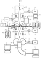
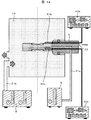
- FIG. 1 shows a basic configuration diagram of an electron beam apparatus 1 and an electron beam apparatus sample holding apparatus 6 according to an embodiment of the present invention.
- the mirror body of the electron beam apparatus 1 includes an electron gun 2, a condenser lens 3, an objective lens 4, and a projection lens 5. Between the condenser lens 3 and the objective lens 4, a sample holding device 6 for an electron beam apparatus is inserted.
- a fluorescent screen 7 is mounted below the projection lens 5, and a TV camera 8 is mounted below the fluorescent screen 7.
- the TV camera 8 is connected to the image display unit 9.
- An EELS detector 10 is attached to the lower part of the TV camera 8 and connected to the EELS control unit 11.
- An EDX detector 12 is provided above the electron beam sample holding device 6 and is connected to the EDX controller 13.
- a sample 20 is loaded in a cell 19 sealed with a diaphragm 18 formed of an amorphous material such as carbon, oxide, or nitride.
- the tip of the exhaust pipe 22 is inserted into the cell 19.
- the gas introduction pipe 21a is connected to the gas storage unit 24a via the gas pressure control valve 23a.
- the gas exhaust pipe 22 is connected to the vacuum pump 17 via the valve 16. Further, in the electron beam sample chamber 14, a distal end portion of a gas introduction tube 21b is inserted and connected to a gas storage portion 24b via a gas pressure control valve 23b so that gas can be blown to the outside of the diaphragm 18 partial cell.
- the electron beam 25 generated from the electron gun 2 is converged by the condenser lens 3 and irradiated onto the sample 20.
- the electron beam 25 that has passed through the sample 20 is imaged by the objective lens 4, magnified by the projection lens 5, and projected onto the fluorescent screen 7.
- the fluorescent screen 7 is lifted and projected onto the TV camera 8, and a transmission image is displayed on the image display unit 9.
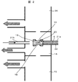
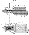
- FIG. 2 shows a configuration diagram of an electron beam sample chamber 14 according to an embodiment and a partially enlarged view of the sample holder 6 for an electron beam apparatus.
- the gas pressure inside the cell 19 is adjusted by the gas pressure control valve 23a from the gas introduction pipe 21a, and the sample 20 is observed inside the gas.
- the gas inside the cell 19 is exhausted from the gas exhaust pipe 22 by the vacuum pump 17.
- the pressure inside the cell 19 is set high by reducing the pressure difference inside and outside the cell 19 by blowing the gas from the gas introduction tube 21b to the electron beam sample chamber 14 and protecting the diaphragm 18.
- the diaphragm 18 is prevented from being broken.
- an intermediate chamber 26 separated by a narrowed wall is provided between the electron beam sample chamber 14 and the electron gun 2, and the gas reaches the electron gun 2 directly by exhausting with a different vacuum pump 17. It is possible to prevent the electron gun 2 from being damaged.
- the material of the diaphragm was an amorphous film composed of light elements such as a carbon film, an oxide film, and a nitride film that can transmit an electron beam.
- a gas having a low electron beam scattering ability for example, hydrogen, oxygen, nitrogen or the like was used.
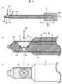
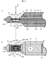
- FIG. 3 shows an overall cross-sectional view (a), a front-end cross-sectional view (b), and a top-end top view (c) of a sample holder 6 for an electron beam apparatus that can move the diaphragm of one embodiment in the horizontal direction.
- the diaphragm 18 is attached to a diaphragm driving unit 27, and the diaphragm driving unit 27 is connected to a micrometer 28 outside the body of the electron beam apparatus 1, and the diaphragm driving unit 27 is operated horizontally by rotating the micrometer 28.
- the sample 20 is fixed to a grid having a diameter of about 3 mm or punched into a disk shape having a diameter of about 3 mm, and is fixed to the cell 19 by a ring spring 32.
- An O-ring 30 is interposed between the diaphragm driving unit 27 and the electron beam apparatus sample holding device 6 body, and the cell 19 is set by setting the diaphragm driving unit 27 so that the part of the diaphragm 18 is disposed in the part where the electron beam 25 passes. It is possible to shut off the atmosphere inside.
- the gas 20 is introduced into the cell 19 from the gas introduction pipe 21a, and the sample 20 in the gas atmosphere can be observed.
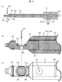
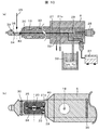
- FIG. 4 is an overall cross-sectional view (a), a front-end cross-sectional view (b), and a front-end top view of the sample holder 6 for an electron beam apparatus when the diaphragm driving unit 27 is moved so as to open the cell 19 of one embodiment.
- the cell 19 can be opened by rotating the micrometer 28 from outside the body of the electron beam apparatus 1, and the gas inside the cell 19 can be exhausted in a short time after the gas reaction, and then the field of view is not lost.
- High-resolution transmission image observation, EDX analysis, and EELS analysis that have been hindered by the diaphragm 18 and gas can be quickly performed.
- FIG. 4 shows a structure in which the upper and lower diaphragms 18 move simultaneously, but a micrometer 28 may be provided so that one or both of the diaphragms 18 horizontally move separately.
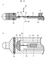
- FIG. 5 illustrates an embodiment in which the diaphragm can be moved in the vertical direction.
- FIG. 5 shows a cross-sectional view of the tip of the sample holder 6 (sample holder) for an electron beam apparatus that can move the diaphragm 18 of one embodiment in the vertical direction.
- the diaphragm 18 is fixed to the presser 31, and the contact portion between the presser 31 and the diaphragm operating part 27 is threaded, so that the diaphragm 18 can move in the vertical direction (a).
- the diaphragm 18 can be brought closer to the sample 20 by screwing the central part of the main body of the sample holder 6 for the electron beam apparatus (b). As a result, the gas volume can be reduced, scattering of the electron beam can be suppressed, and higher resolution observation can be performed.
- the lower diaphragm 18 with respect to the sample 20 is set in the central part of the main body of the sample holder 6 for the electron beam apparatus, and the upper diaphragm 18 is set in the diaphragm driving unit 27 so that only the upper diaphragm 18 can move. It is. Thereby, even when the cell 19 is sealed with the diaphragm 18, the volume of the cell 19 can be reduced, the volume of gas can be suppressed, and high-resolution observation is possible. Further, after the reaction, the upper diaphragm 18 is moved horizontally and the cell 19 is opened, so that the inside of the cell 19 can be exhausted in a short time, and high-resolution observation immediately after the reaction and more sensitive EDX analysis and EELS analysis can be performed. (C) becomes possible.
- FIG. 6 shows an explanatory diagram when the diaphragm 18 is moved in the vertical direction.
- An O-ring 30 is attached to the presser 31 to which the diaphragm 18 is attached, and the inside and outside of the cell 19 are blocked.
- a special screwdriver 33 is used to move the diaphragm 18, and the presser 31 to which the diaphragm 18 is attached is moved up and down by inserting and rotating a protrusion provided on the special driver 33 into a hole provided in the presser 31.
- the sample heating mechanism will be described with reference to FIG.
- FIG. 7 shows a sectional view of the tip (a-1, b-1) and a top view of the tip (a-2, b-2) of the sample holder 6 for an electron beam apparatus according to one embodiment.
- a heater 34 is fixed to the electron beam apparatus sample holder 6 with screws 35 inside the cell 19 of the electron beam apparatus sample holder 6.
- the heater 34 is connected to a heating power source 37 outside the body of the electron beam apparatus 1 via a lead wire 36.
- the sample 20 is powder and is directly attached to the heater 34. By introducing a gas from the gas introduction pipe 21a into the sealed cell 19 and then flowing an electric current through the heater 34, the sample 20 is directly heated, a gas reaction occurs, and the state can be observed. (A-1, 2).
- the gas is exhausted while the current is passed through the heater 34, the upper and lower diaphragms 18 are moved horizontally, and the cell 19 is opened, so that high-resolution observation of the sample 20 immediately after the reaction in the same field of view is possible. Further, even when the electron beam 25 is focused and the EELS analysis of a minute region is performed, analysis with high spatial resolution and no influence of the diaphragm 18 is possible (b-1, 2).
- FIG. 8 shows a sectional view (a) of the tip of the sample holder 6 for an electron beam apparatus according to one embodiment, and a top view (b) of the tip.
- another evaporation heater 34b is provided at the tip of the electron beam apparatus sample holding device 6 in order to deposit a different metal or the like on the sample 20.
- the vapor deposition heater 34 b is installed inside the cell 19 sealed with the diaphragm 18.
- the vapor deposition heater 34b is connected to the lead wire 36b, and is connected to a heating power source different from the heating of the sample 20 via the lead wire 36b.
- a vapor deposition metal 38 is directly attached to the vapor deposition heater 34b. By heating the deposition heater 34b, the deposition metal 38 on the heater 34b is deposited on the sample 20.
- FIG. 9 shows a sectional view (a) of the tip of the sample holder 6 for an electron beam apparatus according to one embodiment and a top view (b) of the tip.
- the tip of the electron beam apparatus sample holder 6 is fixed to a grid having a diameter of about 3 mm or punched into a disk shape having a diameter of about 3 mm.
- a sample 20b is mounted.
- the sample 20 b is fixed in the cell 19 with a ring spring 32.
- the heater 34a can also be used as a deposition source, and different types of deposition sources can be deposited on the sample 20b. It is also possible to heat the sample 20b using the radiant heat of the heater.
- FIG. 10 shows a sectional view (a) of the tip of the sample holder 6 for an electron beam apparatus according to one embodiment and a top view (b) of the tip.
- the sample 20 attached to the tip of the sample holder 6 for electron beam apparatus and the heater 34 can be connected to a heating power source 37 and a liquid nitrogen storage unit 39 via a lead wire 36. Further, a thermocouple 40 is provided in the vicinity of the sample 20 to enable temperature measurement.
- the sample 20 is directly attached to the heater 34, and the sample 20 and the heater 34 can be cooled by connecting to the liquid nitrogen storage unit 39 via the cooling rod 29. Thereby, the reaction of the sample 20 in a wide temperature range can be observed.
- FIG. 11 shows an explanatory diagram when the sample 20 is heated using the present embodiment.
- the magnetic field of the objective lens 4 is in the vertical direction, so that the heater 34 receives a horizontal Lorentz force from the direction of the heating current. .
- FIG. 12 shows a top view of the tip of the sample holder 6 for an electron beam apparatus according to the present embodiment.
- the shape of the diaphragm 18 of the sample holder 6 for an electron beam apparatus is an elliptical shape or a rectangular shape whose long axis matches the moving direction. From FIG. 11, the moving direction of the heater 34 and the sample 20 when the sample 20 is heated is the horizontal direction, so that even if it moves, it is possible to observe without missing the visual field.
- FIG. 13 shows a cross-sectional view (a) and a top view (b) of the tip of the sample holder 6 for an electron beam apparatus according to one embodiment.
- a minute pressure measuring element 41 is provided on the main body of the sample holding device 6 for the electron beam apparatus inside the cell 19 sealed by the diaphragm 18, and is connected to a pressure gauge 42 outside the electron beam apparatus 1. As a result, the pressure inside the cell 19 sealed with the diaphragm 18 can be directly measured.
- FIG. 14 shows an electron beam sample chamber 14 and an electron beam apparatus sample holding device 6 according to an embodiment.
- the electron beam sample chamber 14 is provided in the electron beam apparatus 1 and has a structure in which an electron beam can pass through a central portion indicated by a center line.
- another micro pressure measurement element 41b is provided on the main body of the electron beam apparatus sample holding apparatus 6 outside the cell 19.
- the minute pressure measuring element 41b is connected to the pressure gauge 42b.
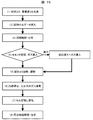
- FIG. 15 is a diagram for explaining the use of the sample holder 6 for an electron beam apparatus according to the embodiment of FIG. (1)
- the sample 20 is attached to the heater 34a. Further, a different metal 38 for vapor deposition is attached to the sample 20 to the vapor deposition heater 34b.
- (3) The sample 20 is observed without the diaphragm 18. If necessary, perform EDX analysis and EELS analysis.
- the cell 19 is sealed with the diaphragm 18.
- a gas such as air is introduced to set the pressure in the cell 19. If there is a possibility that the diaphragm 18 may be damaged due to high pressure, gas is also introduced into the outside of the cell 19, that is, the electron beam sample chamber 14.
- Heat the sample 20 Observe and analyze the gas reaction of the sample due to heating. (6) Stop the heating after the reaction.
- the diaphragm 18 is moved horizontally, and the gas inside and outside the cell 19 is exhausted. (8) High resolution observation and
- the reaction process in the gas atmosphere can be freely observed without taking out the sample 20 from the electron beam apparatus 1 while maintaining the observation visual field, and furthermore, high-resolution observation and analysis are possible. .
- the pressure in the environmental cell is accurately controlled, and the reaction process in high-pressure gas atmosphere or liquid, for example, crystal growth process by high-temperature gas reaction, observation of oxidation-reduction reaction, micro atmospheric space It is possible to observe living organisms, etc., and perform high-resolution observation and high-sensitivity analysis immediately after reaction in a high-pressure gas atmosphere.
Landscapes
- Chemical & Material Sciences (AREA)
- Analytical Chemistry (AREA)
- Analysing Materials By The Use Of Radiation (AREA)
Priority Applications (2)
| Application Number | Priority Date | Filing Date | Title |
|---|---|---|---|
| EP10741027.6A EP2398036B1 (en) | 2009-02-16 | 2010-01-20 | Electron beam device and sample holding device for electron beam device |
| US13/201,820 US8604429B2 (en) | 2009-02-16 | 2010-01-20 | Electron beam device and sample holding device for electron beam device |
Applications Claiming Priority (2)
| Application Number | Priority Date | Filing Date | Title |
|---|---|---|---|
| JP2009-032124 | 2009-02-16 | ||
| JP2009032124A JP5124507B2 (ja) | 2009-02-16 | 2009-02-16 | 電子線装置および電子線装置用試料保持装置 |
Publications (1)
| Publication Number | Publication Date |
|---|---|
| WO2010092747A1 true WO2010092747A1 (ja) | 2010-08-19 |
Family
ID=42561596
Family Applications (1)
| Application Number | Title | Priority Date | Filing Date |
|---|---|---|---|
| PCT/JP2010/000282 Ceased WO2010092747A1 (ja) | 2009-02-16 | 2010-01-20 | 電子線装置および電子線装置用試料保持装置 |
Country Status (4)
| Country | Link |
|---|---|
| US (1) | US8604429B2 (enExample) |
| EP (1) | EP2398036B1 (enExample) |
| JP (1) | JP5124507B2 (enExample) |
| WO (1) | WO2010092747A1 (enExample) |
Cited By (5)
| Publication number | Priority date | Publication date | Assignee | Title |
|---|---|---|---|---|
| WO2011104801A1 (ja) * | 2010-02-24 | 2011-09-01 | 株式会社 日立ハイテクノロジーズ | 電子顕微鏡、および試料ホルダ |
| WO2012140822A1 (ja) * | 2011-04-11 | 2012-10-18 | 株式会社 日立ハイテクノロジーズ | 荷電粒子線装置 |
| US20150179396A1 (en) * | 2012-07-27 | 2015-06-25 | Hitachi High-Technologies Corporation | Electron microscope and electron microscope sample retaining device |
| WO2017033219A1 (ja) * | 2015-08-21 | 2017-03-02 | 株式会社 日立ハイテクノロジーズ | 荷電粒子顕微鏡の観察支援ユニットおよびこれを用いた試料観察方法 |
| DE112012001306B4 (de) | 2011-04-28 | 2022-03-24 | Hitachi High-Tech Corporation | Probenhaltevorrichtung, Elektronenmikroskop und Probenhalterung |
Families Citing this family (19)
| Publication number | Priority date | Publication date | Assignee | Title |
|---|---|---|---|---|
| EP2481073A4 (en) * | 2009-09-24 | 2014-10-15 | Protochips Inc | METHODS OF USING TEMPERATURE REGULATION DEVICES IN ELECTRON MICROSCOPY |
| JP6014036B2 (ja) * | 2010-08-02 | 2016-10-25 | プロトチップス,インコーポレイテッド | 2つの半導体デバイスでガスまたは液体セルを形成するための電子顕微鏡サンプルホルダ |
| JP5576825B2 (ja) * | 2011-05-13 | 2014-08-20 | 日本電子株式会社 | 電子線装置及び電子顕微鏡用ガス反応試料ホルダ |
| JP5824262B2 (ja) * | 2011-07-08 | 2015-11-25 | 日本電子株式会社 | 試料観察方法および圧力測定用ホルダ |
| EP2555221B1 (en) * | 2011-08-03 | 2013-07-24 | Fei Company | Method of studying a sample in an ETEM |
| US9437393B2 (en) | 2012-11-16 | 2016-09-06 | Protochips, Inc. | Method for forming an electrical connection to an sample support in an electron microscope holder |
| DE112014001109B4 (de) * | 2013-04-12 | 2019-11-14 | Hitachi High-Technologies Corporation | Mit einem Strahl geladener Teilchen arbeitende Vorrichtung und Filterelement |
| JP6117070B2 (ja) | 2013-09-26 | 2017-04-19 | 株式会社日立ハイテクノロジーズ | 電子顕微鏡 |
| JP6364167B2 (ja) * | 2013-09-30 | 2018-07-25 | 株式会社日立ハイテクノロジーズ | 環境制御型荷電粒子観察システム |
| JP6373568B2 (ja) * | 2013-10-07 | 2018-08-15 | 株式会社日立ハイテクノロジーズ | 荷電粒子線装置 |
| DE102014103360A1 (de) | 2014-03-12 | 2015-09-17 | Leibniz-Institut Für Neue Materialien Gemeinnützige Gmbh | Vorrichtung für die korrelative Raster-Transmissionselektronenmikroskopie (STEM) und Lichtmikroskopie |
| US9466459B2 (en) | 2014-06-03 | 2016-10-11 | Protochips, Inc. | Method for optimizing fluid flow across a sample within an electron microscope sample holder |
| DE102014108331A1 (de) | 2014-06-13 | 2015-12-17 | Leibniz-Institut Für Neue Materialien Gemeinnützige Gesellschaft Mit Beschränkter Haftung | Spezifische Proteinmarkierung sowie Verfahren zur Identifizierung der statistischen Verteilung der Proteinstöchiometrie |
| DE102014108825A1 (de) * | 2014-06-24 | 2015-12-24 | Leibniz-Institut Für Neue Materialien Gemeinnützige Gesellschaft Mit Beschränkter Haftung | Vorrichtung und Verfahren für die stöchiometrische Analyse von Proben |
| JP6774761B2 (ja) * | 2016-02-05 | 2020-10-28 | 日本電子株式会社 | 試料ホルダー |
| WO2018207309A1 (ja) * | 2017-05-11 | 2018-11-15 | 株式会社日立ハイテクノロジーズ | 試料ホルダ、電子顕微鏡 |
| JP7493101B2 (ja) * | 2021-04-13 | 2024-05-30 | 株式会社日立ハイテク | 透過型電子顕微鏡 |
| JP7585153B2 (ja) * | 2021-07-13 | 2024-11-18 | 株式会社日立製作所 | 試料ホルダー及び電子顕微鏡 |
| JP7769098B2 (ja) * | 2022-03-15 | 2025-11-12 | 株式会社日立製作所 | 試料保持具、電子線装置、試料保持具の製造方法 |
Citations (12)
| Publication number | Priority date | Publication date | Assignee | Title |
|---|---|---|---|---|
| JPS4724960U (enExample) * | 1971-04-14 | 1972-11-20 | ||
| JPS51267A (en) | 1974-06-19 | 1976-01-05 | Hitachi Ltd | Denshikenbikyotono shiryohojisochi |
| JPH0222559U (enExample) * | 1988-07-29 | 1990-02-15 | ||
| US5326971A (en) | 1993-05-17 | 1994-07-05 | Motorola, Inc. | Transmission electron microscope environmental specimen holder |
| JPH09129168A (ja) | 1995-11-01 | 1997-05-16 | Jeol Ltd | 隔膜型ガス雰囲気試料室を有する試料ホルダ |
| JP2000133186A (ja) | 1998-10-27 | 2000-05-12 | Jeol Ltd | ガス雰囲気試料ホルダ |
| JP2000208083A (ja) | 1999-01-20 | 2000-07-28 | Jeol Ltd | 電子顕微鏡の試料冷却装置 |
| JP2001305028A (ja) | 2000-04-25 | 2001-10-31 | Nippon Steel Corp | 固相反応試料の透過電子顕微鏡観察用試料作製方法および荷電粒子ビーム装置 |
| JP2003187735A (ja) | 2001-12-18 | 2003-07-04 | Jeol Ltd | 試料ホルダ |
| JP2005190864A (ja) | 2003-12-26 | 2005-07-14 | Hitachi High-Technologies Corp | 電子線装置及び電子線装置用試料ホルダー |
| JP2008108429A (ja) | 2006-10-23 | 2008-05-08 | Hitachi High-Technologies Corp | 荷電粒子線装置および荷電粒子線装置用試料保持装置 |
| JP2009117196A (ja) * | 2007-11-07 | 2009-05-28 | Jeol Ltd | 隔膜型ガス雰囲気試料ホルダ |
Family Cites Families (9)
| Publication number | Priority date | Publication date | Assignee | Title |
|---|---|---|---|---|
| FR2629915B1 (fr) | 1988-04-08 | 1992-10-23 | Lefel Marie France | Procede de detection de traces de stupefiants et produits pour la mise en oeuvre de ce procede |
| IL156027A0 (en) | 2000-12-01 | 2003-12-23 | El Mul Technologies Ltd | Device and method for the examination of samples in a non-vacuum environment using a scanning electron microscope |
| JP2003115273A (ja) * | 2001-10-03 | 2003-04-18 | Jeol Ltd | 試料ホルダー及び電子顕微鏡 |
| JP4723414B2 (ja) * | 2006-04-27 | 2011-07-13 | 株式会社日立ハイテクノロジーズ | 走査電子顕微鏡 |
| CN101461026B (zh) * | 2006-06-07 | 2012-01-18 | Fei公司 | 与包含真空室的装置一起使用的滑动轴承 |
| JP4991390B2 (ja) * | 2007-05-21 | 2012-08-01 | 株式会社日立ハイテクノロジーズ | マイクロサンプル加熱用試料台 |
| JP2010230417A (ja) * | 2009-03-26 | 2010-10-14 | Jeol Ltd | 試料の検査装置及び検査方法 |
| JP5260575B2 (ja) * | 2010-02-24 | 2013-08-14 | 株式会社日立ハイテクノロジーズ | 電子顕微鏡、および試料ホルダ |
| US9207196B2 (en) * | 2010-11-17 | 2015-12-08 | Vanderbilt University | Transmission electron microscopy for imaging live cells |
-
2009
- 2009-02-16 JP JP2009032124A patent/JP5124507B2/ja active Active
-
2010
- 2010-01-20 EP EP10741027.6A patent/EP2398036B1/en not_active Not-in-force
- 2010-01-20 US US13/201,820 patent/US8604429B2/en active Active
- 2010-01-20 WO PCT/JP2010/000282 patent/WO2010092747A1/ja not_active Ceased
Patent Citations (12)
| Publication number | Priority date | Publication date | Assignee | Title |
|---|---|---|---|---|
| JPS4724960U (enExample) * | 1971-04-14 | 1972-11-20 | ||
| JPS51267A (en) | 1974-06-19 | 1976-01-05 | Hitachi Ltd | Denshikenbikyotono shiryohojisochi |
| JPH0222559U (enExample) * | 1988-07-29 | 1990-02-15 | ||
| US5326971A (en) | 1993-05-17 | 1994-07-05 | Motorola, Inc. | Transmission electron microscope environmental specimen holder |
| JPH09129168A (ja) | 1995-11-01 | 1997-05-16 | Jeol Ltd | 隔膜型ガス雰囲気試料室を有する試料ホルダ |
| JP2000133186A (ja) | 1998-10-27 | 2000-05-12 | Jeol Ltd | ガス雰囲気試料ホルダ |
| JP2000208083A (ja) | 1999-01-20 | 2000-07-28 | Jeol Ltd | 電子顕微鏡の試料冷却装置 |
| JP2001305028A (ja) | 2000-04-25 | 2001-10-31 | Nippon Steel Corp | 固相反応試料の透過電子顕微鏡観察用試料作製方法および荷電粒子ビーム装置 |
| JP2003187735A (ja) | 2001-12-18 | 2003-07-04 | Jeol Ltd | 試料ホルダ |
| JP2005190864A (ja) | 2003-12-26 | 2005-07-14 | Hitachi High-Technologies Corp | 電子線装置及び電子線装置用試料ホルダー |
| JP2008108429A (ja) | 2006-10-23 | 2008-05-08 | Hitachi High-Technologies Corp | 荷電粒子線装置および荷電粒子線装置用試料保持装置 |
| JP2009117196A (ja) * | 2007-11-07 | 2009-05-28 | Jeol Ltd | 隔膜型ガス雰囲気試料ホルダ |
Non-Patent Citations (1)
| Title |
|---|
| See also references of EP2398036A4 |
Cited By (16)
| Publication number | Priority date | Publication date | Assignee | Title |
|---|---|---|---|---|
| JP2011175809A (ja) * | 2010-02-24 | 2011-09-08 | Hitachi High-Technologies Corp | 電子顕微鏡、および試料ホルダ |
| US8878144B2 (en) | 2010-02-24 | 2014-11-04 | Hitachi High-Technologies Corporation | Electron microscope and sample holder |
| WO2011104801A1 (ja) * | 2010-02-24 | 2011-09-01 | 株式会社 日立ハイテクノロジーズ | 電子顕微鏡、および試料ホルダ |
| CN103477415B (zh) * | 2011-04-11 | 2016-10-12 | 株式会社日立高新技术 | 带电粒子束装置及利用带电粒子束装置进行观察的方法 |
| WO2012140822A1 (ja) * | 2011-04-11 | 2012-10-18 | 株式会社 日立ハイテクノロジーズ | 荷電粒子線装置 |
| JP2012221766A (ja) * | 2011-04-11 | 2012-11-12 | Hitachi High-Technologies Corp | 荷電粒子線装置 |
| CN103477415A (zh) * | 2011-04-11 | 2013-12-25 | 株式会社日立高新技术 | 带电粒子束装置 |
| US8710439B2 (en) | 2011-04-11 | 2014-04-29 | Hitachi High-Technologies Corporation | Charged particle beam apparatus |
| US8921786B2 (en) | 2011-04-11 | 2014-12-30 | Hitachi High-Technologies Corporation | Charged particle beam apparatus |
| US9105442B2 (en) | 2011-04-11 | 2015-08-11 | Hitachi High-Technologies Corporation | Charged particle beam apparatus |
| DE112012001306B4 (de) | 2011-04-28 | 2022-03-24 | Hitachi High-Tech Corporation | Probenhaltevorrichtung, Elektronenmikroskop und Probenhalterung |
| US20150179396A1 (en) * | 2012-07-27 | 2015-06-25 | Hitachi High-Technologies Corporation | Electron microscope and electron microscope sample retaining device |
| US9378922B2 (en) * | 2012-07-27 | 2016-06-28 | Hitachi High-Technologies Corporation | Electron microscope and electron microscope sample retaining device |
| WO2017033219A1 (ja) * | 2015-08-21 | 2017-03-02 | 株式会社 日立ハイテクノロジーズ | 荷電粒子顕微鏡の観察支援ユニットおよびこれを用いた試料観察方法 |
| JPWO2017033219A1 (ja) * | 2015-08-21 | 2018-06-14 | 株式会社日立ハイテクノロジーズ | 観察支援ユニットおよびこれを用いた試料観察方法、荷電粒子線装置 |
| US10431416B2 (en) | 2015-08-21 | 2019-10-01 | Hitachi High-Technologies Corporation | Observation support unit for charged particle microscope and sample observation method using same |
Also Published As
| Publication number | Publication date |
|---|---|
| EP2398036A1 (en) | 2011-12-21 |
| EP2398036B1 (en) | 2014-10-01 |
| JP5124507B2 (ja) | 2013-01-23 |
| JP2010192126A (ja) | 2010-09-02 |
| US8604429B2 (en) | 2013-12-10 |
| US20110303845A1 (en) | 2011-12-15 |
| EP2398036A4 (en) | 2013-01-09 |
Similar Documents
| Publication | Publication Date | Title |
|---|---|---|
| JP5124507B2 (ja) | 電子線装置および電子線装置用試料保持装置 | |
| JP5260575B2 (ja) | 電子顕微鏡、および試料ホルダ | |
| EP2555221B1 (en) | Method of studying a sample in an ETEM | |
| US8779380B2 (en) | Ion beam device | |
| US8710439B2 (en) | Charged particle beam apparatus | |
| JP6093752B2 (ja) | イオンビーム装置 | |
| US20160217971A1 (en) | Charged Particle Beam Device and Sample Holder for Charged Particle Beam Device | |
| EP2495748B1 (en) | Charged particle radiation apparatus, and method for displaying three-dimensional information in charged particle radiation apparatus | |
| US20140123898A1 (en) | Charged particle beam device | |
| JP4850654B2 (ja) | 荷電粒子線装置および荷電粒子線装置用試料保持装置 | |
| US12002656B2 (en) | Operating a gas feed device for a particle beam apparatus | |
| US20230221268A1 (en) | Observation device for observation target gas, method of observing target ions, and sample holder | |
| WO2016056446A1 (ja) | イオンビーム装置 | |
| US12387904B2 (en) | Examining, analyzing and/or processing an object using an object receiving container | |
| WO2015045477A1 (ja) | 試料ホールダ及び荷電粒子装置 | |
| JP2013134814A (ja) | 電子顕微鏡および電子顕微鏡用試料保持装置 | |
| JP5824262B2 (ja) | 試料観察方法および圧力測定用ホルダ | |
| JP7407689B2 (ja) | 試料ホルダ及びそれを備える荷電粒子線装置 |
Legal Events
| Date | Code | Title | Description |
|---|---|---|---|
| 121 | Ep: the epo has been informed by wipo that ep was designated in this application |
Ref document number: 10741027 Country of ref document: EP Kind code of ref document: A1 |
|
| NENP | Non-entry into the national phase |
Ref country code: DE |
|
| WWE | Wipo information: entry into national phase |
Ref document number: 13201820 Country of ref document: US Ref document number: 2010741027 Country of ref document: EP |