WO2010079051A1 - Silyl- und heteroatom-substituierte verbindungen ausgewählt aus carbazolen, dibenzofuranen, dibenzothiophenen und dibenzophospholen und ihre anwendung in der organischen elektronik - Google Patents
Silyl- und heteroatom-substituierte verbindungen ausgewählt aus carbazolen, dibenzofuranen, dibenzothiophenen und dibenzophospholen und ihre anwendung in der organischen elektronik Download PDFInfo
- Publication number
- WO2010079051A1 WO2010079051A1 PCT/EP2009/067120 EP2009067120W WO2010079051A1 WO 2010079051 A1 WO2010079051 A1 WO 2010079051A1 EP 2009067120 W EP2009067120 W EP 2009067120W WO 2010079051 A1 WO2010079051 A1 WO 2010079051A1
- Authority
- WO
- WIPO (PCT)
- Prior art keywords
- group
- radicals
- formula
- aryl
- compound
- Prior art date
Links
- 150000001875 compounds Chemical class 0.000 title claims abstract description 212
- 125000005842 heteroatom Chemical group 0.000 title claims abstract description 23
- IYYZUPMFVPLQIF-UHFFFAOYSA-N dibenzothiophene Chemical class C1=CC=C2C3=CC=CC=C3SC2=C1 IYYZUPMFVPLQIF-UHFFFAOYSA-N 0.000 title abstract description 17
- 150000001716 carbazoles Chemical class 0.000 title abstract description 10
- 150000004826 dibenzofurans Chemical class 0.000 title abstract description 8
- 125000001181 organosilyl group Chemical group [SiH3]* 0.000 title abstract description 3
- 150000004857 phospholes Chemical class 0.000 title 1
- 230000000903 blocking effect Effects 0.000 claims abstract description 6
- 239000000463 material Substances 0.000 claims description 195
- -1 2,5-dihydro-1-pyrrolyl Chemical group 0.000 claims description 155
- 125000003118 aryl group Chemical group 0.000 claims description 75
- 239000004020 conductor Substances 0.000 claims description 68
- 125000000217 alkyl group Chemical group 0.000 claims description 62
- 125000001072 heteroaryl group Chemical group 0.000 claims description 55
- RTZKZFJDLAIYFH-UHFFFAOYSA-N Diethyl ether Chemical compound CCOCC RTZKZFJDLAIYFH-UHFFFAOYSA-N 0.000 claims description 52
- 239000011159 matrix material Substances 0.000 claims description 52
- 125000000753 cycloalkyl group Chemical group 0.000 claims description 46
- 125000000592 heterocycloalkyl group Chemical group 0.000 claims description 45
- 239000000203 mixture Substances 0.000 claims description 45
- 238000000034 method Methods 0.000 claims description 41
- 125000001424 substituent group Chemical group 0.000 claims description 40
- 238000002347 injection Methods 0.000 claims description 37
- 239000007924 injection Substances 0.000 claims description 37
- 229910052751 metal Inorganic materials 0.000 claims description 30
- 239000002184 metal Substances 0.000 claims description 30
- 125000006850 spacer group Chemical group 0.000 claims description 28
- 229910052760 oxygen Inorganic materials 0.000 claims description 27
- 229910052717 sulfur Inorganic materials 0.000 claims description 27
- 238000002360 preparation method Methods 0.000 claims description 24
- 125000004432 carbon atom Chemical group C* 0.000 claims description 23
- 239000002243 precursor Substances 0.000 claims description 17
- 238000006243 chemical reaction Methods 0.000 claims description 16
- 238000006116 polymerization reaction Methods 0.000 claims description 15
- 239000002904 solvent Substances 0.000 claims description 15
- SVSARCCKBMZNMR-UHFFFAOYSA-N [1-[2-[methyl-[2-[4-(oxoazaniumylmethylidene)pyridin-1-yl]ethyl]amino]ethyl]pyridin-4-ylidene]methyl-oxoazanium;dichloride Chemical compound [Cl-].[Cl-].C1=CC(=C[NH+]=O)C=CN1CCN(C)CCN1C=CC(=C[NH+]=O)C=C1 SVSARCCKBMZNMR-UHFFFAOYSA-N 0.000 claims description 14
- 238000005859 coupling reaction Methods 0.000 claims description 13
- 238000004519 manufacturing process Methods 0.000 claims description 11
- 125000006413 ring segment Chemical group 0.000 claims description 11
- 230000008569 process Effects 0.000 claims description 8
- 125000000609 carbazolyl group Chemical group C1(=CC=CC=2C3=CC=CC=C3NC12)* 0.000 claims description 7
- 230000000694 effects Effects 0.000 claims description 7
- 125000004429 atom Chemical group 0.000 claims description 6
- 125000004433 nitrogen atom Chemical group N* 0.000 claims description 6
- 239000003153 chemical reaction reagent Substances 0.000 claims description 5
- 238000004132 cross linking Methods 0.000 claims description 5
- 125000000524 functional group Chemical group 0.000 claims description 4
- 125000002883 imidazolyl group Chemical group 0.000 claims description 4
- 125000001041 indolyl group Chemical group 0.000 claims description 4
- 125000000168 pyrrolyl group Chemical group 0.000 claims description 4
- 229920006395 saturated elastomer Polymers 0.000 claims description 4
- 239000004593 Epoxy Substances 0.000 claims description 3
- 150000001252 acrylic acid derivatives Chemical class 0.000 claims description 3
- 125000003785 benzimidazolyl group Chemical group N1=C(NC2=C1C=CC=C2)* 0.000 claims description 3
- 150000002734 metacrylic acid derivatives Chemical class 0.000 claims description 3
- 125000001399 1,2,3-triazolyl group Chemical group N1N=NC(=C1)* 0.000 claims description 2
- 125000001376 1,2,4-triazolyl group Chemical group N1N=C(N=C1)* 0.000 claims description 2
- 125000003354 benzotriazolyl group Chemical group N1N=NC2=C1C=CC=C2* 0.000 claims description 2
- 125000002091 cationic group Chemical group 0.000 claims description 2
- 150000002170 ethers Chemical class 0.000 claims description 2
- 238000009472 formulation Methods 0.000 claims description 2
- 125000003453 indazolyl group Chemical group N1N=C(C2=C1C=CC=C2)* 0.000 claims description 2
- 125000003387 indolinyl group Chemical group N1(CCC2=CC=CC=C12)* 0.000 claims description 2
- 125000004594 isoindolinyl group Chemical group C1(NCC2=CC=CC=C12)* 0.000 claims description 2
- 125000002757 morpholinyl group Chemical group 0.000 claims description 2
- 125000003566 oxetanyl group Chemical group 0.000 claims description 2
- 125000005936 piperidyl group Chemical group 0.000 claims description 2
- 125000003226 pyrazolyl group Chemical group 0.000 claims description 2
- 125000000719 pyrrolidinyl group Chemical group 0.000 claims description 2
- 125000003831 tetrazolyl group Chemical group 0.000 claims description 2
- 239000010410 layer Substances 0.000 description 217
- 150000003254 radicals Chemical class 0.000 description 84
- 239000000243 solution Substances 0.000 description 71
- 230000015572 biosynthetic process Effects 0.000 description 64
- 238000003786 synthesis reaction Methods 0.000 description 64
- YMWUJEATGCHHMB-UHFFFAOYSA-N Dichloromethane Chemical compound ClCCl YMWUJEATGCHHMB-UHFFFAOYSA-N 0.000 description 60
- WYURNTSHIVDZCO-UHFFFAOYSA-N Tetrahydrofuran Chemical compound C1CCOC1 WYURNTSHIVDZCO-UHFFFAOYSA-N 0.000 description 58
- 229910052741 iridium Inorganic materials 0.000 description 56
- GKOZUEZYRPOHIO-UHFFFAOYSA-N iridium atom Chemical compound [Ir] GKOZUEZYRPOHIO-UHFFFAOYSA-N 0.000 description 54
- VLKZOEOYAKHREP-UHFFFAOYSA-N n-Hexane Chemical compound CCCCCC VLKZOEOYAKHREP-UHFFFAOYSA-N 0.000 description 54
- MZRVEZGGRBJDDB-UHFFFAOYSA-N n-Butyllithium Substances [Li]CCCC MZRVEZGGRBJDDB-UHFFFAOYSA-N 0.000 description 43
- 229910052757 nitrogen Inorganic materials 0.000 description 42
- 239000000047 product Substances 0.000 description 41
- OKKJLVBELUTLKV-UHFFFAOYSA-N Methanol Chemical compound OC OKKJLVBELUTLKV-UHFFFAOYSA-N 0.000 description 39
- XKRFYHLGVUSROY-UHFFFAOYSA-N Argon Chemical compound [Ar] XKRFYHLGVUSROY-UHFFFAOYSA-N 0.000 description 38
- 238000005160 1H NMR spectroscopy Methods 0.000 description 28
- IIYFAKIEWZDVMP-UHFFFAOYSA-N tridecane Chemical compound CCCCCCCCCCCCC IIYFAKIEWZDVMP-UHFFFAOYSA-N 0.000 description 28
- UJOBWOGCFQCDNV-UHFFFAOYSA-N 9H-carbazole Chemical compound C1=CC=C2C3=CC=CC=C3NC2=C1 UJOBWOGCFQCDNV-UHFFFAOYSA-N 0.000 description 27
- 229910004298 SiO 2 Inorganic materials 0.000 description 25
- POILWHVDKZOXJZ-ARJAWSKDSA-M (z)-4-oxopent-2-en-2-olate Chemical compound C\C([O-])=C\C(C)=O POILWHVDKZOXJZ-ARJAWSKDSA-M 0.000 description 23
- 239000007983 Tris buffer Substances 0.000 description 22
- BWHMMNNQKKPAPP-UHFFFAOYSA-L potassium carbonate Chemical compound [K+].[K+].[O-]C([O-])=O BWHMMNNQKKPAPP-UHFFFAOYSA-L 0.000 description 22
- HEMHJVSKTPXQMS-UHFFFAOYSA-M Sodium hydroxide Chemical compound [OH-].[Na+] HEMHJVSKTPXQMS-UHFFFAOYSA-M 0.000 description 21
- 229910052736 halogen Inorganic materials 0.000 description 21
- HEDRZPFGACZZDS-UHFFFAOYSA-N Chloroform Chemical compound ClC(Cl)Cl HEDRZPFGACZZDS-UHFFFAOYSA-N 0.000 description 20
- XDTMQSROBMDMFD-UHFFFAOYSA-N Cyclohexane Chemical compound C1CCCCC1 XDTMQSROBMDMFD-UHFFFAOYSA-N 0.000 description 19
- 229910052786 argon Inorganic materials 0.000 description 19
- 150000002367 halogens Chemical group 0.000 description 19
- 239000012074 organic phase Substances 0.000 description 19
- CSCPPACGZOOCGX-UHFFFAOYSA-N Acetone Chemical compound CC(C)=O CSCPPACGZOOCGX-UHFFFAOYSA-N 0.000 description 18
- 125000001997 phenyl group Chemical group [H]C1=C([H])C([H])=C(*)C([H])=C1[H] 0.000 description 18
- ZMXDDKWLCZADIW-UHFFFAOYSA-N N,N-Dimethylformamide Chemical compound CN(C)C=O ZMXDDKWLCZADIW-UHFFFAOYSA-N 0.000 description 16
- 239000011734 sodium Substances 0.000 description 16
- 239000000758 substrate Substances 0.000 description 15
- RYGMFSIKBFXOCR-UHFFFAOYSA-N Copper Chemical compound [Cu] RYGMFSIKBFXOCR-UHFFFAOYSA-N 0.000 description 14
- 229910052740 iodine Inorganic materials 0.000 description 14
- 229920000642 polymer Polymers 0.000 description 14
- 230000032258 transport Effects 0.000 description 14
- XLYOFNOQVPJJNP-UHFFFAOYSA-N water Substances O XLYOFNOQVPJJNP-UHFFFAOYSA-N 0.000 description 14
- UHOVQNZJYSORNB-UHFFFAOYSA-N Benzene Chemical compound C1=CC=CC=C1 UHOVQNZJYSORNB-UHFFFAOYSA-N 0.000 description 12
- 239000002800 charge carrier Substances 0.000 description 12
- 238000001816 cooling Methods 0.000 description 12
- TXCDCPKCNAJMEE-UHFFFAOYSA-N dibenzofuran Chemical compound C1=CC=C2C3=CC=CC=C3OC2=C1 TXCDCPKCNAJMEE-UHFFFAOYSA-N 0.000 description 12
- PQXKHYXIUOZZFA-UHFFFAOYSA-M lithium fluoride Chemical compound [Li+].[F-] PQXKHYXIUOZZFA-UHFFFAOYSA-M 0.000 description 12
- HZVOZRGWRWCICA-UHFFFAOYSA-N methanediyl Chemical class [CH2] HZVOZRGWRWCICA-UHFFFAOYSA-N 0.000 description 12
- HAKJPFBYGDBEEA-UHFFFAOYSA-N triphenyl-(9-phenyl-6-triphenylsilylcarbazol-3-yl)silane Chemical compound C1=CC=CC=C1N1C2=CC=C([Si](C=3C=CC=CC=3)(C=3C=CC=CC=3)C=3C=CC=CC=3)C=C2C2=CC([Si](C=3C=CC=CC=3)(C=3C=CC=CC=3)C=3C=CC=CC=3)=CC=C21 HAKJPFBYGDBEEA-UHFFFAOYSA-N 0.000 description 12
- WEVYAHXRMPXWCK-UHFFFAOYSA-N Acetonitrile Chemical compound CC#N WEVYAHXRMPXWCK-UHFFFAOYSA-N 0.000 description 11
- LFQSCWFLJHTTHZ-UHFFFAOYSA-N Ethanol Chemical compound CCO LFQSCWFLJHTTHZ-UHFFFAOYSA-N 0.000 description 11
- 230000009471 action Effects 0.000 description 11
- 229910000027 potassium carbonate Inorganic materials 0.000 description 11
- 239000002585 base Substances 0.000 description 10
- 150000002739 metals Chemical class 0.000 description 10
- YXFVVABEGXRONW-UHFFFAOYSA-N Toluene Chemical compound CC1=CC=CC=C1 YXFVVABEGXRONW-UHFFFAOYSA-N 0.000 description 9
- 150000005840 aryl radicals Chemical class 0.000 description 9
- 238000010168 coupling process Methods 0.000 description 9
- 229910052731 fluorine Inorganic materials 0.000 description 9
- 125000004435 hydrogen atom Chemical group [H]* 0.000 description 9
- 238000006884 silylation reaction Methods 0.000 description 9
- IMNFDUFMRHMDMM-UHFFFAOYSA-N N-Heptane Chemical compound CCCCCCC IMNFDUFMRHMDMM-UHFFFAOYSA-N 0.000 description 8
- 229910052783 alkali metal Inorganic materials 0.000 description 8
- 229910052794 bromium Inorganic materials 0.000 description 8
- MNKYQPOFRKPUAE-UHFFFAOYSA-N chloro(triphenyl)silane Chemical compound C=1C=CC=CC=1[Si](C=1C=CC=CC=1)(Cl)C1=CC=CC=C1 MNKYQPOFRKPUAE-UHFFFAOYSA-N 0.000 description 8
- 230000000052 comparative effect Effects 0.000 description 8
- 230000008878 coupling Effects 0.000 description 8
- 239000012044 organic layer Substances 0.000 description 8
- IXHWGNYCZPISET-UHFFFAOYSA-N 2-[4-(dicyanomethylidene)-2,3,5,6-tetrafluorocyclohexa-2,5-dien-1-ylidene]propanedinitrile Chemical compound FC1=C(F)C(=C(C#N)C#N)C(F)=C(F)C1=C(C#N)C#N IXHWGNYCZPISET-UHFFFAOYSA-N 0.000 description 7
- 238000006254 arylation reaction Methods 0.000 description 7
- 125000006239 protecting group Chemical group 0.000 description 7
- 238000003756 stirring Methods 0.000 description 7
- LZHVTCXAXYYCIF-UHFFFAOYSA-N 2-n',2-n',7-n',7-n'-tetrakis(4-methoxyphenyl)-9,9'-spirobi[fluorene]-2',7'-diamine Chemical compound C1=CC(OC)=CC=C1N(C=1C=C2C3(C4=CC=CC=C4C4=CC=CC=C43)C3=CC(=CC=C3C2=CC=1)N(C=1C=CC(OC)=CC=1)C=1C=CC(OC)=CC=1)C1=CC=C(OC)C=C1 LZHVTCXAXYYCIF-UHFFFAOYSA-N 0.000 description 6
- FSEXLNMNADBYJU-UHFFFAOYSA-N 2-phenylquinoline Chemical compound C1=CC=CC=C1C1=CC=C(C=CC=C2)C2=N1 FSEXLNMNADBYJU-UHFFFAOYSA-N 0.000 description 6
- WPUSEOSICYGUEW-UHFFFAOYSA-N 4-[4-(4-methoxy-n-(4-methoxyphenyl)anilino)phenyl]-n,n-bis(4-methoxyphenyl)aniline Chemical compound C1=CC(OC)=CC=C1N(C=1C=CC(=CC=1)C=1C=CC(=CC=1)N(C=1C=CC(OC)=CC=1)C=1C=CC(OC)=CC=1)C1=CC=C(OC)C=C1 WPUSEOSICYGUEW-UHFFFAOYSA-N 0.000 description 6
- IJGRMHOSHXDMSA-UHFFFAOYSA-N Atomic nitrogen Chemical compound N#N IJGRMHOSHXDMSA-UHFFFAOYSA-N 0.000 description 6
- IAZDPXIOMUYVGZ-UHFFFAOYSA-N Dimethylsulphoxide Chemical compound CS(C)=O IAZDPXIOMUYVGZ-UHFFFAOYSA-N 0.000 description 6
- VEXZGXHMUGYJMC-UHFFFAOYSA-N Hydrochloric acid Chemical compound Cl VEXZGXHMUGYJMC-UHFFFAOYSA-N 0.000 description 6
- KFZMGEQAYNKOFK-UHFFFAOYSA-N Isopropanol Chemical compound CC(C)O KFZMGEQAYNKOFK-UHFFFAOYSA-N 0.000 description 6
- CBENFWSGALASAD-UHFFFAOYSA-N Ozone Chemical compound [O-][O+]=O CBENFWSGALASAD-UHFFFAOYSA-N 0.000 description 6
- OFBQJSOFQDEBGM-UHFFFAOYSA-N Pentane Chemical compound CCCCC OFBQJSOFQDEBGM-UHFFFAOYSA-N 0.000 description 6
- 239000002253 acid Substances 0.000 description 6
- 150000001340 alkali metals Chemical class 0.000 description 6
- 150000001502 aryl halides Chemical class 0.000 description 6
- 229910052799 carbon Inorganic materials 0.000 description 6
- 229910052801 chlorine Inorganic materials 0.000 description 6
- 125000001495 ethyl group Chemical group [H]C([H])([H])C([H])([H])* 0.000 description 6
- 230000006870 function Effects 0.000 description 6
- 230000005525 hole transport Effects 0.000 description 6
- 229910052739 hydrogen Inorganic materials 0.000 description 6
- 239000001257 hydrogen Substances 0.000 description 6
- 125000002496 methyl group Chemical group [H]C([H])([H])* 0.000 description 6
- 239000011368 organic material Substances 0.000 description 6
- LYKXFSYCKWNWEZ-UHFFFAOYSA-N pyrazino[2,3-f][1,10]phenanthroline-2,3-dicarbonitrile Chemical compound N1=CC=CC2=C(N=C(C(C#N)=N3)C#N)C3=C(C=CC=N3)C3=C21 LYKXFSYCKWNWEZ-UHFFFAOYSA-N 0.000 description 6
- STTGYIUESPWXOW-UHFFFAOYSA-N 2,9-dimethyl-4,7-diphenyl-1,10-phenanthroline Chemical compound C=12C=CC3=C(C=4C=CC=CC=4)C=C(C)N=C3C2=NC(C)=CC=1C1=CC=CC=C1 STTGYIUESPWXOW-UHFFFAOYSA-N 0.000 description 5
- HNACKJNPFWWEKI-UHFFFAOYSA-N 3,6-dimethyl-9h-carbazole Chemical compound C1=C(C)C=C2C3=CC(C)=CC=C3NC2=C1 HNACKJNPFWWEKI-UHFFFAOYSA-N 0.000 description 5
- DHDHJYNTEFLIHY-UHFFFAOYSA-N 4,7-diphenyl-1,10-phenanthroline Chemical compound C1=CC=CC=C1C1=CC=NC2=C1C=CC1=C(C=3C=CC=CC=3)C=CN=C21 DHDHJYNTEFLIHY-UHFFFAOYSA-N 0.000 description 5
- XEKOWRVHYACXOJ-UHFFFAOYSA-N Ethyl acetate Chemical compound CCOC(C)=O XEKOWRVHYACXOJ-UHFFFAOYSA-N 0.000 description 5
- YLQBMQCUIZJEEH-UHFFFAOYSA-N Furan Chemical compound C=1C=COC=1 YLQBMQCUIZJEEH-UHFFFAOYSA-N 0.000 description 5
- OPFJDXRVMFKJJO-ZHHKINOHSA-N N-{[3-(2-benzamido-4-methyl-1,3-thiazol-5-yl)-pyrazol-5-yl]carbonyl}-G-dR-G-dD-dD-dD-NH2 Chemical compound S1C(C=2NN=C(C=2)C(=O)NCC(=O)N[C@H](CCCN=C(N)N)C(=O)NCC(=O)N[C@H](CC(O)=O)C(=O)N[C@H](CC(O)=O)C(=O)N[C@H](CC(O)=O)C(N)=O)=C(C)N=C1NC(=O)C1=CC=CC=C1 OPFJDXRVMFKJJO-ZHHKINOHSA-N 0.000 description 5
- PXHVJJICTQNCMI-UHFFFAOYSA-N Nickel Chemical compound [Ni] PXHVJJICTQNCMI-UHFFFAOYSA-N 0.000 description 5
- 239000011575 calcium Substances 0.000 description 5
- 238000000576 coating method Methods 0.000 description 5
- 229940126086 compound 21 Drugs 0.000 description 5
- 229940126214 compound 3 Drugs 0.000 description 5
- 239000010949 copper Substances 0.000 description 5
- 239000011777 magnesium Substances 0.000 description 5
- 230000037230 mobility Effects 0.000 description 5
- 239000000178 monomer Substances 0.000 description 5
- 239000004065 semiconductor Substances 0.000 description 5
- UAOUIVVJBYDFKD-XKCDOFEDSA-N (1R,9R,10S,11R,12R,15S,18S,21R)-10,11,21-trihydroxy-8,8-dimethyl-14-methylidene-4-(prop-2-enylamino)-20-oxa-5-thia-3-azahexacyclo[9.7.2.112,15.01,9.02,6.012,18]henicosa-2(6),3-dien-13-one Chemical compound C([C@@H]1[C@@H](O)[C@@]23C(C1=C)=O)C[C@H]2[C@]12C(N=C(NCC=C)S4)=C4CC(C)(C)[C@H]1[C@H](O)[C@]3(O)OC2 UAOUIVVJBYDFKD-XKCDOFEDSA-N 0.000 description 4
- XESMNQMWRSEIET-UHFFFAOYSA-N 2,9-dinaphthalen-2-yl-4,7-diphenyl-1,10-phenanthroline Chemical compound C1=CC=CC=C1C1=CC(C=2C=C3C=CC=CC3=CC=2)=NC2=C1C=CC1=C(C=3C=CC=CC=3)C=C(C=3C=C4C=CC=CC4=CC=3)N=C21 XESMNQMWRSEIET-UHFFFAOYSA-N 0.000 description 4
- FQJQNLKWTRGIEB-UHFFFAOYSA-N 2-(4-tert-butylphenyl)-5-[3-[5-(4-tert-butylphenyl)-1,3,4-oxadiazol-2-yl]phenyl]-1,3,4-oxadiazole Chemical compound C1=CC(C(C)(C)C)=CC=C1C1=NN=C(C=2C=C(C=CC=2)C=2OC(=NN=2)C=2C=CC(=CC=2)C(C)(C)C)O1 FQJQNLKWTRGIEB-UHFFFAOYSA-N 0.000 description 4
- QZTQQBIGSZWRGI-UHFFFAOYSA-N 2-n',7-n'-bis(3-methylphenyl)-2-n',7-n'-diphenyl-9,9'-spirobi[fluorene]-2',7'-diamine Chemical compound CC1=CC=CC(N(C=2C=CC=CC=2)C=2C=C3C4(C5=CC=CC=C5C5=CC=CC=C54)C4=CC(=CC=C4C3=CC=2)N(C=2C=CC=CC=2)C=2C=C(C)C=CC=2)=C1 QZTQQBIGSZWRGI-UHFFFAOYSA-N 0.000 description 4
- ZDAWFMCVTXSZTC-UHFFFAOYSA-N 2-n',7-n'-dinaphthalen-1-yl-2-n',7-n'-diphenyl-9,9'-spirobi[fluorene]-2',7'-diamine Chemical compound C1=CC=CC=C1N(C=1C2=CC=CC=C2C=CC=1)C1=CC=C(C=2C(=CC(=CC=2)N(C=2C=CC=CC=2)C=2C3=CC=CC=C3C=CC=2)C23C4=CC=CC=C4C4=CC=CC=C43)C2=C1 ZDAWFMCVTXSZTC-UHFFFAOYSA-N 0.000 description 4
- VQGHOUODWALEFC-UHFFFAOYSA-N 2-phenylpyridine Chemical compound C1=CC=CC=C1C1=CC=CC=N1 VQGHOUODWALEFC-UHFFFAOYSA-N 0.000 description 4
- BSVILDUORGWESI-UHFFFAOYSA-N 3-methyl-2-(4-naphthalen-2-ylphenyl)imidazo[4,5-f][1,10]phenanthroline Chemical compound C1=CC=CC2=CC(C3=CC=C(C=C3)C=3N(C4=C(C5=CC=CN=C5C5=NC=CC=C54)N=3)C)=CC=C21 BSVILDUORGWESI-UHFFFAOYSA-N 0.000 description 4
- JSEQNGYLWKBMJI-UHFFFAOYSA-N 9,9-dimethyl-10h-acridine Chemical compound C1=CC=C2C(C)(C)C3=CC=CC=C3NC2=C1 JSEQNGYLWKBMJI-UHFFFAOYSA-N 0.000 description 4
- QTBSBXVTEAMEQO-UHFFFAOYSA-N Acetic acid Chemical compound CC(O)=O QTBSBXVTEAMEQO-UHFFFAOYSA-N 0.000 description 4
- WKBOTKDWSSQWDR-UHFFFAOYSA-N Bromine atom Chemical compound [Br] WKBOTKDWSSQWDR-UHFFFAOYSA-N 0.000 description 4
- 238000007126 N-alkylation reaction Methods 0.000 description 4
- JUJWROOIHBZHMG-UHFFFAOYSA-N Pyridine Chemical compound C1=CC=NC=C1 JUJWROOIHBZHMG-UHFFFAOYSA-N 0.000 description 4
- WQDUMFSSJAZKTM-UHFFFAOYSA-N Sodium methoxide Chemical compound [Na+].[O-]C WQDUMFSSJAZKTM-UHFFFAOYSA-N 0.000 description 4
- 229910052782 aluminium Inorganic materials 0.000 description 4
- GDTBXPJZTBHREO-UHFFFAOYSA-N bromine Substances BrBr GDTBXPJZTBHREO-UHFFFAOYSA-N 0.000 description 4
- XZCJVWCMJYNSQO-UHFFFAOYSA-N butyl pbd Chemical compound C1=CC(C(C)(C)C)=CC=C1C1=NN=C(C=2C=CC(=CC=2)C=2C=CC=CC=2)O1 XZCJVWCMJYNSQO-UHFFFAOYSA-N 0.000 description 4
- 125000000623 heterocyclic group Chemical group 0.000 description 4
- 125000001449 isopropyl group Chemical group [H]C([H])([H])C([H])(*)C([H])([H])[H] 0.000 description 4
- 238000006138 lithiation reaction Methods 0.000 description 4
- 150000002894 organic compounds Chemical class 0.000 description 4
- MQZFZDIZKWNWFX-UHFFFAOYSA-N osmium(2+) Chemical compound [Os+2] MQZFZDIZKWNWFX-UHFFFAOYSA-N 0.000 description 4
- KWYUFKZDYYNOTN-UHFFFAOYSA-M potassium hydroxide Substances [OH-].[K+] KWYUFKZDYYNOTN-UHFFFAOYSA-M 0.000 description 4
- 125000002924 primary amino group Chemical group [H]N([H])* 0.000 description 4
- 238000007639 printing Methods 0.000 description 4
- 238000001953 recrystallisation Methods 0.000 description 4
- 230000009467 reduction Effects 0.000 description 4
- 239000000126 substance Substances 0.000 description 4
- RIOQSEWOXXDEQQ-UHFFFAOYSA-N triphenylphosphine Chemical compound C1=CC=CC=C1P(C=1C=CC=CC=1)C1=CC=CC=C1 RIOQSEWOXXDEQQ-UHFFFAOYSA-N 0.000 description 4
- PIFHBODBJYQXMD-UHFFFAOYSA-N (6-bromo-9-phenylcarbazol-3-yl)-triphenylsilane Chemical compound C12=CC=C([Si](C=3C=CC=CC=3)(C=3C=CC=CC=3)C=3C=CC=CC=3)C=C2C2=CC(Br)=CC=C2N1C1=CC=CC=C1 PIFHBODBJYQXMD-UHFFFAOYSA-N 0.000 description 3
- XOYZGLGJSAZOAG-UHFFFAOYSA-N 1-n,1-n,4-n-triphenyl-4-n-[4-[4-(n-[4-(n-phenylanilino)phenyl]anilino)phenyl]phenyl]benzene-1,4-diamine Chemical compound C1=CC=CC=C1N(C=1C=CC(=CC=1)N(C=1C=CC=CC=1)C=1C=CC(=CC=1)C=1C=CC(=CC=1)N(C=1C=CC=CC=1)C=1C=CC(=CC=1)N(C=1C=CC=CC=1)C=1C=CC=CC=1)C1=CC=CC=C1 XOYZGLGJSAZOAG-UHFFFAOYSA-N 0.000 description 3
- IYZMXHQDXZKNCY-UHFFFAOYSA-N 1-n,1-n-diphenyl-4-n,4-n-bis[4-(n-phenylanilino)phenyl]benzene-1,4-diamine Chemical compound C1=CC=CC=C1N(C=1C=CC(=CC=1)N(C=1C=CC(=CC=1)N(C=1C=CC=CC=1)C=1C=CC=CC=1)C=1C=CC(=CC=1)N(C=1C=CC=CC=1)C=1C=CC=CC=1)C1=CC=CC=C1 IYZMXHQDXZKNCY-UHFFFAOYSA-N 0.000 description 3
- MGNMGUIBVXLCKB-UHFFFAOYSA-N 1-n-[4-[4-(n-[4-(2-methyl-n-(2-methylphenyl)anilino)phenyl]anilino)phenyl]phenyl]-4-n,4-n-bis(2-methylphenyl)-1-n-phenylbenzene-1,4-diamine Chemical compound CC1=CC=CC=C1N(C=1C(=CC=CC=1)C)C1=CC=C(N(C=2C=CC=CC=2)C=2C=CC(=CC=2)C=2C=CC(=CC=2)N(C=2C=CC=CC=2)C=2C=CC(=CC=2)N(C=2C(=CC=CC=2)C)C=2C(=CC=CC=2)C)C=C1 MGNMGUIBVXLCKB-UHFFFAOYSA-N 0.000 description 3
- XNCMQRWVMWLODV-UHFFFAOYSA-N 1-phenylbenzimidazole Chemical compound C1=NC2=CC=CC=C2N1C1=CC=CC=C1 XNCMQRWVMWLODV-UHFFFAOYSA-N 0.000 description 3
- MQRCTQVBZYBPQE-UHFFFAOYSA-N 189363-47-1 Chemical compound C1=CC=CC=C1N(C=1C=C2C3(C4=CC(=CC=C4C2=CC=1)N(C=1C=CC=CC=1)C=1C=CC=CC=1)C1=CC(=CC=C1C1=CC=C(C=C13)N(C=1C=CC=CC=1)C=1C=CC=CC=1)N(C=1C=CC=CC=1)C=1C=CC=CC=1)C1=CC=CC=C1 MQRCTQVBZYBPQE-UHFFFAOYSA-N 0.000 description 3
- UFCZRCPQBWIXTR-UHFFFAOYSA-N 2,8-dibromodibenzofuran Chemical compound C1=C(Br)C=C2C3=CC(Br)=CC=C3OC2=C1 UFCZRCPQBWIXTR-UHFFFAOYSA-N 0.000 description 3
- WNEXSUAHKVAPFK-UHFFFAOYSA-N 2,8-dibromodibenzothiophene Chemical compound C1=C(Br)C=C2C3=CC(Br)=CC=C3SC2=C1 WNEXSUAHKVAPFK-UHFFFAOYSA-N 0.000 description 3
- YSUIQYOGTINQIN-UZFYAQMZSA-N 2-amino-9-[(1S,6R,8R,9S,10R,15R,17R,18R)-8-(6-aminopurin-9-yl)-9,18-difluoro-3,12-dihydroxy-3,12-bis(sulfanylidene)-2,4,7,11,13,16-hexaoxa-3lambda5,12lambda5-diphosphatricyclo[13.2.1.06,10]octadecan-17-yl]-1H-purin-6-one Chemical compound NC1=NC2=C(N=CN2[C@@H]2O[C@@H]3COP(S)(=O)O[C@@H]4[C@@H](COP(S)(=O)O[C@@H]2[C@@H]3F)O[C@H]([C@H]4F)N2C=NC3=C2N=CN=C3N)C(=O)N1 YSUIQYOGTINQIN-UZFYAQMZSA-N 0.000 description 3
- PQCAURRJHOJJNQ-UHFFFAOYSA-N 2-n,7-n-dinaphthalen-1-yl-2-n,7-n,9,9-tetraphenylfluorene-2,7-diamine Chemical compound C1=CC=CC=C1N(C=1C2=CC=CC=C2C=CC=1)C1=CC=C(C=2C(=CC(=CC=2)N(C=2C=CC=CC=2)C=2C3=CC=CC=C3C=CC=2)C2(C=3C=CC=CC=3)C=3C=CC=CC=3)C2=C1 PQCAURRJHOJJNQ-UHFFFAOYSA-N 0.000 description 3
- 125000001622 2-naphthyl group Chemical group [H]C1=C([H])C([H])=C2C([H])=C(*)C([H])=C([H])C2=C1[H] 0.000 description 3
- NHQDETIJWKXCTC-UHFFFAOYSA-N 3-chloroperbenzoic acid Chemical compound OOC(=O)C1=CC=CC(Cl)=C1 NHQDETIJWKXCTC-UHFFFAOYSA-N 0.000 description 3
- OGGKVJMNFFSDEV-UHFFFAOYSA-N 3-methyl-n-[4-[4-(n-(3-methylphenyl)anilino)phenyl]phenyl]-n-phenylaniline Chemical compound CC1=CC=CC(N(C=2C=CC=CC=2)C=2C=CC(=CC=2)C=2C=CC(=CC=2)N(C=2C=CC=CC=2)C=2C=C(C)C=CC=2)=C1 OGGKVJMNFFSDEV-UHFFFAOYSA-N 0.000 description 3
- ZOKIJILZFXPFTO-UHFFFAOYSA-N 4-methyl-n-[4-[1-[4-(4-methyl-n-(4-methylphenyl)anilino)phenyl]cyclohexyl]phenyl]-n-(4-methylphenyl)aniline Chemical compound C1=CC(C)=CC=C1N(C=1C=CC(=CC=1)C1(CCCCC1)C=1C=CC(=CC=1)N(C=1C=CC(C)=CC=1)C=1C=CC(C)=CC=1)C1=CC=C(C)C=C1 ZOKIJILZFXPFTO-UHFFFAOYSA-N 0.000 description 3
- YUBXDAMWVRMLOG-UHFFFAOYSA-N 9,9-dimethyl-2-n,7-n-bis(3-methylphenyl)-2-n,7-n-diphenylfluorene-2,7-diamine Chemical compound CC1=CC=CC(N(C=2C=CC=CC=2)C=2C=C3C(C)(C)C4=CC(=CC=C4C3=CC=2)N(C=2C=CC=CC=2)C=2C=C(C)C=CC=2)=C1 YUBXDAMWVRMLOG-UHFFFAOYSA-N 0.000 description 3
- RWRDLPDLKQPQOW-UHFFFAOYSA-N Pyrrolidine Chemical compound C1CCNC1 RWRDLPDLKQPQOW-UHFFFAOYSA-N 0.000 description 3
- BLRPTPMANUNPDV-UHFFFAOYSA-N Silane Chemical group [SiH4] BLRPTPMANUNPDV-UHFFFAOYSA-N 0.000 description 3
- UIIMBOGNXHQVGW-UHFFFAOYSA-M Sodium bicarbonate Chemical class [Na+].OC([O-])=O UIIMBOGNXHQVGW-UHFFFAOYSA-M 0.000 description 3
- 229910052784 alkaline earth metal Inorganic materials 0.000 description 3
- XAGFODPZIPBFFR-UHFFFAOYSA-N aluminium Chemical compound [Al] XAGFODPZIPBFFR-UHFFFAOYSA-N 0.000 description 3
- 239000000010 aprotic solvent Substances 0.000 description 3
- 229910052788 barium Inorganic materials 0.000 description 3
- 239000004305 biphenyl Substances 0.000 description 3
- 238000005893 bromination reaction Methods 0.000 description 3
- 229910052791 calcium Inorganic materials 0.000 description 3
- 238000005266 casting Methods 0.000 description 3
- 238000006555 catalytic reaction Methods 0.000 description 3
- 239000003795 chemical substances by application Substances 0.000 description 3
- 239000012459 cleaning agent Substances 0.000 description 3
- 239000011248 coating agent Substances 0.000 description 3
- 229940125904 compound 1 Drugs 0.000 description 3
- 229910052802 copper Inorganic materials 0.000 description 3
- 239000012043 crude product Substances 0.000 description 3
- 229940043397 deconex Drugs 0.000 description 3
- 238000010511 deprotection reaction Methods 0.000 description 3
- 125000004986 diarylamino group Chemical group 0.000 description 3
- LIKFHECYJZWXFJ-UHFFFAOYSA-N dimethyldichlorosilane Chemical compound C[Si](C)(Cl)Cl LIKFHECYJZWXFJ-UHFFFAOYSA-N 0.000 description 3
- 238000001194 electroluminescence spectrum Methods 0.000 description 3
- RRXYBJYIUHTJTO-UHFFFAOYSA-N europium;1,10-phenanthroline Chemical compound [Eu].C1=CN=C2C3=NC=CC=C3C=CC2=C1 RRXYBJYIUHTJTO-UHFFFAOYSA-N 0.000 description 3
- 239000011521 glass Substances 0.000 description 3
- 238000004770 highest occupied molecular orbital Methods 0.000 description 3
- RAXXELZNTBOGNW-UHFFFAOYSA-N imidazole Natural products C1=CNC=N1 RAXXELZNTBOGNW-UHFFFAOYSA-N 0.000 description 3
- 238000007641 inkjet printing Methods 0.000 description 3
- 229910052744 lithium Inorganic materials 0.000 description 3
- DLEDOFVPSDKWEF-UHFFFAOYSA-N lithium butane Chemical compound [Li+].CCC[CH2-] DLEDOFVPSDKWEF-UHFFFAOYSA-N 0.000 description 3
- FQHFBFXXYOQXMN-UHFFFAOYSA-M lithium;quinolin-8-olate Chemical compound [Li+].C1=CN=C2C([O-])=CC=CC2=C1 FQHFBFXXYOQXMN-UHFFFAOYSA-M 0.000 description 3
- 238000006263 metalation reaction Methods 0.000 description 3
- 125000000956 methoxy group Chemical group [H]C([H])([H])O* 0.000 description 3
- IBHBKWKFFTZAHE-UHFFFAOYSA-N n-[4-[4-(n-naphthalen-1-ylanilino)phenyl]phenyl]-n-phenylnaphthalen-1-amine Chemical compound C1=CC=CC=C1N(C=1C2=CC=CC=C2C=CC=1)C1=CC=C(C=2C=CC(=CC=2)N(C=2C=CC=CC=2)C=2C3=CC=CC=C3C=CC=2)C=C1 IBHBKWKFFTZAHE-UHFFFAOYSA-N 0.000 description 3
- 230000003472 neutralizing effect Effects 0.000 description 3
- 229910052759 nickel Inorganic materials 0.000 description 3
- 238000010534 nucleophilic substitution reaction Methods 0.000 description 3
- 230000000737 periodic effect Effects 0.000 description 3
- ZUOUZKKEUPVFJK-UHFFFAOYSA-N phenylbenzene Natural products C1=CC=CC=C1C1=CC=CC=C1 ZUOUZKKEUPVFJK-UHFFFAOYSA-N 0.000 description 3
- 239000002244 precipitate Substances 0.000 description 3
- 238000000746 purification Methods 0.000 description 3
- 238000010992 reflux Methods 0.000 description 3
- 229910052707 ruthenium Inorganic materials 0.000 description 3
- 238000004528 spin coating Methods 0.000 description 3
- 125000003003 spiro group Chemical group 0.000 description 3
- 239000000725 suspension Substances 0.000 description 3
- 125000000999 tert-butyl group Chemical group [H]C([H])([H])C(*)(C([H])([H])[H])C([H])([H])[H] 0.000 description 3
- FPGGTKZVZWFYPV-UHFFFAOYSA-M tetrabutylammonium fluoride Chemical compound [F-].CCCC[N+](CCCC)(CCCC)CCCC FPGGTKZVZWFYPV-UHFFFAOYSA-M 0.000 description 3
- 229910052723 transition metal Inorganic materials 0.000 description 3
- 150000003624 transition metals Chemical class 0.000 description 3
- UORVGPXVDQYIDP-UHFFFAOYSA-N trihydridoboron Substances B UORVGPXVDQYIDP-UHFFFAOYSA-N 0.000 description 3
- ODHXBMXNKOYIBV-UHFFFAOYSA-N triphenylamine Chemical compound C1=CC=CC=C1N(C=1C=CC=CC=1)C1=CC=CC=C1 ODHXBMXNKOYIBV-UHFFFAOYSA-N 0.000 description 3
- RFDGVZHLJCKEPT-UHFFFAOYSA-N tris(2,4,6-trimethyl-3-pyridin-3-ylphenyl)borane Chemical compound CC1=C(B(C=2C(=C(C=3C=NC=CC=3)C(C)=CC=2C)C)C=2C(=C(C=3C=NC=CC=3)C(C)=CC=2C)C)C(C)=CC(C)=C1C1=CC=CN=C1 RFDGVZHLJCKEPT-UHFFFAOYSA-N 0.000 description 3
- SZUVGFMDDVSKSI-WIFOCOSTSA-N (1s,2s,3s,5r)-1-(carboxymethyl)-3,5-bis[(4-phenoxyphenyl)methyl-propylcarbamoyl]cyclopentane-1,2-dicarboxylic acid Chemical compound O=C([C@@H]1[C@@H]([C@](CC(O)=O)([C@H](C(=O)N(CCC)CC=2C=CC(OC=3C=CC=CC=3)=CC=2)C1)C(O)=O)C(O)=O)N(CCC)CC(C=C1)=CC=C1OC1=CC=CC=C1 SZUVGFMDDVSKSI-WIFOCOSTSA-N 0.000 description 2
- GHYOCDFICYLMRF-UTIIJYGPSA-N (2S,3R)-N-[(2S)-3-(cyclopenten-1-yl)-1-[(2R)-2-methyloxiran-2-yl]-1-oxopropan-2-yl]-3-hydroxy-3-(4-methoxyphenyl)-2-[[(2S)-2-[(2-morpholin-4-ylacetyl)amino]propanoyl]amino]propanamide Chemical compound C1(=CCCC1)C[C@@H](C(=O)[C@@]1(OC1)C)NC([C@H]([C@@H](C1=CC=C(C=C1)OC)O)NC([C@H](C)NC(CN1CCOCC1)=O)=O)=O GHYOCDFICYLMRF-UTIIJYGPSA-N 0.000 description 2
- QFLWZFQWSBQYPS-AWRAUJHKSA-N (3S)-3-[[(2S)-2-[[(2S)-2-[5-[(3aS,6aR)-2-oxo-1,3,3a,4,6,6a-hexahydrothieno[3,4-d]imidazol-4-yl]pentanoylamino]-3-methylbutanoyl]amino]-3-(4-hydroxyphenyl)propanoyl]amino]-4-[1-bis(4-chlorophenoxy)phosphorylbutylamino]-4-oxobutanoic acid Chemical compound CCCC(NC(=O)[C@H](CC(O)=O)NC(=O)[C@H](Cc1ccc(O)cc1)NC(=O)[C@@H](NC(=O)CCCCC1SC[C@@H]2NC(=O)N[C@H]12)C(C)C)P(=O)(Oc1ccc(Cl)cc1)Oc1ccc(Cl)cc1 QFLWZFQWSBQYPS-AWRAUJHKSA-N 0.000 description 2
- UCAPEQBJBMYCNV-UHFFFAOYSA-N 1-(9,9-dimethylfluoren-2-yl)isoquinoline Chemical compound C1=CC=C2C(C3=CC=C4C5=CC=CC=C5C(C4=C3)(C)C)=NC=CC2=C1 UCAPEQBJBMYCNV-UHFFFAOYSA-N 0.000 description 2
- QVDYERLGSGAPKP-UHFFFAOYSA-N 1-n,4-n-dinaphthalen-2-yl-1-n,4-n-diphenylbenzene-1,4-diamine Chemical compound C1=CC=CC=C1N(C=1C=C2C=CC=CC2=CC=1)C1=CC=C(N(C=2C=CC=CC=2)C=2C=C3C=CC=CC3=CC=2)C=C1 QVDYERLGSGAPKP-UHFFFAOYSA-N 0.000 description 2
- 125000001637 1-naphthyl group Chemical group [H]C1=C([H])C([H])=C2C(*)=C([H])C([H])=C([H])C2=C1[H] 0.000 description 2
- NRSBAUDUBWMTGL-UHFFFAOYSA-N 2-(1-benzothiophen-2-yl)pyridine Chemical compound S1C2=CC=CC=C2C=C1C1=CC=CC=N1 NRSBAUDUBWMTGL-UHFFFAOYSA-N 0.000 description 2
- GTPNJFWMUYHPEP-UHFFFAOYSA-N 2-(4-phenylphenyl)-5-[6-[6-[5-(4-phenylphenyl)-1,3,4-oxadiazol-2-yl]pyridin-2-yl]pyridin-2-yl]-1,3,4-oxadiazole Chemical group C1=CC=CC=C1C1=CC=C(C=2OC(=NN=2)C=2N=C(C=CC=2)C=2N=C(C=CC=2)C=2OC(=NN=2)C=2C=CC(=CC=2)C=2C=CC=CC=2)C=C1 GTPNJFWMUYHPEP-UHFFFAOYSA-N 0.000 description 2
- SRFFBQASROQQJB-UHFFFAOYSA-N 2-N',2-N',7-N',7-N'-tetrakis(9,9'-spirobi[fluorene]-2-yl)-9,9'-spirobi[fluorene]-2',7'-diamine Chemical compound C12=CC=CC=C2C2=CC=CC=C2C1(C1=C2)C3=CC=CC=C3C1=CC=C2N(C=1C=C2C3(C4=CC=CC=C4C4=CC=CC=C43)C3=CC=CC=C3C2=CC=1)C(C=C1C2(C3=CC=CC=C3C3=CC=CC=C32)C2=C3)=CC=C1C2=CC=C3N(C=1C=C2C3(C4=CC=CC=C4C4=CC=CC=C43)C3=CC=CC=C3C2=CC=1)C(C=C12)=CC=C2C2=CC=CC=C2C21C1=CC=CC=C1C1=CC=CC=C21 SRFFBQASROQQJB-UHFFFAOYSA-N 0.000 description 2
- KSSABTOENVKMLW-UHFFFAOYSA-N 2-N,2-N,2-N',2-N'-tetrakis(4-phenylphenyl)-9,9'-spirobi[fluorene]-2,2'-diamine Chemical compound C1=CC=CC=C1C1=CC=C(N(C=2C=CC(=CC=2)C=2C=CC=CC=2)C=2C=C3C4(C5=CC(=CC=C5C5=CC=CC=C54)N(C=4C=CC(=CC=4)C=4C=CC=CC=4)C=4C=CC(=CC=4)C=4C=CC=CC=4)C4=CC=CC=C4C3=CC=2)C=C1 KSSABTOENVKMLW-UHFFFAOYSA-N 0.000 description 2
- CRJISNQTZDMKQD-UHFFFAOYSA-N 2-bromodibenzofuran Chemical compound C1=CC=C2C3=CC(Br)=CC=C3OC2=C1 CRJISNQTZDMKQD-UHFFFAOYSA-N 0.000 description 2
- ZOSISXPKNIMGRP-UHFFFAOYSA-N 2-n,2-n,2-n',2-n'-tetraphenyl-9,9'-spirobi[fluorene]-2,2'-diamine Chemical compound C1=CC=CC=C1N(C=1C=C2C3(C4=CC(=CC=C4C4=CC=CC=C43)N(C=3C=CC=CC=3)C=3C=CC=CC=3)C3=CC=CC=C3C2=CC=1)C1=CC=CC=C1 ZOSISXPKNIMGRP-UHFFFAOYSA-N 0.000 description 2
- NFZUWPDINLFCGG-UHFFFAOYSA-N 2-n,7-n-bis(3-methylphenyl)-2-n,7-n,9,9-tetraphenylfluorene-2,7-diamine Chemical compound CC1=CC=CC(N(C=2C=CC=CC=2)C=2C=C3C(C4=CC(=CC=C4C3=CC=2)N(C=2C=CC=CC=2)C=2C=C(C)C=CC=2)(C=2C=CC=CC=2)C=2C=CC=CC=2)=C1 NFZUWPDINLFCGG-UHFFFAOYSA-N 0.000 description 2
- HONWGFNQCPRRFM-UHFFFAOYSA-N 2-n-(3-methylphenyl)-1-n,1-n,2-n-triphenylbenzene-1,2-diamine Chemical compound CC1=CC=CC(N(C=2C=CC=CC=2)C=2C(=CC=CC=2)N(C=2C=CC=CC=2)C=2C=CC=CC=2)=C1 HONWGFNQCPRRFM-UHFFFAOYSA-N 0.000 description 2
- XSUNFLLNZQIJJG-UHFFFAOYSA-N 2-n-naphthalen-2-yl-1-n,1-n,2-n-triphenylbenzene-1,2-diamine Chemical compound C1=CC=CC=C1N(C=1C(=CC=CC=1)N(C=1C=CC=CC=1)C=1C=C2C=CC=CC2=CC=1)C1=CC=CC=C1 XSUNFLLNZQIJJG-UHFFFAOYSA-N 0.000 description 2
- CELPGKFEUDCZOU-UHFFFAOYSA-N 2-naphthalen-2-yl-4,7-diphenyl-1,10-phenanthroline Chemical compound C1=CC=CC=C1C1=CC=NC2=C1C=CC1=C(C=3C=CC=CC=3)C=C(C=3C=C4C=CC=CC4=CC=3)N=C21 CELPGKFEUDCZOU-UHFFFAOYSA-N 0.000 description 2
- IKXASSREATZHGT-UHFFFAOYSA-N 3,6-bis(2-methylphenyl)-9h-carbazole Chemical compound CC1=CC=CC=C1C1=CC=C(NC=2C3=CC(=CC=2)C=2C(=CC=CC=2)C)C3=C1 IKXASSREATZHGT-UHFFFAOYSA-N 0.000 description 2
- FIHILUSWISKVSR-UHFFFAOYSA-N 3,6-dibromo-9h-carbazole Chemical compound C1=C(Br)C=C2C3=CC(Br)=CC=C3NC2=C1 FIHILUSWISKVSR-UHFFFAOYSA-N 0.000 description 2
- OYFFSPILVQLRQA-UHFFFAOYSA-N 3,6-ditert-butyl-9h-carbazole Chemical compound C1=C(C(C)(C)C)C=C2C3=CC(C(C)(C)C)=CC=C3NC2=C1 OYFFSPILVQLRQA-UHFFFAOYSA-N 0.000 description 2
- ZVFQEOPUXVPSLB-UHFFFAOYSA-N 3-(4-tert-butylphenyl)-4-phenyl-5-(4-phenylphenyl)-1,2,4-triazole Chemical compound C1=CC(C(C)(C)C)=CC=C1C(N1C=2C=CC=CC=2)=NN=C1C1=CC=C(C=2C=CC=CC=2)C=C1 ZVFQEOPUXVPSLB-UHFFFAOYSA-N 0.000 description 2
- AOQKGYRILLEVJV-UHFFFAOYSA-N 4-naphthalen-1-yl-3,5-diphenyl-1,2,4-triazole Chemical compound C1=CC=CC=C1C(N1C=2C3=CC=CC=C3C=CC=2)=NN=C1C1=CC=CC=C1 AOQKGYRILLEVJV-UHFFFAOYSA-N 0.000 description 2
- RFVBBELSDAVRHM-UHFFFAOYSA-N 9,10-dinaphthalen-2-yl-2-phenylanthracene Chemical compound C1=CC=CC=C1C1=CC=C(C(C=2C=C3C=CC=CC3=CC=2)=C2C(C=CC=C2)=C2C=3C=C4C=CC=CC4=CC=3)C2=C1 RFVBBELSDAVRHM-UHFFFAOYSA-N 0.000 description 2
- KJEQVQJWXVHKGT-UHFFFAOYSA-N 9,9-dimethyl-2-n,7-n-dinaphthalen-1-yl-2-n,7-n-diphenylfluorene-2,7-diamine Chemical compound C1=C2C(C)(C)C3=CC(N(C=4C=CC=CC=4)C=4C5=CC=CC=C5C=CC=4)=CC=C3C2=CC=C1N(C=1C2=CC=CC=C2C=CC=1)C1=CC=CC=C1 KJEQVQJWXVHKGT-UHFFFAOYSA-N 0.000 description 2
- VFUDMQLBKNMONU-UHFFFAOYSA-N 9-[4-(4-carbazol-9-ylphenyl)phenyl]carbazole Chemical group C12=CC=CC=C2C2=CC=CC=C2N1C1=CC=C(C=2C=CC(=CC=2)N2C3=CC=CC=C3C3=CC=CC=C32)C=C1 VFUDMQLBKNMONU-UHFFFAOYSA-N 0.000 description 2
- NLXLAEXVIDQMFP-UHFFFAOYSA-N Ammonia chloride Chemical class [NH4+].[Cl-] NLXLAEXVIDQMFP-UHFFFAOYSA-N 0.000 description 2
- XQZFGQQMNQOBBU-UHFFFAOYSA-N COC1=CC=C(C=C1)N(C1=CC=C(C=C1)OC)C1(CC=2C3(C4=CC=CC=C4C2C=C1)C1=CC=CC=C1C=1C=CC=CC13)N(C1=CC=C(C=C1)OC)C1=CC=C(C=C1)OC Chemical compound COC1=CC=C(C=C1)N(C1=CC=C(C=C1)OC)C1(CC=2C3(C4=CC=CC=C4C2C=C1)C1=CC=CC=C1C=1C=CC=CC13)N(C1=CC=C(C=C1)OC)C1=CC=C(C=C1)OC XQZFGQQMNQOBBU-UHFFFAOYSA-N 0.000 description 2
- 0 C[n](c1ccccc1c1c2)c1ccc2-c1ccc(*c2ccccc2-2)c-2c1 Chemical compound C[n](c1ccccc1c1c2)c1ccc2-c1ccc(*c2ccccc2-2)c-2c1 0.000 description 2
- 201000006705 Congenital generalized lipodystrophy Diseases 0.000 description 2
- WHXSMMKQMYFTQS-UHFFFAOYSA-N Lithium Chemical compound [Li] WHXSMMKQMYFTQS-UHFFFAOYSA-N 0.000 description 2
- SECXISVLQFMRJM-UHFFFAOYSA-N N-Methylpyrrolidone Chemical compound CN1CCCC1=O SECXISVLQFMRJM-UHFFFAOYSA-N 0.000 description 2
- 238000005481 NMR spectroscopy Methods 0.000 description 2
- XYFCBTPGUUZFHI-UHFFFAOYSA-N Phosphine Chemical compound P XYFCBTPGUUZFHI-UHFFFAOYSA-N 0.000 description 2
- GLUUGHFHXGJENI-UHFFFAOYSA-N Piperazine Chemical compound C1CNCCN1 GLUUGHFHXGJENI-UHFFFAOYSA-N 0.000 description 2
- NQRYJNQNLNOLGT-UHFFFAOYSA-N Piperidine Chemical compound C1CCNCC1 NQRYJNQNLNOLGT-UHFFFAOYSA-N 0.000 description 2
- KAESVJOAVNADME-UHFFFAOYSA-N Pyrrole Chemical compound C=1C=CNC=1 KAESVJOAVNADME-UHFFFAOYSA-N 0.000 description 2
- KJTLSVCANCCWHF-UHFFFAOYSA-N Ruthenium Chemical compound [Ru] KJTLSVCANCCWHF-UHFFFAOYSA-N 0.000 description 2
- CDBYLPFSWZWCQE-UHFFFAOYSA-L Sodium Carbonate Chemical compound [Na+].[Na+].[O-]C([O-])=O CDBYLPFSWZWCQE-UHFFFAOYSA-L 0.000 description 2
- YTPLMLYBLZKORZ-UHFFFAOYSA-N Thiophene Chemical compound C=1C=CSC=1 YTPLMLYBLZKORZ-UHFFFAOYSA-N 0.000 description 2
- 238000006887 Ullmann reaction Methods 0.000 description 2
- DGEZNRSVGBDHLK-UHFFFAOYSA-N [1,10]phenanthroline Chemical compound C1=CN=C2C3=NC=CC=C3C=CC2=C1 DGEZNRSVGBDHLK-UHFFFAOYSA-N 0.000 description 2
- NFNALQOLQWJCNE-UHFFFAOYSA-N [Ir+3].C1=CC=C2C3=NC(C)=CN=C3C3=CC=CC=C3C2=C1.C1=CC=C2C3=NC(C)=CN=C3C3=CC=CC=C3C2=C1 Chemical compound [Ir+3].C1=CC=C2C3=NC(C)=CN=C3C3=CC=CC=C3C2=C1.C1=CC=C2C3=NC(C)=CN=C3C3=CC=CC=C3C2=C1 NFNALQOLQWJCNE-UHFFFAOYSA-N 0.000 description 2
- RTZSZHXKPFMJBK-UHFFFAOYSA-N [Ir+3].C1=CN=C2C3=CC=CC=C3C3=CC=CC=C3C2=N1.C1=CN=C2C3=CC=CC=C3C3=CC=CC=C3C2=N1 Chemical compound [Ir+3].C1=CN=C2C3=CC=CC=C3C3=CC=CC=C3C2=N1.C1=CN=C2C3=CC=CC=C3C3=CC=CC=C3C2=N1 RTZSZHXKPFMJBK-UHFFFAOYSA-N 0.000 description 2
- 229960000583 acetic acid Drugs 0.000 description 2
- 150000001298 alcohols Chemical class 0.000 description 2
- 229910000272 alkali metal oxide Inorganic materials 0.000 description 2
- 229910001860 alkaline earth metal hydroxide Inorganic materials 0.000 description 2
- 238000005865 alkene metathesis reaction Methods 0.000 description 2
- 150000001350 alkyl halides Chemical class 0.000 description 2
- RDOXTESZEPMUJZ-UHFFFAOYSA-N anisole Chemical compound COC1=CC=CC=C1 RDOXTESZEPMUJZ-UHFFFAOYSA-N 0.000 description 2
- 125000001769 aryl amino group Chemical group 0.000 description 2
- 235000010290 biphenyl Nutrition 0.000 description 2
- 229910000085 borane Inorganic materials 0.000 description 2
- 239000004327 boric acid Substances 0.000 description 2
- 230000031709 bromination Effects 0.000 description 2
- 125000002915 carbonyl group Chemical group [*:2]C([*:1])=O 0.000 description 2
- 238000005229 chemical vapour deposition Methods 0.000 description 2
- KOPOQZFJUQMUML-UHFFFAOYSA-N chlorosilane Chemical compound Cl[SiH3] KOPOQZFJUQMUML-UHFFFAOYSA-N 0.000 description 2
- 239000003086 colorant Substances 0.000 description 2
- 230000000295 complement effect Effects 0.000 description 2
- 229940125797 compound 12 Drugs 0.000 description 2
- 229940126543 compound 14 Drugs 0.000 description 2
- 229940125782 compound 2 Drugs 0.000 description 2
- 238000010276 construction Methods 0.000 description 2
- 229920001577 copolymer Polymers 0.000 description 2
- 230000005595 deprotonation Effects 0.000 description 2
- 238000010537 deprotonation reaction Methods 0.000 description 2
- IYYZUPMFVPLQIF-ALWQSETLSA-N dibenzothiophene Chemical class C1=CC=CC=2[34S]C3=C(C=21)C=CC=C3 IYYZUPMFVPLQIF-ALWQSETLSA-N 0.000 description 2
- OSXYHAQZDCICNX-UHFFFAOYSA-N dichloro(diphenyl)silane Chemical compound C=1C=CC=CC=1[Si](Cl)(Cl)C1=CC=CC=C1 OSXYHAQZDCICNX-UHFFFAOYSA-N 0.000 description 2
- OMTDUCVBKQVAOW-UHFFFAOYSA-L dimethyl(phenyl)phosphane osmium(2+) 5-pyridin-2-yl-3-(trifluoromethyl)pyrazole-3-carboxylate Chemical compound [Os+2].CP(C)C1=CC=CC=C1.N1=NC(C(=O)[O-])(C(F)(F)F)C=C1C1=CC=CC=N1.N1=NC(C(=O)[O-])(C(F)(F)F)C=C1C1=CC=CC=N1 OMTDUCVBKQVAOW-UHFFFAOYSA-L 0.000 description 2
- 239000000975 dye Substances 0.000 description 2
- 238000005401 electroluminescence Methods 0.000 description 2
- 238000005516 engineering process Methods 0.000 description 2
- 235000019439 ethyl acetate Nutrition 0.000 description 2
- 239000012362 glacial acetic acid Substances 0.000 description 2
- 230000009477 glass transition Effects 0.000 description 2
- 229910052737 gold Inorganic materials 0.000 description 2
- 125000005843 halogen group Chemical group 0.000 description 2
- XMBWDFGMSWQBCA-UHFFFAOYSA-N hydrogen iodide Chemical compound I XMBWDFGMSWQBCA-UHFFFAOYSA-N 0.000 description 2
- 238000006459 hydrosilylation reaction Methods 0.000 description 2
- 150000002466 imines Chemical class 0.000 description 2
- 239000000543 intermediate Substances 0.000 description 2
- MILUBEOXRNEUHS-UHFFFAOYSA-N iridium(3+) Chemical compound [Ir+3] MILUBEOXRNEUHS-UHFFFAOYSA-N 0.000 description 2
- NKVDKFWRVDHWGC-UHFFFAOYSA-N iridium(3+);1-phenylisoquinoline Chemical compound [Ir+3].C1=CC=CC=C1C1=NC=CC2=CC=CC=C12.C1=CC=CC=C1C1=NC=CC2=CC=CC=C12.C1=CC=CC=C1C1=NC=CC2=CC=CC=C12 NKVDKFWRVDHWGC-UHFFFAOYSA-N 0.000 description 2
- UEEXRMUCXBPYOV-UHFFFAOYSA-N iridium;2-phenylpyridine Chemical compound [Ir].C1=CC=CC=C1C1=CC=CC=N1.C1=CC=CC=C1C1=CC=CC=N1.C1=CC=CC=C1C1=CC=CC=N1 UEEXRMUCXBPYOV-UHFFFAOYSA-N 0.000 description 2
- 229910052747 lanthanoid Inorganic materials 0.000 description 2
- 150000002602 lanthanoids Chemical class 0.000 description 2
- 238000004768 lowest unoccupied molecular orbital Methods 0.000 description 2
- 229910052749 magnesium Inorganic materials 0.000 description 2
- 238000001906 matrix-assisted laser desorption--ionisation mass spectrometry Methods 0.000 description 2
- 229910044991 metal oxide Inorganic materials 0.000 description 2
- 150000004706 metal oxides Chemical class 0.000 description 2
- 238000005649 metathesis reaction Methods 0.000 description 2
- QKCGXXHCELUCKW-UHFFFAOYSA-N n-[4-[4-(dinaphthalen-2-ylamino)phenyl]phenyl]-n-naphthalen-2-ylnaphthalen-2-amine Chemical compound C1=CC=CC2=CC(N(C=3C=CC(=CC=3)C=3C=CC(=CC=3)N(C=3C=C4C=CC=CC4=CC=3)C=3C=C4C=CC=CC4=CC=3)C3=CC4=CC=CC=C4C=C3)=CC=C21 QKCGXXHCELUCKW-UHFFFAOYSA-N 0.000 description 2
- BLFVVZKSHYCRDR-UHFFFAOYSA-N n-[4-[4-(n-naphthalen-2-ylanilino)phenyl]phenyl]-n-phenylnaphthalen-2-amine Chemical compound C1=CC=CC=C1N(C=1C=C2C=CC=CC2=CC=1)C1=CC=C(C=2C=CC(=CC=2)N(C=2C=CC=CC=2)C=2C=C3C=CC=CC3=CC=2)C=C1 BLFVVZKSHYCRDR-UHFFFAOYSA-N 0.000 description 2
- POSMSOVYCXWGBM-UHFFFAOYSA-N n-[5,5-dimethyl-4-[4-(n-naphthalen-1-ylanilino)phenyl]cyclohexa-1,3-dien-1-yl]-n-phenylnaphthalen-1-amine Chemical compound CC1(C)CC(N(C=2C=CC=CC=2)C=2C3=CC=CC=C3C=CC=2)=CC=C1C(C=C1)=CC=C1N(C=1C2=CC=CC=C2C=CC=1)C1=CC=CC=C1 POSMSOVYCXWGBM-UHFFFAOYSA-N 0.000 description 2
- 239000003960 organic solvent Substances 0.000 description 2
- 229910052762 osmium Inorganic materials 0.000 description 2
- SYQBFIAQOQZEGI-UHFFFAOYSA-N osmium atom Chemical compound [Os] SYQBFIAQOQZEGI-UHFFFAOYSA-N 0.000 description 2
- 230000001590 oxidative effect Effects 0.000 description 2
- MPQXHAGKBWFSNV-UHFFFAOYSA-N oxidophosphanium Chemical group [PH3]=O MPQXHAGKBWFSNV-UHFFFAOYSA-N 0.000 description 2
- 125000001037 p-tolyl group Chemical group [H]C1=C([H])C(=C([H])C([H])=C1*)C([H])([H])[H] 0.000 description 2
- 229910052698 phosphorus Inorganic materials 0.000 description 2
- 238000005240 physical vapour deposition Methods 0.000 description 2
- 239000000049 pigment Substances 0.000 description 2
- 229910052697 platinum Inorganic materials 0.000 description 2
- 239000003880 polar aprotic solvent Substances 0.000 description 2
- 229920003227 poly(N-vinyl carbazole) Polymers 0.000 description 2
- 229920000548 poly(silane) polymer Polymers 0.000 description 2
- 229920000767 polyaniline Polymers 0.000 description 2
- 239000011241 protective layer Substances 0.000 description 2
- 125000002577 pseudohalo group Chemical group 0.000 description 2
- 238000010791 quenching Methods 0.000 description 2
- 230000000171 quenching effect Effects 0.000 description 2
- 239000011541 reaction mixture Substances 0.000 description 2
- 230000035484 reaction time Effects 0.000 description 2
- 230000008707 rearrangement Effects 0.000 description 2
- 238000006462 rearrangement reaction Methods 0.000 description 2
- 238000005215 recombination Methods 0.000 description 2
- 230000006798 recombination Effects 0.000 description 2
- 238000007363 ring formation reaction Methods 0.000 description 2
- 238000010020 roller printing Methods 0.000 description 2
- 229910000077 silane Inorganic materials 0.000 description 2
- OLRJXMHANKMLTD-UHFFFAOYSA-N silyl Chemical compound [SiH3] OLRJXMHANKMLTD-UHFFFAOYSA-N 0.000 description 2
- 125000003808 silyl group Chemical group [H][Si]([H])([H])[*] 0.000 description 2
- QDRKDTQENPPHOJ-UHFFFAOYSA-N sodium ethoxide Chemical compound [Na+].CC[O-] QDRKDTQENPPHOJ-UHFFFAOYSA-N 0.000 description 2
- 239000007787 solid Substances 0.000 description 2
- 239000007858 starting material Substances 0.000 description 2
- 230000035882 stress Effects 0.000 description 2
- 238000006467 substitution reaction Methods 0.000 description 2
- 239000010409 thin film Substances 0.000 description 2
- TVIVIEFSHFOWTE-UHFFFAOYSA-K tri(quinolin-8-yloxy)alumane Chemical compound [Al+3].C1=CN=C2C([O-])=CC=CC2=C1.C1=CN=C2C([O-])=CC=CC2=C1.C1=CN=C2C([O-])=CC=CC2=C1 TVIVIEFSHFOWTE-UHFFFAOYSA-K 0.000 description 2
- 125000002023 trifluoromethyl group Chemical group FC(F)(F)* 0.000 description 2
- 238000001771 vacuum deposition Methods 0.000 description 2
- 238000007740 vapor deposition Methods 0.000 description 2
- AOSZTAHDEDLTLQ-AZKQZHLXSA-N (1S,2S,4R,8S,9S,11S,12R,13S,19S)-6-[(3-chlorophenyl)methyl]-12,19-difluoro-11-hydroxy-8-(2-hydroxyacetyl)-9,13-dimethyl-6-azapentacyclo[10.8.0.02,9.04,8.013,18]icosa-14,17-dien-16-one Chemical compound C([C@@H]1C[C@H]2[C@H]3[C@]([C@]4(C=CC(=O)C=C4[C@@H](F)C3)C)(F)[C@@H](O)C[C@@]2([C@@]1(C1)C(=O)CO)C)N1CC1=CC=CC(Cl)=C1 AOSZTAHDEDLTLQ-AZKQZHLXSA-N 0.000 description 1
- WWTBZEKOSBFBEM-SPWPXUSOSA-N (2s)-2-[[2-benzyl-3-[hydroxy-[(1r)-2-phenyl-1-(phenylmethoxycarbonylamino)ethyl]phosphoryl]propanoyl]amino]-3-(1h-indol-3-yl)propanoic acid Chemical compound N([C@@H](CC=1C2=CC=CC=C2NC=1)C(=O)O)C(=O)C(CP(O)(=O)[C@H](CC=1C=CC=CC=1)NC(=O)OCC=1C=CC=CC=1)CC1=CC=CC=C1 WWTBZEKOSBFBEM-SPWPXUSOSA-N 0.000 description 1
- IWZSHWBGHQBIML-ZGGLMWTQSA-N (3S,8S,10R,13S,14S,17S)-17-isoquinolin-7-yl-N,N,10,13-tetramethyl-2,3,4,7,8,9,11,12,14,15,16,17-dodecahydro-1H-cyclopenta[a]phenanthren-3-amine Chemical compound CN(C)[C@H]1CC[C@]2(C)C3CC[C@@]4(C)[C@@H](CC[C@@H]4c4ccc5ccncc5c4)[C@@H]3CC=C2C1 IWZSHWBGHQBIML-ZGGLMWTQSA-N 0.000 description 1
- FXUUZUCJAHGWSV-UHFFFAOYSA-N (6-diphenylphosphoryl-9-phenylcarbazol-3-yl)-triphenylsilane Chemical compound C=1C=CC=CC=1P(C=1C=C2C3=CC(=CC=C3N(C=3C=CC=CC=3)C2=CC=1)[Si](C=1C=CC=CC=1)(C=1C=CC=CC=1)C=1C=CC=CC=1)(=O)C1=CC=CC=C1 FXUUZUCJAHGWSV-UHFFFAOYSA-N 0.000 description 1
- 125000000081 (C5-C8) cycloalkenyl group Chemical group 0.000 description 1
- UVNPEUJXKZFWSJ-LMTQTHQJSA-N (R)-N-[(4S)-8-[6-amino-5-[(3,3-difluoro-2-oxo-1H-pyrrolo[2,3-b]pyridin-4-yl)sulfanyl]pyrazin-2-yl]-2-oxa-8-azaspiro[4.5]decan-4-yl]-2-methylpropane-2-sulfinamide Chemical compound CC(C)(C)[S@@](=O)N[C@@H]1COCC11CCN(CC1)c1cnc(Sc2ccnc3NC(=O)C(F)(F)c23)c(N)n1 UVNPEUJXKZFWSJ-LMTQTHQJSA-N 0.000 description 1
- PAAZPARNPHGIKF-UHFFFAOYSA-N 1,2-dibromoethane Chemical compound BrCCBr PAAZPARNPHGIKF-UHFFFAOYSA-N 0.000 description 1
- WKUGWMAQARZBAB-UHFFFAOYSA-N 1,3-dinaphthalen-2-ylpropane-1,3-dione europium 1,10-phenanthroline Chemical compound [Eu].N1=CC=CC2=CC=C3C=CC=NC3=C12.C1=C(C=CC2=CC=CC=C12)C(=O)CC(=O)C1=CC2=CC=CC=C2C=C1.C1=C(C=CC2=CC=CC=C12)C(=O)CC(=O)C1=CC2=CC=CC=C2C=C1.C1=C(C=CC2=CC=CC=C12)C(=O)CC(=O)C1=CC2=CC=CC=C2C=C1 WKUGWMAQARZBAB-UHFFFAOYSA-N 0.000 description 1
- IOYYUNPMQBXJMX-UHFFFAOYSA-N 1,3-diphenylpropane-1,3-dione europium 1,10-phenanthroline Chemical compound [Eu].c1cnc2c(c1)ccc1cccnc21.O=C(CC(=O)c1ccccc1)c1ccccc1.O=C(CC(=O)c1ccccc1)c1ccccc1.O=C(CC(=O)c1ccccc1)c1ccccc1 IOYYUNPMQBXJMX-UHFFFAOYSA-N 0.000 description 1
- RYHBNJHYFVUHQT-UHFFFAOYSA-N 1,4-Dioxane Chemical compound C1COCCO1 RYHBNJHYFVUHQT-UHFFFAOYSA-N 0.000 description 1
- AEYKYGOPHXHZDP-UHFFFAOYSA-N 1-(4-bromophenyl)ethanone europium 1,10-phenanthroline Chemical compound [Eu].N1=CC=CC2=CC=C3C=CC=NC3=C12.BrC1=CC=C(C(=O)C)C=C1.BrC1=CC=C(C(=O)C)C=C1.BrC1=CC=C(C(=O)C)C=C1 AEYKYGOPHXHZDP-UHFFFAOYSA-N 0.000 description 1
- KQZLRWGGWXJPOS-NLFPWZOASA-N 1-[(1R)-1-(2,4-dichlorophenyl)ethyl]-6-[(4S,5R)-4-[(2S)-2-(hydroxymethyl)pyrrolidin-1-yl]-5-methylcyclohexen-1-yl]pyrazolo[3,4-b]pyrazine-3-carbonitrile Chemical compound ClC1=C(C=CC(=C1)Cl)[C@@H](C)N1N=C(C=2C1=NC(=CN=2)C1=CC[C@@H]([C@@H](C1)C)N1[C@@H](CCC1)CO)C#N KQZLRWGGWXJPOS-NLFPWZOASA-N 0.000 description 1
- WZZBNLYBHUDSHF-DHLKQENFSA-N 1-[(3s,4s)-4-[8-(2-chloro-4-pyrimidin-2-yloxyphenyl)-7-fluoro-2-methylimidazo[4,5-c]quinolin-1-yl]-3-fluoropiperidin-1-yl]-2-hydroxyethanone Chemical compound CC1=NC2=CN=C3C=C(F)C(C=4C(=CC(OC=5N=CC=CN=5)=CC=4)Cl)=CC3=C2N1[C@H]1CCN(C(=O)CO)C[C@@H]1F WZZBNLYBHUDSHF-DHLKQENFSA-N 0.000 description 1
- ONBQEOIKXPHGMB-VBSBHUPXSA-N 1-[2-[(2s,3r,4s,5r)-3,4-dihydroxy-5-(hydroxymethyl)oxolan-2-yl]oxy-4,6-dihydroxyphenyl]-3-(4-hydroxyphenyl)propan-1-one Chemical compound O[C@@H]1[C@H](O)[C@@H](CO)O[C@H]1OC1=CC(O)=CC(O)=C1C(=O)CCC1=CC=C(O)C=C1 ONBQEOIKXPHGMB-VBSBHUPXSA-N 0.000 description 1
- UNILWMWFPHPYOR-KXEYIPSPSA-M 1-[6-[2-[3-[3-[3-[2-[2-[3-[[2-[2-[[(2r)-1-[[2-[[(2r)-1-[3-[2-[2-[3-[[2-(2-amino-2-oxoethoxy)acetyl]amino]propoxy]ethoxy]ethoxy]propylamino]-3-hydroxy-1-oxopropan-2-yl]amino]-2-oxoethyl]amino]-3-[(2r)-2,3-di(hexadecanoyloxy)propyl]sulfanyl-1-oxopropan-2-yl Chemical compound O=C1C(SCCC(=O)NCCCOCCOCCOCCCNC(=O)COCC(=O)N[C@@H](CSC[C@@H](COC(=O)CCCCCCCCCCCCCCC)OC(=O)CCCCCCCCCCCCCCC)C(=O)NCC(=O)N[C@H](CO)C(=O)NCCCOCCOCCOCCCNC(=O)COCC(N)=O)CC(=O)N1CCNC(=O)CCCCCN\1C2=CC=C(S([O-])(=O)=O)C=C2CC/1=C/C=C/C=C/C1=[N+](CC)C2=CC=C(S([O-])(=O)=O)C=C2C1 UNILWMWFPHPYOR-KXEYIPSPSA-M 0.000 description 1
- KMQPLEYEXDZOJF-UHFFFAOYSA-N 1-naphthalen-2-ylanthracene Chemical compound C1=CC=C2C=C3C(C4=CC5=CC=CC=C5C=C4)=CC=CC3=CC2=C1 KMQPLEYEXDZOJF-UHFFFAOYSA-N 0.000 description 1
- LPCWDYWZIWDTCV-UHFFFAOYSA-N 1-phenylisoquinoline Chemical compound C1=CC=CC=C1C1=NC=CC2=CC=CC=C12 LPCWDYWZIWDTCV-UHFFFAOYSA-N 0.000 description 1
- ZAYUOSICZWFJSW-UHFFFAOYSA-N 10h-phenothiazine 5,5-dioxide Chemical class C1=CC=C2S(=O)(=O)C3=CC=CC=C3NC2=C1 ZAYUOSICZWFJSW-UHFFFAOYSA-N 0.000 description 1
- YBYIRNPNPLQARY-UHFFFAOYSA-N 1H-indene Natural products C1=CC=C2CC=CC2=C1 YBYIRNPNPLQARY-UHFFFAOYSA-N 0.000 description 1
- ZWZGXLKXKAPXMZ-UHFFFAOYSA-N 2,2'-dihydroxy-3,3'-dimethoxy-5,5'-dipropyldiphenylmethane Chemical compound COC1=CC(CCC)=CC(CC=2C(=C(OC)C=C(CCC)C=2)O)=C1O ZWZGXLKXKAPXMZ-UHFFFAOYSA-N 0.000 description 1
- QPTWWBLGJZWRAV-UHFFFAOYSA-N 2,7-dibromo-9-H-carbazole Natural products BrC1=CC=C2C3=CC=C(Br)C=C3NC2=C1 QPTWWBLGJZWRAV-UHFFFAOYSA-N 0.000 description 1
- OZAIFHULBGXAKX-UHFFFAOYSA-N 2-(2-cyanopropan-2-yldiazenyl)-2-methylpropanenitrile Chemical compound N#CC(C)(C)N=NC(C)(C)C#N OZAIFHULBGXAKX-UHFFFAOYSA-N 0.000 description 1
- NBYLBWHHTUWMER-UHFFFAOYSA-N 2-Methylquinolin-8-ol Chemical compound C1=CC=C(O)C2=NC(C)=CC=C21 NBYLBWHHTUWMER-UHFFFAOYSA-N 0.000 description 1
- RIKNNBBGYSDYAX-UHFFFAOYSA-N 2-[1-[2-(4-methyl-n-(4-methylphenyl)anilino)phenyl]cyclohexyl]-n,n-bis(4-methylphenyl)aniline Chemical compound C1=CC(C)=CC=C1N(C=1C(=CC=CC=1)C1(CCCCC1)C=1C(=CC=CC=1)N(C=1C=CC(C)=CC=1)C=1C=CC(C)=CC=1)C1=CC=C(C)C=C1 RIKNNBBGYSDYAX-UHFFFAOYSA-N 0.000 description 1
- PFSDYUVXXQTNMX-UHFFFAOYSA-N 2-[4-(dicyanomethylidene)-2,5-difluorocyclohexa-2,5-dien-1-ylidene]propanedinitrile Chemical compound FC1=CC(=C(C#N)C#N)C(F)=CC1=C(C#N)C#N PFSDYUVXXQTNMX-UHFFFAOYSA-N 0.000 description 1
- DFJXWQJAMNCPII-UHFFFAOYSA-N 2-[4-(dicyanomethylidene)-2,5-dimethylcyclohexa-2,5-dien-1-ylidene]propanedinitrile Chemical compound CC1=CC(=C(C#N)C#N)C(C)=CC1=C(C#N)C#N DFJXWQJAMNCPII-UHFFFAOYSA-N 0.000 description 1
- BXPLEMMFZOKIHP-UHFFFAOYSA-N 2-[4-(dicyanomethylidene)-3-fluorocyclohexa-2,5-dien-1-ylidene]propanedinitrile Chemical compound FC1=CC(=C(C#N)C#N)C=CC1=C(C#N)C#N BXPLEMMFZOKIHP-UHFFFAOYSA-N 0.000 description 1
- TVTJUIAKQFIXCE-HUKYDQBMSA-N 2-amino-9-[(2R,3S,4S,5R)-4-fluoro-3-hydroxy-5-(hydroxymethyl)oxolan-2-yl]-7-prop-2-ynyl-1H-purine-6,8-dione Chemical compound NC=1NC(C=2N(C(N(C=2N=1)[C@@H]1O[C@@H]([C@H]([C@H]1O)F)CO)=O)CC#C)=O TVTJUIAKQFIXCE-HUKYDQBMSA-N 0.000 description 1
- NPRYCHLHHVWLQZ-TURQNECASA-N 2-amino-9-[(2R,3S,4S,5R)-4-fluoro-3-hydroxy-5-(hydroxymethyl)oxolan-2-yl]-7-prop-2-ynylpurin-8-one Chemical compound NC1=NC=C2N(C(N(C2=N1)[C@@H]1O[C@@H]([C@H]([C@H]1O)F)CO)=O)CC#C NPRYCHLHHVWLQZ-TURQNECASA-N 0.000 description 1
- PJRGCJBBXGNEGD-UHFFFAOYSA-N 2-bromo-9h-carbazole Chemical compound C1=CC=C2C3=CC=C(Br)C=C3NC2=C1 PJRGCJBBXGNEGD-UHFFFAOYSA-N 0.000 description 1
- IJICRIUYZZESMW-UHFFFAOYSA-N 2-bromodibenzothiophene Chemical compound C1=CC=C2C3=CC(Br)=CC=C3SC2=C1 IJICRIUYZZESMW-UHFFFAOYSA-N 0.000 description 1
- JWUJQDFVADABEY-UHFFFAOYSA-N 2-methyltetrahydrofuran Chemical compound CC1CCCO1 JWUJQDFVADABEY-UHFFFAOYSA-N 0.000 description 1
- BXSXNLBKCNVUGA-UHFFFAOYSA-N 2-n,2-n,2-n',2-n'-tetrakis(4-methoxyphenyl)-9,9'-spirobi[fluorene]-2,2'-diamine Chemical compound C1=CC(OC)=CC=C1N(C=1C=C2C3(C4=CC(=CC=C4C4=CC=CC=C43)N(C=3C=CC(OC)=CC=3)C=3C=CC(OC)=CC=3)C3=CC=CC=C3C2=CC=1)C1=CC=C(OC)C=C1 BXSXNLBKCNVUGA-UHFFFAOYSA-N 0.000 description 1
- JGIOVWHSZPOQRC-UHFFFAOYSA-N 2-n,3-n,4-n-trinaphthalen-2-yl-1-n,1-n,2-n,3-n,4-n-pentakis-phenylbenzene-1,2,3,4-tetramine Chemical compound C1=CC=CC=C1N(C=1C(=C(N(C=2C=CC=CC=2)C=2C=C3C=CC=CC3=CC=2)C(N(C=2C=CC=CC=2)C=2C=C3C=CC=CC3=CC=2)=CC=1)N(C=1C=CC=CC=1)C=1C=C2C=CC=CC2=CC=1)C1=CC=CC=C1 JGIOVWHSZPOQRC-UHFFFAOYSA-N 0.000 description 1
- MTUBTKOZCCGPSU-UHFFFAOYSA-N 2-n-naphthalen-1-yl-1-n,1-n,2-n-triphenylbenzene-1,2-diamine Chemical compound C1=CC=CC=C1N(C=1C(=CC=CC=1)N(C=1C=CC=CC=1)C=1C2=CC=CC=C2C=CC=1)C1=CC=CC=C1 MTUBTKOZCCGPSU-UHFFFAOYSA-N 0.000 description 1
- GTVLPQMCDKDSLC-UHFFFAOYSA-N 3,6-dibromo-9-(3-methoxyphenyl)carbazole Chemical compound COC1=CC=CC(N2C3=CC=C(Br)C=C3C3=CC(Br)=CC=C32)=C1 GTVLPQMCDKDSLC-UHFFFAOYSA-N 0.000 description 1
- JBWRZTKHMKVFMQ-UHFFFAOYSA-N 3,6-dibromo-9-phenylcarbazole Chemical compound C12=CC=C(Br)C=C2C2=CC(Br)=CC=C2N1C1=CC=CC=C1 JBWRZTKHMKVFMQ-UHFFFAOYSA-N 0.000 description 1
- WEBSNSUBQWIQAC-UHFFFAOYSA-N 3-(9,9-dimethylfluoren-2-yl)isoquinoline Chemical compound C1=CC=C2C=NC(C3=CC=C4C5=CC=CC=C5C(C4=C3)(C)C)=CC2=C1 WEBSNSUBQWIQAC-UHFFFAOYSA-N 0.000 description 1
- QBWKPGNFQQJGFY-QLFBSQMISA-N 3-[(1r)-1-[(2r,6s)-2,6-dimethylmorpholin-4-yl]ethyl]-n-[6-methyl-3-(1h-pyrazol-4-yl)imidazo[1,2-a]pyrazin-8-yl]-1,2-thiazol-5-amine Chemical compound N1([C@H](C)C2=NSC(NC=3C4=NC=C(N4C=C(C)N=3)C3=CNN=C3)=C2)C[C@H](C)O[C@H](C)C1 QBWKPGNFQQJGFY-QLFBSQMISA-N 0.000 description 1
- LTBWKAYPXIIVPC-UHFFFAOYSA-N 3-bromo-9h-carbazole Chemical compound C1=CC=C2C3=CC(Br)=CC=C3NC2=C1 LTBWKAYPXIIVPC-UHFFFAOYSA-N 0.000 description 1
- AZFABGHLDGJASW-UHFFFAOYSA-N 3-bromodibenzofuran Chemical compound C1=CC=C2C3=CC=C(Br)C=C3OC2=C1 AZFABGHLDGJASW-UHFFFAOYSA-N 0.000 description 1
- FDPBPKDNWCZVQR-UHFFFAOYSA-N 3-bromodibenzothiophene Chemical compound C1=CC=C2C3=CC=C(Br)C=C3SC2=C1 FDPBPKDNWCZVQR-UHFFFAOYSA-N 0.000 description 1
- WDBQJSCPCGTAFG-QHCPKHFHSA-N 4,4-difluoro-N-[(1S)-3-[4-(3-methyl-5-propan-2-yl-1,2,4-triazol-4-yl)piperidin-1-yl]-1-pyridin-3-ylpropyl]cyclohexane-1-carboxamide Chemical compound FC1(CCC(CC1)C(=O)N[C@@H](CCN1CCC(CC1)N1C(=NN=C1C)C(C)C)C=1C=NC=CC=1)F WDBQJSCPCGTAFG-QHCPKHFHSA-N 0.000 description 1
- YGBCLRRWZQSURU-UHFFFAOYSA-N 4-[(diphenylhydrazinylidene)methyl]-n,n-diethylaniline Chemical compound C1=CC(N(CC)CC)=CC=C1C=NN(C=1C=CC=CC=1)C1=CC=CC=C1 YGBCLRRWZQSURU-UHFFFAOYSA-N 0.000 description 1
- KBXXZTIBAVBLPP-UHFFFAOYSA-N 4-[[4-(diethylamino)-2-methylphenyl]-(4-methylphenyl)methyl]-n,n-diethyl-3-methylaniline Chemical compound CC1=CC(N(CC)CC)=CC=C1C(C=1C(=CC(=CC=1)N(CC)CC)C)C1=CC=C(C)C=C1 KBXXZTIBAVBLPP-UHFFFAOYSA-N 0.000 description 1
- 125000004860 4-ethylphenyl group Chemical group [H]C1=C([H])C(=C([H])C([H])=C1*)C([H])([H])C([H])([H])[H] 0.000 description 1
- MVIXNQZIMMIGEL-UHFFFAOYSA-N 4-methyl-n-[4-[4-(4-methyl-n-(4-methylphenyl)anilino)phenyl]phenyl]-n-(4-methylphenyl)aniline Chemical compound C1=CC(C)=CC=C1N(C=1C=CC(=CC=1)C=1C=CC(=CC=1)N(C=1C=CC(C)=CC=1)C=1C=CC(C)=CC=1)C1=CC=C(C)C=C1 MVIXNQZIMMIGEL-UHFFFAOYSA-N 0.000 description 1
- DIVZFUBWFAOMCW-UHFFFAOYSA-N 4-n-(3-methylphenyl)-1-n,1-n-bis[4-(n-(3-methylphenyl)anilino)phenyl]-4-n-phenylbenzene-1,4-diamine Chemical compound CC1=CC=CC(N(C=2C=CC=CC=2)C=2C=CC(=CC=2)N(C=2C=CC(=CC=2)N(C=2C=CC=CC=2)C=2C=C(C)C=CC=2)C=2C=CC(=CC=2)N(C=2C=CC=CC=2)C=2C=C(C)C=CC=2)=C1 DIVZFUBWFAOMCW-UHFFFAOYSA-N 0.000 description 1
- JHCJLROQNKOEKY-UHFFFAOYSA-N 5-tert-butyl-3-phenyl-1h-1,2,4-triazole Chemical compound N1C(C(C)(C)C)=NC(C=2C=CC=CC=2)=N1 JHCJLROQNKOEKY-UHFFFAOYSA-N 0.000 description 1
- IGDNJMOBPOHHRN-UHFFFAOYSA-N 5h-benzo[b]phosphindole Chemical group C1=CC=C2C3=CC=CC=C3PC2=C1 IGDNJMOBPOHHRN-UHFFFAOYSA-N 0.000 description 1
- AHOXSFNYKYWEFC-UHFFFAOYSA-N 9-(1-carbazol-9-ylcyclobutyl)carbazole Chemical compound C1CCC1(N1C2=CC=CC=C2C2=CC=CC=C21)N1C2=CC=CC=C2C2=CC=CC=C21 AHOXSFNYKYWEFC-UHFFFAOYSA-N 0.000 description 1
- CUQGKGMUSQKHFO-UHFFFAOYSA-N 9-(6-carbazol-9-ylpyridin-2-yl)carbazole Chemical class C12=CC=CC=C2C2=CC=CC=C2N1C1=CC=CC(N2C3=CC=CC=C3C3=CC=CC=C32)=N1 CUQGKGMUSQKHFO-UHFFFAOYSA-N 0.000 description 1
- OZAIFHULBGXAKX-VAWYXSNFSA-N AIBN Substances N#CC(C)(C)\N=N\C(C)(C)C#N OZAIFHULBGXAKX-VAWYXSNFSA-N 0.000 description 1
- BVKZGUZCCUSVTD-UHFFFAOYSA-M Bicarbonate Chemical class OC([O-])=O BVKZGUZCCUSVTD-UHFFFAOYSA-M 0.000 description 1
- ROFVEXUMMXZLPA-UHFFFAOYSA-N Bipyridyl Chemical group N1=CC=CC=C1C1=CC=CC=N1 ROFVEXUMMXZLPA-UHFFFAOYSA-N 0.000 description 1
- 238000005615 Borsche-Drechsel cyclization reaction Methods 0.000 description 1
- NLZUEZXRPGMBCV-UHFFFAOYSA-N Butylhydroxytoluene Chemical compound CC1=CC(C(C)(C)C)=C(O)C(C(C)(C)C)=C1 NLZUEZXRPGMBCV-UHFFFAOYSA-N 0.000 description 1
- XLCVPELJRAXUFV-UHFFFAOYSA-N C1(=CC=CC=C1)C(C1=CC=CC=C1)P.FC(C1(N=NC(=N1)C1=NC=CC(=C1)C(C)(C)C)C(=O)O)(F)F.FC(C1(N=NC(=N1)C1=NC=CC(=C1)C(C)(C)C)C(=O)O)(F)F Chemical compound C1(=CC=CC=C1)C(C1=CC=CC=C1)P.FC(C1(N=NC(=N1)C1=NC=CC(=C1)C(C)(C)C)C(=O)O)(F)F.FC(C1(N=NC(=N1)C1=NC=CC(=C1)C(C)(C)C)C(=O)O)(F)F XLCVPELJRAXUFV-UHFFFAOYSA-N 0.000 description 1
- RYTWPHNDIYUFKY-UHFFFAOYSA-L C1(=CC=CC=C1)C(C1=CC=CC=C1)P.FC(C1(N=NC(=N1)C1=NC=CC(=C1)C(C)(C)C)C(=O)[O-])(F)F.FC(C1(N=NC(=N1)C1=NC=CC(=C1)C(C)(C)C)C(=O)[O-])(F)F.[Os+2] Chemical compound C1(=CC=CC=C1)C(C1=CC=CC=C1)P.FC(C1(N=NC(=N1)C1=NC=CC(=C1)C(C)(C)C)C(=O)[O-])(F)F.FC(C1(N=NC(=N1)C1=NC=CC(=C1)C(C)(C)C)C(=O)[O-])(F)F.[Os+2] RYTWPHNDIYUFKY-UHFFFAOYSA-L 0.000 description 1
- QOLBREORHBNJQC-UHFFFAOYSA-N C1(=CC=CC=C1)[Si](C1=CC=CC=C1)(C1=CC=CC=C1)C1=CC=CC=2OC3=C(C21)C=CC=C3 Chemical compound C1(=CC=CC=C1)[Si](C1=CC=CC=C1)(C1=CC=CC=C1)C1=CC=CC=2OC3=C(C21)C=CC=C3 QOLBREORHBNJQC-UHFFFAOYSA-N 0.000 description 1
- LFIYMKYMOHCZMO-UHFFFAOYSA-N C1=CC=CC=C1N(C=1C2=CC=CC=C2C=CC=1)C1=CC=C(C=2C(=CC(=CC=2)N(C=2C=CC=CC=2)C=2C3=CC=CC=C3C=CC=2)C23C4=CC(=CC=C4C4=CC=C(C=C42)N(C=2C=CC=CC=2)C=2C4=CC=CC=C4C=CC=2)N(C=2C=CC=CC=2)C=2C4=CC=CC=C4C=CC=2)C3=C1 Chemical compound C1=CC=CC=C1N(C=1C2=CC=CC=C2C=CC=1)C1=CC=C(C=2C(=CC(=CC=2)N(C=2C=CC=CC=2)C=2C3=CC=CC=C3C=CC=2)C23C4=CC(=CC=C4C4=CC=C(C=C42)N(C=2C=CC=CC=2)C=2C4=CC=CC=C4C=CC=2)N(C=2C=CC=CC=2)C=2C4=CC=CC=C4C=CC=2)C3=C1 LFIYMKYMOHCZMO-UHFFFAOYSA-N 0.000 description 1
- OJRUSAPKCPIVBY-KQYNXXCUSA-N C1=NC2=C(N=C(N=C2N1[C@H]3[C@@H]([C@@H]([C@H](O3)COP(=O)(CP(=O)(O)O)O)O)O)I)N Chemical compound C1=NC2=C(N=C(N=C2N1[C@H]3[C@@H]([C@@H]([C@H](O3)COP(=O)(CP(=O)(O)O)O)O)O)I)N OJRUSAPKCPIVBY-KQYNXXCUSA-N 0.000 description 1
- DTETYCNJKAUROO-UHFFFAOYSA-N CC(C(O1)=O)NC1=O Chemical compound CC(C(O1)=O)NC1=O DTETYCNJKAUROO-UHFFFAOYSA-N 0.000 description 1
- FSLBFWSUIWMADR-UHFFFAOYSA-L CP(C1=CC=CC=C1)C.FC(C1(N=NC(=N1)C1=NC=CC(=C1)C(C)(C)C)C(=O)[O-])(F)F.FC(C1(N=NC(=N1)C1=NC=CC(=C1)C(C)(C)C)C(=O)[O-])(F)F.[Os+2] Chemical compound CP(C1=CC=CC=C1)C.FC(C1(N=NC(=N1)C1=NC=CC(=C1)C(C)(C)C)C(=O)[O-])(F)F.FC(C1(N=NC(=N1)C1=NC=CC(=C1)C(C)(C)C)C(=O)[O-])(F)F.[Os+2] FSLBFWSUIWMADR-UHFFFAOYSA-L 0.000 description 1
- JCDWETOKTFWTHA-UHFFFAOYSA-N CS(c1ccccc1)(=O)=O Chemical compound CS(c1ccccc1)(=O)=O JCDWETOKTFWTHA-UHFFFAOYSA-N 0.000 description 1
- JXTGICXCHWMCPM-UHFFFAOYSA-N CS(c1ccccc1)=O Chemical compound CS(c1ccccc1)=O JXTGICXCHWMCPM-UHFFFAOYSA-N 0.000 description 1
- POSRBSJJCMKQNU-UHFFFAOYSA-N C[n]1c(-c2ccccc2)nc2c1cccc2 Chemical compound C[n]1c(-c2ccccc2)nc2c1cccc2 POSRBSJJCMKQNU-UHFFFAOYSA-N 0.000 description 1
- OQJQPIWVCBJVAZ-UHFFFAOYSA-N C[n]1c(-c2ccccc2)ncc1 Chemical compound C[n]1c(-c2ccccc2)ncc1 OQJQPIWVCBJVAZ-UHFFFAOYSA-N 0.000 description 1
- OYPRJOBELJOOCE-UHFFFAOYSA-N Calcium Chemical compound [Ca] OYPRJOBELJOOCE-UHFFFAOYSA-N 0.000 description 1
- YYDNBUBMBZRNQQ-UHFFFAOYSA-N Cc(cc1)ccc1S(C)(=O)=O Chemical compound Cc(cc1)ccc1S(C)(=O)=O YYDNBUBMBZRNQQ-UHFFFAOYSA-N 0.000 description 1
- FEVALTJSQBFLEU-UHFFFAOYSA-N Cc(cc1)ccc1S(C)=O Chemical compound Cc(cc1)ccc1S(C)=O FEVALTJSQBFLEU-UHFFFAOYSA-N 0.000 description 1
- VEXZGXHMUGYJMC-UHFFFAOYSA-M Chloride anion Chemical compound [Cl-] VEXZGXHMUGYJMC-UHFFFAOYSA-M 0.000 description 1
- 239000005046 Chlorosilane Substances 0.000 description 1
- 229940126657 Compound 17 Drugs 0.000 description 1
- 229940126639 Compound 33 Drugs 0.000 description 1
- YZCKVEUIGOORGS-OUBTZVSYSA-N Deuterium Chemical compound [2H] YZCKVEUIGOORGS-OUBTZVSYSA-N 0.000 description 1
- 229910052693 Europium Inorganic materials 0.000 description 1
- PXGOKWXKJXAPGV-UHFFFAOYSA-N Fluorine Chemical compound FF PXGOKWXKJXAPGV-UHFFFAOYSA-N 0.000 description 1
- 101000603420 Homo sapiens Nuclear pore complex-interacting protein family member A1 Proteins 0.000 description 1
- UFHFLCQGNIYNRP-UHFFFAOYSA-N Hydrogen Chemical compound [H][H] UFHFLCQGNIYNRP-UHFFFAOYSA-N 0.000 description 1
- CPELXLSAUQHCOX-UHFFFAOYSA-N Hydrogen bromide Chemical compound Br CPELXLSAUQHCOX-UHFFFAOYSA-N 0.000 description 1
- 239000002879 Lewis base Substances 0.000 description 1
- FYYHWMGAXLPEAU-UHFFFAOYSA-N Magnesium Chemical compound [Mg] FYYHWMGAXLPEAU-UHFFFAOYSA-N 0.000 description 1
- FXHOOIRPVKKKFG-UHFFFAOYSA-N N,N-Dimethylacetamide Chemical compound CN(C)C(C)=O FXHOOIRPVKKKFG-UHFFFAOYSA-N 0.000 description 1
- NUGPIZCTELGDOS-QHCPKHFHSA-N N-[(1S)-3-[4-(3-methyl-5-propan-2-yl-1,2,4-triazol-4-yl)piperidin-1-yl]-1-pyridin-3-ylpropyl]cyclopentanecarboxamide Chemical compound C(C)(C)C1=NN=C(N1C1CCN(CC1)CC[C@@H](C=1C=NC=CC=1)NC(=O)C1CCCC1)C NUGPIZCTELGDOS-QHCPKHFHSA-N 0.000 description 1
- AHVYPIQETPWLSZ-UHFFFAOYSA-N N-methyl-pyrrolidine Natural products CN1CC=CC1 AHVYPIQETPWLSZ-UHFFFAOYSA-N 0.000 description 1
- UWSDONTXWQOZFN-UHFFFAOYSA-N N-nitrosopiperidine Chemical compound O=NN1CCCCC1 UWSDONTXWQOZFN-UHFFFAOYSA-N 0.000 description 1
- 102100038845 Nuclear pore complex-interacting protein family member A1 Human genes 0.000 description 1
- 229910003849 O-Si Inorganic materials 0.000 description 1
- CTQNGGLPUBDAKN-UHFFFAOYSA-N O-Xylene Chemical compound CC1=CC=CC=C1C CTQNGGLPUBDAKN-UHFFFAOYSA-N 0.000 description 1
- WSTLJMBCJSAPLR-UHFFFAOYSA-N O=P(c1ccccc1)(c(cc1)cc(c2cc([Si+](c3ccccc3)(c3ccccc3)c3ccccc3)ccc22)c1[n]2-c1ccccc1)c(cc1)cc(c2cc([Si+](c3ccccc3)(c3ccccc3)c3ccccc3)ccc22)c1[n]2-c1ccccc1 Chemical compound O=P(c1ccccc1)(c(cc1)cc(c2cc([Si+](c3ccccc3)(c3ccccc3)c3ccccc3)ccc22)c1[n]2-c1ccccc1)c(cc1)cc(c2cc([Si+](c3ccccc3)(c3ccccc3)c3ccccc3)ccc22)c1[n]2-c1ccccc1 WSTLJMBCJSAPLR-UHFFFAOYSA-N 0.000 description 1
- CIALRALOPJUHHU-UHFFFAOYSA-N O=P(c1ccccc1)(c1ccccc1)c(cc1c2c3ccc([Si+](c4ccccc4)(c4ccccc4)c4ccccc4)c2)ccc1[n]3-c1ccccc1 Chemical compound O=P(c1ccccc1)(c1ccccc1)c(cc1c2c3ccc([Si+](c4ccccc4)(c4ccccc4)c4ccccc4)c2)ccc1[n]3-c1ccccc1 CIALRALOPJUHHU-UHFFFAOYSA-N 0.000 description 1
- ZCQWOFVYLHDMMC-UHFFFAOYSA-N Oxazole Chemical compound C1=COC=N1 ZCQWOFVYLHDMMC-UHFFFAOYSA-N 0.000 description 1
- 229910003872 O—Si Inorganic materials 0.000 description 1
- 229910019142 PO4 Inorganic materials 0.000 description 1
- OAICVXFJPJFONN-UHFFFAOYSA-N Phosphorus Chemical compound [P] OAICVXFJPJFONN-UHFFFAOYSA-N 0.000 description 1
- 229920001090 Polyaminopropyl biguanide Polymers 0.000 description 1
- 239000004793 Polystyrene Substances 0.000 description 1
- WTKZEGDFNFYCGP-UHFFFAOYSA-N Pyrazole Chemical compound C=1C=NNC=1 WTKZEGDFNFYCGP-UHFFFAOYSA-N 0.000 description 1
- CZPWVGJYEJSRLH-UHFFFAOYSA-N Pyrimidine Chemical compound C1=CN=CN=C1 CZPWVGJYEJSRLH-UHFFFAOYSA-N 0.000 description 1
- 229910052772 Samarium Inorganic materials 0.000 description 1
- 238000000297 Sandmeyer reaction Methods 0.000 description 1
- VYPSYNLAJGMNEJ-UHFFFAOYSA-N Silicium dioxide Chemical compound O=[Si]=O VYPSYNLAJGMNEJ-UHFFFAOYSA-N 0.000 description 1
- PNUZDKCDAWUEGK-CYZMBNFOSA-N Sitafloxacin Chemical compound C([C@H]1N)N(C=2C(=C3C(C(C(C(O)=O)=CN3[C@H]3[C@H](C3)F)=O)=CC=2F)Cl)CC11CC1 PNUZDKCDAWUEGK-CYZMBNFOSA-N 0.000 description 1
- QAOWNCQODCNURD-UHFFFAOYSA-L Sulfate Chemical compound [O-]S([O-])(=O)=O QAOWNCQODCNURD-UHFFFAOYSA-L 0.000 description 1
- 238000006069 Suzuki reaction reaction Methods 0.000 description 1
- 229910052771 Terbium Inorganic materials 0.000 description 1
- FZWLAAWBMGSTSO-UHFFFAOYSA-N Thiazole Chemical compound C1=CSC=N1 FZWLAAWBMGSTSO-UHFFFAOYSA-N 0.000 description 1
- HCHKCACWOHOZIP-UHFFFAOYSA-N Zinc Chemical compound [Zn] HCHKCACWOHOZIP-UHFFFAOYSA-N 0.000 description 1
- LJOOWESTVASNOG-UFJKPHDISA-N [(1s,3r,4ar,7s,8s,8as)-3-hydroxy-8-[2-[(4r)-4-hydroxy-6-oxooxan-2-yl]ethyl]-7-methyl-1,2,3,4,4a,7,8,8a-octahydronaphthalen-1-yl] (2s)-2-methylbutanoate Chemical compound C([C@H]1[C@@H](C)C=C[C@H]2C[C@@H](O)C[C@@H]([C@H]12)OC(=O)[C@@H](C)CC)CC1C[C@@H](O)CC(=O)O1 LJOOWESTVASNOG-UFJKPHDISA-N 0.000 description 1
- LNUFLCYMSVYYNW-ZPJMAFJPSA-N [(2r,3r,4s,5r,6r)-2-[(2r,3r,4s,5r,6r)-6-[(2r,3r,4s,5r,6r)-6-[(2r,3r,4s,5r,6r)-6-[[(3s,5s,8r,9s,10s,13r,14s,17r)-10,13-dimethyl-17-[(2r)-6-methylheptan-2-yl]-2,3,4,5,6,7,8,9,11,12,14,15,16,17-tetradecahydro-1h-cyclopenta[a]phenanthren-3-yl]oxy]-4,5-disulfo Chemical compound O([C@@H]1[C@@H](COS(O)(=O)=O)O[C@@H]([C@@H]([C@H]1OS(O)(=O)=O)OS(O)(=O)=O)O[C@@H]1[C@@H](COS(O)(=O)=O)O[C@@H]([C@@H]([C@H]1OS(O)(=O)=O)OS(O)(=O)=O)O[C@@H]1[C@@H](COS(O)(=O)=O)O[C@H]([C@@H]([C@H]1OS(O)(=O)=O)OS(O)(=O)=O)O[C@@H]1C[C@@H]2CC[C@H]3[C@@H]4CC[C@@H]([C@]4(CC[C@@H]3[C@@]2(C)CC1)C)[C@H](C)CCCC(C)C)[C@H]1O[C@H](COS(O)(=O)=O)[C@@H](OS(O)(=O)=O)[C@H](OS(O)(=O)=O)[C@H]1OS(O)(=O)=O LNUFLCYMSVYYNW-ZPJMAFJPSA-N 0.000 description 1
- RHBKARCVAPAWNP-UHFFFAOYSA-N [Eu+3].N1=CC=CC2=CC=C3C=CC=NC3=C12.C(C)OCCOCCOC1=CC=C(C(=O)C)C=C1.C(C)OCCOCCOC1=CC=C(C(=O)C)C=C1 Chemical compound [Eu+3].N1=CC=CC2=CC=C3C=CC=NC3=C12.C(C)OCCOCCOC1=CC=C(C(=O)C)C=C1.C(C)OCCOCCOC1=CC=C(C(=O)C)C=C1 RHBKARCVAPAWNP-UHFFFAOYSA-N 0.000 description 1
- SBTNDMJCHAKFTA-UHFFFAOYSA-N [Eu].C1(=CC=CC=C1)C1=CC=NC2=C3N=CC=C(C3=CC=C12)C1=CC=CC=C1.C(C1=CC=CC=C1)(=O)CC(C1=CC=CC=C1)=O.C(C1=CC=CC=C1)(=O)CC(C1=CC=CC=C1)=O.C(C1=CC=CC=C1)(=O)CC(C1=CC=CC=C1)=O Chemical compound [Eu].C1(=CC=CC=C1)C1=CC=NC2=C3N=CC=C(C3=CC=C12)C1=CC=CC=C1.C(C1=CC=CC=C1)(=O)CC(C1=CC=CC=C1)=O.C(C1=CC=CC=C1)(=O)CC(C1=CC=CC=C1)=O.C(C1=CC=CC=C1)(=O)CC(C1=CC=CC=C1)=O SBTNDMJCHAKFTA-UHFFFAOYSA-N 0.000 description 1
- MRWINYXQONYHQY-UHFFFAOYSA-N [Eu].CC1=CC=NC2=C3N=CC=C(C3=CC=C12)C.C(C1=CC=CC=C1)(=O)CC(C1=CC=CC=C1)=O.C(C1=CC=CC=C1)(=O)CC(C1=CC=CC=C1)=O.C(C1=CC=CC=C1)(=O)CC(C1=CC=CC=C1)=O Chemical compound [Eu].CC1=CC=NC2=C3N=CC=C(C3=CC=C12)C.C(C1=CC=CC=C1)(=O)CC(C1=CC=CC=C1)=O.C(C1=CC=CC=C1)(=O)CC(C1=CC=CC=C1)=O.C(C1=CC=CC=C1)(=O)CC(C1=CC=CC=C1)=O MRWINYXQONYHQY-UHFFFAOYSA-N 0.000 description 1
- QPVNTDFFKCAFPF-UHFFFAOYSA-N [Eu].NC1=C2C=CC=NC2=C2N=CC=CC2=C1.C(C)OCCOCCOC1=CC=C(C(=O)C)C=C1.C(C)OCCOCCOC1=CC=C(C(=O)C)C=C1 Chemical compound [Eu].NC1=C2C=CC=NC2=C2N=CC=CC2=C1.C(C)OCCOCCOC1=CC=C(C(=O)C)C=C1.C(C)OCCOCCOC1=CC=C(C(=O)C)C=C1 QPVNTDFFKCAFPF-UHFFFAOYSA-N 0.000 description 1
- DEGMMTKFCIBVIE-UHFFFAOYSA-N [Ir].Cc1ccc(cc1)-c1ccccn1.Cc1ccc(cc1)-c1ccccn1.Cc1ccc(cc1)-c1ccccn1 Chemical compound [Ir].Cc1ccc(cc1)-c1ccccn1.Cc1ccc(cc1)-c1ccccn1.Cc1ccc(cc1)-c1ccccn1 DEGMMTKFCIBVIE-UHFFFAOYSA-N 0.000 description 1
- DQDBLYFKTHEBTI-UHFFFAOYSA-L [Na+].[Na+].[Eu+3].CC1=C(C(=NC2=C3N=CC=C(C3=CC=C12)C)S(=O)(=O)[O-])S(=O)(=O)[O-].C(C1=CC=CC=C1)(=O)CC(C1=CC=CC=C1)=O.C(C1=CC=CC=C1)(=O)CC(C1=CC=CC=C1)=O.C(C1=CC=CC=C1)(=O)CC(C1=CC=CC=C1)=O Chemical compound [Na+].[Na+].[Eu+3].CC1=C(C(=NC2=C3N=CC=C(C3=CC=C12)C)S(=O)(=O)[O-])S(=O)(=O)[O-].C(C1=CC=CC=C1)(=O)CC(C1=CC=CC=C1)=O.C(C1=CC=CC=C1)(=O)CC(C1=CC=CC=C1)=O.C(C1=CC=CC=C1)(=O)CC(C1=CC=CC=C1)=O DQDBLYFKTHEBTI-UHFFFAOYSA-L 0.000 description 1
- SMNRFWMNPDABKZ-WVALLCKVSA-N [[(2R,3S,4R,5S)-5-(2,6-dioxo-3H-pyridin-3-yl)-3,4-dihydroxyoxolan-2-yl]methoxy-hydroxyphosphoryl] [[[(2R,3S,4S,5R,6R)-4-fluoro-3,5-dihydroxy-6-(hydroxymethyl)oxan-2-yl]oxy-hydroxyphosphoryl]oxy-hydroxyphosphoryl] hydrogen phosphate Chemical compound OC[C@H]1O[C@H](OP(O)(=O)OP(O)(=O)OP(O)(=O)OP(O)(=O)OC[C@H]2O[C@H]([C@H](O)[C@@H]2O)C2C=CC(=O)NC2=O)[C@H](O)[C@@H](F)[C@@H]1O SMNRFWMNPDABKZ-WVALLCKVSA-N 0.000 description 1
- 150000007513 acids Chemical class 0.000 description 1
- 229910052768 actinide Inorganic materials 0.000 description 1
- 150000001255 actinides Chemical class 0.000 description 1
- 229910000086 alane Inorganic materials 0.000 description 1
- 239000003513 alkali Substances 0.000 description 1
- 229910000102 alkali metal hydride Inorganic materials 0.000 description 1
- 150000008046 alkali metal hydrides Chemical class 0.000 description 1
- 150000001342 alkaline earth metals Chemical class 0.000 description 1
- 125000003342 alkenyl group Chemical group 0.000 description 1
- 125000003545 alkoxy group Chemical group 0.000 description 1
- 125000003282 alkyl amino group Chemical group 0.000 description 1
- 239000000956 alloy Substances 0.000 description 1
- 229910045601 alloy Inorganic materials 0.000 description 1
- 125000003368 amide group Chemical group 0.000 description 1
- 150000001412 amines Chemical class 0.000 description 1
- 125000002490 anilino group Chemical group [H]N(*)C1=C([H])C([H])=C([H])C([H])=C1[H] 0.000 description 1
- 125000002178 anthracenyl group Chemical group C1(=CC=CC2=CC3=CC=CC=C3C=C12)* 0.000 description 1
- 150000001491 aromatic compounds Chemical class 0.000 description 1
- 150000004945 aromatic hydrocarbons Chemical class 0.000 description 1
- 125000003710 aryl alkyl group Chemical group 0.000 description 1
- 125000005104 aryl silyl group Chemical group 0.000 description 1
- XRWSZZJLZRKHHD-WVWIJVSJSA-N asunaprevir Chemical compound O=C([C@@H]1C[C@H](CN1C(=O)[C@@H](NC(=O)OC(C)(C)C)C(C)(C)C)OC1=NC=C(C2=CC=C(Cl)C=C21)OC)N[C@]1(C(=O)NS(=O)(=O)C2CC2)C[C@H]1C=C XRWSZZJLZRKHHD-WVWIJVSJSA-N 0.000 description 1
- 239000012298 atmosphere Substances 0.000 description 1
- 150000003851 azoles Chemical class 0.000 description 1
- DSAJWYNOEDNPEQ-UHFFFAOYSA-N barium atom Chemical compound [Ba] DSAJWYNOEDNPEQ-UHFFFAOYSA-N 0.000 description 1
- 230000004888 barrier function Effects 0.000 description 1
- LYGCVUNYPAISNJ-UHFFFAOYSA-N benzene 2-benzyl-1-phenylimidazole Chemical compound c1ccccc1.C(c1nccn1-c1ccccc1)c1ccccc1 LYGCVUNYPAISNJ-UHFFFAOYSA-N 0.000 description 1
- 125000004618 benzofuryl group Chemical group O1C(=CC2=C1C=CC=C2)* 0.000 description 1
- 125000001797 benzyl group Chemical group [H]C1=C([H])C([H])=C(C([H])=C1[H])C([H])([H])* 0.000 description 1
- KGNDCEVUMONOKF-UGPLYTSKSA-N benzyl n-[(2r)-1-[(2s,4r)-2-[[(2s)-6-amino-1-(1,3-benzoxazol-2-yl)-1,1-dihydroxyhexan-2-yl]carbamoyl]-4-[(4-methylphenyl)methoxy]pyrrolidin-1-yl]-1-oxo-4-phenylbutan-2-yl]carbamate Chemical compound C1=CC(C)=CC=C1CO[C@H]1CN(C(=O)[C@@H](CCC=2C=CC=CC=2)NC(=O)OCC=2C=CC=CC=2)[C@H](C(=O)N[C@@H](CCCCN)C(O)(O)C=2OC3=CC=CC=C3N=2)C1 KGNDCEVUMONOKF-UGPLYTSKSA-N 0.000 description 1
- 125000006267 biphenyl group Chemical group 0.000 description 1
- 125000000319 biphenyl-4-yl group Chemical group [H]C1=C([H])C([H])=C([H])C([H])=C1C1=C([H])C([H])=C([*])C([H])=C1[H] 0.000 description 1
- KGBXLFKZBHKPEV-UHFFFAOYSA-N boric acid Chemical compound OB(O)O KGBXLFKZBHKPEV-UHFFFAOYSA-N 0.000 description 1
- 150000001642 boronic acid derivatives Chemical class 0.000 description 1
- 239000000872 buffer Substances 0.000 description 1
- 244000309464 bull Species 0.000 description 1
- MRKVYAQCIIPPFP-UHFFFAOYSA-N c1ccc(cc1)-c1cccc2-c3ccccc3C(c12)(c1ccccc1)c1ccccc1 Chemical compound c1ccc(cc1)-c1cccc2-c3ccccc3C(c12)(c1ccccc1)c1ccccc1 MRKVYAQCIIPPFP-UHFFFAOYSA-N 0.000 description 1
- VSPLSJCNZPDHCN-UHFFFAOYSA-M carbon monoxide;iridium;triphenylphosphane;chloride Chemical compound [Cl-].[Ir].[O+]#[C-].C1=CC=CC=C1P(C=1C=CC=CC=1)C1=CC=CC=C1.C1=CC=CC=C1P(C=1C=CC=CC=1)C1=CC=CC=C1 VSPLSJCNZPDHCN-UHFFFAOYSA-M 0.000 description 1
- 125000005708 carbonyloxy group Chemical group [*:2]OC([*:1])=O 0.000 description 1
- 230000003197 catalytic effect Effects 0.000 description 1
- 238000010538 cationic polymerization reaction Methods 0.000 description 1
- 238000005660 chlorination reaction Methods 0.000 description 1
- DMEXFOUCEOWRGD-UHFFFAOYSA-N chloro-[chloro(dimethyl)silyl]oxy-dimethylsilane Chemical compound C[Si](C)(Cl)O[Si](C)(C)Cl DMEXFOUCEOWRGD-UHFFFAOYSA-N 0.000 description 1
- XGRJZXREYAXTGV-UHFFFAOYSA-N chlorodiphenylphosphine Chemical compound C=1C=CC=CC=1P(Cl)C1=CC=CC=C1 XGRJZXREYAXTGV-UHFFFAOYSA-N 0.000 description 1
- 238000004440 column chromatography Methods 0.000 description 1
- 238000004891 communication Methods 0.000 description 1
- 229940125758 compound 15 Drugs 0.000 description 1
- 229940126142 compound 16 Drugs 0.000 description 1
- 229940125810 compound 20 Drugs 0.000 description 1
- 229940126208 compound 22 Drugs 0.000 description 1
- 229940125833 compound 23 Drugs 0.000 description 1
- 229940125961 compound 24 Drugs 0.000 description 1
- 229940125846 compound 25 Drugs 0.000 description 1
- 229940125851 compound 27 Drugs 0.000 description 1
- 229940127204 compound 29 Drugs 0.000 description 1
- 229940125877 compound 31 Drugs 0.000 description 1
- 238000009833 condensation Methods 0.000 description 1
- 230000005494 condensation Effects 0.000 description 1
- 229920001940 conductive polymer Polymers 0.000 description 1
- 229920000547 conjugated polymer Polymers 0.000 description 1
- 238000007796 conventional method Methods 0.000 description 1
- 239000013078 crystal Substances 0.000 description 1
- 239000002181 crystalline organic material Substances 0.000 description 1
- 125000004122 cyclic group Chemical group 0.000 description 1
- 125000002243 cyclohexanonyl group Chemical class *C1(*)C(=O)C(*)(*)C(*)(*)C(*)(*)C1(*)* 0.000 description 1
- 125000000113 cyclohexyl group Chemical group [H]C1([H])C([H])([H])C([H])([H])C([H])(*)C([H])([H])C1([H])[H] 0.000 description 1
- JHIVVAPYMSGYDF-UHFFFAOYSA-N cyclohexyloxide Natural products O=C1CCCCC1 JHIVVAPYMSGYDF-UHFFFAOYSA-N 0.000 description 1
- HJDKCHUESYFUMG-UHFFFAOYSA-N cycloocta-1,5-diene;nickel Chemical compound [Ni].C1CC=CCCC=C1 HJDKCHUESYFUMG-UHFFFAOYSA-N 0.000 description 1
- 125000001511 cyclopentyl group Chemical group [H]C1([H])C([H])([H])C([H])([H])C([H])(*)C1([H])[H] 0.000 description 1
- 125000001559 cyclopropyl group Chemical group [H]C1([H])C([H])([H])C1([H])* 0.000 description 1
- 238000013461 design Methods 0.000 description 1
- 229910052805 deuterium Inorganic materials 0.000 description 1
- 125000000664 diazo group Chemical group [N-]=[N+]=[*] 0.000 description 1
- QABRSZSPWPLGOO-UHFFFAOYSA-N dibenzofuran;dibenzothiophene Chemical compound C1=CC=C2C3=CC=CC=C3OC2=C1.C1=CC=C2C3=CC=CC=C3SC2=C1 QABRSZSPWPLGOO-UHFFFAOYSA-N 0.000 description 1
- 125000004987 dibenzofuryl group Chemical group C1(=CC=CC=2OC3=C(C21)C=CC=C3)* 0.000 description 1
- 125000004988 dibenzothienyl group Chemical group C1(=CC=CC=2SC3=C(C21)C=CC=C3)* 0.000 description 1
- NZZIMKJIVMHWJC-UHFFFAOYSA-N dibenzoylmethane Chemical compound C=1C=CC=CC=1C(=O)CC(=O)C1=CC=CC=C1 NZZIMKJIVMHWJC-UHFFFAOYSA-N 0.000 description 1
- IMDXZWRLUZPMDH-UHFFFAOYSA-N dichlorophenylphosphine Chemical compound ClP(Cl)C1=CC=CC=C1 IMDXZWRLUZPMDH-UHFFFAOYSA-N 0.000 description 1
- 125000001664 diethylamino group Chemical group [H]C([H])([H])C([H])([H])N(*)C([H])([H])C([H])([H])[H] 0.000 description 1
- DRYXTYQYAHZFDD-UHFFFAOYSA-N dimethyl(phenyl)phosphane;2-[5-(trifluoromethyl)-1h-1,2,4-triazol-3-yl]pyridine Chemical compound CP(C)C1=CC=CC=C1.N1C(C(F)(F)F)=NC(C=2N=CC=CC=2)=N1.N1C(C(F)(F)F)=NC(C=2N=CC=CC=2)=N1 DRYXTYQYAHZFDD-UHFFFAOYSA-N 0.000 description 1
- HASCQPSFPAKVEK-UHFFFAOYSA-N dimethyl(phenyl)phosphine Chemical compound CP(C)C1=CC=CC=C1 HASCQPSFPAKVEK-UHFFFAOYSA-N 0.000 description 1
- 238000003618 dip coating Methods 0.000 description 1
- REGGDPMGFJXCSL-UHFFFAOYSA-N diphenyl-(9-phenyl-6-triphenylsilylcarbazol-3-yl)phosphane Chemical compound C1=CC=CC=C1P(C=1C=C2C3=CC(=CC=C3N(C=3C=CC=CC=3)C2=CC=1)[Si](C=1C=CC=CC=1)(C=1C=CC=CC=1)C=1C=CC=CC=1)C1=CC=CC=C1 REGGDPMGFJXCSL-UHFFFAOYSA-N 0.000 description 1
- 239000006185 dispersion Substances 0.000 description 1
- 239000003814 drug Substances 0.000 description 1
- 229940079593 drug Drugs 0.000 description 1
- 238000000295 emission spectrum Methods 0.000 description 1
- 150000002148 esters Chemical class 0.000 description 1
- 125000001301 ethoxy group Chemical group [H]C([H])([H])C([H])([H])O* 0.000 description 1
- IIEWJVIFRVWJOD-UHFFFAOYSA-N ethyl cyclohexane Natural products CCC1CCCCC1 IIEWJVIFRVWJOD-UHFFFAOYSA-N 0.000 description 1
- OGPBJKLSAFTDLK-UHFFFAOYSA-N europium atom Chemical compound [Eu] OGPBJKLSAFTDLK-UHFFFAOYSA-N 0.000 description 1
- 239000000706 filtrate Substances 0.000 description 1
- 125000003983 fluorenyl group Chemical group C1(=CC=CC=2C3=CC=CC=C3CC12)* 0.000 description 1
- 239000007850 fluorescent dye Substances 0.000 description 1
- 238000003682 fluorination reaction Methods 0.000 description 1
- 239000011737 fluorine Substances 0.000 description 1
- 239000007789 gas Substances 0.000 description 1
- 230000008570 general process Effects 0.000 description 1
- JAXFJECJQZDFJS-XHEPKHHKSA-N gtpl8555 Chemical compound OC(=O)C[C@H](N)C(=O)N[C@@H](CCC(O)=O)C(=O)N[C@@H](C(C)C)C(=O)N[C@@H](C(C)C)C(=O)N1CCC[C@@H]1C(=O)N[C@H](B1O[C@@]2(C)[C@H]3C[C@H](C3(C)C)C[C@H]2O1)CCC1=CC=C(F)C=C1 JAXFJECJQZDFJS-XHEPKHHKSA-N 0.000 description 1
- 230000026030 halogenation Effects 0.000 description 1
- 238000005658 halogenation reaction Methods 0.000 description 1
- RBTKNAXYKSUFRK-UHFFFAOYSA-N heliogen blue Chemical compound [Cu].[N-]1C2=C(C=CC=C3)C3=C1N=C([N-]1)C3=CC=CC=C3C1=NC([N-]1)=C(C=CC=C3)C3=C1N=C([N-]1)C3=CC=CC=C3C1=N2 RBTKNAXYKSUFRK-UHFFFAOYSA-N 0.000 description 1
- 150000002390 heteroarenes Chemical class 0.000 description 1
- 229920001519 homopolymer Polymers 0.000 description 1
- OAKJQQAXSVQMHS-UHFFFAOYSA-N hydrazine Substances NN OAKJQQAXSVQMHS-UHFFFAOYSA-N 0.000 description 1
- 150000004678 hydrides Chemical class 0.000 description 1
- SHFJWMWCIHQNCP-UHFFFAOYSA-M hydron;tetrabutylazanium;sulfate Chemical compound OS([O-])(=O)=O.CCCC[N+](CCCC)(CCCC)CCCC SHFJWMWCIHQNCP-UHFFFAOYSA-M 0.000 description 1
- 125000002636 imidazolinyl group Chemical group 0.000 description 1
- 125000001841 imino group Chemical group [H]N=* 0.000 description 1
- 125000003454 indenyl group Chemical group C1(C=CC2=CC=CC=C12)* 0.000 description 1
- 229910052738 indium Inorganic materials 0.000 description 1
- APFVFJFRJDLVQX-UHFFFAOYSA-N indium atom Chemical compound [In] APFVFJFRJDLVQX-UHFFFAOYSA-N 0.000 description 1
- AMGQUBHHOARCQH-UHFFFAOYSA-N indium;oxotin Chemical compound [In].[Sn]=O AMGQUBHHOARCQH-UHFFFAOYSA-N 0.000 description 1
- 239000012442 inert solvent Substances 0.000 description 1
- 239000003999 initiator Substances 0.000 description 1
- 239000000976 ink Substances 0.000 description 1
- 230000003993 interaction Effects 0.000 description 1
- 238000011835 investigation Methods 0.000 description 1
- 230000026045 iodination Effects 0.000 description 1
- 238000006192 iodination reaction Methods 0.000 description 1
- PNDPGZBMCMUPRI-UHFFFAOYSA-N iodine Chemical compound II PNDPGZBMCMUPRI-UHFFFAOYSA-N 0.000 description 1
- BNASDYJRNOLPQY-UHFFFAOYSA-N iridium 2-phenylquinoline Chemical compound [Ir].c1ccc(cc1)-c1ccc2ccccc2n1.c1ccc(cc1)-c1ccc2ccccc2n1.c1ccc(cc1)-c1ccc2ccccc2n1 BNASDYJRNOLPQY-UHFFFAOYSA-N 0.000 description 1
- BLKGAZMIPRHYHI-UHFFFAOYSA-N iridium(3+) 1-phenylisoquinoline Chemical compound [Ir+3].C1=CC=CC=C1C1=NC=CC2=CC=CC=C12.C1=CC=CC=C1C1=NC=CC2=CC=CC=C12 BLKGAZMIPRHYHI-UHFFFAOYSA-N 0.000 description 1
- 229910052742 iron Inorganic materials 0.000 description 1
- 125000000959 isobutyl group Chemical group [H]C([H])([H])C([H])(C([H])([H])[H])C([H])([H])* 0.000 description 1
- 238000002955 isolation Methods 0.000 description 1
- 238000007644 letterpress printing Methods 0.000 description 1
- 150000007527 lewis bases Chemical class 0.000 description 1
- 239000004973 liquid crystal related substance Substances 0.000 description 1
- UBJFKNSINUCEAL-UHFFFAOYSA-N lithium;2-methylpropane Chemical compound [Li+].C[C-](C)C UBJFKNSINUCEAL-UHFFFAOYSA-N 0.000 description 1
- 238000001459 lithography Methods 0.000 description 1
- 230000007774 longterm Effects 0.000 description 1
- 125000000040 m-tolyl group Chemical group [H]C1=C([H])C(*)=C([H])C(=C1[H])C([H])([H])[H] 0.000 description 1
- 230000001404 mediated effect Effects 0.000 description 1
- 239000000155 melt Substances 0.000 description 1
- 230000015654 memory Effects 0.000 description 1
- 229910001092 metal group alloy Inorganic materials 0.000 description 1
- 238000001465 metallisation Methods 0.000 description 1
- UZKWTJUDCOPSNM-UHFFFAOYSA-N methoxybenzene Substances CCCCOC=C UZKWTJUDCOPSNM-UHFFFAOYSA-N 0.000 description 1
- 229910003455 mixed metal oxide Inorganic materials 0.000 description 1
- JGOAZQAXRONCCI-SDNWHVSQSA-N n-[(e)-benzylideneamino]aniline Chemical compound C=1C=CC=CC=1N\N=C\C1=CC=CC=C1 JGOAZQAXRONCCI-SDNWHVSQSA-N 0.000 description 1
- LBFXFIPIIMAZPK-UHFFFAOYSA-N n-[4-[4-(n-phenanthren-9-ylanilino)phenyl]phenyl]-n-phenylphenanthren-9-amine Chemical compound C1=CC=CC=C1N(C=1C2=CC=CC=C2C2=CC=CC=C2C=1)C1=CC=C(C=2C=CC(=CC=2)N(C=2C=CC=CC=2)C=2C3=CC=CC=C3C3=CC=CC=C3C=2)C=C1 LBFXFIPIIMAZPK-UHFFFAOYSA-N 0.000 description 1
- PKQHEBAYOGHIPX-UHFFFAOYSA-N n-[4-[9-[4-(dinaphthalen-2-ylamino)phenyl]fluoren-9-yl]phenyl]-n-naphthalen-2-ylnaphthalen-2-amine Chemical compound C1=CC=CC2=CC(N(C=3C=C4C=CC=CC4=CC=3)C3=CC=C(C=C3)C3(C=4C=CC(=CC=4)N(C=4C=C5C=CC=CC5=CC=4)C=4C=C5C=CC=CC5=CC=4)C4=CC=CC=C4C=4C3=CC=CC=4)=CC=C21 PKQHEBAYOGHIPX-UHFFFAOYSA-N 0.000 description 1
- 125000004108 n-butyl group Chemical group [H]C([H])([H])C([H])([H])C([H])([H])C([H])([H])* 0.000 description 1
- 125000004123 n-propyl group Chemical group [H]C([H])([H])C([H])([H])C([H])([H])* 0.000 description 1
- 125000001624 naphthyl group Chemical group 0.000 description 1
- 150000002815 nickel Chemical class 0.000 description 1
- 238000006396 nitration reaction Methods 0.000 description 1
- 239000012299 nitrogen atmosphere Substances 0.000 description 1
- 125000000018 nitroso group Chemical group N(=O)* 0.000 description 1
- 230000003287 optical effect Effects 0.000 description 1
- 238000013086 organic photovoltaic Methods 0.000 description 1
- 150000002902 organometallic compounds Chemical class 0.000 description 1
- 125000002524 organometallic group Chemical group 0.000 description 1
- 230000003647 oxidation Effects 0.000 description 1
- 238000007254 oxidation reaction Methods 0.000 description 1
- AUONHKJOIZSQGR-UHFFFAOYSA-N oxophosphane Chemical compound P=O AUONHKJOIZSQGR-UHFFFAOYSA-N 0.000 description 1
- 125000005740 oxycarbonyl group Chemical group [*:1]OC([*:2])=O 0.000 description 1
- 238000007649 pad printing Methods 0.000 description 1
- 239000003973 paint Substances 0.000 description 1
- 229910052763 palladium Inorganic materials 0.000 description 1
- NFHFRUOZVGFOOS-UHFFFAOYSA-N palladium;triphenylphosphane Chemical compound [Pd].C1=CC=CC=C1P(C=1C=CC=CC=1)C1=CC=CC=C1.C1=CC=CC=C1P(C=1C=CC=CC=1)C1=CC=CC=C1.C1=CC=CC=C1P(C=1C=CC=CC=1)C1=CC=CC=C1.C1=CC=CC=C1P(C=1C=CC=CC=1)C1=CC=CC=C1 NFHFRUOZVGFOOS-UHFFFAOYSA-N 0.000 description 1
- CBHCDHNUZWWAPP-UHFFFAOYSA-N pecazine Chemical compound C1N(C)CCCC1CN1C2=CC=CC=C2SC2=CC=CC=C21 CBHCDHNUZWWAPP-UHFFFAOYSA-N 0.000 description 1
- 239000012071 phase Substances 0.000 description 1
- 239000003444 phase transfer catalyst Substances 0.000 description 1
- 125000001792 phenanthrenyl group Chemical group C1(=CC=CC=2C3=CC=CC=C3C=CC12)* 0.000 description 1
- 125000004625 phenanthrolinyl group Chemical group N1=C(C=CC2=CC=C3C=CC=NC3=C12)* 0.000 description 1
- 229940067157 phenylhydrazine Drugs 0.000 description 1
- 150000004031 phenylhydrazines Chemical class 0.000 description 1
- NBIIXXVUZAFLBC-UHFFFAOYSA-K phosphate Chemical compound [O-]P([O-])([O-])=O NBIIXXVUZAFLBC-UHFFFAOYSA-K 0.000 description 1
- 239000010452 phosphate Substances 0.000 description 1
- UEZVMMHDMIWARA-UHFFFAOYSA-M phosphonate Chemical compound [O-]P(=O)=O UEZVMMHDMIWARA-UHFFFAOYSA-M 0.000 description 1
- 239000011574 phosphorus Substances 0.000 description 1
- 229910000073 phosphorus hydride Inorganic materials 0.000 description 1
- SIOXPEMLGUPBBT-UHFFFAOYSA-M picolinate Chemical compound [O-]C(=O)C1=CC=CC=N1 SIOXPEMLGUPBBT-UHFFFAOYSA-M 0.000 description 1
- 239000004417 polycarbonate Substances 0.000 description 1
- 229920000515 polycarbonate Polymers 0.000 description 1
- 238000006068 polycondensation reaction Methods 0.000 description 1
- 229920006254 polymer film Polymers 0.000 description 1
- 229920002223 polystyrene Polymers 0.000 description 1
- 239000000843 powder Substances 0.000 description 1
- 108090000623 proteins and genes Proteins 0.000 description 1
- UMJSCPRVCHMLSP-UHFFFAOYSA-N pyridine Natural products COC1=CC=CN=C1 UMJSCPRVCHMLSP-UHFFFAOYSA-N 0.000 description 1
- 150000004053 quinones Chemical class 0.000 description 1
- 230000005855 radiation Effects 0.000 description 1
- 238000010526 radical polymerization reaction Methods 0.000 description 1
- 239000002516 radical scavenger Substances 0.000 description 1
- 230000002441 reversible effect Effects 0.000 description 1
- 238000012552 review Methods 0.000 description 1
- 229910052703 rhodium Inorganic materials 0.000 description 1
- 238000006798 ring closing metathesis reaction Methods 0.000 description 1
- 238000007142 ring opening reaction Methods 0.000 description 1
- 150000003839 salts Chemical class 0.000 description 1
- KZUNJOHGWZRPMI-UHFFFAOYSA-N samarium atom Chemical compound [Sm] KZUNJOHGWZRPMI-UHFFFAOYSA-N 0.000 description 1
- 238000007650 screen-printing Methods 0.000 description 1
- 239000000741 silica gel Substances 0.000 description 1
- 229910002027 silica gel Inorganic materials 0.000 description 1
- 229910052710 silicon Inorganic materials 0.000 description 1
- 239000002356 single layer Substances 0.000 description 1
- 150000003384 small molecules Chemical class 0.000 description 1
- 235000017557 sodium bicarbonate Nutrition 0.000 description 1
- 229910000029 sodium carbonate Inorganic materials 0.000 description 1
- 238000005507 spraying Methods 0.000 description 1
- 229910000080 stannane Inorganic materials 0.000 description 1
- 125000005504 styryl group Chemical group 0.000 description 1
- 125000003107 substituted aryl group Chemical group 0.000 description 1
- 229940124530 sulfonamide Drugs 0.000 description 1
- 150000003456 sulfonamides Chemical class 0.000 description 1
- BDHFUVZGWQCTTF-UHFFFAOYSA-M sulfonate Chemical compound [O-]S(=O)=O BDHFUVZGWQCTTF-UHFFFAOYSA-M 0.000 description 1
- 125000000472 sulfonyl group Chemical group *S(*)(=O)=O 0.000 description 1
- 125000005555 sulfoximide group Chemical group 0.000 description 1
- GZCRRIHWUXGPOV-UHFFFAOYSA-N terbium atom Chemical compound [Tb] GZCRRIHWUXGPOV-UHFFFAOYSA-N 0.000 description 1
- MDDUHVRJJAFRAU-YZNNVMRBSA-N tert-butyl-[(1r,3s,5z)-3-[tert-butyl(dimethyl)silyl]oxy-5-(2-diphenylphosphorylethylidene)-4-methylidenecyclohexyl]oxy-dimethylsilane Chemical group C1[C@@H](O[Si](C)(C)C(C)(C)C)C[C@H](O[Si](C)(C)C(C)(C)C)C(=C)\C1=C/CP(=O)(C=1C=CC=CC=1)C1=CC=CC=C1 MDDUHVRJJAFRAU-YZNNVMRBSA-N 0.000 description 1
- MHYGQXWCZAYSLJ-UHFFFAOYSA-N tert-butyl-chloro-diphenylsilane Chemical compound C=1C=CC=CC=1[Si](Cl)(C(C)(C)C)C1=CC=CC=C1 MHYGQXWCZAYSLJ-UHFFFAOYSA-N 0.000 description 1
- BCNZYOJHNLTNEZ-UHFFFAOYSA-N tert-butyldimethylsilyl chloride Chemical compound CC(C)(C)[Si](C)(C)Cl BCNZYOJHNLTNEZ-UHFFFAOYSA-N 0.000 description 1
- 150000003513 tertiary aromatic amines Chemical class 0.000 description 1
- NLDYACGHTUPAQU-UHFFFAOYSA-N tetracyanoethylene Chemical group N#CC(C#N)=C(C#N)C#N NLDYACGHTUPAQU-UHFFFAOYSA-N 0.000 description 1
- PCCVSPMFGIFTHU-UHFFFAOYSA-N tetracyanoquinodimethane Chemical compound N#CC(C#N)=C1C=CC(=C(C#N)C#N)C=C1 PCCVSPMFGIFTHU-UHFFFAOYSA-N 0.000 description 1
- 238000002207 thermal evaporation Methods 0.000 description 1
- 230000008646 thermal stress Effects 0.000 description 1
- 125000002813 thiocarbonyl group Chemical group *C(*)=S 0.000 description 1
- 229930192474 thiophene Natural products 0.000 description 1
- XOLBLPGZBRYERU-UHFFFAOYSA-N tin dioxide Chemical compound O=[Sn]=O XOLBLPGZBRYERU-UHFFFAOYSA-N 0.000 description 1
- 229910001887 tin oxide Inorganic materials 0.000 description 1
- 230000017105 transposition Effects 0.000 description 1
- 150000003852 triazoles Chemical class 0.000 description 1
- COHQQWZJNAJBJP-UHFFFAOYSA-N triphenyl-(8-triphenylsilyldibenzofuran-2-yl)silane Chemical compound C1=CC=CC=C1[Si](C=1C=C2C3=CC(=CC=C3OC2=CC=1)[Si](C=1C=CC=CC=1)(C=1C=CC=CC=1)C=1C=CC=CC=1)(C=1C=CC=CC=1)C1=CC=CC=C1 COHQQWZJNAJBJP-UHFFFAOYSA-N 0.000 description 1
- LENZDBCJOHFCAS-UHFFFAOYSA-N tris Chemical compound OCC(N)(CO)CO LENZDBCJOHFCAS-UHFFFAOYSA-N 0.000 description 1
- 238000001665 trituration Methods 0.000 description 1
- 125000000391 vinyl group Chemical group [H]C([*])=C([H])[H] 0.000 description 1
- 238000010626 work up procedure Methods 0.000 description 1
- 239000008096 xylene Substances 0.000 description 1
Classifications
-
- C—CHEMISTRY; METALLURGY
- C07—ORGANIC CHEMISTRY
- C07F—ACYCLIC, CARBOCYCLIC OR HETEROCYCLIC COMPOUNDS CONTAINING ELEMENTS OTHER THAN CARBON, HYDROGEN, HALOGEN, OXYGEN, NITROGEN, SULFUR, SELENIUM OR TELLURIUM
- C07F9/00—Compounds containing elements of Groups 5 or 15 of the Periodic System
- C07F9/02—Phosphorus compounds
- C07F9/547—Heterocyclic compounds, e.g. containing phosphorus as a ring hetero atom
- C07F9/553—Heterocyclic compounds, e.g. containing phosphorus as a ring hetero atom having one nitrogen atom as the only ring hetero atom
- C07F9/572—Five-membered rings
- C07F9/5728—Five-membered rings condensed with carbocyclic rings or carbocyclic ring systems
-
- C—CHEMISTRY; METALLURGY
- C07—ORGANIC CHEMISTRY
- C07F—ACYCLIC, CARBOCYCLIC OR HETEROCYCLIC COMPOUNDS CONTAINING ELEMENTS OTHER THAN CARBON, HYDROGEN, HALOGEN, OXYGEN, NITROGEN, SULFUR, SELENIUM OR TELLURIUM
- C07F7/00—Compounds containing elements of Groups 4 or 14 of the Periodic System
- C07F7/02—Silicon compounds
- C07F7/08—Compounds having one or more C—Si linkages
- C07F7/0803—Compounds with Si-C or Si-Si linkages
- C07F7/081—Compounds with Si-C or Si-Si linkages comprising at least one atom selected from the elements N, O, halogen, S, Se or Te
- C07F7/0812—Compounds with Si-C or Si-Si linkages comprising at least one atom selected from the elements N, O, halogen, S, Se or Te comprising a heterocyclic ring
- C07F7/0814—Compounds with Si-C or Si-Si linkages comprising at least one atom selected from the elements N, O, halogen, S, Se or Te comprising a heterocyclic ring said ring is substituted at a C ring atom by Si
-
- C—CHEMISTRY; METALLURGY
- C07—ORGANIC CHEMISTRY
- C07F—ACYCLIC, CARBOCYCLIC OR HETEROCYCLIC COMPOUNDS CONTAINING ELEMENTS OTHER THAN CARBON, HYDROGEN, HALOGEN, OXYGEN, NITROGEN, SULFUR, SELENIUM OR TELLURIUM
- C07F7/00—Compounds containing elements of Groups 4 or 14 of the Periodic System
- C07F7/02—Silicon compounds
- C07F7/08—Compounds having one or more C—Si linkages
- C07F7/0834—Compounds having one or more O-Si linkage
- C07F7/0838—Compounds with one or more Si-O-Si sequences
-
- C—CHEMISTRY; METALLURGY
- C07—ORGANIC CHEMISTRY
- C07F—ACYCLIC, CARBOCYCLIC OR HETEROCYCLIC COMPOUNDS CONTAINING ELEMENTS OTHER THAN CARBON, HYDROGEN, HALOGEN, OXYGEN, NITROGEN, SULFUR, SELENIUM OR TELLURIUM
- C07F9/00—Compounds containing elements of Groups 5 or 15 of the Periodic System
- C07F9/02—Phosphorus compounds
- C07F9/547—Heterocyclic compounds, e.g. containing phosphorus as a ring hetero atom
- C07F9/655—Heterocyclic compounds, e.g. containing phosphorus as a ring hetero atom having oxygen atoms, with or without sulfur, selenium, or tellurium atoms, as the only ring hetero atoms
- C07F9/65515—Heterocyclic compounds, e.g. containing phosphorus as a ring hetero atom having oxygen atoms, with or without sulfur, selenium, or tellurium atoms, as the only ring hetero atoms the oxygen atom being part of a five-membered ring
- C07F9/65517—Heterocyclic compounds, e.g. containing phosphorus as a ring hetero atom having oxygen atoms, with or without sulfur, selenium, or tellurium atoms, as the only ring hetero atoms the oxygen atom being part of a five-membered ring condensed with carbocyclic rings or carbocyclic ring systems
-
- C—CHEMISTRY; METALLURGY
- C07—ORGANIC CHEMISTRY
- C07F—ACYCLIC, CARBOCYCLIC OR HETEROCYCLIC COMPOUNDS CONTAINING ELEMENTS OTHER THAN CARBON, HYDROGEN, HALOGEN, OXYGEN, NITROGEN, SULFUR, SELENIUM OR TELLURIUM
- C07F9/00—Compounds containing elements of Groups 5 or 15 of the Periodic System
- C07F9/02—Phosphorus compounds
- C07F9/547—Heterocyclic compounds, e.g. containing phosphorus as a ring hetero atom
- C07F9/6553—Heterocyclic compounds, e.g. containing phosphorus as a ring hetero atom having sulfur atoms, with or without selenium or tellurium atoms, as the only ring hetero atoms
- C07F9/655345—Heterocyclic compounds, e.g. containing phosphorus as a ring hetero atom having sulfur atoms, with or without selenium or tellurium atoms, as the only ring hetero atoms the sulfur atom being part of a five-membered ring
- C07F9/655354—Heterocyclic compounds, e.g. containing phosphorus as a ring hetero atom having sulfur atoms, with or without selenium or tellurium atoms, as the only ring hetero atoms the sulfur atom being part of a five-membered ring condensed with carbocyclic rings or carbocyclic ring systems
-
- C—CHEMISTRY; METALLURGY
- C07—ORGANIC CHEMISTRY
- C07F—ACYCLIC, CARBOCYCLIC OR HETEROCYCLIC COMPOUNDS CONTAINING ELEMENTS OTHER THAN CARBON, HYDROGEN, HALOGEN, OXYGEN, NITROGEN, SULFUR, SELENIUM OR TELLURIUM
- C07F9/00—Compounds containing elements of Groups 5 or 15 of the Periodic System
- C07F9/02—Phosphorus compounds
- C07F9/547—Heterocyclic compounds, e.g. containing phosphorus as a ring hetero atom
- C07F9/6564—Heterocyclic compounds, e.g. containing phosphorus as a ring hetero atom having phosphorus atoms, with or without nitrogen, oxygen, sulfur, selenium or tellurium atoms, as ring hetero atoms
- C07F9/6568—Heterocyclic compounds, e.g. containing phosphorus as a ring hetero atom having phosphorus atoms, with or without nitrogen, oxygen, sulfur, selenium or tellurium atoms, as ring hetero atoms having phosphorus atoms as the only ring hetero atoms
- C07F9/65683—Heterocyclic compounds, e.g. containing phosphorus as a ring hetero atom having phosphorus atoms, with or without nitrogen, oxygen, sulfur, selenium or tellurium atoms, as ring hetero atoms having phosphorus atoms as the only ring hetero atoms the ring phosphorus atom being part of a phosphine
-
- C—CHEMISTRY; METALLURGY
- C09—DYES; PAINTS; POLISHES; NATURAL RESINS; ADHESIVES; COMPOSITIONS NOT OTHERWISE PROVIDED FOR; APPLICATIONS OF MATERIALS NOT OTHERWISE PROVIDED FOR
- C09K—MATERIALS FOR MISCELLANEOUS APPLICATIONS, NOT PROVIDED FOR ELSEWHERE
- C09K11/00—Luminescent, e.g. electroluminescent, chemiluminescent materials
- C09K11/06—Luminescent, e.g. electroluminescent, chemiluminescent materials containing organic luminescent materials
-
- H—ELECTRICITY
- H10—SEMICONDUCTOR DEVICES; ELECTRIC SOLID-STATE DEVICES NOT OTHERWISE PROVIDED FOR
- H10K—ORGANIC ELECTRIC SOLID-STATE DEVICES
- H10K85/00—Organic materials used in the body or electrodes of devices covered by this subclass
- H10K85/40—Organosilicon compounds, e.g. TIPS pentacene
-
- H—ELECTRICITY
- H10—SEMICONDUCTOR DEVICES; ELECTRIC SOLID-STATE DEVICES NOT OTHERWISE PROVIDED FOR
- H10K—ORGANIC ELECTRIC SOLID-STATE DEVICES
- H10K85/00—Organic materials used in the body or electrodes of devices covered by this subclass
- H10K85/60—Organic compounds having low molecular weight
- H10K85/649—Aromatic compounds comprising a hetero atom
- H10K85/657—Polycyclic condensed heteroaromatic hydrocarbons
- H10K85/6572—Polycyclic condensed heteroaromatic hydrocarbons comprising only nitrogen in the heteroaromatic polycondensed ring system, e.g. phenanthroline or carbazole
-
- H—ELECTRICITY
- H10—SEMICONDUCTOR DEVICES; ELECTRIC SOLID-STATE DEVICES NOT OTHERWISE PROVIDED FOR
- H10K—ORGANIC ELECTRIC SOLID-STATE DEVICES
- H10K85/00—Organic materials used in the body or electrodes of devices covered by this subclass
- H10K85/60—Organic compounds having low molecular weight
- H10K85/649—Aromatic compounds comprising a hetero atom
- H10K85/657—Polycyclic condensed heteroaromatic hydrocarbons
- H10K85/6574—Polycyclic condensed heteroaromatic hydrocarbons comprising only oxygen in the heteroaromatic polycondensed ring system, e.g. cumarine dyes
-
- H—ELECTRICITY
- H10—SEMICONDUCTOR DEVICES; ELECTRIC SOLID-STATE DEVICES NOT OTHERWISE PROVIDED FOR
- H10K—ORGANIC ELECTRIC SOLID-STATE DEVICES
- H10K85/00—Organic materials used in the body or electrodes of devices covered by this subclass
- H10K85/60—Organic compounds having low molecular weight
- H10K85/649—Aromatic compounds comprising a hetero atom
- H10K85/657—Polycyclic condensed heteroaromatic hydrocarbons
- H10K85/6576—Polycyclic condensed heteroaromatic hydrocarbons comprising only sulfur in the heteroaromatic polycondensed ring system, e.g. benzothiophene
-
- H—ELECTRICITY
- H10—SEMICONDUCTOR DEVICES; ELECTRIC SOLID-STATE DEVICES NOT OTHERWISE PROVIDED FOR
- H10K—ORGANIC ELECTRIC SOLID-STATE DEVICES
- H10K2101/00—Properties of the organic materials covered by group H10K85/00
- H10K2101/10—Triplet emission
-
- H—ELECTRICITY
- H10—SEMICONDUCTOR DEVICES; ELECTRIC SOLID-STATE DEVICES NOT OTHERWISE PROVIDED FOR
- H10K—ORGANIC ELECTRIC SOLID-STATE DEVICES
- H10K50/00—Organic light-emitting devices
- H10K50/10—OLEDs or polymer light-emitting diodes [PLED]
- H10K50/11—OLEDs or polymer light-emitting diodes [PLED] characterised by the electroluminescent [EL] layers
-
- H—ELECTRICITY
- H10—SEMICONDUCTOR DEVICES; ELECTRIC SOLID-STATE DEVICES NOT OTHERWISE PROVIDED FOR
- H10K—ORGANIC ELECTRIC SOLID-STATE DEVICES
- H10K50/00—Organic light-emitting devices
- H10K50/10—OLEDs or polymer light-emitting diodes [PLED]
- H10K50/18—Carrier blocking layers
Definitions
- SiIyI- and heteroatom-substituted compounds selected from carbazoles, dibenzofurans, dibenzothiophenes and dibenzophospholes and their application in organic electronics
- the present invention relates to SiIyI and heteroatom-substituted compounds selected from carbazoles, dibenzofurans, dibenzothiophenes and disilylbenzophospholes of the formulas (I) or (I * ), the use of the compounds of the formula (I) or (I * ) in organic electronic applications, preferably in organic light-emitting diodes, an organic light-emitting diode containing at least one compound of the formula (I) or (I * ), a light-emitting layer containing at least one compound of the formula (I) or (I * ), a Block layer for holes / excitons containing at least one compound of the formula (I) or (I * ) and a device selected from the group consisting of stationary screens, mobile screens, lighting units, keyboards, garments, furniture and wallpapers, containing at least one organic light-emitting diode according to the invention ,
- Organic electronics is a branch of electronics that uses electronic circuits that contain polymers or smaller organic compounds.
- Applications of organic electronics are the use of polymers or smaller organic compounds in organic light-emitting diodes (OLEDs), the application in organic solar cells (organic photovoltaics), as well as in switching elements such as organic transistors, eg. As organic FET and organic TFT.
- OLEDs organic light-emitting diodes
- organic solar cells organic photovoltaics
- switching elements such as organic transistors, eg. As organic FET and organic TFT.
- a preferred field of application according to the present application is the use of smaller organic compounds in organic light-emitting diodes.
- OLEDs organic light emitting diodes
- the property of materials is used to emit light when excited by electric current.
- OLEDs are of particular interest as an alternative to cathode ray tubes and liquid crystal displays for the production of flat panel displays. Due to the very compact design and the intrinsically low power consumption, the devices containing OLEDs are particularly suitable for mobile applications, eg. B. for applications in mobile phones, laptops, etc., and for lighting.
- the basic principles of the operation of OLEDs and suitable structures (layers) of OLEDs are z. In WO 2005/1 13704 and the literature cited therein.
- phosphorescent materials can be used in addition to fluorescent materials (fluorescence emitters).
- the phosphorescence emitters are usually organometallic complexes which, in contrast to the fluorescence emitters which exhibit singlet emission, exhibit triplet emission (MA Baldow et al., Appl. Phys. Lett. 1999, 75 , 4 to 6). For quantum mechanical reasons, up to fourfold quantum, energy and power efficiency is possible when using the phosphorescence emitter.
- organic light-emitting diodes with a long operating life, good efficiency, high stability against temperature stress as well as a low operational and operating voltage.
- Such device compositions can, for. B. contain special matrix materials in which the actual light emitter is in distributed form.
- the compositions may contain blocker materials, with hole, exciton and / or electron blockers being able to be present in the device compositions.
- the device compositions may further comprise hole injection materials and / or electron injection materials and / or charge transport materials such as hole conductor materials and / or electron conductor materials.
- the selection of the aforementioned materials, which are used in combination with the actual light emitter has a significant impact u. a. on the efficiency as well as the service life and the operational and operating voltage of the OLEDs.
- US 2008/0171227 A1 relates to a silanylamine-based compound of the formula (I) and to an OLED containing the silanylamine-based compound.
- the silanylamine-based compound having two silane groups and two or more carbobolic groups has electrical stability, good charge transporting ability, and high glass transition temperature, and can be used as a hole injection material, hole transporting material, and / or emitting material.
- EP 1 921 082 A1 relates to a silanylamine-based compound of the formula (I) and to organic light-emitting diodes which contain a silanylamine-based compound of the formula (I).
- the silanylamine-based compound of the formula (I) can be used as a hole injection layer, a hole transport layer or a single layer having both hole injection and hole transport properties. Furthermore, the silanylamine-based compound of the formula (I) can be used in an emitting layer, which may additionally contain phosphorescent or fluorescent material.
- JP 2006-321750 A relates to aromatic compounds, e.g. B. dibenzofuran derivatives, dibenzothiophene derivatives or carbazole derivatives of the formula (1-1)
- the compounds of the formula (1-1) can be used according to JP 2006-321750 A as intermediates for drugs, charge transport material or luminescent material.
- US 2007/0224446 A1 relates to compounds which are suitable for use in organic light-emitting diodes, the compounds having the general formula (I).
- the radicals R 1 to R 8 in formula (I) may be, inter alia, arylsilyl groups having 8 to 40 carbon atoms. According to the examples in US 2007/0224446 A1, a compound of the formula (I) is used as matrix material in a light-emitting layer.
- carbazole, dibenzofuran and dibenzothiophene derivatives are known, which are used in particular as hole injection material, hole transport material and optionally as matrix material in a light emitting layer.
- Object of the present invention over the above-mentioned prior art is the provision of other, suitable for use in OLEDs and other applications in organic electronics materials.
- hole / exciton blocker materials and matrix materials for use in OLEDs are to be provided.
- the materials should in particular be suitable for OLEDs which contain at least one phosphorescence emitter, in particular at least one green or at least one blue emitter.
- the materials should be suitable for providing OLEDs which ensure good efficiencies, good operational lifetimes, high stability against thermal stress and low operating and operating voltage of the OLEDs.
- X is NR, S, O or PR;
- R is aryl, heteroaryl, alkyl, cycloalkyl or heterocycloalkyl;
- A is -NR 6 R 7 , -P (O) R 8 R 9 , -PR 10 R 11 , -S (O) 2 R 12 , -S (O) R 13 , -SR 14 or -OR 15 ;
- R 1 , R 2 , R 3 are independently aryl, heteroaryl, alkyl, cycloalkyl, heterocycloalkyl, crosslinkable or polymerizable group attached via a spacer, where at least one of the radicals R 1 , R 2 , R 3 contains at least two carbon atoms, or OR 22 ,
- R 4 , R 5 independently of one another are alkyl, cycloalkyl, heterocycloalkyl, aryl,
- Heteroaryl via a spacer attached crosslinkable or polymerizable group, a group A or a donor or acceptor group; n, m are independently 0, 1, 2, 3;
- R 6 , R 7 together with the N atom form a cyclic radical with 3 to
- 10 ring atoms which may be unsubstituted or substituted by one or more substituents selected from alkyl, cycloalkyl, heterocycloalkyl, aryl, heteroaryl and a donor or acceptor group and / or with one or more other cyclic radicals having 3 to 10 ring atoms may be fused, wherein the fused radicals may be unsubstituted or substituted with one or more substituents selected from alkyl, cycloalkyl, heterocycloalkyl, aryl, heteroaryl, crosslinkable or polymerizable group attached via a spacer, and a donor or acceptor group;
- R 22 is independently SiR 23 R 24 R 25 , aryl, heteroaryl, alkyl, cycloalkyl or heterocycloalkyl, a crosslinkable or polymerizable group attached via a spacer, optionally substituted by a group OR 28 ,
- R 28 is independently SiR 23 R 24 R 25 , heteroaryl, alkyl, cycloalkyl or heterocycloalkyl, a crosslinkable or polymerizable group attached via a spacer,
- R 8 , R 9 , R 10 , R 11 , R 12 , R 13 , R 14 , R 15 , R 23 , R 24 , R 25 independently of one another aryl, heteroaryl, alkyl, cycloalkyl or heterocycloalkyl, via a spacer attached crosslinkable or polymerisable group or
- two units of the general formulas (I) and / or (I * ) are bridged with one another via a linear or branched, saturated or unsaturated bridge, optionally interrupted by at least one heteroatom, or via O, which bridge in the general formulas (I) and / or (I * ) in each case instead of R 2 is attached to the Si atoms.
- X is NR, S, O or PR
- R is aryl, heteroaryl, alkyl, cycloalkyl or heterocycloalkyl;
- A is -NR 6 R 7 , -P (O) R 8 R 9 , -PR 10 R 11 , -S (O) 2 R 12 , -S (O) R 13 , -SR 14 or -OR 15 ;
- R 1 , R 2 , R 3 are independently aryl, heteroaryl, alkyl, cycloalkyl or
- Heterocycloalkyl wherein at least one of R 1 , R 2 or R 3 is aryl or heteroaryl;
- R 4 , R 5 are each independently alkyl, cycloalkyl, heterocycloalkyl, aryl, heteroaryl, a group A or a donor or acceptor group; n, m are independently 0, 1, 2, 3;
- R 6 , R 7 together with the N atom form a cyclic radical with 3 to
- 10 ring atoms which may be unsubstituted or substituted by one or more substituents selected from alkyl, cycloalkyl, heterocycloalkyl, aryl, heteroaryl and a donor or acceptor group and / or with one or more other cyclic radicals having 3 to 10 ring atoms may be fused, wherein the fused radicals may be unsubstituted or substituted with one or more substituents selected from alkyl, cycloalkyl, heterocycloalkyl, aryl, heteroaryl and a donor or acceptor group;
- R 8 , R 9 , R 10 , R 11 , R 12 , R 13 , R 14 and R 15 are independently aryl, heteroaryl, alkyl, cycloalkyl or heterocycloalkyl.
- SiIyI and heteroatom-substituted compounds of formula (I) or (I * ) are particularly well suited for use in applications where charge carrier conductivity is required, especially for use in organic electronic applications , z. B. selected from switching elements such as organic transistors, for.
- organic solar cells and organic light-emitting diodes As organic FET and organic see TFT, organic solar cells and organic light-emitting diodes (OLED), the compounds of formula (I) or (I * ) in OLEDs for use as a matrix material in a light-emitting layer and / or as a hole and / or Excitonenblockermateri- al and / or as electron and / or Excitonenblockermaterial are particularly suitable, in particular in combination with a phosphorescence emitter.
- OLEDs are obtained which have good efficiencies and a long service life and which can be operated in particular at a low operating and operating voltage.
- the compounds of the formula (I) or (I * ) according to the invention are particularly suitable for use as matrix and / or hole / exciton blocker materials for blue and green emitters, for example light blue or deep blue emitters, these being, in particular, phosphorescent emitters. Furthermore, the compounds of formula (I) or (I * ) can be used as conductors / complementary materials in organic electronic applications selected from switching elements and organic solar cells.
- aryl radical or group heteroaryl radical or group, alkyl radical or group, cycloalkyl radical or group, heterocycloalkyl radical or group, alkenyl radical or group, alkynyl radical or group, aralkyl radical or group, and donor and / or acceptor groups have the following meanings:
- aryl radical or group
- Suitable backbones are, for example, phenyl, naphthyl, anthracenyl or phenanthrenyl, indenyl or fluorenyl. This backbone may be unsubstituted (ie, all carbon atoms which are substitutable bear hydrogen atoms) or substituted at one, several or all substitutable positions of the backbone.
- Suitable substituents are, for example, deuterium, alkoxy radicals, aryloxy radicals, alkylamino groups, arylamino groups, carbazoyl groups, silyl groups, SiR 16 R 17 R 18 , where suitable silyl groups SiR 16 R 17 R 18 are mentioned below, alkyl radicals, preferably alkyl radicals having 1 to 8 carbon atoms , particularly preferably methyl, ethyl or i-propyl, aryl radicals, preferably C ⁇ -aryl radicals, which in turn may be substituted or unsubstituted, heteroaryl radicals, preferably heteroaryl radicals which contain at least one nitrogen atom, more preferably pyridyl radicals and carbazolyl radicals, alkenyl radicals, preferably alkenyl radicals which have a Carrying double bond, particularly preferably alkenyl radicals having a double bond and 1 to 8 carbon atoms, alkynyl radicals, preferably alkynyl
- the substituted aryl radicals carry substituents selected from the group consisting of methyl, ethyl, isopropyl, alkoxy, heteroaryl, halogen, pseudohalogen and amino, preferably arylamino.
- the aryl is rest or the aryl group is a C 6 -C 8 -aryl radical, particularly preferably a C 6 aryl radical, which is optionally substituted with at least one or more of the aforementioned substituents.
- the C ⁇ -Cis-aryl radical preferably C ⁇ -aryl radical, none, one, two, three or four, most preferably none, one or two of the abovementioned substituents.
- a heteroaryl radical or a heteroaryl radical is to be understood as meaning radicals which differ from the abovementioned aryl radicals in that at least one carbon atom in the skeleton of the aryl radicals is replaced by a heteroatom, and in that the skeleton of the heteroaryl radicals preferably has from 5 to 18 ring atoms , Preferred heteroatoms are N, O and S. Particularly preferred suitable heteroaryl radicals are nitrogen-containing heteroaryl radicals. Most preferably, one or two carbon atoms of the backbone are replaced by heteroatoms, preferably nitrogen.
- the skeleton is selected from systems such as pyridine, pyrimidine and five-membered heteroaromatics such as pyrrole, furan, pyrazole, imidazole, thiophene, oxazole, thiazole, triazole.
- the heteroaryl radicals may be fused ring systems, e.g. For example, benzo furyl, - benzothienyl, benzopyrrolyl, dibenzofuryl, dibenzothienyl, phenanthrolinyl, carbazolyl, Azacarbazolylreste or Diazacarbazoylreste.
- the backbone may be substituted at one, several or all substitutable positions of the backbone. Suitable substituents are the same as those already mentioned with respect to the aryl groups.
- An alkyl radical or an alkyl group is a radical having 1 to 20 carbon atoms, preferably 1 to 10 carbon atoms, particularly preferably 1 to 8, very particular especially preferably to understand 1 to 4 carbon atoms.
- This alkyl radical may be branched or unbranched and may optionally be interrupted by one or more heteroatoms, preferably Si, N, O or S, more preferably N, O or S.
- this alkyl radical may be substituted by one or more of the substituents mentioned with respect to the aryl groups.
- the alkyl radicals present according to the invention may have at least one halogen atom, for example F, Cl, Br or I, in particular F.
- the alkyne radicals present according to the invention may be completely fluorinated. It is also possible for the alkyl radical to carry one or more (hetero) -aryl groups.
- the alkyl radical may carry one or more (hetero) -aryl groups.
- the alkyl radicals are particularly preferably selected from the group consisting of methyl, ethyl, isopropyl, n-propyl, n-butyl, isobutyl and tert-butyl, very particular preference is given to methyl and ethyl.
- a cycloalkyl radical or a cycloalkyl radical is to be understood as meaning a radical having 3 to 20 carbon atoms, preferably 3 to 10 carbon atoms, particularly preferably 3 to 8 carbon atoms.
- This backbone may be unsubstituted (i.e., all carbon atoms that are substitutable bear hydrogen atoms) or substituted at one, several, or all substitutable positions of the backbone.
- Suitable substituents are the groups already mentioned above with respect to the aryl radicals.
- the cycloalkyl radical carries one or more (hetero) aryl groups. Examples of suitable cycloalkyl radicals are cyclopropyl, cyclopentyl and cyclohexyl.
- a heterocycloalkyl radical or a heterocycloalkyl radical is to be understood as meaning radicals which differ from the above-mentioned cycloalkyl radicals in that in the skeleton of the cycloalkyl radicals at least one carbon atom is replaced by a heteroatom.
- Preferred heteroatoms are N, O and S.
- Most preferably, one or two carbon atoms of the backbone of the cycloalkyl radicals are replaced by heteroatoms.
- suitable heterocycloalkyl radicals are radicals derived from pyrrolidine, piperidine, piperazine, tetrahydrofuran, dioxane.
- alkenyl radical or an alkenyl group is to be understood as meaning a radical which corresponds to the abovementioned alkyl radicals having at least two carbon atoms, with the difference that at least one C-C single bond of the alkyl radical is replaced by a C-C double bond.
- the alkenyl radical preferably has one or two double bonds.
- alkynyl radical or an alkynyl radical is to be understood as meaning a radical which corresponds to the abovementioned alkyl radicals having at least two carbon atoms, with the difference that at least one CC single bond of the alkyl group is replaced by a CC triple bond.
- the alkynyl radical preferably has one or two triple bonds.
- R 16 , R 17 and R 18 independently of one another are alkyl, cycloalkyl, heterocycloalkyl, aryl, heteroaryl or OR 22 .
- R 23 , R 24 and R 25 independently of one another are alkyl, cycloalkyl, heterocycloalkyl, aryl, heteroaryl or OR 22 .
- Groups with donor action are to be understood as meaning groups which have a + I and / or + M effect, and groups with acceptor action are to be understood as meaning groups having an -I and / or M effect.
- radicals R 19 , R 20 and R 21 mentioned in the abovementioned groups with donor or acceptor action are independently of one another:
- the radicals R 19 , R 20 and R 21 are C 1 -C 6 -alkyl, z.
- SiR 19 R 20 R 21 -R 19 , R 20 and R 21 are preferably independently of one another. each other substituted or unsubstituted CrC 2 o-alkyl or substituted or unsubstituted aryl, preferably phenyl.
- Preferred substituents with donor or acceptor action are selected from the group consisting of:
- C 1 to C 2 o-alkoxy preferably C 1 -C 6 -alkoxy, particularly preferably ethoxy or methoxy
- C6-C 3 o-aryloxy preferably C 6 -Cio-aryloxy, most preferably phenyloxy
- SiR 19 R 20 R 21 wherein R 19 , R 20 and R 21 are preferably each independently substituted or unsubstituted alkyl or substituted or unsubstituted aryl.
- phenyl mean; more preferably at least one of R 19 , R 20 or R 21 is substituted or unsubstituted phenyl, suitable substituents being mentioned above; Halogen radicals, preferably F, Cl, more preferably F, halogenated C 2 o-alkyl radicals, preferably C 6 halogenated alkyl groups, most preferably fluorinated dC 6 alkyl radicals, z.
- CF 3 CH 2 F, CHF 2 or C 2 F 5 ;
- Amino preferably dimethylamino, diethylamino or diarylamino, particularly preferably diarylamino;
- Pseudohalogen radicals preferably CN, -C (O) O-C 4 -alkyl, preferably -C (O) OMe, P (O) R 2 , preferably P (O) Ph 2 .
- Very particularly preferred substituents with donor or acceptor action are selected from the group consisting of methoxy, phenoxy, halogenated C 1 -C 4 -alkyl, preferably CF 3 , CH 2 F, CHF 2 , C 2 F 5 , halogen, preferably F, CN , SiR 19 R 20 R 21 , where suitable radicals R 19 , R 20 and R 21 are already mentioned, diarylamino (NR 19 R 20 , where R 19 , R 20 are each C 6 -C 30 -aryl), O) OC r C 4 alkyl, preferably -C (O) OMe, P (O) Ph 2 .
- Halogen groups are preferably F, Cl and Br, more preferably F and Cl, most preferably F, to understand.
- Pseudohalogen groups are preferably CN, SCN and OCN, more preferably CN.
- aryl radicals or groups heteroaryl radicals or groups, alkyl radicals or groups,
- Cycloalkyl radicals or groups, heterocycloalkyl radicals or groups, alkenyl radicals or groups and groups with donor and / or acceptor action can be substituted or unsubstituted as mentioned above.
- Under an unsubstituted group is for the purposes of the present application means a group in which the substitutable atoms of the group carry hydrogen atoms.
- a substituted group is to be understood as meaning a group in which one or more substitutable atoms carry a substituent at least at one position instead of one hydrogen atom.
- Suitable substituents are the substituents mentioned above with respect to the aryl radicals or groups.
- radicals with the same numbering occur several times in the compounds according to the present application, these radicals can each independently have the meanings mentioned.
- the radical X in the compounds of the formula (I) or (I * ) is NR, S, O or PR, preferably NR, S or O, particularly preferably O or S, very particularly preferably O.
- the radical R is aryl, heteroaryl, alkyl, cycloalkyl or heterocycloalkyl, preferably aryl, heteroaryl or alkyl, particularly preferably aryl, where the abovementioned radicals can be unsubstituted or substituted. Suitable substituents are mentioned above.
- R is particularly preferably phenyl, which may be substituted or unsubstituted by the abovementioned substituents. Most preferably R is unsubstituted phenyl.
- the group A in the compounds of the formula (I) or (I * ) is A -NR 6 R 7 , - P (O) R 8 R 9 , -PR 10 R 11 , -S (O) 2 R 12 , - S (O) R 13 , -SR 14 or -OR 15 ; preferably NR 6 R 7 , - P (O) R 8 R 9 or - OR 15 , particularly preferably -NR 6 R 7 .
- radicals R 6 to R 15 have the following meanings:
- R 6 , R 7 together with the N atom form a cyclic radical having 3 to 10 ring atoms which is unsubstituted or substituted by one or more substituents selected from alkyl, cycloalkyl, heterocycloalkyl, aryl, heteroaryl and a group having donor or acceptor activity may be substituted and / or fused with one or more further cyclic radicals having 3 to 10 ring atoms, wherein the fused radicals unsubstituted or having one or more substituents selected from alkyl, cycloalkyl, heterocycloalkyl, aryl, heteroaryl, via a spacer attached crosslinkable or polymerizable group, and may be substituted by a donor or acceptor group;
- R 8 , R 9 , R 10 , R 11 , R 12 , R 13 , R 14 and R 15 are independently phenyl, ToIyI or a group of the formula
- X is NPh, S or O.
- Examples of preferably suitable groups -NR 6 R 7 are selected from the group consisting of pyrrolyl, 2,5-dihydro-1-pyrrolyl, pyrrolidinyl, indolyl, indolinyl, isoindolinyl, carbazolyl, azacarbazolyl, diazacarbazolyl, imidazolyl, imidazolinyl, benzimidazo - IyI, pyrazolyl, indazolyl, 1, 2,3-triazolyl, benzotriazolyl, 1, 2,4-triazolyl, tetrazolyl, 1, 3-oxazolyl, 1, 3-thiazolyl, piperidyl, morpholinyl, 9,10-dihydroacridinyl and 1 , 4-oxazinyl, wherein the abovementioned groups may be unsubstituted or substituted by one or more substituents selected from alkyl, cycloalkyl, heterocycloalky
- Particularly preferred groups -P (O) R 8 R 9 are: A particularly preferred group PR 10 D R11 i iostt:
- X is NPh, S or O, respectively.
- R 4 , R 5 in the compounds of formula (I) or (I * ) independently represent alkyl, cycloalkyl, heterocycloalkyl, aryl, heteroaryl, another group A, via a Spacer attached crosslinkable or polymerizable group or a group with donor or acceptor effect; preferably independently of one another alkyl, aryl, heteroaryl or a group with donor or acceptor action.
- R 4 or R 5 may be independently of one another:
- X is NPh, S or O.
- n groups R 4 and / or m groups R 5 may be present, where n and m are
- n, m are independently 0, 1, 2 or 3; preferably independently of one another 0, 1 or 2. Very particular preference is given to at least n or m 0.
- R in the compounds of general formula (I) or (I * ) is generally independently SiR 23 R 24 R 25 , aryl, heteroaryl, alkyl, cycloalkyl or heterocycloalkyl, crosslinkable or polymerizable group attached via a spacer, optionally substituted with a group OR 28 , preferably aryl, alkyl, optionally substituted with a group OR 28 , more preferably aryl, alkyl.
- R in compounds of general formula (I) or (I * ) is generally, independently SiR 23 R 24 R 25 , independently aryl, heteroaryl, alkyl, cycloalkyl or heterocycloalkyl, crosslinkable or polymerizable group attached via a spacer.
- the optionally present substituent OR 28 can generally be present in the named radicals at all sites which appear to be suitable for the person skilled in the art.
- two units of the general formulas (I) and / or (I * ) are bridged with one another via a linear or branched, saturated or unsaturated bridge optionally interrupted by at least one heteroatom, or via O. Bridging in the general formulas (I) and / or (I * ) in each case instead of R 2 is attached to the Si atoms.
- the bridge is selected from the group consisting of -CH 2 -, -C 2 H 4 -, -C 3 H 6 -, -C 4 Hs-, -CeH-12-, -CsH-16-, -C9H18-, -CH (CsHi 7 ) CH 2 -, -C 2 H 4 (CF 2 ) SC 2 H 4 -, - C ⁇ C-, -1, 4- (CH 2 ) 2 -phenyl- (CH 2 ) 2 -, 1, 3 (CH 2 ) 2 -phenyl- (CH 2 ) 2 -, -1, 4-phenyl, -1, 3-phenyl, -O-, -O-Si (CH 3 ) 2 -O-, -O -Si (CH 3 ) 2 -O- Si (CH 3 ) 2 -O-, -O-
- the compounds of the general formula (I) or (I * ) have the general formula (Ia), (Ib) or (Ic):
- radicals and groups A, X, R 1 , R 2 , R 3 , R 4 and R 5 have the meanings given above.
- R 1 and / or R 2 and / or R 3 are aromatic units of the general formulas (Ii) and / or (Ii * )
- R, R, A and X have the same meanings as mentioned above.
- Suitable compounds of the formula (I) or (I * ) are, for example:
- X is S or O, and R 'is H or CH 3 .
- XR 1 , R 2 , R 3 , R 5 , R 6 , R 7 and R 8 have the following meanings:
- R are, independently of one another, Me, phenyl or R5, where at least one R is R 5:
- R 1 , R 2 , R 3 , R 4 , R 5 , R 6 , R 7 , R 8 , R 9 , R 10 , R 11 , R 12 , R 13 , R 14 , R 15 , R 23 , R 24 and R 25 independently of one another via a spacer connectable crosslinkable or polymerizable group or contain such groups as substituents.
- R 1, R 2, R 3, R 4 or R 5 independently of one another angebundnene via a spacer polymerizable or crosslinkable group, particularly preferably selected from the group of functional groups which are polymerizable or by polycondensation or polyaddition are networkable.
- the present invention relates to compounds of the invention wherein at least one of R 1 , R 2 , R 3 , R 4 , R 5 , R 8 , R 9 , R 10 , R 11 , R 12 , R 13 , R 14 , R 15 , R 22 , R 23 , R 24 or R 25 or R 28 independently of one another via a spacer attached polymerizable or crosslinkable group selected from the group of functional groups which are free-radical, cationic or polyaddition or by coupling reactions polymerizable or crosslinkable are.
- the present invention relates to compounds according to the invention, wherein at least one of the radicals selected from the group R 1 , R 2 and R 3 independently of one another denotes a polymerizable or crosslinkable group attached via a spacer.
- a crosslinkable or polymerisable group attached via a spacer generally denotes a group of the formula - (Sp) x i- [PG '] X , in which
- PG ' is a crosslinkable or polymerizable group
- x1 is 0 or 1
- x is an integer from 1 to 4.
- Sp is selected from the group consisting of -Ar-, -ArY-, -YAr-,
- R 26 and R 27 are independently hydrogen, fluorine or dC 2 o-alkyl
- n is an integer from 1 to 20,
- Ar is alkyl, cycloalkyl, aryl or heteroaryl, which may optionally be substituted.
- R 44 is hydrogen, C 1 -C 4 -alkyl or halogen
- R 45 is hydrogen, C 1 -C 4 -alkyl or halogen
- R 46 is hydrogen, C r C 4 alkyl or C 6 -C 2 aryl, or
- PG ' is in a further embodiment a group obtainable from a polymerizable group where AHG is an aromatic or heteroaromatic
- R 47 and R 48 are independently halogen, -C ⁇ CH, boric acid. Boric acid ester, -Mg-HaI, -Zn-Hal, -Sn (R 52 ) 3 , wherein Hal is halogen, and R 52 is C r Ci 8 alkyl.
- R 49 is independently hydrogen, C 1 -C 8 -alkyl, optionally interrupted by -O-, C 1 -C 8 -perfluoroalkyl, C 1 -C 18 -alkoxy, optionally interrupted by --O--, or C 7 -C 25 -aralkyl.
- RG 1 units which enhance the hole injection or hole transport properties of the polymer
- RG " units that enhance the electron-injection or electron-transport properties of the polymer.
- Such polymerization reactions can be stopped by adding a small amount of water.
- a monofunctional aryl halide may also be used as the chain termination reagent.
- the compounds of the general formula (I) or (I * ) can also be polymerized by the Suzuki coupling known to the person skilled in the art. This polymerization reaction is described, for example, in N. Miyaua and A. Suzuki in Chemical Reviews, Vol. 95, pp. 457-2483 (1995).
- diiodides or dibromides of the compounds of the general formula (I) or (I * ) are preferably reacted with corresponding diboric acids or diboric acid esters.
- the reaction is preferably carried out under Pd catalysis and in the presence of triphenylphosphine at 70 ° C. to 180 ° C. in an aromatic hydrocarbon solvent such as toluene.
- Dimethylformamide or tetrahydrofuran are also suitable.
- An aqueous base such as sodium carbonate or bicarbonates is used as HBr scavenger.
- Corresponding methods are for example in Leadbeater &Marco; Angew. Chem. Int. Ed. Closely. 42 (2003) 1407, TI Wallow and BM Novak in J. Org. Chem. 59 (1994) 5034-5037; and M. Remmers, M. Schulze, and G. Wegner in Macromol. Rapid Commun. 17 (1996) 239-252.
- R 1 , R 2 , R 3 , R 4 and R 5 are functional groups which are free-radically crosslinkable or polymerizable, in particular groups that CC Double bonds included.
- corresponding crosslinkable or polymerisable groups or compounds of the general formula (I) or (I * ) are selected from the following:
- AIBN for example, AIBN, or be used.
- the at least one polymerizable or crosslinkable group is selected from the group consisting of C-C double bond, acrylates, methacrylates, or 1, 2-epoxy ethers.
- the polymerization can be carried out, for example, photochemically, using known photoinitiators, described, for example, in "Chemistry & Technology of UV & EB Formulations for Coatings, Inks and Paints, Vol. 3: Photoinitiators for Free Radical and Cationic Polymerization "1991, p. 1115-325).
- known photoinitiators are added to the reaction mixture in an amount of 0.5 to 5 wt%, based on the total amount of all monomers present.
- hydrosilylation may be initiated by UV radiation, and may be catalyzed by free radical generators, transition metal complexes, or Lewis bases, for example, H 2 PtCl 6 , RhCl (PPh 3 ) 3, or trans-IrCl (CO) (PPh 3 ) 2 .
- R 50 and R 51 independently of one another d-Cs-alkyl, C 6 -C 24 -aryl or C 7 -C 2 denote aralkyl.
- the polymers formed from the compounds of the general formula (I) or (I * ) according to the invention contain one or more compounds of the general formula (I) or (I * ) in crosslinked or polymerized form. It is likewise possible that, in addition to the compounds of the general formula (I) or (I * ), further monomers are co-polymerized, so that corresponding copolymers are formed. Corresponding examples are mentioned in WO 2007/090733.
- the other monomers can also be hole-conducting units such as RG 1 and / or electron-conducting units such as RG "as described in WO 2007/090733.
- the present invention also relates to crosslinked or polymeric materials comprising repeating units of the general formula (I) and (I * ) in crosslinked or polymerized form and their use in electronic components.
- Crosslinked or polymeric materials according to the present invention have excellent solubility in organic solvents, excellent film-forming properties, and relatively high glass transition temperatures.
- high charge carrier mobilities, high stabilities of color emission and long operating times of the respective components can be observed when crosslinked or polymeric materials according to the present invention are used in organic light-emitting diodes (OLEDs).
- OLEDs organic light-emitting diodes
- the crosslinked or polymerized materials according to the invention are particularly suitable as coatings or in thin films, since they are thermally and mechanically stable and relatively defect-free.
- suitable methods for producing these thin films are vacuum deposition, spin coating, the casting method, the Langmuir-Blodgett ("LB") method, the ink-jet printing method, dip-coating, letterpress printing, screen printing. Printing, doctor blade printing, roller printing, reverse roller printing, offset lithography printing, flexographic printing, webprinting, spray coating, coating by brush or padprinting and the like.
- LB Langmuir-Blodgett
- vacuum deposition, spin coating, ink jet printing method and casting method are preferable because they are particularly easy and inexpensive to perform.
- the individual component layers in particular the light emission layer, can be formed from a mixture of the compounds according to the invention and / or materials and optionally further compounds.
- the non-conjugated polymers of the present invention are particularly useful as host materials for phosphorescent compounds (triplet emitters) in organic light-emitting diodes (OLEDs).
- the coating may be prepared by using a solution prepared by dissolving the composition in a concentration of 0.0001 to 90% by weight. in a suitable organic solvent such as benzene, toluene, xylene, tetrahydrofuran, methyltetrahydrofuran, N, N-dimethylformamide, acetone, acetonitrile, anisole, dichloromethane, dimethyl sulfoxide and mixtures thereof.
- a suitable organic solvent such as benzene, toluene, xylene, tetrahydrofuran, methyltetrahydrofuran, N, N-dimethylformamide, acetone, acetonitrile, anisole, dichloromethane, dimethyl sulfoxide and mixtures thereof.
- the present invention also relates in particular to the use of a compound of the general formulas (I) or (I * ) according to the invention as building blocks in polymerization and / or crosslinking reactions.
- the present invention relates to a process for preparing a crosslinked or polymerized material comprising at least one compound of the general formulas (I) or (I * ) according to the invention, comprising the steps:
- step (A) Preparation of a crosslinkable or polymerisable compound of the general formulas (I) or (I * ), where at least one of R 1 , R 2 , R 3 , R 4 , R 5 , R 8 , R 9 , R 10 , R 11 , R 12 , R 13 , R 14 , R 15 , R 22 , R 23 , R 24 , R 25 or R 28 is a crosslinkable or polymerizable group attached via a spacer, and (B) Crosslinking or polymerization of the compound of the general formulas (I) or (I * ) obtained from step (A).
- Step (A) involves preparing the crosslinkable or polymerizable compounds. This is preferably done by the method according to the invention.
- step (B) is also carried out according to the methods described above.
- the present invention also relates to a crosslinked or polymerized material which contains units of the general formula (I) or (I * ) which contain crosslinkable or polymerizable groups in crosslinked or polymerized form.
- This material is preferably obtained by the said polymerization processes.
- these may be homopolymers, ie exclusively units of the general formula (I) or (I * ) are present in crosslinked or polymerized form.
- copolymers are also included, ie in addition to the units of the general formula (I) or (I * ), other monomers, for example monomers having hole-conducting and / or electron-conducting properties, are present in crosslinked or polymerized form.
- the crosslinked or polymerized material obtained by the process according to the invention which contains units of the general formula (I) or (I * ), is particularly suitable for use in organic electronic applications, in particular in OLEDs.
- the present invention also relates to the use of the crosslinked or polymerized material containing units of the general formula (I) or (I * ) in organic electronic applications, in particular in OLEDs.
- partial structures such as, for example, carbazole, triphenylsilyl and phosphine oxide structures can be combined in one molecule, resulting in improved interaction with the emitter molecule (if the compounds are used as matrix materials ) and thus high quantum and power efficiencies can result. Due to the asymmetry of these compounds, the material can still be deposited in amorphous form from the gas phase. Amorphous organic materials generally have better long-term stability than crystalline organic materials.
- Such a compound of the formula (I) or (I * ) may be, for example, the compound (Ia):
- a compound of the general formula (I) or (I * ) having a carbazole, a triphenylsilyl and a phosphine oxide unit for example, a compound (Ia) which Charge carrier mobility, in particular the electron mobility increased.
- the operating voltage of an OLED can be reduced while maintaining the luminance.
- the compounds of the formula (I) or (I * ) or a corresponding crosslinked or polymerized material can be used as matrix materials and / or blocker materials and / or electron and / or hole conductors of white light-emitting OLEDs
- a typical carbazole synthesis is the Borsche-Drechsel cyclization (Borsche, Ann., 359, 49 (1908); Drechsel, J.
- the above-mentioned tetrahydrocarbocoles can be prepared according to methods known to those skilled in the art, e.g. B. by condensation of optionally suitably substituted phenylhydrazine with optionally suitably substituted cyclohexanone, wherein the corresponding imine is obtained. In a subsequent step, an acid-catalyzed rearrangement and ring closure reaction takes place, the corresponding tetrahydrocarbozole being obtained. It is also possible to carry out the production of the imine and the rearrangement and ring closure reaction in one step. This is - as mentioned above - oxidized to the desired carbazole.
- the preparation of the compounds of the formula (I) or (I * ) is preferably carried out starting from the corresponding basic skeleton of the formula (II):
- X is NR, S, O or PR or NH or PH or PPh.
- the radicals R may, in the event that X is NH or PH, before or after the introduction of the radicals R 4 , R 5 , SiR 1 R 2 R 3 and A, as far as the radicals R 4 and R 5 in the compounds of formula (I) or (I * ) are present, or for introducing the radicals R 4 , R 5 , SiR 1 R 2 R 3 and A suitable precursor compounds introduced.
- X NR and PR:
- Precursor compound iia) introduction of the radical R, iiia) introduction of the radicals R 4 , R 5 , if present, and the radicals SiR 1 R 2 R 3 and A.
- Variant b) is particularly preferred when R is alkyl or aryl or alkyl-substituted aryl.
- Precursor compound, iiib) introducing the radicals R 4 , R 5 , if present, and the radicals SiR 1 R 2 R 3 and A.
- X in formula (II) denotes NR, S, O or PR
- the step "introduction of the radical R" is omitted, so that the method comprises the following steps (variant d):
- Precursor compound iid) introducing the radicals R 4 , R 5 , if present, and the radicals SiR 1 R 2 R 3 and A.
- the present invention therefore relates to a process for the preparation of the compounds of the formula (I) or (I * ) according to the invention and used according to the invention,
- R 4 , R 5 , SiR 1 R 2 R 3 and A as far as the radicals R 4 and R 5 in the compounds of formula (I) or (I * ) are present, according to one of the following variants a), b), c ) or d),
- Precursor compound iiib) introducing the radicals R 4 , R 5 , if present, and the radicals SiR 1 R 2 R 3 and A; or
- Precursor compound iic) introducing the radicals R 4 , R 5 , if present, and the radicals SiR 1 R 2 R 3 and
- Precursor compound iid) introducing the radicals R 4 , R 5 , if present, and the radicals SiR 1 R 2 R 3 and A.
- Suitable precursor compounds for introducing the radicals R 4 , R 5 , SiR 1 R 2 R 3 and A are, in particular, the corresponding halogenated, preferably brominated compounds of the general formula (III):
- Hal is halogen, preferably bromine or iodine, more preferably bromine
- n ' is each 0 or 1 (wherein at least one n' in formula (III) is 1) and X in step ia) and ic)
- X is NH or PH
- X in step ib) denotes NR or PR
- X in step id) denotes NR, S, O or PR.
- Bromination or iodination is preferably carried out in the 3- and 6-positions (dibromination) or in the 3- or in the 6-position (monobromination) of the backbone of the formula (II) 2,8-position (dibenzofuran and dibenzothiophene) or 3, 6-position (carbazole).
- Optionally substituted dibenzofurans, dibenzothiophenes and carbazoles can be dibrominated in 2,8-position (dibenzofuran and dibenzothiophene) or 3,6-position (carbazole) with bromine or NBS in glacial acetic acid or in chloroform.
- bromination can be carried out with Br 2 in glacial acetic acid or chloroform at low temperatures, for example 0 ° C.
- Monobromination in the 4-position of dibenzofuran is e.g. described in J. Am. Chem. Soc. 1984, 106, 7150.
- a monobromination of dibenzofuran (dibenzothiophene) in the 3-position can be carried out by a sequence known to the skilled person comprising a nitration, reduction and subsequent Sandmeyer reaction.
- the mono-bromination in the 2-position of dibenzofuran or dibenzothiophene and the monobromination in the 3-position of carbazole is analogous to the dibromination, with the exception that only 1 equivalent of bromine or NBS is added.
- iodinated dibenzofurans dibenzothiophenes and carbazoles.
- Mixed (once iodinated + once brominated) compounds can also be used.
- Nucleophilic substitution requires Cl or F substituted dibenzofurans, dibenzothiophenes, and carbazoles.
- the chlorination is u.a. described in J. Heterocyclic Chemistry, 1997, 34, 891-900, Org. Lett, 2004, 6, 3501-3504; J. Chem. Soc. [Section J C: Organic, 1971, 16, 2775-7, Tetrahedron Lett. 1984, 25, 5363-6, J. Org. Chem. 2004, 69, 8177-8182.
- the fluorination is described in J. Org. Chem. 1998, 63, 878-880 and J. Chem. Soc, Perkin Trans. 2 2002, 5, 953-957.
- the introduction of the radical is preferably carried out by reacting the skeleton of the formula (III) or the compound of the formula (III) with an alkyl halide or aryl halide.
- halogenide or heteroaryl halide of the formula R-Hal where R has already been defined above, and Hal is F, Cl, Br or I, preferably Br, I or F.
- Suitable bases are known to the person skilled in the art and are preferably selected from the group consisting of alkali metal and alkaline earth metal hydroxides such as NaOH, KOH, Ca (OH) 2 ,
- Alkali hydrides such as NaH, KH, alkali metal amides such as NaNH 2 , alkali metal or alkaline earth metal carbonates such as K 2 C ⁇ 3 or Cs 2 COs, and alkali metal alkoxides such as NaOMe, NaOEt.
- alkali metal amides such as NaNH 2
- alkali metal or alkaline earth metal carbonates such as K 2 C ⁇ 3 or Cs 2 COs
- alkali metal alkoxides such as NaOMe, NaOEt.
- mixtures of the abovementioned bases are suitable. Particularly preferred are NaOH, KOH, NaH, or K 2 CO 3 .
- N-alkylation for example disclosed in M. Tosa et al., Heterocyclic Communications, Vol. 7, No. 3, 2001, pp. 277-282
- N-arylation or N-heteroarylation for example (N -Arylation) disclosed in H. Gilman and DA Shirley, J. Am. Chem. Soc. 66 (1944) 888; D. Li et al., Dyes and Pigments 49 (2001) 181-186
- Suitable solvents are e.g. polar aprotic solvents such as dimethyl sulfoxide, dimethylformamide or alcohols.
- reaction may further be carried out in a non-polar aprotic solvent, e.g. Toluene, when a phase transfer catalyst, e.g. tetra-n-butylammonium hydrogensulfate (as disclosed, for example, in I. Gozlan et al., J. Heterocycl Chem 21 (1984) 613-614).
- a phase transfer catalyst e.g. tetra-n-butylammonium hydrogensulfate (as disclosed, for example, in I. Gozlan et al., J. Heterocycl Chem 21 (1984) 613-614).
- the N- (hetero) arylation can be carried out, for example, by copper-catalyzed coupling of the compound of the formula (II) or (III) with a (hetero) aryl halide, for example an arylidide (Ullmann reaction).
- the introduction of the radical R is preferably carried out by reacting the compound of the formula (II) or (III) with an alkyl, aryl or heteroaryl fluoride in the presence of NaH in DMF (nucleophilic substitution) or by reaction with an alkyl, aryl or Heteroaryl bromide or iodide under Cu / base (Ullmann, supra) or Pd catalysis.
- the molar ratio of the compound of the formula (II) or (III) to the alkyl halide or (hetero) aryl halide of the formula R 1 -Hal is generally from 1: 1 to 1:15, preferably from 1: 1 to 1: 6 preferably 1: 4.
- the N-alkylation or N- (hetero) arylation is generally carried out at a temperature from 0 to 220 0 C., preferably 20 to 200 0 C.
- the reaction time is generally 0.5 to 48 hours, preferably 1 to 24 hours.
- the N-alkylation or N-arylation is carried out at atmospheric pressure.
- the crude product obtained is worked up in accordance with methods known to the person skilled in the art.
- the desired compounds of formula (I) or (I * ) can be prepared starting from the halogenated precursor compounds of formula (III) generally by the following steps:
- step aa) or step bb) is carried out in a first step by halogen / metal exchange by reacting the halogenated compounds of formula (III) with alkyl lithium or Mg at temperatures of generally -80 0 C to + 80 0 C, preferably -40 0 C to 30 ° C (for alkyl lithium compounds) or 0 0 C to 80 0 C (for Mg), more preferably from 0 0 C to 40 0 C (for Mg).
- alkyllithium compounds in particular n-BuLi or tert. -BuLi used. More preferably, the (chloro) silane and aryl halides, ie, the halogenated skeleton (II), are initially taken together, then n-BuLi or tert-BuLi are added dropwise.
- the present invention relates in particular to the process according to the invention, wherein the silane reduct is introduced simultaneously with the halogenated skeleton (II) and then the metal reagent is added.
- the reaction is generally carried out in a solvent, preferably in THF or ether, preferably diethyl ether.
- a solvent preferably in THF or ether, preferably diethyl ether.
- the synthesis yields are particularly good when diethyl ether is used as the solvent. Therefore, the present invention preferably relates to the process according to the invention, wherein a halogen-metal exchange is carried out on the halogenated skeleton (II) in diethyl ether as a solvent
- a metalization preferably a lithiation, particularly preferably an ortholithization, takes place in step aa) instead of the halogen / metal exchange.
- a lithiation preferably an Ortholithitechnik is known in the art per se, for example at a temperature of 100 0 C to 25 0 C, preferably at -78 ° C to RT, more preferably from -40 0 C to 0 0 C.
- the erfindungsgemä- SSE Metallation is preferably carried out in an aprotic solvent, for example in THF. After metallation, the corresponding silane reagent in a solvent, for example in THF, is subsequently added in a second step. This is explained in more detail below.
- silylation to the compounds of the formula (IVa) takes place, preferably by reaction with SiR m Cl ( 4 - m ) or SiR m H (4-m- n ) Cl n , where m is 0, 1, 2 or 3 and n is 0, 1, 2 and n + m ⁇ 3.
- Si-H compounds are described in H. Gilman, WJ. Trepka J. Org. Chem. 1962, 27 (4), 1418-1422. Si-H compounds are generally more stable than the chlorosilanes.
- the silylation is generally carried out in a solvent. Preferred solvents are THF or ether, preferably diethyl ether. In general, the silylation is carried out directly following the reaction in the first step, without work-up or isolation of the product obtained after the first step.
- the deprotonation is usually carried out with bases, for example with NaH, nBuLi or tert. -BuLi.
- deprotection is likewise carried out according to methods known to the person skilled in the art. Suitable reagents for deprotection depend on the protective groups used. When SiR 3 is used as a protective group, deprotection is generally carried out with an acid or TBAF (tetrabutylammonium fluoride). Step ab) or ba): coupling
- the introduction of the group A can be carried out according to the procedures mentioned with respect to the introduction of the radical R.
- the group A is carried out in the presence of a base.
- Suitable bases are known to the person skilled in the art and are preferably selected from the group consisting of alkali metal and alkaline earth metal hydroxides such as NaOH, KOH, Ca (OH) 2 , alkali metal hydrides such as NaH, KH, alkali metal amides such as NaNH 2 , alkali metal or alkaline earth metal carbonates such as K 2 CO 3 or Cs 2 COs, and alkali metal alkoxides such as NaOMe, NaOEt.
- mixtures of the abovementioned bases are suitable. Particularly preferred are NaOH, KOH, NaH, or K 2 CO 3 .
- Heteroarylation can be carried out, for example, by copper-catalyzed coupling of the radical A with a halogenated compound of the formal (II I) or (IVa) (Ullmann reaction).
- the N-arylation has been disclosed, for example, in H. Gilman and D.A. Shirley, J. Am. Chem. Soc. 66 (1944) 888; D. Li et al., Dyes and Pigments 49 (2001) 181-186).
- the reaction can be carried out in solvent or in a melt.
- Suitable solvents are e.g. (polar) aprotic solvents such as dimethyl sulfoxide, dimethylformamide, NMP, tridecane or alcohols. It is also possible to use an excess of one of the starting materials used (compound of the formula (III) or (IVa) or precursor compound of group A) as solvent.
- the introduction of the radical A is preferably carried out by reacting the compound of the formula (III) or (IVa) in the presence of NaH in DMF (nucleophilic substitution) or by reaction under Cu / base (Ullmann, see above) or Pd catalysis conditions.
- the N-alkylation or N- (hetero) arylation is generally carried out at a temperature from 0 to 220 0 C., preferably 20 to 200 0 C.
- the reaction time is generally 0.5 to 76 h, preferably 1 to 48 h.
- the introduction of phosphorus attached substituents is via a halogen / metal exchange as described above and a subsequent reaction with a chlorophosphine compound. If the target product is a phosphine oxide, it is subsequently oxidized with, for example, H 2 O 2 in water or mCPBA in CH 2 Cl 2 .
- the compounds of the formula (I) or (I * ) used according to the invention or a crosslinked or polymerized material according to the invention can be selected in organic electronic applications from switching elements such as organic transistors, eg. As organic FET and organic TFT, organic solar cells and organic light emitting diodes (OLED) are used, the compounds of formula (I) or (I * ) are preferably used in OLEDs.
- switching elements such as organic transistors, eg.
- organic FET and organic TFT organic solar cells and organic light emitting diodes (OLED) are used, the compounds of formula (I) or (I * ) are preferably used in OLEDs.
- Another object of the present application is therefore the use of the compounds of formula (I) or (I * ) or a crosslinked or polymerized material in organic electronic applications, preferably in O-LEDs.
- the compounds of the formula (I) or (I * ) or a crosslinked or polymerized material according to the invention are distinguished by having at least one SiIyI and at least one heteroatom substitution on a carbazole, dibenzofuran, dibenzothiophene or dibenzophosphole backbone exhibit.
- These special compounds are distinguished in particular by the fact that they ensure the good efficiencies, good operational lifetimes and a high stability against temperature stress and a low operating voltage of the organic electronic applications, in particular the OLEDs.
- the compounds of the formula (I) or (I * ) or a crosslinked or polymerized material according to the invention may be used as matrix material and / or hole / exciton blocker material and / or electron / exciton blocker material and / or hole injection material and / or electron injection material and / or or hole conductor material and / or electron conductor material, preferably as a matrix material and / or hole / Excitonenblockermaterial in organic electronic applications, in particular in OLEDs are used.
- Particular preference is given to using the compounds according to the invention of the formula I1 (I) or (I * ) as matrix and / or hole / exciton blocker materials in organic-electronic applications, in particular in OLEDs.
- an emitter material with a matrix material of the compound of the formula (I) or (I * ) or a crosslinked or polymerized material according to the invention and a further matrix material which has, for example, a good hole-conductor property. As a result, a high quantum efficiency of this emission layer is achieved.
- these compounds can also be used as hole / exciton blocker material and / or electron / exciton blocker material.
- Compounds of the formula (I) or (I * ) or a crosslinked or polymerized material according to the invention, which have a good electron conductor property, can be used in particular on the cathode-side side of an OLED.
- a compound of the formula (I) or (I * ) or a crosslinked or polymerized material of the present invention is used as a matrix material in an emission layer and additionally as a hole / exciton blocker material and / or electron / exciton blocker material, due to the chemical similarity or similarity of the materials an improved interface between the emission layer and the adjacent hole / exciton blocker material and / or electron / exciton blocker material, which can lead to a reduction in voltage while maintaining luminance and to extending the life of the OLED.
- the production process of an OLED can be simplified since, for the application of the material containing at least one of the compounds Formula (I) or (I * ) or a cross-linked or polymerized material according to the invention the same source can be used.
- the organic transistor generally includes a semiconductor layer formed of an organic layer having hole transportability and / or electron transportability; a gate electrode formed of a conductive layer; and an insulating layer interposed between the semiconductor layer and the conductive layer.
- a source electrode and a drain electrode are mounted so as to manufacture the transistor element.
- further layers known to the person skilled in the art may be present in the organic transistor.
- the compound of the formula (I) or (I * ) or a crosslinked or polymerized material according to the invention may be present in any desired layer of the organic transitor.
- the organic solar cell generally includes an organic layer sandwiched between two plate-like electrodes arranged in parallel.
- the organic layer may be formed on a comb-like electrode.
- at least one electrode is preferably made of a transparent electrode, such.
- the organic layer is formed of two sub-layers, ie a layer with p-type semiconductor property or hole transposition. portability, as well as a layer formed with n-type semiconductor property or electron transportability.
- further layers known to the person skilled in the art may be present in the organic solar cell.
- the compound of the formula (I) or (I * ) or a crosslinked or polymerized material according to the invention may be present in any desired layer of the organic solar cell.
- the present invention relates to an organic light-emitting diode containing at least one compound of the formula (I) or (I * ) or a crosslinked or polymerized material according to the invention.
- the compound of the formula (I) or (I * ) or a crosslinked or polymerized material according to the invention can be used in the organic light emitting diode as matrix material and / or hole / exciton blocker material and / or electron / exciton blocker material and / or hole injection material and / or or electron injection material and / or hole conductor material and / or electron conductor material, preferably as a matrix material and / or hole / Excitonenblockermaterial in organic electronic applications, in particular in OLEDs are used.
- compounds of the general formula I or I * or a crosslinked or polymerized material according to the invention are used in admixture, for example together with another hole conductor or electron conductor in the hole-conducting or electron-conducting layer.
- another hole conductor or electron conductor in the hole-conducting or electron-conducting layer.
- materials known to the person skilled in the art may generally be used, in particular the hole or electron conductors mentioned below.
- the present invention relates to an organic light-emitting diode, wherein the compounds of the formula (I) or (I * ) or a crosslinked or polymerized material according to the invention as hole / exciton blocker, preferably in a block layer for holes, or in the light-emitting Layer, preferably as a matrix material used.
- the compounds of the formula (I) or (I * ) or a crosslinked or polymerized material according to the invention may be present both in the light-emitting layer (preferably as matrix material) and in the block layer for holes (as hole / exciton blocker). available.
- the present invention relates to an OLED in which all layers, ie hole conductors, electron blockers, matrix, hole blockers and electron conductors contain compounds of formula (I) or (I * ) or a cross-linked or polymerized material according to the invention , particularly preferably consist thereof, wherein the emission layer additionally contains an emitter.
- Another object of the present invention is an organic light-emitting diode comprising an anode An and a cathode Ka and an angeordente between the anode An and the cathode Ka light-emitting layer E and optionally at least one further layer selected from the group consisting of at least one block layer for holes / excitons, at least one block layer for electrons / excitons, at least one hole injection layer, at least one hole conductor layer, at least one electron injection layer and at least one electron conductor layer, wherein the at least one compound of the formula (I) or (I * ) or an inventive cross-linked or polymerized material is present in the light-emitting layer E and / or in at least one of the further layers.
- the at least one compound of the formula (I) or (I * ) is preferably present in the light-emitting layer and / or the block layer for holes.
- Another object of the present application relates to a light-emitting layer containing at least one compound of formula (I) or (I * ) or a crosslinked or polymerized material according to the invention.
- Another object of the present invention is an OLED containing a light-emitting layer according to the invention.
- the present invention relates to a block layer for holes / excitons containing at least one compound of formula (I) or (I * ) or a crosslinked or polymerized material according to the invention.
- the organic light-emitting diode (OLED) according to the invention thus generally has the following structure:
- the inventive OLED can, for. B. - in a preferred embodiment - be composed of the following layers:
- the OLED does not have all of the layers mentioned, for example, an OLED having the layers (1) (anode), (3) (light-emitting layer), and (6) (cathode) is also suitable the functions of the layers (2) (hole conductor layer) and (4) (hole / exciton block layer) and (5) (electron conductor layer) are taken over by the adjacent layers.
- OLEDs comprising layers (1), (2), (3) and (6) or layers (1), (3), (4), (5) and (6) are also suitable.
- the OLEDs between the anode (1) and the hole conductor layer (2) may have a block layer for electrons / excitons.
- E- Iektronen- / Excitonenblocker E- Iektronen- / Excitonenblocker, hole / Excitonenblocker, hole injection, hole line, E- lektroneninjetation, electron conduction
- a material employed in the hole-conductor layer may concurrently block excitons and / or electrons.
- the individual of the abovementioned layers of the OLED can in turn be made up of two or more layers.
- the hole-conductor layer may be composed of a layer into which holes are injected from the electrode and a layer that transports the holes away from the hole-injecting layer into the light-emitting layer.
- the electron conducting layer may also consist of several layers, for example a layer in which electrons are injected through the electrode and a layer which receives electrons from the electron injection layer and transports them into the light-emitting layer. These layers are selected in each case according to factors such as energy level, temperature resistance and charge carrier mobility, as well as energy difference of said layers with the organic layers or the metal electrodes.
- the person skilled in the art is able to choose the structure of the OLEDs in such a way that it is optimally adapted to the organic compounds used according to the invention as emitter substances.
- the anode (1) is an electrode that provides positive charge carriers.
- it may be constructed of materials including a metal, a mixture of various metals, a metal alloy, a metal oxide, or a mixture of various metal oxides.
- the anode may be a conductive polymer.
- Suitable metals include metals and alloys of the metals of the main groups, transition metals and the lanthanides, in particular the metals of groups Ib, IVa, Va and VIa of the Periodic Table of the Elements and the transition metals of the group Villa.
- mixed metal oxides of Groups IIb, IMb and IVb of the Periodic Table of the Elements for example indium tin oxide (ITO) are generally used.
- ITO indium tin oxide
- the anode (1) contains an organic material, for example polyaniline, such as, for example, in nature, V ol. 3 5 7,
- At least either the anode or the cathode should be at least partially transparent in order to be able to decouple the light formed.
- the material used for the anode (1) is preferably ITO.
- Suitable hole conductor materials for the layer (2) of the OLEDs according to the invention are disclosed, for example, in Kirk-Othmer Encyclopedia of Chemical Technology, 4th Edition, Vol. 18, pages 837 to 860, 1996. Both hole transporting molecules and polymers can be used as hole transport material.
- Commonly used hole-transporting molecules are selected from the group consisting of tris- [N- (1-naphthyl) -N- (phenylamino)] triphenylamine (1-naphDATA), 4,4'-bis [N- (1-naphthyl) -N-phenyl-a-amino] bi-phylanyl ( ⁇ -NPD), N, N'-diphenyl-N, N'-bis (3-methylphenyl) - [1, 1'-biphenyl] -4,4'- diamine (TPD), 1, 1-bis [(di-4-tolylamino) phenyl] cyclohexane (TAPC), N, N'-bis (4-methylphenyl) -N, N'-bis (4-ethylphenyl) - [1, 1 '- (3,3'-dimethyl) biphenyl] -4,4'-diamine (ETPD), tetrakis- (3
- hole-transporting polymers are selected from the group consisting of polyvinylcarbazoles, (phenylmethyl) polysilanes and polyanilines. It is also possible to obtain hole transporting polymers by doping hole transporting molecules into polymers such as polystyrene and polycarbonate. Suitable hole-transporting molecules are the molecules already mentioned above.
- carbene complexes can be used as hole conductor materials, wherein the band gap of the at least one hole conductor material is generally greater than the band gap of the emitter material used.
- band gap is to be understood as the triplet energy.
- Suitable carbene complexes are z. B. carbene complexes, as described in WO 2005/019373 A2, WO 2006/056418 A2, WO 2005/1 13704, WO 2007/1 15970, WO 2007/1 15981 and WO 2008/000727 are described.
- An example of a suitable carbene complex is lr (dpbic) 3 with the formula:
- the hole conductor layer comprises at least one compound of the formula (I) or (I * ) as hole conductor material.
- the light-emitting layer (3) contains at least one emitter material.
- it may be a fluorescence or phosphorescence emitter, suitable emitter materials being known to the person skilled in the art.
- the at least one emitter material is a phosphorescence emitter.
- the preferably used Phosphoreszenzmitter compounds are based on metal complexes, in particular the complexes of the metals Ru, Rh, Ir, Pd and Pt, especially the complexes of Ir have acquired importance.
- the compounds of the formula (I) or (I * ) or a crosslinked or polymerized material according to the invention can be used as a matrix in the light-emitting layer
- Suitable metal complexes for use in the inventive OLEDs are, for.
- metal complexes are the commercially available metal complexes tris (2-phenylpyridine) iridium (III), iridium (III) tris (2- (4-tolyl) pyridinato-N, C 2 '), bis (2-phenylpyridine) (acetylacetonate) iridium (III), iridium (III) tris (1-phenylisoquinoline), 1-fluoro (III) bis (2-2'-benzothienyl) pyridinato-N, C 3 ') (acetylacetonate), tris (2) phenylquinoline) iridium (III), iridium (III) bis (2- (4,6-difluorophenyl) pyridinato-N, C 2 ) picolinate, iridium (III) bis (1-phenylisoquinoline) (acetylacetonate), bis (2-phenylquinoline ) (acetylacetonate) iridium
- Suitable triplet emitters are z.
- the compounds of the formula (I) or (I * ) or (Ib) are used in the light-emitting layer as matrix material together with carbene complexes as triplet emitters.
- Suitable carbene complexes are known in the art and z. In WO 2005/019373 A2, WO 2006/056418 A2, WO 2005/113704, WO 2007/1 15970, WO 2007/115981 and WO 2008/000727.
- the light-emitting layer may contain other components in addition to the emitter material.
- a fluorescent dye may be present in the light-emitting layer to alter the emission color of the emitter material.
- a matrix material can be used.
- This matrix material may be a polymer, for example, poly (N-vinylcarbazole) or polysilane.
- at least one compound of the formula (I) or (I * ) is used as the matrix material.
- the light-emitting layer is composed of 2 to 20% by weight, preferably 5 to 17% by weight of at least one of the abovementioned emitter materials and 80 to 98% by weight, preferably 83 to 95% by weight.
- the compounds of the formula (I) or (I * ) or a crosslinked or polymerized material according to the invention are used as hole / exciton blocker material, preferably together with carbene complexes as triplet emitters.
- the compounds of the formula (I) or (I * ) or a crosslinked or polymerized material according to the invention can furthermore be used as matrix materials or both as matrix materials and as hole / exciton blocker materials together with carbene complexes as triplet emitters.
- At least one compound of the formula (I) or (I * ) or a crosslinked or polymerized material according to the invention in a block layer for holes / excitons, a block layer for electron / excitons, a hole injection layer, a Hole conductor layer, an electron injection layer and / or an electron conductor layer of the OLED is present, preferably together with carbene complexes as a triplet emitter.
- the OLED - if the block layer for holes / excitons (4) contains no compounds of the formula (I) or (I * ) or a crosslinked or polymerized material according to the invention, the OLED - if a blocking layer is present for holes - has hole block materials commonly used in OLEDs such as 2 , 6-bis (N-carbazolyl) pyridines (mCPy), 2,9-dimethyl-4,7-diphenyl-1, 10-phenanthroline (bathocuproine, (BCP)), bis- (2-methyl-8-quinolinato) 4-phenyl-phenylato) -aluminum (III) (BAIq), phenothiazine-S, S-dioxide derivatives and 1,3,5-tris (N-phenyl-2-benzyl-imidazole) -benzene) (TPBI), with TPBI also as electric Ronen-conductive material is suitable.
- hole block materials commonly used in OLEDs such as 2 , 6-bis
- hole blockers and / or electron conductor materials are 2,2 ' , 2 " - (1, 3,5-benzyltriyl) -tris (1-phenyl-1-H-benzimidazole), 2- (4-biphenylyl) -5 - (4-tert-butylphenyl) -1, 3,4-oxadiazole, 8-hydroxyquinolinolato-lithium, 4- (naphthalen-1-yl) -3,5-diphenyl-4H-1, 2,4-triazole, 1 , 3-bis [2- (2,2-bipyridine-6-yl) -1, 3,4-oxadiazo-5-yl] benzene, 4,7-diphenyl-1, 10-phenanthroline, 3- (4 Biphenylyl) -4-phenyl-5-tert-butylphenyl-1, 2,4-triazo 1, 6, 6 ' bis [5- (biphenyl-4-yl) -1, 3,4-oxadiazo-2
- the present invention relates to an OLED according to the invention comprising the layers (1) anode, (2) hole conductor layer, (3) light-emitting layer, (4) block layer for holes / excitons, (5) electron conductor layer and (6 ) Cathode, and optionally further layers, wherein the block layer for holes / excitons or the light-emitting layer contains at least one compound of formula (I) or (I * ) or (Ib).
- the present invention relates to an OLED according to the invention comprising the layers (1) anode, (2) hole conductor layer, (3) light-emitting layer, (4) block layer for holes / excitons, (5) electron layer and 6) cathode, and optionally further layers, wherein the light-emitting layer (3) at least at least one compound of formula (I) or (I * ) or (Ib) and the block layer for holes / excitons at least one compound of formula (I) or (I * ) or (Ib).
- the layer (5) can serve both to facilitate the electron transport and as a buffer layer or as a barrier layer in order to avoid quenching of the exciton at the interfaces of the layers of the OLED.
- the layer (5) improves the mobility of the electrons and reduces quenching of the exciton.
- TPBI is used as the electron conductor material.
- the electron conductor layer it is possible for the electron conductor layer to contain at least one compound of the formula (I) or (I * ) or a crosslinked or polymerized material according to the invention as the electron conductor material.
- hole conductor materials and electron conductor materials some may fulfill several functions.
- some of the electron-conducting materials are simultaneously hole-blocking materials if they have a deep HOMO. These can be z.
- the function as a hole / exciton blocker of the layer (5) is taken over, so that the layer (4) may be omitted.
- the charge transport layers can also be electronically doped in order to improve the transport properties of the materials used, on the one hand to make the layer thicknesses more generous (avoidance of pinholes / short circuits) and on the other hand to minimize the operating voltage of the device.
- a p-type doping is achieved by the addition of oxidizing materials.
- mixtures may be, for example, mixtures of the abovementioned hole transport materials with MoO 2 , MoO 3 , WO x , ReO 3 , V 2 O 5 , 7,7,8,8-tetracyanoquinodimethane (TCNQ), 2,3,5,6 Tetrafluoro-7,7,8,8-tetracyanoquinodimethane (F 4 -TCNQ), 2,5-bis (2-hydroxy-ethoxy) -7,7,8,8-tetracyanoquinodithioethane, B is ( tetran-butyl-ammonium) tetracyano-dipheno-quino-dimethano, 2,5-dimethyl-7,7,8,8-tetracyanoquinodimethane, tetracyanoethylene, 1,1,1,12,12-tetracyano-naphtho-2,6-quinodimethane , 2-fluoro-7,7,8,8-tetracyanoquinodimethan
- the electron conductor materials can be doped, for example, with alkali metals, for example Alq 3 with lithium.
- electron conductors can be doped with salts such as Cs 2 CO 3 .
- the electronic doping is known to the person skilled in the art and described, for example, in W. Gao, A. Kahn, J. Appl. Phys., Vol. 94, no. 1, 1 July 2003 (p-doped organic layers); AG Werner, F. Li, K. Harada, M. Pfeiffer, T. Fritz, K. Leo. Appl. Phys. Lett, Vol. 82, no. 25, 23 June 2003 and Pfeiffer et al., Organic Electronics 2003, 4, 89-103.
- the hole conductor layer may include a carbene complex, e.g. B. lr (dpbic) 3 , doped with MoO 3 or WO 3 .
- the cathode (6) is an electrode which serves to introduce electrons or negative charge carriers.
- Suitable materials for the cathode are selected from the group consisting of alkali metals of group Ia, for example Li, Cs, alkaline earth metals of group IIa, for example calcium, barium or magnesium, metals of group IIb of the Periodic Table of the Elements (old ILJPAC version) comprising the lanthanides and actinides, for example samarium.
- metals such as aluminum or indium, as well as combinations of all the metals mentioned can be used.
- lithium-containing organometallic compounds or LiF can be applied between the organic layer and the cathode to reduce the operating voltage.
- the OLED according to the present invention may additionally contain further layers which are known to the person skilled in the art.
- a layer can be applied between the layer (2) and the light-emitting layer (3), which facilitates the transport of the positive charge and / or adapts the band gap of the layers to one another.
- this further layer can serve as a protective layer.
- additional layers may be present between the light-emitting layer (3) and the layer (4) to facilitate the transport of the negative charge and / or to match the band gap between the layers.
- this layer can serve as a protective layer.
- all layers, ie hole conductors, electron blockers, matrix, hole blocker and electron conductor consist of materials of the formula (I) or (I * ) or a crosslinked or polymerized material according to the invention, only the emission layer additionally contains at least one emitter.
- the OLED according to the invention contains at least one of the further layers mentioned below:
- Materials for a hole injection layer may be selected from copper phthalocyanine, 4,4 ' , 4 " -tris (N-3-methylphenyl-N-phenyl-amino) triphenylamine (m-MTDATA), 4,4 ' , 4 " -tris (N- (2-naphthyl) -N-phenyl-amino) triphenylamine (2T-NATA), 4,4 ' , 4 " -tris (N- (1-naphthyl) -N-phenyl-amino) triphenylamine (1 T NATA), 4,4 ', 4 "-tris (N, N-diphenyl-amino) triphenylamine (NATA), Titanoxidphtalocyanin, 2,3,5,6-tetrafluoro-7,7,8,8-tetracyano-quinodimethane ( F4-TCNQ), pyrazino [2,3-f] [1, 10] phenanthroline
- the material for the electron injection layer for example, LiF, CsF or Cs 2 CO 3 can be selected.
- the electron injection layer it is possible for the electron injection layer to comprise at least one compound of the formula (I) or (I * ) or a crosslinked or polymerized material according to the invention as the electron injection material.
- Suitable materials for the individual layers are known in the art and z. As disclosed in WO 00/70655.
- the layers used in the OLED according to the invention are surface-treated in order to increase the efficiency of the charge carrier transport.
- the selection of the materials for each of said layers is preferably determined by obtaining an OLED having a high efficiency and lifetime.
- the preparation of the OLED according to the invention can be carried out by methods known to the person skilled in the art.
- the inventive OLED is produced by successive vapor deposition of the individual layers onto a suitable substrate.
- Suitable substrates are, for example, glass, inorganic semiconductors or polymer films.
- conventional techniques can be used such as thermal evaporation, chemical vapor deposition (CVD), physical vapor deposition (PVD) and others.
- the organic layers of the OLED can be applied from solutions or dispersions in suitable solvents, using coating techniques known to those skilled in the art.
- the various layers have the following thicknesses: anode (1) 50 to 500 nm, preferably 100 to 200 nm; Hole-conductive layer (2) 5 to 100 nm, preferably 20 to 80 nm, light-emitting layer (3) 1 to 100 nm, preferably 10 to 80 nm, Block layer for holes / excitons (4) 2 to 100 nm, preferably 5 to 50 nm, electron-conducting layer (5) 5 to 100 nm, preferably 20 to 80 nm, cathode (6) 20 to 1000 nm, preferably 30 to 500 nm.
- a. be influenced by the relative thickness of each layer.
- the thickness of the electron transport layer should preferably be chosen such that the position of the recombination zone is tuned to the optical resonator property of the diode and thus to the emission wavelength of the emitter.
- the ratio of the layer thicknesses of the individual layers in the OLED depends on the materials used. The layer thicknesses of any additional layers used are known to the person skilled in the art. It is possible that the electron-conducting layer and / or the hole-conducting layer have larger thicknesses than the specified layer thicknesses when they are electrically doped.
- OLEDs By using the compounds of the formula (I) or (I * ) or a crosslinked or polymerized material according to the invention in at least one layer of the OLED, preferably in the light-emitting layer (preferably as matrix material) and / or in the block layer for holes / excitons , OLEDs can be obtained with high efficiency and low operating and operating voltage. Frequently, the OLEDs obtained by the use of the compounds of the formula (I) or (I * ) furthermore have long lifetimes. The efficiency of the OLEDs can also be improved by optimizing the other layers of the OLEDs. For example, highly efficient cathodes such as Ca or Ba, optionally in combination with an intermediate layer of LiF, CsF or CS 2 CO 3 can be used.
- highly efficient cathodes such as Ca or Ba, optionally in combination with an intermediate layer of LiF, CsF or CS 2 CO 3 can be used.
- Shaped substrates and new hole-transporting materials which cause a reduction in the operating voltage or an increase in the quantum efficiency, are also in the inventive Usable OLEDs. Furthermore, additional layers may be present in the OLEDs to adjust the energy levels of the various layers and to facilitate electroluminescence.
- the OLEDs can furthermore contain at least one second light-emitting layer.
- the total emission of the OLEDs may be composed of the emission of the at least two light-emitting layers and may also comprise white light.
- the OLEDs can be used in all devices in which electroluminescence is useful. Suitable devices are preferably selected from stationary and mobile screens and lighting units. Stationary screens are z. For example, screens of computers, televisions, screens in printers, kitchen appliances, and billboards, lights, and billboards. Mobile screens are z. Eg screens in cell phones, laptops, digital cameras, MP3 players, vehicles and destination displays on buses and trains. Other devices in which the OLEDs of the invention can be used are e.g. keyboards; Clothing; furniture; Wallpapers.
- the compounds of the formula (I) or (I * ) or a crosslinked or polymerized material according to the invention can be used in inverse-structure OLEDs.
- the compounds of the formula (I) or (I * ) used according to the invention or a crosslinked or polymerized material according to the invention are preferably used in these inverse OLEDs as hole / exciton blocker materials.
- the construction of inverse OLEDs and the materials usually used therein are known to the person skilled in the art.
- the present invention relates to a device selected from the group consisting of stationary screens such as screens of computers, televisions, screens in printers, kitchen appliances and billboards, lights, billboards and mobile screens such as screens in mobile phones, laptops, digital cameras, MP3 players, Vehicles and destination displays on buses and trains; Lighting units; keyboards; Clothing; furniture; Wallpaper comprising at least one organic light-emitting diode according to the invention or at least one light-emitting layer according to the invention.
- Carbazole (95%, 1.1 g, 6.0 mmol), compound 1 (7.0 g, 12 mmol), potassium carbonate (2.1 g, 15 mmol) and copper powder (80 mg, 1.3 mmol) are heated to 180 0 C and 60 h at this Temperature stirred. After cooling to room temperature, extracted thylene chloride. FC (SiO 2 , cyclohexane / CH 2 Cl 2 8: 1 to 6: 1 gives product 9 (2.1 g, 53%).
- 2,8-dibromobenzofuran is described, inter alia, in Org. Lett., 2006, 8, 4211-4214 and J. Med. Chem., 1985, 28, 1728-1740.
- 2,8-Dibromobenzofuran (16 g, 49 mmol), carbazole (95%, 8.6 g, 49 mmol), potassium carbonate (16.9 g, 123 mmol) and copper powder (622 mg, 9.8 mmol) in tridecane (50 mL) are added 185 0 C heated and stirred for 76 h at this temperature. After cooling to room temperature, it is extracted with methylene chloride. Tridecane is distilled off. Recrystallization from cyclohexane and FC (SiC> 2, cyclohexane / CH 2 Cl 2 , 100: 0 to 9: 1) gives product 13 (6.9 g, 34%).
- the residue is first digested in methanol, then in water and then again in methanol, filtered off and dried.
- the crude product is dissolved in methylene chloride, filtered through silica gel and crystallized by blanketing with cyclohexane. The crystals are filtered off and dried. 9.28 g (73%) of white powder are obtained.
- 3,6-Bis (2-tolyl) carbazole can be prepared by the method described in US2005 / 008471 1 A1.
- the ITO substrate used as the anode is first cleaned with commercial cleaning agents for LCD production (Deconex 20NS ® and neutralizing agent 25ORGAN- ACID ®) and subsequently cleaned in an acetone / isopropanol mixture in an ultrasonic bath. To remove possible organic residues, the substrate is exposed to a continuous flow of ozone for another 25 minutes in an ozone furnace. This treatment also improves the hole injection properties of the ITO. Thereafter, the following organic materials are vapor-deposited on the cleaned substrate at a rate of approximately 0.5-5 nm / min at approximately 10 -8 mbar: As hole conductor and exciton blocker, Ir (dpbic) 3 (V1) with a thickness of 45 nm applied to the substrate.
- As hole conductor and exciton blocker, Ir (dpbic) 3 (V1) As hole conductor and exciton blocker, Ir (dpbic) 3 (V1) with a thickness of 45 nm applied to the substrate.
- the former compound acts as an emitter material, the latter as a matrix material.
- the material 9-phenyl-3,6-bis (triphenylsilyl) carbazole (V3) is vapor-deposited to a thickness of 10 nm as exciton and hole blocker.
- an electron conductor BCP in a thickness of 40 nm, a 0.75 nm thick lithium fluoride layer and finally a 110 nm thick Al electrode are vapor-deposited.
- electroluminescence spectra are recorded at different currents or voltages. Furthermore, the current-voltage characteristic is measured in combination with the radiated light output. The light output can be converted by calibration with a luminance meter into photometric quantities.
- Table 1 shows a comparison of the electrical properties of the OLEDs of the comparative example and the diode example 1.
- the anode is a 125 nm ⁇ 20 nm thick ITO layer on top of it a 45 nm thick hole conductor / exciton blocker layer of the material (V1),
- the current efficiency, quantum efficiency and voltage are relative values relative to the OLED with the material V3.
- PEDOT-PSS is used as a hole injection layer (see Diode Example 16)
- diode example 1 except that a green emitting emitter material selected from tris (2-phenylpyridine) iridium (III), tris (2 - (- p-tolyl) pyridine) iridium (except that the light blue emitting emitter material (V2) is used II l) and bis (2-phenylpyridine) (acetylacetonate) iridium (III).
- a green emitting emitter material selected from tris (2-phenylpyridine) iridium (III), tris (2 - (- p-tolyl) pyridine) iridium (except that the light blue emitting emitter material (V2) is used II l) and bis (2-phenylpyridine) (acetylacetonate) iridium (III).
- a red emitting emitter material which is selected from: iridium (III) tris (1-phenylisoquinoline), tris (2-phenylquinoline) iridium (III), iridium ( lll) to (2-2'-benzothienyl) pyridinato-N, C 3 ') (acetylacetonate), I riumium (l 11) bis (1-phenylisoquinoline) - (acetylacetonate), bis (2-phenylquinoline) (acetylacetonate ) iridium (III), iridium (III) bis (dibenzo [f, h] quinoxaline) (acetylacetonate), iridium (III) bis (2-methyldibenzo [f, h] quinoxaline) - (acetylacetonate), bis [1- (9,9-dimethyl
- a material which is selected from:
- diode examples 1 and 3 to 5 wherein a material which is selected from: 2,9-dimethyl-4,7-diphenyl is used instead of the compounds (V3) or 3 and BCP as the hole blocker / exciton blocker material and / or electron conductor material.
- a material which is selected from: 2,9-dimethyl-4,7-diphenyl is used instead of the compounds (V3) or 3 and BCP as the hole blocker / exciton blocker material and / or electron conductor material.
- diode example 1 with a first additional emission layer emitting red light and a second additional emission layer emitting green light.
- the first and second additional emission layers together with the emission layers emitting light blue light and comprising the materials (V2) as emitters and 3 and (V1) as matrix material, are disposed between the anode and the cathode and contain, in addition to the emitter materials, matrix materials such as charge carrier transport materials and / or charge carrier blocker materials.
- This OLED has an emission which is composed of the emission of all emission layers and comprises white light.
- OLEDs Use of OLEDs according to each one of examples 1, 3, 4, 5, 6 for a component which emits white light.
- several monochrome OLEDs which emit light of different colors, are stacked on top of one another and interconnected by means of "charge generation layers” (charge carrier generation layers, CGLs).
- the CGLs can thereby transport the charge carriers of an OLED to the OLED arranged above or below.
- Compound 3 is used in the OLEDs as matrix material and / or as hole blocker / exciton blocker material.
- OLEDs according to each of examples 1, 3, 4, 5 or 6 for a component which emits white light.
- a color tunable component can be obtained.
- diode example 7 wherein only one emission layer is present, which contains a red, a blue and a green emitter and, as matrix material, compound 3.
- a white light-emitting OLED is obtained, which has all the emitters in one layer.
- a material selected from Cu, Au, Pt, Ph, Os, Al, Mg, Ca, Ba, Ag, Yb, Fe, Co is selected , Ni, Au, ITO, AZO.
- the ITO substrate used as the anode is first cleaned with commercial cleaning agents for LCD production (Deconex 20NS ® and neutralizing agent 25ORGAN- ACID ®) and subsequently cleaned in an acetone / isopropanol mixture in an ultrasonic bath. To remove possible organic residues, the substrate is exposed to a continuous flow of ozone for another 25 minutes in an ozone furnace. This treatment also improves the hole injection properties of the ITO. Next, the Plexcore hole injection layer AJ20-1000 is spun from solution (-40 nm).
- the following organic materials are vapor-deposited on the cleaned substrate at a rate of approximately 0.5-5 nm / min at approximately 10 -8 mbar: As hole conductor and exciton blocker, Ir (dpbic) 3 (V1) with a thickness of 45 nm of which the first 35 nm are doped with MoO x (-50%) to improve the conductivity.
- the compound 28 in a thickness of 40 nm, with the first compound acting as emitter material, the latter as matrix material.
- the material 14 is vapor-deposited with a thickness of 5 nm as an exciton and hole blocker.
- electroluminescence spectra are recorded at different currents or voltages. Furthermore, the current-voltage characteristic is measured in combination with the radiated light output. The light output can be converted by calibration with a luminance meter into photometric quantities.
- compound 26 is used instead of compound 28 as the matrix material and compound 26 is used as the exciton and hole blocker instead of 14.
- the doping concentration of V5 is 20% instead of 15%.
- the ITO substrate used as the anode is first cleaned with commercial cleaning agents for LCD production (Deconex 20NS ® and neutralizing agent 25ORGAN- ACID ®) and subsequently cleaned in an acetone / isopropanol mixture in an ultrasonic bath. To remove possible organic residues, the substrate is exposed to a continuous flow of ozone for another 25 minutes in an ozone furnace. This treatment also improves the hole injection properties of the ITO. Next, the hole injection layer PEDOT-PSS (HC-Starck, -40 nm) is spun up.
- the following organic materials are vapor-deposited on the cleaned substrate at a rate of about 0.5-5 nm / min at about 10 -8 mbar and the hole conductor and exciton blocker is lr (dpbic) 3 (V1) with a thickness of 55 nm of which the first 35 nm are doped with MoO x (-50%) to improve the conductivity.
- the compound 28 in a thickness of 30 nm, with the first compound acting as emitter material, the latter as matrix material.
- the material V6 is vapor-deposited to a thickness of 5 nm as an exciton and hole blocker.
- electroluminescence spectra are recorded at different currents or voltages. Furthermore, the current-voltage characteristic is measured in combination with the radiated light output. The light output can be converted by calibration with a luminance meter into photometric quantities.
Abstract
Description


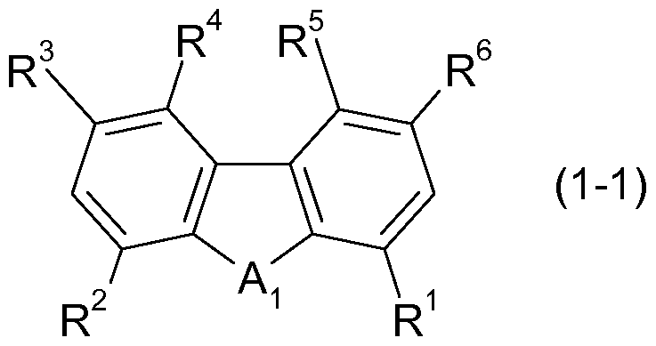


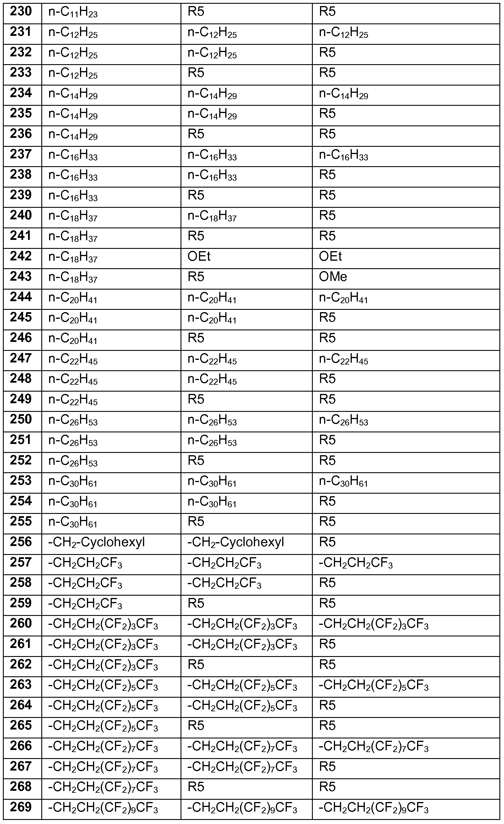


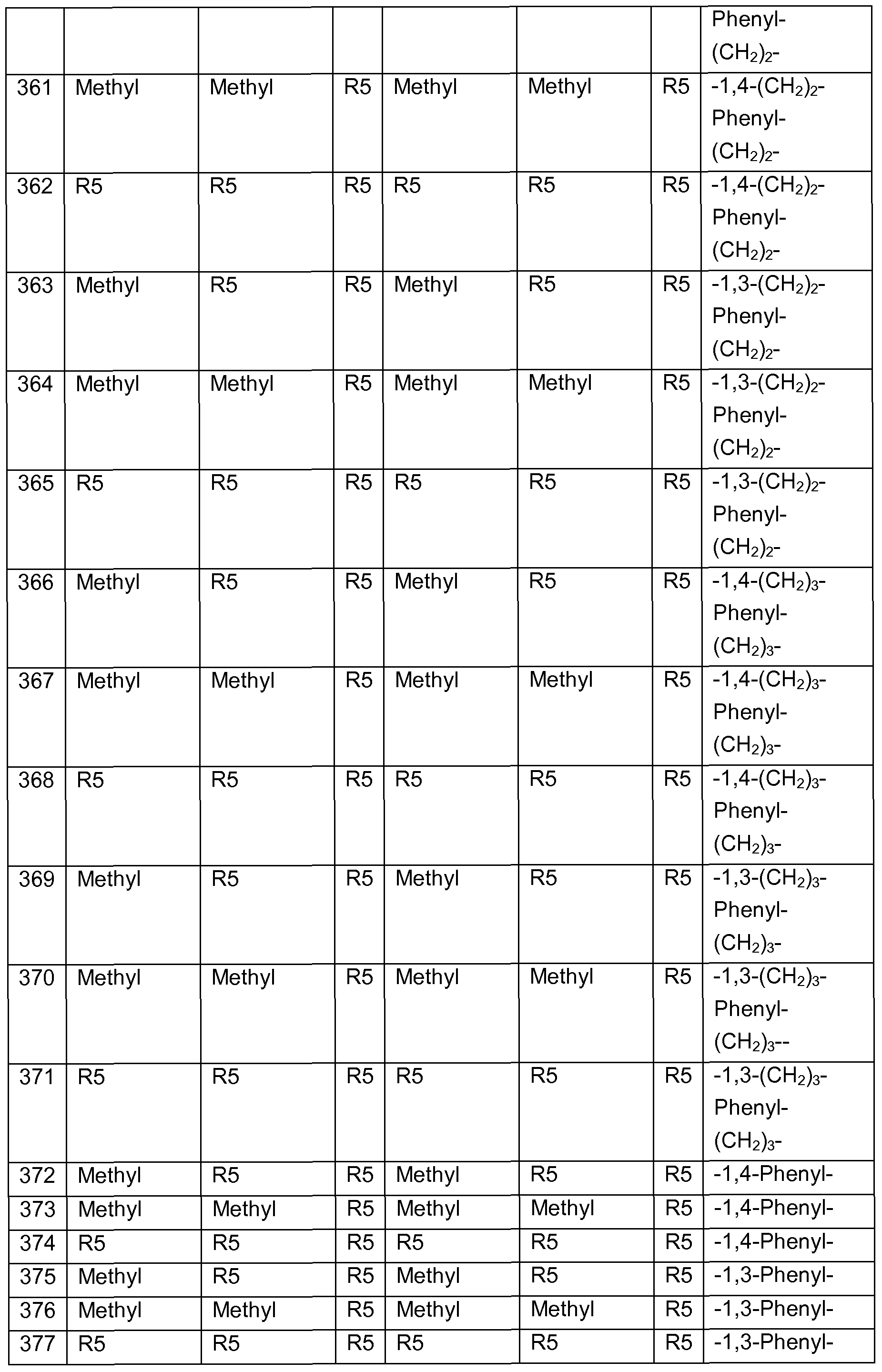
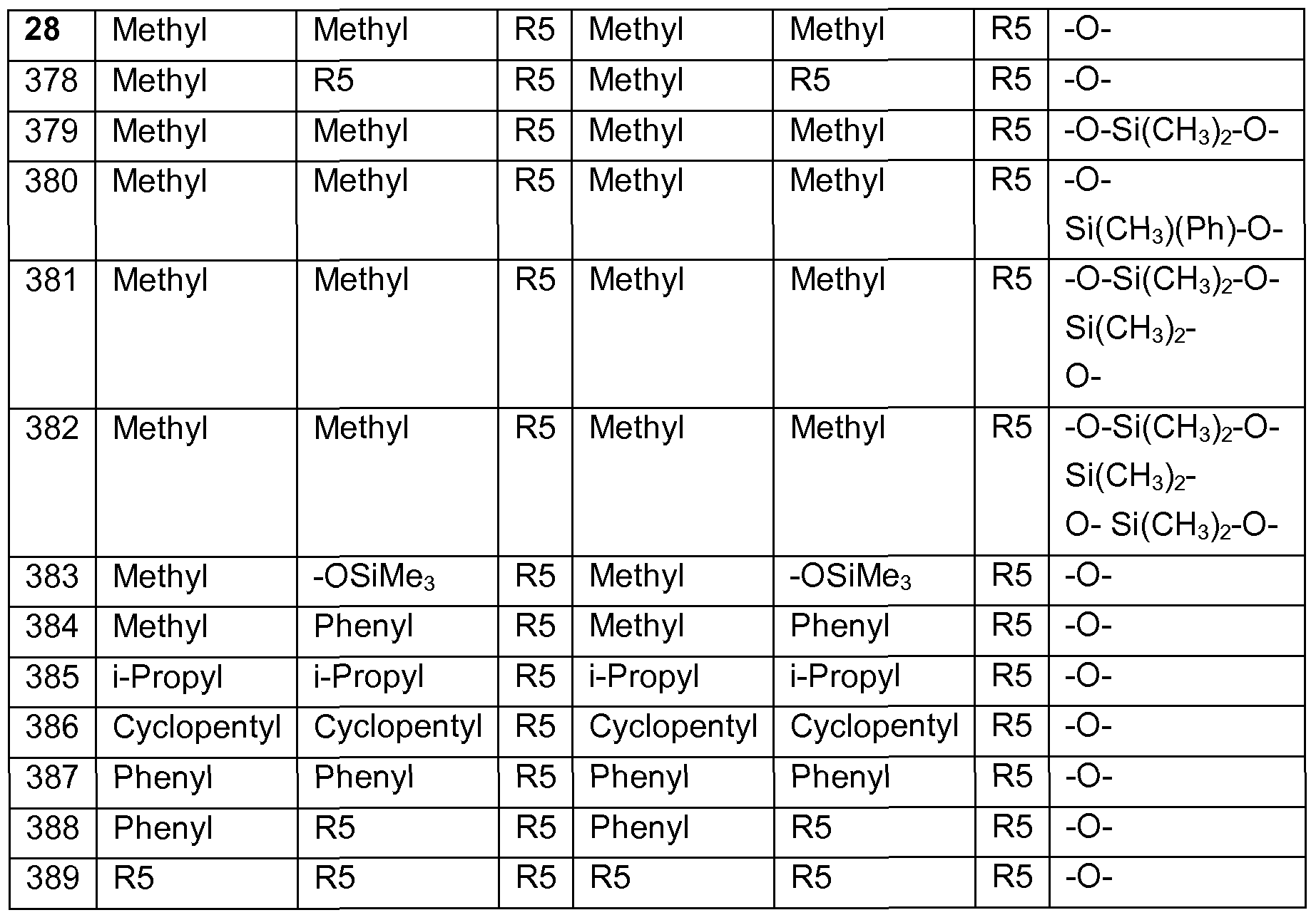


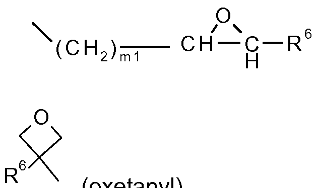


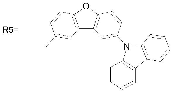


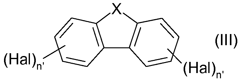

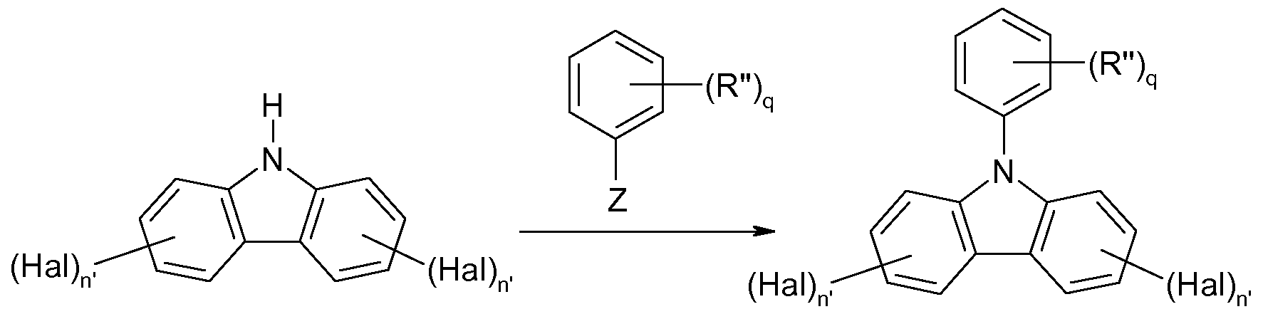


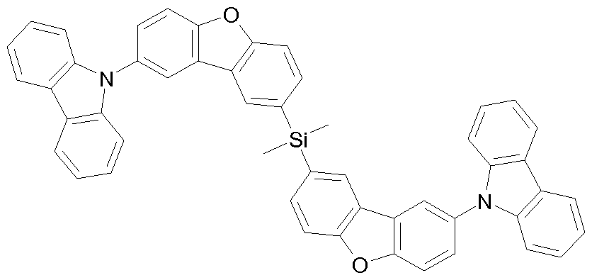


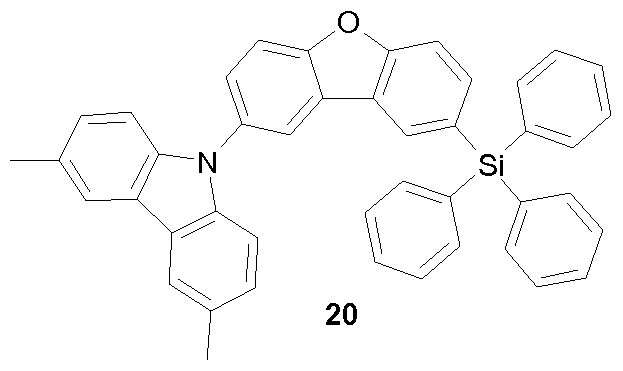


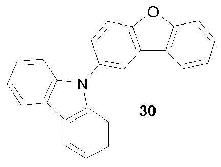


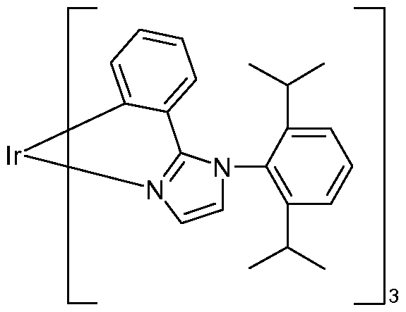


Claims


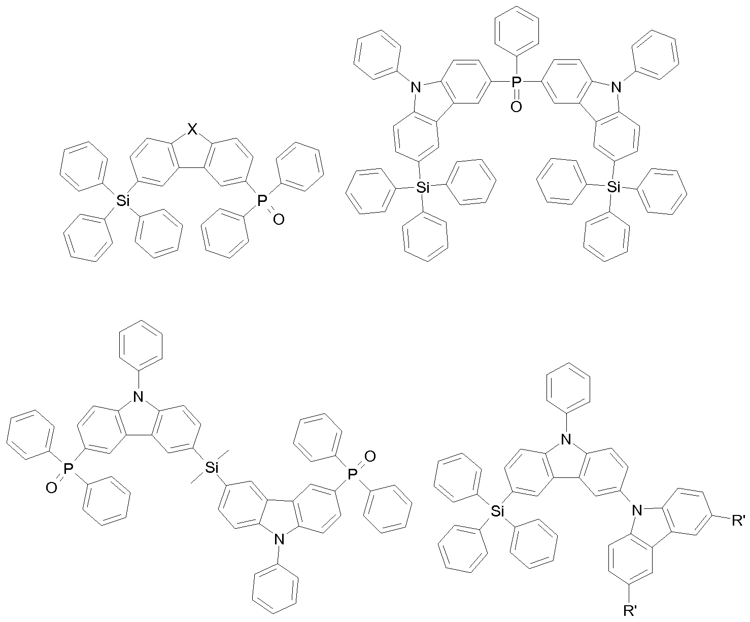


Priority Applications (5)
| Application Number | Priority Date | Filing Date | Title |
|---|---|---|---|
| EP09795397.0A EP2393819B9 (de) | 2009-01-07 | 2009-12-14 | Silyl- und heteroatom-substituierte verbindungen ausgewählt aus carbazolen, dibenzofuranen, dibenzothiophenen und dibenzophospholen und ihre anwendung in der organischen elektronik |
| US13/143,651 US9458182B2 (en) | 2009-01-07 | 2009-12-14 | Silyl- and heteroatom-substituted compounds selected from carbazoles, dibenzofurans, dibenzothiophenes and dibenzophospholes, and use thereof in organic electronics |
| JP2011544828A JP5808252B2 (ja) | 2009-01-07 | 2009-12-14 | カルバゾール、ジベンゾフラン、ジベンゾチオフェンおよびジベンゾホスホールから選択されたシリル置換およびヘテロ原子置換された化合物および該化合物の有機エレクトロニクスへの使用 |
| KR1020117018426A KR101693903B1 (ko) | 2009-01-07 | 2009-12-14 | 카르바졸, 디벤조푸란, 디벤조티오펜 및 디펜조포스폴로부터 선택된 실릴 및 이종원자 치환된 화합물, 및 이의 유기 전자 장치에서의 용도 |
| CN200980157855.2A CN102341403B (zh) | 2009-01-07 | 2009-12-14 | 选自咔唑类、二苯并呋喃类、二苯并噻吩类和二苯并磷杂环戊二烯类的甲硅烷基和杂原子取代的化合物及其在有机电子器件中的应用 |
Applications Claiming Priority (4)
| Application Number | Priority Date | Filing Date | Title |
|---|---|---|---|
| EP09150181.7 | 2009-01-07 | ||
| EP09150176.7 | 2009-01-07 | ||
| EP09150176 | 2009-01-07 | ||
| EP09150181 | 2009-01-07 |
Publications (1)
| Publication Number | Publication Date |
|---|---|
| WO2010079051A1 true WO2010079051A1 (de) | 2010-07-15 |
Family
ID=41650490
Family Applications (1)
| Application Number | Title | Priority Date | Filing Date |
|---|---|---|---|
| PCT/EP2009/067120 WO2010079051A1 (de) | 2009-01-07 | 2009-12-14 | Silyl- und heteroatom-substituierte verbindungen ausgewählt aus carbazolen, dibenzofuranen, dibenzothiophenen und dibenzophospholen und ihre anwendung in der organischen elektronik |
Country Status (6)
| Country | Link |
|---|---|
| US (1) | US9458182B2 (de) |
| EP (1) | EP2393819B9 (de) |
| JP (1) | JP5808252B2 (de) |
| KR (1) | KR101693903B1 (de) |
| CN (1) | CN102341403B (de) |
| WO (1) | WO2010079051A1 (de) |
Cited By (87)
| Publication number | Priority date | Publication date | Assignee | Title |
|---|---|---|---|---|
| WO2011051404A1 (de) | 2009-10-28 | 2011-05-05 | Basf Se | Heteroleptische carben-komplexe und deren verwendung in der organischen elektronik |
| WO2011073149A1 (de) | 2009-12-14 | 2011-06-23 | Basf Se | Metallkomplexe, enthaltend diazabenzimidazolcarben-liganden und deren verwendung in oleds |
| CN102214801A (zh) * | 2011-06-09 | 2011-10-12 | 河北工业大学 | 双p型掺杂层的有机发光二极管 |
| WO2011157779A1 (en) | 2010-06-18 | 2011-12-22 | Basf Se | Organic electronic devices comprising a layer of a pyridine compound and a 8-hydroxyquinolinolato earth alkaline metal, or alkali metal complex |
| WO2011157790A1 (en) | 2010-06-18 | 2011-12-22 | Basf Se | Organic electronic devices comprising a layer of a dibenzofurane compound and a 8-hydroxyquinolinolato earth alkaline metal, or alkali metal complex |
| EP2436751A1 (de) * | 2009-05-27 | 2012-04-04 | Industry-Academic Cooperation Foundation, Dankook University | Carbazolbasierte phosphinoxidverbindung und organisches elektrolumineszenzelement damit |
| WO2012045710A1 (en) | 2010-10-07 | 2012-04-12 | Basf Se | Phenanthro[9,10-b]furans for electronic applications |
| CN102417519A (zh) * | 2011-12-31 | 2012-04-18 | 济南大学 | 一类用于发光材料的有机硅化合物及其制备方法 |
| CN102417518A (zh) * | 2011-12-31 | 2012-04-18 | 济南大学 | 一类用于发光材料的有机硅化合物及其制备方法 |
| WO2012080052A1 (en) | 2010-12-13 | 2012-06-21 | Basf Se | Bispyrimidines for electronic applications |
| DE102010056519A1 (de) * | 2010-12-27 | 2012-06-28 | Heliatek Gmbh | Optoelektronisches Bauelement mit dotierten Schichten |
| JP2012190843A (ja) * | 2011-03-08 | 2012-10-04 | Toshiba Corp | 有機電界発光素子、表示装置および照明装置 |
| WO2012130709A1 (en) | 2011-03-25 | 2012-10-04 | Basf Se | 4h-imidazo[1,2-a]imidazoles for electronic applications |
| WO2012172482A1 (en) * | 2011-06-14 | 2012-12-20 | Basf Se | Metal complexes comprising azabenzimidazole carbene ligands and the use thereof in oleds |
| JP2013016717A (ja) * | 2011-07-06 | 2013-01-24 | Konica Minolta Holdings Inc | 有機エレクトロルミネッセンス素子、表示装置及び照明装置 |
| US8362246B2 (en) | 2010-12-13 | 2013-01-29 | Basf Se | Bispyrimidines for electronic applications |
| JP2013028605A (ja) * | 2011-07-28 | 2013-02-07 | Universal Display Corp | 燐光oledのためのホスト物質 |
| WO2013038843A1 (ja) * | 2011-09-12 | 2013-03-21 | 新日鉄住金化学株式会社 | 有機電界発光素子 |
| JP2013063963A (ja) * | 2011-08-31 | 2013-04-11 | Semiconductor Energy Lab Co Ltd | 複素環化合物、発光素子、発光装置、電子機器、及び照明装置 |
| JP2013075890A (ja) * | 2011-09-14 | 2013-04-25 | Idemitsu Kosan Co Ltd | ヘテロ芳香族化合物及びそれを用いた有機エレクトロルミネッセンス素子 |
| CN103102364A (zh) * | 2011-11-14 | 2013-05-15 | 通用显示公司 | 三亚苯硅烷主体 |
| WO2013068376A1 (en) | 2011-11-10 | 2013-05-16 | Basf Se | 4h-imidazo[1,2-a]imidazoles for electronic applications |
| JP2013093432A (ja) * | 2011-10-26 | 2013-05-16 | Konica Minolta Holdings Inc | 有機エレクトロルミネッセンス素子用材料、有機エレクトロルミネッセンス素子、表示装置及び照明装置 |
| WO2013118507A1 (ja) * | 2012-02-10 | 2013-08-15 | 出光興産株式会社 | 有機エレクトロルミネッセンス素子用材料及びそれを用いた有機エレクトロルミネッセンス素子 |
| JP2013234182A (ja) * | 2012-05-04 | 2013-11-21 | Universal Display Corp | トリアリールシラン側鎖をもつ非対称ホスト |
| WO2014009317A1 (en) | 2012-07-10 | 2014-01-16 | Basf Se | Benzimidazo[1,2-a]benzimidazole derivatives for electronic applications |
| WO2014012972A1 (en) | 2012-07-19 | 2014-01-23 | Basf Se | Dinuclear metal complexes comprising carbene ligands and the use thereof in oleds |
| CN103596963A (zh) * | 2011-05-25 | 2014-02-19 | 环球展览公司 | 用于有机发光装置的主体材料 |
| US8691401B2 (en) | 2010-04-16 | 2014-04-08 | Basf Se | Bridged benzimidazole-carbene complexes and use thereof in OLEDS |
| US8716484B1 (en) | 2012-12-05 | 2014-05-06 | Universal Display Corporation | Hole transporting materials with twisted aryl groups |
| JP2014521593A (ja) * | 2011-05-05 | 2014-08-28 | メルク パテント ゲーエムベーハー | 電子デバイスのための化合物 |
| WO2014147134A1 (en) | 2013-03-20 | 2014-09-25 | Basf Se | Azabenzimidazole carbene complexes as efficiency booster in oleds |
| WO2014177518A1 (en) | 2013-04-29 | 2014-11-06 | Basf Se | Transition metal complexes with carbene ligands and the use thereof in oleds |
| US8889864B2 (en) | 2006-02-10 | 2014-11-18 | Universal Display Corporation | Metal complexes of cyclometallated imidazo[1,2-f]phenanthridine and diimidazo[1,2-a:1′,2′-c]quinazoline ligands and isoelectronic and benzannulated analogs thereof |
| WO2015000955A1 (en) | 2013-07-02 | 2015-01-08 | Basf Se | Monosubstituted diazabenzimidazole carbene metal complexes for use in organic light emitting diodes |
| WO2015063046A1 (en) | 2013-10-31 | 2015-05-07 | Basf Se | Azadibenzothiophenes for electronic applications |
| US9054344B2 (en) | 2010-01-20 | 2015-06-09 | Universal Display Corporation | Electroluminescent devices for lighting applications |
| US9067919B2 (en) | 2010-07-08 | 2015-06-30 | Basf Se | Use of dibenzofurans and dibenzothiophenes substituted by nitrogen-bonded five-membered heterocyclic rings in organic electronics |
| US9079872B2 (en) | 2010-10-07 | 2015-07-14 | Basf Se | Phenanthro[9, 10-B]furans for electronic applications |
| WO2015114102A1 (en) * | 2014-02-03 | 2015-08-06 | Basf Se | Silyl substituted azadibenzofurans and azadibenzothiophenes |
| US9142792B2 (en) | 2010-06-18 | 2015-09-22 | Basf Se | Organic electronic devices comprising a layer comprising at least one metal organic compound and at least one metal oxide |
| US9196860B2 (en) | 2012-12-04 | 2015-11-24 | Universal Display Corporation | Compounds for triplet-triplet annihilation upconversion |
| EP2977378A1 (de) * | 2014-07-23 | 2016-01-27 | Samsung Electronics Co., Ltd | Kondensierte cyclische verbindung und organische lichtemittierende vorrichtung damit |
| US9252363B2 (en) | 2012-10-04 | 2016-02-02 | Universal Display Corporation | Aryloxyalkylcarboxylate solvent compositions for inkjet printing of organic layers |
| WO2016016791A1 (en) | 2014-07-28 | 2016-02-04 | Idemitsu Kosan Co., Ltd (Ikc) | 2,9-functionalized benzimidazolo[1,2-a]benzimidazoles as hosts for organic light emitting diodes (oleds) |
| EP2982676A1 (de) | 2014-08-07 | 2016-02-10 | Idemitsu Kosan Co., Ltd. | Benzimidazo[2,1-b]benzoxazole für elektronische Anwendungen |
| EP2993215A1 (de) | 2014-09-04 | 2016-03-09 | Idemitsu Kosan Co., Ltd. | Azabenzimidazo[2,1-a]benzimidazole für elektronische Anwendungen |
| CN105470404A (zh) * | 2015-11-23 | 2016-04-06 | 北京大学 | 一种节能环保的有机发光元件 |
| US9315724B2 (en) | 2011-06-14 | 2016-04-19 | Basf Se | Metal complexes comprising azabenzimidazole carbene ligands and the use thereof in OLEDs |
| EP3015469A1 (de) | 2014-10-30 | 2016-05-04 | Idemitsu Kosan Co., Ltd. | 5-((benz)imidazol-2-yl)benzimidazo[1,2-a]benzimidazole für elektronische anwendungen |
| WO2016079667A1 (en) | 2014-11-17 | 2016-05-26 | Idemitsu Kosan Co., Ltd. | Indole derivatives for electronic applications |
| WO2016079169A1 (en) | 2014-11-18 | 2016-05-26 | Basf Se | Pt- or pd-carbene complexes for use in organic light emitting diodes |
| EP3034507A1 (de) | 2014-12-15 | 2016-06-22 | Idemitsu Kosan Co., Ltd | 1-funktionalisierte Dibenzofurane und Dibenzothiophene für organische Leuchtdioden (OLEDS) |
| EP3034506A1 (de) | 2014-12-15 | 2016-06-22 | Idemitsu Kosan Co., Ltd | 4-funktionalisierte Carbazolderivate für elektronische Anwendungen |
| KR20160077488A (ko) * | 2014-12-23 | 2016-07-04 | 한화케미칼 주식회사 | 신규한 4족 전이금속 화합물 및 이의 용도 |
| EP3053918A1 (de) | 2015-02-06 | 2016-08-10 | Idemitsu Kosan Co., Ltd | 2-Carbazol substituierte Benzimidazole für elektronische Anwendungen |
| EP3054498A1 (de) | 2015-02-06 | 2016-08-10 | Idemitsu Kosan Co., Ltd. | Bisimidazodiazozine |
| EP3061759A1 (de) | 2015-02-24 | 2016-08-31 | Idemitsu Kosan Co., Ltd | Nitrilsubstituierte dibenzofurane |
| US9450198B2 (en) | 2014-04-15 | 2016-09-20 | Universal Display Corporation | Organic electroluminescent materials and devices |
| EP3070144A1 (de) | 2015-03-17 | 2016-09-21 | Idemitsu Kosan Co., Ltd. | Siebengliedrige ringverbindungen |
| EP3072943A1 (de) | 2015-03-26 | 2016-09-28 | Idemitsu Kosan Co., Ltd. | Dibenzofuran/carbazol-substituierte benzonitrile |
| EP3075737A1 (de) | 2015-03-31 | 2016-10-05 | Idemitsu Kosan Co., Ltd | Benzimidazolo[1,2-a]benzimidazol mit aryl- oder heteroarylnitrilgruppen für organische leuchtdioden |
| WO2016193243A1 (en) | 2015-06-03 | 2016-12-08 | Udc Ireland Limited | Highly efficient oled devices with very short decay times |
| EP3150606A1 (de) | 2015-10-01 | 2017-04-05 | Idemitsu Kosan Co., Ltd. | Benzimidazolo[1,2-a]benzimidazole mit benzofuran- oder benzothiophen- gruppen für organische licht emittierende dioden. |
| EP3150604A1 (de) | 2015-10-01 | 2017-04-05 | Idemitsu Kosan Co., Ltd. | Benzimidazolo[1,2-a]benzimidazol mit benzimidazolo[1,2-a]benzimidazolylgruppen, carbazolylgruppen, benzofurangruppen oder benzothiophengruppen für organische leuchtdioden |
| WO2017056055A1 (en) | 2015-10-01 | 2017-04-06 | Idemitsu Kosan Co., Ltd. | Benzimidazolo[1,2-a]benzimidazole carrying triazine groups for organic light emitting diodes |
| WO2017056053A1 (en) | 2015-10-01 | 2017-04-06 | Idemitsu Kosan Co., Ltd. | Benzimidazolo[1,2-a]benzimidazole carrying benzimidazolo[1,2-a]benzimidazolyl groups, carbazolyl groups, benzofurane groups or benzothiophene groups for organic light emitting diodes |
| US9653691B2 (en) | 2012-12-12 | 2017-05-16 | Universal Display Corporation | Phosphorescence-sensitizing fluorescence material system |
| WO2017093958A1 (en) | 2015-12-04 | 2017-06-08 | Idemitsu Kosan Co., Ltd. | Benzimidazolo[1,2-a]benzimidazole derivatives for organic light emitting diodes |
| EP3184534A1 (de) | 2015-12-21 | 2017-06-28 | UDC Ireland Limited | Übergangsmetallkomplexe mit dreibeinigen liganden und verwendung davon in oleds |
| US9761814B2 (en) | 2014-11-18 | 2017-09-12 | Universal Display Corporation | Organic light-emitting materials and devices |
| WO2017178864A1 (en) | 2016-04-12 | 2017-10-19 | Idemitsu Kosan Co., Ltd. | Seven-membered ring compounds |
| US9806270B2 (en) | 2011-03-25 | 2017-10-31 | Udc Ireland Limited | 4H-imidazo[1,2-a]imidazoles for electronic applications |
| EP3239161A1 (de) | 2013-07-31 | 2017-11-01 | UDC Ireland Limited | Lumineszente diazabenzimidazol-carben-metall-komplexe |
| US9812653B2 (en) | 2013-11-28 | 2017-11-07 | Samsung Electronics Co., Ltd. | Carbazole compound and organic light-emitting device including the same |
| US9862739B2 (en) | 2014-03-31 | 2018-01-09 | Udc Ireland Limited | Metal complexes, comprising carbene ligands having an O-substituted non-cyclometalated aryl group and their use in organic light emitting diodes |
| US9876173B2 (en) | 2013-12-09 | 2018-01-23 | Universal Display Corporation | Organic electroluminescent materials and devices |
| EP3318566A1 (de) | 2012-09-20 | 2018-05-09 | UDC Ireland Limited | Azadibenzofurane für elektronische anwendungen |
| EP3466957A1 (de) | 2014-08-08 | 2019-04-10 | UDC Ireland Limited | Oled enthaltend einen elektrolumineszenten imidazo-chinoxalin-carben-metallkomplexe |
| US10347851B2 (en) | 2013-12-20 | 2019-07-09 | Udc Ireland Limited | Highly efficient OLED devices with very short decay times |
| DE102013200085B4 (de) | 2012-01-06 | 2020-06-18 | Universal Display Corporation | Hocheffiziente phosphoreszierende Materialien |
| KR20210092336A (ko) * | 2012-02-14 | 2021-07-23 | 메르크 파텐트 게엠베하 | 유기 전계발광 소자용 스피로비플루오렌 화합물 |
| US20220135601A1 (en) * | 2020-11-05 | 2022-05-05 | Samsung Display Co., Ltd. | Heterocyclic compound, light-emitting device including the heterocyclic compound, and electronic apparatus including the light-emitting device |
| DE102013214144B4 (de) | 2012-07-19 | 2023-02-16 | Universal Display Corp. | Diarylamino-substituierte Metallkomplexe |
| US11706972B2 (en) | 2015-09-08 | 2023-07-18 | Universal Display Corporation | Organic electroluminescent materials and devices |
| DE102013003605B4 (de) | 2012-03-15 | 2023-08-17 | Universal Display Corporation | Sekundäre Lochtransportschicht mit Tricarbazolverbindungen |
| US11844266B2 (en) | 2019-01-31 | 2023-12-12 | Samsung Electronics Co., Ltd. | Organometallic compound and organic light-emitting device including the same |
Families Citing this family (19)
| Publication number | Priority date | Publication date | Assignee | Title |
|---|---|---|---|---|
| JP5914462B2 (ja) | 2011-04-05 | 2016-05-11 | 株式会社Adeka | 新規化合物及び光電変換素子 |
| US9419231B2 (en) | 2012-07-25 | 2016-08-16 | Idemitsu Kosan Co., Ltd. | Organic electroluminescence device |
| JP6189296B2 (ja) * | 2012-07-25 | 2017-08-30 | 出光興産株式会社 | 有機エレクトロルミネッセンス素子 |
| KR102044134B1 (ko) * | 2012-12-03 | 2019-12-02 | 엘지디스플레이 주식회사 | 인광 화합물 및 이를 이용한 유기발광다이오드소자 |
| CN103881067B (zh) * | 2012-12-24 | 2016-06-01 | 海洋王照明科技股份有限公司 | 一种聚合物蓝光主体材料及其制备方法与应用 |
| TWI686971B (zh) * | 2013-08-09 | 2020-03-01 | 日商半導體能源研究所股份有限公司 | 發光元件、顯示模組、照明模組、發光裝置、顯示裝置、電子裝置、及照明裝置 |
| CN104393181B (zh) * | 2014-10-30 | 2017-02-01 | 中国科学院长春应用化学研究所 | 一种红色有机电致发光器件及其制备方法 |
| GB2535476A (en) * | 2015-02-16 | 2016-08-24 | Cambridge Display Tech Ltd | Compound, composition and organic light-emitting device |
| US9780316B2 (en) * | 2015-03-16 | 2017-10-03 | Universal Display Corporation | Organic electroluminescent materials and devices |
| US10153445B2 (en) * | 2016-11-21 | 2018-12-11 | Universal Display Corporation | Organic electroluminescent materials and devices |
| US10777754B2 (en) * | 2017-04-11 | 2020-09-15 | Universal Display Corporation | Organic electroluminescent materials and devices |
| KR102458681B1 (ko) * | 2017-04-14 | 2022-10-26 | 삼성디스플레이 주식회사 | 헤테로시클릭 화합물 및 이를 포함한 유기 발광 소자 |
| KR102449219B1 (ko) | 2017-05-17 | 2022-09-30 | 삼성디스플레이 주식회사 | 유기 발광 소자 |
| US20190280215A1 (en) * | 2018-03-08 | 2019-09-12 | Samsung Display Co., Ltd. | Organic light-emitting device |
| CN110078757B (zh) * | 2019-05-24 | 2021-07-02 | 南京邮电大学 | 一种芳基硅有机光电材料及其制备方法与应用 |
| CN112321567B (zh) * | 2020-10-22 | 2023-01-13 | 安徽科技学院 | 一种多刺激响应型材料及其制备方法和应用 |
| CN113105440B (zh) * | 2021-04-15 | 2022-10-04 | 吉林奥来德光电材料股份有限公司 | 一种有机电致发光化合物及其制备方法和应用 |
| CN113512055A (zh) * | 2021-07-10 | 2021-10-19 | 浙江华显光电科技有限公司 | 硅烷衍生物,发光器件材料及发光器件 |
| CN114318375B (zh) * | 2021-07-20 | 2023-04-11 | 中钢集团南京新材料研究院有限公司 | 一种吲哚并[2,3-a]咔唑及其制备方法 |
Citations (2)
| Publication number | Priority date | Publication date | Assignee | Title |
|---|---|---|---|---|
| US20070224446A1 (en) * | 2006-03-24 | 2007-09-27 | Idemitsu Kosan Co., Ltd. | Material for organic electroluminescence device and organic electroluminescence device using the same |
| US20070262704A1 (en) * | 2006-05-15 | 2007-11-15 | Ken-Tsung Wong | Carbazole-based Compounds and Their Application |
Family Cites Families (11)
| Publication number | Priority date | Publication date | Assignee | Title |
|---|---|---|---|---|
| JPH05323634A (ja) * | 1992-05-26 | 1993-12-07 | Konica Corp | 電子写真感光体 |
| JP2004200141A (ja) * | 2002-10-24 | 2004-07-15 | Toyota Industries Corp | 有機el素子 |
| WO2005033090A1 (ja) * | 2003-10-06 | 2005-04-14 | Sumitomo Chemical Company, Limited | 芳香族化合物 |
| WO2005113704A2 (en) | 2004-05-18 | 2005-12-01 | The University Of Southern California | Luminescent compounds with carbene ligands |
| DE102005019880A1 (de) * | 2005-04-28 | 2006-11-09 | Basf Ag | Synthese von phenylsubstituierten Polyfluoranthenen und ihre Verwendung |
| JP4797440B2 (ja) * | 2005-05-19 | 2011-10-19 | 住友化学株式会社 | 芳香族化合物の製造方法 |
| EP2082447B1 (de) * | 2006-09-21 | 2018-10-24 | UDC Ireland Limited | Oled-anzeige mit verlängerter lebensdauer |
| KR100846590B1 (ko) | 2006-11-08 | 2008-07-16 | 삼성에스디아이 주식회사 | 실란일아민계 화합물, 이의 제조 방법 및 이를 포함한유기막을 구비한 유기 발광 소자 |
| KR100822212B1 (ko) | 2007-01-15 | 2008-04-16 | 삼성에스디아이 주식회사 | 실란일아민계 화합물 및 이를 포함한 유기막을 구비한 유기발광 소자 |
| JP5804703B2 (ja) | 2007-07-05 | 2015-11-04 | ビーエーエスエフ ソシエタス・ヨーロピアBasf Se | ジシリルカルバゾール、ジシリルジベンゾフラン、ジシリルジベンゾチオフェン、ジシリルジベンゾホスホール、ジシリルジベンゾチオフェンs−オキシドおよびジシリルジベンゾチオフェンs,s−ジオキシドから選択される少なくとも1つのジシリル化合物を含む有機発光ダイオード |
| US8373159B2 (en) | 2007-07-05 | 2013-02-12 | Basf Se | Organic light-emitting diodes comprising carbene-transition metal complex emitter, and at least one compound selected from disilylcarbazoles, disilyldibenzofurans, disilyldibenzothiophenes, disilyldibenzophospholes, disilyldibenzothiophene s-oxides and disilyldibe |
-
2009
- 2009-12-14 JP JP2011544828A patent/JP5808252B2/ja active Active
- 2009-12-14 WO PCT/EP2009/067120 patent/WO2010079051A1/de active Application Filing
- 2009-12-14 CN CN200980157855.2A patent/CN102341403B/zh active Active
- 2009-12-14 US US13/143,651 patent/US9458182B2/en active Active
- 2009-12-14 EP EP09795397.0A patent/EP2393819B9/de active Active
- 2009-12-14 KR KR1020117018426A patent/KR101693903B1/ko active IP Right Grant
Patent Citations (2)
| Publication number | Priority date | Publication date | Assignee | Title |
|---|---|---|---|---|
| US20070224446A1 (en) * | 2006-03-24 | 2007-09-27 | Idemitsu Kosan Co., Ltd. | Material for organic electroluminescence device and organic electroluminescence device using the same |
| US20070262704A1 (en) * | 2006-05-15 | 2007-11-15 | Ken-Tsung Wong | Carbazole-based Compounds and Their Application |
Cited By (155)
| Publication number | Priority date | Publication date | Assignee | Title |
|---|---|---|---|---|
| US9281483B2 (en) | 2006-02-10 | 2016-03-08 | Universal Display Corporation | Organic electroluminescent materials and devices |
| US9065063B2 (en) | 2006-02-10 | 2015-06-23 | Universal Display Corporation | Metal complexes of cyclometallated imidazo[1,2-f]phenanthridine and diimidazo[1,2-a:1′,2′-c]quinazoline ligands and isoelectronic and benzannulated analogs thereof |
| US9548462B2 (en) | 2006-02-10 | 2017-01-17 | Universal Display Corporation | Organic electroluminescent materials and devices |
| US8889864B2 (en) | 2006-02-10 | 2014-11-18 | Universal Display Corporation | Metal complexes of cyclometallated imidazo[1,2-f]phenanthridine and diimidazo[1,2-a:1′,2′-c]quinazoline ligands and isoelectronic and benzannulated analogs thereof |
| EP2436751A4 (de) * | 2009-05-27 | 2013-04-10 | Univ Dankook Iacf | Carbazolbasierte phosphinoxidverbindung und organisches elektrolumineszenzelement damit |
| EP2436751A1 (de) * | 2009-05-27 | 2012-04-04 | Industry-Academic Cooperation Foundation, Dankook University | Carbazolbasierte phosphinoxidverbindung und organisches elektrolumineszenzelement damit |
| US11871654B2 (en) | 2009-10-28 | 2024-01-09 | Udc Ireland Limited | Heteroleptic carbene complexes and the use thereof in organic electronics |
| US11189806B2 (en) | 2009-10-28 | 2021-11-30 | Udc Ireland Limited | Heteroleptic carbene complexes and the use thereof in organic electronics |
| WO2011051404A1 (de) | 2009-10-28 | 2011-05-05 | Basf Se | Heteroleptische carben-komplexe und deren verwendung in der organischen elektronik |
| US11839140B2 (en) | 2009-12-14 | 2023-12-05 | Udc Ireland Limited | Metal complexes comprising diazabenzmidazolocarbene ligands and the use thereof in OLEDS |
| US10090476B2 (en) | 2009-12-14 | 2018-10-02 | Udc Ireland Limited | Metal complexes comprising diazabenzmidazolocarbene ligands and the use thereof in OLEDs |
| US10916716B2 (en) | 2009-12-14 | 2021-02-09 | Udc Ireland Limited | Metal complexes comprising diazabenzmidazolocarbene ligands and the use thereof in OLEDS |
| US9487548B2 (en) | 2009-12-14 | 2016-11-08 | Udc Ireland Limited | Metal complexes comprising diazabenzimidazolocarbene ligands and the use thereof in OLEDs |
| WO2011073149A1 (de) | 2009-12-14 | 2011-06-23 | Basf Se | Metallkomplexe, enthaltend diazabenzimidazolcarben-liganden und deren verwendung in oleds |
| US11444254B2 (en) | 2009-12-14 | 2022-09-13 | Udc Ireland Limited | Metal complexes comprising diazabenzmidazolocarbene ligands and the use thereof in OLEDs |
| US9054344B2 (en) | 2010-01-20 | 2015-06-09 | Universal Display Corporation | Electroluminescent devices for lighting applications |
| US8691401B2 (en) | 2010-04-16 | 2014-04-08 | Basf Se | Bridged benzimidazole-carbene complexes and use thereof in OLEDS |
| WO2011157779A1 (en) | 2010-06-18 | 2011-12-22 | Basf Se | Organic electronic devices comprising a layer of a pyridine compound and a 8-hydroxyquinolinolato earth alkaline metal, or alkali metal complex |
| US9142792B2 (en) | 2010-06-18 | 2015-09-22 | Basf Se | Organic electronic devices comprising a layer comprising at least one metal organic compound and at least one metal oxide |
| WO2011157790A1 (en) | 2010-06-18 | 2011-12-22 | Basf Se | Organic electronic devices comprising a layer of a dibenzofurane compound and a 8-hydroxyquinolinolato earth alkaline metal, or alkali metal complex |
| US9067919B2 (en) | 2010-07-08 | 2015-06-30 | Basf Se | Use of dibenzofurans and dibenzothiophenes substituted by nitrogen-bonded five-membered heterocyclic rings in organic electronics |
| US9079872B2 (en) | 2010-10-07 | 2015-07-14 | Basf Se | Phenanthro[9, 10-B]furans for electronic applications |
| WO2012045710A1 (en) | 2010-10-07 | 2012-04-12 | Basf Se | Phenanthro[9,10-b]furans for electronic applications |
| CN107266398A (zh) * | 2010-10-07 | 2017-10-20 | Udc 爱尔兰有限责任公司 | 用于电子应用的菲并[9,10‑b]呋喃 |
| WO2012080052A1 (en) | 2010-12-13 | 2012-06-21 | Basf Se | Bispyrimidines for electronic applications |
| US8362246B2 (en) | 2010-12-13 | 2013-01-29 | Basf Se | Bispyrimidines for electronic applications |
| DE102010056519A1 (de) * | 2010-12-27 | 2012-06-28 | Heliatek Gmbh | Optoelektronisches Bauelement mit dotierten Schichten |
| CN103314461B (zh) * | 2010-12-27 | 2016-02-17 | 赫里亚泰克有限责任公司 | 具有掺杂层的光电子元件 |
| CN103314461A (zh) * | 2010-12-27 | 2013-09-18 | 赫里亚泰克有限责任公司 | 具有掺杂层的光电子元件 |
| US8580403B2 (en) | 2011-03-08 | 2013-11-12 | Kabushiki Kaisha Toshiba | Organic light-emitting diode, display and illuminating device |
| JP2012190843A (ja) * | 2011-03-08 | 2012-10-04 | Toshiba Corp | 有機電界発光素子、表示装置および照明装置 |
| US9806270B2 (en) | 2011-03-25 | 2017-10-31 | Udc Ireland Limited | 4H-imidazo[1,2-a]imidazoles for electronic applications |
| EP3034508A1 (de) | 2011-03-25 | 2016-06-22 | Basf Se | 4h-imidazo[1,2-a]imidazole für elektronische anwendungen |
| US10431750B2 (en) | 2011-03-25 | 2019-10-01 | Udc Ireland Limited | 4H-imidazo[1,2-a]imidazoles for electronic applications |
| US11450812B2 (en) | 2011-03-25 | 2022-09-20 | Udc Ireland Limited | 4H-imidazo[1,2-a]imidazoles for electronic applications |
| WO2012130709A1 (en) | 2011-03-25 | 2012-10-04 | Basf Se | 4h-imidazo[1,2-a]imidazoles for electronic applications |
| EP3640252A1 (de) | 2011-03-25 | 2020-04-22 | UDC Ireland Limited | 4h-imidazo[1,2-a]imidazole für elektronische anwendungen |
| US10056549B2 (en) | 2011-05-05 | 2018-08-21 | Merck Patent Gmbh | Compounds for electronic devices |
| JP2014521593A (ja) * | 2011-05-05 | 2014-08-28 | メルク パテント ゲーエムベーハー | 電子デバイスのための化合物 |
| CN103596963A (zh) * | 2011-05-25 | 2014-02-19 | 环球展览公司 | 用于有机发光装置的主体材料 |
| CN106831846A (zh) * | 2011-05-25 | 2017-06-13 | 环球展览公司 | 用于有机发光装置的主体材料 |
| CN103596963B (zh) * | 2011-05-25 | 2016-12-21 | 环球展览公司 | 用于有机发光装置的主体材料 |
| CN102214801A (zh) * | 2011-06-09 | 2011-10-12 | 河北工业大学 | 双p型掺杂层的有机发光二极管 |
| EP3415521A1 (de) | 2011-06-14 | 2018-12-19 | UDC Ireland Limited | Metallkomplexe mit azabenzimidazolcarbenliganden und verwendung davon in oleds |
| WO2012172482A1 (en) * | 2011-06-14 | 2012-12-20 | Basf Se | Metal complexes comprising azabenzimidazole carbene ligands and the use thereof in oleds |
| CN107501330A (zh) * | 2011-06-14 | 2017-12-22 | Udc 爱尔兰有限责任公司 | 包含氮杂苯并咪唑碳烯配体的金属配合物及其在oled中的用途 |
| JP2018024696A (ja) * | 2011-06-14 | 2018-02-15 | ユー・ディー・シー アイルランド リミテッド | アザベンズイミダゾールカルベン配位子を有する金属錯体および有機発光ダイオードにおける当該金属錯体の使用 |
| JP2014523874A (ja) * | 2011-06-14 | 2014-09-18 | ビーエーエスエフ ソシエタス・ヨーロピア | アザベンズイミダゾールカルベン配位子を有する金属錯体および有機発光ダイオードにおける当該金属錯体の使用 |
| US9315724B2 (en) | 2011-06-14 | 2016-04-19 | Basf Se | Metal complexes comprising azabenzimidazole carbene ligands and the use thereof in OLEDs |
| JP2013016717A (ja) * | 2011-07-06 | 2013-01-24 | Konica Minolta Holdings Inc | 有機エレクトロルミネッセンス素子、表示装置及び照明装置 |
| KR101919621B1 (ko) * | 2011-07-28 | 2018-11-16 | 유니버셜 디스플레이 코포레이션 | 인광 oled용 호스트 물질 |
| EP3401974A1 (de) * | 2011-07-28 | 2018-11-14 | Universal Display Corporation | Hostmaterialien für phosphoreszierende oled |
| EP2551932A3 (de) * | 2011-07-28 | 2015-12-30 | Universal Display Corporation | Hostmaterialien für phosphoreszente OLED |
| JP2013028605A (ja) * | 2011-07-28 | 2013-02-07 | Universal Display Corp | 燐光oledのためのホスト物質 |
| KR20130018551A (ko) * | 2011-07-28 | 2013-02-25 | 유니버셜 디스플레이 코포레이션 | 인광 oled용 호스트 물질 |
| JP2019014737A (ja) * | 2011-07-28 | 2019-01-31 | ユニバーサル ディスプレイ コーポレイション | 燐光oledのためのホスト物質 |
| TWI555822B (zh) * | 2011-07-28 | 2016-11-01 | 環球展覽公司 | 用於磷光有機發光裝置之主體材料 |
| JP2017008107A (ja) * | 2011-07-28 | 2017-01-12 | ユニバーサル ディスプレイ コーポレイション | 燐光oledのためのホスト物質 |
| CN103122007A (zh) * | 2011-07-28 | 2013-05-29 | 通用显示公司 | 用作磷光材料的主体材料 |
| JP2013063963A (ja) * | 2011-08-31 | 2013-04-11 | Semiconductor Energy Lab Co Ltd | 複素環化合物、発光素子、発光装置、電子機器、及び照明装置 |
| JP2017057210A (ja) * | 2011-08-31 | 2017-03-23 | 株式会社半導体エネルギー研究所 | 複素環化合物 |
| US9142785B2 (en) | 2011-09-12 | 2015-09-22 | Nippon Steel & Sumikin Chemical Co., Ltd. | Organic electroluminescent element |
| WO2013038843A1 (ja) * | 2011-09-12 | 2013-03-21 | 新日鉄住金化学株式会社 | 有機電界発光素子 |
| TWI559592B (zh) * | 2011-09-12 | 2016-11-21 | Nippon Steel & Sumikin Chem Co | Organic electroluminescent elements |
| CN103907217A (zh) * | 2011-09-12 | 2014-07-02 | 新日铁住金化学株式会社 | 有机电致发光元件 |
| JP2013075890A (ja) * | 2011-09-14 | 2013-04-25 | Idemitsu Kosan Co Ltd | ヘテロ芳香族化合物及びそれを用いた有機エレクトロルミネッセンス素子 |
| JP2013093432A (ja) * | 2011-10-26 | 2013-05-16 | Konica Minolta Holdings Inc | 有機エレクトロルミネッセンス素子用材料、有機エレクトロルミネッセンス素子、表示装置及び照明装置 |
| WO2013068376A1 (en) | 2011-11-10 | 2013-05-16 | Basf Se | 4h-imidazo[1,2-a]imidazoles for electronic applications |
| US9502664B2 (en) | 2011-11-10 | 2016-11-22 | Udc Ireland Limited | 4H-imidazo[1,2-a]imidazoles for electronic applications |
| CN103102364A (zh) * | 2011-11-14 | 2013-05-15 | 通用显示公司 | 三亚苯硅烷主体 |
| JP2013103937A (ja) * | 2011-11-14 | 2013-05-30 | Universal Display Corp | トリフェニレンシランホスト |
| CN103102364B (zh) * | 2011-11-14 | 2017-03-01 | 通用显示公司 | 三亚苯硅烷主体 |
| TWI577689B (zh) * | 2011-11-14 | 2017-04-11 | 環球展覽公司 | 聯伸三苯矽烷主體 |
| CN102417518A (zh) * | 2011-12-31 | 2012-04-18 | 济南大学 | 一类用于发光材料的有机硅化合物及其制备方法 |
| CN102417519A (zh) * | 2011-12-31 | 2012-04-18 | 济南大学 | 一类用于发光材料的有机硅化合物及其制备方法 |
| DE102013200085B4 (de) | 2012-01-06 | 2020-06-18 | Universal Display Corporation | Hocheffiziente phosphoreszierende Materialien |
| WO2013118507A1 (ja) * | 2012-02-10 | 2013-08-15 | 出光興産株式会社 | 有機エレクトロルミネッセンス素子用材料及びそれを用いた有機エレクトロルミネッセンス素子 |
| KR20210092336A (ko) * | 2012-02-14 | 2021-07-23 | 메르크 파텐트 게엠베하 | 유기 전계발광 소자용 스피로비플루오렌 화합물 |
| KR102357439B1 (ko) | 2012-02-14 | 2022-02-08 | 메르크 파텐트 게엠베하 | 유기 전계발광 소자용 스피로비플루오렌 화합물 |
| DE102013003605B4 (de) | 2012-03-15 | 2023-08-17 | Universal Display Corporation | Sekundäre Lochtransportschicht mit Tricarbazolverbindungen |
| JP2013234182A (ja) * | 2012-05-04 | 2013-11-21 | Universal Display Corp | トリアリールシラン側鎖をもつ非対称ホスト |
| US10862051B2 (en) | 2012-07-10 | 2020-12-08 | Udc Ireland Limited | Benzimidazo[1,2-a]benzimidazole derivatives for electronic applications |
| EP3232485A1 (de) | 2012-07-10 | 2017-10-18 | UDC Ireland Limited | Benzimidazo[1,2-a]benzimidazol-derivate für elektronische anwendungen |
| US10243150B2 (en) | 2012-07-10 | 2019-03-26 | Udc Ireland Limited | Benzimidazo[1,2-a]benzimidazole derivatives for electronic applications |
| WO2014009317A1 (en) | 2012-07-10 | 2014-01-16 | Basf Se | Benzimidazo[1,2-a]benzimidazole derivatives for electronic applications |
| US11744152B2 (en) | 2012-07-10 | 2023-08-29 | Udc Ireland Limited | Benzimidazo[1,2-a]benzimidazole derivatives for electronic applications |
| US9620724B2 (en) | 2012-07-10 | 2017-04-11 | Udc Ireland Limited | Benzimidazo[1,2-A]benzimidazole derivatives for electronic applications |
| DE102013214144B4 (de) | 2012-07-19 | 2023-02-16 | Universal Display Corp. | Diarylamino-substituierte Metallkomplexe |
| WO2014012972A1 (en) | 2012-07-19 | 2014-01-23 | Basf Se | Dinuclear metal complexes comprising carbene ligands and the use thereof in oleds |
| EP3133079A1 (de) | 2012-07-19 | 2017-02-22 | UDC Ireland Limited | Dinukleare metallkomplexe mit carbenliganden und verwendung davon in oleds |
| US9590196B2 (en) | 2012-07-19 | 2017-03-07 | Udc Ireland Limited | Dinuclear metal complexes comprising carbene ligands and the use thereof in OLEDs |
| EP3318566A1 (de) | 2012-09-20 | 2018-05-09 | UDC Ireland Limited | Azadibenzofurane für elektronische anwendungen |
| US10249827B2 (en) | 2012-09-20 | 2019-04-02 | Udc Ireland Limited | Azadibenzofurans for electronic applications |
| US9252363B2 (en) | 2012-10-04 | 2016-02-02 | Universal Display Corporation | Aryloxyalkylcarboxylate solvent compositions for inkjet printing of organic layers |
| US9196860B2 (en) | 2012-12-04 | 2015-11-24 | Universal Display Corporation | Compounds for triplet-triplet annihilation upconversion |
| US8716484B1 (en) | 2012-12-05 | 2014-05-06 | Universal Display Corporation | Hole transporting materials with twisted aryl groups |
| US9653691B2 (en) | 2012-12-12 | 2017-05-16 | Universal Display Corporation | Phosphorescence-sensitizing fluorescence material system |
| WO2014147134A1 (en) | 2013-03-20 | 2014-09-25 | Basf Se | Azabenzimidazole carbene complexes as efficiency booster in oleds |
| WO2014177518A1 (en) | 2013-04-29 | 2014-11-06 | Basf Se | Transition metal complexes with carbene ligands and the use thereof in oleds |
| EP3608329A1 (de) | 2013-07-02 | 2020-02-12 | UDC Ireland Limited | Monosubstituierte diazabenzimidazolcarben-metall-komplexe zur verwendung in organischen leuchtdioden |
| WO2015000955A1 (en) | 2013-07-02 | 2015-01-08 | Basf Se | Monosubstituted diazabenzimidazole carbene metal complexes for use in organic light emitting diodes |
| EP3266789A1 (de) | 2013-07-02 | 2018-01-10 | UDC Ireland Limited | Monosubstituierte diazabenzimidazolcarben-metall-komplexe zur verwendung in organischen leuchtdioden |
| US11605790B2 (en) | 2013-07-02 | 2023-03-14 | Udc Ireland Limited | Monosubstituted diazabenzimidazole carbene metal complexes for use in organic light emitting diodes |
| EP3239161A1 (de) | 2013-07-31 | 2017-11-01 | UDC Ireland Limited | Lumineszente diazabenzimidazol-carben-metall-komplexe |
| WO2015063046A1 (en) | 2013-10-31 | 2015-05-07 | Basf Se | Azadibenzothiophenes for electronic applications |
| US9812653B2 (en) | 2013-11-28 | 2017-11-07 | Samsung Electronics Co., Ltd. | Carbazole compound and organic light-emitting device including the same |
| US9876173B2 (en) | 2013-12-09 | 2018-01-23 | Universal Display Corporation | Organic electroluminescent materials and devices |
| US11765967B2 (en) | 2013-12-20 | 2023-09-19 | Udc Ireland Limited | Highly efficient OLED devices with very short decay times |
| US11075346B2 (en) | 2013-12-20 | 2021-07-27 | Udc Ireland Limited | Highly efficient OLED devices with very short decay times |
| US10347851B2 (en) | 2013-12-20 | 2019-07-09 | Udc Ireland Limited | Highly efficient OLED devices with very short decay times |
| EP3916822A1 (de) | 2013-12-20 | 2021-12-01 | UDC Ireland Limited | Hocheffiziente oled-vorrichtungen mit sehr kurzer abklingzeit |
| WO2015114102A1 (en) * | 2014-02-03 | 2015-08-06 | Basf Se | Silyl substituted azadibenzofurans and azadibenzothiophenes |
| US10118939B2 (en) | 2014-03-31 | 2018-11-06 | Udc Ireland Limited | Metal complexes, comprising carbene ligands having an o-substituted non-cyclometalated aryl group and their use in organic light emitting diodes |
| US9862739B2 (en) | 2014-03-31 | 2018-01-09 | Udc Ireland Limited | Metal complexes, comprising carbene ligands having an O-substituted non-cyclometalated aryl group and their use in organic light emitting diodes |
| US10370396B2 (en) | 2014-03-31 | 2019-08-06 | Udc Ireland Limited | Metal complexes, comprising carbene ligands having an O-substituted non-cyclometallated aryl group and their use in organic light emitting diodes |
| US9450198B2 (en) | 2014-04-15 | 2016-09-20 | Universal Display Corporation | Organic electroluminescent materials and devices |
| EP2977378A1 (de) * | 2014-07-23 | 2016-01-27 | Samsung Electronics Co., Ltd | Kondensierte cyclische verbindung und organische lichtemittierende vorrichtung damit |
| WO2016016791A1 (en) | 2014-07-28 | 2016-02-04 | Idemitsu Kosan Co., Ltd (Ikc) | 2,9-functionalized benzimidazolo[1,2-a]benzimidazoles as hosts for organic light emitting diodes (oleds) |
| EP2982676A1 (de) | 2014-08-07 | 2016-02-10 | Idemitsu Kosan Co., Ltd. | Benzimidazo[2,1-b]benzoxazole für elektronische Anwendungen |
| EP3466957A1 (de) | 2014-08-08 | 2019-04-10 | UDC Ireland Limited | Oled enthaltend einen elektrolumineszenten imidazo-chinoxalin-carben-metallkomplexe |
| EP2993215A1 (de) | 2014-09-04 | 2016-03-09 | Idemitsu Kosan Co., Ltd. | Azabenzimidazo[2,1-a]benzimidazole für elektronische Anwendungen |
| WO2016067261A1 (en) | 2014-10-30 | 2016-05-06 | Idemitsu Kosan Co., Ltd. | 5-((benz)imidazol-2-yl)benzimidazo[1,2-a]benzimidazoles for electronic applications |
| EP3015469A1 (de) | 2014-10-30 | 2016-05-04 | Idemitsu Kosan Co., Ltd. | 5-((benz)imidazol-2-yl)benzimidazo[1,2-a]benzimidazole für elektronische anwendungen |
| WO2016079667A1 (en) | 2014-11-17 | 2016-05-26 | Idemitsu Kosan Co., Ltd. | Indole derivatives for electronic applications |
| WO2016079169A1 (en) | 2014-11-18 | 2016-05-26 | Basf Se | Pt- or pd-carbene complexes for use in organic light emitting diodes |
| US9761814B2 (en) | 2014-11-18 | 2017-09-12 | Universal Display Corporation | Organic light-emitting materials and devices |
| EP3034506A1 (de) | 2014-12-15 | 2016-06-22 | Idemitsu Kosan Co., Ltd | 4-funktionalisierte Carbazolderivate für elektronische Anwendungen |
| EP3034507A1 (de) | 2014-12-15 | 2016-06-22 | Idemitsu Kosan Co., Ltd | 1-funktionalisierte Dibenzofurane und Dibenzothiophene für organische Leuchtdioden (OLEDS) |
| WO2016097983A1 (en) | 2014-12-15 | 2016-06-23 | Idemitsu Kosan Co., Ltd. | 1-functionalized dibenzofurans and dibenzothiophenes for organic light emitting diodes (oleds) |
| KR20160077488A (ko) * | 2014-12-23 | 2016-07-04 | 한화케미칼 주식회사 | 신규한 4족 전이금속 화합물 및 이의 용도 |
| US10364302B2 (en) | 2014-12-23 | 2019-07-30 | Hanwha Chemical Corporation | Group 4 transition metal compound and use thereof |
| KR101895650B1 (ko) | 2014-12-23 | 2018-09-06 | 한화케미칼 주식회사 | 신규한 4족 전이금속 화합물 및 이의 용도 |
| EP3054498A1 (de) | 2015-02-06 | 2016-08-10 | Idemitsu Kosan Co., Ltd. | Bisimidazodiazozine |
| WO2016125110A1 (en) | 2015-02-06 | 2016-08-11 | Idemitsu Kosan Co., Ltd. | Bisimidazolodiazocines |
| EP3053918A1 (de) | 2015-02-06 | 2016-08-10 | Idemitsu Kosan Co., Ltd | 2-Carbazol substituierte Benzimidazole für elektronische Anwendungen |
| EP3061759A1 (de) | 2015-02-24 | 2016-08-31 | Idemitsu Kosan Co., Ltd | Nitrilsubstituierte dibenzofurane |
| EP3070144A1 (de) | 2015-03-17 | 2016-09-21 | Idemitsu Kosan Co., Ltd. | Siebengliedrige ringverbindungen |
| EP3072943A1 (de) | 2015-03-26 | 2016-09-28 | Idemitsu Kosan Co., Ltd. | Dibenzofuran/carbazol-substituierte benzonitrile |
| EP3075737A1 (de) | 2015-03-31 | 2016-10-05 | Idemitsu Kosan Co., Ltd | Benzimidazolo[1,2-a]benzimidazol mit aryl- oder heteroarylnitrilgruppen für organische leuchtdioden |
| WO2016157113A1 (en) | 2015-03-31 | 2016-10-06 | Idemitsu Kosan Co., Ltd. | Benzimidazolo[1,2-a]benzimidazole carrying aryl- or heteroarylnitril groups for organic light emitting diodes |
| WO2016193243A1 (en) | 2015-06-03 | 2016-12-08 | Udc Ireland Limited | Highly efficient oled devices with very short decay times |
| EP4060757A1 (de) | 2015-06-03 | 2022-09-21 | UDC Ireland Limited | Hocheffiziente oled-vorrichtungen mit sehr kurzer abklingzeit |
| US11706972B2 (en) | 2015-09-08 | 2023-07-18 | Universal Display Corporation | Organic electroluminescent materials and devices |
| EP3150606A1 (de) | 2015-10-01 | 2017-04-05 | Idemitsu Kosan Co., Ltd. | Benzimidazolo[1,2-a]benzimidazole mit benzofuran- oder benzothiophen- gruppen für organische licht emittierende dioden. |
| WO2017056053A1 (en) | 2015-10-01 | 2017-04-06 | Idemitsu Kosan Co., Ltd. | Benzimidazolo[1,2-a]benzimidazole carrying benzimidazolo[1,2-a]benzimidazolyl groups, carbazolyl groups, benzofurane groups or benzothiophene groups for organic light emitting diodes |
| WO2017056052A1 (en) | 2015-10-01 | 2017-04-06 | Idemitsu Kosan Co., Ltd. | Benzimidazolo[1,2-a]benzimidazole carrying benzimidazolo[1,2-a]benzimidazolyl groups, carbazolyl groups, benzofurane groups or benzothiophene groups for organic light emitting diodes |
| WO2017056055A1 (en) | 2015-10-01 | 2017-04-06 | Idemitsu Kosan Co., Ltd. | Benzimidazolo[1,2-a]benzimidazole carrying triazine groups for organic light emitting diodes |
| EP3150604A1 (de) | 2015-10-01 | 2017-04-05 | Idemitsu Kosan Co., Ltd. | Benzimidazolo[1,2-a]benzimidazol mit benzimidazolo[1,2-a]benzimidazolylgruppen, carbazolylgruppen, benzofurangruppen oder benzothiophengruppen für organische leuchtdioden |
| CN105470404A (zh) * | 2015-11-23 | 2016-04-06 | 北京大学 | 一种节能环保的有机发光元件 |
| WO2017093958A1 (en) | 2015-12-04 | 2017-06-08 | Idemitsu Kosan Co., Ltd. | Benzimidazolo[1,2-a]benzimidazole derivatives for organic light emitting diodes |
| EP3184534A1 (de) | 2015-12-21 | 2017-06-28 | UDC Ireland Limited | Übergangsmetallkomplexe mit dreibeinigen liganden und verwendung davon in oleds |
| US10490754B2 (en) | 2015-12-21 | 2019-11-26 | Udc Ireland Limited | Transition metal complexes with tripodal ligands and the use thereof in OLEDs |
| WO2017178864A1 (en) | 2016-04-12 | 2017-10-19 | Idemitsu Kosan Co., Ltd. | Seven-membered ring compounds |
| US11844266B2 (en) | 2019-01-31 | 2023-12-12 | Samsung Electronics Co., Ltd. | Organometallic compound and organic light-emitting device including the same |
| US20220135601A1 (en) * | 2020-11-05 | 2022-05-05 | Samsung Display Co., Ltd. | Heterocyclic compound, light-emitting device including the heterocyclic compound, and electronic apparatus including the light-emitting device |
Also Published As
| Publication number | Publication date |
|---|---|
| JP5808252B2 (ja) | 2015-11-10 |
| EP2393819B9 (de) | 2017-12-27 |
| US9458182B2 (en) | 2016-10-04 |
| KR20120057556A (ko) | 2012-06-05 |
| CN102341403B (zh) | 2014-12-03 |
| EP2393819B1 (de) | 2017-01-25 |
| CN102341403A (zh) | 2012-02-01 |
| EP2393819A1 (de) | 2011-12-14 |
| KR101693903B1 (ko) | 2017-01-06 |
| JP2012514618A (ja) | 2012-06-28 |
| US20120012821A1 (en) | 2012-01-19 |
Similar Documents
| Publication | Publication Date | Title |
|---|---|---|
| EP2393819B9 (de) | Silyl- und heteroatom-substituierte verbindungen ausgewählt aus carbazolen, dibenzofuranen, dibenzothiophenen und dibenzophospholen und ihre anwendung in der organischen elektronik | |
| JP6763999B2 (ja) | イミダゾ[1,2−f]フェナントリジンイリジウム錯体に基づく高い効率を有する青色発光体 | |
| EP2165377B1 (de) | Organische leuchtdioden enthaltend carben-übergangsmetall-komplex-emitter und mindestens eine verbindung ausgewählt aus disilylcarbazolen; disilyldibenzofuranen, disilyldibenzothiophenen, disilyldibenzophospholen, disilyldibenzothiophen-s-oxiden und disilyldibenzothiophen-s,s-dioxiden | |
| EP3345983B1 (de) | Verbindungen enthaltend mindestens eine disilylverbindung ausgewählt aus disilylcarbazolen, disilyldibenzofuranen, disilyldibenzothiophenen, disilyldibenzophospholen, disilyldibenzothiophen-s-oxiden und disilyldibenzothiophen-s, s-dioxiden | |
| EP2150556B1 (de) | Silane enthaltend phenothiazin-s-oxid oder phenothiazin-s,s-dioxid-gruppen und deren verwendung in oleds | |
| EP2340579B1 (de) | Mit kondensierten ringsystemen substituierte silole und deren verwendung in der organischen elektronik | |
| EP2556075B1 (de) | Substituierte carbazolderivate und ihre verwendung in organischen elektronikelementen | |
| EP2590967B1 (de) | Verwendung von durch stickstoff-gebundene fünfgliedrige heterocyclische ringe substituierten dibenzofuranen und dibenzothiophenen in der organischen elektronik | |
| EP3457452B1 (de) | Oled-anzeige mit verlängerter lebensdauer | |
| DE112012002237B4 (de) | Host Materialien für OLEDS | |
| DE112011103404B4 (de) | Neuartige 3,9-verknüpfte Oligocarbazole und OLEDs, die diese neuartigen Oligocarbazole enthalten | |
| EP2513125B1 (de) | Metallkomplexe, enthaltend diazabenzimidazolcarben-liganden und deren verwendung in oleds | |
| CN110003182B (zh) | 用于pholed的新颖主体化合物以及包含其的调配物和装置 | |
| EP2917950B1 (de) | Phenoxasilinbasierte verbindungen für elektronische anwendungen | |
| US9067919B2 (en) | Use of dibenzofurans and dibenzothiophenes substituted by nitrogen-bonded five-membered heterocyclic rings in organic electronics | |
| EP2301091B1 (de) | Verwendung von cyclischen phosphazenverbindungen in organischen leuchtdioden |
Legal Events
| Date | Code | Title | Description |
|---|---|---|---|
| WWE | Wipo information: entry into national phase |
Ref document number: 200980157855.2 Country of ref document: CN |
|
| 121 | Ep: the epo has been informed by wipo that ep was designated in this application |
Ref document number: 09795397 Country of ref document: EP Kind code of ref document: A1 |
|
| ENP | Entry into the national phase |
Ref document number: 2011544828 Country of ref document: JP Kind code of ref document: A |
|
| NENP | Non-entry into the national phase |
Ref country code: DE |
|
| REEP | Request for entry into the european phase |
Ref document number: 2009795397 Country of ref document: EP |
|
| WWE | Wipo information: entry into national phase |
Ref document number: 2009795397 Country of ref document: EP |
|
| ENP | Entry into the national phase |
Ref document number: 20117018426 Country of ref document: KR Kind code of ref document: A |
|
| WWE | Wipo information: entry into national phase |
Ref document number: 13143651 Country of ref document: US |