US11839140B2 - Metal complexes comprising diazabenzmidazolocarbene ligands and the use thereof in OLEDS - Google Patents
Metal complexes comprising diazabenzmidazolocarbene ligands and the use thereof in OLEDS Download PDFInfo
- Publication number
- US11839140B2 US11839140B2 US17/823,523 US202217823523A US11839140B2 US 11839140 B2 US11839140 B2 US 11839140B2 US 202217823523 A US202217823523 A US 202217823523A US 11839140 B2 US11839140 B2 US 11839140B2
- Authority
- US
- United States
- Prior art keywords
- carbon atoms
- heteroatom
- substituted
- functional group
- optionally interrupted
- Prior art date
- Legal status (The legal status is an assumption and is not a legal conclusion. Google has not performed a legal analysis and makes no representation as to the accuracy of the status listed.)
- Active
Links
- 239000003446 ligand Substances 0.000 title claims abstract description 79
- 229910052751 metal Inorganic materials 0.000 title description 19
- 239000002184 metal Substances 0.000 title description 19
- 239000000463 material Substances 0.000 claims abstract description 86
- 239000011159 matrix material Substances 0.000 claims abstract description 70
- 229910052741 iridium Inorganic materials 0.000 claims abstract description 19
- 230000000007 visual effect Effects 0.000 claims abstract description 15
- 229910052697 platinum Inorganic materials 0.000 claims abstract description 8
- -1 alkyl radical Chemical class 0.000 claims description 506
- 125000004432 carbon atom Chemical group C* 0.000 claims description 211
- 125000005842 heteroatom Chemical group 0.000 claims description 198
- 150000001875 compounds Chemical class 0.000 claims description 154
- 125000003118 aryl group Chemical group 0.000 claims description 109
- 125000000524 functional group Chemical group 0.000 claims description 105
- 125000001072 heteroaryl group Chemical group 0.000 claims description 63
- 125000000217 alkyl group Chemical group 0.000 claims description 60
- 150000005840 aryl radicals Chemical class 0.000 claims description 54
- 230000009471 action Effects 0.000 claims description 52
- 125000000753 cycloalkyl group Chemical group 0.000 claims description 50
- 125000000592 heterocycloalkyl group Chemical group 0.000 claims description 49
- 150000003254 radicals Chemical class 0.000 claims description 49
- 125000001424 substituent group Chemical group 0.000 claims description 43
- 238000000034 method Methods 0.000 claims description 36
- 229910052717 sulfur Inorganic materials 0.000 claims description 34
- 229910052760 oxygen Inorganic materials 0.000 claims description 33
- 229910052757 nitrogen Inorganic materials 0.000 claims description 32
- 229910052739 hydrogen Inorganic materials 0.000 claims description 29
- 239000001257 hydrogen Substances 0.000 claims description 29
- 229910052799 carbon Inorganic materials 0.000 claims description 26
- HZVOZRGWRWCICA-UHFFFAOYSA-N methanediyl Chemical compound [CH2] HZVOZRGWRWCICA-UHFFFAOYSA-N 0.000 claims description 24
- 125000004433 nitrogen atom Chemical group N* 0.000 claims description 23
- 239000007787 solid Substances 0.000 claims description 22
- 230000008569 process Effects 0.000 claims description 21
- 229920006395 saturated elastomer Polymers 0.000 claims description 21
- 125000004435 hydrogen atom Chemical class [H]* 0.000 claims description 18
- 239000003574 free electron Substances 0.000 claims description 15
- 238000004519 manufacturing process Methods 0.000 claims description 13
- 239000002243 precursor Substances 0.000 claims description 13
- 125000004429 atom Chemical group 0.000 claims description 11
- 125000006413 ring segment Chemical group 0.000 claims description 11
- 229910052783 alkali metal Inorganic materials 0.000 claims description 7
- 150000003222 pyridines Chemical class 0.000 claims description 7
- CIUQDSCDWFSTQR-UHFFFAOYSA-N [C]1=CC=CC=C1 Chemical class [C]1=CC=CC=C1 CIUQDSCDWFSTQR-UHFFFAOYSA-N 0.000 claims description 6
- 125000000623 heterocyclic group Chemical group 0.000 claims description 6
- 238000005286 illumination Methods 0.000 claims description 5
- NSMJMUQZRGZMQC-UHFFFAOYSA-N 2-naphthalen-1-yl-1H-imidazo[4,5-f][1,10]phenanthroline Chemical compound C12=CC=CN=C2C2=NC=CC=C2C2=C1NC(C=1C3=CC=CC=C3C=CC=1)=N2 NSMJMUQZRGZMQC-UHFFFAOYSA-N 0.000 claims description 4
- XUIMIQQOPSSXEZ-UHFFFAOYSA-N Silicon Chemical group [Si] XUIMIQQOPSSXEZ-UHFFFAOYSA-N 0.000 claims description 4
- 125000003342 alkenyl group Chemical group 0.000 claims description 3
- 125000000304 alkynyl group Chemical group 0.000 claims description 3
- 125000000732 arylene group Chemical group 0.000 claims description 3
- 125000005549 heteroarylene group Chemical group 0.000 claims description 3
- 125000004450 alkenylene group Chemical group 0.000 claims description 2
- 125000002947 alkylene group Chemical group 0.000 claims description 2
- 125000004419 alkynylene group Chemical group 0.000 claims description 2
- 230000005669 field effect Effects 0.000 claims description 2
- 238000013086 organic photovoltaic Methods 0.000 claims description 2
- BASFCYQUMIYNBI-UHFFFAOYSA-N platinum Chemical compound [Pt] BASFCYQUMIYNBI-UHFFFAOYSA-N 0.000 abstract description 16
- GKOZUEZYRPOHIO-UHFFFAOYSA-N iridium atom Chemical compound [Ir] GKOZUEZYRPOHIO-UHFFFAOYSA-N 0.000 abstract description 9
- 239000010410 layer Substances 0.000 description 235
- YXFVVABEGXRONW-UHFFFAOYSA-N Toluene Chemical compound CC1=CC=CC=C1 YXFVVABEGXRONW-UHFFFAOYSA-N 0.000 description 123
- 239000000203 mixture Substances 0.000 description 123
- YMWUJEATGCHHMB-UHFFFAOYSA-N Dichloromethane Chemical compound ClCCl YMWUJEATGCHHMB-UHFFFAOYSA-N 0.000 description 120
- YMWUJEATGCHHMB-DICFDUPASA-N dichloromethane-d2 Chemical compound [2H]C([2H])(Cl)Cl YMWUJEATGCHHMB-DICFDUPASA-N 0.000 description 92
- 239000000243 solution Substances 0.000 description 75
- 125000002496 methyl group Chemical group [H]C([H])([H])* 0.000 description 73
- OKKJLVBELUTLKV-UHFFFAOYSA-N Methanol Chemical compound OC OKKJLVBELUTLKV-UHFFFAOYSA-N 0.000 description 69
- 238000005160 1H NMR spectroscopy Methods 0.000 description 60
- CSCPPACGZOOCGX-UHFFFAOYSA-N Acetone Chemical compound CC(C)=O CSCPPACGZOOCGX-UHFFFAOYSA-N 0.000 description 60
- LFQSCWFLJHTTHZ-UHFFFAOYSA-N Ethanol Chemical compound CCO LFQSCWFLJHTTHZ-UHFFFAOYSA-N 0.000 description 53
- 238000010992 reflux Methods 0.000 description 48
- 238000001816 cooling Methods 0.000 description 41
- CTQNGGLPUBDAKN-UHFFFAOYSA-N O-Xylene Chemical compound CC1=CC=CC=C1C CTQNGGLPUBDAKN-UHFFFAOYSA-N 0.000 description 38
- 239000000725 suspension Substances 0.000 description 38
- XLYOFNOQVPJJNP-UHFFFAOYSA-N water Chemical compound O XLYOFNOQVPJJNP-UHFFFAOYSA-N 0.000 description 38
- XEKOWRVHYACXOJ-UHFFFAOYSA-N Ethyl acetate Chemical compound CCOC(C)=O XEKOWRVHYACXOJ-UHFFFAOYSA-N 0.000 description 35
- VYPSYNLAJGMNEJ-UHFFFAOYSA-N Silicium dioxide Chemical compound O=[Si]=O VYPSYNLAJGMNEJ-UHFFFAOYSA-N 0.000 description 33
- 125000001997 phenyl group Chemical group [H]C1=C([H])C([H])=C(*)C([H])=C1[H] 0.000 description 31
- 239000000758 substrate Substances 0.000 description 31
- 239000000741 silica gel Substances 0.000 description 30
- 229910002027 silica gel Inorganic materials 0.000 description 30
- 238000004440 column chromatography Methods 0.000 description 29
- 239000004020 conductor Substances 0.000 description 29
- 125000001449 isopropyl group Chemical group [H]C([H])([H])C([H])(*)C([H])([H])[H] 0.000 description 29
- 239000000706 filtrate Substances 0.000 description 28
- 238000007740 vapor deposition Methods 0.000 description 28
- 230000032258 transport Effects 0.000 description 27
- 239000002585 base Substances 0.000 description 25
- IJGRMHOSHXDMSA-UHFFFAOYSA-N Atomic nitrogen Chemical compound N#N IJGRMHOSHXDMSA-UHFFFAOYSA-N 0.000 description 24
- RTZKZFJDLAIYFH-UHFFFAOYSA-N Diethyl ether Chemical compound CCOCC RTZKZFJDLAIYFH-UHFFFAOYSA-N 0.000 description 23
- 239000002904 solvent Substances 0.000 description 23
- XDTMQSROBMDMFD-UHFFFAOYSA-N Cyclohexane Chemical compound C1CCCCC1 XDTMQSROBMDMFD-UHFFFAOYSA-N 0.000 description 22
- KYQCOXFCLRTKLS-UHFFFAOYSA-N Pyrazine Natural products C1=CN=CC=N1 KYQCOXFCLRTKLS-UHFFFAOYSA-N 0.000 description 22
- 125000006702 (C1-C18) alkyl group Chemical group 0.000 description 21
- 239000010408 film Substances 0.000 description 21
- 238000002347 injection Methods 0.000 description 21
- 239000007924 injection Substances 0.000 description 21
- 238000005424 photoluminescence Methods 0.000 description 21
- 229920003229 poly(methyl methacrylate) Polymers 0.000 description 21
- 239000004926 polymethyl methacrylate Substances 0.000 description 21
- 239000011541 reaction mixture Substances 0.000 description 21
- 239000003480 eluent Substances 0.000 description 20
- 125000000999 tert-butyl group Chemical group [H]C([H])([H])C(*)(C([H])([H])[H])C([H])([H])[H] 0.000 description 20
- PCNDJXKNXGMECE-UHFFFAOYSA-N Phenazine Natural products C1=CC=CC2=NC3=CC=CC=C3N=C21 PCNDJXKNXGMECE-UHFFFAOYSA-N 0.000 description 19
- 125000000959 isobutyl group Chemical group [H]C([H])([H])C([H])(C([H])([H])[H])C([H])([H])* 0.000 description 18
- 229940078552 o-xylene Drugs 0.000 description 18
- 239000012074 organic phase Substances 0.000 description 18
- URGAHOPLAPQHLN-UHFFFAOYSA-N sodium aluminosilicate Chemical compound [Na+].[Al+3].[O-][Si]([O-])=O.[O-][Si]([O-])=O URGAHOPLAPQHLN-UHFFFAOYSA-N 0.000 description 18
- PMZURENOXWZQFD-UHFFFAOYSA-L Sodium Sulfate Chemical compound [Na+].[Na+].[O-]S([O-])(=O)=O PMZURENOXWZQFD-UHFFFAOYSA-L 0.000 description 17
- 239000002808 molecular sieve Substances 0.000 description 17
- 229910052938 sodium sulfate Inorganic materials 0.000 description 17
- VLKZOEOYAKHREP-UHFFFAOYSA-N n-Hexane Chemical compound CCCCCC VLKZOEOYAKHREP-UHFFFAOYSA-N 0.000 description 16
- 238000003756 stirring Methods 0.000 description 16
- RYHBNJHYFVUHQT-UHFFFAOYSA-N 1,4-Dioxane Chemical compound C1COCCO1 RYHBNJHYFVUHQT-UHFFFAOYSA-N 0.000 description 15
- HEMHJVSKTPXQMS-UHFFFAOYSA-M Sodium hydroxide Chemical compound [OH-].[Na+] HEMHJVSKTPXQMS-UHFFFAOYSA-M 0.000 description 15
- KFZMGEQAYNKOFK-UHFFFAOYSA-N Isopropanol Chemical compound CC(C)O KFZMGEQAYNKOFK-UHFFFAOYSA-N 0.000 description 14
- 230000015572 biosynthetic process Effects 0.000 description 14
- 230000005525 hole transport Effects 0.000 description 14
- 239000000843 powder Substances 0.000 description 14
- 239000002244 precipitate Substances 0.000 description 14
- 239000000047 product Substances 0.000 description 14
- 235000011152 sodium sulphate Nutrition 0.000 description 14
- 238000003786 synthesis reaction Methods 0.000 description 14
- VEXZGXHMUGYJMC-UHFFFAOYSA-N Hydrochloric acid Chemical compound Cl VEXZGXHMUGYJMC-UHFFFAOYSA-N 0.000 description 13
- VYXHVRARDIDEHS-UHFFFAOYSA-N 1,5-cyclooctadiene Chemical compound C1CC=CCCC=C1 VYXHVRARDIDEHS-UHFFFAOYSA-N 0.000 description 12
- BZLVMXJERCGZMT-UHFFFAOYSA-N Methyl tert-butyl ether Chemical compound COC(C)(C)C BZLVMXJERCGZMT-UHFFFAOYSA-N 0.000 description 12
- CBENFWSGALASAD-UHFFFAOYSA-N Ozone Chemical compound [O-][O+]=O CBENFWSGALASAD-UHFFFAOYSA-N 0.000 description 12
- WYURNTSHIVDZCO-UHFFFAOYSA-N Tetrahydrofuran Chemical compound C1CCOC1 WYURNTSHIVDZCO-UHFFFAOYSA-N 0.000 description 12
- 235000019439 ethyl acetate Nutrition 0.000 description 12
- 125000001495 ethyl group Chemical group [H]C([H])([H])C([H])([H])* 0.000 description 11
- 150000002431 hydrogen Chemical class 0.000 description 11
- 239000000178 monomer Substances 0.000 description 11
- 238000002360 preparation method Methods 0.000 description 11
- GKASDNZWUGIAMG-UHFFFAOYSA-N triethyl orthoformate Chemical compound CCOC(OCC)OCC GKASDNZWUGIAMG-UHFFFAOYSA-N 0.000 description 11
- PAYRUJLWNCNPSJ-UHFFFAOYSA-N Aniline Chemical compound NC1=CC=CC=C1 PAYRUJLWNCNPSJ-UHFFFAOYSA-N 0.000 description 10
- IAZDPXIOMUYVGZ-WFGJKAKNSA-N Dimethyl sulfoxide Chemical compound [2H]C([2H])([2H])S(=O)C([2H])([2H])[2H] IAZDPXIOMUYVGZ-WFGJKAKNSA-N 0.000 description 10
- 125000000609 carbazolyl group Chemical group C1(=CC=CC=2C3=CC=CC=C3NC12)* 0.000 description 10
- 229920001577 copolymer Polymers 0.000 description 10
- 239000004912 1,5-cyclooctadiene Substances 0.000 description 9
- WEVYAHXRMPXWCK-UHFFFAOYSA-N Acetonitrile Chemical compound CC#N WEVYAHXRMPXWCK-UHFFFAOYSA-N 0.000 description 9
- 229910015711 MoOx Inorganic materials 0.000 description 9
- 239000012043 crude product Substances 0.000 description 9
- 239000013078 crystal Substances 0.000 description 9
- RAXXELZNTBOGNW-UHFFFAOYSA-N imidazole Natural products C1=CNC=N1 RAXXELZNTBOGNW-UHFFFAOYSA-N 0.000 description 9
- 125000000040 m-tolyl group Chemical group [H]C1=C([H])C(*)=C([H])C(=C1[H])C([H])([H])[H] 0.000 description 9
- 239000011368 organic material Substances 0.000 description 9
- 150000003624 transition metals Chemical class 0.000 description 9
- XKRFYHLGVUSROY-UHFFFAOYSA-N Argon Chemical compound [Ar] XKRFYHLGVUSROY-UHFFFAOYSA-N 0.000 description 8
- ZMXDDKWLCZADIW-UHFFFAOYSA-N N,N-Dimethylformamide Chemical compound CN(C)C=O ZMXDDKWLCZADIW-UHFFFAOYSA-N 0.000 description 8
- IMNFDUFMRHMDMM-UHFFFAOYSA-N N-Heptane Chemical compound CCCCCCC IMNFDUFMRHMDMM-UHFFFAOYSA-N 0.000 description 8
- HEDRZPFGACZZDS-MICDWDOJSA-N Trichloro(2H)methane Chemical compound [2H]C(Cl)(Cl)Cl HEDRZPFGACZZDS-MICDWDOJSA-N 0.000 description 8
- 229910052784 alkaline earth metal Inorganic materials 0.000 description 8
- 150000004826 dibenzofurans Chemical class 0.000 description 8
- 229920000642 polymer Polymers 0.000 description 8
- IUBQJLUDMLPAGT-UHFFFAOYSA-N potassium bis(trimethylsilyl)amide Chemical compound C[Si](C)(C)N([K])[Si](C)(C)C IUBQJLUDMLPAGT-UHFFFAOYSA-N 0.000 description 8
- 125000003944 tolyl group Chemical group 0.000 description 8
- 238000001291 vacuum drying Methods 0.000 description 8
- 229910002785 ReO3 Inorganic materials 0.000 description 7
- 239000002253 acid Substances 0.000 description 7
- 125000000319 biphenyl-4-yl group Chemical group [H]C1=C([H])C([H])=C([H])C([H])=C1C1=C([H])C([H])=C([*])C([H])=C1[H] 0.000 description 7
- 150000001721 carbon Chemical group 0.000 description 7
- 125000001309 chloro group Chemical group Cl* 0.000 description 7
- 238000005401 electroluminescence Methods 0.000 description 7
- 125000000816 ethylene group Chemical group [H]C([H])([*:1])C([H])([H])[*:2] 0.000 description 7
- 239000003208 petroleum Substances 0.000 description 7
- YSZJKUDBYALHQE-UHFFFAOYSA-N rhenium trioxide Chemical compound O=[Re](=O)=O YSZJKUDBYALHQE-UHFFFAOYSA-N 0.000 description 7
- VFWRGKJLLYDFBY-UHFFFAOYSA-N silver;hydrate Chemical compound O.[Ag].[Ag] VFWRGKJLLYDFBY-UHFFFAOYSA-N 0.000 description 7
- 239000000126 substance Substances 0.000 description 7
- 229910052723 transition metal Inorganic materials 0.000 description 7
- 125000002023 trifluoromethyl group Chemical group FC(F)(F)* 0.000 description 7
- NPGWGNZIPWCHOF-UHFFFAOYSA-M 1,3-diphenylimidazo[4,5-b]pyrazin-3-ium;iodide Chemical compound [I-].C12=NC=CN=C2[N+](C=2C=CC=CC=2)=CN1C1=CC=CC=C1 NPGWGNZIPWCHOF-UHFFFAOYSA-M 0.000 description 6
- ZWEHNKRNPOVVGH-UHFFFAOYSA-N 2-Butanone Chemical compound CCC(C)=O ZWEHNKRNPOVVGH-UHFFFAOYSA-N 0.000 description 6
- UHOVQNZJYSORNB-UHFFFAOYSA-N Benzene Chemical compound C1=CC=CC=C1 UHOVQNZJYSORNB-UHFFFAOYSA-N 0.000 description 6
- YLQBMQCUIZJEEH-UHFFFAOYSA-N Furan Chemical compound C=1C=COC=1 YLQBMQCUIZJEEH-UHFFFAOYSA-N 0.000 description 6
- KWYUFKZDYYNOTN-UHFFFAOYSA-M Potassium hydroxide Chemical compound [OH-].[K+] KWYUFKZDYYNOTN-UHFFFAOYSA-M 0.000 description 6
- 229910052782 aluminium Inorganic materials 0.000 description 6
- XAGFODPZIPBFFR-UHFFFAOYSA-N aluminium Chemical compound [Al] XAGFODPZIPBFFR-UHFFFAOYSA-N 0.000 description 6
- FJDQFPXHSGXQBY-UHFFFAOYSA-L caesium carbonate Chemical compound [Cs+].[Cs+].[O-]C([O-])=O FJDQFPXHSGXQBY-UHFFFAOYSA-L 0.000 description 6
- 239000003795 chemical substances by application Substances 0.000 description 6
- 238000000576 coating method Methods 0.000 description 6
- 229940043397 deconex Drugs 0.000 description 6
- 239000003599 detergent Substances 0.000 description 6
- 125000004987 dibenzofuryl group Chemical group C1(=CC=CC=2OC3=C(C21)C=CC=C3)* 0.000 description 6
- 125000004988 dibenzothienyl group Chemical group C1(=CC=CC=2SC3=C(C21)C=CC=C3)* 0.000 description 6
- 208000027386 essential tremor 1 Diseases 0.000 description 6
- 229910052731 fluorine Inorganic materials 0.000 description 6
- 239000007789 gas Substances 0.000 description 6
- 239000011521 glass Substances 0.000 description 6
- 150000002739 metals Chemical class 0.000 description 6
- 125000000956 methoxy group Chemical group [H]C([H])([H])O* 0.000 description 6
- 238000002156 mixing Methods 0.000 description 6
- 125000001971 neopentyl group Chemical group [H]C([*])([H])C(C([H])([H])[H])(C([H])([H])[H])C([H])([H])[H] 0.000 description 6
- 230000003472 neutralizing effect Effects 0.000 description 6
- 238000000746 purification Methods 0.000 description 6
- 238000001228 spectrum Methods 0.000 description 6
- 238000002604 ultrasonography Methods 0.000 description 6
- IAZDPXIOMUYVGZ-UHFFFAOYSA-N Dimethylsulphoxide Chemical compound CS(C)=O IAZDPXIOMUYVGZ-UHFFFAOYSA-N 0.000 description 5
- UFHFLCQGNIYNRP-UHFFFAOYSA-N Hydrogen Chemical compound [H][H] UFHFLCQGNIYNRP-UHFFFAOYSA-N 0.000 description 5
- 101000686491 Platymeris rhadamanthus Venom redulysin 1 Proteins 0.000 description 5
- JUJWROOIHBZHMG-UHFFFAOYSA-N Pyridine Chemical compound C1=CC=NC=C1 JUJWROOIHBZHMG-UHFFFAOYSA-N 0.000 description 5
- 150000001342 alkaline earth metals Chemical class 0.000 description 5
- QGZKDVFQNNGYKY-UHFFFAOYSA-N ammonia Natural products N QGZKDVFQNNGYKY-UHFFFAOYSA-N 0.000 description 5
- 239000002800 charge carrier Substances 0.000 description 5
- 229910052801 chlorine Inorganic materials 0.000 description 5
- 239000011248 coating agent Substances 0.000 description 5
- 239000003085 diluting agent Substances 0.000 description 5
- 239000002019 doping agent Substances 0.000 description 5
- 229910052736 halogen Inorganic materials 0.000 description 5
- 125000004108 n-butyl group Chemical group [H]C([H])([H])C([H])([H])C([H])([H])C([H])([H])* 0.000 description 5
- 125000004123 n-propyl group Chemical group [H]C([H])([H])C([H])([H])C([H])([H])* 0.000 description 5
- 150000002825 nitriles Chemical class 0.000 description 5
- 239000012299 nitrogen atmosphere Substances 0.000 description 5
- 239000012044 organic layer Substances 0.000 description 5
- LPNYRYFBWFDTMA-UHFFFAOYSA-N potassium tert-butoxide Chemical compound [K+].CC(C)(C)[O-] LPNYRYFBWFDTMA-UHFFFAOYSA-N 0.000 description 5
- 229910052727 yttrium Inorganic materials 0.000 description 5
- 125000004209 (C1-C8) alkyl group Chemical group 0.000 description 4
- RFFLAFLAYFXFSW-UHFFFAOYSA-N 1,2-dichlorobenzene Chemical compound ClC1=CC=CC=C1Cl RFFLAFLAYFXFSW-UHFFFAOYSA-N 0.000 description 4
- XZXYQEHISUMZAT-UHFFFAOYSA-N 2-[(2-hydroxy-5-methylphenyl)methyl]-4-methylphenol Chemical compound CC1=CC=C(O)C(CC=2C(=CC=C(C)C=2)O)=C1 XZXYQEHISUMZAT-UHFFFAOYSA-N 0.000 description 4
- DFZVCTPUFOPWSP-UHFFFAOYSA-N 2-ethoxy-1,3-bis(4-fluorophenyl)-2h-imidazo[4,5-b]pyrazine Chemical compound CCOC1N(C=2C=CC(F)=CC=2)C2=NC=CN=C2N1C1=CC=C(F)C=C1 DFZVCTPUFOPWSP-UHFFFAOYSA-N 0.000 description 4
- RIVUQDDFYIYWEK-UHFFFAOYSA-N 2-ethoxy-1,3-diphenyl-2h-imidazo[4,5-b]pyrazine Chemical compound CCOC1N(C=2C=CC=CC=2)C2=NC=CN=C2N1C1=CC=CC=C1 RIVUQDDFYIYWEK-UHFFFAOYSA-N 0.000 description 4
- ZNQVEEAIQZEUHB-UHFFFAOYSA-N 2-ethoxyethanol Chemical compound CCOCCO ZNQVEEAIQZEUHB-UHFFFAOYSA-N 0.000 description 4
- 229940093475 2-ethoxyethanol Drugs 0.000 description 4
- QTBSBXVTEAMEQO-UHFFFAOYSA-N Acetic acid Chemical compound CC(O)=O QTBSBXVTEAMEQO-UHFFFAOYSA-N 0.000 description 4
- CSNNHWWHGAXBCP-UHFFFAOYSA-L Magnesium sulfate Chemical compound [Mg+2].[O-][S+2]([O-])([O-])[O-] CSNNHWWHGAXBCP-UHFFFAOYSA-L 0.000 description 4
- OFBQJSOFQDEBGM-UHFFFAOYSA-N Pentane Chemical compound CCCCC OFBQJSOFQDEBGM-UHFFFAOYSA-N 0.000 description 4
- KAESVJOAVNADME-UHFFFAOYSA-N Pyrrole Chemical compound C=1C=CNC=1 KAESVJOAVNADME-UHFFFAOYSA-N 0.000 description 4
- UIIMBOGNXHQVGW-UHFFFAOYSA-M Sodium bicarbonate Chemical compound [Na+].OC([O-])=O UIIMBOGNXHQVGW-UHFFFAOYSA-M 0.000 description 4
- YTPLMLYBLZKORZ-UHFFFAOYSA-N Thiophene Chemical compound C=1C=CSC=1 YTPLMLYBLZKORZ-UHFFFAOYSA-N 0.000 description 4
- 229940107816 ammonium iodide Drugs 0.000 description 4
- 239000008346 aqueous phase Substances 0.000 description 4
- 229910052786 argon Inorganic materials 0.000 description 4
- MCQRPQCQMGVWIQ-UHFFFAOYSA-N boron;methylsulfanylmethane Chemical compound [B].CSC MCQRPQCQMGVWIQ-UHFFFAOYSA-N 0.000 description 4
- 238000010276 construction Methods 0.000 description 4
- TXCDCPKCNAJMEE-UHFFFAOYSA-N dibenzofuran Chemical compound C1=CC=C2C3=CC=CC=C3OC2=C1 TXCDCPKCNAJMEE-UHFFFAOYSA-N 0.000 description 4
- IYYZUPMFVPLQIF-UHFFFAOYSA-N dibenzothiophene Chemical compound C1=CC=C2C3=CC=CC=C3SC2=C1 IYYZUPMFVPLQIF-UHFFFAOYSA-N 0.000 description 4
- 238000001035 drying Methods 0.000 description 4
- 230000000694 effects Effects 0.000 description 4
- 208000026462 essential tremor 3 Diseases 0.000 description 4
- 208000031683 hereditary essential 3 tremor Diseases 0.000 description 4
- 125000002883 imidazolyl group Chemical group 0.000 description 4
- NUJOXMJBOLGQSY-UHFFFAOYSA-N manganese dioxide Chemical compound O=[Mn]=O NUJOXMJBOLGQSY-UHFFFAOYSA-N 0.000 description 4
- JKQOBWVOAYFWKG-UHFFFAOYSA-N molybdenum trioxide Chemical compound O=[Mo](=O)=O JKQOBWVOAYFWKG-UHFFFAOYSA-N 0.000 description 4
- MZRVEZGGRBJDDB-UHFFFAOYSA-N n-Butyllithium Substances [Li]CCCC MZRVEZGGRBJDDB-UHFFFAOYSA-N 0.000 description 4
- 238000007639 printing Methods 0.000 description 4
- 125000002577 pseudohalo group Chemical group 0.000 description 4
- OLRJXMHANKMLTD-UHFFFAOYSA-N silyl Chemical compound [SiH3] OLRJXMHANKMLTD-UHFFFAOYSA-N 0.000 description 4
- 150000003384 small molecules Chemical class 0.000 description 4
- 238000004528 spin coating Methods 0.000 description 4
- RIOQSEWOXXDEQQ-UHFFFAOYSA-N triphenylphosphine Chemical compound C1=CC=CC=C1P(C=1C=CC=CC=1)C1=CC=CC=C1 RIOQSEWOXXDEQQ-UHFFFAOYSA-N 0.000 description 4
- 125000003837 (C1-C20) alkyl group Chemical group 0.000 description 3
- MLCNOCRGSBCAGH-UHFFFAOYSA-N 2,3-dichloropyrazine Chemical compound ClC1=NC=CN=C1Cl MLCNOCRGSBCAGH-UHFFFAOYSA-N 0.000 description 3
- ASJSFLBZSNACQE-UHFFFAOYSA-N 2-n,3-n-diphenylpyrazine-2,3-diamine Chemical compound N=1C=CN=C(NC=2C=CC=CC=2)C=1NC1=CC=CC=C1 ASJSFLBZSNACQE-UHFFFAOYSA-N 0.000 description 3
- DHDHJYNTEFLIHY-UHFFFAOYSA-N 4,7-diphenyl-1,10-phenanthroline Chemical compound C1=CC=CC=C1C1=CC=NC2=C1C=CC1=C(C=3C=CC=CC=3)C=CN=C21 DHDHJYNTEFLIHY-UHFFFAOYSA-N 0.000 description 3
- CXUDTGWLYIMSKM-UHFFFAOYSA-N 9-(8-bromodibenzofuran-2-yl)carbazole Chemical compound C12=CC=CC=C2C2=CC=CC=C2N1C1=CC=C2OC3=CC=C(Br)C=C3C2=C1 CXUDTGWLYIMSKM-UHFFFAOYSA-N 0.000 description 3
- VFUDMQLBKNMONU-UHFFFAOYSA-N 9-[4-(4-carbazol-9-ylphenyl)phenyl]carbazole Chemical group C12=CC=CC=C2C2=CC=CC=C2N1C1=CC=C(C=2C=CC(=CC=2)N2C3=CC=CC=C3C3=CC=CC=C32)C=C1 VFUDMQLBKNMONU-UHFFFAOYSA-N 0.000 description 3
- VHUUQVKOLVNVRT-UHFFFAOYSA-N Ammonium hydroxide Chemical compound [NH4+].[OH-] VHUUQVKOLVNVRT-UHFFFAOYSA-N 0.000 description 3
- VEXZGXHMUGYJMC-UHFFFAOYSA-M Chloride anion Chemical compound [Cl-] VEXZGXHMUGYJMC-UHFFFAOYSA-M 0.000 description 3
- 239000007832 Na2SO4 Substances 0.000 description 3
- RWRDLPDLKQPQOW-UHFFFAOYSA-N Pyrrolidine Chemical compound C1CCNC1 RWRDLPDLKQPQOW-UHFFFAOYSA-N 0.000 description 3
- 238000007792 addition Methods 0.000 description 3
- 239000000853 adhesive Substances 0.000 description 3
- 230000001070 adhesive effect Effects 0.000 description 3
- 150000001340 alkali metals Chemical class 0.000 description 3
- 235000011114 ammonium hydroxide Nutrition 0.000 description 3
- 229910052794 bromium Inorganic materials 0.000 description 3
- 229910000024 caesium carbonate Inorganic materials 0.000 description 3
- 238000005266 casting Methods 0.000 description 3
- 238000006243 chemical reaction Methods 0.000 description 3
- 125000000113 cyclohexyl group Chemical group [H]C1([H])C([H])([H])C([H])([H])C([H])(*)C([H])([H])C1([H])[H] 0.000 description 3
- URYYVOIYTNXXBN-UPHRSURJSA-N cyclooctene Chemical compound C1CCC\C=C/CC1 URYYVOIYTNXXBN-UPHRSURJSA-N 0.000 description 3
- 239000004913 cyclooctene Substances 0.000 description 3
- 125000001511 cyclopentyl group Chemical group [H]C1([H])C([H])([H])C([H])([H])C([H])(*)C1([H])[H] 0.000 description 3
- 125000004986 diarylamino group Chemical group 0.000 description 3
- 150000001993 dienes Chemical class 0.000 description 3
- 238000001194 electroluminescence spectrum Methods 0.000 description 3
- 125000001301 ethoxy group Chemical group [H]C([H])([H])C([H])([H])O* 0.000 description 3
- IIEWJVIFRVWJOD-UHFFFAOYSA-N ethyl cyclohexane Natural products CCC1CCCCC1 IIEWJVIFRVWJOD-UHFFFAOYSA-N 0.000 description 3
- 238000001914 filtration Methods 0.000 description 3
- 238000004770 highest occupied molecular orbital Methods 0.000 description 3
- 238000007641 inkjet printing Methods 0.000 description 3
- 229910044991 metal oxide Inorganic materials 0.000 description 3
- 150000004706 metal oxides Chemical class 0.000 description 3
- 230000037230 mobility Effects 0.000 description 3
- IBHBKWKFFTZAHE-UHFFFAOYSA-N n-[4-[4-(n-naphthalen-1-ylanilino)phenyl]phenyl]-n-phenylnaphthalen-1-amine Chemical group C1=CC=CC=C1N(C=1C2=CC=CC=C2C=CC=1)C1=CC=C(C=2C=CC(=CC=2)N(C=2C=CC=CC=2)C=2C3=CC=CC=C3C=CC=2)C=C1 IBHBKWKFFTZAHE-UHFFFAOYSA-N 0.000 description 3
- 239000003921 oil Substances 0.000 description 3
- 239000003960 organic solvent Substances 0.000 description 3
- NFHFRUOZVGFOOS-UHFFFAOYSA-N palladium;triphenylphosphane Chemical compound [Pd].C1=CC=CC=C1P(C=1C=CC=CC=1)C1=CC=CC=C1.C1=CC=CC=C1P(C=1C=CC=CC=1)C1=CC=CC=C1.C1=CC=CC=C1P(C=1C=CC=CC=1)C1=CC=CC=C1.C1=CC=CC=C1P(C=1C=CC=CC=1)C1=CC=CC=C1 NFHFRUOZVGFOOS-UHFFFAOYSA-N 0.000 description 3
- 230000000737 periodic effect Effects 0.000 description 3
- 150000003003 phosphines Chemical class 0.000 description 3
- 125000002924 primary amino group Chemical group [H]N([H])* 0.000 description 3
- UMJSCPRVCHMLSP-UHFFFAOYSA-N pyridine Natural products COC1=CC=CN=C1 UMJSCPRVCHMLSP-UHFFFAOYSA-N 0.000 description 3
- 125000004076 pyridyl group Chemical group 0.000 description 3
- 238000001953 recrystallisation Methods 0.000 description 3
- MFRIHAYPQRLWNB-UHFFFAOYSA-N sodium tert-butoxide Chemical compound [Na+].CC(C)(C)[O-] MFRIHAYPQRLWNB-UHFFFAOYSA-N 0.000 description 3
- 239000008096 xylene Substances 0.000 description 3
- 229910006400 μ-Cl Inorganic materials 0.000 description 3
- APPOKADJQUIAHP-GGWOSOGESA-N (2e,4e)-hexa-2,4-diene Chemical compound C\C=C\C=C\C APPOKADJQUIAHP-GGWOSOGESA-N 0.000 description 2
- POILWHVDKZOXJZ-ARJAWSKDSA-M (z)-4-oxopent-2-en-2-olate Chemical compound C\C([O-])=C\C(C)=O POILWHVDKZOXJZ-ARJAWSKDSA-M 0.000 description 2
- OZRQQVJZHUAPTI-UHFFFAOYSA-M 1,3-diphenylimidazo[4,5-b]pyridin-3-ium;chloride Chemical compound [Cl-].C12=NC=CC=C2[N+](C=2C=CC=CC=2)=CN1C1=CC=CC=C1 OZRQQVJZHUAPTI-UHFFFAOYSA-M 0.000 description 2
- DGCQHTACQZUATF-UHFFFAOYSA-N 1-[2,6-di(propan-2-yl)phenyl]-2-phenylimidazole Chemical compound CC(C)C1=CC=CC(C(C)C)=C1N1C(C=2C=CC=CC=2)=NC=C1 DGCQHTACQZUATF-UHFFFAOYSA-N 0.000 description 2
- FFSUYFMBNPVQRQ-UHFFFAOYSA-N 1-[8-(2,4-diphenyl-4h-pyrimidin-1-yl)dibenzofuran-2-yl]-2,4-diphenyl-4h-pyrimidine Chemical compound C1=CN(C=2C=C3C4=CC(=CC=C4OC3=CC=2)N2C(=NC(C=C2)C=2C=CC=CC=2)C=2C=CC=CC=2)C(C=2C=CC=CC=2)=NC1C1=CC=CC=C1 FFSUYFMBNPVQRQ-UHFFFAOYSA-N 0.000 description 2
- QMMUVLYNUQYPNN-UHFFFAOYSA-N 1-[8-(4,6-diphenyl-4h-pyrimidin-1-yl)dibenzofuran-2-yl]-4,6-diphenyl-4h-pyrimidine Chemical compound C1=NC(C=2C=CC=CC=2)C=C(C=2C=CC=CC=2)N1C(C=C1C2=C3)=CC=C1OC2=CC=C3N1C=NC(C=2C=CC=CC=2)C=C1C1=CC=CC=C1 QMMUVLYNUQYPNN-UHFFFAOYSA-N 0.000 description 2
- AUMALJUBRYGINJ-UHFFFAOYSA-M 1-phenyl-3-propan-2-ylimidazo[4,5-b]pyrazin-3-ium;iodide Chemical compound [I-].C12=NC=CN=C2N(C(C)C)C=[N+]1C1=CC=CC=C1 AUMALJUBRYGINJ-UHFFFAOYSA-M 0.000 description 2
- WADZRVUCZWKQQV-UHFFFAOYSA-M 1-phenyl-3-propan-2-ylimidazo[4,5-b]pyridin-3-ium;iodide Chemical compound [I-].C12=CC=CN=C2N(C(C)C)C=[N+]1C1=CC=CC=C1 WADZRVUCZWKQQV-UHFFFAOYSA-M 0.000 description 2
- YWJZLOPRULYKFI-UHFFFAOYSA-N 10-phenyl-10H-benzo[b][1,4]benzoxasiline Chemical compound O1c2ccccc2[SiH](c2ccccc2)c2ccccc12 YWJZLOPRULYKFI-UHFFFAOYSA-N 0.000 description 2
- TYUJGKFUZUYNCK-UHFFFAOYSA-N 2,8-di(dibenzofuran-2-yl)dibenzofuran Chemical compound C1=CC=C2C3=CC(C4=CC=C5OC6=CC=C(C=C6C5=C4)C4=CC=C5OC=6C(C5=C4)=CC=CC=6)=CC=C3OC2=C1 TYUJGKFUZUYNCK-UHFFFAOYSA-N 0.000 description 2
- STTGYIUESPWXOW-UHFFFAOYSA-N 2,9-dimethyl-4,7-diphenyl-1,10-phenanthroline Chemical compound C=12C=CC3=C(C=4C=CC=CC=4)C=C(C)N=C3C2=NC(C)=CC=1C1=CC=CC=C1 STTGYIUESPWXOW-UHFFFAOYSA-N 0.000 description 2
- IXHWGNYCZPISET-UHFFFAOYSA-N 2-[4-(dicyanomethylidene)-2,3,5,6-tetrafluorocyclohexa-2,5-dien-1-ylidene]propanedinitrile Chemical compound FC1=C(F)C(=C(C#N)C#N)C(F)=C(F)C1=C(C#N)C#N IXHWGNYCZPISET-UHFFFAOYSA-N 0.000 description 2
- TWIKJCHPXAXCDO-UHFFFAOYSA-N 2-chloro-n-propan-2-ylpyridin-3-amine Chemical compound CC(C)NC1=CC=CN=C1Cl TWIKJCHPXAXCDO-UHFFFAOYSA-N 0.000 description 2
- GDWJKTGSLLXSHE-UHFFFAOYSA-N 2-dibenzofuran-2-yl-4,4,5,5-tetramethyl-1,3,2-dioxaborolane Chemical compound O1C(C)(C)C(C)(C)OB1C1=CC=C(OC=2C3=CC=CC=2)C3=C1 GDWJKTGSLLXSHE-UHFFFAOYSA-N 0.000 description 2
- ZZAAYTBHMYTECY-UHFFFAOYSA-N 2-ethoxy-1,3-bis(4-methylphenyl)-2h-imidazo[4,5-b]pyrazine Chemical compound CCOC1N(C=2C=CC(C)=CC=2)C2=NC=CN=C2N1C1=CC=C(C)C=C1 ZZAAYTBHMYTECY-UHFFFAOYSA-N 0.000 description 2
- ZDAWFMCVTXSZTC-UHFFFAOYSA-N 2-n',7-n'-dinaphthalen-1-yl-2-n',7-n'-diphenyl-9,9'-spirobi[fluorene]-2',7'-diamine Chemical compound C1=CC=CC=C1N(C=1C2=CC=CC=C2C=CC=1)C1=CC=C(C=2C(=CC(=CC=2)N(C=2C=CC=CC=2)C=2C3=CC=CC=C3C=CC=2)C23C4=CC=CC=C4C4=CC=CC=C43)C2=C1 ZDAWFMCVTXSZTC-UHFFFAOYSA-N 0.000 description 2
- OPJJXQDHRCSKIR-UHFFFAOYSA-N 2-n,3-n-bis(4-fluorophenyl)pyrazine-2,3-diamine Chemical compound C1=CC(F)=CC=C1NC1=NC=CN=C1NC1=CC=C(F)C=C1 OPJJXQDHRCSKIR-UHFFFAOYSA-N 0.000 description 2
- KLLSRBPOPMSAMK-UHFFFAOYSA-N 2-n,3-n-bis(4-methylphenyl)pyrazine-2,3-diamine Chemical compound C1=CC(C)=CC=C1NC1=NC=CN=C1NC1=CC=C(C)C=C1 KLLSRBPOPMSAMK-UHFFFAOYSA-N 0.000 description 2
- NZWKAYMFHNNNPX-UHFFFAOYSA-N 2-n,3-n-diphenylpyridine-2,3-diamine Chemical compound C=1C=CN=C(NC=2C=CC=CC=2)C=1NC1=CC=CC=C1 NZWKAYMFHNNNPX-UHFFFAOYSA-N 0.000 description 2
- BTXCYNYUWLGJJZ-UHFFFAOYSA-N 2-n,3-n-diphenylpyridine-2,3-diamine;hydrochloride Chemical compound Cl.C=1C=CN=C(NC=2C=CC=CC=2)C=1NC1=CC=CC=C1 BTXCYNYUWLGJJZ-UHFFFAOYSA-N 0.000 description 2
- VQGHOUODWALEFC-UHFFFAOYSA-N 2-phenylpyridine Chemical compound C1=CC=CC=C1C1=CC=CC=N1 VQGHOUODWALEFC-UHFFFAOYSA-N 0.000 description 2
- OFGAFBWKVFEJLJ-UHFFFAOYSA-N 3-(2-methylpropyl)phenanthro[9,10-b]pyrazine Chemical compound C1=CC=C2C3=NC(CC(C)C)=CN=C3C3=CC=CC=C3C2=C1 OFGAFBWKVFEJLJ-UHFFFAOYSA-N 0.000 description 2
- ZVFQEOPUXVPSLB-UHFFFAOYSA-N 3-(4-tert-butylphenyl)-4-phenyl-5-(4-phenylphenyl)-1,2,4-triazole Chemical compound C1=CC(C(C)(C)C)=CC=C1C(N1C=2C=CC=CC=2)=NN=C1C1=CC=C(C=2C=CC=CC=2)C=C1 ZVFQEOPUXVPSLB-UHFFFAOYSA-N 0.000 description 2
- AEVSSZHXGJAPIE-UHFFFAOYSA-N 3-chloropyrazin-2-amine Chemical compound NC1=NC=CN=C1Cl AEVSSZHXGJAPIE-UHFFFAOYSA-N 0.000 description 2
- REWYPRUOQZUSHC-UHFFFAOYSA-M 3-methyl-1-phenylimidazo[4,5-b]pyrazin-3-ium;iodide Chemical compound [I-].C12=NC=CN=C2N(C)C=[N+]1C1=CC=CC=C1 REWYPRUOQZUSHC-UHFFFAOYSA-M 0.000 description 2
- LSGMMIIBYPXTAB-UHFFFAOYSA-N 3-phenylimidazo[4,5-b]pyrazine Chemical compound C1=NC2=NC=CN=C2N1C1=CC=CC=C1 LSGMMIIBYPXTAB-UHFFFAOYSA-N 0.000 description 2
- MRWWWZLJWNIEEJ-UHFFFAOYSA-N 4,4,5,5-tetramethyl-2-propan-2-yloxy-1,3,2-dioxaborolane Chemical compound CC(C)OB1OC(C)(C)C(C)(C)O1 MRWWWZLJWNIEEJ-UHFFFAOYSA-N 0.000 description 2
- UQRONKZLYKUEMO-UHFFFAOYSA-N 4-methyl-1-(2,4,6-trimethylphenyl)pent-4-en-2-one Chemical group CC(=C)CC(=O)Cc1c(C)cc(C)cc1C UQRONKZLYKUEMO-UHFFFAOYSA-N 0.000 description 2
- KDCGOANMDULRCW-UHFFFAOYSA-N 7H-purine Chemical group N1=CNC2=NC=NC2=C1 KDCGOANMDULRCW-UHFFFAOYSA-N 0.000 description 2
- UHBIKXOBLZWFKM-UHFFFAOYSA-N 8-hydroxy-2-quinolinecarboxylic acid Chemical group C1=CC=C(O)C2=NC(C(=O)O)=CC=C21 UHBIKXOBLZWFKM-UHFFFAOYSA-N 0.000 description 2
- HJCUTNIGJHJGCF-UHFFFAOYSA-N 9,10-dihydroacridine Chemical compound C1=CC=C2CC3=CC=CC=C3NC2=C1 HJCUTNIGJHJGCF-UHFFFAOYSA-N 0.000 description 2
- LTUJKAYZIMMJEP-UHFFFAOYSA-N 9-[4-(4-carbazol-9-yl-2-methylphenyl)-3-methylphenyl]carbazole Chemical group C12=CC=CC=C2C2=CC=CC=C2N1C1=CC=C(C=2C(=CC(=CC=2)N2C3=CC=CC=C3C3=CC=CC=C32)C)C(C)=C1 LTUJKAYZIMMJEP-UHFFFAOYSA-N 0.000 description 2
- GJCOSYZMQJWQCA-UHFFFAOYSA-N 9H-xanthene Chemical compound C1=CC=C2CC3=CC=CC=C3OC2=C1 GJCOSYZMQJWQCA-UHFFFAOYSA-N 0.000 description 2
- NLXLAEXVIDQMFP-UHFFFAOYSA-N Ammonia chloride Chemical class [NH4+].[Cl-] NLXLAEXVIDQMFP-UHFFFAOYSA-N 0.000 description 2
- DJHGAFSJWGLOIV-UHFFFAOYSA-K Arsenate3- Chemical class [O-][As]([O-])([O-])=O DJHGAFSJWGLOIV-UHFFFAOYSA-K 0.000 description 2
- 229940122361 Bisphosphonate Drugs 0.000 description 2
- KAKZBPTYRLMSJV-UHFFFAOYSA-N Butadiene Chemical compound C=CC=C KAKZBPTYRLMSJV-UHFFFAOYSA-N 0.000 description 2
- HEDRZPFGACZZDS-UHFFFAOYSA-N Chloroform Chemical compound ClC(Cl)Cl HEDRZPFGACZZDS-UHFFFAOYSA-N 0.000 description 2
- JNCMHMUGTWEVOZ-UHFFFAOYSA-N F[CH]F Chemical compound F[CH]F JNCMHMUGTWEVOZ-UHFFFAOYSA-N 0.000 description 2
- 238000005481 NMR spectroscopy Methods 0.000 description 2
- 229910003849 O-Si Inorganic materials 0.000 description 2
- ZCQWOFVYLHDMMC-UHFFFAOYSA-N Oxazole Chemical compound C1=COC=N1 ZCQWOFVYLHDMMC-UHFFFAOYSA-N 0.000 description 2
- 229910003872 O—Si Inorganic materials 0.000 description 2
- XYFCBTPGUUZFHI-UHFFFAOYSA-N Phosphine Chemical compound P XYFCBTPGUUZFHI-UHFFFAOYSA-N 0.000 description 2
- ABLZXFCXXLZCGV-UHFFFAOYSA-N Phosphorous acid Chemical class OP(O)=O ABLZXFCXXLZCGV-UHFFFAOYSA-N 0.000 description 2
- GLUUGHFHXGJENI-UHFFFAOYSA-N Piperazine Chemical compound C1CNCCN1 GLUUGHFHXGJENI-UHFFFAOYSA-N 0.000 description 2
- NQRYJNQNLNOLGT-UHFFFAOYSA-N Piperidine Chemical compound C1CCNCC1 NQRYJNQNLNOLGT-UHFFFAOYSA-N 0.000 description 2
- WTKZEGDFNFYCGP-UHFFFAOYSA-N Pyrazole Chemical compound C=1C=NNC=1 WTKZEGDFNFYCGP-UHFFFAOYSA-N 0.000 description 2
- 229910052772 Samarium Inorganic materials 0.000 description 2
- CDBYLPFSWZWCQE-UHFFFAOYSA-L Sodium Carbonate Chemical compound [Na+].[Na+].[O-]C([O-])=O CDBYLPFSWZWCQE-UHFFFAOYSA-L 0.000 description 2
- FZWLAAWBMGSTSO-UHFFFAOYSA-N Thiazole Chemical compound C1=CSC=N1 FZWLAAWBMGSTSO-UHFFFAOYSA-N 0.000 description 2
- BCRJHHFLBOQAMG-YNRRLODASA-N [(1e,3e)-penta-1,3-dienyl]benzene Chemical compound C\C=C\C=C\C1=CC=CC=C1 BCRJHHFLBOQAMG-YNRRLODASA-N 0.000 description 2
- 229960000583 acetic acid Drugs 0.000 description 2
- YRKCREAYFQTBPV-UHFFFAOYSA-N acetylacetone Chemical compound CC(=O)CC(C)=O YRKCREAYFQTBPV-UHFFFAOYSA-N 0.000 description 2
- 150000001298 alcohols Chemical class 0.000 description 2
- 239000003513 alkali Substances 0.000 description 2
- 150000004703 alkoxides Chemical class 0.000 description 2
- 125000003545 alkoxy group Chemical group 0.000 description 2
- 150000001412 amines Chemical group 0.000 description 2
- RDOXTESZEPMUJZ-UHFFFAOYSA-N anisole Chemical compound COC1=CC=CC=C1 RDOXTESZEPMUJZ-UHFFFAOYSA-N 0.000 description 2
- 125000002178 anthracenyl group Chemical group C1(=CC=CC2=CC3=CC=CC=C3C=C12)* 0.000 description 2
- 125000001769 aryl amino group Chemical group 0.000 description 2
- 230000008901 benefit Effects 0.000 description 2
- HUMNYLRZRPPJDN-UHFFFAOYSA-N benzaldehyde Chemical compound O=CC1=CC=CC=C1 HUMNYLRZRPPJDN-UHFFFAOYSA-N 0.000 description 2
- 125000003785 benzimidazolyl group Chemical group N1=C(NC2=C1C=CC=C2)* 0.000 description 2
- 125000001797 benzyl group Chemical group [H]C1=C([H])C([H])=C(C([H])=C1[H])C([H])([H])* 0.000 description 2
- 125000006269 biphenyl-2-yl group Chemical group [H]C1=C([H])C([H])=C(C([H])=C1[H])C1=C(*)C([H])=C([H])C([H])=C1[H] 0.000 description 2
- 150000004663 bisphosphonates Chemical class 0.000 description 2
- 230000000903 blocking effect Effects 0.000 description 2
- 239000000872 buffer Substances 0.000 description 2
- XZCJVWCMJYNSQO-UHFFFAOYSA-N butyl pbd Chemical compound C1=CC(C(C)(C)C)=CC=C1C1=NN=C(C=2C=CC(=CC=2)C=2C=CC=CC=2)O1 XZCJVWCMJYNSQO-UHFFFAOYSA-N 0.000 description 2
- 229910052791 calcium Inorganic materials 0.000 description 2
- 239000011575 calcium Substances 0.000 description 2
- 238000005229 chemical vapour deposition Methods 0.000 description 2
- 125000004122 cyclic group Chemical group 0.000 description 2
- 125000000640 cyclooctyl group Chemical group [H]C1([H])C([H])([H])C([H])([H])C([H])([H])C([H])(*)C([H])([H])C([H])([H])C1([H])[H] 0.000 description 2
- IQJHQUMEEPSLMG-UHFFFAOYSA-N dibenzofuran-2,8-dicarboximidamide;hydrochloride Chemical compound Cl.C1=C(C(N)=N)C=C2C3=CC(C(=N)N)=CC=C3OC2=C1 IQJHQUMEEPSLMG-UHFFFAOYSA-N 0.000 description 2
- QXYJCZRRLLQGCR-UHFFFAOYSA-N dioxomolybdenum Chemical compound O=[Mo]=O QXYJCZRRLLQGCR-UHFFFAOYSA-N 0.000 description 2
- ZUOUZKKEUPVFJK-UHFFFAOYSA-N diphenyl Chemical compound C1=CC=CC=C1C1=CC=CC=C1 ZUOUZKKEUPVFJK-UHFFFAOYSA-N 0.000 description 2
- USIUVYZYUHIAEV-UHFFFAOYSA-N diphenyl ether Chemical compound C=1C=CC=CC=1OC1=CC=CC=C1 USIUVYZYUHIAEV-UHFFFAOYSA-N 0.000 description 2
- 239000012153 distilled water Substances 0.000 description 2
- 238000009826 distribution Methods 0.000 description 2
- 239000000975 dye Substances 0.000 description 2
- 238000005516 engineering process Methods 0.000 description 2
- 150000002148 esters Chemical class 0.000 description 2
- 239000000284 extract Substances 0.000 description 2
- 230000001815 facial effect Effects 0.000 description 2
- VUWZPRWSIVNGKG-UHFFFAOYSA-N fluoromethane Chemical compound F[CH2] VUWZPRWSIVNGKG-UHFFFAOYSA-N 0.000 description 2
- 125000002541 furyl group Chemical group 0.000 description 2
- 239000012362 glacial acetic acid Substances 0.000 description 2
- 150000004820 halides Chemical class 0.000 description 2
- 125000005843 halogen group Chemical group 0.000 description 2
- 150000002367 halogens Chemical group 0.000 description 2
- 150000002390 heteroarenes Chemical class 0.000 description 2
- 238000000589 high-performance liquid chromatography-mass spectrometry Methods 0.000 description 2
- 125000001041 indolyl group Chemical group 0.000 description 2
- MILUBEOXRNEUHS-UHFFFAOYSA-N iridium(3+) Chemical compound [Ir+3] MILUBEOXRNEUHS-UHFFFAOYSA-N 0.000 description 2
- LNJXVUXPFZKMNF-UHFFFAOYSA-K iridium(3+);trichloride;trihydrate Chemical compound O.O.O.Cl[Ir](Cl)Cl LNJXVUXPFZKMNF-UHFFFAOYSA-K 0.000 description 2
- QDLAGTHXVHQKRE-UHFFFAOYSA-N lichenxanthone Natural products COC1=CC(O)=C2C(=O)C3=C(C)C=C(OC)C=C3OC2=C1 QDLAGTHXVHQKRE-UHFFFAOYSA-N 0.000 description 2
- 239000007791 liquid phase Substances 0.000 description 2
- DLEDOFVPSDKWEF-UHFFFAOYSA-N lithium butane Chemical compound [Li+].CCC[CH2-] DLEDOFVPSDKWEF-UHFFFAOYSA-N 0.000 description 2
- 238000004768 lowest unoccupied molecular orbital Methods 0.000 description 2
- 229910052943 magnesium sulfate Inorganic materials 0.000 description 2
- 235000019341 magnesium sulphate Nutrition 0.000 description 2
- AUHZEENZYGFFBQ-UHFFFAOYSA-N mesitylene Substances CC1=CC(C)=CC(C)=C1 AUHZEENZYGFFBQ-UHFFFAOYSA-N 0.000 description 2
- 125000001827 mesitylenyl group Chemical group [H]C1=C(C(*)=C(C([H])=C1C([H])([H])[H])C([H])([H])[H])C([H])([H])[H] 0.000 description 2
- BDAGIHXWWSANSR-UHFFFAOYSA-N methanoic acid Natural products OC=O BDAGIHXWWSANSR-UHFFFAOYSA-N 0.000 description 2
- 125000001280 n-hexyl group Chemical group C(CCCCC)* 0.000 description 2
- 125000000740 n-pentyl group Chemical group [H]C([H])([H])C([H])([H])C([H])([H])C([H])([H])C([H])([H])* 0.000 description 2
- 125000001624 naphthyl group Chemical group 0.000 description 2
- 230000003647 oxidation Effects 0.000 description 2
- 238000007254 oxidation reaction Methods 0.000 description 2
- RZXMPPFPUUCRFN-UHFFFAOYSA-N p-toluidine Chemical compound CC1=CC=C(N)C=C1 RZXMPPFPUUCRFN-UHFFFAOYSA-N 0.000 description 2
- 125000001037 p-tolyl group Chemical group [H]C1=C([H])C(=C([H])C([H])=C1*)C([H])([H])[H] 0.000 description 2
- 125000005004 perfluoroethyl group Chemical group FC(F)(F)C(F)(F)* 0.000 description 2
- 239000012071 phase Substances 0.000 description 2
- 125000001792 phenanthrenyl group Chemical group C1(=CC=CC=2C3=CC=CC=C3C=CC12)* 0.000 description 2
- AQSJGOWTSHOLKH-UHFFFAOYSA-N phosphite(3-) Chemical class [O-]P([O-])[O-] AQSJGOWTSHOLKH-UHFFFAOYSA-N 0.000 description 2
- XHXFXVLFKHQFAL-UHFFFAOYSA-N phosphoryl trichloride Chemical compound ClP(Cl)(Cl)=O XHXFXVLFKHQFAL-UHFFFAOYSA-N 0.000 description 2
- 238000005240 physical vapour deposition Methods 0.000 description 2
- 229920003227 poly(N-vinyl carbazole) Polymers 0.000 description 2
- 229920000548 poly(silane) polymer Polymers 0.000 description 2
- 229920000767 polyaniline Polymers 0.000 description 2
- BWHMMNNQKKPAPP-UHFFFAOYSA-L potassium carbonate Chemical compound [K+].[K+].[O-]C([O-])=O BWHMMNNQKKPAPP-UHFFFAOYSA-L 0.000 description 2
- 239000011241 protective layer Substances 0.000 description 2
- 125000000168 pyrrolyl group Chemical group 0.000 description 2
- 238000010791 quenching Methods 0.000 description 2
- 230000000171 quenching effect Effects 0.000 description 2
- 230000035484 reaction time Effects 0.000 description 2
- 238000005215 recombination Methods 0.000 description 2
- 230000006798 recombination Effects 0.000 description 2
- 238000010020 roller printing Methods 0.000 description 2
- 125000002914 sec-butyl group Chemical group [H]C([H])([H])C([H])([H])C([H])(*)C([H])([H])[H] 0.000 description 2
- 229910052709 silver Inorganic materials 0.000 description 2
- 239000004332 silver Substances 0.000 description 2
- NDVLTYZPCACLMA-UHFFFAOYSA-N silver oxide Chemical compound [O-2].[Ag+].[Ag+] NDVLTYZPCACLMA-UHFFFAOYSA-N 0.000 description 2
- 229910000108 silver(I,III) oxide Inorganic materials 0.000 description 2
- 125000003808 silyl group Chemical group [H][Si]([H])([H])[*] 0.000 description 2
- 229910000030 sodium bicarbonate Inorganic materials 0.000 description 2
- 235000017557 sodium bicarbonate Nutrition 0.000 description 2
- 125000004213 tert-butoxy group Chemical group [H]C([H])([H])C(O*)(C([H])([H])[H])C([H])([H])[H] 0.000 description 2
- UGNWTBMOAKPKBL-UHFFFAOYSA-N tetrachloro-1,4-benzoquinone Chemical compound ClC1=C(Cl)C(=O)C(Cl)=C(Cl)C1=O UGNWTBMOAKPKBL-UHFFFAOYSA-N 0.000 description 2
- 125000001544 thienyl group Chemical group 0.000 description 2
- 125000004149 thio group Chemical group *S* 0.000 description 2
- 229930192474 thiophene Natural products 0.000 description 2
- JFLKFZNIIQFQBS-FNCQTZNRSA-N trans,trans-1,4-Diphenyl-1,3-butadiene Chemical compound C=1C=CC=CC=1\C=C\C=C\C1=CC=CC=C1 JFLKFZNIIQFQBS-FNCQTZNRSA-N 0.000 description 2
- 230000007704 transition Effects 0.000 description 2
- 150000003852 triazoles Chemical class 0.000 description 2
- ODHXBMXNKOYIBV-UHFFFAOYSA-N triphenylamine Chemical compound C1=CC=CC=C1N(C=1C=CC=CC=1)C1=CC=CC=C1 ODHXBMXNKOYIBV-UHFFFAOYSA-N 0.000 description 2
- 238000005406 washing Methods 0.000 description 2
- 238000010626 work up procedure Methods 0.000 description 2
- CYPYTURSJDMMMP-WVCUSYJESA-N (1e,4e)-1,5-diphenylpenta-1,4-dien-3-one;palladium Chemical compound [Pd].[Pd].C=1C=CC=CC=1\C=C\C(=O)\C=C\C1=CC=CC=C1.C=1C=CC=CC=1\C=C\C(=O)\C=C\C1=CC=CC=C1.C=1C=CC=CC=1\C=C\C(=O)\C=C\C1=CC=CC=C1 CYPYTURSJDMMMP-WVCUSYJESA-N 0.000 description 1
- JRTIUDXYIUKIIE-KZUMESAESA-N (1z,5z)-cycloocta-1,5-diene;nickel Chemical compound [Ni].C\1C\C=C/CC\C=C/1.C\1C\C=C/CC\C=C/1 JRTIUDXYIUKIIE-KZUMESAESA-N 0.000 description 1
- 125000000008 (C1-C10) alkyl group Chemical group 0.000 description 1
- 125000004178 (C1-C4) alkyl group Chemical group 0.000 description 1
- 125000004191 (C1-C6) alkoxy group Chemical group 0.000 description 1
- 125000004169 (C1-C6) alkyl group Chemical group 0.000 description 1
- VEJOYRPGKZZTJW-FDGPNNRMSA-N (z)-4-hydroxypent-3-en-2-one;platinum Chemical compound [Pt].C\C(O)=C\C(C)=O.C\C(O)=C\C(C)=O VEJOYRPGKZZTJW-FDGPNNRMSA-N 0.000 description 1
- 125000001399 1,2,3-triazolyl group Chemical group N1N=NC(=C1)* 0.000 description 1
- 125000001376 1,2,4-triazolyl group Chemical group N1N=C(N=C1)* 0.000 description 1
- SFPQFQUXAJOWNF-UHFFFAOYSA-N 1,3-diiodobenzene Chemical compound IC1=CC=CC(I)=C1 SFPQFQUXAJOWNF-UHFFFAOYSA-N 0.000 description 1
- CKMFLEFBKFNOJP-UHFFFAOYSA-N 1-(8-acetyldibenzofuran-2-yl)ethanone Chemical compound C1=C(C(C)=O)C=C2C3=CC(C(=O)C)=CC=C3OC2=C1 CKMFLEFBKFNOJP-UHFFFAOYSA-N 0.000 description 1
- MLHNCHNPYHVTOO-UHFFFAOYSA-M 1-dibenzofuran-4-yl-3-methylimidazol-3-ium;iodide Chemical compound [I-].C1=[N+](C)C=CN1C1=CC=CC2=C1OC1=CC=CC=C21 MLHNCHNPYHVTOO-UHFFFAOYSA-M 0.000 description 1
- KGLYHHCCIBZMLN-UHFFFAOYSA-N 1-methyl-4-[4-(4-methylphenyl)buta-1,3-dienyl]benzene Chemical compound C1=CC(C)=CC=C1C=CC=CC1=CC=C(C)C=C1 KGLYHHCCIBZMLN-UHFFFAOYSA-N 0.000 description 1
- TZMSYXZUNZXBOL-UHFFFAOYSA-N 10H-phenoxazine Chemical compound C1=CC=C2NC3=CC=CC=C3OC2=C1 TZMSYXZUNZXBOL-UHFFFAOYSA-N 0.000 description 1
- 238000001644 13C nuclear magnetic resonance spectroscopy Methods 0.000 description 1
- HYZJCKYKOHLVJF-UHFFFAOYSA-N 1H-benzimidazole Chemical class C1=CC=C2NC=NC2=C1 HYZJCKYKOHLVJF-UHFFFAOYSA-N 0.000 description 1
- YBYIRNPNPLQARY-UHFFFAOYSA-N 1H-indene Natural products C1=CC=C2CC=CC2=C1 YBYIRNPNPLQARY-UHFFFAOYSA-N 0.000 description 1
- ZKAMEFMDQNTDFK-UHFFFAOYSA-N 1h-imidazo[4,5-b]pyrazine Chemical group C1=CN=C2NC=NC2=N1 ZKAMEFMDQNTDFK-UHFFFAOYSA-N 0.000 description 1
- JBOIAZWJIACNJF-UHFFFAOYSA-N 1h-imidazole;hydroiodide Chemical compound [I-].[NH2+]1C=CN=C1 JBOIAZWJIACNJF-UHFFFAOYSA-N 0.000 description 1
- VEPOHXYIFQMVHW-XOZOLZJESA-N 2,3-dihydroxybutanedioic acid (2S,3S)-3,4-dimethyl-2-phenylmorpholine Chemical compound OC(C(O)C(O)=O)C(O)=O.C[C@H]1[C@@H](OCCN1C)c1ccccc1 VEPOHXYIFQMVHW-XOZOLZJESA-N 0.000 description 1
- KTSGGWMVDAECFK-UHFFFAOYSA-N 2,4,7,9-tetraphenyl-1,10-phenanthroline Chemical compound C1=CC=CC=C1C1=CC(C=2C=CC=CC=2)=C(C=CC=2C3=NC(=CC=2C=2C=CC=CC=2)C=2C=CC=CC=2)C3=N1 KTSGGWMVDAECFK-UHFFFAOYSA-N 0.000 description 1
- VKTLGHDNPWVFSY-UHFFFAOYSA-N 2,8-diiododibenzofuran Chemical compound C1=C(I)C=C2C3=CC(I)=CC=C3OC2=C1 VKTLGHDNPWVFSY-UHFFFAOYSA-N 0.000 description 1
- FLHLSYBCDKENMZ-UHFFFAOYSA-N 2-N,2-N,2-N',2-N',7-N,7-N,7-N',7-N'-octakis(2-methylphenyl)-9,9'-spirobi[fluorene]-2,2',7,7'-tetramine Chemical compound CC1=CC=CC=C1N(C=1C(=CC=CC=1)C)C1=CC=C(C=2C(=CC(=CC=2)N(C=2C(=CC=CC=2)C)C=2C(=CC=CC=2)C)C23C4=CC(=CC=C4C4=CC=C(C=C42)N(C=2C(=CC=CC=2)C)C=2C(=CC=CC=2)C)N(C=2C(=CC=CC=2)C)C=2C(=CC=CC=2)C)C3=C1 FLHLSYBCDKENMZ-UHFFFAOYSA-N 0.000 description 1
- RIKNNBBGYSDYAX-UHFFFAOYSA-N 2-[1-[2-(4-methyl-n-(4-methylphenyl)anilino)phenyl]cyclohexyl]-n,n-bis(4-methylphenyl)aniline Chemical compound C1=CC(C)=CC=C1N(C=1C(=CC=CC=1)C1(CCCCC1)C=1C(=CC=CC=1)N(C=1C=CC(C)=CC=1)C=1C=CC(C)=CC=1)C1=CC=C(C)C=C1 RIKNNBBGYSDYAX-UHFFFAOYSA-N 0.000 description 1
- PEBRIGBNSYOMPV-UHFFFAOYSA-N 2-[4-(dicyanomethylidene)-2,5-bis(2-hydroxyethoxy)cyclohexa-2,5-dien-1-ylidene]propanedinitrile Chemical compound OCCOC1=CC(=C(C#N)C#N)C(OCCO)=CC1=C(C#N)C#N PEBRIGBNSYOMPV-UHFFFAOYSA-N 0.000 description 1
- PFSDYUVXXQTNMX-UHFFFAOYSA-N 2-[4-(dicyanomethylidene)-2,5-difluorocyclohexa-2,5-dien-1-ylidene]propanedinitrile Chemical compound FC1=CC(=C(C#N)C#N)C(F)=CC1=C(C#N)C#N PFSDYUVXXQTNMX-UHFFFAOYSA-N 0.000 description 1
- DFJXWQJAMNCPII-UHFFFAOYSA-N 2-[4-(dicyanomethylidene)-2,5-dimethylcyclohexa-2,5-dien-1-ylidene]propanedinitrile Chemical compound CC1=CC(=C(C#N)C#N)C(C)=CC1=C(C#N)C#N DFJXWQJAMNCPII-UHFFFAOYSA-N 0.000 description 1
- BXPLEMMFZOKIHP-UHFFFAOYSA-N 2-[4-(dicyanomethylidene)-3-fluorocyclohexa-2,5-dien-1-ylidene]propanedinitrile Chemical compound FC1=CC(=C(C#N)C#N)C=CC1=C(C#N)C#N BXPLEMMFZOKIHP-UHFFFAOYSA-N 0.000 description 1
- JLTPSDHKZGWXTD-UHFFFAOYSA-N 2-[6-(dicyanomethylidene)naphthalen-2-ylidene]propanedinitrile Chemical compound N#CC(C#N)=C1C=CC2=CC(=C(C#N)C#N)C=CC2=C1 JLTPSDHKZGWXTD-UHFFFAOYSA-N 0.000 description 1
- CRJISNQTZDMKQD-UHFFFAOYSA-N 2-bromodibenzofuran Chemical compound C1=CC=C2C3=CC(Br)=CC=C3OC2=C1 CRJISNQTZDMKQD-UHFFFAOYSA-N 0.000 description 1
- MEQBJJUWDCYIAB-UHFFFAOYSA-N 2-chloropyridin-3-amine Chemical compound NC1=CC=CN=C1Cl MEQBJJUWDCYIAB-UHFFFAOYSA-N 0.000 description 1
- JWUJQDFVADABEY-UHFFFAOYSA-N 2-methyltetrahydrofuran Chemical compound CC1CCCO1 JWUJQDFVADABEY-UHFFFAOYSA-N 0.000 description 1
- 125000003903 2-propenyl group Chemical group [H]C([*])([H])C([H])=C([H])[H] 0.000 description 1
- PSTFMALKVLSKOP-UHFFFAOYSA-N 3,3,5,5-tetramethylcyclopentane-1,2-dione Chemical compound CC1(C)CC(C)(C)C(=O)C1=O PSTFMALKVLSKOP-UHFFFAOYSA-N 0.000 description 1
- VHCWENVIQSXOQV-UHFFFAOYSA-N 3-chloro-n-propan-2-ylpyrazin-2-amine Chemical compound CC(C)NC1=NC=CN=C1Cl VHCWENVIQSXOQV-UHFFFAOYSA-N 0.000 description 1
- ZDSYEVZBXOPWNL-UHFFFAOYSA-N 3-methoxy-2,4,5-triphenyl-3h-1,2,4-triazole Chemical compound COC1N(C=2C=CC=CC=2)N=C(C=2C=CC=CC=2)N1C1=CC=CC=C1 ZDSYEVZBXOPWNL-UHFFFAOYSA-N 0.000 description 1
- OOWFYDWAMOKVSF-UHFFFAOYSA-N 3-methoxypropanenitrile Chemical compound COCCC#N OOWFYDWAMOKVSF-UHFFFAOYSA-N 0.000 description 1
- OGGKVJMNFFSDEV-UHFFFAOYSA-N 3-methyl-n-[4-[4-(n-(3-methylphenyl)anilino)phenyl]phenyl]-n-phenylaniline Chemical compound CC1=CC=CC(N(C=2C=CC=CC=2)C=2C=CC(=CC=2)C=2C=CC(=CC=2)N(C=2C=CC=CC=2)C=2C=C(C)C=CC=2)=C1 OGGKVJMNFFSDEV-UHFFFAOYSA-N 0.000 description 1
- OSWFIVFLDKOXQC-UHFFFAOYSA-N 4-(3-methoxyphenyl)aniline Chemical compound COC1=CC=CC(C=2C=CC(N)=CC=2)=C1 OSWFIVFLDKOXQC-UHFFFAOYSA-N 0.000 description 1
- XAGDINBMKIXFAH-UHFFFAOYSA-M 4-(3-methylbenzimidazol-3-ium-1-yl)benzonitrile;iodide Chemical compound [I-].C12=CC=CC=C2N(C)C=[N+]1C1=CC=C(C#N)C=C1 XAGDINBMKIXFAH-UHFFFAOYSA-M 0.000 description 1
- YGBCLRRWZQSURU-UHFFFAOYSA-N 4-[(diphenylhydrazinylidene)methyl]-n,n-diethylaniline Chemical compound C1=CC(N(CC)CC)=CC=C1C=NN(C=1C=CC=CC=1)C1=CC=CC=C1 YGBCLRRWZQSURU-UHFFFAOYSA-N 0.000 description 1
- PGDARWFJWJKPLY-UHFFFAOYSA-N 4-[2-[3-[4-(diethylamino)phenyl]-2-phenyl-1,3-dihydropyrazol-5-yl]ethenyl]-n,n-diethylaniline Chemical compound C1=CC(N(CC)CC)=CC=C1C=CC1=CC(C=2C=CC(=CC=2)N(CC)CC)N(C=2C=CC=CC=2)N1 PGDARWFJWJKPLY-UHFFFAOYSA-N 0.000 description 1
- KBXXZTIBAVBLPP-UHFFFAOYSA-N 4-[[4-(diethylamino)-2-methylphenyl]-(4-methylphenyl)methyl]-n,n-diethyl-3-methylaniline Chemical compound CC1=CC(N(CC)CC)=CC=C1C(C=1C(=CC(=CC=1)N(CC)CC)C)C1=CC=C(C)C=C1 KBXXZTIBAVBLPP-UHFFFAOYSA-N 0.000 description 1
- KRZCOLNOCZKSDF-UHFFFAOYSA-N 4-fluoroaniline Chemical compound NC1=CC=C(F)C=C1 KRZCOLNOCZKSDF-UHFFFAOYSA-N 0.000 description 1
- 125000001255 4-fluorophenyl group Chemical group [H]C1=C([H])C(*)=C([H])C([H])=C1F 0.000 description 1
- ZOKIJILZFXPFTO-UHFFFAOYSA-N 4-methyl-n-[4-[1-[4-(4-methyl-n-(4-methylphenyl)anilino)phenyl]cyclohexyl]phenyl]-n-(4-methylphenyl)aniline Chemical compound C1=CC(C)=CC=C1N(C=1C=CC(=CC=1)C1(CCCCC1)C=1C=CC(=CC=1)N(C=1C=CC(C)=CC=1)C=1C=CC(C)=CC=1)C1=CC=C(C)C=C1 ZOKIJILZFXPFTO-UHFFFAOYSA-N 0.000 description 1
- MVIXNQZIMMIGEL-UHFFFAOYSA-N 4-methyl-n-[4-[4-(4-methyl-n-(4-methylphenyl)anilino)phenyl]phenyl]-n-(4-methylphenyl)aniline Chemical compound C1=CC(C)=CC=C1N(C=1C=CC(=CC=1)C=1C=CC(=CC=1)N(C=1C=CC(C)=CC=1)C=1C=CC(C)=CC=1)C1=CC=C(C)C=C1 MVIXNQZIMMIGEL-UHFFFAOYSA-N 0.000 description 1
- OEDUIFSDODUDRK-UHFFFAOYSA-N 5-phenyl-1h-pyrazole Chemical compound N1N=CC=C1C1=CC=CC=C1 OEDUIFSDODUDRK-UHFFFAOYSA-N 0.000 description 1
- JRLTTZUODKEYDH-UHFFFAOYSA-N 8-methylquinoline Chemical group C1=CN=C2C(C)=CC=CC2=C1 JRLTTZUODKEYDH-UHFFFAOYSA-N 0.000 description 1
- MZYDBGLUVPLRKR-UHFFFAOYSA-N 9-(3-carbazol-9-ylphenyl)carbazole Chemical compound C12=CC=CC=C2C2=CC=CC=C2N1C1=CC(N2C3=CC=CC=C3C3=CC=CC=C32)=CC=C1 MZYDBGLUVPLRKR-UHFFFAOYSA-N 0.000 description 1
- DLENCGKRILIGHL-UHFFFAOYSA-N 9-[8-(10-phenylbenzo[b][1,4]benzoxasilin-10-yl)dibenzofuran-2-yl]carbazole Chemical compound C12=CC=CC=C2OC2=CC=CC=C2[Si]1(C=1C=C2C3=CC(=CC=C3OC2=CC=1)N1C2=CC=CC=C2C2=CC=CC=C21)C1=CC=CC=C1 DLENCGKRILIGHL-UHFFFAOYSA-N 0.000 description 1
- DXTKTGVBLYISOE-UHFFFAOYSA-N 9-[8-(4,4,5,5-tetramethyl-1,3,2-dioxaborolan-2-yl)dibenzofuran-2-yl]carbazole Chemical compound O1C(C)(C)C(C)(C)OB1C1=CC=C(OC=2C3=CC(=CC=2)N2C4=CC=CC=C4C4=CC=CC=C42)C3=C1 DXTKTGVBLYISOE-UHFFFAOYSA-N 0.000 description 1
- PQJUJGAVDBINPI-UHFFFAOYSA-N 9H-thioxanthene Chemical compound C1=CC=C2CC3=CC=CC=C3SC2=C1 PQJUJGAVDBINPI-UHFFFAOYSA-N 0.000 description 1
- ROFVEXUMMXZLPA-UHFFFAOYSA-N Bipyridyl Chemical compound N1=CC=CC=C1C1=CC=CC=N1 ROFVEXUMMXZLPA-UHFFFAOYSA-N 0.000 description 1
- BTBUEUYNUDRHOZ-UHFFFAOYSA-N Borate Chemical compound [O-]B([O-])[O-] BTBUEUYNUDRHOZ-UHFFFAOYSA-N 0.000 description 1
- NLZUEZXRPGMBCV-UHFFFAOYSA-N Butylhydroxytoluene Chemical compound CC1=CC(C(C)(C)C)=C(O)C(C(C)(C)C)=C1 NLZUEZXRPGMBCV-UHFFFAOYSA-N 0.000 description 1
- 125000003860 C1-C20 alkoxy group Chemical group 0.000 description 1
- 125000005915 C6-C14 aryl group Chemical group 0.000 description 1
- OYPRJOBELJOOCE-UHFFFAOYSA-N Calcium Chemical compound [Ca] OYPRJOBELJOOCE-UHFFFAOYSA-N 0.000 description 1
- 229910052684 Cerium Inorganic materials 0.000 description 1
- RYGMFSIKBFXOCR-UHFFFAOYSA-N Copper Chemical compound [Cu] RYGMFSIKBFXOCR-UHFFFAOYSA-N 0.000 description 1
- 229920000742 Cotton Polymers 0.000 description 1
- YZCKVEUIGOORGS-OUBTZVSYSA-N Deuterium Chemical compound [2H] YZCKVEUIGOORGS-OUBTZVSYSA-N 0.000 description 1
- 229910052691 Erbium Inorganic materials 0.000 description 1
- PIICEJLVQHRZGT-UHFFFAOYSA-N Ethylenediamine Chemical compound NCCN PIICEJLVQHRZGT-UHFFFAOYSA-N 0.000 description 1
- 229910052688 Gadolinium Inorganic materials 0.000 description 1
- DGAQECJNVWCQMB-PUAWFVPOSA-M Ilexoside XXIX Chemical compound C[C@@H]1CC[C@@]2(CC[C@@]3(C(=CC[C@H]4[C@]3(CC[C@@H]5[C@@]4(CC[C@@H](C5(C)C)OS(=O)(=O)[O-])C)C)[C@@H]2[C@]1(C)O)C)C(=O)O[C@H]6[C@@H]([C@H]([C@@H]([C@H](O6)CO)O)O)O.[Na+] DGAQECJNVWCQMB-PUAWFVPOSA-M 0.000 description 1
- 229910021638 Iridium(III) chloride Inorganic materials 0.000 description 1
- 229910020437 K2PtCl6 Inorganic materials 0.000 description 1
- FYYHWMGAXLPEAU-UHFFFAOYSA-N Magnesium Chemical compound [Mg] FYYHWMGAXLPEAU-UHFFFAOYSA-N 0.000 description 1
- QCKWEMJOMGDCSA-UHFFFAOYSA-N N-[4-(9H-fluoren-1-yl)phenyl]-4-phenyl-N-(4-phenylphenyl)aniline Chemical compound C=12CC3=CC=CC=C3C2=CC=CC=1C(C=C1)=CC=C1N(C=1C=CC(=CC=1)C=1C=CC=CC=1)C(C=C1)=CC=C1C1=CC=CC=C1 QCKWEMJOMGDCSA-UHFFFAOYSA-N 0.000 description 1
- AFBPFSWMIHJQDM-UHFFFAOYSA-N N-methyl-N-phenylamine Natural products CNC1=CC=CC=C1 AFBPFSWMIHJQDM-UHFFFAOYSA-N 0.000 description 1
- 229910004749 OS(O)2 Inorganic materials 0.000 description 1
- 229910019142 PO4 Inorganic materials 0.000 description 1
- 239000004793 Polystyrene Substances 0.000 description 1
- ZLMJMSJWJFRBEC-UHFFFAOYSA-N Potassium Chemical compound [K] ZLMJMSJWJFRBEC-UHFFFAOYSA-N 0.000 description 1
- CZPWVGJYEJSRLH-UHFFFAOYSA-N Pyrimidine Chemical compound C1=CN=CN=C1 CZPWVGJYEJSRLH-UHFFFAOYSA-N 0.000 description 1
- 239000002262 Schiff base Substances 0.000 description 1
- 150000004753 Schiff bases Chemical class 0.000 description 1
- FOIXSVOLVBLSDH-UHFFFAOYSA-N Silver ion Chemical compound [Ag+] FOIXSVOLVBLSDH-UHFFFAOYSA-N 0.000 description 1
- FAPWRFPIFSIZLT-UHFFFAOYSA-M Sodium chloride Chemical class [Na+].[Cl-] FAPWRFPIFSIZLT-UHFFFAOYSA-M 0.000 description 1
- QAOWNCQODCNURD-UHFFFAOYSA-L Sulfate Chemical compound [O-]S([O-])(=O)=O QAOWNCQODCNURD-UHFFFAOYSA-L 0.000 description 1
- QAOWNCQODCNURD-UHFFFAOYSA-N Sulfuric acid Chemical compound OS(O)(=O)=O QAOWNCQODCNURD-UHFFFAOYSA-N 0.000 description 1
- 238000006069 Suzuki reaction reaction Methods 0.000 description 1
- 229910052771 Terbium Inorganic materials 0.000 description 1
- 229910052775 Thulium Inorganic materials 0.000 description 1
- 239000007983 Tris buffer Substances 0.000 description 1
- 229910052769 Ytterbium Inorganic materials 0.000 description 1
- DGEZNRSVGBDHLK-UHFFFAOYSA-N [1,10]phenanthroline Chemical compound C1=CN=C2C3=NC=CC=C3C=CC2=C1 DGEZNRSVGBDHLK-UHFFFAOYSA-N 0.000 description 1
- GQENPXQJRUSMDY-UHFFFAOYSA-N [Ir+].ClC1=CCCC=CCC1 Chemical class [Ir+].ClC1=CCCC=CCC1 GQENPXQJRUSMDY-UHFFFAOYSA-N 0.000 description 1
- 125000005595 acetylacetonate group Chemical group 0.000 description 1
- 229910052768 actinide Inorganic materials 0.000 description 1
- 150000001255 actinides Chemical class 0.000 description 1
- 229910000086 alane Inorganic materials 0.000 description 1
- 125000001931 aliphatic group Chemical group 0.000 description 1
- 125000003282 alkyl amino group Chemical group 0.000 description 1
- 125000003368 amide group Chemical group 0.000 description 1
- 150000001408 amides Chemical class 0.000 description 1
- 150000001413 amino acids Chemical class 0.000 description 1
- 229910021529 ammonia Inorganic materials 0.000 description 1
- 238000013459 approach Methods 0.000 description 1
- 239000012300 argon atmosphere Substances 0.000 description 1
- 125000004104 aryloxy group Chemical group 0.000 description 1
- YCOXTKKNXUZSKD-UHFFFAOYSA-N as-o-xylenol Natural products CC1=CC=C(O)C=C1C YCOXTKKNXUZSKD-UHFFFAOYSA-N 0.000 description 1
- 239000012298 atmosphere Substances 0.000 description 1
- 150000003851 azoles Chemical class 0.000 description 1
- 229910052788 barium Inorganic materials 0.000 description 1
- DSAJWYNOEDNPEQ-UHFFFAOYSA-N barium atom Chemical compound [Ba] DSAJWYNOEDNPEQ-UHFFFAOYSA-N 0.000 description 1
- 230000004888 barrier function Effects 0.000 description 1
- 150000007514 bases Chemical class 0.000 description 1
- 229910052728 basic metal Inorganic materials 0.000 description 1
- LZCZIHQBSCVGRD-UHFFFAOYSA-N benzenecarboximidamide;hydron;chloride Chemical compound [Cl-].NC(=[NH2+])C1=CC=CC=C1 LZCZIHQBSCVGRD-UHFFFAOYSA-N 0.000 description 1
- HFACYLZERDEVSX-UHFFFAOYSA-N benzidine Chemical class C1=CC(N)=CC=C1C1=CC=C(N)C=C1 HFACYLZERDEVSX-UHFFFAOYSA-N 0.000 description 1
- 125000004618 benzofuryl group Chemical group O1C(=CC2=C1C=CC=C2)* 0.000 description 1
- 125000004196 benzothienyl group Chemical group S1C(=CC2=C1C=CC=C2)* 0.000 description 1
- 125000003354 benzotriazolyl group Chemical group N1N=NC2=C1C=CC=C2* 0.000 description 1
- 235000010290 biphenyl Nutrition 0.000 description 1
- 239000004305 biphenyl Substances 0.000 description 1
- UFVXQDWNSAGPHN-UHFFFAOYSA-K bis[(2-methylquinolin-8-yl)oxy]-(4-phenylphenoxy)alumane Chemical compound [Al+3].C1=CC=C([O-])C2=NC(C)=CC=C21.C1=CC=C([O-])C2=NC(C)=CC=C21.C1=CC([O-])=CC=C1C1=CC=CC=C1 UFVXQDWNSAGPHN-UHFFFAOYSA-K 0.000 description 1
- 229910000085 borane Inorganic materials 0.000 description 1
- 125000000484 butyl group Chemical group [H]C([*])([H])C([H])([H])C([H])([H])C([H])([H])[H] 0.000 description 1
- 239000006227 byproduct Substances 0.000 description 1
- 150000001716 carbazoles Chemical class 0.000 description 1
- 125000002915 carbonyl group Chemical group [*:2]C([*:1])=O 0.000 description 1
- 125000005708 carbonyloxy group Chemical group [*:2]OC([*:1])=O 0.000 description 1
- 150000001805 chlorine compounds Chemical class 0.000 description 1
- 238000004587 chromatography analysis Methods 0.000 description 1
- 229910052681 coesite Inorganic materials 0.000 description 1
- 239000003086 colorant Substances 0.000 description 1
- 230000000052 comparative effect Effects 0.000 description 1
- 229920001940 conductive polymer Polymers 0.000 description 1
- 229910052802 copper Inorganic materials 0.000 description 1
- 239000010949 copper Substances 0.000 description 1
- 229910052906 cristobalite Inorganic materials 0.000 description 1
- 238000004132 cross linking Methods 0.000 description 1
- 238000002425 crystallisation Methods 0.000 description 1
- 230000008025 crystallization Effects 0.000 description 1
- 125000001995 cyclobutyl group Chemical group [H]C1([H])C([H])([H])C([H])(*)C1([H])[H] 0.000 description 1
- 125000004850 cyclobutylmethyl group Chemical group C1(CCC1)C* 0.000 description 1
- 125000004210 cyclohexylmethyl group Chemical group [H]C([H])(*)C1([H])C([H])([H])C([H])([H])C([H])([H])C([H])([H])C1([H])[H] 0.000 description 1
- URYYVOIYTNXXBN-UHFFFAOYSA-N cyclooctene Chemical compound [CH]1[CH]CCCCCC1 URYYVOIYTNXXBN-UHFFFAOYSA-N 0.000 description 1
- 125000000058 cyclopentadienyl group Chemical group C1(=CC=CC1)* 0.000 description 1
- 125000004851 cyclopentylmethyl group Chemical group C1(CCCC1)C* 0.000 description 1
- 125000001559 cyclopropyl group Chemical group [H]C1([H])C([H])([H])C1([H])* 0.000 description 1
- 230000001419 dependent effect Effects 0.000 description 1
- 238000013461 design Methods 0.000 description 1
- 229910052805 deuterium Inorganic materials 0.000 description 1
- 150000001470 diamides Chemical class 0.000 description 1
- 125000000664 diazo group Chemical group [N-]=[N+]=[*] 0.000 description 1
- LHRXOUZBYQFVMV-UHFFFAOYSA-N dibenzofuran-2,8-dicarbonitrile Chemical compound C1=C(C#N)C=C2C3=CC(C#N)=CC=C3OC2=C1 LHRXOUZBYQFVMV-UHFFFAOYSA-N 0.000 description 1
- ZFTFAPZRGNKQPU-UHFFFAOYSA-N dicarbonic acid Chemical class OC(=O)OC(O)=O ZFTFAPZRGNKQPU-UHFFFAOYSA-N 0.000 description 1
- VVAOPCKKNIUEEU-PHFPKPIQSA-L dichloro(cycloocta-1,5-diene)platinum(ii) Chemical compound Cl[Pt]Cl.C\1C\C=C/CC\C=C/1 VVAOPCKKNIUEEU-PHFPKPIQSA-L 0.000 description 1
- 125000001028 difluoromethyl group Chemical group [H]C(F)(F)* 0.000 description 1
- 238000010790 dilution Methods 0.000 description 1
- 239000012895 dilution Substances 0.000 description 1
- HASCQPSFPAKVEK-UHFFFAOYSA-N dimethyl(phenyl)phosphine Chemical compound CP(C)C1=CC=CC=C1 HASCQPSFPAKVEK-UHFFFAOYSA-N 0.000 description 1
- 238000003618 dip coating Methods 0.000 description 1
- GPAYUJZHTULNBE-UHFFFAOYSA-N diphenylphosphine Chemical compound C=1C=CC=CC=1PC1=CC=CC=C1 GPAYUJZHTULNBE-UHFFFAOYSA-N 0.000 description 1
- JZBWUTVDIDNCMW-UHFFFAOYSA-L dipotassium;oxido sulfate Chemical compound [K+].[K+].[O-]OS([O-])(=O)=O JZBWUTVDIDNCMW-UHFFFAOYSA-L 0.000 description 1
- GOMCKELMLXHYHH-UHFFFAOYSA-L dipotassium;phthalate Chemical compound [K+].[K+].[O-]C(=O)C1=CC=CC=C1C([O-])=O GOMCKELMLXHYHH-UHFFFAOYSA-L 0.000 description 1
- 239000006185 dispersion Substances 0.000 description 1
- 238000000295 emission spectrum Methods 0.000 description 1
- ZSWFCLXCOIISFI-UHFFFAOYSA-N endo-cyclopentadiene Natural products C1C=CC=C1 ZSWFCLXCOIISFI-UHFFFAOYSA-N 0.000 description 1
- 208000027385 essential tremor 2 Diseases 0.000 description 1
- 208000026459 essential tremor 4 Diseases 0.000 description 1
- 230000005284 excitation Effects 0.000 description 1
- 238000002474 experimental method Methods 0.000 description 1
- 238000003818 flash chromatography Methods 0.000 description 1
- RMBPEFMHABBEKP-UHFFFAOYSA-N fluorene Chemical compound C1=CC=C2C3=C[CH]C=CC3=CC2=C1 RMBPEFMHABBEKP-UHFFFAOYSA-N 0.000 description 1
- 125000003983 fluorenyl group Chemical group C1(=CC=CC=2C3=CC=CC=C3CC12)* 0.000 description 1
- 239000007850 fluorescent dye Substances 0.000 description 1
- 150000002222 fluorine compounds Chemical class 0.000 description 1
- 125000004216 fluoromethyl group Chemical group [H]C([H])(F)* 0.000 description 1
- 235000019253 formic acid Nutrition 0.000 description 1
- JVZRCNQLWOELDU-UHFFFAOYSA-N gamma-Phenylpyridine Natural products C1=CC=CC=C1C1=CC=NC=C1 JVZRCNQLWOELDU-UHFFFAOYSA-N 0.000 description 1
- 230000009477 glass transition Effects 0.000 description 1
- 238000003306 harvesting Methods 0.000 description 1
- 125000003187 heptyl group Chemical group [H]C([*])([H])C([H])([H])C([H])([H])C([H])([H])C([H])([H])C([H])([H])C([H])([H])[H] 0.000 description 1
- 208000031534 hereditary essential 2 tremor Diseases 0.000 description 1
- 125000004051 hexyl group Chemical group [H]C([H])([H])C([H])([H])C([H])([H])C([H])([H])C([H])([H])C([H])([H])* 0.000 description 1
- 239000012456 homogeneous solution Substances 0.000 description 1
- 229920001519 homopolymer Polymers 0.000 description 1
- OAKJQQAXSVQMHS-UHFFFAOYSA-N hydrazine Substances NN OAKJQQAXSVQMHS-UHFFFAOYSA-N 0.000 description 1
- 150000004678 hydrides Chemical class 0.000 description 1
- 239000005457 ice water Substances 0.000 description 1
- 150000002460 imidazoles Chemical class 0.000 description 1
- 125000002636 imidazolinyl group Chemical group 0.000 description 1
- 150000004693 imidazolium salts Chemical class 0.000 description 1
- 125000001841 imino group Chemical group [H]N=* 0.000 description 1
- 125000003453 indazolyl group Chemical group N1N=C(C2=C1C=CC=C2)* 0.000 description 1
- 125000003454 indenyl group Chemical group C1(C=CC2=CC=CC=C12)* 0.000 description 1
- 229910052738 indium Inorganic materials 0.000 description 1
- APFVFJFRJDLVQX-UHFFFAOYSA-N indium atom Chemical compound [In] APFVFJFRJDLVQX-UHFFFAOYSA-N 0.000 description 1
- AMGQUBHHOARCQH-UHFFFAOYSA-N indium;oxotin Chemical compound [In].[Sn]=O AMGQUBHHOARCQH-UHFFFAOYSA-N 0.000 description 1
- 125000003387 indolinyl group Chemical group N1(CCC2=CC=CC=C12)* 0.000 description 1
- 229910010272 inorganic material Inorganic materials 0.000 description 1
- 239000011147 inorganic material Substances 0.000 description 1
- 239000000543 intermediate Substances 0.000 description 1
- 238000011835 investigation Methods 0.000 description 1
- 229910052740 iodine Inorganic materials 0.000 description 1
- SNHMUERNLJLMHN-UHFFFAOYSA-N iodobenzene Chemical compound IC1=CC=CC=C1 SNHMUERNLJLMHN-UHFFFAOYSA-N 0.000 description 1
- HLYTZTFNIRBLNA-LNTINUHCSA-K iridium(3+);(z)-4-oxopent-2-en-2-olate Chemical compound [Ir+3].C\C([O-])=C\C(C)=O.C\C([O-])=C\C(C)=O.C\C([O-])=C\C(C)=O HLYTZTFNIRBLNA-LNTINUHCSA-K 0.000 description 1
- 125000004594 isoindolinyl group Chemical group C1(NCC2=CC=CC=C12)* 0.000 description 1
- 238000002955 isolation Methods 0.000 description 1
- 150000002576 ketones Chemical class 0.000 description 1
- 229910052747 lanthanoid Inorganic materials 0.000 description 1
- 150000002602 lanthanoids Chemical class 0.000 description 1
- 238000007644 letterpress printing Methods 0.000 description 1
- 239000004973 liquid crystal related substance Substances 0.000 description 1
- IDBFBDSKYCUNPW-UHFFFAOYSA-N lithium nitride Chemical compound [Li]N([Li])[Li] IDBFBDSKYCUNPW-UHFFFAOYSA-N 0.000 description 1
- CCZVEWRRAVASGL-UHFFFAOYSA-N lithium;2-methanidylpropane Chemical compound [Li+].CC(C)[CH2-] CCZVEWRRAVASGL-UHFFFAOYSA-N 0.000 description 1
- LZWQNOHZMQIFBX-UHFFFAOYSA-N lithium;2-methylpropan-2-olate Chemical compound [Li+].CC(C)(C)[O-] LZWQNOHZMQIFBX-UHFFFAOYSA-N 0.000 description 1
- UBJFKNSINUCEAL-UHFFFAOYSA-N lithium;2-methylpropane Chemical compound [Li+].C[C-](C)C UBJFKNSINUCEAL-UHFFFAOYSA-N 0.000 description 1
- 238000001459 lithography Methods 0.000 description 1
- 229910052749 magnesium Inorganic materials 0.000 description 1
- 239000011777 magnesium Substances 0.000 description 1
- 238000005259 measurement Methods 0.000 description 1
- 229910001092 metal group alloy Inorganic materials 0.000 description 1
- UZKWTJUDCOPSNM-UHFFFAOYSA-N methoxybenzene Substances CCCCOC=C UZKWTJUDCOPSNM-UHFFFAOYSA-N 0.000 description 1
- 229910003455 mixed metal oxide Inorganic materials 0.000 description 1
- 125000002757 morpholinyl group Chemical group 0.000 description 1
- JGOAZQAXRONCCI-SDNWHVSQSA-N n-[(e)-benzylideneamino]aniline Chemical compound C=1C=CC=CC=1N\N=C\C1=CC=CC=C1 JGOAZQAXRONCCI-SDNWHVSQSA-N 0.000 description 1
- GKTNLYAAZKKMTQ-UHFFFAOYSA-N n-[bis(dimethylamino)phosphinimyl]-n-methylmethanamine Chemical compound CN(C)P(=N)(N(C)C)N(C)C GKTNLYAAZKKMTQ-UHFFFAOYSA-N 0.000 description 1
- 125000003136 n-heptyl group Chemical group [H]C([H])([H])C([H])([H])C([H])([H])C([H])([H])C([H])([H])C([H])([H])C([H])([H])* 0.000 description 1
- 238000006386 neutralization reaction Methods 0.000 description 1
- QJGQUHMNIGDVPM-UHFFFAOYSA-N nitrogen group Chemical group [N] QJGQUHMNIGDVPM-UHFFFAOYSA-N 0.000 description 1
- 229910000069 nitrogen hydride Inorganic materials 0.000 description 1
- 125000000018 nitroso group Chemical group N(=O)* 0.000 description 1
- 229910052755 nonmetal Inorganic materials 0.000 description 1
- NIHNNTQXNPWCJQ-UHFFFAOYSA-N o-biphenylenemethane Natural products C1=CC=C2CC3=CC=CC=C3C2=C1 NIHNNTQXNPWCJQ-UHFFFAOYSA-N 0.000 description 1
- 125000003261 o-tolyl group Chemical group [H]C1=C([H])C(*)=C(C([H])=C1[H])C([H])([H])[H] 0.000 description 1
- 125000002347 octyl group Chemical group [H]C([*])([H])C([H])([H])C([H])([H])C([H])([H])C([H])([H])C([H])([H])C([H])([H])C([H])([H])[H] 0.000 description 1
- 150000002894 organic compounds Chemical class 0.000 description 1
- 150000002902 organometallic compounds Chemical class 0.000 description 1
- 230000001590 oxidative effect Effects 0.000 description 1
- AUONHKJOIZSQGR-UHFFFAOYSA-N oxophosphane Chemical compound P=O AUONHKJOIZSQGR-UHFFFAOYSA-N 0.000 description 1
- 125000005740 oxycarbonyl group Chemical group [*:1]OC([*:2])=O 0.000 description 1
- 238000007649 pad printing Methods 0.000 description 1
- QNGNSVIICDLXHT-UHFFFAOYSA-N para-ethylbenzaldehyde Natural products CCC1=CC=C(C=O)C=C1 QNGNSVIICDLXHT-UHFFFAOYSA-N 0.000 description 1
- CBHCDHNUZWWAPP-UHFFFAOYSA-N pecazine Chemical compound C1N(C)CCCC1CN1C2=CC=CC=C2SC2=CC=CC=C21 CBHCDHNUZWWAPP-UHFFFAOYSA-N 0.000 description 1
- 125000001147 pentyl group Chemical group C(CCCC)* 0.000 description 1
- KBBSSGXNXGXONI-UHFFFAOYSA-N phenanthro[9,10-b]pyrazine Chemical compound C1=CN=C2C3=CC=CC=C3C3=CC=CC=C3C2=N1 KBBSSGXNXGXONI-UHFFFAOYSA-N 0.000 description 1
- 150000005041 phenanthrolines Chemical class 0.000 description 1
- 125000004625 phenanthrolinyl group Chemical group N1=C(C=CC2=CC=C3C=CC=NC3=C12)* 0.000 description 1
- PARWUHTVGZSQPD-UHFFFAOYSA-N phenylsilane Chemical compound [SiH3]C1=CC=CC=C1 PARWUHTVGZSQPD-UHFFFAOYSA-N 0.000 description 1
- NBIIXXVUZAFLBC-UHFFFAOYSA-K phosphate Chemical compound [O-]P([O-])([O-])=O NBIIXXVUZAFLBC-UHFFFAOYSA-K 0.000 description 1
- 239000010452 phosphate Substances 0.000 description 1
- UEZVMMHDMIWARA-UHFFFAOYSA-M phosphonate Chemical compound [O-]P(=O)=O UEZVMMHDMIWARA-UHFFFAOYSA-M 0.000 description 1
- 229910000073 phosphorus hydride Inorganic materials 0.000 description 1
- SIOXPEMLGUPBBT-UHFFFAOYSA-M picolinate Chemical compound [O-]C(=O)C1=CC=CC=N1 SIOXPEMLGUPBBT-UHFFFAOYSA-M 0.000 description 1
- 125000005936 piperidyl group Chemical group 0.000 description 1
- 150000003057 platinum Chemical class 0.000 description 1
- 239000004417 polycarbonate Substances 0.000 description 1
- 229920000515 polycarbonate Polymers 0.000 description 1
- 229920006254 polymer film Polymers 0.000 description 1
- 238000006116 polymerization reaction Methods 0.000 description 1
- 229920002223 polystyrene Polymers 0.000 description 1
- 229910052700 potassium Inorganic materials 0.000 description 1
- 239000011591 potassium Substances 0.000 description 1
- 229910000027 potassium carbonate Inorganic materials 0.000 description 1
- 125000001436 propyl group Chemical group [H]C([*])([H])C([H])([H])C([H])([H])[H] 0.000 description 1
- 230000001681 protective effect Effects 0.000 description 1
- 125000003226 pyrazolyl group Chemical group 0.000 description 1
- 125000005412 pyrazyl group Chemical group 0.000 description 1
- ZZYXNRREDYWPLN-UHFFFAOYSA-N pyridine-2,3-diamine Chemical compound NC1=CC=CN=C1N ZZYXNRREDYWPLN-UHFFFAOYSA-N 0.000 description 1
- 125000000714 pyrimidinyl group Chemical group 0.000 description 1
- 125000000719 pyrrolidinyl group Chemical group 0.000 description 1
- 238000006862 quantum yield reaction Methods 0.000 description 1
- 150000004053 quinones Chemical class 0.000 description 1
- 229910052761 rare earth metal Inorganic materials 0.000 description 1
- 150000002910 rare earth metals Chemical class 0.000 description 1
- WPFGFHJALYCVMO-UHFFFAOYSA-L rubidium carbonate Chemical compound [Rb+].[Rb+].[O-]C([O-])=O WPFGFHJALYCVMO-UHFFFAOYSA-L 0.000 description 1
- 229910000026 rubidium carbonate Inorganic materials 0.000 description 1
- KZUNJOHGWZRPMI-UHFFFAOYSA-N samarium atom Chemical compound [Sm] KZUNJOHGWZRPMI-UHFFFAOYSA-N 0.000 description 1
- 238000007650 screen-printing Methods 0.000 description 1
- 125000003548 sec-pentyl group Chemical group [H]C([H])([H])C([H])([H])C([H])([H])C([H])(*)C([H])([H])[H] 0.000 description 1
- FZHAPNGMFPVSLP-UHFFFAOYSA-N silanamine Chemical class [SiH3]N FZHAPNGMFPVSLP-UHFFFAOYSA-N 0.000 description 1
- 229910052710 silicon Inorganic materials 0.000 description 1
- 239000000377 silicon dioxide Substances 0.000 description 1
- 229910001923 silver oxide Inorganic materials 0.000 description 1
- 239000011734 sodium Substances 0.000 description 1
- 229910052708 sodium Inorganic materials 0.000 description 1
- 229910000029 sodium carbonate Inorganic materials 0.000 description 1
- 125000006850 spacer group Chemical group 0.000 description 1
- 238000005507 spraying Methods 0.000 description 1
- 229910000080 stannane Inorganic materials 0.000 description 1
- 229910052682 stishovite Inorganic materials 0.000 description 1
- 229910052712 strontium Inorganic materials 0.000 description 1
- 125000003107 substituted aryl group Chemical group 0.000 description 1
- 229940124530 sulfonamide Drugs 0.000 description 1
- 150000003456 sulfonamides Chemical class 0.000 description 1
- BDHFUVZGWQCTTF-UHFFFAOYSA-M sulfonate Chemical compound [O-]S(=O)=O BDHFUVZGWQCTTF-UHFFFAOYSA-M 0.000 description 1
- 125000000472 sulfonyl group Chemical group *S(*)(=O)=O 0.000 description 1
- 150000003462 sulfoxides Chemical class 0.000 description 1
- 125000005555 sulfoximide group Chemical group 0.000 description 1
- 150000003513 tertiary aromatic amines Chemical class 0.000 description 1
- DZLFLBLQUQXARW-UHFFFAOYSA-N tetrabutylammonium Chemical compound CCCC[N+](CCCC)(CCCC)CCCC DZLFLBLQUQXARW-UHFFFAOYSA-N 0.000 description 1
- DPKBAXPHAYBPRL-UHFFFAOYSA-M tetrabutylazanium;iodide Chemical compound [I-].CCCC[N+](CCCC)(CCCC)CCCC DPKBAXPHAYBPRL-UHFFFAOYSA-M 0.000 description 1
- NLDYACGHTUPAQU-UHFFFAOYSA-N tetracyanoethylene Chemical group N#CC(C#N)=C(C#N)C#N NLDYACGHTUPAQU-UHFFFAOYSA-N 0.000 description 1
- PCCVSPMFGIFTHU-UHFFFAOYSA-N tetracyanoquinodimethane Chemical compound N#CC(C#N)=C1C=CC(=C(C#N)C#N)C=C1 PCCVSPMFGIFTHU-UHFFFAOYSA-N 0.000 description 1
- 125000003831 tetrazolyl group Chemical group 0.000 description 1
- 238000002207 thermal evaporation Methods 0.000 description 1
- 239000010409 thin film Substances 0.000 description 1
- 125000002813 thiocarbonyl group Chemical group *C(*)=S 0.000 description 1
- DQFBYFPFKXHELB-VAWYXSNFSA-N trans-chalcone Chemical compound C=1C=CC=CC=1C(=O)\C=C\C1=CC=CC=C1 DQFBYFPFKXHELB-VAWYXSNFSA-N 0.000 description 1
- TVIVIEFSHFOWTE-UHFFFAOYSA-K tri(quinolin-8-yloxy)alumane Chemical compound [Al+3].C1=CN=C2C([O-])=CC=CC2=C1.C1=CN=C2C([O-])=CC=CC2=C1.C1=CN=C2C([O-])=CC=CC2=C1 TVIVIEFSHFOWTE-UHFFFAOYSA-K 0.000 description 1
- 125000001425 triazolyl group Chemical group 0.000 description 1
- DANYXEHCMQHDNX-UHFFFAOYSA-K trichloroiridium Chemical compound Cl[Ir](Cl)Cl DANYXEHCMQHDNX-UHFFFAOYSA-K 0.000 description 1
- MJRFDVWKTFJAPF-UHFFFAOYSA-K trichloroiridium;hydrate Chemical compound O.Cl[Ir](Cl)Cl MJRFDVWKTFJAPF-UHFFFAOYSA-K 0.000 description 1
- 229910052905 tridymite Inorganic materials 0.000 description 1
- RXJKFRMDXUJTEX-UHFFFAOYSA-N triethylphosphine Chemical compound CCP(CC)CC RXJKFRMDXUJTEX-UHFFFAOYSA-N 0.000 description 1
- UORVGPXVDQYIDP-UHFFFAOYSA-N trihydridoboron Substances B UORVGPXVDQYIDP-UHFFFAOYSA-N 0.000 description 1
- HVLLSGMXQDNUAL-UHFFFAOYSA-N triphenyl phosphite Chemical compound C=1C=CC=CC=1OP(OC=1C=CC=CC=1)OC1=CC=CC=C1 HVLLSGMXQDNUAL-UHFFFAOYSA-N 0.000 description 1
- BPLUKJNHPBNVQL-UHFFFAOYSA-N triphenylarsine Chemical compound C1=CC=CC=C1[As](C=1C=CC=CC=1)C1=CC=CC=C1 BPLUKJNHPBNVQL-UHFFFAOYSA-N 0.000 description 1
- 229910052721 tungsten Inorganic materials 0.000 description 1
- 125000000391 vinyl group Chemical group [H]C([*])=C([H])[H] 0.000 description 1
- 150000003738 xylenes Chemical class 0.000 description 1
Classifications
-
- H—ELECTRICITY
- H10—SEMICONDUCTOR DEVICES; ELECTRIC SOLID-STATE DEVICES NOT OTHERWISE PROVIDED FOR
- H10K—ORGANIC ELECTRIC SOLID-STATE DEVICES
- H10K85/00—Organic materials used in the body or electrodes of devices covered by this subclass
- H10K85/30—Coordination compounds
- H10K85/341—Transition metal complexes, e.g. Ru(II)polypyridine complexes
- H10K85/342—Transition metal complexes, e.g. Ru(II)polypyridine complexes comprising iridium
-
- C—CHEMISTRY; METALLURGY
- C07—ORGANIC CHEMISTRY
- C07D—HETEROCYCLIC COMPOUNDS
- C07D307/00—Heterocyclic compounds containing five-membered rings having one oxygen atom as the only ring hetero atom
- C07D307/77—Heterocyclic compounds containing five-membered rings having one oxygen atom as the only ring hetero atom ortho- or peri-condensed with carbocyclic rings or ring systems
- C07D307/91—Dibenzofurans; Hydrogenated dibenzofurans
-
- C—CHEMISTRY; METALLURGY
- C07—ORGANIC CHEMISTRY
- C07D—HETEROCYCLIC COMPOUNDS
- C07D405/00—Heterocyclic compounds containing both one or more hetero rings having oxygen atoms as the only ring hetero atoms, and one or more rings having nitrogen as the only ring hetero atom
- C07D405/14—Heterocyclic compounds containing both one or more hetero rings having oxygen atoms as the only ring hetero atoms, and one or more rings having nitrogen as the only ring hetero atom containing three or more hetero rings
-
- C—CHEMISTRY; METALLURGY
- C07—ORGANIC CHEMISTRY
- C07F—ACYCLIC, CARBOCYCLIC OR HETEROCYCLIC COMPOUNDS CONTAINING ELEMENTS OTHER THAN CARBON, HYDROGEN, HALOGEN, OXYGEN, NITROGEN, SULFUR, SELENIUM OR TELLURIUM
- C07F15/00—Compounds containing elements of Groups 8, 9, 10 or 18 of the Periodic System
- C07F15/0006—Compounds containing elements of Groups 8, 9, 10 or 18 of the Periodic System compounds of the platinum group
- C07F15/0033—Iridium compounds
-
- C—CHEMISTRY; METALLURGY
- C07—ORGANIC CHEMISTRY
- C07F—ACYCLIC, CARBOCYCLIC OR HETEROCYCLIC COMPOUNDS CONTAINING ELEMENTS OTHER THAN CARBON, HYDROGEN, HALOGEN, OXYGEN, NITROGEN, SULFUR, SELENIUM OR TELLURIUM
- C07F15/00—Compounds containing elements of Groups 8, 9, 10 or 18 of the Periodic System
- C07F15/0006—Compounds containing elements of Groups 8, 9, 10 or 18 of the Periodic System compounds of the platinum group
- C07F15/0086—Platinum compounds
-
- C—CHEMISTRY; METALLURGY
- C07—ORGANIC CHEMISTRY
- C07F—ACYCLIC, CARBOCYCLIC OR HETEROCYCLIC COMPOUNDS CONTAINING ELEMENTS OTHER THAN CARBON, HYDROGEN, HALOGEN, OXYGEN, NITROGEN, SULFUR, SELENIUM OR TELLURIUM
- C07F7/00—Compounds containing elements of Groups 4 or 14 of the Periodic System
- C07F7/02—Silicon compounds
- C07F7/08—Compounds having one or more C—Si linkages
- C07F7/0803—Compounds with Si-C or Si-Si linkages
- C07F7/081—Compounds with Si-C or Si-Si linkages comprising at least one atom selected from the elements N, O, halogen, S, Se or Te
- C07F7/0812—Compounds with Si-C or Si-Si linkages comprising at least one atom selected from the elements N, O, halogen, S, Se or Te comprising a heterocyclic ring
- C07F7/0816—Compounds with Si-C or Si-Si linkages comprising at least one atom selected from the elements N, O, halogen, S, Se or Te comprising a heterocyclic ring said ring comprising Si as a ring atom
-
- C—CHEMISTRY; METALLURGY
- C09—DYES; PAINTS; POLISHES; NATURAL RESINS; ADHESIVES; COMPOSITIONS NOT OTHERWISE PROVIDED FOR; APPLICATIONS OF MATERIALS NOT OTHERWISE PROVIDED FOR
- C09K—MATERIALS FOR MISCELLANEOUS APPLICATIONS, NOT PROVIDED FOR ELSEWHERE
- C09K11/00—Luminescent, e.g. electroluminescent, chemiluminescent materials
- C09K11/02—Use of particular materials as binders, particle coatings or suspension media therefor
- C09K11/025—Use of particular materials as binders, particle coatings or suspension media therefor non-luminescent particle coatings or suspension media
-
- C—CHEMISTRY; METALLURGY
- C09—DYES; PAINTS; POLISHES; NATURAL RESINS; ADHESIVES; COMPOSITIONS NOT OTHERWISE PROVIDED FOR; APPLICATIONS OF MATERIALS NOT OTHERWISE PROVIDED FOR
- C09K—MATERIALS FOR MISCELLANEOUS APPLICATIONS, NOT PROVIDED FOR ELSEWHERE
- C09K11/00—Luminescent, e.g. electroluminescent, chemiluminescent materials
- C09K11/06—Luminescent, e.g. electroluminescent, chemiluminescent materials containing organic luminescent materials
-
- H—ELECTRICITY
- H10—SEMICONDUCTOR DEVICES; ELECTRIC SOLID-STATE DEVICES NOT OTHERWISE PROVIDED FOR
- H10K—ORGANIC ELECTRIC SOLID-STATE DEVICES
- H10K85/00—Organic materials used in the body or electrodes of devices covered by this subclass
- H10K85/30—Coordination compounds
-
- H—ELECTRICITY
- H10—SEMICONDUCTOR DEVICES; ELECTRIC SOLID-STATE DEVICES NOT OTHERWISE PROVIDED FOR
- H10K—ORGANIC ELECTRIC SOLID-STATE DEVICES
- H10K85/00—Organic materials used in the body or electrodes of devices covered by this subclass
- H10K85/30—Coordination compounds
- H10K85/341—Transition metal complexes, e.g. Ru(II)polypyridine complexes
- H10K85/346—Transition metal complexes, e.g. Ru(II)polypyridine complexes comprising platinum
-
- H—ELECTRICITY
- H10—SEMICONDUCTOR DEVICES; ELECTRIC SOLID-STATE DEVICES NOT OTHERWISE PROVIDED FOR
- H10K—ORGANIC ELECTRIC SOLID-STATE DEVICES
- H10K85/00—Organic materials used in the body or electrodes of devices covered by this subclass
- H10K85/40—Organosilicon compounds, e.g. TIPS pentacene
-
- H—ELECTRICITY
- H10—SEMICONDUCTOR DEVICES; ELECTRIC SOLID-STATE DEVICES NOT OTHERWISE PROVIDED FOR
- H10K—ORGANIC ELECTRIC SOLID-STATE DEVICES
- H10K85/00—Organic materials used in the body or electrodes of devices covered by this subclass
- H10K85/60—Organic compounds having low molecular weight
- H10K85/649—Aromatic compounds comprising a hetero atom
- H10K85/654—Aromatic compounds comprising a hetero atom comprising only nitrogen as heteroatom
-
- H—ELECTRICITY
- H10—SEMICONDUCTOR DEVICES; ELECTRIC SOLID-STATE DEVICES NOT OTHERWISE PROVIDED FOR
- H10K—ORGANIC ELECTRIC SOLID-STATE DEVICES
- H10K85/00—Organic materials used in the body or electrodes of devices covered by this subclass
- H10K85/60—Organic compounds having low molecular weight
- H10K85/649—Aromatic compounds comprising a hetero atom
- H10K85/657—Polycyclic condensed heteroaromatic hydrocarbons
- H10K85/6572—Polycyclic condensed heteroaromatic hydrocarbons comprising only nitrogen in the heteroaromatic polycondensed ring system, e.g. phenanthroline or carbazole
-
- H—ELECTRICITY
- H10—SEMICONDUCTOR DEVICES; ELECTRIC SOLID-STATE DEVICES NOT OTHERWISE PROVIDED FOR
- H10K—ORGANIC ELECTRIC SOLID-STATE DEVICES
- H10K85/00—Organic materials used in the body or electrodes of devices covered by this subclass
- H10K85/60—Organic compounds having low molecular weight
- H10K85/649—Aromatic compounds comprising a hetero atom
- H10K85/657—Polycyclic condensed heteroaromatic hydrocarbons
- H10K85/6574—Polycyclic condensed heteroaromatic hydrocarbons comprising only oxygen in the heteroaromatic polycondensed ring system, e.g. cumarine dyes
-
- C—CHEMISTRY; METALLURGY
- C09—DYES; PAINTS; POLISHES; NATURAL RESINS; ADHESIVES; COMPOSITIONS NOT OTHERWISE PROVIDED FOR; APPLICATIONS OF MATERIALS NOT OTHERWISE PROVIDED FOR
- C09K—MATERIALS FOR MISCELLANEOUS APPLICATIONS, NOT PROVIDED FOR ELSEWHERE
- C09K2211/00—Chemical nature of organic luminescent or tenebrescent compounds
- C09K2211/10—Non-macromolecular compounds
- C09K2211/1003—Carbocyclic compounds
- C09K2211/1007—Non-condensed systems
-
- C—CHEMISTRY; METALLURGY
- C09—DYES; PAINTS; POLISHES; NATURAL RESINS; ADHESIVES; COMPOSITIONS NOT OTHERWISE PROVIDED FOR; APPLICATIONS OF MATERIALS NOT OTHERWISE PROVIDED FOR
- C09K—MATERIALS FOR MISCELLANEOUS APPLICATIONS, NOT PROVIDED FOR ELSEWHERE
- C09K2211/00—Chemical nature of organic luminescent or tenebrescent compounds
- C09K2211/10—Non-macromolecular compounds
- C09K2211/1018—Heterocyclic compounds
- C09K2211/1025—Heterocyclic compounds characterised by ligands
- C09K2211/1044—Heterocyclic compounds characterised by ligands containing two nitrogen atoms as heteroatoms
-
- C—CHEMISTRY; METALLURGY
- C09—DYES; PAINTS; POLISHES; NATURAL RESINS; ADHESIVES; COMPOSITIONS NOT OTHERWISE PROVIDED FOR; APPLICATIONS OF MATERIALS NOT OTHERWISE PROVIDED FOR
- C09K—MATERIALS FOR MISCELLANEOUS APPLICATIONS, NOT PROVIDED FOR ELSEWHERE
- C09K2211/00—Chemical nature of organic luminescent or tenebrescent compounds
- C09K2211/10—Non-macromolecular compounds
- C09K2211/1018—Heterocyclic compounds
- C09K2211/1025—Heterocyclic compounds characterised by ligands
- C09K2211/1059—Heterocyclic compounds characterised by ligands containing three nitrogen atoms as heteroatoms
-
- C—CHEMISTRY; METALLURGY
- C09—DYES; PAINTS; POLISHES; NATURAL RESINS; ADHESIVES; COMPOSITIONS NOT OTHERWISE PROVIDED FOR; APPLICATIONS OF MATERIALS NOT OTHERWISE PROVIDED FOR
- C09K—MATERIALS FOR MISCELLANEOUS APPLICATIONS, NOT PROVIDED FOR ELSEWHERE
- C09K2211/00—Chemical nature of organic luminescent or tenebrescent compounds
- C09K2211/10—Non-macromolecular compounds
- C09K2211/1018—Heterocyclic compounds
- C09K2211/1025—Heterocyclic compounds characterised by ligands
- C09K2211/1088—Heterocyclic compounds characterised by ligands containing oxygen as the only heteroatom
-
- C—CHEMISTRY; METALLURGY
- C09—DYES; PAINTS; POLISHES; NATURAL RESINS; ADHESIVES; COMPOSITIONS NOT OTHERWISE PROVIDED FOR; APPLICATIONS OF MATERIALS NOT OTHERWISE PROVIDED FOR
- C09K—MATERIALS FOR MISCELLANEOUS APPLICATIONS, NOT PROVIDED FOR ELSEWHERE
- C09K2211/00—Chemical nature of organic luminescent or tenebrescent compounds
- C09K2211/18—Metal complexes
- C09K2211/185—Metal complexes of the platinum group, i.e. Os, Ir, Pt, Ru, Rh or Pd
-
- H—ELECTRICITY
- H10—SEMICONDUCTOR DEVICES; ELECTRIC SOLID-STATE DEVICES NOT OTHERWISE PROVIDED FOR
- H10K—ORGANIC ELECTRIC SOLID-STATE DEVICES
- H10K2101/00—Properties of the organic materials covered by group H10K85/00
- H10K2101/10—Triplet emission
-
- H—ELECTRICITY
- H10—SEMICONDUCTOR DEVICES; ELECTRIC SOLID-STATE DEVICES NOT OTHERWISE PROVIDED FOR
- H10K—ORGANIC ELECTRIC SOLID-STATE DEVICES
- H10K50/00—Organic light-emitting devices
- H10K50/10—OLEDs or polymer light-emitting diodes [PLED]
- H10K50/11—OLEDs or polymer light-emitting diodes [PLED] characterised by the electroluminescent [EL] layers
- H10K50/125—OLEDs or polymer light-emitting diodes [PLED] characterised by the electroluminescent [EL] layers specially adapted for multicolour light emission, e.g. for emitting white light
-
- H—ELECTRICITY
- H10—SEMICONDUCTOR DEVICES; ELECTRIC SOLID-STATE DEVICES NOT OTHERWISE PROVIDED FOR
- H10K—ORGANIC ELECTRIC SOLID-STATE DEVICES
- H10K50/00—Organic light-emitting devices
- H10K50/10—OLEDs or polymer light-emitting diodes [PLED]
- H10K50/14—Carrier transporting layers
-
- H—ELECTRICITY
- H10—SEMICONDUCTOR DEVICES; ELECTRIC SOLID-STATE DEVICES NOT OTHERWISE PROVIDED FOR
- H10K—ORGANIC ELECTRIC SOLID-STATE DEVICES
- H10K50/00—Organic light-emitting devices
- H10K50/10—OLEDs or polymer light-emitting diodes [PLED]
- H10K50/14—Carrier transporting layers
- H10K50/15—Hole transporting layers
- H10K50/155—Hole transporting layers comprising dopants
-
- H—ELECTRICITY
- H10—SEMICONDUCTOR DEVICES; ELECTRIC SOLID-STATE DEVICES NOT OTHERWISE PROVIDED FOR
- H10K—ORGANIC ELECTRIC SOLID-STATE DEVICES
- H10K50/00—Organic light-emitting devices
- H10K50/10—OLEDs or polymer light-emitting diodes [PLED]
- H10K50/14—Carrier transporting layers
- H10K50/16—Electron transporting layers
- H10K50/165—Electron transporting layers comprising dopants
-
- H—ELECTRICITY
- H10—SEMICONDUCTOR DEVICES; ELECTRIC SOLID-STATE DEVICES NOT OTHERWISE PROVIDED FOR
- H10K—ORGANIC ELECTRIC SOLID-STATE DEVICES
- H10K50/00—Organic light-emitting devices
- H10K50/10—OLEDs or polymer light-emitting diodes [PLED]
- H10K50/18—Carrier blocking layers
-
- H—ELECTRICITY
- H10—SEMICONDUCTOR DEVICES; ELECTRIC SOLID-STATE DEVICES NOT OTHERWISE PROVIDED FOR
- H10K—ORGANIC ELECTRIC SOLID-STATE DEVICES
- H10K85/00—Organic materials used in the body or electrodes of devices covered by this subclass
- H10K85/60—Organic compounds having low molecular weight
- H10K85/649—Aromatic compounds comprising a hetero atom
- H10K85/653—Aromatic compounds comprising a hetero atom comprising only oxygen as heteroatom
-
- Y—GENERAL TAGGING OF NEW TECHNOLOGICAL DEVELOPMENTS; GENERAL TAGGING OF CROSS-SECTIONAL TECHNOLOGIES SPANNING OVER SEVERAL SECTIONS OF THE IPC; TECHNICAL SUBJECTS COVERED BY FORMER USPC CROSS-REFERENCE ART COLLECTIONS [XRACs] AND DIGESTS
- Y02—TECHNOLOGIES OR APPLICATIONS FOR MITIGATION OR ADAPTATION AGAINST CLIMATE CHANGE
- Y02E—REDUCTION OF GREENHOUSE GAS [GHG] EMISSIONS, RELATED TO ENERGY GENERATION, TRANSMISSION OR DISTRIBUTION
- Y02E10/00—Energy generation through renewable energy sources
- Y02E10/50—Photovoltaic [PV] energy
- Y02E10/549—Organic PV cells
Definitions
- the present invention relates to metal-carbene complexes comprising a central atom selected from iridium and platinum, and diazabenzimidazolocarbene ligands, to OLEDs (Organic Light-Emitting Diodes) which comprise such complexes, to light-emitting layers comprising at least one such metal-carbene complex, to a device selected from the group consisting of illuminating elements, stationary visual display units and mobile visual display units comprising such an OLED, to the use of such a metal-carbene complex in OLEDs, for example as emitter, matrix material, charge transport material and/or charge or exciton blocker.
- OLEDs Organic Light-Emitting Diodes
- OLEDs Organic light-emitting diodes
- OLEDs exploit the propensity of materials to emit light when they are excited by electrical current.
- OLEDs are of particular interest as an alternative to cathode ray tubes and liquid-crystal displays for production of flat visual display units.
- Owing to the very compact design and the intrinsically low power consumption, devices comprising OLEDs are suitable especially for mobile applications, for example for applications in cellphones, laptops, etc.
- white OLEDs give great advantages over the illumination technologies known to date, especially a particularly high efficiency.
- the prior art proposes numerous materials which emit light on excitation by electrical current.
- WO 2005/019373 discloses transition metal complexes with carbene ligands as emitters for organic light-emitting diodes (OLEDs).
- the ligands of these transition metal complexes are preferably attached via a metal-carbene bond and via a bond between the metal atom and an aromatic radical. Numerous heterocycles attached to the metal atom via a carbene bond are disclosed, but no complexes which have diazabenzimidazolocarbene ligands are disclosed.
- WO 2006/056418 A2 discloses the use of transition metal-carbene complexes in organic light-emitting diodes.
- a metal atom is bonded to the ligands via at least one metal-carbene bond and via a bond between the metal atom and an aromatic radical.
- the metal-carbene bond is preferably via an imidazole ring, to which, according to the document cited, aromatic cycles may also be fused.
- no complexes which have diazabenzimidazolocarbene ligands are disclosed.
- WO 2007/088093 A1 and WO 2007/185981 A1 disclose transition metal complexes comprising ligands attached via metal-carbene bonds.
- Preferred carbene ligands mentioned are imidazole ligands. These may also have fused aromatic six-membered rings, where 1 to 4 of the carbon atoms present in the aromatic six-membered ring may be replaced by nitrogen. The documents cited do not disclose the positions of the nitrogens in the aromatic six-membered ring.
- WO 2007/115970 A1 likewise discloses transition metal-carbene complexes, preference being given to imidazole units as the carbene ligand.
- An aromatic six-membered ring may likewise be fused to this imidazole unit, wherein 1 to 4 carbon atoms may be replaced by nitrogen atoms.
- this document comprise any disclosure as to the position of the nitrogen atoms.
- electroluminescence is understood to mean both electrofluorescence and electrophosphorescence.
- M, n, Y, A 2 , A 3 , A 4 , A 5 , R 1 , R 2 , R 3 , R 4 , R 5 , R 6 , R 1 , R 8 , R 9 , R 10 , K, L, m and o are each defined as follows:
- aryl radical, unit or group, heteroaryl radical, unit or group, alkyl radical, unit or group and cycloalkyl radical, unit or group are each defined as follows—unless stated otherwise:
- An aryl radical, unit or group is understood to mean a radical with a base skeleton of 6 to 30 carbon atoms, preferably 6 to 18 carbon atoms, which is formed from an aromatic ring or a plurality of fused aromatic rings.
- Suitable base skeletons are, for example, phenyl, naphthyl, anthracenyl or phenanthrenyl. This base skeleton may be unsubstituted, which means that all carbon atoms which are substitutable bear hydrogen atoms, or may be substituted at one or more, or all, substitutable positions of the base skeleton.
- Suitable substituents are, for example, alkyl radicals, preferably alkyl radicals having 1 to 8 carbon atoms, more preferably methyl, ethyl, i-propyl, t-butyl, neopentyl, aryl radicals, preferably C 6 -aryl radicals, which may in turn be substituted or unsubstituted, heteroaryl radicals, preferably heteroaryl radicals which comprise at least one nitrogen atom, more preferably pyridyl radicals, alkenyl radicals, preferably alkenyl radicals which bear one double bond, more preferably alkenyl radicals with one double bond and 1 to 8 carbon atoms, or groups with donor or acceptor action.
- Groups with donor action are understood to mean groups which have a +I and/or +M effect
- groups with acceptor action are understood to mean groups which have a ⁇ I and/or ⁇ M effect.
- Suitable groups with donor or acceptor action are halogen radicals, preferably F, Cl, Br, more preferably F, alkyl radicals, silyl radicals, siloxy radicals, alkoxy radicals, aryloxy radicals, carbonyl radicals, ester radicals, amine radicals, amide radicals, CH 2 F groups, CHF 2 groups, CF 3 groups, CN groups, thio groups or SCN groups.
- the aryl radicals most preferably bear substituents selected from the group consisting of methyl, ethyl, iso-propyl, n-propyl, n-butyl, iso-butyl, tert-butyl, neopentyl, CF 3 , aryloxy, amine, thio groups and alkoxy, or the aryl radicals are unsubstituted.
- the aryl radical or the aryl group is preferably a C 6 -aryl radical optionally substituted by at least one of the aforementioned substituents.
- the C 6 -aryl radical more preferably has none, one, two or three of the aforementioned substituents.
- a heteroaryl radical or a heteroaryl unit or group is understood to mean radicals having 5 to 30 carbon atoms and/or heteroatoms, which differ from the aforementioned aryl radicals in that at least one carbon atom in the base skeleton of the aryl radicals is replaced by a heteroatom.
- Preferred heteroatoms are N, O and S.
- one or two carbon atoms of the base skeleton of the aryl radicals are replaced by heteroatoms.
- the base skeleton is especially preferably selected from electron-poor systems such as pyridyl, pyrimidyl, pyrazyl and triazolyl, and five-membered heteroaromatics such as pyrrole, furan, thiophene, imidazole, pyrazole, triazole, oxazole and thiazole.
- the base skeleton may be substituted at one, more than one or all substitutable positions of the base skeleton. Suitable substituents are the same as have already been specified above for the aryl groups.
- alkyl radical or an alkyl group is understood to mean a radical having 1 to 20 carbon atoms, preferably 1 to 10 carbon atoms, more preferably 1 to 8 carbon atoms.
- This alkyl radical may be branched or unbranched and may optionally be interrupted by one or more heteroatoms, preferably N, O or S.
- this alkyl radical may be substituted by one or more of the substituents already specified for the aryl groups. It is likewise possible that the alkyl radical bears one or more aryl groups. All of the aryl groups listed above are suitable.
- alkyl radicals selected from the group consisting of methyl, ethyl, i-propyl, n-propyl, i-butyl, n-butyl, t-butyl, sec-butyl, i-pentyl, n-pentyl, sec-pentyl, neopentyl, n-hexyl, i-hexyl and sec-hexyl.
- alkyl radicals selected from the group consisting of methyl, ethyl, i-propyl, n-propyl, i-butyl, n-butyl, t-butyl, sec-butyl, i-pentyl, n-pentyl, sec-pentyl, neopentyl, n-hexyl, i-hexyl and sec-hexyl.
- a cycloalkyl radical or a cycloalkyl group is understood to mean a cyclic radical having 3 to 20 carbon atoms, preferably 3 to 10 carbon atoms, more preferably 3 to 8 carbon atoms.
- This cycloalkyl radical may optionally be interrupted by one or more heteroatoms, preferably N, O or S.
- this cycloalkyl radical may be unsubstituted or substituted, i.e. may be substituted by one or more of the substituents already specified for the aryl groups. It is likewise possible that the cycloalkyl radical bears one or more aryl groups. All aryl groups listed above are suitable.
- K in the general formula (I) is an uncharged mono- or bidentate ligand
- L in the general formula (I) is a mono- or dianionic ligand, preferably a monoanionic ligand which may be mono- or bidentate.
- a bidentate ligand is understood to mean a ligand coordinated at two sites to the transition metal atom M.
- a monodentate ligand is understood to mean a ligand coordinated at one site on the ligand to the transition metal atom M.
- Suitable mono- or dianionic ligands L are the ligands typically used as mono- or bidentate mono- or dianionic ligands.
- Suitable monoanionic monodentate ligands are, for example, halides, especially Cl ⁇ and Br ⁇ , pseudohalides, especially CN ⁇ , cyclopentadienyl (Cp ⁇ ), hydride, alkyl radicals joined to the transition metal M via a sigma bond, for example CH 3 , alkylaryl radicals joined to the transition metal M via a sigma bond, for example benzyl.
- Suitable monoanionic bidentate ligands are, for example, acetylacetonate and derivatives thereof, picolinate, Schiff bases, amino acids, arylpyridines, e.g. phenylpyridine, and the further bidentate monoanionic ligands specified in WO 02/15645, carbene ligands as specified in WO2006056418 and in EP1658343, arylazoles, e.g. 2-arylimidazoles, preference being given to 2-arylimidazoles and carbene ligands.
- Suitable dianionic bidentate ligands are, for example, dialkoxides, dicarbonates, dicarboxylates, diamides, diimides, dithiolates, biscyclopentadienyls, bisphosphonates, bissulfonates and 3-phenylpyrazole.
- Suitable uncharged mono- or bidentate ligands K are preferably selected from the group consisting of phosphines, both mono- and bisphosphines; phosphonates, both mono- and bisphosphonates, and derivatives thereof, arsenates, both mono- and bisarsenates, and derivatives thereof; phosphites, both mono- and bisphosphites; CO; pyridines, both mono- and bispyridines; nitriles, dinitriles, allyl, diimines, nonconjugated dienes and conjugated dienes which form a 71 complex with M 1 .
- Particularly preferred uncharged mono- or bidentate ligands K are selected from the group consisting of phosphines, both mono- and bisphosphines, preferably trialkyl-, triaryl- or alkylarylphosphines, more preferably PAr 3 where Ar is a substituted or unsubstituted aryl radical and the three aryl radicals in PAr 3 may be the same or different, more preferably PPh 3 , PEt 3 , PnBu 3 , PEt 2 Ph, PMe 2 Ph, PnBu 2 Ph; phosphonates and derivatives thereof, arsenates and derivatives thereof, phosphites, CO; pyridines, both mono- and bispyridines, where the pyridines may be substituted by alkyl or aryl groups; nitriles and dienes which form a ⁇ complex with M 1 , preferably ⁇ 4 -diphenyl-1,3-butadiene, ⁇ 4 -1,3-pent
- Very particularly preferred uncharged monodentate ligands are selected from the group consisting of PPh 3 , P(OPh) 3 , AsPh 3 , CO, pyridine, nitriles and derivatives thereof.
- Suitable uncharged mono- or bidentate ligands are preferably 1,4-diphenyl-1,3-butadiene, 1-phenyl-1,3-pentadiene, 2,4-hexadiene, ⁇ 4 -cyclooctadiene and ⁇ 2 -cyclooctadiene (each 1,3 and each 1,5).
- the number o of monoanionic ligands L in the aforementioned case is 0, 1, 2.
- the L ligands may be the same or different, and are preferably the same.
- the number m of uncharged ligands K depends on whether the coordination number 6 of the Ir(III) or 4 of the Pt(II) has already been attained with the aid of the carbene ligands and of the ligands L.
- n is three and three monoanionic bidentate carbene ligands are used, m in the aforementioned case is 0.
- n is two and two monoanionic bidentate carbene ligands are used, m in this case is likewise 0.
- the present invention relates to an inventive metal-carbene complex where L in the general formula (I) is a carbene ligand of the general formula (II)
- the present invention relates to an inventive metal-carbene complex where L in the general formula (I) is a
- R 18 , R 19 and R 21 radicals together with the carbon atoms to which they are bonded, form a saturated, unsaturated or aromatic, optionally substituted ring optionally interrupted by at least one heteroatom and having a total of 5 to 18 carbon atoms and/or heteroatoms, for example, two R 18 radicals, two R 19 radicals or one R 19 radical and one R 21 radical form a corresponding ring.
- Ligands L which are very particularly preferred in accordance with the invention are depicted below:
- M, n, Y, A 2 , A 3 , A 4 , A 5 , R 1 , R 2 , R 3 , R 4 , R 5 , R 6 , R 7 , R 8 , R 9 , R 10 , K, L, n and o in the general formula (I) are each defined as follows:
- M is Ir or Pt, preferably Ir.
- Ir is present in the inventive complexes in the +3 oxidation state.
- Pt is present in the inventive complexes in the +2 oxidation state.
- n is generally 1, 2 or 3. If M is Ir, n is preferably 3. If M is Pt, n is preferably 1.
- Y is NR 1 , O, S or C(R 25 ) 2 , preferably NR 1 .
- R 1 in a preferred embodiment is a linear or branched alkyl radical having 1 to 6 carbon atoms, substituted or unsubstituted aryl radical having 6 to 30 carbon atoms, substituted or unsubstituted heteroaryl radical having a total of 5 to 18 carbon atoms and/or heteroatoms.
- R 1 is more preferably linear or branched alkyl radical having 1 to 6 carbon atoms, substituted or unsubstituted phenyl radical, substituted or unsubstituted heteroaryl radical having a total of 5 or 6 carbon atoms and/or heteroatoms.
- R 1 is most preferably selected from phenyl, tolyl, mesityl, thiophenyl, furanyl, pyridyl, methyl, isopropyl and neopentyl.
- the present invention therefore relates especially to an inventive metal-carbene complex in which Y is NR 1 where R 1 is selected from the group consisting of phenyl, tolyl, mesityl, thiophenyl, furanyl, pyridyl, methyl, isopropyl and neopentyl.
- R 2 , R 3 , R 4 , R 5 are each independently hydrogen, a linear or branched alkyl radical having 1 to 20 carbon atoms, a substituted or unsubstituted aryl radical having 6 to 30 carbon atoms, a substituted or unsubstituted heteroaryl radical having 5 to 18 carbon atoms and/or heteroatoms or silyl radical.
- R 2 , R 3 , R 4 , R 5 are each, if A 2 , A 3 , A 4 and/or A 5 is N, a free electron pair, or, if A 2 , A 3 , A 4 and/or A 5 is C, each independently hydrogen, linear or branched alkyl radical having 1 to 6 carbon atoms, substituted or unsubstituted aryl radical having 6 to 30 carbon atoms, substituted or unsubstituted heteroaryl radical having a total of 5 to 18 carbon atoms and/or heteroatoms or silyl radical or R 3 and R 4 together with A 3 and A 4 form an optionally substituted, unsaturated ring optionally interrupted by at least one further heteroatom and having a total of 5 to 18 carbon atoms and/or heteroatoms.
- an unsaturated ring is a mono-, di- or polyunsaturated, preferably monounsaturated, ring.
- an aromatic ring is not covered by this definition. More particularly, R 3 and R 4 together with A 3 and A 4 do not form a phenyl ring.
- R 2 is more preferably a free electron pair if A 2 is N, or hydrogen if A 2 is C.
- R 3 is more preferably a free electron pair if A 3 is N, or hydrogen or linear or branched alkyl radical having 1 to 20 carbon atoms or optionally substituted, saturated, unsaturated or aromatic ring having a total of 5 to 18 carbon atoms and/or heteroatoms, more preferably branched alkyl radical or o,o′-dialkylated phenyl ring, if A 3 is C.
- R 4 is more preferably a free electron pair if A 4 is N, or hydrogen or linear or branched alkyl radical having 1 to 20 carbon atoms or optionally substituted, saturated, unsaturated or aromatic ring having a total of 5 to 18 carbon atoms and/or heteroatoms, more preferably branched alkyl radical or o,o′-dialkylated phenyl ring, if A 4 is C.
- R 3 and R 4 most preferably form, together with A 3 and A 4 if A 3 and A 4 are each C, an optionally substituted, unsaturated ring having a total of 5 to 18 carbon atoms, though the case that A 2 and A 5 are each N and R 3 and R 4 together with A 3 and A 4 form a phenyl ring is ruled out in accordance with the invention.
- R 5 is more preferably a free electron pair if A 5 is N, or hydrogen if A 5 is C.
- R 6 , R 7 , R 8 , R 9 are each independently hydrogen or linear or branched alkyl radical having 1 to 20 carbon atoms or o,o′-dialkylated phenyl radicals, more preferably hydrogen.
- R 6 and R 7 or R 7 and R 8 or R 8 and R 9 form, together with the phenyl ring, i.e. with the carbon atoms to which the radicals are attached, an unsaturated or aromatic, optionally substituted ring optionally interrupted by at least one heteroatom and having a total of 5, 6 or 7 carbon atoms and/or heteroatoms.
- the two particular radicals more preferably form, together with the phenyl ring, the following heterocycles: dibenzofuran, dibenzothiophene, fluorene, acridane, xanthene, thioxanthene, phenazine or phenoxazine.
- R 5 and R 6 together may form a saturated or unsaturated, linear or branched bridge optionally comprising heteroatoms, aromatic units, heteroaromatic units and/or functional groups and having a total of 1 to 30 carbon atoms and/or heteroatoms, to which is optionally fused a substituted or unsubstituted, five- to eight-membered, preferably six-membered, ring comprising carbon atoms and/or heteroatoms.
- R 25 is, if present, preferably independently in accordance with the invention, a linear or branched alkyl radical having 1 to 20 carbon atoms, a substituted or unsubstituted aryl radical having 6 to 30 carbon atoms, a substituted or unsubstituted heteroaryl radical having 5 to 18 carbon atoms and/or heteroatoms, more preferably a linear alkyl radical or a substituted or unsubstituted phenyl radical.
- the present invention relates to an inventive metal-carbene complex where M, n, Y, A 2 , A 3 , A 4 , A 5 , R 1 , R 2 , R 3 , R 4 , R 5 , R 6 , R 7 , R 8 , R 9 , L, m and o are each defined as follows:
- the present invention more preferably relates to an inventive metal-carbene complex where M, n, Y, A 2 , A 3 , A 4 , A 5 , R 1 , R 2 , R 3 , R 4 , R 5 , R 6 , R 7 , R 8 , R 9 , L, m and o are each defined as follows:
- inventive homoleptic metal-carbene complexes may be present in the form of facial or meridional isomers, preference being given to the facial isomers.
- the present invention additionally also relates to a process for preparing the inventive metal-carbene complexes by contacting suitable compounds comprising M with the appropriate ligands or ligand precursors.
- a suitable compound comprising the appropriate metal M, i.e. iridium or platinum, preferably iridium, and appropriate carbene ligands, preferably in deprotonated form as the free carbene or in the form of a protected carbene, for example as the silver-carbene complex, are contacted.
- Suitable precursor compounds comprise the appropriate substituents R 1 to R 9 and R 25 which should be present in the complexes of the general formula (I).
- the present invention therefore relates more particularly to the process according to the invention wherein the ligand precursor used is a corresponding Ag-carbene complex.
- the ligand precursors used are organic compounds which are reacted with suitable M-comprising compounds.
- the carbene can be released from precursors of the carbene ligands by removing volatile substances, for example lower alcohols such as methanol, ethanol, for example at elevated temperature and/or under reduced pressure and/or using molecular sieves which bind the alcohol molecules eliminated. This process is performed especially in the case of use of the compounds of the general formula (XII).
- the present invention also relates to the process according to the invention wherein the ligand precursor used is a compound of the general formula (IV)
- R 28 is defined as follows:
- R 28 is alkyl, especially C 1 -C 20 -alkyl, preferably C 1 -C 10 -alkyl, more preferably C 1 -C 8 -alkyl, for example methyl, ethyl, propyl such as n-propyl, isopropyl, butyl such as n-butyl, isobutyl, tert-butyl, pentyl, hexyl, heptyl or octyl.
- R 28 in the compound of the general formula (IV) is most preferably methyl or ethyl.
- This preparation of the compounds of the general formula (IV) can be effected in the presence or in the absence of a solvent. Suitable solvents are specified below.
- the compounds of the general formula (IV) are prepared in substance, or the compound of the general formula (VI) is added in an excess, such that it functions as a solvent.
- the compounds of the general formula (IV) are prepared generally at a temperature of 10 to 150° C., preferably 40 to 120° C., more preferably 60 to 110° C.
- the reaction time is generally 2 to 48 hours, preferably 6 to 24 hours, more preferably 8 to 16 hours.
- the desired product can be isolated and purified by customary processes known to those skilled in the art, for example filtration, recrystallization, column chromatography, etc.
- Appropriate compounds, especially complexes, comprising the appropriate metal M, preferably iridium, are known to those skilled in the art.
- Particularly suitable compounds comprising platinum or iridium comprise, for example, ligands such as halides, preferably chloride, 1,5-cyclooctadiene (COD), cyclooctene (COE), phosphines, cyanides, alkoxides, pseudohalides and/or alkyl.
- the carbene ligand precursors are deprotonated, preferably before the reaction, for example, by basic compounds known to those skilled in the art, for example basic metalates, basic metal acetates, acetylacetonates or alkoxides, or bases such as KO t Bu, NaO t Bu, LiO t Bu, NaH, silylamides, Ag 2 O and phosphazene bases. Particular preference is given to deprotonating with Ag 2 O to obtain the corresponding Ag-carbene, which is reacted with the compound comprising M to give the inventive complexes.
- basic compounds known to those skilled in the art for example basic metalates, basic metal acetates, acetylacetonates or alkoxides, or bases such as KO t Bu, NaO t Bu, LiO t Bu, NaH, silylamides, Ag 2 O and phosphazene bases.
- bases such as KO t Bu, NaO t Bu, LiO t Bu,
- the process according to the invention for preparing the complexes of the general formula (I) using the compounds of the general formula (IV) has the advantage that the compounds of the general formula (IV) are stable intermediates which can be handled readily and can be isolated under standard laboratory conditions.
- the compounds of the general formula (IV) are soluble in customary organic solvents, such that the preparation of the inventive complexes of the general formula (I) in homogeneous solution is possible, such that a workup of the desired product, i.e. of the complexes of the general formula (I) is more readily possible, for example for isolation and/or purification.
- the contacting is preferably effected in a solvent.
- Suitable solvents are known per se to those skilled in the art and are preferably selected from the group consisting of aromatic or aliphatic solvents, for example benzene, toluene, xylene or mesitylene, cyclic or acyclic ethers, for example dioxane or THF, alcohols, esters, amides, ketones, nitriles, halogenated compounds and mixtures thereof.
- Particularly preferred solvents are toluene, xylenes, mesitylene and dioxane.
- the molar ratio of metal-noncarbene complex used to carbene ligand precursor used is generally 1:10 to 10:1, preferably 1:1 to 1:6, more preferably 1:2 to 1:5.
- the contacting is generally effected at a temperature of 20 to 200° C., preferably 50 to 150° C., more preferably 60 to 130° C.
- the reaction time depends on the desired carbene complex and is generally 0.02 to 50 hours, preferably 0.1 to 24 hours, more preferably 1 to 12 hours.
- the complexes of the general formula (I) obtained after the reaction can optionally be purified by processes known to those skilled in the art, for example washing, crystallization or chromatography, and optionally isomerized under conditions likewise known to those skilled in the art, for example with acid mediation, thermally or photochemically.
- the aforementioned metal-carbene complexes and mixtures thereof are outstandingly suitable as emitter molecules in organic light-emitting diodes (OLEDs). Variations in the ligands make it possible to provide corresponding complexes which exhibit electroluminescence in the red, green and especially in the blue region of the electromagnetic spectrum.
- the inventive metal-carbene complexes of the general formula (I) are therefore outstandingly suitable as emitter substances, since they have emission (electroluminescence) in the visible region of the electromagnetic spectrum, for example at 400 to 800 nm, preferably 400 to 600 nm.
- the inventive complexes make it possible to provide compounds which have electroluminescence in the red, green and in the blue region of the electromagnetic spectrum. It is thus possible, with the aid of the inventive complexes as emitter substances, to provide industrially usable OLEDs.
- inventive metal-carbene complexes of the general formula (I) can be used as matrix material, charge transport material, especially hole transport material, and/or charge blocker.
- inventive metal-carbene complexes of the general formula (I) are preferably used as an emitter and/or hole transport material, more preferably as an emitter.
- inventive metal-carbene complexes of the general formula (I) are particularly good efficiencies and long lifetimes when used in OLEDs.
- the present application therefore further provides an OLED comprising at least one inventive metal-carbene complex of the general formula (I).
- inventive metal-carbene complex of the general formula (I) is used in the OLED preferably as an emitter, matrix material, charge transport material, especially hole transport material, and/or charge blocker, more preferably as an emitter and/or hole transport material, most preferably as an emitter.
- the present application also provides for the use of the metal-carbene complexes of the general formula (I) in OLEDs, preferably as an emitter, matrix material, charge transport material, especially hole transport material, and/or charge blocker, more preferably as an emitter and/or hole transport material, most preferably as an emitter.
- Organic light diodes are in principle formed from a plurality of layers, e.g.:
- the OLED does not have all of the layers mentioned; for example, an OLED comprising layers (1) (anode), (3) (light-emitting layer) and (5) (cathode) is likewise suitable, in which case the functions of layers (2) (hole-transporting layer) and (4) (electron-transporting layer) are assumed by the adjoining layers. OLEDs having layers (1), (2), (3) and (5) or layers (1), (3), (4) and (5) are likewise suitable.
- the metal-carbene complexes of the general formula (I) are preferably used as emitter molecules and/or matrix materials in the light-emitting layer (3).
- the inventive metal-carbene complexs of the general formula (I) may also—in addition to use as emitter molecules and/or matrix materials in the light-emitting layer (3) or instead of use in the light-emitting layer—also be used as a charge transport material in the hole-transporting layer (2) or in the electron-transporting layer (4) and/or as a charge blocker, preference being given to use as a charge transport material in the hole-transporting layer (2) (hole transport material).
- the present application therefore further provides a light-emitting layer comprising at least one of the inventive metal-carbene complexes of the general formula (I), preferably as emitter molecule.
- a light-emitting layer comprising at least one of the inventive metal-carbene complexes of the general formula (I), preferably as emitter molecule.
- Preferred metal-carbene complexes of the general formula (I) have already been specified above.
- the metal-carbene complexes of the general formula (I) used in accordance with the invention may be present in the light-emitting layer in substance, i.e. without further additions.
- further compounds are present in the light-emitting layer.
- a fluorescent dye may be present in order to alter the emission color of the metal-carbene complex used as the emitter molecule.
- a diluent material matrix material
- This diluent material may be a polymer, for example poly(N-vinylcarbazole) or polysilane.
- the diluent material may, however, likewise be a small molecule, for example 4,4′-N,N′-dicarbazolebiphenyl (CDP) or tertiary aromatic amines.
- CDP 4,4′-N,N′-dicarbazolebiphenyl
- the proportion of the inventive metal-carbene complexes of the general formula (I) in the light-emitting layer is generally less than 40% by weight, preferably 3 to 30% by weight.
- the inventive metal-carbene complexes of the general formula (I) are preferably used in a matrix.
- the light-emitting layer thus preferably comprises at least one inventive metal-carbene complex of the general formula (I) and at least one matrix material.
- Suitable matrix materials are—in addition to the aforementioned dilution materials—in principle the materials specified hereinafter as hole and electron transport materials, and also carbon complexes, for example the carbene complexes of the formula (I) or the carbene complexes mentioned in WO 2005/019373.
- Particularly suitable are carbazole derivatives, for example 4,4′-bis(carbazol-9-yl)-2,2′-dimethylbiphenyl (CDBP), 4,4′-bis(carbazol-9-yl)biphenyl (CBP), 1,3-bis(N-carbazolyl)benzene (mCP), and the matrix materials specified in the following applications: WO2008/034758, WO2009/003919.
- Dibenzofurans are additionally suitable as matrix materials, for example the dibenzo-furans disclosed in US 2007/0224446 A1, for example those dibenzofurans in which at least one of the R1 to R8 radicals is a heterocyclic group, for example compound A-15, and the dibenzofurans disclosed in WO 2009/069442 A1, WO 2010/090077 A1 and JP 2006/321750 A.
- WO2007108459 H-1 to H-37
- H-20 to H-22 and H-32 to H-37 most preferably H-20, H-32, H-36, H-37
- WO2008035571 A1 Host 1 to Host 6
- JP2010135467 compounds 1 to 46 and Host-1 to Host-39 and Host-43
- WO2009008100 compounds No. 1 to No. 67 preferably No. 3, No. 4, No. 7 to No. 12, No. 55, No. 59, No. 63 to No. 67, more preferably No. 4, No. 8 to No. 12, No.
- one or more compounds of the general formula (X) specified hereinafter are used as matrix material.
- Preferred embodiments of the compounds of the general formula (X) are likewise specified hereinafter.
- the individual layers among the aforementioned layers of the OLED may in turn be formed from two or more layers.
- the hole-transporting layer may be formed from one layer, into which holes are injected from the electrode, and a layer which transports the holes away from the hole-injecting layer into the light-emitting layer.
- the electron-transporting layer may likewise consist of a plurality of layers, for example of a layer in which electrons are injected through the electrode and a layer which receives electrons from the electron-injecting layer and transports them into the light-emitting layer.
- These layers mentioned are each selected according to factors such as energy level, thermal resistance and charge carrier mobility, and also energy difference of the layers mentioned with the organic layers or the metal electrodes.
- the person skilled in the art is capable of selecting the construction of the OLEDs such that it is matched optimally to the heteroleptic complexes according to the present invention used as emitter substances in accordance with the invention.
- the HOMO (highest occupied molecular orbital) of the hole-transporting layer should be aligned to the work function of the anode
- the LUMO (lowest unoccupied molecular orbital) of the electron-transporting layer should be aligned to the work function of the cathode.
- the present application further provides an OLED comprising at least one inventive light-emitting layer.
- the further layers in the OLED may be formed from any material which is typically used in such layers and is known to those skilled in the art.
- Suitable materials for the aforementioned layers are known to those skilled in the art and are specified, for example, in H. Meng, N. Herron, Organic Small Molecule Materials for Organic Light - Emitting Devices in Organic Light - Emitting Materials and Devices , eds: Z. Li, H. Meng, Taylor & Francis, 2007, Chapter 3, pages 295 to 411.
- the anode is an electrode which provides positive charge carriers. It may be composed, for example, of materials which comprise a metal, a mixture of different metals, a metal alloy, a metal oxide or a mixture of different metal oxides. Alternatively, the anode may be a conductive polymer. Suitable metals comprise the metals of groups 11, 4, 5 and 6 of the Periodic Table of the Elements, and also the transition metals of groups 8 to 10. When the anode is to be transparent, mixed metal oxides of groups 12, 13 and 14 of the Periodic Table of the Elements are generally used, for example indium tin oxide (ITO). It is likewise possible that the anode (1) comprises an organic material, for example polyaniline, as described, for example, in Nature, Vol. 357, pages 477 to 479 (Jun. 11, 1992). At least either the anode or the cathode should be at least partly transparent in order to be able to emit the light formed.
- ITO indium tin oxide
- Suitable hole transport materials for layer (2) of the inventive OLED are disclosed, for example, in Kirk-Othmer Encyclopedia of Chemical Technology, 4th Edition, Vol. 18, pages 837 to 860, 1996. Either hole-transporting molecules or polymers may be used as the hole transport material.
- Customarily used hole-transporting molecules are selected from the group consisting of 4,4′-bis[N-(1-naphthyl)-N-phenylamino]biphenyl ( ⁇ -NPD), N,N′-diphenyl-N,N′-bis(3-methylphenyl)-[1,1′-biphenyl]-4,4′-diamine (TPD), 1,1-bis[(di-4-tolylamino)phenyl]cyclohexane (TAPC), N,N′-bis(4-methylphenyl)-N,N′-bis(4-ethylphenyl)-[1,1′-(3,3′-dimethyl)biphenyl]-4,4′-diamine (ETPD), tetrakis(3-methylphenyl)-N,N,N′,N′-2,5-phenylenediamine (PDA), ⁇ -phenyl-4-N,N-diphenylamin
- Customarily used hole-transporting polymers are selected from the group consisting of polyvinylcarbazoles, (phenylmethyl)polysilanes and polyanilines. It is likewise possible to obtain hole-transporting polymers by doping hole-transporting molecules into polymers such as polystyrene and polycarbonate. Suitable hole-transporting molecules are the molecules already mentioned above.
- carbene complexes are, for example, the inventive carbine complexes of the general formula (I), carbene complexes as described in WO 2005/019373 A2, WO 2006/056418 A2, WO 2005/113704, WO 2007/115970, WO 2007/115981 and WO 2008/000727.
- a suitable carbene complex is Ir(DPBIC) 3 with the formula:
- the hole-transporting layer may also be electronically doped in order to improve the transport properties of the materials used, in order firstly to make the layer thicknesses more generous (avoidance of pinholes/short circuits) and in order secondly to minimize the operating voltage of the device.
- Electronic doping is known to those skilled in the art and is disclosed, for example, in W. Gao, A. Kahn, J. Appl. Phys., Vol. 94, No. 1, 1 Jul. 2003 (p-doped organic layers); A. G. Werner, F. Li, K. Harada, M. Pfeiffer, T. Fritz, K. Leo, Appl. Phys. Lett., Vol. 82, No. 25, 23 Jun.
- mixtures may, for example, be the following mixtures: mixtures of the abovementioned hole transport materials with at least one metal oxide, for example MoO 2 , MoO 3 , WO x , ReO 3 and/or V 2 O 5 , preferably MoO 3 and/or ReO 3 , more preferably ReO 3 or mixtures comprising the aforementioned hole transport materials and one or more compounds selected from 7,7,8,8-tetracyanoquinodimethane (TCNQ), 2,3,5,6-tetrafluoro-7,7,8,8-tetracyanoquinodimethane (F 4 -TCNQ), 2,5-bis(2-hydroxyethoxy)-7,7,8,8-tetracyanoquinodimethane, bis(tetra-n-butylammonium)tetracyanodipheno-quinodimethane, 2,5-dimethyl-7,7,8,8-tetracyanoquinodimethane, tetracyanoethylene, 11,11,12,
- dibenzofurans are suitable as electron-transporting materials, for example the dibenzofurans disclosed in US 2007/0224446 A1, for example those dibenzofurans in which at least one of the R1 to R8 radicals is a heterocyclic group, e.g. compound A-15, and the dibenzofurans disclosed in WO 2009/069442 A1, WO 2010/090077 A1 and JP 2006/321750 A.
- Layer (4) may serve both to ease the electron transport and as a buffer layer or as a barrier layer in order to prevent quenching of the exciton at the interfaces of the layers of the OLED. Layer (4) preferably improves the mobility of the electrons and reduces quenching of the exciton.
- At least one material is electron-conducting.
- at least one phenanthroline compound is used, preferably BCP, or at least one pyridine compound according to the formula (VIII) below, preferably a compound of the formula (VIIIaa) below.
- alkaline earth metal or alkali metal hydroxyquinolate complexes for example Liq, are used. Suitable alkaline earth metal or alkali metal hydroxyquinolate complexes are specified below (formula VII).
- the electron-transporting layer may also be electronically doped in order to improve the transport properties of the materials used, in order firstly to make the layer thicknesses more generous (avoidance of pinholes/short circuits) and in order secondly to minimize the operating voltage of the device.
- Electronic doping is known to those skilled in the art and is disclosed, for example, in W. Gao, A. Kahn, J. Appl. Phys., Vol. 94, No. 1, 1 Jul. 2003 (p-doped organic layers); A. G. Werner, F. Li, K. Harada, M. Pfeiffer, T. Fritz, K. Leo, Appl. Phys. Lett., Vol. 82, No. 25, 23 Jun.
- n-Doping is achieved by the addition of reducing materials.
- mixtures may, for example, be mixtures of the abovementioned electron transport materials with alkali/alkaline earth metals or alkali/alkaline earth metal salts, for example Li, Cs, Ca, Sr, Cs 2 CO 3 , with alkali metal complexes, for example 8-hydroxyquinolatolithium (Liq), and with Y, Ce, Sm, Gd, Tb, Er, Tm, Yb, Li 3 N, Rb 2 CO 3 , dipotassium phthalate, W(hpp) 4 from EP 1786050, or with compounds as described in EP1837926 B1.
- alkali/alkaline earth metals or alkali/alkaline earth metal salts for example Li, Cs, Ca, Sr, Cs 2 CO 3
- alkali metal complexes for example 8-hydroxyquinolatolithium (Liq)
- the present invention therefore also relates to an inventive OLED which comprises an electron-transporting layer comprising at least two different materials, of which at least one material is electron-conducting.
- the electron-transporting layer comprises at least one compound of the general formula (VII)
- Q is an 8-hydroxyquinolate ligand or an 8-hydroxyquinolate derivative.
- the electron-transporting layer comprises at least one compound of the formula (VIII),
- Preferred compounds of the formula (VIII) are compounds of the formula (VIIIa)
- R 48 is H or C 1 -C 18 -alkyl and R 48′ is H or C 1 -C 18 -alkyl or
- the electron-transporting layer comprises a compound of the formula
- the electron-transporting layer comprises the compound of the formula (VII) in an amount of 99 to 1% by weight, preferably 75 to 25% by weight, more preferably about 50% by weight, where the amount of the compounds of the formulae (VII) and the amount of the compounds of the formulae (VIII) adds up to a total of 100% by weight.
- the invention relates to an inventive OLED wherein the electron-transporting layer comprises at least one phenanthroline derivative and/or pyridine derivative.
- the invention relates to an inventive OLED wherein the electron-transporting layer comprises at least one phenanthroline derivative and/or pyridine derivative and at least one alkali metal hydroxyquinolate complex.
- the invention relates to an inventive OLED wherein the electron-transporting layer comprises at least one phenanthroline derivative and/or pyridine derivative and 8-hydroxyquinolatolithium.
- hole transport materials and electron-transporting materials can fulfill several functions.
- some of the electron-transporting materials are simultaneously hole-blocking materials if they have a low-lying HOMO.
- the cathode (5) is an electrode which serves to introduce electrons or negative charge carriers.
- the cathode may be any metal or nonmetal which has a lower work function than the anode. Suitable materials for the cathode are selected from the group consisting of alkali metals of group 1, for example Li, Cs, alkaline earth metals of group 2, metals of group 12 of the Periodic Table of the Elements, comprising the rare earth metals and the lanthanides and actinides. In addition, metals such as aluminum, indium, calcium, barium, samarium and magnesium, and combinations thereof, may be used.
- lithium-comprising organometallic compounds such as 8-hydroxyquinolatolithium (Liq), CsF, NaF, KF, Cs 2 CO 3 or LiF may be applied between the organic layer and the cathode as an electron injection layer in order to reduce the operating voltage.
- organometallic compounds such as 8-hydroxyquinolatolithium (Liq), CsF, NaF, KF, Cs 2 CO 3 or LiF
- the OLED of the present invention may additionally comprise further layers which are known to those skilled in the art.
- a layer which eases the transport of the positive charge and/or matches the band gaps of the layers to one another may be applied between the layer (2) and the light-emitting layer (3).
- this further layer may serve as a protective layer.
- additional layers may be present between the light-emitting layer (3) and the layer (4) in order to ease the transport of the negative charge and/or to match the band gaps between the layers to one another.
- this layer may serve as a protective layer.
- the inventive OLED in addition to the layers (1) to (5), comprises at least one of the further layers mentioned below:
- the OLED does not have all of the layers (1) to (5) mentioned; for example, an OLED comprising layers (1) (anode), (3) (light-emitting layer) and (5) (cathode) is likewise suitable, in which case the functions of layers (2) (hole-transporting layer) and (4) (electron-transporting layer) are assumed by the adjoining layers. OLEDs having layers (1), (2), (3) and (5) or layers (1), (3), (4) and (5) are likewise suitable.
- Suitable materials for the individual layers are known to those skilled in the art and disclosed, for example, in WO 00/70655.
- the layers (1), (2), (3), (4) and (5) have been surface-treated in order to increase the efficiency of charge carrier transport.
- the selection of the materials for each of the layers mentioned is preferably determined by obtaining an OLED having a high efficiency.
- the inventive OLED can be produced by methods known to those skilled in the art.
- the OLED is produced by successive vapor deposition of the individual layers onto a suitable substrate.
- Suitable substrates are, for example, glass, inorganic materials such as ITO or IZO or polymer films.
- customary techniques may be used, such as thermal evaporation, chemical vapor deposition (CVD), physical vapor deposition (PVD) and others.
- the organic layers may be coated from solutions or dispersions in suitable solvents, in which case coating techniques known to those skilled in the art are employed. Suitable coating techniques are, for example, spin-coating, the casting method, the Langmuir-Blodgett (“LB”) method, the inkjet printing method, dip-coating, letterpress printing, screen printing, doctor blade printing, slit-coating, roller printing, reverse roller printing, offset lithography printing, flexographic printing, web printing, spray coating, coating by a brush or pad printing, and the like.
- spin-coating the casting method
- the Langmuir-Blodgett (“LB”) method the inkjet printing method
- dip-coating letterpress printing
- screen printing screen printing
- doctor blade printing slit-coating
- roller printing reverse roller printing
- offset lithography printing flexographic printing
- web printing web printing
- spray coating coating by a brush or pad printing, and the like.
- the coating can be obtained using a solution prepared by dissolving the composition in a concentration of 0.0001 to 90% by weight in a suitable organic solvent such as benzene, toluene, xylene, tetrahydrofuran, methyltetrahydrofuran, N,N-dimethylformamide, acetone, acetonitrile, anisole, dichloro-methane, dimethyl sulfoxide, water and mixtures thereof.
- a suitable organic solvent such as benzene, toluene, xylene, tetrahydrofuran, methyltetrahydrofuran, N,N-dimethylformamide, acetone, acetonitrile, anisole, dichloro-methane, dimethyl sulfoxide, water and mixtures thereof.
- the different layers have the following thicknesses: anode (2) 500 to 5000 ⁇ , preferably 1000 to 2000 ⁇ ( ⁇ ngström); hole-transporting layer (3) 50 to 1000 ⁇ , preferably 200 to 800 ⁇ ; light-emitting layer (4) 10 to 1000 ⁇ , preferably 100 to 800 ⁇ ; electron-transporting layer (5) 50 to 1000 ⁇ , preferably 200 to 800 ⁇ ; cathode (6) 200 to 10 000 ⁇ , preferably 300 to 5000 ⁇ .
- the hole-transporting material can be mixed with the materials of the light-emitting layer and then applied together.
- the position of the recombination zone of holes and electrons in the inventive OLED and thus the emission spectrum of the OLED may be influenced by the relative thickness and concentration ratios of each layer.
- the ratio of the layer thicknesses of the individual layers in the OLED is dependent upon the materials used. The layer thicknesses of any additional layers used are known to those skilled in the art.
- the present invention relates to an OLED comprising at least one inventive metal-carbene complex, and at least one compound of the general formula (X)
- the compounds of the formula (X) have the formula (XI) or (XI*):
- the compounds of the general formula (X) can be used as a matrix (diluent material), hole/exciton blocker, electron/exciton blocker, electron transport material or hole transport material in combination with the complexes claimed, which then serve as emitters.
- Inventive OLEDs which include both at least one compound of the formula (X) and a compound of the formula (I) exhibit particularly good efficiencies and lifetimes. Depending on the function in which the compound of the formula (X) is used, it is present in pure form or in different mixing ratios.
- one or more compounds of the formula (X) are used as matrix material in the light-emitting layer.
- aryl radical or group, heteroaryl radical or group, alkyl radical or group, cycloalkyl radical or group, heterocycloalkyl radical or group, alkenyl radical or group, alkynyl radical or group, and groups with donor and/or acceptor action are each defined as follows:
- An aryl radical is understood to mean a radical having a base skeleton of 6 to 30 carbon atoms, preferably 6 to 18 carbon atoms, which is formed from an aromatic ring or a plurality of fused aromatic rings.
- Suitable base skeletons are, for example, phenyl, naphthyl, anthracenyl or phenanthrenyl, indenyl or fluorenyl.
- This base skeleton may be unsubstituted (which means that all carbon atoms which are substitutable bear hydrogen atoms), or may be substituted at one, more than one or all substitutable positions of the base skeleton.
- Suitable substituents are, for example, deuterium, alkoxy radicals, aryloxy radicals, alkylamino groups, arylamino groups, carbazolyl groups, silyl groups, SiR 7B R 79 R 80 , suitable silyl groups SiR 78 R 79 R 80 being specified below, alkyl radicals, preferably alkyl radicals having 1 to 8 carbon atoms, more preferably methyl, ethyl or i-propyl, aryl radicals, preferably C 6 -aryl radicals, which may in turn be substituted or unsubstituted, heteroaryl radicals, preferably heteroaryl radicals which comprise at least one nitrogen atom, more preferably pyridyl radicals and carbazolyl radicals, alkenyl radicals, preferably alkenyl radicals which bear one double bond, more preferably alkenyl radicals having one double bond and 1 to 8 carbon atoms, alkynyl radicals, preferably alkynyl radical
- the substituted aryl radicals most preferably bear substituents selected from the group consisting of methyl, ethyl, isopropyl, alkoxy, heteroaryl, halogen, pseudohalogen and amino, preferably arylamino.
- the aryl radical or the aryl group is preferably a C 6 -C 18 -aryl radical, more preferably a C 6 -aryl radical, which is optionally substituted by at least one or more than one of the aforementioned substituents.
- the C 6 -C 18 -aryl radical, preferably C 6 -aryl radical more preferably has none, one, two, three or four, most preferably none, one or two, of the aforementioned substituents.
- a heteroaryl radical or a heteroaryl group is understood to mean radicals which differ from the aforementioned aryl radicals in that at least one carbon atom in the base skeleton of the aryl radicals is replaced by a heteroatom, and in that the base skeleton of the heteroaryl radicals preferably has 5 to 18 ring atoms.
- Preferred heteroatoms are N, O and S.
- Heteroaryl radicals suitable with particular preference are nitrogen-containing heteroaryl radicals. Most preferably, one or two carbon atoms of the base skeleton are replaced by heteroatoms, preferably nitrogen.
- the base skeleton is especially preferably selected from systems such as pyridine, pyrimidine and five-membered heteroaromatics such as pyrrole, furan, pyrazole, imidazole, thiophene, oxazole, thiazole, triazole.
- the heteroaryl radicals may be fused ring systems, for example benzofuryl, benzothienyl, benzopyrrolyl, dibenzofuryl, dibenzothienyl, phenanthrolinyl, carbazolyl radicals, azacarbazolyl radicals or diazacarbazolyl radicals.
- the base skeleton may be substituted at one, more than one or all substitutable positions of the base skeleton. Suitable substituents are the same as have already been specified for the aryl groups.
- alkyl radical or an alkyl group is understood to mean a radical having 1 to 20 carbon atoms, preferably 1 to 10 carbon atoms, more preferably 1 to 8, most preferably 1 to 4 carbon atoms.
- This alkyl radical may be branched or unbranched and optionally be interrupted by one or more heteroatoms, preferably Si, N, O or S, more preferably N, O or S.
- this alkyl radical may be substituted by one or more of the substituents specified for the aryl groups.
- the alkyl radicals present in accordance with the invention may have at least one halogen atom, for example F, Cl, Br or I, especially F.
- the alkyl radicals present in accordance with the invention may be fully fluorinated. It is likewise possible that the alkyl radical bears one or more (hetero)aryl groups. In the context of the present application, for example, benzyl radicals are thus substituted alkyl radicals. In this context, all of the (hetero)aryl groups listed above are suitable.
- the alkyl radicals are more preferably selected from the group consisting of methyl, ethyl, isopropyl, n-propyl, n-butyl, iso-butyl and tert-butyl, very particular preference being given to methyl and ethyl.
- a cycloalkyl radical or a cycloalkyl group is understood to mean a radical having 3 to 20 carbon atoms, preferably 3 to 10 carbon atoms, more preferably 3 to 8 carbon atoms.
- This base skeleton may be unsubstituted (which means that all carbon atoms which are substitutable bear hydrogen atoms) or substituted at one, more than one or all substitutable positions of the base skeleton.
- Suitable substituents are the groups already mentioned above for the aryl radicals. It is likewise possible that the cycloalkyl radical bears one or more (hetero)aryl groups. Examples of suitable cycloalkyl radicals are cyclopropyl, cyclopentyl and cyclohexyl.
- a heterocycloalkyl radical or a heterocycloalkyl group is understood to mean radicals which differ from the aforementioned cycloalkyl radicals in that at least one carbon atom in the base skeleton of the cycloalkyl radicals is replaced by a heteroatom.
- heteroatoms are N, O and S. Most preferably, one or two carbon atoms of the base skeleton of the cycloalkyl radicals are replaced by heteroatoms.
- suitable heterocycloalkyl radicals are radicals derived from pyrrolidine, piperidine, piperazine, tetrahydrofuran, dioxane.
- alkenyl radical or an alkenyl group is understood to mean a radical which corresponds to the aforementioned alkyl radicals having at least two carbon atoms, with the difference that at least one C—C single bond of the alkyl radical is replaced by a C—C double bond.
- the alkenyl radical preferably has one or two double bonds.
- alkynyl radical or an alkynyl group is understood to mean a radical which corresponds to the aforementioned alkyl radicals having at least two carbon atoms, with the difference that at least one C—C single bond of the alkyl radical is replaced by a C—C triple bond.
- the alkynyl radical preferably has one or two triple bonds.
- SiR 78 R 79 R 80 group is understood to mean a silyl radical in which
- R 78 , R 79 and R 80 are each independently alkyl, cycloalkyl, heterocycloalkyl, aryl, heteroaryl or OR 73 .
- SiR 74 R 75 R 76 group is understood to mean a silyl radical in which R 74 , R 75 and R 76 are each independently alkyl, cycloalkyl, heterocycloalkyl, aryl, heteroaryl or OR 73 .
- a group or a substituent with donor or acceptor action is understood to mean the following groups:
- Groups with donor action are understood to mean groups which have a +I and/or +M effect, and groups with acceptor action are understood to mean groups which have a ⁇ I and/or ⁇ M effect.
- Preferred suitable groups are selected from C 1 -C 20 -alkoxy, C 6 -C 30 -aryloxy, C 1 -C 20 -alkylthio, C 6 -C 30 -arylthio, SiR 81 R 82 R 83 , OR 73 , halogen radicals, halogenated C 1 -C 20 -alkyl radicals, carbonyl (—CO(R 81 )), carbonylthio (—C ⁇ O(SR 81 )), carbonyloxy (—C ⁇ O(OR 81 )), oxycarbonyl (—OC ⁇ O(R 81 )), thiocarbonyl (—SC ⁇ O(R 81 )), amino (—NR 81 R 82 ), pseudohalogen radicals, amido (—C ⁇
- R 81 , R 82 and R 83 radicals mentioned in the aforementioned groups with donor or acceptor action are each independently:
- Preferred substituents with donor or acceptor action are selected from the group consisting of:
- Very particularly preferred substituents with donor or acceptor action are selected from the group consisting of methoxy, phenyloxy, halogenated C 1 -C 4 -alkyl, preferably CF 3 , CH 2 F, CHF 2 , C 2 F 5 , halogen, preferably F, CN, SiR 81 R 82 R 83 , suitable R 81 , R 82 and R 83 radicals already having been specified, diarylamino (NR 84 R 85 where R 84 , R 85 are each C 6 -C 30 -aryl), —C(O)OC 1 -C 4 -alkyl, preferably —C(O)OMe, P(O)Ph 2 .
- Halogen groups are preferably understood to mean F, Cl and Br, more preferably F and Cl, most preferably F.
- Pseudohalogen groups are preferably understood to mean CN, SCN and OCN, more preferably CN.
- aryl radicals or groups, heteroaryl radicals or groups, alkyl radicals or groups, cycloalkyl radicals or groups, heterocycloalkyl radicals or groups, alkenyl radicals or groups and groups with donor and/or acceptor action may—as mentioned above—be substituted or unsubstituted.
- an unsubstituted group is understood to mean a group in which the substitutable atoms of the group bear hydrogen atoms.
- a substituted group is understood to mean a group in which one or more substitutable atom(s) bear(s) a substituent in place of a hydrogen atom at least at one position. Suitable substituents are the substituents specified above for the aryl radicals or groups.
- radicals having the same numbering occur more than once in the compounds according to the present application, these radicals may each independently have the definitions specified.
- the T radical in the compounds of the formula (X) is NR 57 , S, O or PR 57 , preferably NR 57 , S or O, more preferably O or S, most preferably O.
- the R 57 radical is aryl, heteroaryl, alkyl, cycloalkyl or heterocycloalkyl, preferably aryl, heteroaryl or alkyl, more preferably aryl, where the aforementioned radicals may be unsubstituted or substituted. Suitable substituents have been specified above.
- R 65 is more preferably phenyl which may be substituted by the aforementioned substituents or unsubstituted.
- R 57 is most preferably unsubstituted phenyl.
- the Q′ group in the compounds of the formula (X) is —NR 58 R 69 , —P(O)R 60 R 61 , —PR 62 R 63 , —S(O) 2 R 64 , —S(O)R 65 , —SR 66 or —OR 67 ; preferably NR 58 R 59 , —P(O)R 60 R 61 or —OR 67 , more preferably —NR 58 R 59 .
- R 58 to R 67 and R 74 to R 76 radicals are each defined as follows:
- T is NPh, S or O.
- —NR 58 R 59 groups suitable with preference are selected from the group consisting of pyrrolyl, 2,5-dihydro-1-pyrrolyl, pyrrolidinyl, indolyl, indolinyl, isoindolinyl, carbazolyl, azacarbazolyl, diazacarbazolyl, imidazolyl, imidazolinyl, benzimidazolyl, pyrazolyl, indazolyl, 1,2,3-triazolyl, benzotriazolyl, 1,2,4-triazolyl, tetrazolyl, 1,3-oxazolyl, 1,3-thiazolyl, piperidyl, morpholinyl, 9,10-dihydroacridinyl and 1,4-oxazinyl, where the aforementioned groups may be unsubstituted or substituted by one or more substituents selected from alkyl, cycloalkyl, heterocycloalkyl, ary
- Particularly preferred —NR 58 R 59 groups are:
- Particularly preferred —P(O)R 60 R 61 groups are:
- a particularly preferred PR 62 R 63 group is:
- T is in each case NPh, S or O.
- R 55 , R 56 in the compounds of the formula (X) are each independently alkyl, cycloalkyl, heterocycloalkyl, aryl, heteroaryl, a further A group or a group with donor or acceptor action; preferably each independently alkyl, aryl, heteroaryl or a group with donor or acceptor action.
- R 55 or R 56 may each independently be:
- a′′ R 55 groups and/or b′ R 56 groups may be present, where a′′ and b′ are:
- At least a′′ or b′ is 0, very especially preferably a′′ and b′ are each 0 or a′′ is 1 and b′ is 0.
- R 73 in the compounds of the general formula (XI) is generally independently SiR 74 R 75 R 76 , aryl, heteroaryl, alkyl, cycloalkyl or heterocycloalkyl, optionally substituted by an OR 77 group.
- R 77 in compounds of the general formula (XI) is generally independently aryl, heteroaryl, alkyl, cycloalkyl or heterocycloalkyl.
- OR 77 substituent optionally present may generally be present in the radicals mentioned at all sites which appear suitable to the person skilled in the art.
- two units of the general formula (XI) and/or (XI*) are bridged to one another via a linear or branched, saturated or unsaturated bridge optionally interrupted by at least one heteroatom or via 0, where this bridge in the general formula (XI) and/or (XI*) is in each case attached to the silicon atoms in place of R 71 .
- This bridge is preferably selected from the group consisting of —CH 2 —, —C 2 H 4 —, —C 3 H 6 —, —C 4 H 8 —, —C 6 H 12 —, —C 8 H 16 —, —C 9 H 18 —, —CH(C 8 H 17 )CH 2 —, —C 2 H 4 (CF 2 ) 8 C 2 H4-, —C ⁇ C—, -1,4-(CH 2 ) 2 -phenyl-(CH 2 ) 2 —, 1,3-(CH 2 ) 2 -phenyl-(CH 2 ) 2 —, -1,4-phenyl-, -1,3-phenyl-, —O—, —O—Si(CH 3 ) 2 —O—, —O—Si(CH 3 ) 2 —O— Si(CH 3 ) 2 —O—, —O—In a preferred embodiment of the present application, the compounds of the general formula (
- R 70 , R 71 or R 72 in the compounds of the general formula (XI) or (XI*) are aromatic units of the general formulae (XIi) and/or (XIi*)
- R 55 , R 56 , Q′, T, a′ and b′ are each as defined above.
- the present invention therefore relates, in one embodiment, to an inventive OLED where R 70 , R 71 or R 72 in the compounds of the general formula (XI) or (XI*) are aromatic units of the general formulae (XIi) and/or (XIi*)
- R 56 , R 56 , Q′, T, a′ and b′ are each as defined above.
- the present invention relates to an OLED wherein the compound of the general formula (XI) or (XI*) is selected from the following group:
- T is O or S, preferably O.
- R 70 , R 71 , R 72 are each defined as follows:
- R 70 R 71 R 72 1 methyl methyl ethyl 2 methyl methyl i-propyl 3 methyl methyl n-propyl 4 methyl methyl n-butyl 5 methyl methyl i-butyl 6 methyl methyl t-butyl 7 methyl methyl n-pentyl 8 methyl methyl n-hexyl 9 methyl methyl —CH 2 CH 2 C(CH 3 ) 3 10 methyl methyl n-C 8 H 17 11 methyl methyl i-C 8 H 17 12 methyl methyl n-C 10 H 21 13 methyl methyl n-C 12 H 25 16 methyl methyl n-C 18 H 37 17 methyl methyl n-C 30 H 61 19 methyl methyl cyclohexyl 20 methyl methyl C(CH 3 ) 2 Ph 21 methyl methyl —C(CH 3 ) 2 CH(CH 3 ) 2 22 methyl methyl —CCH 2 CH(CH 3 )(C 2 H)
- R 70 , R 71 , R 72 , R 87 , R 88 and R 89 are each defined as follows:
- R therein is independently Me, phenyl or R 86 , where at least one R radical is R 86 :
- the present invention relates to an OLED which, as well as at least one metal-carbene complex of the general formula (I), comprises at least one compound of the general formula (X), in which case the compound of the formula (X) is most preferably at least one of the compounds specified below:
- T is O or S, preferably O.
- all T groups have the same definition.
- crosslinked or polymeric materials comprising repeat units based on the general formula (X) in crosslinked or polymerized form together with at least one metal-carbene complex of the general formula (I).
- the latter are preferably used as matrix materials.
- the crosslinked or polymeric materials have outstanding solubility in organic solvents, excellent film-forming properties and relatively high glass transition temperatures.
- high charge carrier mobilities, high stabilities of color emission and long operating times of the corresponding components can be observed when crosslinked or polymeric materials according to the present invention are used in organic light-emitting diodes (OLEDs).
- the crosslinked or polymerized materials are particularly suitable as coatings or in thin films since they are thermally and mechanically stable and relatively defect-free.
- crosslinked or polymerized materials comprising repeat units based on the general formula (X) can be prepared by a process comprising steps (a) and (b):
- the crosslinked or polymerized materials may be homopolymers, which means that exclusively units of the general formula (X) are present in crosslinked or polymerized form. They may also be copolymers, which means that further monomers are present in addition to the units of the general formula (X), for example monomers with hole-conducting and/or electron-conducting properties, in crosslinked or polymerized form.
- inventive OLED comprises an emission layer comprising at least one inventive metal-carbene complex of the general formula (I), at least one matrix material of the formula (X), and optionally at least one further hole-transporting matrix material.
- the inventive OLEDs can be used in all devices in which electroluminescence is useful. Suitable devices are preferably selected from stationary and mobile visual display units and illumination means. The present invention therefore also relates to a device selected from the group consisting of stationary visual display units and mobile visual display units and illumination means, comprising an inventive OLED.
- Stationary visual display units are, for example, visual display units of computers, televisions, visual display units in printers, kitchen appliances and advertising panels, illuminations and information panels.
- Mobile visual display units are, for example, visual display units in cellphones, laptops, digital cameras, mp-3 players, smartphones, vehicles, and destination displays on buses and trains.
- inventive metal-carbene complexes of the general formula (I) can additionally be used in OLEDs with inverse structure.
- the inventive complexes are in turn preferably used in the light-emitting layer.
- the structure of inverse OLEDs and the materials typically used therein are known to those skilled in the art.
- the present invention further provides a white OLED comprising at least one inventive metal-carbene complex of the general formula (I).
- the metal-carbene complex of the general formula (I) is used as emitter material in the white OLED.
- Preferred embodiments of the metal-carbene complex of the general formula (I) have been specified above.
- the white OLED may comprise
- the OLED In order to obtain white light, the OLED must generate light which colors the entire visible range of the spectrum.
- organic emitters normally emit only in a limited portion of the visible spectrum—i.e. are colored.
- White light can be generated by the combination of different emitters. Typically, red, green and blue emitters are combined.
- the prior art also discloses other methods for formation of white OLEDs, for example the triplet harvesting approach. Suitable structures for white OLEDs or methods for formation of white OLEDs are known to those skilled in the art.
- a white OLED In one embodiment of a white OLED, several dyes are layered one on top of another in the light-emitting layer of an OLED and hence combined (layered device). This can be achieved by mixing all dyes or by direct series connection of different-colored layers.
- layered OLED and suitable embodiments are known to those skilled in the art.
- the different layers then have the following thicknesses: anode (2) 500 to 5000 ⁇ ( ⁇ ngström), preferably 1000 to 2000 ⁇ ; hole-transporting layer (3) 50 to 1000 ⁇ , preferably 200 to 800 ⁇ , either a light-emitting layer comprising a mixture of different emitters (4): 10 to 1000 ⁇ , preferably 100 to 800 ⁇ , or several light-emitting layers in succession, each individual layer comprising a different emitter (4a, b, c, . . . ): each 10 to 1000 ⁇ , preferably each 50 to 600 ⁇ , electron-transporting layer (5) 50 to 1000 ⁇ , preferably 200 to 800 ⁇ , cathode (6) 200 to 10 000 ⁇ , preferably 300 to 5000 ⁇ .
- a white OLED In a further embodiment of a white OLED, several different-colored OLEDs are stacked one on top of another (stacked device). For the stacking of two OLEDs, what is called a charge generation layer (CG layer) is used. This CG layer may be formed, for example, from one electrically n-doped and one electrically p-doped transport layer.
- CG layer charge generation layer
- This expression “stacked OLED” and suitable embodiments are known to those skilled in the art.
- the different layers then have the following thicknesses: anode (2) 500 to 5000 ⁇ ( ⁇ ngström), preferably 1000 to 2000 ⁇ ; first hole-transporting layer (3) 50 to 1000 ⁇ , preferably 200 to 800 ⁇ , first light-emitting layer (4) 10 to 1000 ⁇ , preferably 50 to 600 ⁇ , first electron-transporting layer (5) 50 to 1000 ⁇ , preferably 200 to 800 ⁇ , electrically n-doped layer 50 to 1000 ⁇ , preferably 100 to 800 ⁇ , electrically p-doped layer 50 to 1000 ⁇ , preferably 100 to 800 ⁇ , second hole-transporting layer (3) to 50 to 1000 ⁇ , preferably 200 to 800 ⁇ , second light-emitting layer (4) 10 to 1000 ⁇ , preferably 50 to 600 ⁇ , second electron-transporting layer (5) 50 to 1000 ⁇ , preferably 200 to 800 ⁇ , electrically n-doped layer 50 to 1000 ⁇ , preferably 100 to 800 ⁇ , electrically p-doped layer 50 to 1000 ⁇ ,
- the two concepts mentioned for white light generation can also be combined.
- a single-color OLED for example blue
- a multicolor layered OLED for example red-green
- inventive metal-carbene complex of the formula (I) can be used in any of the layers mentioned above in white OLEDs. In a preferred embodiment, it is used in one or more or all light-emitting layer(s) of the OLED(s), in which case the structure of the invention metal-carbene complex is varied as a function of the use of the complex. Suitable and preferred components for the further layers of the light OLED(s) or materials suitable as matrix material in the light-emitting layer(s) and preferred matrix materials are likewise specified above.
- the present invention also relates to an organic electronic component, preferably an organic light-emitting diode (OLED), organic photovoltaic cell (OPV), organic field-effect transistor (OFET) or light-emitting electrochemical cell (LEEC), comprising at least one inventive metal-carbene complex of the general formula (I).
- OLED organic light-emitting diode
- OPFET organic field-effect transistor
- LEEC light-emitting electrochemical cell
- N-(2,6-Diisopropylphenyl)-2-phenylimidazole is synthesized analogously to example 14 in WO2006/121811.
- a suspension of 1,3-diphenylpyrazinoimidazolium iodide (0.5 g, 1.25 mmol) in anhydrous dioxane (100 ml) is admixed with molecular sieve (10 g) and silver(I) oxide (0.19 g, 0.81 mmol) and stirred overnight at room temperature. Subsequently, a solution of chloro dimer D1 (0.52 g, 0.31 mmol) in dioxane (74 ml) is added dropwise. Thereafter, the mixture is stirred under reflux for one hour. The reaction mixture is cooled and filtered.
- ⁇ 0.89 (d, 3H), 0.90 (d, 6H), 0.92 (d, 3H), 1.09 (d, 3H), 1.16 (d, 3H), 1.21 (d, 3H), 1.24 (d, 3H), 2.13 (sept, 1H), 2.66 (m, 2H), 2.73 (sept, 1H), 6.08-6.23 (m, 5H), 6.45-6.48 (m, 3H), 6.66 (d, 1H), 6.70-6.76 (m, 3H), 6.85-6.92 (m, 2H), 6.98 (m, 4H), 7.08-7.13 (m, 2H), 7.31 (t, 2H), 7.35 (d, 1H), 7.39 (d, 1H), 7.50 (t, 1H), 7.55 (t, 1H), 8.21 (d, 1H), 8.41 (d, 1H), 8.80 (d, 1H).
- benzimidazolium salt S1 5.00 g (14.0 mmol) of benzimidazolium salt S1 are suspended in 80 ml of anhydrous toluene and cooled to ⁇ 8° C. Then 28 ml of potassium bis(trimethylsilyl)amide (KHMDS, 0.5M in toluene, 14.0 mmol) are added within 10 min. The mixture is stirred at room temperature for one hour and then added dropwise at ⁇ 78° C. within 15 min to a solution of 4.70 g (7.0 mmol) of [( ⁇ -Cl)Ir( ⁇ 4 -1,5-COD)] 2 in 120 ml toluene. The reaction mixture is stirred at room temperature for 1.5 h and then heated at reflux for 19 h.
- KHMDS potassium bis(trimethylsilyl)amide
- ⁇ 6.20-7.40 (very flat broad signal, 8H), 6.26 (d, 1H), 6.36-6.42 (m, 3H), 6.59 (d, 1H), 6.66 (t, 2H), 6.76-6.85 (m, 6H), 7.06-7.17 (m, 4H), 7.29 (t, 1H), 7.33 (t, 1H), 8.01 (m, 2H), 8.04 (d, 1H), 8.18 (d, 1H), 8.27 (d, 1H), 8.31 (d, 1H), 8.70 (d, 1H), 8.77 (d, 1H).
- a suspension of 1,3-diphenylpyrazinoimidazolium iodide (0.59 g, 1.48 mmol) in anhydrous 1,4-dioxane (35 ml) is admixed with molecular sieve (5 g) and silver(I) oxide (0.28 g, 1.18 mmol) and stirred overnight at room temperature.
- molecular sieve 5 g
- silver(I) oxide 0.28 g, 1.18 mmol
- a suspension of complex D2 (0.40 g, 0.37 mmol) in anhydrous o-xylene (50 ml) is added. Thereafter, the mixture is stirred under reflux for 3.5 hours.
- the reaction mixture is cooled and filtered.
- the filtrate is freed of the solvent under reduced pressure and purified by column chromatography (silica gel, eluent dichloromethane).
- a suspension of 0.5 g (1.25 mmol) of 1,3-diphenylpyrazinoimidazolium iodide in dry dioxane (40 ml) is admixed with 10 g of molecular sieve and 0.22 g (0.95 mmol) of silver(l) oxide and stirred overnight at room temperature. Subsequently, 0.94 g (1.01 mmol) of complex K2 is added in portions. The reaction mixture is heated under reflux overnight. After cooling, the precipitate is filtered off. The filtrate is concentrated to dryness, purified by column chromatography (silica gel, eluent: cyclohexane/acetone) and washed with a little methanol. This gives 0.21 g of emitter Em10 (20%).
- Em11 is synthesized analogously to Em10.
- the ITO substrate used as the anode is cleaned first with commercial detergents for LCD production (Deconex® 20NS, and 25ORGAN-ACID® neutralizing agent) and then in an acetone/isopropanol mixture in an ultrasound bath. To eliminate possible organic residues, the substrate is exposed to a continuous ozone flow in an ozone oven for a further 25 minutes. This treatment also improves the hole injection properties of the ITO. Next, the hole injection layer AJ20-1000 from Plexcore is spun on from solution. Thereafter, the organic materials specified below are applied by vapor deposition to the cleaned substrate at about 10 ⁇ 7 -10 ⁇ 9 mbar at a rate of approx. 0.5-5 nm/min.
- the hole conductor and exciton blocker applied to the substrate is Ir(DPBIC) 3 with a thickness of 45 nm, of which the first 35 nm are doped with MoO x (10% for diodes with CEm and fac-Em2, 50% for diodes with fac-Em1) to improve the conductivity.
- a mixture of emitter (10% for CEm, 20% for fac-Em1 and fac-Em2) and of the compound Ma1 (90% and 80%, resp.) is applied by vapor deposition with a thickness of 40 nm, the latter compound functioning as a matrix material.
- the material Ma1 (for fac-Em1) is applied by vapor deposition with a thickness of 5 nm or Ma5 (5 nm for Em1, 10 nm for fac-Em2) as an exciton and hole blocker.
- a mixture of Liq and BCP (2,9-dimethyl-4,7-diphenyl-1,10-phenanthroline) (50:50 for fac-Em1, 0:100 for CEm and fac-Em2) is applied by vapor deposition in a thickness of 40 nm for fac-Em1, 30 nm for CEm and fac-Em2, as are a 1.0 nm-thick liq layer for fac-Em1, a 0.7 nm LiF layer for CEm and fac-Em2 and finally a 100 nm-thick Al electrode. All components are adhesive-bonded to a glass lid in an inert nitrogen atmosphere.
- electroluminescence spectra are recorded at different currents and voltages.
- the current-voltage characteristic is measured in combination with the light output emitted.
- the light output can be converted to photometric parameters by calibration with a photometer.
- the lifetime t 1/2 of the diode is defined by the time taken for the luminance to fall to 50% of its initial value. The lifetime measurement is carried out at a constant current.
- the emission layer of the structure described in example 9 is varied.
- the doping level of MoO x is 50%.
- a mixture of emitter fac-Em1 (20%) and different matrix materials (80%) is applied by vapor deposition with a thickness of 20 nm.
- the hole/exciton blocker (5 nm) used in each case is the matrix material.
- the electron conductor used is a mixture of BCP and liq (50:50) in a thickness of 40 nm.
- the electron injector used is liq (1 nm).
- the following materials are used:
- Ma6 can be prepared by a process known to a person skilled in the art.
- 9-(8-Bromo-dibenzofuran-2-yl)-9H-carbazole (see WO2010079051) is reacted with n-BuLi in THF and 2-isopropoxy-4,4,5,5-tetramethyl-1,3,2-dioxaborolane to give 9-[8-(4,4,5,5-tetramethyl-[1,3,2]dioxaborolan-2-yl)dibenzofuran-2-yl]-9H-carbazole (analogously to stage 1 of Example 18), which is then reacted in a Suzuki coupling known to those skilled in the art with 1,3-diiodbenzene to give Ma6.
- the emission layer of the structure described in Example 10 is varied.
- the emission layer used is a mixture of fac-Em1 (30%) and matrix (see table below, 70%).
- the hole conductor layer used is a layer of 40 nm of Ir(DPBIC) 3 , of which the first 35 nm have been doped with ReO 3 (5%).
- the hole/exciton blocker used is a layer of 5 nm of Ma7.
- the electron conductor used is a mixture of liq and ETM1 (50:50, 40 nm).
- the electron injector used is KF in a thickness of 4 nm.
- ETM1 is commercially available.
- a diode with the emitter Em8 is constructed analogously to Example 10.
- the hole conductor layer is 40 nm thick.
- Em8 is doped at a level of 30% into Ma4.
- the electron conductor layer used is ETM1 in a thickness of 40 nm.
- the electron injector used is KF (2 nm).
- the diode exhibits the color coordinates CIE 0.19, 0.37. At 300 cd/m 2 , the voltage is 3.5 V and the luminous efficiency is 11 lm/W.
- a diode is constructed analogously to Example 10a for Ma7.
- the emitter used is Em8 instead of fac-Em1.
- the diode exhibits the color coordinates CIE 0.17, 0.31.
- a diode is constructed analogously to Example 10a for Ma7.
- the emitter used is Em8 instead of fac-Em1.
- the matrix is varied.
- electrooptical data are obtained (normalized to the value of Ma10):
- a diode is constructed analogously to Example 10a.
- the emitter used is fac-Em12 instead of fac-Em1 in a dopant concentration of 20% in the matrix Ma4 (80%).
- the hole/exciton blocker is used in a thickness of 10 nm.
- the diode exhibits the color coordinates CIE 0.19, 0.36. At 300 cd/m 2 the voltage is 4.0 V and the external quantum efficiency 13%.
- a diode is constructed analogously to Example 10a.
- the emitter used is fac-Em14 instead of fac-Em1 in a dopant concentration of 20% in the matrix Ma4 (80%).
- the hole/exciton blocker is used in a thickness of 10 nm.
- the diode exhibits the color coordinates CIE 0.20, 0.27.
- a diode is constructed analogously to Example 10a.
- the hole conductor and exciton blocker applied to the substrate is Ir(DPBIC) 3 with a thickness of 45 nm, of which the first 35 nm have been doped with MoO x (10%) to improve the conductivity.
- the hole/exciton blocker is applied in a thickness of 10 nm.
- the emitter used is fac-Em13 instead of fac-Em1 in a dopant concentration of 20% in the matrix Ma4 (80%).
- the diode exhibits the color coordinates CIE 0.14, 0.22. At 300 cd/m 2 , the voltage is 3.7 V.
- a diode is constructed analogously to Example 10g.
- the emitter used is fac-Em13 in a dopant concentration of 20% in the matrix Ma7 (80%).
- the diode exhibits the color coordinates CIE 0.14, 0.22. At 300 cd/m 2 the voltage is 3.6 V and the external quantum efficiency 16%.
- the emission layer of the structure described in example 10 is varied.
- a mixture of emitter fac-Em1 (20%) and one or two matrix materials is applied by vapor deposition with a thickness of 20 nm.
- the two matrix materials are used in equal ratios.
- the hole/exciton blocker used in each case is Ma1.
- Ma11 is commercially available.
- Example 10a Construction as in Example 10a.
- the emission layer used is a mixture of Ir(DPBIC) 3 (35%), fac-Em1 (30%) and matrix (35%, see table below).
- the hole/exciton blocker used in each case is the matrix material.
- Example 20 The synthesis of Ma12 is described in Example 20 and the synthesis of Ma14 is described in Example 18.
- Example 10a Construction as in Example 10a.
- the emission layer used is a mixture of Ir(DPBIC) 3 (45%), Em8 (10%) and matrix (45%, see table below).
- the hole conductor and exciton blocker applied to the substrate is Ir(DPBIC) 3 with a thickness of 40 nm, of which the first 35 nm have been doped with MoO X (50%) to improve the conductivity.
- the emission layer used is a mixture of Ir(DPBIC) 3 (40%), fac-Em12 (20%) and Ma4 (40%).
- the electron conductor layer used is a mixture of ETM1:Liq (75:25) in a thickness of 40 nm.
- the electron injector used is KF (2 nm).
- the diode exhibits the color coordinates CIE 0.20, 0.40. At 300 cd/in 2 , the voltage is 3.0 V and the external quantum efficiency 13%.
- Example 11 b Structure as in Example 11 b.
- the emission layer used is a mixture of Ir(DPBIC) 3 (45%), fac-Em14 (10%) and Ma4 (45%).
- the diode exhibits the color coordinates CIE 0.26, 0.39. At 300 cd/m 2 , the voltage is 3.0 V.
- a diode is constructed analogously to Example 11a.
- the hole conductor and exciton blocker applied to the substrate is Ir(DPBIC) 3 with a thickness of 45 nm, of which the first 35 nm have been doped with MoO x (10%) to improve the conductivity.
- the hole/exciton blocker used is Ma7 (5 nm).
- the emission layer used is a mixture of Ir(DPBIC) 3 (40%), fac-Em13 (30%) and Ma4 (30%).
- the diode exhibits the color coordinates CIE 0.15, 0.26. At 300 cd/m 2 , the voltage is 3.4 V.
- a diode is constructed analogously to Example 11a.
- the hole conductor and exciton blocker applied to the substrate is Ir(DPBIC) 3 with a thickness of 45 nm, of which the first 35 nm have been doped with MoO x (10%) to improve the conductivity.
- the hole/exciton blocker is applied in a thickness of 10 nm.
- the emission layer used is a mixture of Ir(DPBIC) 3 (40%), fac-Em13 (30%) and Ma7 (30%).
- the diode exhibits the color coordinates CIE 0.14, 0.25. At 300 cd/m 2 , the external quantum efficiency is 15%.
- a diode is constructed analogously to Example 11a.
- the emission layer used is a mixture of Ir(DPBIC) 3 (40%), fac-Em13 (30%) and Ma15 (30%).
- the diode exhibits the color coordinates CIE 0.14, 0.23. At 300 cd/m 2 , the external quantum efficiency is 17%.
- a diode is constructed analogously to Example 11a for Ma12. Instead of Ma12, Ma16 (see synthesis in JP2009267255) is used.
- the diode exhibits the color coordinates CIE 0.18, 0.34 and a voltage of 3.3 V at 300 cd/m 2 .
- the ITO substrate used as the anode is cleaned first with commercial detergents for LCD production (Deconex® 20NS, and 25ORGAN-ACID® neutralizing agent) and then in an acetone/isopropanol mixture in an ultrasound bath. To eliminate possible organic residues, the substrate is exposed to a continuous ozone flow in an ozone oven for a further 25 minutes. This treatment also improves the hole injection properties of the ITO. Next, the hole injection layer AJ20-1000 from Plexcore is spun on from solution.
- the organic materials specified hereinafter are applied to the cleaned substrate by vapor deposition at a rate of approx. 0.5-5 nm/min at about 10 ⁇ 7 -10 ⁇ 9 mbar.
- the hole conductor and exciton blocker applied to the substrate is Ir(DPBIC) 3 with a thickness of 20 nm, of which the first 10 nm have been doped with 10% MoO x to improve the conductivity.
- a mixture of 10% emitter Red1 and 90% of the compound Ma7 is applied by vapor deposition with a thickness of 6 nm, the latter compound functioning as matrix material.
- the aforementioned mixture is replaced by a mixture of 10% emitter Red1, 60% of the matrix Ma7 and 30% of the matrix Ir(DPBIC) 3 .
- a mixture of the materials fac-Em1, Ma7 and Ir(DPBIC) 3 is applied by vapor deposition with a layer thickness of 30 nm.
- the mixing ratio is 40% emitter fac-Em1, 30% of the matrix Ma7 and 30% of the second matrix Ir(DPBIC) 3 .
- the material Ma7 is applied with a layer thickness of 10 nm as a hole and exciton blocker.
- the subsequent electron conductor layer used is a Cs 2 CO 3 -doped BCP layer with a layer thickness of 30 nm.
- An aluminum cathode of thickness 100 nm concludes the diode.
- All components are adhesive bonded to a glass lid in an inert nitrogen atmosphere.
- the organic materials specified hereinafter are applied by vapor deposition to the clean substrate at a rate of approx. 0.5-5 nm/min at about 10 ⁇ 7 -10 ⁇ 9 mbar.
- the hole conductor and exciton blocker applied to the substrate is Ir(DPBIC) 3 with a thickness of 20 nm, of which the first 10 nm have been doped with 10% MoO x to improve the conductivity.
- a mixture of the materials fac-Em1, Ma1 and Ir(DPBIC) 3 is applied by vapor deposition with a thickness of 20 nm.
- the mixing ratio is 30% emitter fac-Em1, 40% of the matrix Ma1 and 30% of the matrix Ir(DPBIC) 3 .
- a pure layer of 10 nm of Ma1 is applied as an exciton and hole blocker.
- Ir(DPBIC) 3 as a hole conductor and exciton blocker is applied to the substrate with a thickness of 10 nm.
- a mixture of the materials Red1, NPD and Ma17 is applied with a thickness of 20 nm.
- the mixing ratio is 10% emitter Red1, 40% of the matrix NPD and 50% of the second matrix Ma17.
- the subsequent electron conductor layer used is a Cs 2 CO 3 -doped BCP layer with a layer thickness of 50 nm.
- An aluminum cathode of thickness 100 nm concludes the diode.
- All components are adhesive bonded to a glass lid in an inert nitrogen atmosphere.
- electroluminescence spectra are recorded at different currents and voltages.
- the current-voltage characteristic is measured in combination with the light output emitted.
- the light output can be converted to photometric parameters by calibration with a photometer.
- Example 11j Liquid-Processed Emission Layer
- the ITO substrate used as the anode is cleaned first with commercial detergents for LCD production (Deconex® 20NS, and 25ORGAN-ACID® neutralizing agent) and then in an acetone/isopropanol mixture in an ultrasound bath. To eliminate possible organic residues, the substrate is exposed to a continuous ozone flow in an ozone oven for a further 25 minutes. This treatment also improves the hole injection properties of the ITO. Next, the hole injection layer AJ20-1000 from Plexcore is spun on from solution.
- the hole conductor and exciton blocker Ir(DPBIC) 3 is applied from the liquid phase.
- a solution of Ir(DPBIC) 3 in THF is spun on with a concentration of 10 mg/ml at a speed of 5000 revolutions per minute (rpm) (spin-coating).
- the emission layer consisting of the emitter fac-Em1 and the host Ma7 is likewise applied from the liquid phase.
- a solution of fac-Em1 and Ma7 in methylene chloride with a concentration of 10 mg/ml is spun on at a speed of 5000 rpm.
- the weight ratio of the solids between emitter and host is 30:70.
- the organic materials mentioned hereinafter are applied by vapor deposition under reduced pressure at a rate of approx. 0.5-5 nm/min at about 10 ⁇ 7 -10 ⁇ 9 mbar to the layers already present.
- the electron injector which then follows is 1 nm of CsF, and 100 nm of aluminum are applied as a cathode.
- a mixture of pyrazine compound (d) (0.50 g, 0.7 mmol) in triethyl orthoformate (3.5 ml) is admixed with ammonium iodide (0.31 g, 2.1 mmol), and stirred at 85° C. for 2 h. After cooling to room temperature, the solids are filtered off with suction, washed with triethyl orthoformate, cold ethanol and n-heptane, and dried in a vacuum drying cabinet at 65° C. Yield: 0.16 g (46%).
- Ni(COD) 2 (9.03 g, 32.8 mmol), 1,5-cyclooctadiene (3.55 g, 32.8 mmol) and 2,2′-bipyridine (5.12 g, 32.8 mmol) are dissolved in dry DMF (140 ml) in a Schlenk flask (glovebox). The mixture is stirred at 80° C. for 30 min. A solution of 9-(8-bromo-dibenzofuran-2-yl)-9H-carbazole (11.75 g, 11.8 mmol) in dry toluene (380 ml) is added gradually. After stirring at 80° C.
- t-BuLi (1.7M in pentane) (46.8 ml, 79.4 mmol) is added dropwise at ⁇ 30° C. under argon to a solution of diphenyl ether (6 ml, 37.8 mmol) in dry THE (82 ml). The mixture is stirred at ⁇ 30° C. for 5.5 h and then phenylsilane (4.64 g, 41.6 mmol) is added. The mixture is stirred at ⁇ 30° C. for a further 1 h and then warmed to room temperature overnight. Acidified ice (H 2 SO 4 ) is added and the organic phase is extracted with CH 2 Cl 2 , dried over Na 2 SO 4 , filtered and concentrated. Recrystallization from MeHO gives 10-phenylphenoxasilin (49%).
- n-BuLi (1.6M in hexane) (2.44 ml, 3.9 mmol) is added gradually to a solution of 9-(8-bromodibenzofuran-2yl)-9H-carbazole (1.24 g, 3 mmol) in diethyl ether (60 ml) at 0° C. under Ar. After stirring at 0° C. for 20 min, a solution of 10-phenylphenoxasilin (0.99 g, 3.6 mmol) in diethyl ether (10 ml) is added at 0° C. The mixture is warmed to room temperature while stirring overnight.
- the ITO substrate used as the anode is cleaned first with commercial detergents for LCD production (Deconex® 20NS, and 25ORGAN-ACID® neutralizing agent) and then in an acetone/isopropanol mixture in an ultrasound bath. To eliminate possible organic residues, the substrate is exposed to a continuous ozone flow in an ozone oven for a further 25 minutes. This treatment also improves the hole injection properties of the ITO. Next, the hole injection layer AJ20-1000 from Plexcore is spun on from solution.
- the organic materials specified hereinafter are applied at a rate of approx. 0.5-5 nm/min to the cleaned substrate at about 10 ⁇ 7 -10 ⁇ 9 mbar.
- the hole conductor applied by vapor deposition is 20 nm of the mixture of Ir(DPBIC) 3 with 4% of the p-dopant F6-TNAP.
- the exciton blocker applied to the substrate is Ir(DPBIC) 3 with a thickness of 10 nm.
- the subsequent electron conductor layer used is an ETM2 layer (see compound No. 28 in EP1097981) doped with 8% W(hpp) 4 (see EP1786050) with a layer thickness of 25 nm.
- An aluminum cathode of thickness 100 nm concludes the diode.
- All components are encapsulated with a glass lid in an inert nitrogen atmosphere.
- the OLED from Example 28b is of the same structure as the OLED from Example 28a, except with the difference that the emissive layer consists of 30% Em8 and 70% matrix material Ma7.
- electroluminescence spectra are recorded at different currents and voltages.
- the current-voltage characteristic is measured in combination with the light output emitted.
- the light output can be converted to photometric parameters by calibration with a photometer.
- the ITO substrate used as the anode is cleaned first with commercial detergents for LCD production (Deconex® 20NS, and 25ORGAN-ACID® neutralizing agent) and then in an acetone/isopropanol mixture in an ultrasound bath. To eliminate possible organic residues, the substrate is exposed to a continuous ozone flow in an ozone oven for a further 25 minutes. This treatment also improves the hole injection properties of the ITO. Next, the 40 nm-thick hole injection layer, AJ20-1000 from Plexcore, is spun on from solution.
- the organic materials specified below are applied by vapor deposition at a rate of approx. 0.5-5 nm/min to the clean substrate at about 10 ⁇ 7 -10 ⁇ 9 mbar.
- the hole conductor and exciton blocker applied is Ir(DPBIC) 3 in a thickness of 20 nm, of which the first 15 nm have been doped with 5% ReO 3 .
- a 20 nm-thick emission layer consisting of an emitter and two matrix materials is applied by vapor deposition.
- a 5 nm-thick layer of exciton and hole blocker is applied by vapor deposition.
- a mixture of 50% Liq and 50% ETM1 as an electron transport layer is applied in a thickness of 40 nm.
- a 4 nm-thick layer of KF and a 100 nm-thick Al electrode are applied by vapor deposition.
- the diode is constructed as described above with an emission layer consisting of 10% of the emitter Em16 and 45% each of the matrix materials Ir(DPBIC) 3 and Ma13.
- the exciton and hole blocker used is Ma13.
- the diode exhibits the color coordinates CIE 0.20, 0.43. At 300 cd/m 2 , the voltage is 3.6 V and the external quantum efficiency 17.7%.
- the diode is constructed as described above with an emission layer consisting of 10% of the emitter Em16 and 45% each of the matrix materials Ir(DPBIC) 3 and Ma7.
- the exciton and hole blocker used is Ma7.
- the diode exhibits the color coordinates CIE 0.19, 0.43. At 300 cd/m 2 , the voltage is 3.6 V and the external quantum efficiency 14.7%.
- the diode is constructed as described above with an emission layer consisting of 10% of the emitter Em17 and 45% each of the matrix materials Ir(DPBIC) 3 and Ma13.
- the exciton and hole blocker used is Ma13.
- the diode exhibits the color coordinates CIE 0.20, 0.44. At 300 cd/m 2 , the luminous efficiency is 45.5 lm/W and the external quantum efficiency 19.6%.
- the diode is constructed as described above with an emission layer consisting of 10% of the emitter Em17 and 45% each of the matrix materials Ir(DPBIC) 3 and Ma7.
- the exciton and hole blocker used is Ma7.
- the diode exhibits the color coordinates CIE 0.18, 0.39. At 300 cd/m 2 , the voltage is 3.8 V and the luminous efficiency 40.4 lm/W.
- the diode is constructed as described above with an emission layer consisting of 10% of the emitter Em20 and 45% each of the matrix materials Ir(DPBIC) 3 and Ma7.
- the exciton and hole blocker used is Ma7.
- the diode exhibits the color coordinates CIE 0.15, 0.29. At 300 cd/m 2 , the voltage is 3.6 V and the external quantum efficiency 19.9%.
- the diode is constructed as described above with an emission layer consisting of 10% of the emitter Em20 and 45% each of the matrix materials Ir(DPBIC) 3 and Ma13.
- the exciton and hole blocker used is Ma13.
- the diode exhibits the color coordinates CIE 0.15, 0.29. At 300 cd/m 2 , the voltage is 3.3 V and the external quantum efficiency 19.0%.
- the ITO substrate used as the anode is cleaned first with commercial detergents for LCD production (Deconex® 20NS, and 25ORGAN-ACID® neutralizing agent) and then in an acetone/isopropanol mixture in an ultrasound bath. To eliminate possible organic residues, the substrate is exposed to a continuous ozone flow in an ozone oven for a further 25 minutes. This treatment also improves the hole injection properties of the ITO. Next, the 40 nm-thick hole injection layer, AJ20-1000 from Plexcore, is spun on from solution.
- the organic materials specified below are applied by vapor deposition at a rate of approx. 0.5-5 nm/min to the clean substrate at about 10 ⁇ 7 -10 ⁇ 9 mbar.
- the hole conductor and exciton blocker applied is Ma4 in a thickness of 20 nm, of which the first 15 nm have been doped with 5% ReO 3 . Thereafter, a 20 nm-thick emission layer consisting of 10% fac-Em1, 35% Ir(DPBIC) 3 and 55% Ma4 is applied by vapor deposition. This is followed by a 5 nm-thick layer of Ma4 of exciton and hole blocker. Next, a mixture of 50% Liq and 50% Ma4 as an electron transport layer is applied in a thickness of 40 nm. Finally, a 4 nm-thick layer of KF and a 100 nm-thick Al electrode are applied by vapor deposition.
- the diode exhibits the color coordinates CIE 0.15, 0.25. At 300 cd/m 2 , the external quantum efficiency is 18.7%.
- the diode is constructed analogously to Example 30a with the difference that the emission layer consists of 30% fac-Em1, 35% Ir(DPBIC) 3 and 35% Ma4.
- the diode exhibits the color coordinates CIE 0.16, 0.31. At 300 cd/m 2 , the external quantum efficiency is 16.2%.
- the diode is constructed analogously to Example 30a with the difference that Ma4 is replaced by Ma7 in the particular layers and the emission layer consists of 10% fac-Em1, 45% Ir(DPBIC) 3 and 45% Ma7.
- the diode exhibits the CIE color coordinates 0.16, 0.28. At 300 cd/m 2 the external quantum efficiency is 11.9%.
- the diode is constructed analogously to Example 30a with the difference that Ma4 is replaced by Ma7 in the particular layers and the emission layer consists of 30% fac-Em1, 35% Ir(DPBIC) 3 and 35% Ma7.
- the diode exhibits the CIE color coordinates 0.18, 0.34. At 300 cd/m 2 the external quantum efficiency is 16.3%.
- a 250 ml three-neck round-bottom flask provided with magnetic stirrer, thermometer, dropping funnel, reflux condenser and nitrogen blanketing is initially charged with 150 ml of methanol, and 3.8 g of potassium hydroxide ( ⁇ 85%) are added. The mixture is stirred at room temperature until a clear colorless solution forms. Subsequently, an ice bath is used to cool it to 0° C., and 14.3 g (56.7 mmol) of 1-(8-acetyldibenzofuran-2-yl)ethanone (prepared according to M. J. Bruce, Perkin Transactions I, 1789 (1995)) are added. The suspension is stirred at 0° C.
- a 100 ml three-neck round-bottom flask provided with magnetic stirrer, thermometer, reflux condenser and nitrogen blanketing is initially charged with 60 ml of methanol and cooled to 0° C. with an ice bath while stirring. Subsequently, 15.7 g (240 mmol) of potassium tert-butoxide are added in portions within 10 min.
- a 500 ml three-neck round-bottom flask provided with magnetic stirrer, thermometer, dropping funnel, reflux condenser and nitrogen blanketing is initially charged with 90 ml of methanol, and then 8.6 g (20 mmol) of 3-phenyl-1- ⁇ 8-(3-phenylacryloyl)]dibenzofuran-2-yl ⁇ propenone and 41.8 g (80 mmol) of benzamidine hydrochloride (30% in methanol) are added while stirring.
- the beige suspension is heated to reflux and then the potassium tert-butoxide solution previously prepared is added dropwise within 20 min. The beige-brown suspension is stirred under reflux overnight.
- a 500 ml three-neck round-bottom flask provided with magnetic stirrer, thermometer, reflux condenser and nitrogen blanketing is initially charged with 10.9 g (17 mmol) of crude 2,8-bis(2,4-diphenyl-1,4-dihydropyrimidinyl)dibenzofuran in 100 ml of o-dichloro-benzene and heated to 60° C. while stirring. Thereafter, 19.1 g (78 mmol) of chloranil are added and the dark-colored reaction mixture is heated to reflux for 14 h. Subsequently, 160 ml of MeOH are added and the mixture is stirred under reflux for 15 min. Thereafter, it is cooled to 0° C.
- the ITO substrate used as the anode is treated as in Example 30a and provided with a 40 nm-thick hole injection layer of AJ20-1000 from Plexcore as described above.
- the hole conductor and exciton blocker applied is Ir(DPBIC) 3 in a thickness of 20 nm, of which the first 15 nm have been doped with 5% ReO 3 .
- a 20 nm-thick emission layer consisting of 10% fac-Em1, 45% Ir(DPBIC) 3 and 45% Ma13 is applied by vapor deposition.
- a 5 nm-thick layer Ma13 of exciton and hole blocker is followed by a mixture of 50% Liq and 50% ETM3 as an electron transport layer is applied in a thickness of 40 nm.
- a 4 nm-thick layer of KF and a 100 nm-thick Al electrode are applied by vapor deposition.
- the diode exhibits the CIE color coordinates 0.16, 0.27. At 300 cd/m 2 , the external quantum efficiency is 13.7%.
- the diode is constructed as described in Example 32a with the difference that the electron transport layer consists of pure ETM3.
- the diode exhibits the CIE color coordinates 0.16, 0.27. At 300 cd/m 2 , the voltage is 3.4 V.
- the diode is constructed as described in Example 32a with the difference that the emission layer consists of 30% fac-Em1, 35% Ir(DPBIC) 3 and 35% Ma13.
- the diode exhibits the CIE color coordinates 0.17, 0.32. At 300 cd/m 2 , the voltage is 3.4 V.
- the diode is constructed as described in Example 32c with the difference that the electron transport layer consists of pure ETM3.
- the diode exhibits the CIE color coordinates 0.17, 0.31. At 300 cd/m 2 , the external quantum efficiency is 14.2%.
- a 100 ml three-neck round-bottom flask, magnetic stirrer, thermometer, reflux condenser, gas inlet tube, nitrogen blanketing and gas wash bottle is initially charged with 1.09 g (5.0 mmol) of dibenzofuran-2,8-dicarbonitrile (prepared according to S. Wang, Eur. J. Med. Chem. 34, 215 (1999)) in a mixture of 1.8 ml of ethanol and 50 ml of 1,4-dioxane, and is cooled to 0° C. with an EtOH/CO 2 bath, and then HCl gas is introduced until saturation. Thereafter, the flask is sealed and the white suspension is warmed to RT and stirred for 48 h.
- dibenzofuran-2,8-dicarbonitrile prepared according to S. Wang, Eur. J. Med. Chem. 34, 215 (1999)
- a 100 ml three-neck round-bottom flask provided with magnetic stirrer, thermometer, reflux condenser and nitrogen blanketing is initially charged with 40 ml of methanol and cooled to 0° C. with an ice bath while stirring. Subsequently, 2.85 g (25.4 mmol) of potassium tert-butoxide are added in portions within 10 min.
- a 250 ml three-neck round-bottom flask provided with magnetic stirrer, thermometer, dropping funnel, reflux condenser and nitrogen blanketing is initially charged with 60 ml of methanol and then 1.7 g of dibenzofuran-2,8-bisamidine hydrochloride and 4.08 g (19 mmol) of benzylidenacetophenone are added while stirring.
- the beige suspension is heated to reflux and then the previously prepared potassium tert-butoxide solution is added dropwise within 5 min.
- the beige suspension is stirred under reflux overnight.
- the mixture is cooled to 0° C. and filtered, and the residue is washed with 15 ml of ice-cold MeOH and three times with 60 ml of water, and dried at 60° C./150 mbar overnight.
- the crude product is used further without purification.
- a 100 ml three-neck round-bottom flask provided with magnetic stirrer, thermometer, reflux condenser and nitrogen blanketing is initially charged with 1.59 g (2.45 mmol) of 2,8-di(4,6-diphenyl-1,4-dihydropyrimidinyl)dibenzofuran in 15 ml of o-dichlorobenzene.
- the mixture is heated to internal temperature 50° C. while stirring and then 2.41 g (9.80 mmol) of chloranil are added.
- the beige-brown suspension is heated to reflux for 4 h, then 30 ml of MeOH and subsequently 1 g of NaOH dissolved in 5 ml of water are added dropwise.
Abstract
The present invention relates to metal-carbene complexes comprising a central atom selected from iridium and platinum, and diazabenzimidazolocarbene ligands, to organic light diodes which comprise such complexes, to light-emitting layers comprising at least one such metal-carbene complex, to a device selected from the group comprising illuminating elements, stationary visual display units and mobile visual display units comprising such an OLED and to the use of such a metal-carbene complex in OLEDs, for example as emitter, matrix material, charge transport material and/or charge or exciton blocker.
Description
The present application is a continuation of U.S. patent application Ser. No. 17/132,829, filed Dec. 23, 2020, now allowed, which is a continuation of U.S. patent application Ser. No. 16/054,011, filed Aug. 3, 2018, now U.S. Pat. No. 10,916,716, which is a continuation of U.S. patent application Ser. No. 15/288,057, filed Oct. 7, 2016, now U.S. Pat. No. 10,090,476, which is a continuation of U.S. patent application Ser. No. 13/516,117, filed Aug. 27, 2012, now U.S. Pat. No. 9,487,548, which is a 35 U.S.C. § 371 national stage patent application of International Patent Application No. PCT/EP2010/069541, filed Dec. 13, 2010, and which claims priority to U.S. Provisional Application Nos. 61/286,046, filed Dec. 14, 2009, 61/323,885, filed Apr. 14, 2010, and 61/391,712, filed Oct. 11, 2010, and European Patent Application No. 10187176.2, filed on Oct. 11, 2010, all of which applications are incorporated by reference herein in their entireties.
The present invention relates to metal-carbene complexes comprising a central atom selected from iridium and platinum, and diazabenzimidazolocarbene ligands, to OLEDs (Organic Light-Emitting Diodes) which comprise such complexes, to light-emitting layers comprising at least one such metal-carbene complex, to a device selected from the group consisting of illuminating elements, stationary visual display units and mobile visual display units comprising such an OLED, to the use of such a metal-carbene complex in OLEDs, for example as emitter, matrix material, charge transport material and/or charge or exciton blocker.
Organic light-emitting diodes (OLEDs) exploit the propensity of materials to emit light when they are excited by electrical current. OLEDs are of particular interest as an alternative to cathode ray tubes and liquid-crystal displays for production of flat visual display units. Owing to the very compact design and the intrinsically low power consumption, devices comprising OLEDs are suitable especially for mobile applications, for example for applications in cellphones, laptops, etc. In addition, white OLEDs give great advantages over the illumination technologies known to date, especially a particularly high efficiency.
The prior art proposes numerous materials which emit light on excitation by electrical current.
WO 2005/019373 discloses transition metal complexes with carbene ligands as emitters for organic light-emitting diodes (OLEDs). The ligands of these transition metal complexes are preferably attached via a metal-carbene bond and via a bond between the metal atom and an aromatic radical. Numerous heterocycles attached to the metal atom via a carbene bond are disclosed, but no complexes which have diazabenzimidazolocarbene ligands are disclosed.
WO 2006/056418 A2 discloses the use of transition metal-carbene complexes in organic light-emitting diodes. In the corresponding transition metal complexes, a metal atom is bonded to the ligands via at least one metal-carbene bond and via a bond between the metal atom and an aromatic radical. The metal-carbene bond is preferably via an imidazole ring, to which, according to the document cited, aromatic cycles may also be fused. However, no complexes which have diazabenzimidazolocarbene ligands are disclosed.
WO 2007/088093 A1 and WO 2007/185981 A1 disclose transition metal complexes comprising ligands attached via metal-carbene bonds. Preferred carbene ligands mentioned are imidazole ligands. These may also have fused aromatic six-membered rings, where 1 to 4 of the carbon atoms present in the aromatic six-membered ring may be replaced by nitrogen. The documents cited do not disclose the positions of the nitrogens in the aromatic six-membered ring.
WO 2007/115970 A1 likewise discloses transition metal-carbene complexes, preference being given to imidazole units as the carbene ligand. An aromatic six-membered ring may likewise be fused to this imidazole unit, wherein 1 to 4 carbon atoms may be replaced by nitrogen atoms. Nor does this document comprise any disclosure as to the position of the nitrogen atoms.
Even though compounds which exhibit electroluminescence in the visible region, more particularly in the blue region, of the electromagnetic spectrum, are already known, the provision of compounds which exhibit long diode lifetimes is desirable. In the context of the present invention, electroluminescence is understood to mean both electrofluorescence and electrophosphorescence.
It is therefore an object of the present invention to provide alternative iridium and platinum complexes which are suitable for electroluminescence in the visible region, more particularly in the blue region, of the electromagnetic spectrum, which enables the production of full-color displays and white OLEDs. It is a further object of the present invention to provide corresponding complexes which can be used as a mixture with a host compound (matrix material) as a light-emitting layer in OLEDs. It is a further object of the present invention to provide corresponding complexes which have a high quantum yield and a high stability in diodes. The complexes should be usable as emitter, matrix material, charge transport material, especially hole transport material or charge blocker in OLEDs.
These objects are achieved in accordance with the invention by metal-carbene complexes of the general formula (I)

where M, n, Y, A2, A3, A4, A5, R1, R2, R3, R4, R5, R6, R1, R8, R9, R10, K, L, m and o are each defined as follows:
-
- M is Ir or Pt,
- n is an integer selected from 1, 2 and 3,
- Y is NR1, O, S or C(R10)2,
- A2, A3,
- A4, A5 are each independently N or C, where 2 A=nitrogen atoms and at least one carbon atom is present between two nitrogen atoms in the ring,
- R1 is a linear or branched alkyl radical optionally interrupted by at least one heteroatom, optionally bearing at least one functional group and having 1 to 20 carbon atoms, cycloalkyl radical optionally interrupted by at least one heteroatom, optionally bearing at least one functional group and having 3 to 20 carbon atoms, substituted or unsubstituted aryl radical optionally interrupted by at least one heteroatom, optionally bearing at least one functional group and having 6 to 30 carbon atoms, substituted or unsubstituted heteroaryl radical optionally interrupted by at least one heteroatom, optionally bearing at least one functional group and having a total of 5 to 18 carbon atoms and/or heteroatoms,
- R2, R3,
- R4, R5 are each, if A2, A3, A4 and/or A5 is N, a free electron pair, or, if A2, A3, A4 and/or A5 is C, each independently hydrogen, linear or branched alkyl radical optionally interrupted by at least one heteroatom, optionally bearing at least one functional group and having 1 to 20 carbon atoms, cycloalkyl radical optionally interrupted by at least one heteroatom, optionally bearing at least one functional group and having 3 to 20 carbon atoms, substituted or unsubstituted aryl radical optionally interrupted by at least one heteroatom, optionally bearing at least one functional group and having 6 to 30 carbon atoms, substituted or unsubstituted heteroaryl radical optionally interrupted by at least one heteroatom, optionally bearing at least one functional group and having a total of 5 to 18 carbon atoms and/or heteroatoms, group with donor or acceptor action,
- or
- R3 and R4 together with A3 and A4 form an optionally substituted, unsaturated ring optionally interrupted by at least one further heteroatom and having a total of 5 to 18 carbon atoms and/or heteroatoms,
- R6, R1,
- R8, R9 are each independently hydrogen, linear or branched alkyl radical optionally interrupted by at least one heteroatom, optionally bearing at least one functional group and having 1 to 20 carbon atoms, cycloalkyl radical optionally interrupted by at least one heteroatom, optionally bearing at least one functional group and having 3 to 20 carbon atoms, cycloheteroalkyl radical optionally interrupted by at least one heteroatom, optionally bearing at least one functional group and having 3 to 20 carbon atoms, substituted or unsubstituted aryl radical optionally interrupted by at least one heteroatom, optionally bearing at least one functional group and having 6 to 30 carbon atoms, substituted or unsubstituted heteroaryl radical optionally interrupted by at least one heteroatom, optionally bearing at least one functional group and having a total of 5 to 18 carbon atoms and/or heteroatoms, group with donor or acceptor action,
- or
- R6 and R1, R7 and R8 or R8 and R9, together with the carbon atoms to which they are bonded, form an unsaturated or aromatic, optionally substituted ring optionally interrupted by at least one heteroatom and having a total of 5 to 18 carbon atoms and/or heteroatoms,
- and/or
- if A5 is C, R5 and R6 together form a saturated or unsaturated, linear or branched bridge optionally comprising heteroatoms, an aromatic unit, heteroaromatic unit and/or functional groups and having a total of 1 to 30 carbon atoms and/or heteroatoms, to which is optionally fused a substituted or unsubstituted, five- to eight-membered ring comprising carbon atoms and/or heteroatoms,
- R10 is independently a linear or branched alkyl radical optionally interrupted by at least one heteroatom, optionally bearing at least one functional group and having 1 to 20 carbon atoms, cycloalkyl radical optionally interrupted by at least one heteroatom, optionally bearing at least one functional group and having 3 to 20 carbon atoms, substituted or unsubstituted aryl radical optionally interrupted by at least one heteroatom, optionally bearing at least one functional group and having 6 to 30 carbon atoms, substituted or unsubstituted heteroaryl radical optionally interrupted by at least one heteroatom, optionally bearing at least one functional group and having a total of 5 to 18 carbon atoms and/or heteroatoms,
- K is an uncharged mono- or bidentate ligand,
- L is a mono- or dianionic ligand, preferably monoanionic ligand, which may be mono- or bidentate,
- m is 0, 1 or 2, where, when m is 2, the K ligands may be the same or different,
- o is 0, 1 or 2, where, when o is 2, the L ligands may be the same or different.
When m and o are each 0, in accordance with the invention, homoleptic metal-carbene complexes of the general formula (I) are present. When at least one of m and o is 1 or 2, in accordance with the invention, heteroleptic metal-carbene complexes of the general formula (I) are present.
In the context of the present invention, the terms aryl radical, unit or group, heteroaryl radical, unit or group, alkyl radical, unit or group and cycloalkyl radical, unit or group are each defined as follows—unless stated otherwise:
An aryl radical, unit or group is understood to mean a radical with a base skeleton of 6 to 30 carbon atoms, preferably 6 to 18 carbon atoms, which is formed from an aromatic ring or a plurality of fused aromatic rings. Suitable base skeletons are, for example, phenyl, naphthyl, anthracenyl or phenanthrenyl. This base skeleton may be unsubstituted, which means that all carbon atoms which are substitutable bear hydrogen atoms, or may be substituted at one or more, or all, substitutable positions of the base skeleton.
Suitable substituents are, for example, alkyl radicals, preferably alkyl radicals having 1 to 8 carbon atoms, more preferably methyl, ethyl, i-propyl, t-butyl, neopentyl, aryl radicals, preferably C6-aryl radicals, which may in turn be substituted or unsubstituted, heteroaryl radicals, preferably heteroaryl radicals which comprise at least one nitrogen atom, more preferably pyridyl radicals, alkenyl radicals, preferably alkenyl radicals which bear one double bond, more preferably alkenyl radicals with one double bond and 1 to 8 carbon atoms, or groups with donor or acceptor action. Groups with donor action are understood to mean groups which have a +I and/or +M effect, and groups with acceptor action are understood to mean groups which have a −I and/or −M effect. Suitable groups with donor or acceptor action are halogen radicals, preferably F, Cl, Br, more preferably F, alkyl radicals, silyl radicals, siloxy radicals, alkoxy radicals, aryloxy radicals, carbonyl radicals, ester radicals, amine radicals, amide radicals, CH2F groups, CHF2 groups, CF3 groups, CN groups, thio groups or SCN groups. The aryl radicals most preferably bear substituents selected from the group consisting of methyl, ethyl, iso-propyl, n-propyl, n-butyl, iso-butyl, tert-butyl, neopentyl, CF3, aryloxy, amine, thio groups and alkoxy, or the aryl radicals are unsubstituted. The aryl radical or the aryl group is preferably a C6-aryl radical optionally substituted by at least one of the aforementioned substituents. The C6-aryl radical more preferably has none, one, two or three of the aforementioned substituents.
A heteroaryl radical or a heteroaryl unit or group is understood to mean radicals having 5 to 30 carbon atoms and/or heteroatoms, which differ from the aforementioned aryl radicals in that at least one carbon atom in the base skeleton of the aryl radicals is replaced by a heteroatom. Preferred heteroatoms are N, O and S. Most preferably, one or two carbon atoms of the base skeleton of the aryl radicals are replaced by heteroatoms. The base skeleton is especially preferably selected from electron-poor systems such as pyridyl, pyrimidyl, pyrazyl and triazolyl, and five-membered heteroaromatics such as pyrrole, furan, thiophene, imidazole, pyrazole, triazole, oxazole and thiazole. The base skeleton may be substituted at one, more than one or all substitutable positions of the base skeleton. Suitable substituents are the same as have already been specified above for the aryl groups.
An alkyl radical or an alkyl group is understood to mean a radical having 1 to 20 carbon atoms, preferably 1 to 10 carbon atoms, more preferably 1 to 8 carbon atoms. This alkyl radical may be branched or unbranched and may optionally be interrupted by one or more heteroatoms, preferably N, O or S. In addition, this alkyl radical may be substituted by one or more of the substituents already specified for the aryl groups. It is likewise possible that the alkyl radical bears one or more aryl groups. All of the aryl groups listed above are suitable. Particular preference is given to the alkyl radicals selected from the group consisting of methyl, ethyl, i-propyl, n-propyl, i-butyl, n-butyl, t-butyl, sec-butyl, i-pentyl, n-pentyl, sec-pentyl, neopentyl, n-hexyl, i-hexyl and sec-hexyl. Very particular preference is given to methyl, i-propyl, tert-butyl and neopentyl.
A cycloalkyl radical or a cycloalkyl group is understood to mean a cyclic radical having 3 to 20 carbon atoms, preferably 3 to 10 carbon atoms, more preferably 3 to 8 carbon atoms. This cycloalkyl radical may optionally be interrupted by one or more heteroatoms, preferably N, O or S. In addition, this cycloalkyl radical may be unsubstituted or substituted, i.e. may be substituted by one or more of the substituents already specified for the aryl groups. It is likewise possible that the cycloalkyl radical bears one or more aryl groups. All aryl groups listed above are suitable.
The statements made for the aryl, heteroaryl, alkyl and cycloalkyl radicals apply, in accordance with the invention, independently to the radicals mentioned in the present application, where R2, R3, R4 and R5, in the case that A2, A3, A4 and/or A5 is N, are a free electron pair, which means that no substituent selected from the abovementioned group is present on these ring nitrogen atoms. In the case that A2, A3, A4 and/or A5 is C, R2, R3, R4 and R5 are each independently hydrogen and/or the substituents specified.
K in the general formula (I) is an uncharged mono- or bidentate ligand, and L in the general formula (I) is a mono- or dianionic ligand, preferably a monoanionic ligand which may be mono- or bidentate.
A bidentate ligand is understood to mean a ligand coordinated at two sites to the transition metal atom M. A monodentate ligand is understood to mean a ligand coordinated at one site on the ligand to the transition metal atom M.
Suitable mono- or dianionic ligands L, preferably monoanionic ligands L which may be mono- or bidentate, are the ligands typically used as mono- or bidentate mono- or dianionic ligands.
Suitable monoanionic monodentate ligands are, for example, halides, especially Cl− and Br−, pseudohalides, especially CN−, cyclopentadienyl (Cp−), hydride, alkyl radicals joined to the transition metal M via a sigma bond, for example CH3, alkylaryl radicals joined to the transition metal M via a sigma bond, for example benzyl.
Suitable monoanionic bidentate ligands are, for example, acetylacetonate and derivatives thereof, picolinate, Schiff bases, amino acids, arylpyridines, e.g. phenylpyridine, and the further bidentate monoanionic ligands specified in WO 02/15645, carbene ligands as specified in WO2006056418 and in EP1658343, arylazoles, e.g. 2-arylimidazoles, preference being given to 2-arylimidazoles and carbene ligands.
Suitable dianionic bidentate ligands are, for example, dialkoxides, dicarbonates, dicarboxylates, diamides, diimides, dithiolates, biscyclopentadienyls, bisphosphonates, bissulfonates and 3-phenylpyrazole.
Suitable uncharged mono- or bidentate ligands K are preferably selected from the group consisting of phosphines, both mono- and bisphosphines; phosphonates, both mono- and bisphosphonates, and derivatives thereof, arsenates, both mono- and bisarsenates, and derivatives thereof; phosphites, both mono- and bisphosphites; CO; pyridines, both mono- and bispyridines; nitriles, dinitriles, allyl, diimines, nonconjugated dienes and conjugated dienes which form a 71 complex with M1. Particularly preferred uncharged mono- or bidentate ligands K are selected from the group consisting of phosphines, both mono- and bisphosphines, preferably trialkyl-, triaryl- or alkylarylphosphines, more preferably PAr3 where Ar is a substituted or unsubstituted aryl radical and the three aryl radicals in PAr3 may be the same or different, more preferably PPh3, PEt3, PnBu3, PEt2Ph, PMe2Ph, PnBu2Ph; phosphonates and derivatives thereof, arsenates and derivatives thereof, phosphites, CO; pyridines, both mono- and bispyridines, where the pyridines may be substituted by alkyl or aryl groups; nitriles and dienes which form a π complex with M1, preferably η4-diphenyl-1,3-butadiene, η4-1,3-pentadiene, η4-1-phenyl-1,3-pentadiene, η4-1,4-dibenzyl-1,3-butadiene, η4-2,4-hexadiene, η4-3-methyl-1,3-pentadiene, η4-1,4-ditolyl-1,3-butadiene, η4-1,4-bis(trimethylsilyl)-1,3-butadiene and η2- or η4-cyclooctadiene (each 1,3 and each 1,5), more preferably 1,4-diphenyl-1,3-butadiene, 1-phenyl-1,3-pentadiene, 2,4-hexadiene, butadiene, η2-cyclooctene, η4-1,3-cyclooctadiene and η4-1,5-cyclooctadiene. Very particularly preferred uncharged monodentate ligands are selected from the group consisting of PPh3, P(OPh)3, AsPh3, CO, pyridine, nitriles and derivatives thereof. Suitable uncharged mono- or bidentate ligands are preferably 1,4-diphenyl-1,3-butadiene, 1-phenyl-1,3-pentadiene, 2,4-hexadiene, η4-cyclooctadiene and η2-cyclooctadiene (each 1,3 and each 1,5).
The number o of monoanionic ligands L in the aforementioned case is 0, 1, 2. When o>1, the L ligands may be the same or different, and are preferably the same.
The number m of uncharged ligands K depends on whether the coordination number 6 of the Ir(III) or 4 of the Pt(II) has already been attained with the aid of the carbene ligands and of the ligands L. When—in the case that Ir(III) is used—n is three and three monoanionic bidentate carbene ligands are used, m in the aforementioned case is 0.
When—in the case that Pt(II) is used—n is two and two monoanionic bidentate carbene ligands are used, m in this case is likewise 0.
In a further preferred embodiment, the present invention relates to an inventive metal-carbene complex where L in the general formula (I) is a carbene ligand of the general formula (II)

-
- where
- A6, A7 are each independently C or N
- R11 is a linear or branched alkyl radical optionally interrupted by at least one heteroatom, optionally bearing at least one functional group and having 1 to 20 carbon atoms, cycloalkyl radical optionally interrupted by at least one heteroatom, optionally bearing at least one functional group and having 3 to 20 carbon atoms, cycloheteroalkyl radical optionally interrupted by at least one heteroatom, optionally bearing at least one functional group and having 3 to 20 carbon atoms, substituted or unsubstituted aryl radical optionally interrupted by at least one heteroatom, optionally bearing at least one functional group and having 6 to 30 carbon atoms, substituted or unsubstituted heteroaryl radical optionally interrupted by at least one heteroatom, optionally bearing at least one functional group and having a total of 5 to 18 carbon atoms and/or heteroatoms,
- R12, R13 are each independently, when A is N, a free electron pair, or, when A is C, hydrogen, linear or branched alkyl radical optionally interrupted by at least one heteroatom, optionally bearing at least one functional group and having 1 to 20 carbon atoms, cycloalkyl radical optionally interrupted by at least one heteroatom, optionally bearing at least one functional group and having 3 to 20 carbon atoms, cycloheteroalkyl radical optionally interrupted by at least one heteroatom, optionally bearing at least one functional group and having 3 to 20 carbon atoms, substituted or unsubstituted aryl radical optionally interrupted by at least one heteroatom, optionally bearing at least one functional group and having 6 to 30 carbon atoms, substituted or unsubstituted heteroaryl radical optionally interrupted by at least one heteroatom, optionally bearing at least one functional group and having a total of 5 to 18 carbon atoms and/or heteroatoms, group with donor or acceptor action,
- R14, R15,
- R16, R17 are each independently hydrogen, linear or branched alkyl radical optionally interrupted by at least one heteroatom, optionally bearing at least one functional group and having 1 to 20 carbon atoms, cycloalkyl radical optionally interrupted by at least one heteroatom, optionally bearing at least one functional group and having 3 to 20 carbon atoms, cycloheteroalkyl radical optionally interrupted by at least one heteroatom, optionally bearing at least one functional group and having 3 to 20 carbon atoms, substituted or unsubstituted aryl radical optionally interrupted by at least one heteroatom, optionally bearing at least one functional group and having 6 to 30 carbon atoms, substituted or unsubstituted heteroaryl radical optionally interrupted by at least one heteroatom, optionally bearing at least one functional group and having a total of 5 to 18 carbon atoms and/or heteroatoms, group with donor or acceptor action,
- or
- R12 and R13, R14 and R15, R15 and R16 or R16 and R17 form, together with A or the carbon atoms to which they are bonded, an unsaturated or aromatic, optionally substituted ring optionally interrupted by at least one heteroatom and having a total of 5 to 18 carbon atoms and/or heteroatoms,
- and/or
- if A6 is C, R13 and R14 together form a saturated or unsaturated, linear or branched bridge optionally comprising heteroatoms, aromatic units, heteroaromatic units and/or functional groups and having a total of 1 to 30 carbon atoms and/or heteroatoms, to which is optionally fused a substituted or unsubstituted, five- to eight-membered ring comprising carbon atoms and/or heteroatoms.
In a further preferred embodiment, the present invention relates to an inventive metal-carbene complex where L in the general formula (I) is a
-
- heterocyclic noncarbene ligand of the general formula (III)

-
- in which the symbols in the ligand of the general formula IV are each defined as follows:
- D are each independently CR18 or N, preferably CR18;
- W is C, N, preferably C;
- E are each independently CR19, N, NR20, preferably CR19 or N;
- G is CR21, N, NR22, S, O, preferably NR21
- R18, R19
- R21 are each independently hydrogen, linear or branched alkyl radical optionally interrupted by at least one heteroatom, optionally bearing at least one functional group and having 1 to 20 carbon atoms, cycloalkyl radical optionally interrupted by at least one heteroatom, optionally bearing at least one functional group and having 3 to 20 carbon atoms, cycloheteroalkyl radical optionally interrupted by at least one heteroatom, optionally bearing at least one functional group and having 3 to 20 carbon atoms, substituted or unsubstituted aryl radical optionally interrupted by at least one heteroatom, optionally bearing at least one functional group and having 6 to 30 carbon atoms, substituted or unsubstituted heteroaryl radical optionally interrupted by at least one heteroatom, optionally bearing at least one functional group and having a total of 5 to 18 carbon atoms and/or heteroatoms, group with donor or acceptor action,
- or in each case 2 R18, R19 and R21 radicals, together with the carbon atoms to which they are bonded, form a saturated, unsaturated or aromatic, optionally substituted ring optionally interrupted by at least one heteroatom and having a total of 5 to 18 carbon atoms and/or heteroatoms,
- R20, R22 are each independently a linear or branched alkyl radical optionally interrupted by at least one heteroatom, optionally bearing at least one functional group and having 1 to 20 carbon atoms, cycloalkyl radical optionally interrupted by at least one heteroatom, optionally bearing at least one functional group and having 3 to 20 carbon atoms, cycloheteroalkyl radical optionally interrupted by at least one heteroatom, optionally bearing at least one functional group and having 3 to 20 carbon atoms, substituted or unsubstituted aryl radical optionally interrupted by at least one heteroatom, optionally bearing at least one functional group and having 6 to 30 carbon atoms, substituted or unsubstituted heteroaryl radical optionally interrupted by at least one heteroatom, optionally bearing at least one functional group and having a total of 5 to 18 carbon atoms and/or heteroatoms, group with donor or acceptor action; preferably o,o′-dialkylated aryl radical,
- where the solid curved line is an optional bridge between one of the D groups and the G group; where the bridge may be defined as follows:
- alkylene, arylene, heteroarylene, alkynylene, alkenylene, NR23, O, S, SiR24R25 and (CR26R27)d, where one or more nonadjacent (CR26R27) groups may be replaced by NR23, O, S, SiR24R25, where
- d is 2 to 10;
- and
- 23,
- R24, R25, R26, R27
- are each H, alkyl, aryl, heteroaryl, alkenyl, alkynyl.
For the inventive embodiment wherein in each case 2 R18, R19 and R21 radicals, together with the carbon atoms to which they are bonded, form a saturated, unsaturated or aromatic, optionally substituted ring optionally interrupted by at least one heteroatom and having a total of 5 to 18 carbon atoms and/or heteroatoms, for example, two R18 radicals, two R19 radicals or one R19 radical and one R21 radical form a corresponding ring.
Ligands L which are very particularly preferred in accordance with the invention are depicted below:

Further preferred ligands L:

In a preferred embodiment, M, n, Y, A2, A3, A4, A5, R1, R2, R3, R4, R5, R6, R7, R8, R9, R10, K, L, n and o in the general formula (I) are each defined as follows:
According to the invention, M is Ir or Pt, preferably Ir. Ir is present in the inventive complexes in the +3 oxidation state. Pt is present in the inventive complexes in the +2 oxidation state.
n is generally 1, 2 or 3. If M is Ir, n is preferably 3. If M is Pt, n is preferably 1.
According to the invention, Y is NR1, O, S or C(R25)2, preferably NR1.
According to the invention, A2, A3, A4 and A5 are each independently C or N, where 2 A=nitrogen atoms and at least one carbon atom is present between two nitrogen atoms in the ring. In general, one or two carbon atoms are present between two nitrogen atoms.
Preference is given in accordance with the invention to the following embodiments:
-
- 1. A2 and A5 are each N, and A3 and A4 are each C, i.e. the inventive metal-carbene complexes comprise, in this preferred embodiment, at least one pyrazinoimidazole unit which is attached via a metal-carbene bond and is of the general formula (Ia)

-
- 2. A2 and A4 are each N, A3 and A5 are each C, i.e. the inventive metal-carbene complexes comprise, in this preferred embodiment, at least one pyrimidinoimidazole unit which is attached via a metal-carbene bond and is of the general formula (Ib)

-
- 3. A3 and A5 are each N, A2 and A4 are each C, i.e. the inventive metal-carbene complexes comprise, in this preferred embodiment, at least one pyrimidinoimidazole unit which is attached via a metal-carbene bond and is of the general formula (Ic)

In the general formulae (la), (Ib) and (Ic), the same definitions apply as in the general formula (I).
In the preferred case that Y is NR1, R1 in a preferred embodiment is a linear or branched alkyl radical having 1 to 6 carbon atoms, substituted or unsubstituted aryl radical having 6 to 30 carbon atoms, substituted or unsubstituted heteroaryl radical having a total of 5 to 18 carbon atoms and/or heteroatoms.
R1 is more preferably linear or branched alkyl radical having 1 to 6 carbon atoms, substituted or unsubstituted phenyl radical, substituted or unsubstituted heteroaryl radical having a total of 5 or 6 carbon atoms and/or heteroatoms.
R1 is most preferably selected from phenyl, tolyl, mesityl, thiophenyl, furanyl, pyridyl, methyl, isopropyl and neopentyl.
The present invention therefore relates especially to an inventive metal-carbene complex in which Y is NR1 where R1 is selected from the group consisting of phenyl, tolyl, mesityl, thiophenyl, furanyl, pyridyl, methyl, isopropyl and neopentyl.
In a preferred embodiment, R2, R3, R4, R5 are each independently hydrogen, a linear or branched alkyl radical having 1 to 20 carbon atoms, a substituted or unsubstituted aryl radical having 6 to 30 carbon atoms, a substituted or unsubstituted heteroaryl radical having 5 to 18 carbon atoms and/or heteroatoms or silyl radical.
In a preferred embodiment, R2, R3, R4, R5 are each, if A2, A3, A4 and/or A5 is N, a free electron pair, or, if A2, A3, A4 and/or A5 is C, each independently hydrogen, linear or branched alkyl radical having 1 to 6 carbon atoms, substituted or unsubstituted aryl radical having 6 to 30 carbon atoms, substituted or unsubstituted heteroaryl radical having a total of 5 to 18 carbon atoms and/or heteroatoms or silyl radical or R3 and R4 together with A3 and A4 form an optionally substituted, unsaturated ring optionally interrupted by at least one further heteroatom and having a total of 5 to 18 carbon atoms and/or heteroatoms.
According to the invention, an unsaturated ring is a mono-, di- or polyunsaturated, preferably monounsaturated, ring. According to the invention, an aromatic ring is not covered by this definition. More particularly, R3 and R4 together with A3 and A4 do not form a phenyl ring.
R2 is more preferably a free electron pair if A2 is N, or hydrogen if A2 is C.
R3 is more preferably a free electron pair if A3 is N, or hydrogen or linear or branched alkyl radical having 1 to 20 carbon atoms or optionally substituted, saturated, unsaturated or aromatic ring having a total of 5 to 18 carbon atoms and/or heteroatoms, more preferably branched alkyl radical or o,o′-dialkylated phenyl ring, if A3 is C.
R4 is more preferably a free electron pair if A4 is N, or hydrogen or linear or branched alkyl radical having 1 to 20 carbon atoms or optionally substituted, saturated, unsaturated or aromatic ring having a total of 5 to 18 carbon atoms and/or heteroatoms, more preferably branched alkyl radical or o,o′-dialkylated phenyl ring, if A4 is C.
R3 and R4 most preferably form, together with A3 and A4 if A3 and A4 are each C, an optionally substituted, unsaturated ring having a total of 5 to 18 carbon atoms, though the case that A2 and A5 are each N and R3 and R4 together with A3 and A4 form a phenyl ring is ruled out in accordance with the invention.
R5 is more preferably a free electron pair if A5 is N, or hydrogen if A5 is C.
In a further preferred embodiment, R6, R7, R8, R9 are each independently hydrogen or linear or branched alkyl radical having 1 to 20 carbon atoms or o,o′-dialkylated phenyl radicals, more preferably hydrogen.
In a further preferred embodiment, R6 and R7 or R7 and R8 or R8 and R9 form, together with the phenyl ring, i.e. with the carbon atoms to which the radicals are attached, an unsaturated or aromatic, optionally substituted ring optionally interrupted by at least one heteroatom and having a total of 5, 6 or 7 carbon atoms and/or heteroatoms. The two particular radicals more preferably form, together with the phenyl ring, the following heterocycles: dibenzofuran, dibenzothiophene, fluorene, acridane, xanthene, thioxanthene, phenazine or phenoxazine.
Alternatively or additionally, R5 and R6 together may form a saturated or unsaturated, linear or branched bridge optionally comprising heteroatoms, aromatic units, heteroaromatic units and/or functional groups and having a total of 1 to 30 carbon atoms and/or heteroatoms, to which is optionally fused a substituted or unsubstituted, five- to eight-membered, preferably six-membered, ring comprising carbon atoms and/or heteroatoms.
R25 is, if present, preferably independently in accordance with the invention, a linear or branched alkyl radical having 1 to 20 carbon atoms, a substituted or unsubstituted aryl radical having 6 to 30 carbon atoms, a substituted or unsubstituted heteroaryl radical having 5 to 18 carbon atoms and/or heteroatoms, more preferably a linear alkyl radical or a substituted or unsubstituted phenyl radical.
In a particularly preferred embodiment, the present invention relates to an inventive metal-carbene complex where M, n, Y, A2, A3, A4, A5, R1, R2, R3, R4, R5, R6, R7, R8, R9, L, m and o are each defined as follows:
-
- M is Ir,
- n is 1, 2 or 3,
- Y is NR1,
- A2, A3, A4, A5 are each independently N or C, where 2 A=nitrogen atoms and at least one carbon atom is present between two nitrogen atoms in the ring,
- R1 is a linear or branched alkyl radical having 1 to 6 carbon atoms, substituted or unsubstituted aryl radical having 6 to 30 carbon atoms, substituted or unsubstituted heteroaryl radical having a total of 5 to 18 carbon atoms and/or heteroatoms,
- R2, R3, R4, R5 are each, if A2, A3, A4 and/or A5 is N, a free electron pair, or, if A2, A3, A4 and/or A5 is C, each independently hydrogen, linear or branched alkyl radical having 1 to 6 carbon atoms, substituted or unsubstituted aryl radical having 6 to 30 carbon atoms, substituted or unsubstituted heteroaryl radical having a total of 5 to 18 carbon atoms and/or heteroatoms,
- or
- R3 and R4 together with A3 and A4 form an optionally substituted, unsaturated ring optionally interrupted by at least one further heteroatom and having a total of 5 to 18 carbon atoms and/or heteroatoms,
- R6, R1, R8, R9 are each independently hydrogen, linear or branched alkyl radical optionally interrupted by at least one heteroatom, optionally bearing at least one functional group and having 1 to 20 carbon atoms, substituted or unsubstituted aryl radical optionally interrupted by at least one heteroatom, optionally bearing at least one functional group and having 6 to 30 carbon atoms, substituted or unsubstituted heteroaryl radical optionally interrupted by at least one heteroatom, optionally bearing at least one functional group and having a total of 5 to 18 carbon atoms and/or heteroatoms,
- L is a monoanionic bidentate ligand,
- m is 0,
- is 0, 1 or 2.
The present invention more preferably relates to an inventive metal-carbene complex where M, n, Y, A2, A3, A4, A5, R1, R2, R3, R4, R5, R6, R7, R8, R9, L, m and o are each defined as follows:
-
- M is Ir,
- n is 1, 2 or 3,
- Y is NR1,
- A2, A3,
- A4, A5 A2 and A5 are each N and A3 and A4 are each C
- or
- A2 and A4 are each N and A3 and A5 are each C
- or
- A3 and A5 are each N and A2 and A4 are each C,
- R1 is a linear or branched alkyl radical having 1 to 6 carbon atoms, substituted or unsubstituted phenyl radical, substituted or unsubstituted heteroaryl radical having a total of 6 to 18 carbon atoms and/or heteroatoms,
- R2, R3,
- R4, R5 are each, if A2, A3, A4 and/or A5 is N, a free electron pair or, if A2, A3, A4 and/or A5 is C, each independently hydrogen, linear or branched alkyl radical having 1 to 6 carbon atoms, substituted, especially o,o′-dialkylated, or unsubstituted phenyl radical,
- or
- R3 and R4 together with A3 and A4 form an optionally substituted, monounsaturated ring having a total of 5 to 7 carbon atoms,
- R6, R7,
- R8, R9 are each independently hydrogen, linear or branched alkyl radical having 1 to 20 carbon atoms, o,o′-dialkylated aryl radical having 6 to 30 carbon atoms,
- L is a monoanionic bidentate ligand,
- m is 0,
- is 0, 1 or 2.
The further abovementioned preferred and particularly preferred embodiments apply correspondingly.
Very particularly preferred inventive metal-carbene complexes of the general formula (I) are shown below.


The inventive homoleptic metal-carbene complexes may be present in the form of facial or meridional isomers, preference being given to the facial isomers.
In the case of the heteroleptic metal-carbene complexes, four different isomers may be present, preference being given to the pseudo-facial isomers.
The present invention additionally also relates to a process for preparing the inventive metal-carbene complexes by contacting suitable compounds comprising M with the appropriate ligands or ligand precursors.
In a preferred embodiment of the process according to the invention, a suitable compound comprising the appropriate metal M, i.e. iridium or platinum, preferably iridium, and appropriate carbene ligands, preferably in deprotonated form as the free carbene or in the form of a protected carbene, for example as the silver-carbene complex, are contacted. Suitable precursor compounds comprise the appropriate substituents R1 to R9 and R25 which should be present in the complexes of the general formula (I).
The present invention therefore relates more particularly to the process according to the invention wherein the ligand precursor used is a corresponding Ag-carbene complex.
In a further preferred embodiment of the process according to the invention, the ligand precursors used are organic compounds which are reacted with suitable M-comprising compounds. The carbene can be released from precursors of the carbene ligands by removing volatile substances, for example lower alcohols such as methanol, ethanol, for example at elevated temperature and/or under reduced pressure and/or using molecular sieves which bind the alcohol molecules eliminated. This process is performed especially in the case of use of the compounds of the general formula (XII).
Corresponding processes are known to those skilled in the art.
The present invention also relates to the process according to the invention wherein the ligand precursor used is a compound of the general formula (IV)

wherein Y, A2, A3, A4, A5, R2, R3, R4, R5, R6, R7, R8 and R9 are each as already defined above for the compounds of the general formula (I), and R28 is defined as follows:
-
- R28 is independently SiR29R30R31, aryl, heteroaryl, alkyl, cycloalkyl or heterocycloalkyl,
- R29, R30,
- R31 are each independently aryl, heteroaryl, alkyl, cycloalkyl or heterocycloalkyl.
The definitions of aryl, heteroaryl, alkyl, cycloalkyl and heterocycloalkyl have been specified above.
In a particularly preferred embodiment, R28 is alkyl, especially C1-C20-alkyl, preferably C1-C10-alkyl, more preferably C1-C8-alkyl, for example methyl, ethyl, propyl such as n-propyl, isopropyl, butyl such as n-butyl, isobutyl, tert-butyl, pentyl, hexyl, heptyl or octyl.
R28 in the compound of the general formula (IV) is most preferably methyl or ethyl.
Compounds of the general formula (IV) are generally obtainable by processes known to those skilled in the art. In the case, which is particularly preferred in accordance with the invention, that Y is NR1, corresponding compounds of the general formula (IV) can be obtained by reacting compounds of the general formula (V)

with compounds of the general formula (VI)
HC(OR28)3 (VI),
where A2, A3, A4, A5, R1, R2, R3, R4, R5, R6, R1, R8, R9 and R28 are each as already defined above for the compounds of the general formula (I) or (IV).
This preparation of the compounds of the general formula (IV) can be effected in the presence or in the absence of a solvent. Suitable solvents are specified below. In a preferred embodiment, the compounds of the general formula (IV) are prepared in substance, or the compound of the general formula (VI) is added in an excess, such that it functions as a solvent.
Compounds of the general formulae (V) and (VI) are commercially available and/or obtainable by processes known to those skilled in the art; for example, compounds of the general formula (V) are obtainable by reacting the appropriate chlorides with the appropriate amines.
The compounds of the general formula (IV) are prepared generally at a temperature of 10 to 150° C., preferably 40 to 120° C., more preferably 60 to 110° C.
The reaction time is generally 2 to 48 hours, preferably 6 to 24 hours, more preferably 8 to 16 hours.
After the reaction has ended, the desired product can be isolated and purified by customary processes known to those skilled in the art, for example filtration, recrystallization, column chromatography, etc.
Appropriate compounds, especially complexes, comprising the appropriate metal M, preferably iridium, are known to those skilled in the art. Particularly suitable compounds comprising platinum or iridium comprise, for example, ligands such as halides, preferably chloride, 1,5-cyclooctadiene (COD), cyclooctene (COE), phosphines, cyanides, alkoxides, pseudohalides and/or alkyl.
Particularly preferred complexes comprising the appropriate metal, especially iridium, are selected from the group consisting of [Ir(COD)Cl]2, [Ir(COE)2Cl]2 IrCl3 x H2O, Ir(acac)3, Ir(COD)2BF4, Ir(COD)2BARF (BARF=tetrakis[3,5-bis(trifluoromethyl)phenyl]borate)), Pt(COD)Cl2, Pt(acac)2, [Pt(C6H10)Cl2]2, K2PtCl6 and mixtures thereof.
The carbene ligand precursors are deprotonated, preferably before the reaction, for example, by basic compounds known to those skilled in the art, for example basic metalates, basic metal acetates, acetylacetonates or alkoxides, or bases such as KOtBu, NaOtBu, LiOtBu, NaH, silylamides, Ag2O and phosphazene bases. Particular preference is given to deprotonating with Ag2O to obtain the corresponding Ag-carbene, which is reacted with the compound comprising M to give the inventive complexes.
The process according to the invention for preparing the complexes of the general formula (I) using the compounds of the general formula (IV) has the advantage that the compounds of the general formula (IV) are stable intermediates which can be handled readily and can be isolated under standard laboratory conditions. In addition, the compounds of the general formula (IV) are soluble in customary organic solvents, such that the preparation of the inventive complexes of the general formula (I) in homogeneous solution is possible, such that a workup of the desired product, i.e. of the complexes of the general formula (I) is more readily possible, for example for isolation and/or purification.
The contacting is preferably effected in a solvent. Suitable solvents are known per se to those skilled in the art and are preferably selected from the group consisting of aromatic or aliphatic solvents, for example benzene, toluene, xylene or mesitylene, cyclic or acyclic ethers, for example dioxane or THF, alcohols, esters, amides, ketones, nitriles, halogenated compounds and mixtures thereof. Particularly preferred solvents are toluene, xylenes, mesitylene and dioxane.
The molar ratio of metal-noncarbene complex used to carbene ligand precursor used is generally 1:10 to 10:1, preferably 1:1 to 1:6, more preferably 1:2 to 1:5.
The contacting is generally effected at a temperature of 20 to 200° C., preferably 50 to 150° C., more preferably 60 to 130° C.
The reaction time depends on the desired carbene complex and is generally 0.02 to 50 hours, preferably 0.1 to 24 hours, more preferably 1 to 12 hours.
The complexes of the general formula (I) obtained after the reaction can optionally be purified by processes known to those skilled in the art, for example washing, crystallization or chromatography, and optionally isomerized under conditions likewise known to those skilled in the art, for example with acid mediation, thermally or photochemically.
The aforementioned metal-carbene complexes and mixtures thereof are outstandingly suitable as emitter molecules in organic light-emitting diodes (OLEDs). Variations in the ligands make it possible to provide corresponding complexes which exhibit electroluminescence in the red, green and especially in the blue region of the electromagnetic spectrum. The inventive metal-carbene complexes of the general formula (I) are therefore outstandingly suitable as emitter substances, since they have emission (electroluminescence) in the visible region of the electromagnetic spectrum, for example at 400 to 800 nm, preferably 400 to 600 nm. The inventive complexes make it possible to provide compounds which have electroluminescence in the red, green and in the blue region of the electromagnetic spectrum. It is thus possible, with the aid of the inventive complexes as emitter substances, to provide industrially usable OLEDs.
In addition, the inventive metal-carbene complexes of the general formula (I) can be used as matrix material, charge transport material, especially hole transport material, and/or charge blocker.
The inventive metal-carbene complexes of the general formula (I) are preferably used as an emitter and/or hole transport material, more preferably as an emitter.
Particular properties of the inventive metal-carbene complexes of the general formula (I) are particularly good efficiencies and long lifetimes when used in OLEDs.
The present application therefore further provides an OLED comprising at least one inventive metal-carbene complex of the general formula (I). The inventive metal-carbene complex of the general formula (I) is used in the OLED preferably as an emitter, matrix material, charge transport material, especially hole transport material, and/or charge blocker, more preferably as an emitter and/or hole transport material, most preferably as an emitter.
The present application also provides for the use of the metal-carbene complexes of the general formula (I) in OLEDs, preferably as an emitter, matrix material, charge transport material, especially hole transport material, and/or charge blocker, more preferably as an emitter and/or hole transport material, most preferably as an emitter.
Organic light diodes are in principle formed from a plurality of layers, e.g.:
-
- anode (1)
- hole-transporting layer (2)
- light-emitting layer (3)
- electron-transporting layer (4)
- cathode (5)
It is, however, also possible that the OLED does not have all of the layers mentioned; for example, an OLED comprising layers (1) (anode), (3) (light-emitting layer) and (5) (cathode) is likewise suitable, in which case the functions of layers (2) (hole-transporting layer) and (4) (electron-transporting layer) are assumed by the adjoining layers. OLEDs having layers (1), (2), (3) and (5) or layers (1), (3), (4) and (5) are likewise suitable.
The metal-carbene complexes of the general formula (I) are preferably used as emitter molecules and/or matrix materials in the light-emitting layer (3). The inventive metal-carbene complexs of the general formula (I) may also—in addition to use as emitter molecules and/or matrix materials in the light-emitting layer (3) or instead of use in the light-emitting layer—also be used as a charge transport material in the hole-transporting layer (2) or in the electron-transporting layer (4) and/or as a charge blocker, preference being given to use as a charge transport material in the hole-transporting layer (2) (hole transport material).
The present application therefore further provides a light-emitting layer comprising at least one of the inventive metal-carbene complexes of the general formula (I), preferably as emitter molecule. Preferred metal-carbene complexes of the general formula (I) have already been specified above.
The metal-carbene complexes of the general formula (I) used in accordance with the invention may be present in the light-emitting layer in substance, i.e. without further additions. However, it is also possible that, in addition to the metal-carbene complexes of the general formula (I) used in accordance with the invention, further compounds are present in the light-emitting layer. For example, a fluorescent dye may be present in order to alter the emission color of the metal-carbene complex used as the emitter molecule. In addition, a diluent material (matrix material) may be used. This diluent material may be a polymer, for example poly(N-vinylcarbazole) or polysilane. The diluent material may, however, likewise be a small molecule, for example 4,4′-N,N′-dicarbazolebiphenyl (CDP) or tertiary aromatic amines. When a diluent material is used, the proportion of the inventive metal-carbene complexes of the general formula (I) in the light-emitting layer is generally less than 40% by weight, preferably 3 to 30% by weight. The inventive metal-carbene complexes of the general formula (I) are preferably used in a matrix. The light-emitting layer thus preferably comprises at least one inventive metal-carbene complex of the general formula (I) and at least one matrix material.
Suitable matrix materials are—in addition to the aforementioned dilution materials—in principle the materials specified hereinafter as hole and electron transport materials, and also carbon complexes, for example the carbene complexes of the formula (I) or the carbene complexes mentioned in WO 2005/019373. Particularly suitable are carbazole derivatives, for example 4,4′-bis(carbazol-9-yl)-2,2′-dimethylbiphenyl (CDBP), 4,4′-bis(carbazol-9-yl)biphenyl (CBP), 1,3-bis(N-carbazolyl)benzene (mCP), and the matrix materials specified in the following applications: WO2008/034758, WO2009/003919.
Dibenzofurans are additionally suitable as matrix materials, for example the dibenzo-furans disclosed in US 2007/0224446 A1, for example those dibenzofurans in which at least one of the R1 to R8 radicals is a heterocyclic group, for example compound A-15, and the dibenzofurans disclosed in WO 2009/069442 A1, WO 2010/090077 A1 and JP 2006/321750 A.
Further suitable matrix materials, which may be small molecules or (co)polymers of the small molecules mentioned, are specified in the following publications: WO2007108459 (H-1 to H-37), preferably H-20 to H-22 and H-32 to H-37, most preferably H-20, H-32, H-36, H-37, WO2008035571 A1 (Host 1 to Host 6), JP2010135467 (compounds 1 to 46 and Host-1 to Host-39 and Host-43), WO2009008100 compounds No. 1 to No. 67, preferably No. 3, No. 4, No. 7 to No. 12, No. 55, No. 59, No. 63 to No. 67, more preferably No. 4, No. 8 to No. 12, No. 55, No. 59, No. 64, No. 65, and No. 67, WO2009008099 compounds No. 1 to No. 110, WO2008140114 compounds 1-1 to 1-50, WO2008090912 compounds OC-7 to OC-36 and the polymers of Mo-42 to Mo-51, JP2008084913 H-1 to H-70, WO2007077810 compounds 1 to 44, preferably 1, 2, 4-6, 8, 19-22, 26, 28-30, 32, 36, 39-44, WO201001830 the polymers of monomers 1-1 to 1-9, preferably of 1-3, 1-7, and 1-9, WO2008029729 the (polymers of) compounds 1-1 to 1-36, WO20100443342 HS-1 to HS-101 and BH-1 to BH-17, preferably BH-1 to BH-17, JP2009182298 the (co)polymers based on the monomers 1 to 75, JP2009170764, JP2009135183 the (co)polymers based on the monomers 1-14, WO2009063757 preferably the (co)polymers based on the monomers 1-1 to 1-26, WO2008146838 the compounds a-1 to a-43 and 1-1 to 1-46, JP2008207520 the (co)polymers based on the monomers 1-1 to 1-26, JP2008066569 the (co)polymers based on the monomers 1-1 to 1-16, WO2008029652 the (co)polymers based on the monomers 1-1 to 1-52, WO2007114244 the (co)polymers based on the monomers 1-1 to 1-18, JP2010040830 the compounds HA-1 to HA-20, HB-1 to HB-16, HC-1 to HC-23 and the (co)polymers based on the monomers HD-1 to HD-12, JP2009021336, WO2010090077 the compounds 1 to 55, WO2010079678 the compounds H1 to H42, WO2010067746, WO2010044342 the compounds HS-1 to HS-101 and Poly-1 to Poly-4, JP2010114180 the compounds PH-1 to PH-36, US2009284138 the compounds 1 to 111 and H1 to H71, WO2008072596 the compounds 1 to 45, JP2010021336 the compounds H-1 to H-38, preferably H-1, WO2010004877 the compounds H-1 to H-60, JP2009267255 the compounds 1-1 to 1-105, WO2009104488 the compounds 1-1 to 1-38, WO2009086028, US2009153034, US2009134784, WO2009084413 the compounds 2-1 to 2-56, JP2009114369 the compounds 2-1 to 2-40, JP2009114370 the compounds 1 to 67, WO2009060742 the compounds 2-1 to 2-56, WO2009060757 the compounds 1-1 to 1-76, WO2009060780 the compounds 1-1 to 1-70, WO2009060779 the compounds 1-1 to 1-42, WO2008156105 the compounds 1 to 54, JP2009059767 the compounds 1 to 20, JP2008074939 the compounds 1 to 256, JP2008021687 the compounds 1 to 50, WO2007119816 the compounds 1 to 37, WO2010087222 the compounds H-1 to H-31, WO2010095564 the compounds HOST-1 to HOST-61, WO2007108362, WO2009003898, WO2009003919, WO2010040777, US2007224446 and WO06128800.
In a particularly preferred embodiment, one or more compounds of the general formula (X) specified hereinafter are used as matrix material. Preferred embodiments of the compounds of the general formula (X) are likewise specified hereinafter.
The individual layers among the aforementioned layers of the OLED may in turn be formed from two or more layers. For example, the hole-transporting layer may be formed from one layer, into which holes are injected from the electrode, and a layer which transports the holes away from the hole-injecting layer into the light-emitting layer. The electron-transporting layer may likewise consist of a plurality of layers, for example of a layer in which electrons are injected through the electrode and a layer which receives electrons from the electron-injecting layer and transports them into the light-emitting layer. These layers mentioned are each selected according to factors such as energy level, thermal resistance and charge carrier mobility, and also energy difference of the layers mentioned with the organic layers or the metal electrodes. The person skilled in the art is capable of selecting the construction of the OLEDs such that it is matched optimally to the heteroleptic complexes according to the present invention used as emitter substances in accordance with the invention.
In order to obtain particularly efficient OLEDs, the HOMO (highest occupied molecular orbital) of the hole-transporting layer should be aligned to the work function of the anode, and the LUMO (lowest unoccupied molecular orbital) of the electron-transporting layer should be aligned to the work function of the cathode.
The present application further provides an OLED comprising at least one inventive light-emitting layer. The further layers in the OLED may be formed from any material which is typically used in such layers and is known to those skilled in the art.
Suitable materials for the aforementioned layers (anode, cathode, hole and electron injection materials, hole and electron transport materials and hole and electron blocker materials, matrix materials, fluorescence and phosphorescence emitters) are known to those skilled in the art and are specified, for example, in H. Meng, N. Herron, Organic Small Molecule Materials for Organic Light-Emitting Devices in Organic Light-Emitting Materials and Devices, eds: Z. Li, H. Meng, Taylor & Francis, 2007, Chapter 3, pages 295 to 411.
The anode is an electrode which provides positive charge carriers. It may be composed, for example, of materials which comprise a metal, a mixture of different metals, a metal alloy, a metal oxide or a mixture of different metal oxides. Alternatively, the anode may be a conductive polymer. Suitable metals comprise the metals of groups 11, 4, 5 and 6 of the Periodic Table of the Elements, and also the transition metals of groups 8 to 10. When the anode is to be transparent, mixed metal oxides of groups 12, 13 and 14 of the Periodic Table of the Elements are generally used, for example indium tin oxide (ITO). It is likewise possible that the anode (1) comprises an organic material, for example polyaniline, as described, for example, in Nature, Vol. 357, pages 477 to 479 (Jun. 11, 1992). At least either the anode or the cathode should be at least partly transparent in order to be able to emit the light formed.
Suitable hole transport materials for layer (2) of the inventive OLED are disclosed, for example, in Kirk-Othmer Encyclopedia of Chemical Technology, 4th Edition, Vol. 18, pages 837 to 860, 1996. Either hole-transporting molecules or polymers may be used as the hole transport material. Customarily used hole-transporting molecules are selected from the group consisting of 4,4′-bis[N-(1-naphthyl)-N-phenylamino]biphenyl (α-NPD), N,N′-diphenyl-N,N′-bis(3-methylphenyl)-[1,1′-biphenyl]-4,4′-diamine (TPD), 1,1-bis[(di-4-tolylamino)phenyl]cyclohexane (TAPC), N,N′-bis(4-methylphenyl)-N,N′-bis(4-ethylphenyl)-[1,1′-(3,3′-dimethyl)biphenyl]-4,4′-diamine (ETPD), tetrakis(3-methylphenyl)-N,N,N′,N′-2,5-phenylenediamine (PDA), α-phenyl-4-N,N-diphenylaminostyrene (TPS), p-(diethylamino)benzaldehyde diphenylhydrazone (DEH), triphenylamine (TPA), bis[4-(N,N-diethylamino)-2-methylphenyl](4-methylphenyl)methane (MPMP), 1-phenyl-3-[p-(diethylamino)styryl]-5-[p-(diethylamino)phenyl]pyrazoline (PPR or DEASP), 1,2-trans-bis(9H-carbazol-9-yl)-cyclobutane (DCZB), N,N,N′,N′-tetrakis(4-methylphenyl)-(1,1′-biphenyl)-4,4′-diamine (TTB), fluorine compounds such as 2,2′,7,7′-tetra(N,N-di-tolyl)amino-9,9-spirobifluorene (spiro-TTB), N,N′-bis(naphthalen-1-yl)-N,N′-bis(phenyl)-9,9-spirobifluorene (spiro-NPB) and 9,9-bis(4-(N,N-bis-biphenyl-4-yl-amino)phenyl-9H-fluorene, benzidine compounds such as N,N′-bis(naphthalen-1-yl)-N,N′-bis(phenyl)benzidine and porphyrin compounds such as copper phthalocyanines. Customarily used hole-transporting polymers are selected from the group consisting of polyvinylcarbazoles, (phenylmethyl)polysilanes and polyanilines. It is likewise possible to obtain hole-transporting polymers by doping hole-transporting molecules into polymers such as polystyrene and polycarbonate. Suitable hole-transporting molecules are the molecules already mentioned above.
In addition—in one embodiment—it is possible to use carbene complexes as hole conductor materials, in which case the band gap of the at least one hole conductor material is generally greater than the band gap of the emitter material used. In the context of the present application, band gap is understood to mean the triplet energy. Suitable carbene complexes are, for example, the inventive carbine complexes of the general formula (I), carbene complexes as described in WO 2005/019373 A2, WO 2006/056418 A2, WO 2005/113704, WO 2007/115970, WO 2007/115981 and WO 2008/000727. One example of a suitable carbene complex is Ir(DPBIC)3 with the formula:

The hole-transporting layer may also be electronically doped in order to improve the transport properties of the materials used, in order firstly to make the layer thicknesses more generous (avoidance of pinholes/short circuits) and in order secondly to minimize the operating voltage of the device. Electronic doping is known to those skilled in the art and is disclosed, for example, in W. Gao, A. Kahn, J. Appl. Phys., Vol. 94, No. 1, 1 Jul. 2003 (p-doped organic layers); A. G. Werner, F. Li, K. Harada, M. Pfeiffer, T. Fritz, K. Leo, Appl. Phys. Lett., Vol. 82, No. 25, 23 Jun. 2003 and Pfeiffer et al., Organic Electronics 2003, 4, 89-103 and K. Walzer, B. Maennig, M. Pfeiffer, K. Leo, Chem. Soc. Rev. 2007, 107, 1233. For example it is possible to use mixtures in the hole-transporting layer, in particular mixtures which lead to electrical p-doping of the hole-transporting layer. p-Doping is achieved by the addition of oxidizing materials. These mixtures may, for example, be the following mixtures: mixtures of the abovementioned hole transport materials with at least one metal oxide, for example MoO2, MoO3, WOx, ReO3 and/or V2O5, preferably MoO3 and/or ReO3, more preferably ReO3 or mixtures comprising the aforementioned hole transport materials and one or more compounds selected from 7,7,8,8-tetracyanoquinodimethane (TCNQ), 2,3,5,6-tetrafluoro-7,7,8,8-tetracyanoquinodimethane (F4-TCNQ), 2,5-bis(2-hydroxyethoxy)-7,7,8,8-tetracyanoquinodimethane, bis(tetra-n-butylammonium)tetracyanodipheno-quinodimethane, 2,5-dimethyl-7,7,8,8-tetracyanoquinodimethane, tetracyanoethylene, 11,11,12,12-tetracyanonaphtho-2,6-quinodimethane, 2-fluoro-7,7,8,8-tetracyanoquino-dimethane, 2,5-difluoro-7,7,8,8-tetracyanoquinodimethane, dicyanomethylene-1,3,4,5,7,8-hexafluoro-6H-naphthalen-2-ylidene)malononitrile (F6-TNAP), Mo(tfd)3 (from Kahn et al., J. Am. Chem. Soc. 2009, 131 (35), 12530-12531), compounds as described in EP1988587 and in EP2180029 and quinone compounds as mentioned in EP 09153776.1.
Suitable electron-transporting materials for layer (4) of the inventive OLEDs comprise metals chelated with oxinoid compounds, such as tris(8-hydroxyquinolato)aluminum (Alq3), compounds based on phenanthroline such as 2,9-dimethyl-4,7-diphenyl-1,10-phenanthroline (DDPA=BCP), 4,7-diphenyl-1,10-phenanthroline (Bphen), 2,4,7,9-tetraphenyl-1, 10-phenanthroline, 4,7-diphenyl-1,10-phenanthroline (DPA) or phenanthroline derivatives disclosed in EP1786050, in EP1970371, or in EP1097981, and azole compounds such as 2-(4-biphenylyl)-5-(4-t-butylphenyl)-1,3,4-oxadiazole (PBD) and 3-(4-biphenylyl)-4-phenyl-5-(4-t-butylphenyl)-1,2,4-triazole (TAZ). In addition, dibenzofurans are suitable as electron-transporting materials, for example the dibenzofurans disclosed in US 2007/0224446 A1, for example those dibenzofurans in which at least one of the R1 to R8 radicals is a heterocyclic group, e.g. compound A-15, and the dibenzofurans disclosed in WO 2009/069442 A1, WO 2010/090077 A1 and JP 2006/321750 A. Layer (4) may serve both to ease the electron transport and as a buffer layer or as a barrier layer in order to prevent quenching of the exciton at the interfaces of the layers of the OLED. Layer (4) preferably improves the mobility of the electrons and reduces quenching of the exciton.
It is likewise possible to use mixtures of at least two materials in the electron-transporting layer, in which case at least one material is electron-conducting. Preferably, in such mixed electron-transporting layers, at least one phenanthroline compound is used, preferably BCP, or at least one pyridine compound according to the formula (VIII) below, preferably a compound of the formula (VIIIaa) below. More preferably, in mixed electron-transporting layers, in addition to at least one phenanthroline compound, alkaline earth metal or alkali metal hydroxyquinolate complexes, for example Liq, are used. Suitable alkaline earth metal or alkali metal hydroxyquinolate complexes are specified below (formula VII).
The electron-transporting layer may also be electronically doped in order to improve the transport properties of the materials used, in order firstly to make the layer thicknesses more generous (avoidance of pinholes/short circuits) and in order secondly to minimize the operating voltage of the device. Electronic doping is known to those skilled in the art and is disclosed, for example, in W. Gao, A. Kahn, J. Appl. Phys., Vol. 94, No. 1, 1 Jul. 2003 (p-doped organic layers); A. G. Werner, F. Li, K. Harada, M. Pfeiffer, T. Fritz, K. Leo, Appl. Phys. Lett., Vol. 82, No. 25, 23 Jun. 2003 and Pfeiffer et al., Organic Electronics 2003, 4, 89-103 and K. Walzer, B. Maennig, M. Pfeiffer, K. Leo, Chem. Soc. Rev. 2007, 107, 1233. For example, it is possible to use mixtures which lead to electrical n-doping of the electron-transporting layer. n-Doping is achieved by the addition of reducing materials. These mixtures may, for example, be mixtures of the abovementioned electron transport materials with alkali/alkaline earth metals or alkali/alkaline earth metal salts, for example Li, Cs, Ca, Sr, Cs2CO3, with alkali metal complexes, for example 8-hydroxyquinolatolithium (Liq), and with Y, Ce, Sm, Gd, Tb, Er, Tm, Yb, Li3N, Rb2CO3, dipotassium phthalate, W(hpp)4 from EP 1786050, or with compounds as described in EP1837926 B1.
The present invention therefore also relates to an inventive OLED which comprises an electron-transporting layer comprising at least two different materials, of which at least one material is electron-conducting.
In a preferred embodiment, the electron-transporting layer comprises at least one compound of the general formula (VII)

-
- in which
- R32 and R33 are each independently F, C1-C8-alkyl, or C6-C14-aryl, which is optionally substituted by one or more C1-C8-alkyl groups, or two R32 and/or R33 substituents together form a fused benzene ring which is optionally substituted by one or more C1-C8-alkyl groups;
- a and b are each independently 0, or 1, 2 or 3,
- M1 is an alkaline metal atom or alkaline earth metal atom,
- p is 1 when M1 is an alkali metal atom, p is 2 when M1 is an alkalin earth metal atom.
A very particularly preferred compound of the formula (VII)

which may be present as a single species, or in other forms such as LigQg in which g is an integer, for example Li6Q6. Q is an 8-hydroxyquinolate ligand or an 8-hydroxyquinolate derivative.
In a further preferred embodiment, the electron-transporting layer comprises at least one compound of the formula (VIII),

-
- in which
- R34, R35, R36, R37, R4, R35, R36′ and R37, are each independently H, C1-C18-alkyl, C1-C18-alkyl which is substituted by E and/or interrupted by D, C6-C24-aryl, C6-C24-aryl which is substituted by G, C2-C20-heteroaryl or C2-C20-heteroaryl which is substituted by G,
- Q is an arylene or heteroarylene group, each of which is optionally substituted by G;
- D is —CO—; —COO—; —S—; —SO—; —SO2—; —O—; —NR40—; —SiR45R46—; —POR47—; —CR38═CR39—; or —C≡C—; and
- E is —OR44; —SR44; —NR40R41; —COR43; —COOR42; —CONR40R41; —CN; or F;
- G is E, C1-C18-alkyl, C1-C18-alkyl which is interrupted by D, C1-C18-perfluoroalkyl, C1-C18-alkoxy, or C1-C18-alkoxy which is substituted by E and/or interrupted by D,
- wherein
- R38 and R39 are each independently H, C6-C18-aryl; C6-C18-aryl which is substituted by C1-C18-alkyl or C1-C18-alkoxy; C1-C18-alkyl; or C1-C18-alkyl which is interrupted by —O—;
- R40 and R41 are each independently C6-C18-aryl; C6-C18-aryl which is substituted by C1-C18-alkyl or C1-C18-alkoxy; C1-C18-alkyl; or C1-C18-alkyl which is interrupted by —O—; or
- R40 and R41 together form a 6-membered ring;
- R42 and R43 are each independently C6-C18-aryl; C6-C18-aryl which is substituted by C1-C18-alkyl or C1-C18-alkoxy; C1-C18-alkyl; or C1-C18-alkyl which is interrupted by —O—,
- R44 is C6-C18-aryl; C6-C18-aryl which is substituted by C1-C18-alkyl or C1-C18-alkoxy; C1-C18-alkyl; or C1-C18-alkyl which is interrupted by —O—,
- R45 and R46 are each independently C1-C18-alkyl, C6-C18-aryl or C6-C18-aryl which is substituted by C1-C1S-alkyl,
- R47 is C1-C18-alkyl, C6-C18-aryl or C6-C18-aryl which is substituted by C1-C18-alkyl.
Preferred compounds of the formula (VIII) are compounds of the formula (VIIIa)

in which Q is:

R48 is H or C1-C18-alkyl and
R48′ is H or C1-C18-alkyl or

Particular preference is given to a compound of the formula (VIIIaa)

In a further, very particularly preferred embodiment, the electron-transporting layer comprises a compound of the formula

and a compound of the formula

In a preferred embodiment, the electron-transporting layer comprises the compound of the formula (VII) in an amount of 99 to 1% by weight, preferably 75 to 25% by weight, more preferably about 50% by weight, where the amount of the compounds of the formulae (VII) and the amount of the compounds of the formulae (VIII) adds up to a total of 100% by weight.
The preparation of the compounds of the formula (VIII) is described in J. Kido et al., Chem. Commun. (2008) 5821-5823, J. Kido et al., Chem. Mater. 20 (2008) 5951-5953 and JP2008-127326, or the compounds can be prepared analogously to the processes disclosed in the aforementioned documents.
The preparation of the compounds of the formula (VII) is described, for example, in Christoph Schmitz et al. Chem. Mater. 12 (2000) 3012-3019 and WO00/32717, or the compounds can be prepared analogously to the processes disclosed in the aforementioned documents.
In a preferred embodiment, the invention relates to an inventive OLED wherein the electron-transporting layer comprises at least one phenanthroline derivative and/or pyridine derivative.
In a further preferred embodiment, the invention relates to an inventive OLED wherein the electron-transporting layer comprises at least one phenanthroline derivative and/or pyridine derivative and at least one alkali metal hydroxyquinolate complex.
In a further preferred embodiment, the invention relates to an inventive OLED wherein the electron-transporting layer comprises at least one phenanthroline derivative and/or pyridine derivative and 8-hydroxyquinolatolithium.
Some of the materials mentioned above as hole transport materials and electron-transporting materials can fulfill several functions. For example, some of the electron-transporting materials are simultaneously hole-blocking materials if they have a low-lying HOMO.
The cathode (5) is an electrode which serves to introduce electrons or negative charge carriers. The cathode may be any metal or nonmetal which has a lower work function than the anode. Suitable materials for the cathode are selected from the group consisting of alkali metals of group 1, for example Li, Cs, alkaline earth metals of group 2, metals of group 12 of the Periodic Table of the Elements, comprising the rare earth metals and the lanthanides and actinides. In addition, metals such as aluminum, indium, calcium, barium, samarium and magnesium, and combinations thereof, may be used. In addition, lithium-comprising organometallic compounds such as 8-hydroxyquinolatolithium (Liq), CsF, NaF, KF, Cs2CO3 or LiF may be applied between the organic layer and the cathode as an electron injection layer in order to reduce the operating voltage.
The OLED of the present invention may additionally comprise further layers which are known to those skilled in the art. For example, a layer which eases the transport of the positive charge and/or matches the band gaps of the layers to one another may be applied between the layer (2) and the light-emitting layer (3). Alternatively, this further layer may serve as a protective layer. In an analogous manner, additional layers may be present between the light-emitting layer (3) and the layer (4) in order to ease the transport of the negative charge and/or to match the band gaps between the layers to one another. Alternatively, this layer may serve as a protective layer.
In a preferred embodiment, the inventive OLED, in addition to the layers (1) to (5), comprises at least one of the further layers mentioned below:
-
- a hole injection layer between the anode (1) and the hole-transporting layer (2);
- a blocking layer for electrons between the hole-transporting layer (2) and the light-emitting layer (3);
- a blocking layer for holes between the light-emitting layer (3) and the electron-transporting layer (4);
- an electron injection layer between the electron-transporting layer (4) and the cathode (5).
As already mentioned above, however, it is also possible that the OLED does not have all of the layers (1) to (5) mentioned; for example, an OLED comprising layers (1) (anode), (3) (light-emitting layer) and (5) (cathode) is likewise suitable, in which case the functions of layers (2) (hole-transporting layer) and (4) (electron-transporting layer) are assumed by the adjoining layers. OLEDs having layers (1), (2), (3) and (5) or layers (1), (3), (4) and (5) are likewise suitable.
Those skilled in the art know how suitable materials have to be selected (for example on the basis of electrochemical investigations). Suitable materials for the individual layers are known to those skilled in the art and disclosed, for example, in WO 00/70655.
In addition, it is possible that some or all of the layers (1), (2), (3), (4) and (5) have been surface-treated in order to increase the efficiency of charge carrier transport. The selection of the materials for each of the layers mentioned is preferably determined by obtaining an OLED having a high efficiency.
The inventive OLED can be produced by methods known to those skilled in the art. In general, the OLED is produced by successive vapor deposition of the individual layers onto a suitable substrate. Suitable substrates are, for example, glass, inorganic materials such as ITO or IZO or polymer films. For the vapor deposition, customary techniques may be used, such as thermal evaporation, chemical vapor deposition (CVD), physical vapor deposition (PVD) and others.
In an alternative process, the organic layers may be coated from solutions or dispersions in suitable solvents, in which case coating techniques known to those skilled in the art are employed. Suitable coating techniques are, for example, spin-coating, the casting method, the Langmuir-Blodgett (“LB”) method, the inkjet printing method, dip-coating, letterpress printing, screen printing, doctor blade printing, slit-coating, roller printing, reverse roller printing, offset lithography printing, flexographic printing, web printing, spray coating, coating by a brush or pad printing, and the like. Among the processes mentioned, in addition to the aforementioned vapor deposition, preference is given to spin-coating, the inkjet printing method and the casting method since they are particularly simple and inexpensive to perform.
In the case that layers of the OLED are obtained by the spin-coating method, the casting method or the inkjet printing method, the coating can be obtained using a solution prepared by dissolving the composition in a concentration of 0.0001 to 90% by weight in a suitable organic solvent such as benzene, toluene, xylene, tetrahydrofuran, methyltetrahydrofuran, N,N-dimethylformamide, acetone, acetonitrile, anisole, dichloro-methane, dimethyl sulfoxide, water and mixtures thereof.
In general, the different layers have the following thicknesses: anode (2) 500 to 5000 Å, preferably 1000 to 2000 Å (ångström); hole-transporting layer (3) 50 to 1000 Å, preferably 200 to 800 Å; light-emitting layer (4) 10 to 1000 Å, preferably 100 to 800 Å; electron-transporting layer (5) 50 to 1000 Å, preferably 200 to 800 Å; cathode (6) 200 to 10 000 Å, preferably 300 to 5000 Å. In addition, it is likewise possible to combine several layers by mixing. For example, the hole-transporting material can be mixed with the materials of the light-emitting layer and then applied together. The position of the recombination zone of holes and electrons in the inventive OLED and thus the emission spectrum of the OLED may be influenced by the relative thickness and concentration ratios of each layer. This means that the thickness of the electron transport layer should preferably be selected such that the electron/hole recombination zone is within the light-emitting layer. The ratio of the layer thicknesses of the individual layers in the OLED is dependent upon the materials used. The layer thicknesses of any additional layers used are known to those skilled in the art.
In a preferred embodiment, the present invention relates to an OLED comprising at least one inventive metal-carbene complex, and at least one compound of the general formula (X)

-
- in which
- T is NR57, S, O or PR57, preferably S or O, more preferably O;
- R57 is aryl, heteroaryl, alkyl, cycloalkyl or heterocycloalkyl;
- Q′ is —NR58R59, —P(O)R60R61, —PR62R63, —S(O)2R64, —S(O)R65, —SR66 or —OR67, preferably —NR58R59; more preferably

-
-
- in which
- R68, R69 are each independently alkyl, cycloalkyl, heterocycloalkyl, aryl or heteroaryl; preferably methyl, carbazolyl, dibenzofuryl or dibenzothienyl;
- y, z are each independently 0, 1, 2, 3 or 4, preferably 0 or 1;
- R55, R56 are each independently alkyl, cycloalkyl, heterocycloalkyl, aryl, heteroaryl, SiR70R71R72, a Q′ group or a group with donor or acceptor action;
- a″ is 0, 1, 2, 3 or 4;
- b′ is 0, 1, 2 or 3;
- R58, R59 form, together with the nitrogen atom, a cyclic radical which has 3 to 10 ring atoms and may be unsubstituted or substituted by one or more substituents selected from alkyl, cycloalkyl, heterocycloalkyl, aryl, heteroaryl and a group with donor or acceptor action, and/or may be fused to one or more further cyclic radicals having 3 to 10 ring atoms, where the fused radicals may be unsubstituted or substituted by one or more substituents selected from alkyl, cycloalkyl, heterocycloalkyl, aryl, heteroaryl and a group with donor or acceptor action;
- R70, R71, R72, R60, R61, R62, R3, R64, R65, R66, R67
- are each independently aryl, heteroaryl, alkyl, cycloalkyl or heterocycloalkyl,
- or
two units of the general formula (X) are bridged to one another via a linear or branched, saturated or unsaturated bridge optionally interrupted by at least one heteroatom, via a bond or via O.
-
Preference is given to compounds of the formula (X) in which:
-
- T is S or O, preferably O, and
- Q′ is
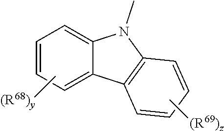
-
-
- in which
- R68, R69 are each independently alkyl, cycloalkyl, heterocycloalkyl, aryl or heteroaryl; preferably methyl, carbazolyl, dibenzofuryl or dibenzothienyl;
- y, z are each independently 0, 1, 2, 3 or 4, preferably 0 or 1.
-
Particularly preferred compounds of the formula (X) have the following formula (Xa):

in which the symbols and indices Q′, T, R55, R56, a″ and b′ are each as defined above.
Very particularly preferred compounds of the formula (X) have the formula (Xaa):

in which the symbols and indices R68, R69 y, z, T, R55, R56, a″ and b′ are each as defined above.
In a very particularly preferred embodiment, in formula (Xaa):
-
- T is O or S, preferably O;
- a″ is 1;
- b′ is 0;
- y, z are each independently 0 or 1; and
- R68, R69 are each independently methyl, carbazolyl, dibenzofuryl or dibenzothienyl
- R55 is substituted phenyl, carbazolyl, dibenzofuryl or dibenzothienyl.
In a further preferred embodiment, the compounds of the formula (X) have the formula (XI) or (XI*):

-
- in which
- T is NR57, S, O or PR57;
- R57 is aryl, heteroaryl, alkyl, cycloalkyl or heterocycloalkyl;
- Q′ is —NR58R59, —P(O)R60R61, —PR62R63, —S(O)2R64, —S(O)R65, —SR66 or —OR67;
- R70, R71, R72 are each independently aryl, heteroaryl, alkyl, cycloalkyl, heterocycloalkyl, where at least one of the R70, R71, R72 radicals comprises at least two carbon atoms, or OR73,
- R55, R56 are each independently alkyl, cycloalkyl, heterocycloalkyl, aryl, heteroaryl, a Q group or a group with donor or acceptor action;
- a′, b′ for the compound of the formula (XI): are each independently 0, 1, 2, 3; for the compound of the formula (XI*), a′ is 0, 1, 2 and b′ is 0, 1, 2, 3, 4;
- R58, R59 form, together with the nitrogen atom, a cyclic radical which has 3 to 10 ring atoms and may be unsubstituted or substituted by one or more substituents selected from alkyl, cycloalkyl, heterocycloalkyl, aryl, heteroaryl and a group with donor or acceptor action and/or may be fused to one or more further cyclic radicals having 3 to 10 ring atoms, where the fused radicals may be unsubstituted or substituted by one or more substituents selected from alkyl, cycloalkyl, heterocycloalkyl, aryl, heteroaryl and a group with donor or acceptor action;
- R73 are each independently SiR74R75R76, aryl, heteroaryl, alkyl, cycloalkyl or heterocycloalkyl, optionally substituted by an OR77 group,
- R77 are each independently SiR74R75R76, aryl, heteroaryl, alkyl, cycloalkyl or heterocycloalkyl,
- R60, R61, R62, R63, R6, R65, R66, R67, R74, R75, R76
- are each independently aryl, heteroaryl, alkyl, cycloalkyl or heterocycloalkyl,
- or
two units of the general formulae (XI) and/or (XI*) are bridged to one another via a linear or branched, saturated or unsaturated bridge optionally interrupted by at least one heteroatom or via O, where this bridge in the general formulae (XI) and/or (XI*) is in each case attached to the silicon atoms in place of R71.
The compounds of the general formula (X) can be used as a matrix (diluent material), hole/exciton blocker, electron/exciton blocker, electron transport material or hole transport material in combination with the complexes claimed, which then serve as emitters. Inventive OLEDs which include both at least one compound of the formula (X) and a compound of the formula (I) exhibit particularly good efficiencies and lifetimes. Depending on the function in which the compound of the formula (X) is used, it is present in pure form or in different mixing ratios. In a particularly preferred embodiment, one or more compounds of the formula (X) are used as matrix material in the light-emitting layer.
For the compounds of the general formula (X), especially for the R55 to R77 radicals:
The terms aryl radical or group, heteroaryl radical or group, alkyl radical or group, cycloalkyl radical or group, heterocycloalkyl radical or group, alkenyl radical or group, alkynyl radical or group, and groups with donor and/or acceptor action are each defined as follows:
An aryl radical (or group) is understood to mean a radical having a base skeleton of 6 to 30 carbon atoms, preferably 6 to 18 carbon atoms, which is formed from an aromatic ring or a plurality of fused aromatic rings. Suitable base skeletons are, for example, phenyl, naphthyl, anthracenyl or phenanthrenyl, indenyl or fluorenyl. This base skeleton may be unsubstituted (which means that all carbon atoms which are substitutable bear hydrogen atoms), or may be substituted at one, more than one or all substitutable positions of the base skeleton.
Suitable substituents are, for example, deuterium, alkoxy radicals, aryloxy radicals, alkylamino groups, arylamino groups, carbazolyl groups, silyl groups, SiR7BR79R80, suitable silyl groups SiR78R79R80 being specified below, alkyl radicals, preferably alkyl radicals having 1 to 8 carbon atoms, more preferably methyl, ethyl or i-propyl, aryl radicals, preferably C6-aryl radicals, which may in turn be substituted or unsubstituted, heteroaryl radicals, preferably heteroaryl radicals which comprise at least one nitrogen atom, more preferably pyridyl radicals and carbazolyl radicals, alkenyl radicals, preferably alkenyl radicals which bear one double bond, more preferably alkenyl radicals having one double bond and 1 to 8 carbon atoms, alkynyl radicals, preferably alkynyl radicals having one triple bond, more preferably alkynyl radicals having one triple bond and 1 to 8 carbon atoms or groups with donor or acceptor action. Suitable groups with donor or acceptor action are specified below. The substituted aryl radicals most preferably bear substituents selected from the group consisting of methyl, ethyl, isopropyl, alkoxy, heteroaryl, halogen, pseudohalogen and amino, preferably arylamino. The aryl radical or the aryl group is preferably a C6-C18-aryl radical, more preferably a C6-aryl radical, which is optionally substituted by at least one or more than one of the aforementioned substituents. The C6-C18-aryl radical, preferably C6-aryl radical, more preferably has none, one, two, three or four, most preferably none, one or two, of the aforementioned substituents.
A heteroaryl radical or a heteroaryl group is understood to mean radicals which differ from the aforementioned aryl radicals in that at least one carbon atom in the base skeleton of the aryl radicals is replaced by a heteroatom, and in that the base skeleton of the heteroaryl radicals preferably has 5 to 18 ring atoms. Preferred heteroatoms are N, O and S. Heteroaryl radicals suitable with particular preference are nitrogen-containing heteroaryl radicals. Most preferably, one or two carbon atoms of the base skeleton are replaced by heteroatoms, preferably nitrogen. The base skeleton is especially preferably selected from systems such as pyridine, pyrimidine and five-membered heteroaromatics such as pyrrole, furan, pyrazole, imidazole, thiophene, oxazole, thiazole, triazole. In addition, the heteroaryl radicals may be fused ring systems, for example benzofuryl, benzothienyl, benzopyrrolyl, dibenzofuryl, dibenzothienyl, phenanthrolinyl, carbazolyl radicals, azacarbazolyl radicals or diazacarbazolyl radicals. The base skeleton may be substituted at one, more than one or all substitutable positions of the base skeleton. Suitable substituents are the same as have already been specified for the aryl groups.
An alkyl radical or an alkyl group is understood to mean a radical having 1 to 20 carbon atoms, preferably 1 to 10 carbon atoms, more preferably 1 to 8, most preferably 1 to 4 carbon atoms. This alkyl radical may be branched or unbranched and optionally be interrupted by one or more heteroatoms, preferably Si, N, O or S, more preferably N, O or S. In addition, this alkyl radical may be substituted by one or more of the substituents specified for the aryl groups. In addition, the alkyl radicals present in accordance with the invention may have at least one halogen atom, for example F, Cl, Br or I, especially F. In a further embodiment, the alkyl radicals present in accordance with the invention may be fully fluorinated. It is likewise possible that the alkyl radical bears one or more (hetero)aryl groups. In the context of the present application, for example, benzyl radicals are thus substituted alkyl radicals. In this context, all of the (hetero)aryl groups listed above are suitable. The alkyl radicals are more preferably selected from the group consisting of methyl, ethyl, isopropyl, n-propyl, n-butyl, iso-butyl and tert-butyl, very particular preference being given to methyl and ethyl.
A cycloalkyl radical or a cycloalkyl group is understood to mean a radical having 3 to 20 carbon atoms, preferably 3 to 10 carbon atoms, more preferably 3 to 8 carbon atoms.
This base skeleton may be unsubstituted (which means that all carbon atoms which are substitutable bear hydrogen atoms) or substituted at one, more than one or all substitutable positions of the base skeleton. Suitable substituents are the groups already mentioned above for the aryl radicals. It is likewise possible that the cycloalkyl radical bears one or more (hetero)aryl groups. Examples of suitable cycloalkyl radicals are cyclopropyl, cyclopentyl and cyclohexyl.
A heterocycloalkyl radical or a heterocycloalkyl group is understood to mean radicals which differ from the aforementioned cycloalkyl radicals in that at least one carbon atom in the base skeleton of the cycloalkyl radicals is replaced by a heteroatom.
Preferred heteroatoms are N, O and S. Most preferably, one or two carbon atoms of the base skeleton of the cycloalkyl radicals are replaced by heteroatoms. Examples of suitable heterocycloalkyl radicals are radicals derived from pyrrolidine, piperidine, piperazine, tetrahydrofuran, dioxane.
An alkenyl radical or an alkenyl group is understood to mean a radical which corresponds to the aforementioned alkyl radicals having at least two carbon atoms, with the difference that at least one C—C single bond of the alkyl radical is replaced by a C—C double bond. The alkenyl radical preferably has one or two double bonds.
An alkynyl radical or an alkynyl group is understood to mean a radical which corresponds to the aforementioned alkyl radicals having at least two carbon atoms, with the difference that at least one C—C single bond of the alkyl radical is replaced by a C—C triple bond. The alkynyl radical preferably has one or two triple bonds.
An SiR78R79R80 group is understood to mean a silyl radical in which
R78, R79 and R80 are each independently alkyl, cycloalkyl, heterocycloalkyl, aryl, heteroaryl or OR73.
An SiR74R75R76 group is understood to mean a silyl radical in which R74, R75 and R76 are each independently alkyl, cycloalkyl, heterocycloalkyl, aryl, heteroaryl or OR73.
In the context of the present application, a group or a substituent with donor or acceptor action is understood to mean the following groups:
Groups with donor action are understood to mean groups which have a +I and/or +M effect, and groups with acceptor action are understood to mean groups which have a −I and/or −M effect. Preferred suitable groups are selected from C1-C20-alkoxy, C6-C30-aryloxy, C1-C20-alkylthio, C6-C30-arylthio, SiR81R82R83, OR73, halogen radicals, halogenated C1-C20-alkyl radicals, carbonyl (—CO(R81)), carbonylthio (—C═O(SR81)), carbonyloxy (—C═O(OR81)), oxycarbonyl (—OC═O(R81)), thiocarbonyl (—SC═O(R81)), amino (—NR81R82), pseudohalogen radicals, amido (—C═O(NR81)), —NR81C═O(R83), phosphonate (—P(O)(OR81)2, phosphate (—OP(O)(OR81)2), phosphine (—PR81R82), phosphine oxide (—P(O)R81 2), sulfate (—OS(O)2OR81), sulfoxide (—S(O)R81), sulfonate (—S(O)2OR81), sulfonyl (—S(O)2R81, sulfonamide (—S(O)2NR81R82), NO2, boronic esters (—OB(OR81)2), imino (—C═NR81R82)), borane radicals, stannane radicals, hydrazine radicals, hydrazone radicals, oxime radicals, nitroso groups, diazo groups, vinyl groups, sulfoximines, alanes, germanes, boroximes and borazines.
The R81, R82 and R83 radicals mentioned in the aforementioned groups with donor or acceptor action are each independently:
-
- substituted or unsubstituted C1-C20-alkyl or substituted or unsubstituted C6-C30-aryl, or OR76, suitable and preferred alkyl and aryl radicals having been specified above. The R81, R82 and R83 radicals are more preferably C1-C6-alkyl, e.g. methyl, ethyl or i-propyl, or phenyl. In a preferred embodiment—in the case of SiR81R82R83—R81, R82 and R83 are preferably each independently substituted or unsubstituted C1-C20-alkyl or substituted or unsubstituted aryl, preferably phenyl.
Preferred substituents with donor or acceptor action are selected from the group consisting of:
-
- C1- to C20-alkoxy, preferably C1-C6-alkoxy, more preferably ethoxy or methoxy; C6-C30-aryloxy, preferably C6-C10-aryloxy, more preferably phenyloxy; SiR81R82R83 where R81, R82 and R83 are preferably each independently substituted or unsubstituted alkyl or substituted or unsubstituted aryl, preferably phenyl; more preferably, at least one of the R81, R82 and R83 radicals is substituted or unsubstituted phenyl, suitable substituents having been specified above; halogen radicals, preferably F, Cl, more preferably F, halogenated C1-C20-alkyl radicals, preferably halogenated C1-C6-alkyl radicals, most preferably fluorinated C1-C6-alkyl radicals, e.g. CF3, CH2F, CHF2 or C2F5; amino, preferably dimethylamino, diethylamino or diarylamino, more preferably diarylamino; pseudohalogen radicals, preferably CN, —C(O)OC1-C4-alkyl, preferably —C(O)OMe, P(O)R2, preferably P(O)Ph2.
Very particularly preferred substituents with donor or acceptor action are selected from the group consisting of methoxy, phenyloxy, halogenated C1-C4-alkyl, preferably CF3, CH2F, CHF2, C2F5, halogen, preferably F, CN, SiR81R82R83, suitable R81, R82 and R83 radicals already having been specified, diarylamino (NR84R85 where R84, R85 are each C6-C30-aryl), —C(O)OC1-C4-alkyl, preferably —C(O)OMe, P(O)Ph2.
Halogen groups are preferably understood to mean F, Cl and Br, more preferably F and Cl, most preferably F.
Pseudohalogen groups are preferably understood to mean CN, SCN and OCN, more preferably CN.
The aforementioned groups with donor or acceptor action do not rule out the possibility that further radicals and substituents mentioned in the present application, but not included in the above list of groups with donor or acceptor action, have donor or acceptor action.
The aryl radicals or groups, heteroaryl radicals or groups, alkyl radicals or groups, cycloalkyl radicals or groups, heterocycloalkyl radicals or groups, alkenyl radicals or groups and groups with donor and/or acceptor action may—as mentioned above—be substituted or unsubstituted. In the context of the present application, an unsubstituted group is understood to mean a group in which the substitutable atoms of the group bear hydrogen atoms. In the context of the present application, a substituted group is understood to mean a group in which one or more substitutable atom(s) bear(s) a substituent in place of a hydrogen atom at least at one position. Suitable substituents are the substituents specified above for the aryl radicals or groups.
When radicals having the same numbering occur more than once in the compounds according to the present application, these radicals may each independently have the definitions specified.
The T radical in the compounds of the formula (X) is NR57, S, O or PR57, preferably NR57, S or O, more preferably O or S, most preferably O.
The R57 radical is aryl, heteroaryl, alkyl, cycloalkyl or heterocycloalkyl, preferably aryl, heteroaryl or alkyl, more preferably aryl, where the aforementioned radicals may be unsubstituted or substituted. Suitable substituents have been specified above. R65 is more preferably phenyl which may be substituted by the aforementioned substituents or unsubstituted. R57 is most preferably unsubstituted phenyl.
The Q′ group in the compounds of the formula (X) is —NR58R69, —P(O)R60R61, —PR62R63, —S(O)2R64, —S(O)R65, —SR66 or —OR67; preferably NR58R59, —P(O)R60R61 or —OR67, more preferably —NR58R59.
The R58 to R67 and R74 to R76 radicals are each defined as follows:
-
- R58, R59 form, together with the nitrogen atom, a cyclic radical which has 3 to 10 ring atoms and may be unsubstituted or substituted by one or more substituents selected from alkyl, cycloalkyl, heterocycloalkyl, aryl, heteroaryl and a group with donor or acceptor action and/or may be fused to one or more further cyclic radicals having 3 to 10 ring atoms, where the fused radicals may be unsubstituted or substituted by one or more substituents selected from alkyl, cycloalkyl, heterocycloalkyl, aryl, heteroaryl and a group with donor or acceptor action;
- R60, R61, R62, R63, R64, R65, R66, R67, R74, R75, R76
- are each independently aryl, heteroaryl, alkyl, cycloalkyl or heterocycloalkyl, preferably aryl or heteroaryl, where the radicals may be unsubstituted or substituted by one or more of the radicals selected from alkyl, cycloalkyl, heterocycloalkyl, aryl, heteroaryl and a group with donor or acceptor action, more preferably unsubstituted or substituted phenyl, suitable substituents having been specified above, for example tolyl or a group of the formula

-
-
- in which the T group and the R70, R71 and R72 radicals are each independently as defined for the compounds of the formula (XI) or (XI*).
- R60, R6′, R62, R63, R6, R65, R66 and R67 are most preferably each independently phenyl, tolyl or a group of the formula
-

in which T is NPh, S or O.
Examples of —NR58R59 groups suitable with preference are selected from the group consisting of pyrrolyl, 2,5-dihydro-1-pyrrolyl, pyrrolidinyl, indolyl, indolinyl, isoindolinyl, carbazolyl, azacarbazolyl, diazacarbazolyl, imidazolyl, imidazolinyl, benzimidazolyl, pyrazolyl, indazolyl, 1,2,3-triazolyl, benzotriazolyl, 1,2,4-triazolyl, tetrazolyl, 1,3-oxazolyl, 1,3-thiazolyl, piperidyl, morpholinyl, 9,10-dihydroacridinyl and 1,4-oxazinyl, where the aforementioned groups may be unsubstituted or substituted by one or more substituents selected from alkyl, cycloalkyl, heterocycloalkyl, aryl, heteroaryl and a group with donor or acceptor action; the —NR58R59 group is preferably selected from carbazolyl, pyrrolyl, indolyl, imidazolyl, benzimidazolyl, azacarbazolyl and diazacarbazolyl, where the aforementioned groups may be unsubstituted or substituted by one or more substituents selected from alkyl, cycloalkyl, heterocycloalkyl, aryl, heteroaryl and a group with donor or acceptor action; the —NR58R59 group is more preferably carbazolyl which may be unsubstituted or substituted by one or more substituents selected from alkyl, cycloalkyl, heterocycloalkyl, aryl, heteroaryl and a group with donor or acceptor action.
Particularly preferred —NR58R59 groups are:

-
- in which
- R68, R69 are each independently alkyl, cycloalkyl, heterocycloalkyl, aryl or heteroaryl; preferably methyl, carbazolyl, dibenzofuryl or dibenzothienyl;
- y, z are each independently 0, 1, 2, 3 or 4, preferably 0 or 1;
- for example:

in which X is NPh, S or O;

in which X is NPh, S or

Particularly preferred —P(O)R60R61 groups are:

A particularly preferred PR62R63 group is:

Particularly preferred groups —S(O)2R64 and —S(O)R65 are:

Particularly preferred groups —SR66 and —OR67 are:

in which T is in each case NPh, S or O.
R55, R56 in the compounds of the formula (X) are each independently alkyl, cycloalkyl, heterocycloalkyl, aryl, heteroaryl, a further A group or a group with donor or acceptor action; preferably each independently alkyl, aryl, heteroaryl or a group with donor or acceptor action. For example, R55 or R56 may each independently be:

in which X is NPh, S or O.
In the compounds of the formula (X) a″ R55 groups and/or b′ R56 groups may be present, where a″ and b′ are:
-
- a″ is 0, 1, 2, 3 or 4; preferably independently 0, 1 or 2;
- b′ is 0, 1, 2 or 3; preferably independently 0, 1 or 2.
Most preferably at least a″ or b′ is 0, very especially preferably a″ and b′ are each 0 or a″ is 1 and b′ is 0.
R73 in the compounds of the general formula (XI) is generally independently SiR74R75R76, aryl, heteroaryl, alkyl, cycloalkyl or heterocycloalkyl, optionally substituted by an OR77 group.
R77 in compounds of the general formula (XI) is generally independently aryl, heteroaryl, alkyl, cycloalkyl or heterocycloalkyl.
The OR77 substituent optionally present may generally be present in the radicals mentioned at all sites which appear suitable to the person skilled in the art.
In a further embodiment, two units of the general formula (XI) and/or (XI*) are bridged to one another via a linear or branched, saturated or unsaturated bridge optionally interrupted by at least one heteroatom or via 0, where this bridge in the general formula (XI) and/or (XI*) is in each case attached to the silicon atoms in place of R71.
This bridge is preferably selected from the group consisting of —CH2—, —C2H4—, —C3H6—, —C4H8—, —C6H12—, —C8H16—, —C9H18—, —CH(C8H17)CH2—, —C2H4(CF2)8C2H4-, —C≡C—, -1,4-(CH2)2-phenyl-(CH2)2—, 1,3-(CH2)2-phenyl-(CH2)2—, -1,4-phenyl-, -1,3-phenyl-, —O—, —O—Si(CH3)2—O—, —O—Si(CH3)2—O— Si(CH3)2—O—, —O—In a preferred embodiment of the present application, the compounds of the general formula (X) have the general formula (XIa), (XIb), (XIc), (XId) or (XIe), i.e. they are preferred embodiments of the compounds of the general formula (XI) or (XI*):

in which the Q′, T, R70, R71, R72, R55, R56 radicals and groups, and a′ and b′, are each as defined above.
In another embodiment preferred in accordance with the invention, R70, R71 or R72 in the compounds of the general formula (XI) or (XI*) are aromatic units of the general formulae (XIi) and/or (XIi*)

where R55, R56, Q′, T, a′ and b′ are each as defined above.
The present invention therefore relates, in one embodiment, to an inventive OLED where R70, R71 or R72 in the compounds of the general formula (XI) or (XI*) are aromatic units of the general formulae (XIi) and/or (XIi*)

where R56, R56, Q′, T, a′ and b′ are each as defined above.
In a preferred embodiment, the present invention relates to an OLED wherein the compound of the general formula (XI) or (XI*) is selected from the following group:


In these particularly preferred compounds of the general formula (XI) or (XI*):
-
- T is S or O, and
- R′ is H or CH3; and
- R70, R71, R72 are each phenyl, carbazolyl, dibenzofuran or dibenzothiophene.
Further particularly suitable compounds of the general formula (XI) or (XI*) are:


In these particularly preferred compounds of the general formula (XI) or (XI*) too, T is O or S, preferably O.
Further inventive compounds of the general formula (XI) or (XI*) correspond to the following formula (XII)

In the general formula (XII), R70, R71, R72 are each defined as follows:
| No. | R70 | R71 | R72 |
| 1 | methyl | methyl | ethyl |
| 2 | methyl | methyl | i-propyl |
| 3 | methyl | methyl | n-propyl |
| 4 | methyl | methyl | n-butyl |
| 5 | methyl | methyl | i-butyl |
| 6 | methyl | methyl | t-butyl |
| 7 | methyl | methyl | n-pentyl |
| 8 | methyl | methyl | n-hexyl |
| 9 | methyl | methyl | —CH2CH2C(CH3)3 |
| 10 | methyl | methyl | n-C8H17 |
| 11 | methyl | methyl | i-C8H17 |
| 12 | methyl | methyl | n-C10H21 |
| 13 | methyl | methyl | n-C12H25 |
| 16 | methyl | methyl | n-C18H37 |
| 17 | methyl | methyl | n-C30H61 |
| 19 | methyl | methyl | cyclohexyl |
| 20 | methyl | methyl | C(CH3)2Ph |
| 21 | methyl | methyl | —C(CH3)2CH(CH3)2 |
| 22 | methyl | methyl | —CCH2CH(CH3)(C2H5) |
| 23 | methyl | methyl | —CH2CH(C10H21)2 |
| 24 | methyl | methyl | —CH2CH(C12H25)2 |
| 25 | methyl | methyl | —CH2CH2(C3F6)CF3 |
| 26 | methyl | methyl | —CH2CH2(C7F14)CF3 |
| 27 | methyl | methyl | —CH2CH2(C5F10)CF3 |
| 29 | methyl | methyl | —CH2CH2CF3 |
| 30 | methyl | methyl | phenyl |
| 31 | methyl | methyl | 2-biphenyl |
| 32 | methyl | methyl | p-tolyl |
| 33 | methyl | methyl | C6F5 |
| 34 | methyl | methyl | 3,5-(CF3)2phenyl |
| 35 | methyl | methyl | —CH2C(CH3)2phenyl |
| 36 | methyl | methyl | 9-fluorenyl |
| 37 | methyl | methyl | 3,6-di(tert-butyl)-9-fluorenyl |
| 15 | methyl | methyl | R86 |
| 38 | methyl | methyl | —OMe |
| 39 | methyl | methyl | —OEt |
| 40 | methyl | methyl | 2,4,6-t-butylphenoxy |
| 41 | methyl | methyl | —O—tBu (tert-butoxy) |
| 42 | methyl | methyl | —OSiEt3 |
| 43 | methyl | ethyl | ethyl |
| 44 | methyl | ethyl | phenyl |
| 45 | methyl | ethyl | R86 |
| 46 | methyl | n-propyl | n-propyl |
| 47 | methyl | n-propyl | phenyl |
| 48 | methyl | n-propy! | R86 |
| 49 | methyl | i-propyl | i-propyl |
| 50 | methyl | i-propyl | phenyl |
| 51 | methyl | i-propyl | R86 |
| 52 | methyl | n-butyl | n-butyl |
| 53 | methyl | n-butyl | phenyl |
| 54 | methyl | n-butyl | R86 |
| 55 | methyl | i-butyl | i-butyl |
| 56 | methyl | i-butyl | phenyl |
| 57 | methyl | i-butyl | R86 |
| 58 | methyl | t-butyl | t-butyl |
| 59 | methyl | t-butyl | phenyl |
| 60 | methyl | t-butyl | R86 |
| 61 | methyl | n-pentyl | n-pentyl |
| 62 | methyl | n-pentyl | n-hexyl |
| 63 | methyl | n-pentyl | phenyl |
| 64 | methyl | n-pentyl | R86 |
| 65 | methyl | n-hexyl | hexyl |
| 66 | methyl | n-hexyl | phenyl |
| 67 | methyl | n-hexyl | R86 |
| 68 | methyl | n-heptyl | R86 |
| 69 | methyl | n-octyl | R86 |
| 70 | methyl | n-decyl | R86 |
| 71 | methyl | n-C12H25 | R86 |
| 72 | methyl | n-C18H37 | R86 |
| 73 | methyl | n-C22H45 | R86 |
| 74 | methyl | n-C30H61 | R86 |
| 75 | methyl | cyclopentyl | cyclopentyl |
| 76 | methyl | cyclopentyl | phenyl |
| 77 | methyl | cyclopentyl | R86 |
| 78 | methyl | cyclohexyl | cyclohexyl |
| 79 | methyl | cyclohexyl | phenyl |
| 80 | methyl | cyclohexyl | R86 |
| 81 | methyl | —CF2CHF2 | R86 |
| 82 | methyl | —CH2CH2CF3 | R86 |
| 83 | methyl | —CH2CH2(CF2)3CF3 | R86 |
| 84 | methyl | —CH2CH2(CF2)5CF3 | R86 |
| 85 | methyl | —CH2CH2(CF2)7CF3 | R86 |
| 86 | methyl | phenyl | phenyl |
| 87 | methyl | phenyl | p-tolyl |
| 89 | methyl | phenyl | mesityl |
| 90 | methyl | phenyl | R86 |
| 91 | methyl | p-tolyl | p-tolyl |
| 92 | methyl | p-tolyl | R86 |
| 93 | methyl | mesityl | mesityl |
| 94 | methyl | mesityl | R5 |
| 95 | methyl | R86 | R86 |
| 96 | methyl | methoxy | methoxy |
| 97 | methyl | ethoxy | ethoxy |
| 98 | methyl | —OSiEt3 | —OSiEt3 |
| 99 | methyl | —O—SiMe2— | —O—SiMe2—CH2CH2(CF2)4CF3 |
| CH2CH2(CF2)4CF3 | |||
| 100 | ethyl | ethyl | ethyl |
| 101 | ethyl | ethyl | n-propyl |
| 102 | ethyl | ethyl | i-propyl |
| 103 | ethyl | ethyl | n-butyl |
| 104 | ethyl | ethyl | i-butyl |
| 105 | ethyl | ethyl | t-butyl |
| 106 | ethyl | ethyl | phenyl |
| 107 | ethyl | ethyl | R5 |
| 108 | ethyl | phenyl | phenyl |
| 109 | ethyl | phenyl | R86 |
| 110 | ethyl | R86 | R86 |
| 111 | ethyl | ethoxy | ethoxy |
| 112 | n-propyl | n-propyl | n-propyl |
| 113 | n-propyl | n-propyl | phenyl |
| 114 | n-propyl | n-propyl | R86 |
| 115 | n-propyl | phenyl | phenyl |
| 116 | n-propyl | phenyl | R86 |
| 117 | n-propyl | R86 | R86 |
| 118 | i-propyl | i-propyl | i-propyl |
| 119 | i-propyl | i-propyl | phenyl |
| 120 | i-propyl | i-propyl | R86 |
| 121 | i-propyl | i-propyl | 2-biphenyl |
| 122 | i-propyl | i-propyl | ethoxy |
| 123 | i-propyl | phenyl | phenyl |
| 124 | i-propyl | phenyl | R86 |
| 125 | i-propyl | R86 | R86 |
| 126 | n-butyl | n-butyl | n-butyl |
| 127 | n-butyl | n-butyl | phenyl |
| 128 | n-butyl | n-butyl | R86 |
| 129 | n-butyl | n-hexyl | R86 |
| 130 | n-butyl | phenyl | phenyl |
| 131 | n-butyl | phenyl | R86 |
| 132 | n-butyl | R86 | R86 |
| 133 | sec-butyl | sec-butyl | sec-butyl |
| 134 | sec-butyl | sec-butyl | phenyl |
| 135 | sec-butyl | sec-butyl | R86 |
| 136 | sec-butyl | phenyl | phenyl |
| 137 | sec-butyl | phenyl | R86 |
| 138 | sec-butyl | R86 | R86 |
| 139 | i-butyl | i-butyl | i-butyl |
| 140 | i-butyl | i-butyl | n-C8H17 |
| 141 | i-butyl | i-butyl | n-C18H37 |
| 142 | i-butyl | i-butyl | phenyl |
| 143 | i-butyl | i-butyl | R86 |
| 144 | i-butyl | phenyl | phenyl |
| 145 | i-butyl | phenyl | R86 |
| 146 | i-butyl | R86 | R86 |
| 147 | t-butyl | t-butyl | t-butyl |
| 148 | t-butyl | t-butyl | n-C8H17 |
| 149 | t-butyl | t-butyl | phenyl |
| 150 | t-butyl | t-butyl | R86 |
| 151 | t-butyl | phenyl | phenyl |
| 152 | t-butyl | phenyl | R5 |
| 153 | t-butyl | R86 | R86 |
| 154 | n-pentyl | n-pentyl | n-pentyl |
| 155 | n-pentyl | n-pentyl | phenyl |
| 156 | n-pentyl | n-pentyl | R86 |
| 157 | n-pentyl | phenyl | phenyl |
| 158 | n-pentyl | phenyl | R86 |
| 159 | n-pentyl | R86 | R86 |
| 160 | cyclopentyl | cyclopentyl | cyclopentyl |
| 161 | cyclopentyl | cyclopentyl | phenyl |
| 162 | cyclopentyl | cyclopentyl | R86 |
| 163 | cyclopentyl | phenyl | phenyl |
| 164 | cyclopentyl | phenyl | R86 |
| 165 | cyclopentyl | R86 | R86 |
| 166 | n-hexyl | n-hexyl | n-hexyl |
| 167 | n-hexyl | n-hexyl | phenyl |
| 168 | n-hexyl | n-hexyl | R86 |
| 169 | n-hexyl | phenyl | phenyl |
| 170 | n-hexyl | phenyl | R86 |
| 171 | n-hexyl | R86 | R86 |
| 172 | —CH2CH2C(CH3)3 | —CH2CH2C(CH3)3 | —CH2CH2C(CH3)3 |
| 173 | —CH2CH2C(CH3)3 | —CH2CH2C(CH3)3 | R86 |
| 174 | —CH2CH2C(CH3)3 | R86 | R86 |
| 175 | t-hexyl | t-hexyl | t-hexyl |
| 176 | t-hexyl | t-hexyl | R86 |
| 177 | t-hexyl | R86 | R86 |
| 178 | n-heptyl | n-heptyl | n-heptyl |
| 179 | n-heptyl | n-heptyl | R86 |
| 180 | n-heptyl | R86 | R86 |
| 181 | n-octyl | n-octyl | n-octyl |
| 182 | n-octyl | n-octyl | R86 |
| 183 | n-octyl | R86 | R86 |
| 184 | i-octyl | i-octyl | i-octyl |
| 185 | i-octyl | i-octyl | R86 |
| 186 | i-octyl | R86 | R86 |
| 187 | n-nonyl | n-nonyl | n-nonyl |
| 188 | n-nonyl | n-nonyl | R86 |
| 189 | n-nonyl | R86 | R86 |
| 190 | cyclohexyl | cyclohexyl | cyclohexyl |
| 191 | cyclohexyl | cyclohexyl | R86 |
| 192 | cyclohexyl | R86 | R86 |
| 193 | cyclooctyl | cyclooctyl | cyclooctyl |
| 194 | cyclooctyl | cyclooctyl | R86 |
| 195 | cyclooctyl | R86 | R86 |
| 196 | n-C10H21 | n-C10H21 | n-C10H21 |
| 197 | n-C10H21 | n-C10H21 | R86 |
| 198 | n-C10H21 | R86 | R86 |
| 199 | n-C11H23 | n-C11H23 | n-C11H23 |
| 200 | n-C11H23 | n-C11H23 | R86 |
| 201 | n-C11H23 | R86 | R86 |
| 202 | n-C12H25 | n-C12H25 | n-C12H25 |
| 203 | n-C12H25 | n-C12H25 | R86 |
| 204 | n-C12H25 | R86 | R86 |
| 205 | n-C14H29 | n-C14H29 | n-C14H29 |
| 206 | n-C14H29 | n-C14H29 | R86 |
| 207 | n-C14H29 | R86 | R86 |
| 208 | n-C16H33 | n-C16H33 | n-C16H33 |
| 209 | n-C16H33 | n-C16H33 | R86 |
| 210 | n-C16H33 | R86 | R86 |
| 211 | n-C18H37 | n-C18H37 | R86 |
| 212 | n-C18H37 | R86 | R86 |
| 213 | n-C18H37 | OEt | OEt |
| 214 | n-C18H37 | R86 | OMe |
| 215 | n-C20H41 | n-C20H41 | n-C20H41 |
| 216 | n-C20H41 | n-C20H41 | R86 |
| 217 | n-C20H41 | R86 | R86 |
| 218 | n-C22H45 | n-C22H45 | n-C22H45 |
| 219 | n-C22H45 | n-C22H45 | R86 |
| 220 | n-C22H45 | R86 | R86 |
| 221 | n-C26H53 | n-C26H53 | n-C26H53 |
| 222 | n-C26H53 | n-C26H53 | R86 |
| 223 | n-C26H53 | R86 | R86 |
| 224 | n-C30H61 | n-C30H61 | n-C30H61 |
| 225 | n-C30H61 | n-C30H61 | R86 |
| 226 | n-C30H61 | R86 | R86 |
| 227 | —CH2-cyclohexyl | —CH2-cyclohexyl | R86 |
| 228 | —CH2CH2CF3 | —CH2CH2CF3 | —CH2CH2CF3 |
| 229 | —CH2CH2CF3 | —CH2CH2CF3 | R86 |
| 230 | —CH2CH2CF3 | R86 | R86 |
| 231 | —CH2CH2(CF2)3CF3 | —CH2CH2(CF2)3CF3 | —CH2CH2(CF2)3CF3 |
| 232 | —CH2CH2(CF2)3CF3 | —CH2CH2(CF2)3CF3 | R86 |
| 233 | —CH2CH2(CF2)3CF3 | R86 | R86 |
| 234 | —CH2CH2(CF2)5CF3 | —CH2CH2(CF2)5CF3 | —CH2CH2(CF2)5CF3 |
| 235 | —CH2CH2(CF2)5CF3 | —CH2CH2(CF2)5CF3 | R86 |
| 236 | —CH2CH2(CF2)5CF3 | R86 | R86 |
| 237 | —CH2CH2(CF2)7CF3 | —CH2CH2(CF2)7CF3 | —CH2CH2(CF2)7CF3 |
| 238 | —CH2CH2(CF2)7CF3 | —CH2CH2(CF2)7CF3 | R86 |
| 239 | —CH2CH2(CF2)7CF3 | R86 | R86 |
| 240 | —CH2CH2(CF2)9CF3 | —CH2CH2(CF2)9CF3 | —CH2CH2(CF2)9CF3 |
| 241 | —CH2CH2(CF2)9CF3 | —CH2CH2(CF2)9CF3 | R86 |
| 242 | —CH2CH2(CF2)9CF3 | R86 | R86 |
| 243 | —CH2CH2(CF2)11CF3 | —CH2CH2(CF2)11CF3 | —CH2CH2(CF2)11CF3 |
| 244 | —CH2CH2(CF2)11CF3 | —CH2CH2(CF2)11CF3 | R86 |
| 245 | —CH2CH2(CF2)11CF3 | R86 | R86 |
| 246 | —CF2CHF2 | —CF2CHF2 | —CF2CHF2 |
| 247 | —CF2CHF2 | —CF2CHF2 | R86 |
| 248 | —CF2CHF2 | R86 | R86 |
| 249 | —(CF2)3CHF2 | —(CF2)3CHF2 | —(CF2)3CHF2 |
| 250 | —(CF2)3CHF2 | —(CF2)3CHF2 | R86 |
| 251 | —(CF2)3CHF2 | R86 | R86 |
| 14 | phenyl | phenyl | phenyl |
| 252 | phenyl | phenyl | p-tolyl |
| 253 | phenyl | phenyl | m-tolyl |
| 254 | phenyl | phenyl | o-tolyl |
| 255 | phenyl | phenyl | 2-xylyl |
| 256 | phenyl | phenyl | 5-xylyl |
| 257 | phenyl | phenyl | mesityl |
| 258 | phenyl | phenyl | 9-fluorenyl |
| 18 | phenyl | phenyl | R86 |
| 259 | phenyl | phenyl | —O—tBu (tert-butoxy) |
| 260 | phenyl | p-tolyl | p-tolyl |
| 261 | phenyl | m-tolyl | m-tolyl |
| 262 | phenyl | o-tolyl | o-tolyl |
| 263 | phenyl | 2-xylyl | 2-xylyl |
| 264 | phenyl | 5-xylyl | 5-xylyl |
| 265 | phenyl | mesityl | mesityl |
| 266 | phenyl | R86 | R86 |
| 267 | phenyl | ethoxy | ethoxy |
| 268 | p-tolyl | p-tolyl | p-tolyl |
| 269 | p-tolyl | p-tolyl | R86 |
| 270 | p-toly I | R86 | R86 |
| 271 | m-tolyl | m-tolyl | m-tolyl |
| 272 | m-tolyl | m-tolyl | R86 |
| 273 | o-tolyl | o-tolyl | o-tolyl |
| 274 | o-tolyl | o-tolyl | R86 |
| 275 | 2-xylyl | 2-xylyl | 2-xylyl |
| 276 | 2-xylyl | 2-xylyl | R86 |
| 277 | 5-xylyl | 5-xylyl | 5-xylyl |
| 278 | 5-xylyl | 5-xylyl | R86 |
| 279 | mesityl | mesityl | mesityl |
| 280 | mesityl | mesityl | R86 |
| 281 | C6F5 | C6F5 | C6F5 |
| 282 | C6F5 | C6F5 | R86 |
| 283 | C6F5 | R86 | R86 |
| 284 | R86 | R86 | R86 |
| 285 | R86 | ethoxy | ethoxy |
| 286 | R86 | n-butoxy | n-butoxy |
| 287 | R86 | R86 | methoxy |
| 288 | R86 | R86 | ethoxy |
| 289 | R86 | R86 | OSiMe3 |
| 290 | R86 | R86 | —(CH2)11O—(CH2)2OCH3 |
| 291 | methoxy | methoxy | methoxy |
| 292 | ethoxy | ethoxy | ethoxy |
| 293 | i-propoxy | i-propoxy | i-propoxy |
| 294 | t-butoxy | t-butoxy | t-butoxy |
| 295 | OSiMe3 | OSiMe3 | OSiMe3 |
| 296 | cyclobutyl | methyl |
| 297 | cyclobutyl | R86 |
| 298 | cyclobutyl | p-methoxyphenyl |
| 299 | cyclopentyl | methyl |
| 300 | cyclopentyl | R86 |
| 301 | cyclohexyl | methyl |
| 302 | cyclohexyl | R86 |
In this table,

Particularly preferred compounds in which two units of the general formulae (XI) and/or (XI*) are bridged to one another via a linear or branched, saturated or unsaturated bridge optionally interrupted by at least one heteroatom or via 0, where this bridge in the general formulae (XI) and/or (XI*) is in each case attached to the silicon atoms in place of R71, correspond to the general formula (XIII)

In formula (XIII), U, R70, R71, R72, R87, R88 and R89 are each defined as follows:
| No. | R70 | R71 | R72 | R87 | R88 | R89 | U |
| 303 | methyl | R86 | R86 | methyl | R5 | R86 | —CH2— |
| 304 | methyl | methyl | R86 | methyl | methyl | R86 | CH2 |
| 305 | R86 | R86 | R86 | R86 | R86 | R86 | CH2 |
| 306 | methyl | R86 | R86 | methyl | R5 | R86 | C2H4 |
| 307 | methyl | methyl | R86 | methyl | methyl | R86 | C2H4 |
| 308 | R86 | R86 | R86 | R86 | R86 | R86 | C2H4 |
| 309 | methyl | R86 | R86 | methyl | R86 | R86 | C3H6 |
| 310 | methyl | methyl | R86 | methyl | methyl | R86 | C3H6 |
| 311 | R86 | R86 | R86 | R86 | R86 | R86 | C3H6 |
| 312 | methyl | R86 | R86 | methyl | R86 | R86 | C4H8 |
| 313 | methyl | methyl | R86 | methyl | methyl | R86 | C4H8 |
| 314 | R86 | R86 | R86 | R86 | R86 | R86 | C4H8 |
| 315 | methyl | R86 | R86 | methyl | R86 | R86 | C6H12 |
| 316 | methyl | methyl | R86 | methyl | methyl | R86 | C6H12 |
| 317 | R86 | R86 | R86 | R86 | R86 | R86 | C6H12 |
| 318 | methyl | R86 | R86 | methyl | R86 | R86 | C8H16 |
| 319 | methyl | methyl | R86 | methyl | methyl | R86 | C8H16 |
| 320 | R86 | R86 | R86 | R86 | R86 | R86 | C8H16 |
| 321 | methyl | R86 | R86 | methyl | R86 | R86 | C9H18 |
| 322 | methyl | methyl | R86 | methyl | methyl | R86 | C9H18 |
| 323 | R86 | R86 | R86 | R86 | R86 | R86 | C9H18 |
| 324 | R86 | R86 | R86 | R86 | R86 | R86 | CH(C8H17)CH2 |
| 325 | methyl | R86 | R86 | methyl | R86 | R86 | C2H4(CF2)8C2H4 |
| 326 | methyl | methyl | R86 | methyl | methyl | R86 | C2H4(CF2)8C2H4 |
| 327 | R86 | R86 | R86 | R86 | R86 | R86 | C2H4(CF2)8C2H4 |
| 328 | methyl | R86 | R86 | methyl | R86 | R86 | C≡C |
| 329 | methyl | methyl | R86 | methyl | methyl | R86 | C≡C |
| 330 | R86 | R86 | R86 | R86 | R86 | R86 | C≡C |
| 331 | methyl | R86 | R86 | methyl | R86 | R86 | -1,4-(CH2)2-phenyl- |
| (CH2)2- | |||||||
| 332 | methyl | methyl | R86 | methyl | methyl | R86 | -1,4-(CH2)2-phenyl- |
| (CH2)2- | |||||||
| 333 | R86 | R86 | R86 | R86 | R86 | R86 | -1,4-(CH2)2-phenyl- |
| (CH2)2 | |||||||
| 334 | methyl | R86 | R86 | methyl | R86 | R86 | -1,3-(CH2)2-phenyl- |
| (CH2)2 | |||||||
| 335 | methyl | methyl | R86 | methyl | methyl | R86 | -1,3-(CH2)2-phenyl- |
| (CH2)2 | |||||||
| 336 | R86 | R86 | R86 | R86 | R86 | R86 | -1,3-(CH2)2-phenyl- |
| (CH2)2- | |||||||
| 337 | methyl | R86 | R86 | methyl | R86 | R86 | -1,4-(CH2)3-phenyl- |
| (CH2)3- | |||||||
| 338 | methyl | methyl | R86 | methyl | methyl | R86 | -1,4-(CH2)3-phenyl- |
| (CH2)3- | |||||||
| 339 | R86 | R86 | R86 | R86 | R86 | R86 | -1,4-(CH2)3-phenyl- |
| (CH2)3- | |||||||
| 340 | methyl | R86 | R86 | methyl | R86 | R86 | -1,3-(CH2)3-phenyl- |
| (CH2)3- | |||||||
| 341 | methyl | methyl | R86 | methyl | methyl | R86 | -1,3-(CH2)3-phenyl- |
| (CH2)3- | |||||||
| 342 | R86 | R86 | R86 | R86 | R86 | R86 | -1,3-(CH2)3-phenyl- |
| (CH2)3- | |||||||
| 343 | methyl | R86 | R86 | methyl | R86 | R86 | -1,4-phenyl- |
| 344 | methyl | methyl | R86 | methyl | methyl | R86 | -1,4-phenyl- |
| 345 | R86 | R86 | R86 | R86 | R86 | R86 | -1,4-phenyl- |
| 346 | methyl | R86 | R86 | methyl | R86 | R86 | -1,3-phenyl- |
| 347 | methyl | methyl | R86 | methyl | methyl | R86 | -1,3-phenyl- |
| 348 | R86 | R86 | R86 | R86 | R86 | R86 | -1,3-phenyl- |
| 28 | methyl | methyl | R86 | methyl | methyl | R86 | O |
| 349 | methyl | R86 | R86 | methyl | R86 | R86 | O |
| 350 | methyl | methyl | R86 | methyl | methyl | R86 | O Si(CH3)2 O |
| 351 | methyl | methyl | R86 | methyl | methyl | R86 | O Si(CH3)(Ph) O |
| 352 | methyl | methyl | R86 | methyl | methyl | R86 | O Si(CH3)2 O |
| Si(CH3)2 O | |||||||
| 353 | methyl | methyl | R86 | methyl | methyl | R86 | O Si(CH3)2 O |
| Si(CH3)2 O | |||||||
| Si(CH3)2 O | |||||||
| 354 | methyl | OSiMe3 | R86 | methyl | OSiMe3 | R86 | O |
| 355 | methyl | phenyl | R86 | methyl | phenyl | R86 | O |
| 356 | i-propyl | i-propyl | R86 | i-propyl | i-propyl | R86 | O |
| 357 | cyclopentyl | cyclopentyl | R86 | cyclopentyl | cyclopentyl | R86 | O |
| 358 | phenyl | phenyl | R86 | phenyl | phenyl | R86 | O |
| 359 | phenyl | R86 | R86 | phenyl | R86 | R86 | O |
| 360 | R86 | R86 | R86 | R86 | R86 | R86 | O |
In this table,

Further suitable compounds of the formula (XI) and/or (XI*) are specified hereinafter. R therein is independently Me, phenyl or R86, where at least one R radical is R86:


In a very particularly preferred embodiment, the present invention relates to an OLED which, as well as at least one metal-carbene complex of the general formula (I), comprises at least one compound of the general formula (X), in which case the compound of the formula (X) is most preferably at least one of the compounds specified below:


In the aforementioned compounds, T is O or S, preferably O. When more than one T occurs in the molecule, all T groups have the same definition.
In addition to the compounds of the formula (X), according to the present invention, it is also possible to use crosslinked or polymeric materials comprising repeat units based on the general formula (X) in crosslinked or polymerized form together with at least one metal-carbene complex of the general formula (I). Like the compounds of the general formula (X), the latter are preferably used as matrix materials.
The crosslinked or polymeric materials have outstanding solubility in organic solvents, excellent film-forming properties and relatively high glass transition temperatures. In addition, high charge carrier mobilities, high stabilities of color emission and long operating times of the corresponding components can be observed when crosslinked or polymeric materials according to the present invention are used in organic light-emitting diodes (OLEDs).
The crosslinked or polymerized materials are particularly suitable as coatings or in thin films since they are thermally and mechanically stable and relatively defect-free.
The crosslinked or polymerized materials comprising repeat units based on the general formula (X) can be prepared by a process comprising steps (a) and (b):
-
- (a) preparation of a crosslinkable or polymerizable compound of the general formula (X) where at least one of the a″ R55 radicals or at least one of the b′ R56 radicals is a crosslinkable or polymerizable group attached via a spacer, and
- (b) crosslinking or polymerization of the compound of the general formula (X) obtained from step (a).
The crosslinked or polymerized materials may be homopolymers, which means that exclusively units of the general formula (X) are present in crosslinked or polymerized form. They may also be copolymers, which means that further monomers are present in addition to the units of the general formula (X), for example monomers with hole-conducting and/or electron-conducting properties, in crosslinked or polymerized form.
In a further preferred embodiment of the inventive OLED, it comprises an emission layer comprising at least one inventive metal-carbene complex of the general formula (I), at least one matrix material of the formula (X), and optionally at least one further hole-transporting matrix material.
The inventive OLEDs can be used in all devices in which electroluminescence is useful. Suitable devices are preferably selected from stationary and mobile visual display units and illumination means. The present invention therefore also relates to a device selected from the group consisting of stationary visual display units and mobile visual display units and illumination means, comprising an inventive OLED.
Stationary visual display units are, for example, visual display units of computers, televisions, visual display units in printers, kitchen appliances and advertising panels, illuminations and information panels. Mobile visual display units are, for example, visual display units in cellphones, laptops, digital cameras, mp-3 players, smartphones, vehicles, and destination displays on buses and trains.
The inventive metal-carbene complexes of the general formula (I) can additionally be used in OLEDs with inverse structure. In these inverse OLEDs, the inventive complexes are in turn preferably used in the light-emitting layer. The structure of inverse OLEDs and the materials typically used therein are known to those skilled in the art.
The present invention further provides a white OLED comprising at least one inventive metal-carbene complex of the general formula (I). In a preferred embodiment, the metal-carbene complex of the general formula (I) is used as emitter material in the white OLED. Preferred embodiments of the metal-carbene complex of the general formula (I) have been specified above. In addition to the at least one metal-carbene complex of the general formula (I), the white OLED may comprise
-
- (i) at least one compound of the formula (X). The compound of the formula (X) is preferably used as matrix material. Preferred compounds of the formula (X) have been specified above; and/or
- (ii) at least one compound of the formula (VII) and/or (IX). The compounds of the formula (VII) and/or (IX) are preferably used as electron transport material. Preferred compounds of the formulae (VII) and (IX) have been specified above.
In order to obtain white light, the OLED must generate light which colors the entire visible range of the spectrum. However, organic emitters normally emit only in a limited portion of the visible spectrum—i.e. are colored. White light can be generated by the combination of different emitters. Typically, red, green and blue emitters are combined. However, the prior art also discloses other methods for formation of white OLEDs, for example the triplet harvesting approach. Suitable structures for white OLEDs or methods for formation of white OLEDs are known to those skilled in the art.
In one embodiment of a white OLED, several dyes are layered one on top of another in the light-emitting layer of an OLED and hence combined (layered device). This can be achieved by mixing all dyes or by direct series connection of different-colored layers. The expression “layered OLED” and suitable embodiments are known to those skilled in the art.
In general, the different layers then have the following thicknesses: anode (2) 500 to 5000 Å (ångström), preferably 1000 to 2000 Å; hole-transporting layer (3) 50 to 1000 Å, preferably 200 to 800 Å, either a light-emitting layer comprising a mixture of different emitters (4): 10 to 1000 Å, preferably 100 to 800 Å, or several light-emitting layers in succession, each individual layer comprising a different emitter (4a, b, c, . . . ): each 10 to 1000 Å, preferably each 50 to 600 Å, electron-transporting layer (5) 50 to 1000 Å, preferably 200 to 800 Å, cathode (6) 200 to 10 000 Å, preferably 300 to 5000 Å.
In a further embodiment of a white OLED, several different-colored OLEDs are stacked one on top of another (stacked device). For the stacking of two OLEDs, what is called a charge generation layer (CG layer) is used. This CG layer may be formed, for example, from one electrically n-doped and one electrically p-doped transport layer. The expression “stacked OLED” and suitable embodiments are known to those skilled in the art.
In general, the different layers then have the following thicknesses: anode (2) 500 to 5000 Å (ångström), preferably 1000 to 2000 Å; first hole-transporting layer (3) 50 to 1000 Å, preferably 200 to 800 Å, first light-emitting layer (4) 10 to 1000 Å, preferably 50 to 600 Å, first electron-transporting layer (5) 50 to 1000 Å, preferably 200 to 800 Å, electrically n-doped layer 50 to 1000 Å, preferably 100 to 800 Å, electrically p-doped layer 50 to 1000 Å, preferably 100 to 800 Å, second hole-transporting layer (3) to 50 to 1000 Å, preferably 200 to 800 Å, second light-emitting layer (4) 10 to 1000 Å, preferably 50 to 600 Å, second electron-transporting layer (5) 50 to 1000 Å, preferably 200 to 800 Å, electrically n-doped layer 50 to 1000 Å, preferably 100 to 800 Å, electrically p-doped layer 50 to 1000 Å, preferably 100 to 800 Å, third hole-transporting layer (3) to to 1000 Å, preferably 200 to 800 Å, third light-emitting layer (4) 10 to 1000 Å, preferably 50 to 600 Å, third electron-transporting layer (5) to 50 to 1000 Å, preferably 200 to 800 Å, cathode (6) 200 to 10 000 Å, preferably 300 to 5000 Å.
In further embodiments of this “stacked device concept”, it is also possible to stack only two OLEDs or to stack more than three OLEDs.
In a further embodiment of white OLEDs, the two concepts mentioned for white light generation can also be combined. For example, a single-color OLED (for example blue) can be stacked with a multicolor layered OLED (for example red-green). Further combinations of the two concepts are conceivable and known to those skilled in the art.
The inventive metal-carbene complex of the formula (I) can be used in any of the layers mentioned above in white OLEDs. In a preferred embodiment, it is used in one or more or all light-emitting layer(s) of the OLED(s), in which case the structure of the invention metal-carbene complex is varied as a function of the use of the complex. Suitable and preferred components for the further layers of the light OLED(s) or materials suitable as matrix material in the light-emitting layer(s) and preferred matrix materials are likewise specified above.
The present invention also relates to an organic electronic component, preferably an organic light-emitting diode (OLED), organic photovoltaic cell (OPV), organic field-effect transistor (OFET) or light-emitting electrochemical cell (LEEC), comprising at least one inventive metal-carbene complex of the general formula (I).
The examples which follow, more particularly the methods, materials, conditions, process parameters, apparatus and the like detailed in the examples, are intended to support the present invention, but not to restrict the scope of the present invention.
All experiments are carried out in protective gas atmosphere.
The percentages and ratios mentioned in the examples below—unless stated otherwise—are % by weight and weight ratios.

A mixture of 2,3-dichloropyrazine (10.0 g, 67 mmol) in aniline (35.3 ml, 376 mmol) is stirred at 105° C. overnight. After cooling to 80° C., water (100 ml) is added. The mixture is adjusted to pH 11 with 50% sodium hydroxide solution and extracted with dichloromethane and ethyl acetate. The combined organic phases are concentrated to dryness and the crude product is purified by column chromatography (silica gel, n-hexane/ethyl acetate 4:1). Yield: 16.2 g (92%).
1H NMR (CD2Cl2, 500 MHz): δ=6.27 (br s, 2H), 7.00 (mc, 2H), 7.26-7.30 (m, 8H), 7.72 (s, 2H).

A mixture of 2,3-bis(N-phenylamino)pyrazine (15.5 g, 59 mmol) in triethyl orthoformate (100 ml) is admixed with ammonium iodide (17.1 g, 118 mmol) and stirred overnight at 80° C. After cooling to room temperature, the solid is filtered off with suction, washed with petroleum ether and dried in a vacuum drying cabinet at 70° C. Yield: 19.5 g (82%).
1H NMR (d6-DMSO, 500 MHz): δ=7.77 (mc, 2H), 7.84 (mc, 4H), 8.03-8.08 (m, 4H), 9.08 (s, 2H), 11.20 (s, 1H).

A suspension of 1,3-diphenylpyrazinoimidazolium iodide (1.6 g, 4.0 mmol) in dioxane (95 ml) is admixed with molecular sieve (14 g) and silver(I) oxide (742 mg, 3.2 mmol) and stirred overnight at room temperature. Subsequently, a solution of chloro(1,5-cyclooctadiene)iridium(I) dimer (269 mg, 0.4 mmol) in o-xylene (130 ml) is added. The mixture is stirred at reflux overnight. After cooling to 80° C., the residue is filtered off with suction and washed with o-xylene. The combined filtrates are concentrated to dryness and the residue is dissolved at 75° C. in toluene (40 ml). The solution is concentrated and left to stand overnight at room temperature. The precipitate is filtered off, washed with cyclohexane and dried in a vacuum drying cabinet at 65° C. Yield: 0.8 g (95%).
1H NMR (d6-DMSO, 500 MHz, 100° C.): δ=6.51-6.59 (m, 9H), 6.70 (mc, 3H), 6.81 (mc, 3H), 6.90 (br m, 6H), 7.09 (mc, 3H), 8.16 (d, 3H), 8.42 (d, 3H), 8.66 (dd, 3H).
Photoluminescence (2% in a PMMA film):
λmax=474 nm, CIE: (0.16; 0.24), QY=93%

A solution of 2-amino-3-chloropyrazine (2.7 g, 20.8 mmol) in dichloromethane (54 ml) and glacial acetic acid (27 ml) is admixed at 1° C. with acetone (4.1 ml, 56.3 mmol) and borane-dimethyl sulfide complex (2.2 ml, 22.9 mmol) and stirred overnight at room temperature. A second portion of borane-dimethyl sulfide complex (0.8 ml) is added at 1° C. and the mixture is again stirred overnight at room temperature. Finally, a third portion of borane-dimethyl sulfide complex (0.6 ml) and acetone (1.0 ml) is added at 1° C. and the mixture is again stirred overnight at room temperature. The solution is adjusted to pH 9 at <10° C. with aqueous ammonia (38 ml). The organic phase is removed and washed with water. After drying over sodium sulfate, the solution is concentrated and left to stand overnight. The precipitate which forms is filtered off and washed with a little dichloromethane. The combined filtrates are concentrated to dryness and dried in a vacuum drying cabinet at 40° C. Yield: 2.3 g (64%).
1H NMR (CD2Cl2, 500 MHz): δ=1.22 (d, 6H), 4.16 (sept, 1H), 5.00 (br s, 1H), 7.46 (d, 1H), 7.88 (d, 1H).

A mixture of 2-isopropylamino-3-chloropyrazine (5.1 g, 30 mmol) in aniline (9 ml, 99 mmol) is stirred overnight at 125° C. After cooling to 90° C., water is added. At room temperature, dichloromethane is added and the solution is adjusted to pH 9 with aqueous ammonia. The organic phase is removed, washed with water, dried over sodium sulfate and concentrated to dryness. The crude product is purified by column chromatography (silica gel, toluene/ethyl acetate 8:1). Yield: 4.6 g (68%).
1H NMR (CD2Cl2, 500 MHz): δ=1.23 (d, 6H), 4.15 (br s, 1H), 4.18 (sept, 1H), 5.95 (br s, 1H), 6.96-7.02 (m, 1H), 7.23-7.32 (m, 4H), 7.45 (d, 1H), 7.64 (d, 1H).

A mixture of 2-N-phenylamino-3-N-isopropylaminopyrazine (1.2 g, 5.2 mmol) in triethyl orthoformate (6 ml) is admixed with ammonium iodide (0.8 g, 5.7 mmol) and stirred overnight at 80° C. After cooling to room temperature, the solid is filtered off with suction, washed with a little ethanol and petroleum ether, and dried in a vacuum drying cabinet at 50° C. Yield: 1.1 g (60%).
1H NMR (d6-DMSO, 500 MHz): δ=1.76 (d, 6H), 5.23 (sept, 1H), 7.67-7.84 (m, 3H), 7.91-8.02 (m, 2H), 8.98 (d, 1H), 9.02 (d, 1H), 10.72 (s, 1H).

A suspension of 1-phenyl-3-isopropylpyrazinoimidazolium iodide (166 mg, 0.48 mmol) in dioxane (8 ml) is admixed with molecular sieve (1 g) and silver(I) oxide (89 mg, 0.38 mmol) and stirred overnight at room temperature. Chloro(1,5-cyclooctadiene)-iridium(I) dimer (30 mg, 0.05 mmol) is added and the mixture is stirred overnight at reflux. After cooling to room temperature, the residue is filtered off with suction and washed with dichloromethane. The combined filtrates are concentrated to dryness and the residue is purified by column chromatography (silica gel, toluene/ethyl acetate 4:1). Yield: 65 mg (80%).
1H NMR (CD2Cl2, 500 MHz): δ=0.72 (d, 3H), 0.77 (d, 3H), 0.87 (d, 3H), 1.36 (d, 3H), 1.45 (d, 3H), 1.77 (d, 3H), 4.37-4.53 (m, 2H), 4.65 (sept, 1H), 6.57 (dd, 1H), 6.65-6.74 (m, 3H), 6.94-7.24 (m, 5H), 8.17 (d, 1H), 8.22 (d, 1H), 8.23 (d, 1H), 8.28 (d, 1H), 8.30 (d, 1H), 8.33 (d, 1H), 8.60 (dd, 1H), 8.63 (dd, 1H), 8.67 (dd, 1H).
Photoluminescence (2% in a PMMA film):
λmax=516 nm, CIE: (0.29; 0.51), QY=66%

A solution of mer-Em2 (720 mg, 0.80 mmol) in butanone (70 ml) is admixed with hydrochloric acid (1 N, 10 ml) and stirred under reflux overnight. The solution is concentrated, diluted with dichloromethane and washed with water. The organic phase is dried over sodium sulfate and concentrated to dryness. The residue is purified by column chromatography (silica gel, toluene/ethyl acetate 10:1). Yield: 327 mg (45%).
1H NMR (CD2Cl2, 500 MHz, 100° C.): δ=0.86 (d, 9H), 1.70 (d, 9H), 4.54 (sept, 3H), 6.36 (d, 3H), 6.64 (dd, 3H), 7.02 (dd, 3H), 8.17 (d, 3H), 8.28 (d, 3H), 8.60 (d, 3H).
Photoluminescence (2% in a PMMA film):
λmax=474 nm, CIE: (0.16; 0.27), QY=90%

A mixture of 2-amino-3-chloropyrazine (5.0 g, 39 mmol) in aniline (12 ml, 131 mmol) is twice stirred overnight at 100° C. After cooling to room temperature, the mixture is diluted with dichloromethane (80 ml), stirred overnight and filtered. The solid is dissolved in dichloromethane (200 ml) and washed with saturated aqueous sodium hydrogencarbonate solution. The organic phase is concentrated to dryness and the residue is dried in a vacuum drying cabinet at 70° C. Yield: 5.3 g (74%).
1H NMR (CD2Cl2, 500 MHz): δ=4.43 (br s, 2H), 6.23 (br s, 1H), 7.03 (dd, 1H), 7.32 (dd, 2H), 7.40 (d, 2H), 7.59 (d, 1H), 7.62 (d, 1H).

A solution of 2-N-phenylamino-3-aminopyrazine (5.3 g, 29 mmol) in formic acid (160 ml) is stirred overnight under reflux and then concentrated to dryness. The residue is taken up in dichloromethane (100 ml) and washed with saturated aqueous sodium hydrogencarbonate solution. The aqueous phase is extracted with dichloromethane (2×50 ml) and the combined organic phases are concentrated to dryness. Yield: 5.6 g (98%)
1H NMR (CD2Cl2, 500 MHz): δ=7.49 (dd, 1H), 7.60 (dd, 2H), 7.76 (d, 2H), 8.39 (d, 1H), 8.56 (d, 1H), 8.63 (s, 1H).

A solution of 1-phenylpyrazinoimidazole (5.5 g, 28 mmol) in dichloromethane (400 ml) is admixed with trimethyloxonium tetrafluoroborate (4.2 g, 28 mmol) and stirred overnight at reflux. The precipitate is filtered off and dried. The product is obtained in a purity of approx. 75%. Yield: 7.3 g (87%).
1H NMR (d6-DMSO, 500 MHz): δ=4.19 (s, 3H), 7.71 (dd, 1H), 7.78 (dd, 2H), 7.91 (d, 2H), 8.99 (d, 1H), 9.04 (d, 1H), 10.70 (s, 1H).

A solution of 1-phenyl-3-methylpyrazinoimidazolium tetrafluoroborate (7.3 g, 25 mmol, purity: 75%) in acetonitrile (70 ml) is admixed with a solution of tetrabutylammonium iodide (27.2 g, 74 mmol) in acetonitrile (67 ml) and stirred overnight at room temperature. The precipitate is filtered off with suction and washed with petroleum ether. The product is obtained in a purity of approx. 75%. Yield: 6.0 g (72%).
1H NMR (d6-DMSO, 500 MHz): δ=4.19 (s, 3H), 7.71 (dd, 1H), 7.78 (dd, 2H), 7.92 (d, 2H), 8.99 (d, 1H), 9.04 (d, 1H), 10.72 (s, 1H).

A suspension of 1-phenyl-3-methylpyrazinoimidazolium iodide (1.0 g, 2.3 mmol) in dioxane (60 ml) is admixed with molecular sieve (8.4 g) and silver(I) oxide (0.4 g, 1.8 mmol) and stirred overnight at room temperature. A solution of chloro(1,5-cyclooctadiene)iridium(I) dimer (153 mg, 0.2 mmol) in o-xylene (83 ml) is added and the mixture is stirred overnight at reflux. After cooling to room temperature, the residue is filtered off with suction and washed with acetone. The combined filtrates are concentrated to dryness and the residue is purified by column chromatography (silica gel, dichloromethane). Yield: 44 mg (13%).
1H NMR (CD2Cl2, 500 MHz): δ=3.22 (s, 3H), 3.36 (s, 3H), 3.37 (s, 3H), 6.60 (dd, 1H), 6.70-6.78 (m, 3H), 6.87 (dd, 1H), 6.92 (dd, 1H), 7.01-7.10 (m, 3H), 8.22 (d, 1H), 8.27 (d, 1H), 8.28 (d, 1H), 8.32 (d, 1H), 8.35 (d, 1H), 8.36 (d, 1H), 8.60 (dd, 1H), 8.67 (dd, 1H), 8.68 (dd, 1H).
Photoluminescence (2% in a PMMA film):
λmax=515 nm, CIE: (0.29; 0.50), QY=74%

A solution of mer-Em3 in butanone is admixed with hydrochloric acid and stirred overnight under reflux. The solution is concentrated, diluted with dichloromethane and washed with water. The organic phase is dried over sodium sulfate and concentrated to dryness. The residue is purified by column chromatography.
N-(2,6-Diisopropylphenyl)-2-phenylimidazole is synthesized analogously to example 14 in WO2006/121811.

3.50 g (11.5 mmol) of 1-(2,6-diisopropylphenyl)-2-phenyl-1H-imidazole are initially charged in 200 ml of 2-ethoxyethanol/water (ratio 3/1) and admixed with 1.84 g (5.2 mmol) of iridium(III) chloride trihydrate. The reaction mixture is heated at reflux for 18 h. After cooling, 50 ml of distilled water are added. The precipitate is filtered off, washed with distilled water and dried. This gives 3.50 g (80%) of Li-dichloro dimer D1 as a yellow powder.
1H NMR (CD2Cl2, 400 MHz): δ=0.95 (d, 12H), 1.18 (d, 12H), 1.27 (d, 12H), 1.34 (d, 12H), 2.80-2.91 (m, 8H), 6.08 (d, 4H), 6.24 (d, 4H), 6.39 (pt, 4H), 6.53 (pt, 4H), 6.97 (d, 4H), 7.39-7.45 (m, 8H), 7.59 (t, 4H), 7.67 (d, 4H).

A suspension of 1,3-diphenylpyrazinoimidazolium iodide (0.5 g, 1.25 mmol) in anhydrous dioxane (100 ml) is admixed with molecular sieve (10 g) and silver(I) oxide (0.19 g, 0.81 mmol) and stirred overnight at room temperature. Subsequently, a solution of chloro dimer D1 (0.52 g, 0.31 mmol) in dioxane (74 ml) is added dropwise. Thereafter, the mixture is stirred under reflux for one hour. The reaction mixture is cooled and filtered. The filtrate is freed of the solvent under reduced pressure, washed with methanol and then purified by column chromatography (silica gel, eluent cyclohexane/acetone=1/0.25). This gives 0.40 g of mer-Em7 as an orange powder (63%).
1H NMR (CD2Cl2, 500 MHz):
δ=0.89 (d, 3H), 0.90 (d, 6H), 0.92 (d, 3H), 1.09 (d, 3H), 1.16 (d, 3H), 1.21 (d, 3H), 1.24 (d, 3H), 2.13 (sept, 1H), 2.66 (m, 2H), 2.73 (sept, 1H), 6.08-6.23 (m, 5H), 6.45-6.48 (m, 3H), 6.66 (d, 1H), 6.70-6.76 (m, 3H), 6.85-6.92 (m, 2H), 6.98 (m, 4H), 7.08-7.13 (m, 2H), 7.31 (t, 2H), 7.35 (d, 1H), 7.39 (d, 1H), 7.50 (t, 1H), 7.55 (t, 1H), 8.21 (d, 1H), 8.41 (d, 1H), 8.80 (d, 1H).
Photoluminescence (2% in a PMMA film):
λmax=565 nm, CIE: (0.44; 0.49)

The complex fac-Em7 (isomer to mer-Em7) is obtained by irradiation of a solution of mer-Em7 in 3-methoxypropionitrile with a blacklight blue lamp (Osram, L18W/73, λmax=370-380 nm) and subsequent purification by column chromatography.

5.00 g (14.0 mmol) of benzimidazolium salt S1 are suspended in 80 ml of anhydrous toluene and cooled to −8° C. Then 28 ml of potassium bis(trimethylsilyl)amide (KHMDS, 0.5M in toluene, 14.0 mmol) are added within 10 min. The mixture is stirred at room temperature for one hour and then added dropwise at −78° C. within 15 min to a solution of 4.70 g (7.0 mmol) of [(μ-Cl)Ir(η4-1,5-COD)]2 in 120 ml toluene. The reaction mixture is stirred at room temperature for 1.5 h and then heated at reflux for 19 h. After cooling, the precipitate is filtered off and washed with toluene. The combined toluene phases are concentrated to dryness and purified by column chromatography (silica gel, eluent methylene chloride). This gives 5.8 g (68%) of K1 as a yellow powder.
1H NMR (CD2Cl2, 500 MHz):
δ=1.17 (m, 2H), 1.34 (m, 4H), 1.61 (m, 2H), 2.43 (m, 2H), 4.31 (m, 2H), 7.18 (m, 2H), 7.25 (m, 2H), 7.51 (m, 6H), 7.96 (m, 4H).

A suspension of 1,3-diphenylpyrazinoimidazolium iodide (3.17 g, 7.92 mmol) in anhydrous 1,4-dioxane (140 ml) is admixed with molecular sieve (15 g) and silver(I) oxide (1.48 g, 6.34 mmol) and stirred overnight at room temperature. Subsequently, a solution of complex K1 (1.60 g, 2.64 mmol) in anhydrous o-xylene (200 ml) is added dropwise. Thereafter, the mixture is stirred under reflux for 24 hours. The reaction mixture is cooled and filtered. The filtrate is freed of the solvent under reduced pressure and purified by column chromatography (silica gel, eluent ethyl acetate/cyclohexane=1/2). This gives 0.80 g of Em8 (30%).
1H NMR (CD2Cl2, 500 MHz):
δ=6.20-7.40 (very flat broad signal, 8H), 6.26 (d, 1H), 6.36-6.42 (m, 3H), 6.59 (d, 1H), 6.66 (t, 2H), 6.76-6.85 (m, 6H), 7.06-7.17 (m, 4H), 7.29 (t, 1H), 7.33 (t, 1H), 8.01 (m, 2H), 8.04 (d, 1H), 8.18 (d, 1H), 8.27 (d, 1H), 8.31 (d, 1H), 8.70 (d, 1H), 8.77 (d, 1H).
Photoluminescence (2% in a PMMA film):
λmax=480 nm, CIE: (0.17; 0.31)

4.29 g (18.5 mmol) of silver oxide, 9.47 g (33.1 mmol) of imidazolium iodide and 3.56 g (10.1 mmol) of iridium trichloride trihydrate are suspended in 350 ml of 2-ethoxyethanol and stirred in the dark at 120° C. for 15 h. Thereafter, the solvent is removed under reduced pressure and the residue is extracted with methylene chloride. The extract is concentrated to about a quarter of its volume and admixed with methanol. The solid which precipitates out is filtered off and dried. This gives 1.7 g of complex D2 (31%).
1H NMR (CD2Cl2, 500 MHz):
δ=7.59 (d, 4H), 7.17 (d, 4H), 6.99 (d, 4H), 6.73 (pt, 4H), 6.45 (pt, 4H), 6.09 (d, 4H), 3.91 (s, 12H).

A suspension of 1,3-diphenylpyrazinoimidazolium iodide (0.59 g, 1.48 mmol) in anhydrous 1,4-dioxane (35 ml) is admixed with molecular sieve (5 g) and silver(I) oxide (0.28 g, 1.18 mmol) and stirred overnight at room temperature. Subsequently, a suspension of complex D2 (0.40 g, 0.37 mmol) in anhydrous o-xylene (50 ml) is added. Thereafter, the mixture is stirred under reflux for 3.5 hours. The reaction mixture is cooled and filtered. The filtrate is freed of the solvent under reduced pressure and purified by column chromatography (silica gel, eluent dichloromethane).
This gives a fraction 1 of 0.11 g (20%, orange powder, RF=0.39, 20/80 isomer mixture) and a fraction 2 of 0.23 g (40%, yellow powder, RF=0.31, 40/60 isomer mixture) as mixtures of two different isomers each of Em9.
-
- Fraction 1:
- MS (Maldi):
- m/e=779 (M+H+)
- Photoluminescence (2% in a PMMA film):
- λmax=547 nm, CIE: (0.40; 0.54)
- Fraction 2:
- MS (Maldi):
- m/e=779 (M+H+)
- Photoluminescence (2% in a PMMA film):
- λmax=526 nm, CIE: (0.33; 0.55)

3.10 g (9.41 mmol) of 5-methoxy-1,3,4-triphenyl-4,5-dihydro-1H-[1,2,4]-triazole are heated to 90° C. under reduced pressure (10−3 mbar) for 16 h. After cooling, the residue is taken up in 120 ml of anhydrous toluene and admixed with a solution of 1.38 g (2.03 mmol) of μ-chloro(1,5-cyclooctadiene)iridium(I) dimer in 120 ml of anhydrous toluene. The reaction mixture is heated gradually to 50° C. and stirred at this temperature for 1 h. After cooling, the orange-red precipitate is filtered off, washed with toluene and dried. This gives 2.68 g of K2 (70%).
1H NMR (CD2Cl2, 500 MHz):
δ=1.19 (m, 2H), 1.29 (m, 2H), 2.14 (m, 2H), 2.26 (m, 2H), 2.77 (m, 2H), 4.95 (m, 2H), 7.25-7.44 (m, 26H), 7.82 (d, 4H).

A suspension of 0.5 g (1.25 mmol) of 1,3-diphenylpyrazinoimidazolium iodide in dry dioxane (40 ml) is admixed with 10 g of molecular sieve and 0.22 g (0.95 mmol) of silver(l) oxide and stirred overnight at room temperature. Subsequently, 0.94 g (1.01 mmol) of complex K2 is added in portions. The reaction mixture is heated under reflux overnight. After cooling, the precipitate is filtered off. The filtrate is concentrated to dryness, purified by column chromatography (silica gel, eluent: cyclohexane/acetone) and washed with a little methanol. This gives 0.21 g of emitter Em10 (20%).

10.4 g (27.6 mmol) of 3-dibenzofuran-4-yl-1-methyl-3H-imidazol-1-ium iodide in 230 ml of anhydrous toluene are admixed at room temperature gradually with 55.3 ml of potassium bis(trimethylsilyl)amide solution (KHMDS, 0.5M in toluene, 27.6 mmol) and stirred for one hour. Subsequently, a solution of 4.68 g (6.9 mmol) of μ-chloro(1,5-cyclooctadiene)iridium(I) dimer in 230 ml of anhydrous toluene is added dropwise. The reaction mixture is heated at reflux overnight. After cooling, the precipitate is filtered off, washed with a little water and extracted with ethanol. Drying the extract gives 6.8 g of K3 (53%) as an orange-red powder.
1H NMR (CD2Cl2, 500 MHz):
δ=1.49 (m, 2H), 1.84 (m, 2H), 2.02 (m, 2H), 2.16 (m, 2H), 3.29 (m, 2H), 4.85 (m, 2H), 6.53 (s, 2H), 6.93 (s, 2H), 7.37 (d, 2H), 7.47-7.62 (m, 8H), 8.14 (d, 2H), 8.25 (d, 2H).

Em11 is synthesized analogously to Em10.
The ITO substrate used as the anode is cleaned first with commercial detergents for LCD production (Deconex® 20NS, and 25ORGAN-ACID® neutralizing agent) and then in an acetone/isopropanol mixture in an ultrasound bath. To eliminate possible organic residues, the substrate is exposed to a continuous ozone flow in an ozone oven for a further 25 minutes. This treatment also improves the hole injection properties of the ITO. Next, the hole injection layer AJ20-1000 from Plexcore is spun on from solution. Thereafter, the organic materials specified below are applied by vapor deposition to the cleaned substrate at about 10−7-10−9 mbar at a rate of approx. 0.5-5 nm/min. The hole conductor and exciton blocker applied to the substrate is Ir(DPBIC)3 with a thickness of 45 nm, of which the first 35 nm are doped with MoOx (10% for diodes with CEm and fac-Em2, 50% for diodes with fac-Em1) to improve the conductivity.

(for preparation of Ir(DPBIC)3 see Ir complex (7) in the application PCT/EP/04/09269).
Subsequently, a mixture of emitter (10% for CEm, 20% for fac-Em1 and fac-Em2) and of the compound Ma1 (90% and 80%, resp.) is applied by vapor deposition with a thickness of 40 nm, the latter compound functioning as a matrix material. Subsequently, the material Ma1 (for fac-Em1) is applied by vapor deposition with a thickness of 5 nm or Ma5 (5 nm for Em1, 10 nm for fac-Em2) as an exciton and hole blocker.
The synthesis of Ma1 is described in WO2010079051, that of Ma5 in WO2009003898.

The prior art comparative emitter used is CEm:

Next, as an electron transporter, a mixture of Liq and BCP (2,9-dimethyl-4,7-diphenyl-1,10-phenanthroline) (50:50 for fac-Em1, 0:100 for CEm and fac-Em2) is applied by vapor deposition in a thickness of 40 nm for fac-Em1, 30 nm for CEm and fac-Em2, as are a 1.0 nm-thick liq layer for fac-Em1, a 0.7 nm LiF layer for CEm and fac-Em2 and finally a 100 nm-thick Al electrode. All components are adhesive-bonded to a glass lid in an inert nitrogen atmosphere.

To characterize the OLED, electroluminescence spectra are recorded at different currents and voltages. In addition, the current-voltage characteristic is measured in combination with the light output emitted. The light output can be converted to photometric parameters by calibration with a photometer. The lifetime t1/2 of the diode is defined by the time taken for the luminance to fall to 50% of its initial value. The lifetime measurement is carried out at a constant current.
For the different emitters in the above-described OLED structure, the following electrooptical data are obtained:
| Im/W @ | t1/2 @ 300nits (normalized | ||||
| Emitter | CIE | 300 nits | to the value of CEm) | ||
| CEm | 0.15, 0.15 | 6.5 | 100% | ||
| fac-Em2 | 0.17, 0.30 | 6.4 | 714% | ||
| fac-Em1 | 0.17, 0.28 | 4.5 | 5300% | ||
The emission layer of the structure described in example 9 is varied. The doping level of MoOx is 50%. A mixture of emitter fac-Em1 (20%) and different matrix materials (80%) is applied by vapor deposition with a thickness of 20 nm. The hole/exciton blocker (5 nm) used in each case is the matrix material. The electron conductor used is a mixture of BCP and liq (50:50) in a thickness of 40 nm. The electron injector used is liq (1 nm). In addition to Ma1, the following materials are used:

The syntheses of Ma2, Ma3 and Ma4 are described in WO2010079051.

Ma6 can be prepared by a process known to a person skilled in the art. 9-(8-Bromo-dibenzofuran-2-yl)-9H-carbazole (see WO2010079051) is reacted with n-BuLi in THF and 2-isopropoxy-4,4,5,5-tetramethyl-1,3,2-dioxaborolane to give 9-[8-(4,4,5,5-tetramethyl-[1,3,2]dioxaborolan-2-yl)dibenzofuran-2-yl]-9H-carbazole (analogously to stage 1 of Example 18), which is then reacted in a Suzuki coupling known to those skilled in the art with 1,3-diiodbenzene to give Ma6.

The synthesis of Ma7 is described in Example 19.
For the different matrix materials in the above-described OLED structure, the following electrooptical data are obtained (normalized to the value of Ma5):
| EQE @ | Im/W @ | Voltage @ | ||||
| Matrix | CIE | 300 nits | 300 nits | 300 nits | ||
| Ma2a,b,c,d,e | 0.17, 0.28 | 98% | 120% | 95% | ||
| Ma3f | 0.17, 0.28 | 106% | 160% | 77% | ||
| Ma1 | 0.17, 0.26 | 119% | 164% | 80% | ||
| Ma4f,g | 0.17, 0.28 | 109% | 176% | 72% | ||
| Ma5 | 0.16, 0.23 | 100% | 100% | 100% | ||
| Ma6a | 0.17, 0.29 | 120% | 171% | 83% | ||
| Ma7a,f,h | 0.17, 0.31 | 133% | 275% | 60% | ||
| a10% MoOx doping | ||||||
| bEmission layer 40 nm | ||||||
| cMa1 as hole/exciton blocker 10 nm | ||||||
| dElectron conductor: 20 nm BCP:Ma1 80:20 | ||||||
| eElectron injector: LiF (0.7 nm) | ||||||
| fDoping level 30% emitter in 70% matrix | ||||||
| gElectron conductor layer 35 nm | ||||||
| hHole/exciton blocker 10 nm, electron conductor 20 nm, electron injector CsF | ||||||
The emission layer of the structure described in Example 10 is varied. The emission layer used is a mixture of fac-Em1 (30%) and matrix (see table below, 70%). The hole conductor layer used is a layer of 40 nm of Ir(DPBIC)3, of which the first 35 nm have been doped with ReO3 (5%). The hole/exciton blocker used is a layer of 5 nm of Ma7. The electron conductor used is a mixture of liq and ETM1 (50:50, 40 nm). The electron injector used is KF in a thickness of 4 nm.

ETM1 is commercially available.

The syntheses of Ma8, Ma9 and Ma10 are described in JP2006083167.
For the different matrix materials in the above-described OLED structure, the following electrooptical data are obtained (normalized to the value of Ma8):
| EQE @ | ||||
| Matrix | CIE | 300 nits | ||
| Ma8 | 0.18, 0.31 | 100% | ||
| Ma9 | 0.17, 0.30 | 145% | ||
| Ma10 | 0.17, 0.31 | 128% | ||
| Ma7* | 0.16, 0.26 | 154% | ||
| *Doping level emitter 10% | ||||
A diode with the emitter Em8 is constructed analogously to Example 10. The hole conductor layer is 40 nm thick. Em8 is doped at a level of 30% into Ma4. The electron conductor layer used is ETM1 in a thickness of 40 nm. The electron injector used is KF (2 nm).
The diode exhibits the color coordinates CIE 0.19, 0.37. At 300 cd/m2, the voltage is 3.5 V and the luminous efficiency is 11 lm/W.
A diode is constructed analogously to Example 10a for Ma7. The emitter used is Em8 instead of fac-Em1.
The diode exhibits the color coordinates CIE 0.17, 0.31.
A diode is constructed analogously to Example 10a for Ma7. The emitter used is Em8 instead of fac-Em1. The matrix is varied. For the different matrix materials in the above-described OLED structure, the following electrooptical data are obtained (normalized to the value of Ma10):
| EQE @ | Im/W @ | Voltage @ | ||||
| Matrix | CIE | 300 nits | 300 nits | 300 nits | ||
| Ma10 | 0.17, 0.32 | 100% | 100% | 100% | ||
| Ma8 | 0.17, 0.30 | 128% | 133% | 94% | ||
| Ma9 | 0.17, 0.30 | 149% | 156% | 92% | ||
A diode is constructed analogously to Example 10a. The emitter used is fac-Em12 instead of fac-Em1 in a dopant concentration of 20% in the matrix Ma4 (80%). The hole/exciton blocker is used in a thickness of 10 nm.
The diode exhibits the color coordinates CIE 0.19, 0.36. At 300 cd/m2 the voltage is 4.0 V and the external quantum efficiency 13%.
A diode is constructed analogously to Example 10a. The emitter used is fac-Em14 instead of fac-Em1 in a dopant concentration of 20% in the matrix Ma4 (80%). The hole/exciton blocker is used in a thickness of 10 nm.
The diode exhibits the color coordinates CIE 0.20, 0.27.
A diode is constructed analogously to Example 10a. The hole conductor and exciton blocker applied to the substrate is Ir(DPBIC)3 with a thickness of 45 nm, of which the first 35 nm have been doped with MoOx (10%) to improve the conductivity. The hole/exciton blocker is applied in a thickness of 10 nm. The emitter used is fac-Em13 instead of fac-Em1 in a dopant concentration of 20% in the matrix Ma4 (80%).
The diode exhibits the color coordinates CIE 0.14, 0.22. At 300 cd/m2, the voltage is 3.7 V.
A diode is constructed analogously to Example 10g. The emitter used is fac-Em13 in a dopant concentration of 20% in the matrix Ma7 (80%).
The diode exhibits the color coordinates CIE 0.14, 0.22. At 300 cd/m2 the voltage is 3.6 V and the external quantum efficiency 16%.
The emission layer of the structure described in example 10 is varied. A mixture of emitter fac-Em1 (20%) and one or two matrix materials is applied by vapor deposition with a thickness of 20 nm. When two matrix materials are used, the two matrix materials are used in equal ratios. The hole/exciton blocker used in each case is Ma1.
The following electrooptical data are obtained:
| Voltage @ 300 nits | ||||
| (normalized to the | ||||
| Matrix | CIE | value of Ma1) | ||
| Ma1 | 0.17, 0.26 | 100% | ||
| Ir(DPBIC)3 | 0.16, 0.24 | 83% | ||
| Ma1 + Ir(DPBIC)3 | 0.16, 0.23 | 77% | ||
| Ma11 | 0.17, 0.29 | 93% | ||
| Ma11 + Ir(DPBIC)3 | 0.16, 0.25 | 73% | ||

Ma11 is commercially available.
Construction as in Example 10a. The emission layer used is a mixture of Ir(DPBIC)3 (35%), fac-Em1 (30%) and matrix (35%, see table below). The hole/exciton blocker used in each case is the matrix material.

The synthesis of Ma13 is described in WO2009008100.
The synthesis of Ma12 is described in Example 20 and the synthesis of Ma14 is described in Example 18.
For the different matrix materials in the above-described OLED structure, the following electrooptical data are obtained (normalized to the value of Ma9):
| EQE @ | Im/W @ | Voltage @ | ||||
| Matrix | CIE | 300 nits | 300 nits | 300 nits | ||
| Ma9* | 0.18, 0.32 | 100% | 100% | 100% | ||
| Ma7 | 0.18, 0.33 | 105% | 112% | 97% | ||
| Ma4 | 0.17, 0.32 | 102% | 107% | 94% | ||
| Ma12a | 0.17, 0.30 | 117% | 124% | 91% | ||
| Ma13 | 0.17, 0.31 | 116% | 107% | 106% | ||
| Ma14 | 0.17, 0.31 | 104% | 121% | 86% | ||
| *The hole/exciton blocker used is Ma7 | ||||||
| aElectron injection layer 2 nm | ||||||
Construction as in Example 10a. The emission layer used is a mixture of Ir(DPBIC)3 (45%), Em8 (10%) and matrix (45%, see table below).
For the different matrix materials in the OLED structure described above, the following electrooptical data are obtained (normalized to the value of Ma9):
| EQE @ | Im/W @ | Voltage @ | ||||
| Matrix | CIE | 300 nits | 300 nits | 300 nits | ||
| Ma9* | 0.17, 0.31 | 100% | 100% | 100% | ||
| Ma4 | 0.17, 0.34 | 107% | 131% | 87% | ||
| Ma7 | 0.17, 0.35 | 106% | 129% | 87% | ||
| Ma13a | 0.17, 0.32 | 93% | 118% | 79% | ||
| *The hole/exciton blocker used is Ma7 | ||||||
| aThe electron injector used is CsF (4 nm) | ||||||
Construction as in Example 11a. The hole conductor and exciton blocker applied to the substrate is Ir(DPBIC)3 with a thickness of 40 nm, of which the first 35 nm have been doped with MoOX (50%) to improve the conductivity. The emission layer used is a mixture of Ir(DPBIC)3 (40%), fac-Em12 (20%) and Ma4 (40%). The electron conductor layer used is a mixture of ETM1:Liq (75:25) in a thickness of 40 nm. The electron injector used is KF (2 nm).
The diode exhibits the color coordinates CIE 0.20, 0.40. At 300 cd/in2, the voltage is 3.0 V and the external quantum efficiency 13%.
Structure as in Example 11 b. The emission layer used is a mixture of Ir(DPBIC)3 (45%), fac-Em14 (10%) and Ma4 (45%).
The diode exhibits the color coordinates CIE 0.26, 0.39. At 300 cd/m2, the voltage is 3.0 V.
A diode is constructed analogously to Example 11a. The hole conductor and exciton blocker applied to the substrate is Ir(DPBIC)3 with a thickness of 45 nm, of which the first 35 nm have been doped with MoOx (10%) to improve the conductivity. The hole/exciton blocker used is Ma7 (5 nm). The emission layer used is a mixture of Ir(DPBIC)3 (40%), fac-Em13 (30%) and Ma4 (30%).
The diode exhibits the color coordinates CIE 0.15, 0.26. At 300 cd/m2, the voltage is 3.4 V.
A diode is constructed analogously to Example 11a. The hole conductor and exciton blocker applied to the substrate is Ir(DPBIC)3 with a thickness of 45 nm, of which the first 35 nm have been doped with MoOx (10%) to improve the conductivity. The hole/exciton blocker is applied in a thickness of 10 nm. The emission layer used is a mixture of Ir(DPBIC)3 (40%), fac-Em13 (30%) and Ma7 (30%).
The diode exhibits the color coordinates CIE 0.14, 0.25. At 300 cd/m2, the external quantum efficiency is 15%.
A diode is constructed analogously to Example 11a. The emission layer used is a mixture of Ir(DPBIC)3 (40%), fac-Em13 (30%) and Ma15 (30%).
The diode exhibits the color coordinates CIE 0.14, 0.23. At 300 cd/m2, the external quantum efficiency is 17%.

Synthesis of Ma15 is described in WO2010079051.
A diode is constructed analogously to Example 11a for Ma12. Instead of Ma12, Ma16 (see synthesis in JP2009267255) is used.
The diode exhibits the color coordinates CIE 0.18, 0.34 and a voltage of 3.3 V at 300 cd/m2.

The ITO substrate used as the anode is cleaned first with commercial detergents for LCD production (Deconex® 20NS, and 25ORGAN-ACID® neutralizing agent) and then in an acetone/isopropanol mixture in an ultrasound bath. To eliminate possible organic residues, the substrate is exposed to a continuous ozone flow in an ozone oven for a further 25 minutes. This treatment also improves the hole injection properties of the ITO. Next, the hole injection layer AJ20-1000 from Plexcore is spun on from solution.
After the hole injection layer, the organic materials specified hereinafter are applied to the cleaned substrate by vapor deposition at a rate of approx. 0.5-5 nm/min at about 10−7-10−9 mbar. The hole conductor and exciton blocker applied to the substrate is Ir(DPBIC)3 with a thickness of 20 nm, of which the first 10 nm have been doped with 10% MoOx to improve the conductivity.
Subsequently, a mixture of 10% emitter Red1 and 90% of the compound Ma7 is applied by vapor deposition with a thickness of 6 nm, the latter compound functioning as matrix material. In a further configuration 11ib, the aforementioned mixture is replaced by a mixture of 10% emitter Red1, 60% of the matrix Ma7 and 30% of the matrix Ir(DPBIC)3.

Subsequently, a mixture of the materials fac-Em1, Ma7 and Ir(DPBIC)3 is applied by vapor deposition with a layer thickness of 30 nm. The mixing ratio is 40% emitter fac-Em1, 30% of the matrix Ma7 and 30% of the second matrix Ir(DPBIC)3. Subsequently, the material Ma7 is applied with a layer thickness of 10 nm as a hole and exciton blocker. The subsequent electron conductor layer used is a Cs2CO3-doped BCP layer with a layer thickness of 30 nm. An aluminum cathode of thickness 100 nm concludes the diode.
All components are adhesive bonded to a glass lid in an inert nitrogen atmosphere.
After the hole injection layer, the organic materials specified hereinafter are applied by vapor deposition to the clean substrate at a rate of approx. 0.5-5 nm/min at about 10−7-10−9 mbar. The hole conductor and exciton blocker applied to the substrate is Ir(DPBIC)3 with a thickness of 20 nm, of which the first 10 nm have been doped with 10% MoOx to improve the conductivity.
Subsequently, a mixture of the materials fac-Em1, Ma1 and Ir(DPBIC)3 is applied by vapor deposition with a thickness of 20 nm. The mixing ratio is 30% emitter fac-Em1, 40% of the matrix Ma1 and 30% of the matrix Ir(DPBIC)3. Subsequently, a pure layer of 10 nm of Ma1 is applied as an exciton and hole blocker.
The subsequent combination of 20 nm of BCP doped with Cs2CO3 and 60 nm of Ir(DPBIC)3 (in a further configuration 11id with 90 nm of Ir(DPBIC)3) doped with 10% MoOx serves as the charge-generating layer.
Subsequently, Ir(DPBIC)3 as a hole conductor and exciton blocker is applied to the substrate with a thickness of 10 nm. Subsequently, a mixture of the materials Red1, NPD and Ma17 is applied with a thickness of 20 nm. The mixing ratio is 10% emitter Red1, 40% of the matrix NPD and 50% of the second matrix Ma17.

Subsequently, a pure layer of 10 nm of BAlq is applied as an exciton and hole blocker.
The subsequent electron conductor layer used is a Cs2CO3-doped BCP layer with a layer thickness of 50 nm. An aluminum cathode of thickness 100 nm concludes the diode.
All components are adhesive bonded to a glass lid in an inert nitrogen atmosphere.
To characterize the OLED, electroluminescence spectra are recorded at different currents and voltages. In addition, the current-voltage characteristic is measured in combination with the light output emitted. The light output can be converted to photometric parameters by calibration with a photometer.
For the two working examples of a white OLED, the following electrooptical data are obtained:
| Im/W @ | EQE* @ | ||||
| Ex. | CIE | 1000 nits | 1000 nits | ||
| 11ia | 0.33, 0.36 | 14.8 Im/W | 13.8% | ||
| 11ib | 0.29, 0.36 | 16.4 Im/W | 12.9% | ||
| 11ic | 0.3, 0.3 | 18.5 Im/W | 30.0% | ||
| 11id | 0.35, 0.37 | 21.5 Im/W | 29.3% | ||
| *EQE - external quantum efficiency. Measured in the forward direction assuming a Lambertian light intensity distribution. | |||||
The ITO substrate used as the anode is cleaned first with commercial detergents for LCD production (Deconex® 20NS, and 25ORGAN-ACID® neutralizing agent) and then in an acetone/isopropanol mixture in an ultrasound bath. To eliminate possible organic residues, the substrate is exposed to a continuous ozone flow in an ozone oven for a further 25 minutes. This treatment also improves the hole injection properties of the ITO. Next, the hole injection layer AJ20-1000 from Plexcore is spun on from solution.
Thereafter, the hole conductor and exciton blocker Ir(DPBIC)3 is applied from the liquid phase. For this purpose, a solution of Ir(DPBIC)3 in THF is spun on with a concentration of 10 mg/ml at a speed of 5000 revolutions per minute (rpm) (spin-coating).
Subsequently, the emission layer consisting of the emitter fac-Em1 and the host Ma7 is likewise applied from the liquid phase. For this purpose, a solution of fac-Em1 and Ma7 in methylene chloride with a concentration of 10 mg/ml is spun on at a speed of 5000 rpm. The weight ratio of the solids between emitter and host is 30:70.
Thereafter, the organic materials mentioned hereinafter are applied by vapor deposition under reduced pressure at a rate of approx. 0.5-5 nm/min at about 10−7-10−9 mbar to the layers already present.
First, 10 nm of pure Ma7 is applied by vapor deposition as an exciton blocker. Subsequently, the electron conductor ETM1:Liq (50:50) is applied by vapor deposition with a layer thickness of 20 nm.
The electron injector which then follows is 1 nm of CsF, and 100 nm of aluminum are applied as a cathode. The component is adhesive bonded to a glass lid in an inert nitrogen atmosphere and exhibits the color coordinates CIE x=0.20, y=0.35.
The electron-transporting layer of the structure described in example 9 for fac-Em1 is varied. The following electrooptical data are obtained:
| Electron | Im/W | t1/2 @ 300 nits | |
| conductor | @ | (normalized to | |
| (20 nm) | CIE | 300 nits | the value of BCP) |
| BCP | 0.16, 0.22 | 3.2 | 100% |
| BCP:Liq 50% | 0.17, 0.26 | 9.0 | 2780% |

A mixture of 2,3-dichloropyrazine (13.4 g, 90 mmol) in p-toluidine (21.2 g, 198 mmol) is stirred at 110° C. overnight. After cooling to room temperature, the mixture is taken up in dichloromethane (200 ml) and extracted by shaking with 25% sodium hydroxide solution. The combined organic phases are dried over sodium sulfate and concentrated to dryness. The residue is stirred with petroleum ether, filtered off with suction and washed with cyclohexane. Yield: 15.7 g (60%).
1H NMR (CD2Cl2, 500 MHz): δ=2.30 (s, 6H), 6.24 (br s, 2H), 7.10 (d, 4H), 7.18 (d, 4H), 7.67 (s, 2H).

A mixture of 2,3-bis(N-4′-methylphenylamino)pyrazine (4.0 g, 14 mmol) in triethyl orthoformate (65 ml) is stirred at 75° C. overnight. After cooling to room temperature, the mixture is filtered and the filtrate is concentrated to dryness. The residue is recrystallized from methyl tert-butyl ether. Yield: 3.3 g (70%).
1H NMR (CD2Cl2, 500 MHz): δ=0.99 (t, 3H), 2.32 (s, 6H), 3.24 (q, 2H), 7.16 (s, 1H), 7.21 (d, 4H), 7.42 (s, 2H), 7.85 (d, 4H).

A solution of 2-ethoxy-1,3-bis(4′-methylphenyl)pyrazinoimidazoline (3.5 g, 10 mmol) in o-xylene (60 ml) is admixed with 3 Å molecular sieve (6 g) and chloro(1,5-cyclooctadiene)iridium(I) dimer (672 mg, 1.0 mmol). The mixture is stirred at 115° C. overnight. After cooling to 80° C., the residue is filtered off with suction and washed with dichloromethane. The combined filtrates are concentrated to dryness and the residue is washed with warm isopropanol. The crude product is purified by column chromatography (silica gel, toluene→dichloromethane). Yield: 0.8 g (37%).
1H NMR (CD2Cl2, 500 MHz): δ=1.85 (s, 9H), 2.06 (s, 9H), 6.44 (s, 3H), 6.91 (d, 3H), 7.97 (d, 3H), 8.27 (d, 3H), 8.56 (d, 3H). The 12 protons of the non-cyclometalated tolyl ring are discernible only as a very broad elevation in the aromatic region at room temperature owing to the rotation of the aromatic system.
Photoluminescence (2% in a PMMA film):
λmax=485 nm, CIE: (0.18; 0.36), QY=85%

A mixture of 3,3,5,5-tetramethylcyclopentane-1,2-dione (for synthesis see: T. Laitalainen, Finn. Chem. Lett. 1982, 10) (30.5 g, 188 mmol) and ethylenediamine (15.9 ml, 235 mmol) in ethanol (1.45 l) is stirred under reflux overnight. After cooling to 45° C., manganese(IV) oxide (36.0 g, 414 mmol) and potassium hydroxide (11.6 g, 207 mmol) are added, and the mixture is stirred under reflux for 5 h. After cooling to 70° C., the mixture is filtered and the filtrate is neutralized with 10% hydrochloric acid at room temperature. The suspension is filtered and the filtrate is concentrated to dryness. The residue is column-filtered through silica gel with dichloromethane. Yield: 22.7 g (69%).
1H NMR (CD2Cl2, 500 MHz): δ=1.33 (s, 12H), 1.98 (s, 2H), 8.30 (s, 2H).

A mixture of pyrazine compound (a) (18.1 g, 98 mmol) and water (750 ml) is admixed with potassium peroxomonosulfate (Oxone, 144 g, 234 mmol), and stirred at 50° C. overnight. The aqueous phase is extracted with dichloromethane, washed twice with water, dried over sodium sulfate and concentrated to dryness. Yield: 17.0 g (84%).
1H NMR (CD2Cl2, 500 MHz): δ=1.51 (s, 12H), 1.97 (s, 2H), 7.78 (s, 2H).

A mixture of pyrazine compound (b) (18.3 g, 83 mmol) in phosphoryl chloride (325 ml) is stirred under reflux overnight. After cooling to room temperature, the solution is cautiously added dropwise to a mixture of ice-water (5 l) and dichloromethane (1.5 l). After neutralization with concentrated sodium hydroxide solution, the organic phase is removed, washed three times with water, dried over sodium sulfate and concentrated to dryness. This affords a mixture of product (approx. 80%) and monochlorinated by-product (approx. 20%), which is used without further workup. Pure product can be obtained by stirring in petroleum ether. Overall yield: 19.2 g (94%).
1H NMR (CD2Cl2, 500 MHz): δ=1.29 (s, 12H), 1.99 (s, 2H).

A mixture of pyrazine compound (c) (5.5 g, 22 mmol) and aniline (24.6 ml, 270 mmol) in o-xylene (65 ml) is stirred at 150° C. overnight. After cooling to room temperature, the precipitate is filtered off with suction and washed with toluene. The combined filtrates are concentrated to dryness in the presence of silica gel. The residue is filtered through silica gel with a mixture of cyclohexane and ethyl acetate, and the filtrate is concentrated to dryness. Yield: 6.6 g (81%).
1H NMR (CD2Cl2, 500 MHz): δ=1.28 (s, 12H), 1.95 (s, 2H), 6.25 (br s, 2H), 6.90-6.95 (m, 2H), 7.21-7.27 (m, 8H).

A mixture of pyrazine compound (d) (0.50 g, 0.7 mmol) in triethyl orthoformate (3.5 ml) is admixed with ammonium iodide (0.31 g, 2.1 mmol), and stirred at 85° C. for 2 h. After cooling to room temperature, the solids are filtered off with suction, washed with triethyl orthoformate, cold ethanol and n-heptane, and dried in a vacuum drying cabinet at 65° C. Yield: 0.16 g (46%).
1H NMR (d6-DMSO, 500 MHz): δ=1.41 (s, 12H), 2.19 (s, 2H), 7.74 (dd, 2H), 7.82 (dd, 4H), 8.01 (d, 4H), 10.98 (s, 1H).

A suspension of pyrazine compound (e) (1.1 g, 2.1 mmol) in dioxane (60 ml) is admixed with 4 Å molecular sieve (11 g) and silver(l) oxide (0.5 g, 2.1 mmol), and stirred at room temperature overnight. Subsequently, a solution of chloro(1,5-cyclooctadiene)iridium(I) dimer (142 mg, 0.2 mmol) in o-xylene (75 ml) is added. The mixture is stirred at reflux overnight. After cooling to 80° C., the residue is filtered off with suction. The filtrate is concentrated on a rotary evaporator down to a volume of approx. 60 ml and left to stand overnight. The precipitate is filtered off, washed with toluene and n-hexane and dried in a vacuum drying cabinet at 85° C. Yield: 0.3 g (57%).
1H NMR (CD2Cl2, 500 MHz): δ=1.15 (s, 9H), 1.35 (s, 9H), 1.46 (s, 9H), 1.59 (s, 9H), 2.11 (mc, 6H), 6.67 (d, 3H), 6.73 (dd, 3H), 6.79 (dd, 3H), 7.14 (dd, 3H), 8.86 (d, 3H). 12 of the 15 protons of the non-cyclometalated phenyl ring are discernible only as a very broad elevation in the aromatic region at room temperature owing to the rotation of the aromatic system.
Photoluminescence (2% in a PMMA film):
λmax=474 nm, CIE: (0.14; 0.24), QY=91%

A mixture of 2,3-dichloropyrazine (8.6 g, 58 mmol) and 4-fluoroaniline (66.3 g, 148 mmol) in o-xylene (100 ml) is stirred at 130° C. overnight and at 140° C. for 4 h. After cooling to room temperature, the mixture is concentrated to dryness and the residue is taken up in dichloromethane (300 ml), water (100 ml) and ammonia (25% in water, 100 ml). The organic phase is removed, washed twice with water, dried over sodium sulfate and concentrated to dryness. The residue is stirred with petroleum ether, filtered off with suction and washed with methyl tert-butyl ether. Yield: 12.7 g (73%).
1H NMR (CD2Cl2, 500 MHz): δ=6.30 (br s, 2H), 7.03 (dd, 4H), 7.31 (dd, 4H), 7.72 (s, 2H).

A mixture of 2,3-bis(N-4′-fluorophenylamino)pyrazine (1.2 g, 4 mmol) in triethyl orthoformate (36 ml) is admixed with sodium sulfate (4.7 g) and 5 Å molecular sieve (4.7 g), and stirred at 100° C. for 24 h. After cooling to room temperature, the mixture is filtered through sodium sulfate and cotton wool, and washed with methyl tert-butyl ether. The combined filtrates are concentrated to dryness. The residue is stirred with n-pentane and filtered off with suction. Yield: 0.6 g (42%).
1H NMR (CD2Cl2, 500 MHz): δ=1.01 (t, 3H), 3.26 (q, 2H), 7.08-7.16 (m, 5H), 7.46 (s, 2H), 7.98 (dd, 4H).

A solution of 2-ethoxy-1,3-bis(4′-fluorophenyl)pyrazinoimidazoline (560 mg, 1.60 mmol) in o-xylene (60 ml) is admixed with sodium sulfate (4.7 g), 5 Å molecular sieve (4.7 g) and chloro(1,5-cyclooctadiene)iridium(1) dimer (107 mg, 0.16 mmol). The mixture is stirred at 110° C. overnight. After again adding chloro(1,5-cyclooctadiene)iridium(I) dimer (107 mg, 0.16 mmol), the mixture is stirred at 110° C. for 5 h. After cooling to 80° C., the residue is filtered off with suction and washed with dichloromethane. The combined filtrates are concentrated to dryness and the residue is purified by column chromatography (silica gel, chloroform→toluene). Yield: 133 mg (19%).
1H NMR (CD2Cl2, 500 MHz): δ=6.30 (dd, 3H), 6.84 (ddd, 3H), 8.09 (d, 3H), 8.36 (d, 3H), 8.71 (dd, 3H). The 12 protons of the non-cyclometalated 4-fluorophenyl ring are discernible only as a very broad elevation in the aromatic region at room temperature owing to the rotation of the aromatic ring.
Photoluminescence (2% in a PMMA film):
λmax=458 nm, CIE: (0.17; 0.17), QY=58%

15.30 g (58.3 mmol) of 2,3-Bis(N-phenylamino)pyrazine, 68.00 g of sodium sulfate and 68.00 g of molecular sieve (4 A) are heated to 90° C. in 270 ml of triethyl orthoformate for 45 h. After cooling, the solids are filtered off and washed with methyl tert-butyl ether. The filtrate is freed of the solvent under reduced pressure. The red-brown oil obtained is repeatedly stirred with a little n-heptane and dried again under reduced pressure. The residue is purified by column chromatography (silica gel, eluent: 4/1 cyclohexane/acetone). This gives 11.39 g (61%) of 2-ethoxy-1,3-diphenyl-2,3-dihydro-1H-imidao[4,5-b]pyrazine.
1H NMR (DMSO-D6, 500 MHz): δ=0.88 (t, 3H), 3.17 (q, 2H), 7.16-7.20 (m, 2H), 7.45-7.48 (m, 4H), 7.52 (s, 2H), 7.76 (s, 1H), 8.04-8.06 (m, 4H).

1.85 g (4.90 mmol) of dichloro(1,5-cyclooctadiene)platinum(II) are added at room temperature to a solution of 1.85 g (5.82 mmol) of 2-ethoxy-1,3-diphenyl-2,3-dihydro-1H-imidazo[4,5-b]pyrazine in 60 ml of butanone. The suspension is heated under reflux for 4 hours. Then 1.64 g (7.84 mmol) of silver(I) acetylacetonate are added at room temperature. Thereafter, the mixture is heated under reflux overnight. After cooling, the suspension is filtered. The filtrate is freed of the solvent under reduced pressure and purified by column chromatography (silica gel, eluent: methylene chloride). This gives 0.24 g of Em15 (9%).
1H NMR (CD2Cl2, 500 MHz): δ=1.36 (s, 3H), 2.02 (s, 3H), 5.36 (s, 1H), 7.07 (dt, 1H), 7.17 (dt, 1H), 7.57-7.65 (m, 5H), 7.81 (dd, 1H), 8.20 (dd, 1H), 8.30 (d, 1H), 8.43 (d, 1H).
Photoluminescence (2% in PMMA film):
λmax=484 nm, CIE: (0.22; 0.34)

A solution of 0.63 g (0.94 mmol) of bis(1,5-cyclooctadien)diiridium(I) chloride in 50 ml of anhydrous toluene is added dropwise at room temperature to a solution of 0.60 g (1.88 mmol) of 2-ethoxy-1,3-diphenyl-2,3-dihydro-1H-imidazo[4,5-b]pyrazine in 30 ml of anhydrous toluene. The mixture is stirred at 60° C. for 30 min and at 90° C. for 24 h. After cooling, the solvent is removed under reduced pressure and the residue is purified by column chromatography (silica gel, eluent: 100/1 methylene chloride/methanol). This gives 0.85 g (75%) of K4.
1H NMR (CD2Cl2, 500 MHz): δ=1.32-1.38 (m, 2H), 1.44-1.52 (m, 2H), 1.53-1.59 (m, 2H), 1.73-1.81 (m, 2H), 2.55-2.59 (m, 2H), 4.60-4.62 (m, 2H), 7.58-7.65 (m, 6H), 8.13-8.15 (m, 4H), 8.29 (s, 2H).

0.75 g (2.09 mmol) of N,N′-diphenylbenzimidazolium tetrafluoroborate (synthesis analogous to WO2005/019373) in 30 ml of anhydrous toluene are admixed at 0° C. with 4.20 ml (2.10 mmol) of a 0.5 molar toluenic potassium hexamethyldisilylamide (KHMDS) solution). The mixture is allowed to thaw to room temperature and is stirred for one hour. Then a solution of 0.61 g (0.99 mmol) of K4 in 150 ml of anhydrous toluene is added dropwise and the mixture is stirred for a further 30 min. Subsequently, the mixture is heated at reflux for one hour. After cooling, the reaction mixture is filtered. The filtrate is freed of the solvent under reduced pressure and purified by column chromatography (silica gel, eluent: cyclohexane/acetone=4/1). This gives 0.30 g of Em16 (30% yield).
1H NMR (CD2Cl2, 500 MHz): δ=6.10-7.20 (very flat, broad signal, 4H), 6.19 (br. d, 1H), 6.22-6.25 (m, 2H), 6.37-6.50 (m, 5H), 6.61 (br. d, 2H), 6.67 (br. d, 1H), 6.72-6.81 (m, 6H), 7.02-7.17 (m, 5H), 7.27-7.34 (m, 4H), 7.95 (d, 1H), 8.00-8.02 (m, 2H), 8.14 (d, 1H), 8.18 (d, 1H), 8.26 (d, 1H), 8.71 (d, 1H).
Photoluminescence (2% in PMMA film):
λmax=489 nm, CIE: (0.19; 0.38), 98% QY

10.4 g (42.09 mmol) of 2-bromodibenzofuran (prepared according to J. Med. Chem 52(7), 1799-1802, 2009) are weighed into a baked-out 1 l three-neck round-bottom flask provided with magnetic stirrer, thermometer, septum and nitrogen blanketing. 300 ml of THF (made absolute over sodium) are added, and the clear colorless solution is cooled to −78° C. while stirring under an argon atmosphere. Within 30 minutes, 17.1 ml (46.3 mmol) of a 2.7 M solution of butyllithium in hexane are added dropwise, in the course of which the internal temperature is kept at <73° C. This is followed by stirring at this temperature for a further 30 minutes. Thereafter, 8.61 g (46.3 mmol) of 2-isopropoxy-4,4,5,5-tetramethyl-1,3,2-dioxaborolane are added dropwise to the yellow suspension within 40 minutes, in the course of which the internal temperature is kept at <73° C. This is followed by stirring at this temperature for a further 60 minutes. The reaction mixture is warmed to RT and the clear yellow solution is poured onto 200 ml of pH 7 buffer, and 23 ml of 2N HCl are added. The solvent is concentrated on a Rotavap and the aqueous phase is extracted three times with 250 ml of EtOAc. The combined organic phases are washed once with 100 ml of saturated NaCl solution, dried over magnesium sulfate, filtered and concentrated. This gives 12.95 g of a white solid which is admixed with 50 ml of MeOH and heated to reflux. The clear solution which forms is cooled to room temperature while stirring and then to 0° C. The suspension which forms is filtered and the residue is washed twice with 10 ml of ice-cold MeOH, and dried at 50° C./120 T in a vacuum drying cabinet overnight. This gives 8.97 g (71.6% of theory) of 2-dibenzofuran-2-yl-4,4,5,5-tetramethyl-1,3,2-dioxaborolane in a purity of 98.3%. The NMR and MS data agree with the structure proposed.
4.09 g (9.73 mmol) of 2,8-diiododibenzofuran (prepared according to J. Amer. Chem. Soc. 124(40), 11900-11907, 2002), 6.30 g (21.04 mmol) of 2-dibenzofuran-2-yl-4,4,5,5-tetramethyl-1,3,2-dioxaborolane, 6.86 g (49.67 mmol) of potassium carbonate, 180 ml of toluene, 79 ml of EtOH and 37 ml of H2O2 are initially charged in a 500 ml three-neck flask provided with magnetic stirrer, thermometer, reflux condenser and nitrogen blanketing, and the apparatus is evacuated and filled with argon four times. Subsequently, 1.58 g (1.36 mmol) of tetrakis(triphenylphospine)palladium are added, and the apparatus is evacuated and filled with argon four times. The reaction mixture is then heated to reflux while stirring vigorously for four hours, then diluted with 200 ml of toluene and cooled to room temperature. The phases are separated and the organic phase is washed twice with 150 ml of water, dried over magnesium sulfate, filtered and concentrated. This gives 5.72 g of a brown solid. Purification by means of flash chromatography with hexane/toluene=5:2 as the eluent gives 1.20 g of 2,8-di(dibenzofuran-2-yl)dibenzofuran as a white solid with a purity of 99.3%. The NMR and MS data agree with the structure proposed.

Ni(COD)2 (9.03 g, 32.8 mmol), 1,5-cyclooctadiene (3.55 g, 32.8 mmol) and 2,2′-bipyridine (5.12 g, 32.8 mmol) are dissolved in dry DMF (140 ml) in a Schlenk flask (glovebox). The mixture is stirred at 80° C. for 30 min. A solution of 9-(8-bromo-dibenzofuran-2-yl)-9H-carbazole (11.75 g, 11.8 mmol) in dry toluene (380 ml) is added gradually. After stirring at 80° C. under argon for 24 h, the mixture is cooled to room temperature and added to MeOH/HCl (1:1, 2000 ml) and stirred for 1 h. The organic phase is extracted with toluene, dried over Na2SO4 and concentrated. LC (SiO2; cyclohexane/CH2Cl2; 4/1) gives Ma7 (9.14 g, 87%).
1H NMR (400 MHz, CD2Cl2): 8.25 (2H, d, J=2 Hz), 8.19 (2H, d, J=2 Hz), 8.15 (4H, d, J=8 Hz), 7.88 (1H, d, J=2 Hz), 7.83 (1H, d, J=2 Hz), 7.77 (4H, AB, J=8 Hz), 7.65 (1H, d, J=2 Hz), 7.62 (1H, d, J=2 Hz), 7.43-7.38 (8H, m), 7.31-7.24 (4H, m).

t-BuLi (1.7M in pentane) (46.8 ml, 79.4 mmol) is added dropwise at −30° C. under argon to a solution of diphenyl ether (6 ml, 37.8 mmol) in dry THE (82 ml). The mixture is stirred at −30° C. for 5.5 h and then phenylsilane (4.64 g, 41.6 mmol) is added. The mixture is stirred at −30° C. for a further 1 h and then warmed to room temperature overnight. Acidified ice (H2SO4) is added and the organic phase is extracted with CH2Cl2, dried over Na2SO4, filtered and concentrated. Recrystallization from MeHO gives 10-phenylphenoxasilin (49%).
1H NMR (CD2Cl2, 400 MHz): 7.57 (2H, dd, J=8.0 Hz, J=1.6 Hz), 7.48-7.35 (7H, m), 7.23 (2H, d, J=8.4 Hz), 7.11 (2H, AB, J=7.2 Hz, J=0.8 Hz), 5.50 (1H, s).

n-BuLi (1.6M in hexane) (2.44 ml, 3.9 mmol) is added gradually to a solution of 9-(8-bromodibenzofuran-2yl)-9H-carbazole (1.24 g, 3 mmol) in diethyl ether (60 ml) at 0° C. under Ar. After stirring at 0° C. for 20 min, a solution of 10-phenylphenoxasilin (0.99 g, 3.6 mmol) in diethyl ether (10 ml) is added at 0° C. The mixture is warmed to room temperature while stirring overnight. Saturated NH4Cl solution is added, and the organic phase is extracted with diethyl ether, dried over Na2SO4 filtered and concentrated. Recrystallization from cyclohexane/CH2Cl2 gives 9-(8-(10-phenyl-10H-dibenzo[b,e][1,4]oxasilin-10-yl)dibenzo[b,d]furan-2-yl)-9H-carbazole (0.92 g) in 51% yield.
1H NMR (CD2Cl2, 400 MHz): 8.16 (1H, s), 8.14 (2H, d, J=8.0 Hz), 8.03 (1H, d, J=2.0 Hz), 7.78 (1H, d, J=8.4 Hz), 7.72 (1H, d, J=8.0 Hz), 7.65 (1H, d, J=8.4 Hz), 7.62-7.58 (5H, m), 7.46 (2H, t, J=7.4 Hz, J=2.0 Hz), 7.40-7.33 (7H, m), 7.33-7.24 (4H, m), 7.13 (2H, t, J=7.2 Hz). 13C NMR (CD2Cl2, 125 MHz): 110.0, 112.3, 113.3, 116.4, 118.6, 120.3, 120.5, 120.6, 123.4, 123.6, 124.4, 125.7, 126.4, 127.3, 128.6, 128.8, 129.3, 130.5, 132.2, 133.3, 134.3, 135.7, 136.2, 141.2, 155.6, 158.8, 160.8.

a) 3-Isobutylphenanthro[9,10-b]pyrazine is prepared according to Example 9c in patent application WO2009/100991, proceeding from 32.2 g (0.14 mol) of dibenzo-[f,h]quinoxaline, with 90 ml (0.15 mol) of a 1.7M solution of isobutyllithium in heptane, and 50 g of manganese(IV) oxide. The crude product is filtered hot through silica gel and the filtrate is concentrated under reduced pressure. The resulting solid is stirred overnight in ethanol over a further 18 h. Filtration and washing with ethanol gives the product as a pale beige solid (yield: 8.7 g, 31%).

b) 8.0 g (28 mmol) of 3-isobutylphenanthro[9,10-b]pyrazine and 4.82 g (13.2 mmol) of iridium(III) chloride hydrate (iridium content 53.01%) are initially charged at room temperature in 100 ml of 2-ethoxyethanol. The gray-black suspension is stirred at 123° C. over 24 h. The resulting red suspension is filtered, and the solids are washed with ethanol and then dried further under reduced pressure. The product 21a is obtained as a red powder (yield: 10.1 g, 95%).

c) 4.95 g (3.1 mmol) of product 21a and 3.3 g (3.1 mmol) of sodium carbonate are initially charged in 40 ml of 2-ethoxyethanol and 20 ml of N,N-dimethylformamide. The red suspension is admixed with 2.5 g (24.8 mmol) of acetylacetone and then stirred at 121° C. over 70 min. The resulting dark red suspension is filtered and the solids are then stirred once with ethanol and then twice with water, and washed with hexane. The product is obtained as a red powder (yield: 4.3 g, 81%).
1H NMR (CDCl3, 400 MHz): δ=1.15 (t, 12H), 1.86 (s, 6H), 2.40-2.50 (m, 2H), 3.10-3.15 (m, 4H), 5.35 (s, 1H), 6.45 (d, 2H), 7.04 (6, 2H), 7.73-7.82 (m, 4H), 7.93 (d, 2H), 8.56 (d, 2H), 8.67 (s, 2H), 9.33 (d, 2H).

12.5 ml (9.7 g, 167.0 mmol) of acetone and 75 ml of glacial acetic acid are added to a solution of 8.0 g (62.2 mmol) of 3-amino-2-chloropyridine in 150 ml of anhydrous dichloromethane. At 0° C., 6.5 ml (5.2 g, 68.4 mmol) of borane-dimethyl sulfide complex are added. After evolution of gas has ended, the mixture is thawed to room temperature and stirred further overnight. Then the pH is adjusted to 8 by adding 25% ammonia solution. 50 ml of water are added. The aqueous phase is extracted three times with 50 ml each time of dichloromethane. The combined organic phases are dried over sodium sulfate and freed of the solvent. This gives 10.5 g (99%) of yellow oil.
1H NMR (DMSO-D6, 500 MHz): δ=1.18 (d, 6H), 3.64 (sept, 1H), 4.96 (d, 1H), 7.07 (d, 1H), 7.17 (dd, 1H), 7.57 (dd, 1H).

10.5 g (61.5 mmol) of (2-chloropyridin-3-yl)isopropylamine are admixed with 5.84 g (62.5 mmol) of aniline and the mixture is stirred at 184° C. for 16 h. After cooling to room temperature, 50 ml of water are added. The mixture is stirred for 1 h and aqueous NaOH solution to pH=11 adjusted. The mixture is extracted three times with 50 ml each time of dichloromethane. The combined organic phases are dried over sodium sulfate and freed of the solvent under reduced pressure. The residue is purified by column chromatography (silica gel, eluent: cyclohexane/ethyl acetate=5/1). This gives 7.5 g (53%) of light brown solid.
1H NMR (CD2Cl2, 500 MHz): δ=1.21 (d, 6H), 3.23 (s br, 1H), 3.57 (sept, 1H), 6.26 (s br, 1H), 6.83 (dd, 1H), 6.92-6.99 (m, 2H), 7.25-7.29 (m, 4H), 7.70 (dd, 1H).

7.3 g (32.1 mmol) of 2-N-phenylamino-3-N-isopropylaminopyridine are dissolved in 30 ml of triethyl orthoformate, and 4.8 g (33.1 mmol) of ammonium iodide are added. The reaction mixture is stirred at 82° C. overnight. After cooling, the pale yellow solid formed is filtered off, washed with 3×15 ml of petroleum ether and 3×30 ml of dichloromethane and dried. This gives 10.2 g (86%) of imidazolium salt.
1H NMR (DMSO-D6, 500 MHz): δ=1.72 (d, 6H), 5.19 (sept, 1H), 7.67-7.70 (m, 1H), 7.73-7.76 (m, 2H), 7.86-7.88 (m, 1H), 7.95-7.97 (m, 2H), 8.81-8.82 (m, 2H), 10.43 (s, 1H).

3.00 g (8.21 mmol) of 1-phenyl-3-isopropylpyridinoimidazolium iodide are suspended in 45 ml of anhydrous toluene. At −8° C., 16.42 ml of a 0.5 molar KHMDS solution in toluene (8.21 mmol) are added. The mixture is thawed to room temperature and stirred for one hour. Then the red suspension is added at −78° C. to a solution of 2.76 g (4.11 mmol) of bis(1,5-cyclooctadiene)diiridium(I) chloride in 75 ml of anhydrous toluene. Thereafter, the mixture is heated at room temperature for 1.5 hours and at reflux for one hour. After cooling, the reaction mixture is filtered. The filtrate is freed of the solvent under reduced pressure and purified by column chromatography (silica gel, eluent: methylene chloride). This gives 3.70 g (68%) of complex K5 as a yellow powder.
1H NMR (CD2Cl2, 500 MHz): δ=1.02-1.08 (m, 1H), 1.16-1.21 (m, 1H), 1.37-1.42 (m, 1H), 1.59-1.72 (m, 3H), 1.76 (dd, 6H), 2.07-2.18 (m, 2H), 2.51-2.55 (m, 1H), 3.15-3.18 (m, 1H), 4.65-4.69 (m, 1H), 4.87-4.91 (m, 1H), 6.06 (sept, 1H), 7.23 (dd, 1H), 7.49-7.56 (m, 3H), 7.85 (dd, 1H), 8.04-8.06 (m, 2H), 8.22 (dd, 1H).

A solution of 0.90 g (2.83 mmol) of 2-ethoxy-1,3-diphenyl-2,3-dihydro-1H-imidao[4,5-b]pyrazine in 50 ml of anhydrous o-xylene is admixed successively at room temperature with 10 g of molecular sieve and a solution of 0.86 g (1.29 mmol) of K5 in 75 ml of anhydrous o-xylene. The mixture is stirred at 115° C. for 22 hours. It is cooled and then filtered. The filtrate is freed of the solvent under reduced pressure and purified by column chromatography (silica gel, eluent: cyclohexane/acetone=4/1). This gives 0.53 g (42%) of Em17 as a yellow powder.
1H NMR (CD2Cl2, 500 MHz): δ=0.62 (d, 3H), 1.06 (d, 3H), 4.28 (sept, 1H), 6.35-7.53 (very flat, broad signal, 8H, ortho- and meta-H of the two noncyclometallated phenyl rings), 6.52 (dd, 1H), 6.59 (dd, 1H), 6.64 (dd, 1H), 6.72-6.77 (m, 3H), 6.81 (dt, 1H), 6.97-7.01 (m, 1H), 7.05-7.08 (m, 2H), 7.14 (dt, 1H), 7.19 (dt, 1H), 7.41 (dd, 1H), 8.07 (d, 1H), 8.12 (d, 1H), 8.34 (dd, 2H), 8.37 (dd, 1H), 8.69 (dd, 1H), 8.80 (dd, 1H), 8.95 (dd, 1H).
Photoluminescence (2% in a PMMA film):
λmax=484 nm, CIE: (0.17; 0.34), 95% QY

1.06 g (2.98 mmol) of 2-ethoxy-1,3-bis(4-fluorophenyl)-2,3-dihydro-1H-imidao[4,5-b]pyrazine (2-ethoxy-1,3-bis-(4′-fluorophenyl)pyrazinoimidazoline) was added to a solution of 1.00 g (1.49 mmol) of [(μ-Cl)Ir(η4-1,5-COD)]2 in 100 ml of o-xylene. The resulting solution is subsequently stirred at 65° C. for 20 h. After adding 1.80 g (5.66 mmol) of 2-ethoxy-1,3-diphenyl-2,3-dihydro-1H-imidazo[4,5-b]pyrazine, the reaction mixture is stirred at 95° C. for a further 48 h. After cooling, the precipitate is filtered off and washed with o-xylene and cyclohexane. The combined organic phases are concentrated to dryness and purified by column chromatography (silica gel, eluent ethyl acetate/cyclohexane=1/4). This gives 0.30 g (20%) of Em18 as a yellow powder.
1H NMR (CD2Cl2, 500 MHz): δ=6.20-6.90 (very flat broad signal, 8H), 6.28 (dd, 1H), 6.65 (ddd, 3H), 6.59 (d, 1H), 6.80-6.86 (m, 6H), 7.14-7.19 (m, 2H), 8.05 (d, 1H), 8.07 (dd, 2H), 8.32 (d, 1H), 8.35 (t, 2H), 8.72 (dd, 1H), 8.76 (dd, 2H).
Photoluminescence (2% in a PMMA film):
λmax=466 nm, CIE: (0.15; 0.19): QY=95%

0.47 g (1.49 mmol) of 2-ethoxy-1,3-diphenyl-2,3-dihydro-1H-imidazo[4,5-b]pyrazine was added to a solution of 0.50 g (0.74 mmol) of [(μ-Cl)Ir(η4-1,5-COD)]2 in 50 ml of o-xylene. The resulting solution is subsequently stirred at 60° C. for 22 h. After adding 1.04 g (2.94 mmol) of 2-ethoxy-1,3-bis(4-fluorophenyl)-2,3-dihydro-1H-imidazo[4,5-b]pyrazine, the reaction mixture is stirred at 95° C. for a further 48 h. After cooling, the reaction mixture is concentrated to dryness. The solid residue is dissolved in dichloromethane/cyclohexane and filtered through Celite. The filtrate is concentrated to dryness and the residue is purified by column chromatography (silica gel, eluent ethyl acetate/cyclohexane=1/4). This gives 0.17 g (11%) of Em19 as a yellow powder.
1H NMR (CD2Cl2, 500 MHz): δ=6.20-6.90 (very flat broad signal, 8H), 6.31 (ddd, 3H), 6.68 (dd, 2H), 6.83-6.88 (m, 4H), 7.21 (dt, 1H), 8.10 (dd, 2H), 8.12 (d, 1H), 8.37 (t, 2H), 8.40 (d, 1H), 8.71-8.75 (m, 2H), 8.79 (dd, 1H).
Photoluminescence (2% in a PMMA film):
λmax=461 nm, CIE: (0.15; 0.16); QY=90%

10.5 g (29.3 mmol) of pyrazine compound (d) and 15.0 g of molecular sieve (5∈) are heated to 120° C. in 230 ml of triethyl orthoformate for 48 h. After cooling, the solids are filtered off and the filtrate is freed of the solvent under reduced pressure. The brown oil obtained is purified by column chromatography (silica gel, eluent: cyclohexane/ethyl acetate=9/1). The production fractions are combined and recrystallized from methyl tert-butyl ether. This gives 4.63 g (38%) of pyrazine compound (f).
1H NMR (CD2Cl2, 500 MHz): δ=1.06 (t, 3H), 1.33 (s, 6H), 1.34 (s, 6H), 1.98 (s, 2H), 3.32 (q, 2H), 7.12-7.16 (m, 2H), 7.21 (s, 1H), 7.40-7.47 (m, 4H), 8.11-8.16 (m, 4H).

A solution of 1.9 g (1.8 mmol) of pyrazine compound (t) in 200 ml of o-xylene (anhydrous) is initially charged with 20 g of molecular sieve, and a solution of 1.26 g (0.8 mmol) of complex K1 in 150 ml of o-xylene (anhydrous) is added. The reaction mixture is subsequently stirred at 115° C. for 18 h. After cooling, the reaction mixture is filtered. The filtrate is concentrated to dryness, purified by column chromatography (silica gel, eluent cyclohexane/acetone=4/1) and then recrystallized from methylene chloride/methanol. This is followed by another purification by column chromatography (silica gel, eluent cyclohexane/acetone=10/1). This gives 0.75 g (30%) of Em20 as a pale yellow powder.
1H NMR (CD2Cl2, 500 MHz): δ=1.13 (d, 6H), 1.36 (d, 6H), 1.45 (d, 6H), 1.58 (d, 6H), 2.03-2.16 (m, 4H), 6.18-6.43 (m, 5H), 6.44-6.97 (m, broad, 15H), 6.98-7.22 (m, 6H), 7.32 (t, 1H), 7.99 (d, 1H), 8.17 (d, 1H), 8.78 (d, 1H), 8.90 (d, 1H).
Photoluminescence (2% in a PMMA film):
λmax=479 nm, CIE: (0.14; 0.29), 95% QY

A suspension of 2,3-diaminopyridine (8.9 g, 9 mmol) and iodobenzene (17.8 ml, 18 mmol) in dioxane (270 ml) is admixed with tris(dibenzylideneacetone)dipalladium (838 mg, 0.1 mmol), 9,9-dimethyl-4,5-bis(diphenylphosphine)xanthene (1.4 g, 0.3 mmol), sodium tert-butoxide (15.4 g, 18 mmol) and water (2.3 g). The mixture is stirred under reflux overnight. After cooling to room temperature, the precipitate is filtered off with suction and washed with dichloromethane. The combined filtrates are concentrated to dryness and the residue is dissolved in dichloromethane (125 ml) and cyclohexane (150 ml) and column-filtered. The product fractions are concentrated and precipitated product is filtered off. Yield: 14.2 g (67%).
1H NMR (CD2Cl2, 500 MHz, 0698403439): δ=5.19 (br s, 1H), 6.71-6.76 (m, 3H), 6.84 (dd, 1H), 6.89-6.96 (m, 2H), 7.19 (dd, 2H), 7.23 (dd, 2H), 7.39 (d, 1H), 7.51 (d, 2H), 8.02 (d, 1H).

A suspension of 2,3-di(N-phenylamino)pyridine (14.2 g, 54 mmol) in hydrochloric acid (200 ml) is stirred at room temperature overnight. The mixture is concentrated to dryness. Yield: 14.0 g (87%).
1H NMR (d6-DMSO, 500 MHz, 0698403873): δ=6.94-7.00 (m, 2H), 7.17 (d, 2H), 7.30 (mc, 3H), 7.40-7.51 (m, 5H), 7.74 (dd, 1H). The NH protons are undetectable.

A mixture of 2,3-di(N-phenylamino)pyridine hydrochloride (14.0 g, 47 mmol) in triethyl orthoformate (160 ml) is stirred at 105° C. overnight. After cooling to room temperature, the solids are filtered off with suction and washed with triethyl orthoformate. Yield: 10.3 g (71%).
1H NMR (CD2Cl2, 500 MHz): δ=7.55-7.73 (m, 7H), 8.08 (dd, 2H), 8.19 (dd, 1H), 8.33 (dd, 2H), 8.80 (dd, 1H), 12.24 (s, 1H).

0.65 g of 1,3-diphenyl-4-azabenzimidazolium chloride (2.1 mmol) is suspended in 100 ml of anhydrous toluene and cooled to 0° C. Then 4.2 ml of potassium bis(trimethylsilyl)amide (KHMDS, 0.5M in toluene, 2.1 mmol) are added gradually. The mixture is stirred at room temperature for 1 h and then a solution of 0.61 g of K4 (1.0 mmol) in 100 ml of anhydrous toluene is added. The mixture is stirred at room temperature for 1 h and then heated at reflux for 18 h. The mixture is cooled and then concentrated to dryness. The residue is purified by column chromatography (silica gel, eluent: cyclohexane/acetone=4/1). This gives 0.13 g (13%) of Em21 as a pale yellow powder.
1H NMR (CD2Cl2, 500 MHz): δ=6.23-6.32 (m, 3H), 6.38 (t, 1H), 6.40-6.85 (m, 17H), 7.00-7.05 (m, 2H), 7.10-7.16 (m, 3H), 7.32 (t, 2H), 8.01 (d, 1H), 8.28 (d, 1H), 8.39 (dt, 2H), 8.72 (d, 1H), 8.94 (d, 1H), 8.98 (d, 1H).
Photoluminescence (2% in a PMMA film):
λmax=480 nm, CIE: (0.17; 0.30), 95% QY

A solution of 2.30 g (6.4 mmol) of 1-(4-cyanophenyl)-3-methylbenzimidazolium iodide (for preparation see WO2006/056418) in 200 ml of 1,4-dioxane (anhydrous, ultradry) is admixed with 1.11 g (4.8 mmol) of silver(I) oxide and 20 g of molecular sieve, and stirred at room temperature overnight. Then a solution of 1.29 g (2.1 mmol) of complex K4 in 200 ml of anhydrous o-xylene is added and the mixture is stirred at 110° C. for 22 h. After cooling, the reaction mixture is filtered. The filtrate is freed of the solvent under reduced pressure and then separated by column chromatography (silica gel, eluent: cyclohexane/acetone=2/1). This gives 0.61 g (31%) of Em22 isomer 1 (RF=0.31), 0.45 g (23%) of Em22 isomer 2 (RF=0.25) and 0.25 g (13%) of Em22 isomer 3 (RF=0.20), each of which are recrystallized once more from methylene chloride/methanol.
1H NMR (CD2Cl2, 500 MHz): δ=2.78 (s, 3H), 3.15 (s, 3H), 6.31 (d, very broad, 2H), 6.53 (d, 1H), 6.68 (t, 1H), 6.77 (t, 1H), 6.92 (d, 1H), 7.11-7.16 (m, 2H), 7.23-7.52 (m, 10H), 7.88 (d, 1H), 7.91 (d, 1H), 7.99 (d, 1H), 8.11 (d, 1H), 8.18 (d, 1H), 8.41 (d, 1H), 8.76 (d, 1H).
Photoluminescence (2% in a PMMA film):
λmax=484 nm, CIE: (0.19; 0.33), 87% QY
1H NMR (CD2Cl2, 500 MHz): δ=3.20 (s, 3H), 3.37 (s, 3H), 5.67-6.92 (very flat broad signal, 2H), 6.51 (d, 1H), 6.70-6.77 (m, 2H), 6.97-7.00 (m, 1H), 7.06-7.12 (m, 3H), 7.20-7.47 (m, 10H), 7.90 (d, 1H), 8.06 (t, 2H), 8.24 (d, 1H), 8.45 (d, 1H), 8.80 (d, 1H).
Photoluminescence (2% in a PMMA film):
λmax=494 nm, CIE: (0.22; 0.41), 87% QY
1H NMR (CD2Cl2, 500 MHz): δ=2.75 (s, 3H), 3.56 (s, 3H), 6.02-7.26 (very flat broad signal, 4H), 6.48 (dd, 1H), 6.68 (d, 1H), 6.69-6.73 (m, 1H), 6.78 (dt, 1H), 6.86 (d, 1H), 6.90 (d, broad, 1H), 7.14 (dt, 1H), 7.24 (dt, 1H), 7.30-7.39 (m, 5H), 7.49 (dd, 1H), 7.87 (d, 1H), 7.94 (d, 1H), 8.03 (d, 1H), 8.08 (d, 1H), 8.17 (d, 1H), 8.41 (d, 1H), 8.79 (dd, 1H).
Photoluminescence (2% in a PMMA film):
λmax=468 nm, CIE: (0.16; 0.21), 90% QY
The ITO substrate used as the anode is cleaned first with commercial detergents for LCD production (Deconex® 20NS, and 25ORGAN-ACID® neutralizing agent) and then in an acetone/isopropanol mixture in an ultrasound bath. To eliminate possible organic residues, the substrate is exposed to a continuous ozone flow in an ozone oven for a further 25 minutes. This treatment also improves the hole injection properties of the ITO. Next, the hole injection layer AJ20-1000 from Plexcore is spun on from solution.
After the hole injection layer, the organic materials specified hereinafter are applied at a rate of approx. 0.5-5 nm/min to the cleaned substrate at about 10−7-10−9 mbar. The hole conductor applied by vapor deposition is 20 nm of the mixture of Ir(DPBIC)3 with 4% of the p-dopant F6-TNAP. The exciton blocker applied to the substrate is Ir(DPBIC)3 with a thickness of 10 nm.

(for preparation of Ir(DPBIC)3 see Ir complex (7) in the application WO 2005/019373 A2).
Subsequently, a mixture of 30% emitter fac-Em1, 60% of the compound Ma7 and 10% of the compound Ir(DPBIC)3 with a thickness of 30 nm is applied by vapor deposition as an emissive layer, the latter two compounds functioning as matrix material.
The subsequent electron conductor layer used is an ETM2 layer (see compound No. 28 in EP1097981) doped with 8% W(hpp)4 (see EP1786050) with a layer thickness of 25 nm.
An aluminum cathode of thickness 100 nm concludes the diode.
All components are encapsulated with a glass lid in an inert nitrogen atmosphere.
The OLED from Example 28b is of the same structure as the OLED from Example 28a, except with the difference that the emissive layer consists of 30% Em8 and 70% matrix material Ma7.
To characterize the OLEDs, electroluminescence spectra are recorded at different currents and voltages. In addition, the current-voltage characteristic is measured in combination with the light output emitted. The light output can be converted to photometric parameters by calibration with a photometer.
For the two working examples of a doped OLED, the following electrooptical data are obtained:
| Ex. | Emitter | Voltage [V] at 300 nits | EQE [%] at 300 nits | ||
| 28a | fac-Em1 | 2.75 V | 10.9% | ||
| 28b | Em8 | 3.38 V | 10.8% | ||
-
- EQE—external quantum efficiency. Measured in forward direction assuming a Lambertian light intensity distribution.
The ITO substrate used as the anode is cleaned first with commercial detergents for LCD production (Deconex® 20NS, and 25ORGAN-ACID® neutralizing agent) and then in an acetone/isopropanol mixture in an ultrasound bath. To eliminate possible organic residues, the substrate is exposed to a continuous ozone flow in an ozone oven for a further 25 minutes. This treatment also improves the hole injection properties of the ITO. Next, the 40 nm-thick hole injection layer, AJ20-1000 from Plexcore, is spun on from solution.
Thereafter, the organic materials specified below are applied by vapor deposition at a rate of approx. 0.5-5 nm/min to the clean substrate at about 10−7-10−9 mbar.
The hole conductor and exciton blocker applied is Ir(DPBIC)3 in a thickness of 20 nm, of which the first 15 nm have been doped with 5% ReO3. Thereafter, a 20 nm-thick emission layer consisting of an emitter and two matrix materials is applied by vapor deposition. This is followed by a 5 nm-thick layer of exciton and hole blocker. Next, a mixture of 50% Liq and 50% ETM1 as an electron transport layer is applied in a thickness of 40 nm. Finally, a 4 nm-thick layer of KF and a 100 nm-thick Al electrode are applied by vapor deposition.
The diode is constructed as described above with an emission layer consisting of 10% of the emitter Em16 and 45% each of the matrix materials Ir(DPBIC)3 and Ma13. The exciton and hole blocker used is Ma13.
The diode exhibits the color coordinates CIE 0.20, 0.43. At 300 cd/m2, the voltage is 3.6 V and the external quantum efficiency 17.7%.
The diode is constructed as described above with an emission layer consisting of 10% of the emitter Em16 and 45% each of the matrix materials Ir(DPBIC)3 and Ma7. The exciton and hole blocker used is Ma7.
The diode exhibits the color coordinates CIE 0.19, 0.43. At 300 cd/m2, the voltage is 3.6 V and the external quantum efficiency 14.7%.
The diode is constructed as described above with an emission layer consisting of 10% of the emitter Em17 and 45% each of the matrix materials Ir(DPBIC)3 and Ma13. The exciton and hole blocker used is Ma13.
The diode exhibits the color coordinates CIE 0.20, 0.44. At 300 cd/m2, the luminous efficiency is 45.5 lm/W and the external quantum efficiency 19.6%.
The diode is constructed as described above with an emission layer consisting of 10% of the emitter Em17 and 45% each of the matrix materials Ir(DPBIC)3 and Ma7. The exciton and hole blocker used is Ma7.
The diode exhibits the color coordinates CIE 0.18, 0.39. At 300 cd/m2, the voltage is 3.8 V and the luminous efficiency 40.4 lm/W.
The diode is constructed as described above with an emission layer consisting of 10% of the emitter Em20 and 45% each of the matrix materials Ir(DPBIC)3 and Ma7. The exciton and hole blocker used is Ma7.
The diode exhibits the color coordinates CIE 0.15, 0.29. At 300 cd/m2, the voltage is 3.6 V and the external quantum efficiency 19.9%.
The diode is constructed as described above with an emission layer consisting of 10% of the emitter Em20 and 45% each of the matrix materials Ir(DPBIC)3 and Ma13. The exciton and hole blocker used is Ma13.
The diode exhibits the color coordinates CIE 0.15, 0.29. At 300 cd/m2, the voltage is 3.3 V and the external quantum efficiency 19.0%.
The ITO substrate used as the anode is cleaned first with commercial detergents for LCD production (Deconex® 20NS, and 25ORGAN-ACID® neutralizing agent) and then in an acetone/isopropanol mixture in an ultrasound bath. To eliminate possible organic residues, the substrate is exposed to a continuous ozone flow in an ozone oven for a further 25 minutes. This treatment also improves the hole injection properties of the ITO. Next, the 40 nm-thick hole injection layer, AJ20-1000 from Plexcore, is spun on from solution.
Thereafter, the organic materials specified below are applied by vapor deposition at a rate of approx. 0.5-5 nm/min to the clean substrate at about 10−7-10−9 mbar.
The hole conductor and exciton blocker applied is Ma4 in a thickness of 20 nm, of which the first 15 nm have been doped with 5% ReO3. Thereafter, a 20 nm-thick emission layer consisting of 10% fac-Em1, 35% Ir(DPBIC)3 and 55% Ma4 is applied by vapor deposition. This is followed by a 5 nm-thick layer of Ma4 of exciton and hole blocker. Next, a mixture of 50% Liq and 50% Ma4 as an electron transport layer is applied in a thickness of 40 nm. Finally, a 4 nm-thick layer of KF and a 100 nm-thick Al electrode are applied by vapor deposition.
The diode exhibits the color coordinates CIE 0.15, 0.25. At 300 cd/m2, the external quantum efficiency is 18.7%.
The diode is constructed analogously to Example 30a with the difference that the emission layer consists of 30% fac-Em1, 35% Ir(DPBIC)3 and 35% Ma4.
The diode exhibits the color coordinates CIE 0.16, 0.31. At 300 cd/m2, the external quantum efficiency is 16.2%.
The diode is constructed analogously to Example 30a with the difference that Ma4 is replaced by Ma7 in the particular layers and the emission layer consists of 10% fac-Em1, 45% Ir(DPBIC)3 and 45% Ma7.
The diode exhibits the CIE color coordinates 0.16, 0.28. At 300 cd/m2 the external quantum efficiency is 11.9%.
The diode is constructed analogously to Example 30a with the difference that Ma4 is replaced by Ma7 in the particular layers and the emission layer consists of 30% fac-Em1, 35% Ir(DPBIC)3 and 35% Ma7.
The diode exhibits the CIE color coordinates 0.18, 0.34. At 300 cd/m2 the external quantum efficiency is 16.3%.

Stage 1
A 250 ml three-neck round-bottom flask provided with magnetic stirrer, thermometer, dropping funnel, reflux condenser and nitrogen blanketing is initially charged with 150 ml of methanol, and 3.8 g of potassium hydroxide (≥85%) are added. The mixture is stirred at room temperature until a clear colorless solution forms. Subsequently, an ice bath is used to cool it to 0° C., and 14.3 g (56.7 mmol) of 1-(8-acetyldibenzofuran-2-yl)ethanone (prepared according to M. J. Bruce, Perkin Transactions I, 1789 (1995)) are added. The suspension is stirred at 0° C. for 1 h and then 17.3 ml (170 mmol) of benzaldehyde are added dropwise within 3 min. The reaction mixture is subsequently warmed to room temperature and stirred for 14 h. The fine beige-yellow suspension is filtered and the residue is washed with 50 ml of ethanol. The crude product is suspended in 150 ml of ethanol and stirred under reflux for 30 min. Then it is cooled to room temperature and then to 0° C., filtered and washed twice with 10 ml of ice-cold ethanol, and the residue is dried at 50° C./150 mbar overnight. This gives 21.6 g (88.9% of theory) of 3-phenyl-1-{8-(3-phenylacryloyl)]-dibenzofuran-2-yl}propenone as pale beige crystals.
1H NMR (CDCl3, 300 MHz):
8.67 (s, 2H), 8.25 (d, J=7 Hz, 2H), 7.89 (s, J=12 Hz, 2H), 7.8-7.65 (m, 8H), 7.55-7.4 (m, 6H).
Stage 2
A 100 ml three-neck round-bottom flask provided with magnetic stirrer, thermometer, reflux condenser and nitrogen blanketing is initially charged with 60 ml of methanol and cooled to 0° C. with an ice bath while stirring. Subsequently, 15.7 g (240 mmol) of potassium tert-butoxide are added in portions within 10 min. A 500 ml three-neck round-bottom flask provided with magnetic stirrer, thermometer, dropping funnel, reflux condenser and nitrogen blanketing is initially charged with 90 ml of methanol, and then 8.6 g (20 mmol) of 3-phenyl-1-{8-(3-phenylacryloyl)]dibenzofuran-2-yl}propenone and 41.8 g (80 mmol) of benzamidine hydrochloride (30% in methanol) are added while stirring. The beige suspension is heated to reflux and then the potassium tert-butoxide solution previously prepared is added dropwise within 20 min. The beige-brown suspension is stirred under reflux overnight. Subsequently, it is cooled to room temperature and then 150 ml of water are added dropwise and the mixture is stirred for 4 h. A suspension forms, which is filtered. The residue is suspended in 200 ml of water and heated to reflux for 2 h. Subsequently, the mixture is cooled to room temperature and filtered, and the residue is washed with 50 ml of water and then dried at 60° C./150 mbar overnight. This gives 10.9 g of 2,8-bis(2,4-diphenyl-1,4-dihydro-pyrimidinyl)dibenzofuran (85.8% of theory) as yellow crystals. The crude product is used further without purification.
Stage 3
A 500 ml three-neck round-bottom flask provided with magnetic stirrer, thermometer, reflux condenser and nitrogen blanketing is initially charged with 10.9 g (17 mmol) of crude 2,8-bis(2,4-diphenyl-1,4-dihydropyrimidinyl)dibenzofuran in 100 ml of o-dichloro-benzene and heated to 60° C. while stirring. Thereafter, 19.1 g (78 mmol) of chloranil are added and the dark-colored reaction mixture is heated to reflux for 14 h. Subsequently, 160 ml of MeOH are added and the mixture is stirred under reflux for 15 min. Thereafter, it is cooled to 0° C. with an ice bath, the dark brown suspension is filtered and the residue is washed three times with 50 ml each time of MeOH and twice with 50 ml each time of water. After drying at 60° C./125 mbar overnight, 18.0 g of brown crystals are obtained. The crude product is suspended in 100 ml of MeOH under reflux for 1 h, then cooled to 0° C., washed twice with 20 ml each time of MeOH and dried at 60° C./125 mbar. This gives 16.4 g of brown crystals. 5.7 g of this material are suspended in 50 ml of EtOH under reflux for 30 min, then cooled to 0° C., washed twice with 20 ml each time of EtOH and dried at 60° C./125 mbar. This gives 5.0 g of brown crystals. This crude product is slurried in 190 ml of toluene and stirred under reflux for 30 min. Thereafter, it is cooled to 0° C. with an ice bath, the suspension is filtered and the residue is washed three times with 20 ml each time of toluene. After drying at 60° C./125 mbar overnight, 3.0 g (81% of theory) of the desired product are obtained as white-beige crystals.
HPLC-MS: purity 99.5%, [M+1]=629.5 m/z.
1H NMR (CDCl3, 300 MHz):
8.97 (s, 2H), 8.73 (d, J=9 Hz, 4H), 8.43 (d, J=10 Hz, 2H), 8.42-8.28 (m, 4H), 8.11 (s, 2H), 7.73 (d, J=9 Hz, 2H) 7.60-7.35 (m, 12H)
First, the ITO substrate used as the anode is treated as in Example 30a and provided with a 40 nm-thick hole injection layer of AJ20-1000 from Plexcore as described above.
Thereafter, the organic materials specified hereinafter are applied by vapor deposition at a rate of approx. 0.5-5 nm/min to the clean substrate at about 10−7-10−9 mbar:
The hole conductor and exciton blocker applied is Ir(DPBIC)3 in a thickness of 20 nm, of which the first 15 nm have been doped with 5% ReO3. Thereafter, a 20 nm-thick emission layer consisting of 10% fac-Em1, 45% Ir(DPBIC)3 and 45% Ma13 is applied by vapor deposition. This is followed by a 5 nm-thick layer Ma13 of exciton and hole blocker. Next, a mixture of 50% Liq and 50% ETM3 as an electron transport layer is applied in a thickness of 40 nm. Finally, a 4 nm-thick layer of KF and a 100 nm-thick Al electrode are applied by vapor deposition.
The diode exhibits the CIE color coordinates 0.16, 0.27. At 300 cd/m2, the external quantum efficiency is 13.7%.
The diode is constructed as described in Example 32a with the difference that the electron transport layer consists of pure ETM3.
The diode exhibits the CIE color coordinates 0.16, 0.27. At 300 cd/m2, the voltage is 3.4 V.
The diode is constructed as described in Example 32a with the difference that the emission layer consists of 30% fac-Em1, 35% Ir(DPBIC)3 and 35% Ma13.
The diode exhibits the CIE color coordinates 0.17, 0.32. At 300 cd/m2, the voltage is 3.4 V.
The diode is constructed as described in Example 32c with the difference that the electron transport layer consists of pure ETM3.
The diode exhibits the CIE color coordinates 0.17, 0.31. At 300 cd/m2, the external quantum efficiency is 14.2%.

A 100 ml three-neck round-bottom flask, magnetic stirrer, thermometer, reflux condenser, gas inlet tube, nitrogen blanketing and gas wash bottle is initially charged with 1.09 g (5.0 mmol) of dibenzofuran-2,8-dicarbonitrile (prepared according to S. Wang, Eur. J. Med. Chem. 34, 215 (1999)) in a mixture of 1.8 ml of ethanol and 50 ml of 1,4-dioxane, and is cooled to 0° C. with an EtOH/CO2 bath, and then HCl gas is introduced until saturation. Thereafter, the flask is sealed and the white suspension is warmed to RT and stirred for 48 h. Subsequently, dry N2 is blown into the suspension until no HCl can be detected any longer in the offgas. 25 ml of t-butyl methyl ether are added and the yellowish suspension is filtered. The residue is washed twice with 25 ml each time of t-butyl methyl ether, then suspended in 40 ml of 2M H3 in ethanol and stirred at 60° C. for 18 h. Subsequently, the suspension is cooled and dry N2 is blown into the suspension until no NH3 can be detected any longer in the offgas. Then it is cooled with an ice bath and HCl gas is again introduced until saturation. Thereafter, it is blown out again with dry N2, and the beige suspension is filtered and washed with portions totaling 25 ml of ice-cold EtOH. The residue is dried at 50° C./125 mbar overnight. This gives 1.71 g (99.2% of theory) of dibenzofuran-2,8-bisamidine hydrochloride as beige crystals.
1H NMR (DMSO, 300 MHz):
8.90-8.75 (m, 2H), 8.25-8.00 (m, 4H)
Stage 2
A 100 ml three-neck round-bottom flask provided with magnetic stirrer, thermometer, reflux condenser and nitrogen blanketing is initially charged with 40 ml of methanol and cooled to 0° C. with an ice bath while stirring. Subsequently, 2.85 g (25.4 mmol) of potassium tert-butoxide are added in portions within 10 min. A 250 ml three-neck round-bottom flask provided with magnetic stirrer, thermometer, dropping funnel, reflux condenser and nitrogen blanketing is initially charged with 60 ml of methanol and then 1.7 g of dibenzofuran-2,8-bisamidine hydrochloride and 4.08 g (19 mmol) of benzylidenacetophenone are added while stirring. The beige suspension is heated to reflux and then the previously prepared potassium tert-butoxide solution is added dropwise within 5 min. The beige suspension is stirred under reflux overnight. Subsequently, the mixture is cooled to 0° C. and filtered, and the residue is washed with 15 ml of ice-cold MeOH and three times with 60 ml of water, and dried at 60° C./150 mbar overnight. This gives 1.59 g of 2,8-bis(4,6-diphenyl-1,4-dihydro-pyrimidinyl)dibenzofuran (39.6% of theory) as yellow crystals. The crude product is used further without purification.
Stage 3
A 100 ml three-neck round-bottom flask provided with magnetic stirrer, thermometer, reflux condenser and nitrogen blanketing is initially charged with 1.59 g (2.45 mmol) of 2,8-di(4,6-diphenyl-1,4-dihydropyrimidinyl)dibenzofuran in 15 ml of o-dichlorobenzene. The mixture is heated to internal temperature 50° C. while stirring and then 2.41 g (9.80 mmol) of chloranil are added. The beige-brown suspension is heated to reflux for 4 h, then 30 ml of MeOH and subsequently 1 g of NaOH dissolved in 5 ml of water are added dropwise. The dark brown suspension is stirred under reflux for 30 min, then cooled to 0° C. with an ice bath and filtered. The residue is washed three times with 20 ml of MeOH and five times with 20 ml of hot water. The beige solid is suspended in 50 ml of toluene and refluxed while stirring for 30 min. This is followed by cooling to an internal temperature of 60° C. and filtration, and the residue is washed twice with 10 ml of toluene and dried at 60° C./125 mbar overnight. This gives 0.85 g (55.2% of theory) of the desired product as white crystals.
HPLC-MS: purity 99.3%, [M+1]=629.5 m/z.
1H NMR (CDCl3, 300 MHz): 9.41 (s, 2H), 8.89 (d, J=9 Hz, 2H), 8.35-8.20 (m, 8H), 7.98 (s, 2H), 7.68 (d, J=9 Hz, 2H) 7.70-7.45 (m, 12H)
Claims (20)
1. A metal-carbene complex of the general formula (I):

wherein:
M is Ir or Pt,
n is an integer selected from 1, 2 and 3,
Y is NR1, O, S or C(R10)2,
A2, A3, A4, A5 are each independently N or C, where 2 A=nitrogen atoms and at least one carbon atom is present between two nitrogen atoms in the ring,
R1 is a linear or branched alkyl radical optionally interrupted by at least one heteroatom, optionally bearing at least one functional group and having 1 to 20 carbon atoms, cycloalkyl radical optionally interrupted by at least one heteroatom, optionally bearing at least one functional group and having 3 to 20 carbon atoms, substituted or unsubstituted aryl radical optionally interrupted by at least one heteroatom, optionally bearing at least one functional group and having 6 to 30 carbon atoms, substituted or unsubstituted heteroaryl radical optionally interrupted by at least one heteroatom, optionally bearing at least one functional group and having a total of 5 to 18 carbon atoms and/or heteroatoms,
R2, R3, R4, R5 are each, if A2, A3, A4 and/or A5 is N, a free electron pair, or, if A2, A3, A4 and/or A5 is C, each independently hydrogen, linear or branched alkyl radical optionally interrupted by at least one heteroatom, optionally bearing at least one functional group and having 1 to 20 carbon atoms, cycloalkyl radical optionally interrupted by at least one heteroatom, optionally bearing at least one functional group and having 3 to 20 carbon atoms, substituted or unsubstituted aryl radical optionally interrupted by at least one heteroatom, optionally bearing at least one functional group and having 6 to 30 carbon atoms, substituted or unsubstituted heteroaryl radical optionally interrupted by at least one heteroatom, optionally bearing at least one functional group and having a total of 5 to 18 carbon atoms and/or heteroatoms, group with donor or acceptor action,
R6, R7, R8, R9 are each independently hydrogen, linear or branched alkyl radical optionally interrupted by at least one heteroatom, optionally bearing at least one functional group and having 1 to 20 carbon atoms, cycloalkyl radical optionally interrupted by at least one heteroatom, optionally bearing at least one functional group and having 3 to 20 carbon atoms, cycloheteroalkyl radical optionally interrupted by at least one heteroatom, optionally bearing at least one functional group and having 3 to 20 carbon atoms, substituted or unsubstituted aryl radical optionally interrupted by at least one heteroatom, optionally bearing at least one functional group and having 6 to 30 carbon atoms, substituted or unsubstituted heteroaryl radical optionally interrupted by at least one heteroatom, optionally bearing at least one functional group and having a total of 5 to 18 carbon atoms and/or heteroatoms, group with donor or acceptor action,
or
R6 and R7, R7 and R8 or R8 and R9, together with the carbon atoms to which they are bonded, form a saturated, unsaturated or aromatic, optionally substituted ring optionally interrupted by at least one heteroatom and having a total of 5 to 18 carbon atoms and/or heteroatoms,
and/or
if A5 is C, R5 and R6 together form a saturated or unsaturated, linear or branched bridge optionally comprising heteroatoms, an aromatic unit, heteroaromatic unit and/or functional groups and having a total of 1 to 30 carbon atoms and/or heteroatoms, to which is optionally fused a substituted or unsubstituted, five- to eight-membered ring comprising carbon atoms and/or heteroatoms,
R10 is independently a linear or branched alkyl radical optionally interrupted by at least one heteroatom, optionally bearing at least one functional group and having 1 to 20 carbon atoms, cycloalkyl radical optionally interrupted by at least one heteroatom, optionally bearing at least one functional group and having 3 to 20 carbon atoms, substituted or unsubstituted aryl radical optionally interrupted by at least one heteroatom, optionally bearing at least one functional group and having 6 to 30 carbon atoms, substituted or unsubstituted heteroaryl radical optionally interrupted by at least one heteroatom, optionally bearing at least one functional group and having a total of 5 to 18 carbon atoms and/or heteroatoms,
K is an uncharged mono- or bidentate ligand,
L is a mono- or dianionic ligand,
m is 0, 1 or 2, where, when m is 2, the K ligands may be the same or different, and
o is 0, 1 or 2, where, when o is 2, the L ligands may be the same or different.
2. The metal-carbene complex according to claim 1 , wherein:
M is Ir,
n is 1, 2 or 3,
Y is NR1,
A2, A3, A4, A5 are each independently N or C, where 2 A=nitrogen atoms and at least one carbon atom is present between two nitrogen atoms in the ring,
R1 is a linear or branched alkyl radical having 1 to 6 carbon atoms, substituted or unsubstituted aryl radical having 6 to 30 carbon atoms, substituted or unsubstituted heteroaryl radical having a total of 5 to 18 carbon atoms and/or heteroatoms,
R2, R3, R4, R5 are each, if A2, A3, A4 and/or A5 is N, a free electron pair, or, if A2, A3, A4 and/or A5 is C, each independently hydrogen, linear or branched alkyl radical having 1 to 6 carbon atoms, substituted or unsubstituted aryl radical having 6 to 30 carbon atoms, substituted or unsubstituted heteroaryl radical having a total of 5 to 18 carbon atoms and/or heteroatoms,
R6, R7, R8, are each independently hydrogen, linear or branched alkyl radical optionally interrupted by at least one heteroatom, optionally bearing at least one functional group and having 1 to 20 carbon atoms, substituted or unsubstituted aryl radical optionally interrupted by at least one heteroatom, optionally bearing at least one functional group and having 6 to 30 carbon atoms, substituted or unsubstituted heteroaryl radical optionally interrupted by at least one heteroatom, optionally bearing at least one functional group and having a total of 5 to 18 carbon atoms and/or heteroatoms,
L is a monoanionic bidentate ligand,
m is 0, and
is 0, 1 or 2.
3. The metal-carbene complex according to claim 1 , wherein:
M is Ir,
n is 2 or 3,
Y is NR1,
A2 and A5 are each N and A3 and A4 are each C
or
A2 and A4 are each N and A3 and A5 are each C
or
A3 and A5 are each N and A2 and A4 are each C,
R1 is a linear or branched alkyl radical having 1 to 6 carbon atoms, substituted or unsubstituted phenyl radical, substituted or unsubstituted heteroaryl radical having a total of 6 to 18 carbon atoms and/or heteroatoms,
R2, R3, R4, R5 are each, if A2, A3, A4 and/or A5 is N, a free electron pair or, if A2, A3, A4 and/or A5 is C, each independently hydrogen, linear or branched alkyl radical having 1 to 6 carbon atoms, substituted or unsubstituted phenyl radical,
R6, R7, R8, R9 are each independently hydrogen, linear or branched alkyl radical having 1 to 20 carbon atoms, o,o′-dialkylated aryl radical having 6 to 30 carbon atoms,
L is a monoanionic bidentate ligand,
m is 0, and
is 0 or 1.
4. The metal-carbene complex of claim 1 , wherein, in the general formula (I), L is a carbene ligand of the general formula (II):

wherein:
A6, A7 are each independently C or N,
R11 is a linear or branched alkyl radical optionally interrupted by at least one heteroatom, optionally bearing at least one functional group and having 1 to 20 carbon atoms, cycloalkyl radical optionally interrupted by at least one heteroatom, optionally bearing at least one functional group and having 3 to 20 carbon atoms, cycloheteroalkyl radical optionally interrupted by at least one heteroatom, optionally bearing at least one functional group and having 3 to 20 carbon atoms, substituted or unsubstituted aryl radical optionally interrupted by at least one heteroatom, optionally bearing at least one functional group and having 6 to 30 carbon atoms, substituted or unsubstituted heteroaryl radical optionally interrupted by at least one heteroatom, optionally bearing at least one functional group and having a total of 5 to 18 carbon atoms and/or heteroatoms,
R12, R13 are each independently, when A is N, a free electron pair, or, when A is C, hydrogen, linear or branched alkyl radical optionally interrupted by at least one heteroatom, optionally bearing at least one functional group and having 1 to 20 carton atoms, cycloalkyl radical optionally interrupted by at least one heteroatom, optionally bearing at least one functional group and having 3 to 20 carbon atoms, cycloheteroalkyl radical optionally interrupted by at least one heteroatom, optionally bearing at least one functional group and having 3 to 20 carbon atoms, substituted or unsubstituted aryl radical optionally interrupted by at least one heteroatom, optionally bearing at least one functional group and having 6 to 30 carbon atoms, substituted or unsubstituted heteroaryl radical optionally interrupted by at least one heteroatom, optionally bearing at least one functional group and having a total of 5 to 18 carbon atoms and/or heteroatoms, group with donor or acceptor action,
R14, R15, R16, R17 are each independently hydrogen, linear or branched alkyl radical optionally interrupted by at least one heteroatom, optionally bearing at least one functional group and having 1 to 20 carbon atoms, cycloalkyl radical optionally interrupted by at least one heteroatom, optionally bearing at least one functional group and having 3 to 20 carbon atoms, cycloheteroalkyl radical optionally interrupted by at least one heteroatom, optionally bearing at least one functional group and having 3 to 20 carbon atoms, substituted or unsubstituted aryl radical optionally interrupted by at least one heteroatom, optionally bearing at least one functional group and having 6 to 30 carbon atoms, substituted or unsubstituted heteroaryl radical optionally interrupted by at least one heteroatom, optionally bearing at least one functional group and having a total of 5 to 18 carton atoms and/or heteroatoms, group with donor or acceptor action,
or
R12 and R13, R14 and R15, R15 and R16 or R16 and R17 form, together with A or the carbon atoms to which they are bonded, an unsaturated or aromatic, optionally substituted ring optionally interrupted by at least one heteroatom and having a total of 5 to 18 carbon atoms and/or heteroatoms,
and/or
if A6 is C, R13 and R14 together form a saturated or unsaturated, linear or branched bridge optionally comprising heteroatoms, aromatic units, heteroaromatic units and/or functional groups and having a total of 1 to 30 carbon atoms and/or heteroatoms, to which is optionally fused a substituted or unsubstituted, five- to eight-membered ring comprising carbon atoms and/or heteroatoms.
5. The metal-carbene complex of claim 1 , wherein L in the general formula (I) is a heterocyclic noncarbene ligand of the general formula (III):

wherein:
D are each independently CR18 or N;
W is C, N;
E are each independently CR19, N, or NR20;
G is CR21, N, NR22, S, or O;
R18, R19, R21 are each independently hydrogen, linear or branched alkyl radical optionally interrupted by at least one heteroatom, optionally bearing at least one functional group and having 1 to 20 carbon atoms, cycloalkyl radical optionally interrupted by at least one heteroatom, optionally bearing at least one functional group and having 3 to 20 carbon atoms, cycloheteroalkyl radical optionally interrupted by at least one heteroatom, optionally bearing at least one functional group and having 3 to 20 carbon atoms, substituted or unsubstituted aryl radical optionally interrupted by at least one heteroatom, optionally bearing at least one functional group and having 6 to 30 carbon atoms, substituted or unsubstituted heteroaryl radical optionally interrupted by at least one heteroatom, optionally bearing at least one functional group and having a total of 5 to 18 carbon atoms and/or heteroatoms, group with donor or acceptor action,
or in each case two R18, R19 and R21 radicals, together with the carbon atoms to which they are bonded, form a saturated, unsaturated or aromatic, optionally substituted ring optionally interrupted by at least one heteroatom and having a total of 5 to 18 carbon atoms and/or heteroatoms,
R20, R22 are each independently a linear or branched alkyl radical optionally interrupted by at least one heteroatom, optionally bearing at least one functional group and having 1 to 20 carbon atoms, cycloalkyl radical optionally interrupted by at least one heteroatom, optionally bearing at least one functional group and having 3 to 20 carbon atoms, cycloheteroalkyl radical optionally interrupted by at least one heteroatom, optionally bearing at least one functional group and having 3 to 20 carbon atoms, substituted or unsubstituted aryl radical optionally interrupted by at least one heteroatom, optionally bearing at least one functional group and having 6 to 30 carbon atoms, substituted or unsubstituted heteroaryl radical optionally interrupted by at least one heteroatom, optionally bearing at least one functional group and having a total of 5 to 18 carbon atoms and/or heteroatoms, group with donor or acceptor action,
the solid curved line is an optional bridge between one of the D groups and the G group, and the optional bridge is selected from the group consisting of alkylene, arylene, heteroarylene, alkynylene, alkenylene, NR23, O, S, SiR24R25 and (CR25R27)d, where one or more nonadjacent (CR26R27) groups may be replaced by NR23, O, SiR24R25, where
d is 2 to 10;
and
R24, R25, R26, R27 independently represent H, alkyl, aryl, heteroaryl, alkenyl, or alkynyl.
6. A process for preparing the metal-carbene of claim 1 , the process comprising contacting at least one compound comprising M with at least one ligand or ligand precursor.
7. The process according to claim 6 , comprising contacting the at least one compound with at least one ligand precursor, wherein the ligand precursor is a Ag-carbene complex.
8. The process according to claim 6 , comprising contacting the at least one compound with at least one ligand precursor, wherein the ligand precursor is a compound of the general formula (IV):

wherein:
Y is NR1, O, S or C(R10)2,
A2, A3, A4, A5 are each independently N or C, where 2 A=nitrogen atoms and at least one carbon atom is present between two nitrogen atoms in the ring,
R2, R3, R4, R5 are each, if A2, A3, A4 and/or A5 is N, a free electron pair, or, if A2, A3, A4 and/or A5 is C, each independently hydrogen, linear or branched alkyl radical optionally interrupted by at least one heteroatom, optionally bearing at least one functional group and having 1 to 20 carbon atoms, cycloalkyl radical optionally interrupted by at least one heteroatom, optionally bearing at least one functional group and having 3 to 20 carbon atoms, substituted or unsubstituted aryl radical optionally interrupted by at least one heteroatom, optionally bearing at least one functional group and having 6 to 30 carbon atoms, substituted or unsubstituted heteroaryl radical optionally interrupted by at least one heteroatom, optionally bearing at least one functional group and having a total of 5 to 18 carbon atoms and/or heteroatoms, group with donor or acceptor action,
R6, R7, R8, Ware each independently hydrogen, linear or branched alkyl radical optionally interrupted by at least one heteroatom, optionally bearing at least one functional group and having 1 to 20 carbon atoms, cycloalkyl radical optionally interrupted by at least one heteroatom, optionally bearing at least one functional group and having 3 to 20 carbon atoms, cycloheteroalkyl radical optionally interrupted by at least one heteroatom, optionally bearing at least one functional group and having 3 to 20 carbon atoms, substituted or unsubstituted aryl radical optionally interrupted by at least one heteroatom, optionally bearing at least one functional group and having 6 to 30 carbon atoms, substituted or unsubstituted heteroaryl radical optionally interrupted by at least one heteroatom, optionally bearing at least one functional group and having a total of 5 to 18 carbon atoms and/or heteroatoms, group with donor or acceptor action,
or
R6 and R7, R7 and R8 or R8 and R9, together with the carbon atoms to which they are bonded, form a saturated, unsaturated or aromatic, optionally substituted ring optionally interrupted by at least one heteroatom and having a total of 5 to 18 carbon atoms and/or heteroatoms,
and/or
if A5 is C, R5 and R6 together form a saturated or unsaturated, linear or branched bridge optionally comprising heteroatoms, an aromatic unit, heteroaromatic unit and/or functional groups and having a total of 1 to 30 carbon atoms and/or heteroatoms, to which is optionally fused a substituted or unsubstituted, five- to eight-membered ring comprising carbon atoms and/or heteroatoms,
R28 is independently SiR29R30R31, aryl, heteroaryl, alkyl, cycloalkyl or heterocycloalkyl, and
R29, R30, R31 are each independently aryl, heteroaryl, alkyl, cycloalkyl or heterocycloalkyl.
9. An organic electronic component, comprising at least one metal-carbene complex of claim 1 .
10. The organic electronic component according to claim 9 , which is an organic light-emitting diode (OLED), organic photovoltaic cell (OPV), organic field-effect transistor (OFET) or light-emitting electrochemical cell (LEEC).
11. A light-emitting layer, comprising at least one metal-carbene complex according to claim 1 .
12. An OLED comprising the light-emitting layer of claim 11 .
13. An OLED comprising at least one metal-carbene complex according to claim 1 and at least one compound of the formula (X):

wherein:
T is NR57, S, O or PR57;
R57 is aryl, heteroaryl, alkyl, cycloalkyl or heterocycloalkyl;
Q′ is —NR58R59, —P(O)R60R61, —PR62R63, —S(O)2R64, —S(O)R65, —SR66 or —OR67,
R55 and R56 are each independently alkyl, cycloalkyl, heterocycloalkyl, aryl, heteroaryl, SiR70R71R72, a Q′ group or a group with donor or acceptor action;
a″ is 0, 1, 2, 3 or 4;
b′ is 0, 1, 2 or 3;
R58, R59 form, together with the nitrogen atom, a cyclic radical which has 3 to 10 ring atoms and may be unsubstituted or substituted by one or more substituents selected from the group consisting of alkyl, cycloalkyl, heterocycloalkyl, aryl, heteroaryl and a group with donor or acceptor action, and/or may be fused to one or more further cyclic radicals having 3 to 10 ring atoms, where the fused radicals may be unsubstituted or substituted by one or more substituents selected from the group consisting of alkyl, cycloalkyl, heterocycloalkyl, aryl, heteroaryl and a group with donor or acceptor action;
R70, R71, R72, R60, R61, R62, R63, R64, R65, R66, R67 are each independently aryl, heteroaryl, alkyl, cycloalkyl or heterocycloalkyl,
or
two units of the general formula (X) are bridged to one another through a linear or branched, saturated or unsaturated bridge optionally interrupted by at least one heteroatom, through a bond or through 0.
14. The OLED according to claim 13 , comprising at least one compound of the formula (XI) or (XI*):

wherein:
T is NR57, S, O or PR57;
R57 is aryl, heteroaryl, alkyl, cycloalkyl or heterocycloalkyl;
Q′ is —NR58R59, —P(O)R60R61, —PR62R63, —S(O)2R64, —S(O)R65, —SRS66 or —OR67;
R70, R71, R72 are each independently aryl, heteroaryl, alkyl, cycloalkyl, heterocycloalkyl, where at least one of the R70, R71, R72 radicals comprises at least two carbon atoms, or OR73,
R55, R56 are each independently alkyl, cycloalkyl, heterocycloalkyl, aryl, heteroaryl, a Q′ group or a group with donor or acceptor action;
a′, b′ for the compound of the formula (XI): are each independently 0, 1, 2, 3; for the compound of the formula (XI*), a′ is 0, 1, 2 and b′ is 0, 1, 2, 3, 4;
R58, R59 form, together with the nitrogen atom, a cyclic radical which has 3 to 10 ring atoms and may be unsubstituted or substituted by one or more substituents selected from the group consisting of alkyl, cycloalkyl, heterocycloalkyl, aryl, heteroaryl and a group with donor or acceptor action and/or may be fused to one or more further cyclic radicals having 3 to 10 ring atoms, where the fused radicals may be unsubstituted or substituted by one or more substituents selected from the group consisting of alkyl, cycloalkyl, heterocycloalkyl, aryl, heteroaryl and a group with donor or acceptor action;
R73 are each independently SiR74R75R76, aryl, heteroaryl, alkyl, cycloalkyl or heterocycloalkyl, optionally substituted by an OR77 group,
R77 are each independently SiR74R75R78, aryl, heteroaryl, alkyl, cycloalkyl or heterocycloalkyl,
R60, R61, R62, R63, R64, R65, R66, R67, R74, R75, R76 are each independently aryl, heteroaryl, alkyl, cycloalkyl or heterocycloalkyl,
or
two units of the general formulae (XI) and/or (XI*) are bridged to one another through a linear or branched, saturated or unsaturated bridge optionally interrupted by at least one heteroatom or through O, where this bridge in the general formulae (XI) and/or (XI*) is in each case attached to the silicon atoms in place of R71.
15. The OLED according to claim 14 , wherein R70 and/or R71 and/or R72 in the compounds of the general formula (XI) or (XI*) are aromatic units of the general formulae (XIi) and/or (XIi*):

wherein:
T is NR57, S, O or PR57;
Q′ is —NR58R59, —P(O)R60R61, —PR62R63, —S(O)2R64, —S(O)R65, —SRS66 or —OR67;
R55 and R56 are each independently alkyl, cycloalkyl, heterocycloalkyl, aryl, heteroaryl, a Q′ group or a group with donor or acceptor action; and
a′, b′ for the compound of the formula (XIi): are each independently 0, 1, 2, 3; for the compound of the formula (XIi*), a′ is 0, 1, 2 and b′ is 0, 1, 2, 3, 4.
16. The light-emitting layer of claim 11 , further at least one matrix material.
17. The OLED according to claim 12 , comprising an electron-transporting layer comprising at least two different materials, of which at least one material is electron-conducting.
18. The OLED according to claim 17 , wherein the electron-transporting layer comprises at least one phenanthroline derivative, at least one pyridine derivative, or at least one alkali metal hydroxyquinolate complex.
19. A device comprising at least one OLED according to claim 12 , wherein the device is at least one selected from the group consisting of a stationary visual display unit, a mobile visual display unit, and an illumination unit.
20. An OLED comprising the metal-carbene complex according to claim 1 , wherein the metal-carbene complex is at least one selected from the group consisting of an emitter, a matrix material, a charge transport material and a charge blocker.
Priority Applications (1)
| Application Number | Priority Date | Filing Date | Title |
|---|---|---|---|
| US17/823,523 US11839140B2 (en) | 2009-12-14 | 2022-08-31 | Metal complexes comprising diazabenzmidazolocarbene ligands and the use thereof in OLEDS |
Applications Claiming Priority (12)
| Application Number | Priority Date | Filing Date | Title |
|---|---|---|---|
| US28604609P | 2009-12-14 | 2009-12-14 | |
| US32388510P | 2010-04-14 | 2010-04-14 | |
| US39171210P | 2010-10-11 | 2010-10-11 | |
| EP10187176.2 | 2010-10-11 | ||
| EP10187176 | 2010-10-11 | ||
| EP10187176 | 2010-10-11 | ||
| PCT/EP2010/069541 WO2011073149A1 (en) | 2009-12-14 | 2010-12-13 | Metal complexes comprising diazabenzimidazol carbene-ligands and the use thereof in oleds |
| US201213516117A | 2012-08-27 | 2012-08-27 | |
| US15/288,057 US10090476B2 (en) | 2009-12-14 | 2016-10-07 | Metal complexes comprising diazabenzmidazolocarbene ligands and the use thereof in OLEDs |
| US16/054,011 US10916716B2 (en) | 2009-12-14 | 2018-08-03 | Metal complexes comprising diazabenzmidazolocarbene ligands and the use thereof in OLEDS |
| US17/132,829 US11444254B2 (en) | 2009-12-14 | 2020-12-23 | Metal complexes comprising diazabenzmidazolocarbene ligands and the use thereof in OLEDs |
| US17/823,523 US11839140B2 (en) | 2009-12-14 | 2022-08-31 | Metal complexes comprising diazabenzmidazolocarbene ligands and the use thereof in OLEDS |
Related Parent Applications (1)
| Application Number | Title | Priority Date | Filing Date |
|---|---|---|---|
| US17/132,829 Continuation US11444254B2 (en) | 2009-12-14 | 2020-12-23 | Metal complexes comprising diazabenzmidazolocarbene ligands and the use thereof in OLEDs |
Publications (2)
| Publication Number | Publication Date |
|---|---|
| US20230026258A1 US20230026258A1 (en) | 2023-01-26 |
| US11839140B2 true US11839140B2 (en) | 2023-12-05 |
Family
ID=44246822
Family Applications (5)
| Application Number | Title | Priority Date | Filing Date |
|---|---|---|---|
| US13/516,117 Active 2033-10-17 US9487548B2 (en) | 2009-12-14 | 2010-12-13 | Metal complexes comprising diazabenzimidazolocarbene ligands and the use thereof in OLEDs |
| US15/288,057 Active US10090476B2 (en) | 2009-12-14 | 2016-10-07 | Metal complexes comprising diazabenzmidazolocarbene ligands and the use thereof in OLEDs |
| US16/054,011 Active 2031-06-18 US10916716B2 (en) | 2009-12-14 | 2018-08-03 | Metal complexes comprising diazabenzmidazolocarbene ligands and the use thereof in OLEDS |
| US17/132,829 Active US11444254B2 (en) | 2009-12-14 | 2020-12-23 | Metal complexes comprising diazabenzmidazolocarbene ligands and the use thereof in OLEDs |
| US17/823,523 Active US11839140B2 (en) | 2009-12-14 | 2022-08-31 | Metal complexes comprising diazabenzmidazolocarbene ligands and the use thereof in OLEDS |
Family Applications Before (4)
| Application Number | Title | Priority Date | Filing Date |
|---|---|---|---|
| US13/516,117 Active 2033-10-17 US9487548B2 (en) | 2009-12-14 | 2010-12-13 | Metal complexes comprising diazabenzimidazolocarbene ligands and the use thereof in OLEDs |
| US15/288,057 Active US10090476B2 (en) | 2009-12-14 | 2016-10-07 | Metal complexes comprising diazabenzmidazolocarbene ligands and the use thereof in OLEDs |
| US16/054,011 Active 2031-06-18 US10916716B2 (en) | 2009-12-14 | 2018-08-03 | Metal complexes comprising diazabenzmidazolocarbene ligands and the use thereof in OLEDS |
| US17/132,829 Active US11444254B2 (en) | 2009-12-14 | 2020-12-23 | Metal complexes comprising diazabenzmidazolocarbene ligands and the use thereof in OLEDs |
Country Status (8)
| Country | Link |
|---|---|
| US (5) | US9487548B2 (en) |
| EP (1) | EP2513125B1 (en) |
| JP (1) | JP5882223B2 (en) |
| KR (2) | KR101951851B1 (en) |
| CN (1) | CN102762582B (en) |
| ES (1) | ES2525757T3 (en) |
| PL (1) | PL2513125T3 (en) |
| WO (1) | WO2011073149A1 (en) |
Families Citing this family (163)
| Publication number | Priority date | Publication date | Assignee | Title |
|---|---|---|---|---|
| KR102231266B1 (en) * | 2009-12-14 | 2021-03-24 | 유디씨 아일랜드 리미티드 | Metal complexes comprising diazabenzimidazol carbene-ligands and the use thereof in oleds |
| ES2525757T3 (en) * | 2009-12-14 | 2014-12-30 | Basf Se | Metal complexes containing diazabenzimidazolecarbon ligands and their use in OLED |
| US9079872B2 (en) | 2010-10-07 | 2015-07-14 | Basf Se | Phenanthro[9, 10-B]furans for electronic applications |
| CN107266398A (en) | 2010-10-07 | 2017-10-20 | Udc 爱尔兰有限责任公司 | Phenanthro- [9,10 b] furans for electronic application |
| KR101979693B1 (en) | 2010-12-13 | 2019-05-17 | 유디씨 아일랜드 리미티드 | Bispyrimidines for electronic applications |
| US8362246B2 (en) | 2010-12-13 | 2013-01-29 | Basf Se | Bispyrimidines for electronic applications |
| US9005772B2 (en) * | 2011-02-23 | 2015-04-14 | Universal Display Corporation | Thioazole and oxazole carbene metal complexes as phosphorescent OLED materials |
| WO2012113884A1 (en) | 2011-02-24 | 2012-08-30 | Basf Se | Novel illumination devices |
| US8883322B2 (en) | 2011-03-08 | 2014-11-11 | Universal Display Corporation | Pyridyl carbene phosphorescent emitters |
| US9806270B2 (en) | 2011-03-25 | 2017-10-31 | Udc Ireland Limited | 4H-imidazo[1,2-a]imidazoles for electronic applications |
| KR101951852B1 (en) | 2011-03-25 | 2019-02-26 | 유디씨 아일랜드 리미티드 | 4h-imidazo[1,2-a]imidazoles for electronic applications |
| CN103517964B (en) | 2011-05-10 | 2018-05-18 | 巴斯夫欧洲公司 | Novel color converter |
| KR20120135363A (en) * | 2011-06-01 | 2012-12-13 | 엘지디스플레이 주식회사 | Blue phosphorescent compound and organic electroluminescence device using the same |
| CA2871190C (en) * | 2011-06-03 | 2019-01-15 | Queen's University At Kingston | Substituted diarylamines and use of same as antioxidants |
| KR102119353B1 (en) * | 2011-06-08 | 2020-06-29 | 유니버셜 디스플레이 코포레이션 | Heteroleptic iridium carbene complexes and light emitting device using them |
| JP6092198B2 (en) | 2011-06-10 | 2017-03-08 | ビーエーエスエフ ソシエタス・ヨーロピアBasf Se | New color converter |
| US9315724B2 (en) * | 2011-06-14 | 2016-04-19 | Basf Se | Metal complexes comprising azabenzimidazole carbene ligands and the use thereof in OLEDs |
| KR102090916B1 (en) * | 2011-06-14 | 2020-03-19 | 유디씨 아일랜드 리미티드 | Metal complexes comprising azabenzimidazole carbene ligands and the use thereof in oleds |
| JP2013089608A (en) * | 2011-10-13 | 2013-05-13 | Konica Minolta Holdings Inc | Organic el element |
| JP5825043B2 (en) * | 2011-10-26 | 2015-12-02 | コニカミノルタ株式会社 | ORGANIC ELECTROLUMINESCENT ELEMENT MATERIAL, ORGANIC ELECTROLUMINESCENT ELEMENT, METHOD FOR PRODUCING ORGANIC ELECTROLUMINESCENT ELEMENT, DISPLAY DEVICE AND LIGHTING DEVICE |
| DE102011117357A1 (en) * | 2011-10-29 | 2013-05-02 | Karlsruher Institut für Technologie | Preparing solution of n-doped organic low molecular semiconductor comprises dissolving organic semiconductor in aprotic solvent, adding alkali metal, and optionally separating/purifying semiconductor solution under inert gas atmosphere |
| EP2776443B1 (en) | 2011-11-10 | 2016-02-03 | Basf Se | 4h-imidazo[1,2-a]imidazoles for electronic applications |
| WO2013083216A1 (en) | 2011-11-17 | 2013-06-13 | Merck Patent Gmbh | Spiro dihydroacridine derivatives and the use thereof as materials for organic electroluminescence devices |
| EP3235892B1 (en) | 2012-02-14 | 2019-02-27 | Merck Patent GmbH | Materials for organic electroluminescent devices |
| WO2013135352A1 (en) | 2012-03-15 | 2013-09-19 | Merck Patent Gmbh | Electronic devices |
| DE102012011335A1 (en) | 2012-06-06 | 2013-12-12 | Merck Patent Gmbh | Connections for Organic Electronic Devices |
| CN103483267B (en) * | 2012-06-13 | 2016-08-03 | 上海赛迦化工产品有限公司 | Multifarious aryl imidazoles quaternary ammonium salt and its preparation method and application |
| KR102563117B1 (en) | 2012-07-10 | 2023-08-04 | 유디씨 아일랜드 리미티드 | Benzimidazo[1,2-a]benzimidazole derivatives for electronic applications |
| US9590196B2 (en) | 2012-07-19 | 2017-03-07 | Udc Ireland Limited | Dinuclear metal complexes comprising carbene ligands and the use thereof in OLEDs |
| KR102192286B1 (en) * | 2012-08-07 | 2020-12-17 | 메르크 파텐트 게엠베하 | Metal complexes |
| EP2882766B1 (en) * | 2012-08-09 | 2019-11-27 | UDC Ireland Limited | Transition metal complexes with carbene ligands and use thereof in oleds |
| US20150207080A1 (en) | 2012-08-24 | 2015-07-23 | Konica Minolta Inc. | Transparent electrode, electronic device, and method for manufacturing transparent electrode |
| CN102850334A (en) * | 2012-08-28 | 2013-01-02 | 李崇 | Derivative compound treating dibenzofuran as core framework, and its application in OLED (organic light emission diode) |
| US10454040B2 (en) | 2012-09-18 | 2019-10-22 | Merck Patent Gmbh | Materials for electronic devices |
| CN107573363A (en) | 2012-09-20 | 2018-01-12 | Udc 爱尔兰有限责任公司 | The azepine dibenzofurans of supplied for electronic application and the electronic device for including azepine dibenzofurans |
| US9831441B2 (en) | 2012-10-31 | 2017-11-28 | Merck Patent Gmbh | Electronic device |
| KR102080365B1 (en) * | 2012-11-06 | 2020-02-21 | 유디씨 아일랜드 리미티드 | Phenoxasiline based compounds for electronic application |
| US9978949B2 (en) | 2012-11-12 | 2018-05-22 | Merck Patent Gmbh | Materials for electronic devices |
| CN104884572B (en) | 2013-01-03 | 2017-09-19 | 默克专利有限公司 | material for electronic device |
| US8927749B2 (en) | 2013-03-07 | 2015-01-06 | Universal Display Corporation | Organic electroluminescent materials and devices |
| WO2014147006A1 (en) * | 2013-03-20 | 2014-09-25 | Basf Se | White organic light-emitting device |
| TWI734860B (en) * | 2013-03-20 | 2021-08-01 | 愛爾蘭商Udc愛爾蘭責任有限公司 | Organic electronic device and apparatus comprising ir metal-carbene complex |
| KR101798307B1 (en) | 2013-03-29 | 2017-11-15 | 코니카 미놀타 가부시키가이샤 | Material for organic electroluminescent elements, organic electroluminescent element, display device and lighting device |
| WO2014157618A1 (en) | 2013-03-29 | 2014-10-02 | コニカミノルタ株式会社 | Organic electroluminescent element, and lighting device and display device which are provided with same |
| JP6556694B2 (en) | 2013-04-08 | 2019-08-07 | メルク パテント ゲーエムベーハー | Organic light emitting device having delayed fluorescence |
| JP6567499B2 (en) * | 2013-04-08 | 2019-08-28 | メルク パテント ゲーエムベーハー | Organic electroluminescent device |
| CN105074950B (en) | 2013-04-08 | 2018-05-11 | 默克专利有限公司 | Organic electroluminescence device with hot activation delayed fluorescence material |
| US20160093812A1 (en) * | 2013-04-08 | 2016-03-31 | Merck Patent Gmbh | Organic electroluminescent device |
| JP6285538B2 (en) * | 2013-04-29 | 2018-02-28 | ユー・ディー・シー アイルランド リミテッド | Transition metal complexes with carbene ligands and their use in OLEDs |
| JP6506272B2 (en) * | 2013-07-02 | 2019-04-24 | ユー・ディー・シー アイルランド リミテッド | Monosubstituted diazabenzimidazole carbene metal complexes for use in organic light emitting diodes |
| JP6388803B2 (en) * | 2013-07-22 | 2018-09-12 | 日本曹達株式会社 | Ruthenium complex |
| EP3239161A1 (en) | 2013-07-31 | 2017-11-01 | UDC Ireland Limited | Luminescent diazabenzimidazole carbene metal complexes |
| US20160226001A1 (en) | 2013-09-11 | 2016-08-04 | Merck Patent Gmbh | Organic Electroluminescent Device |
| WO2015063046A1 (en) | 2013-10-31 | 2015-05-07 | Basf Se | Azadibenzothiophenes for electronic applications |
| DE102013225682A1 (en) | 2013-12-12 | 2015-06-18 | Friedrich-Alexander-Universität Erlangen-Nürnberg | Metal ion adducts of neutral phosphorescent emitters for use in light emitting organic optoelectronic devices |
| EP3084855B1 (en) | 2013-12-20 | 2021-08-18 | UDC Ireland Limited | Highly efficient oled devices with very short decay times |
| KR102326623B1 (en) | 2014-03-18 | 2021-11-16 | 메르크 파텐트 게엠베하 | Organic electroluminescent device |
| EP3126371B1 (en) * | 2014-03-31 | 2021-11-10 | UDC Ireland Limited | Metal complexes, comprising carbene ligands having an o-substituted non-cyclometalated aryl group and their use in organic light emitting diodes |
| KR101933775B1 (en) * | 2014-04-04 | 2018-12-28 | 코니카 미놀타 가부시키가이샤 | Method for synthesizing organic metal complex and organic electroluminescent element using compound synthesized by said synthesis method |
| WO2016016791A1 (en) | 2014-07-28 | 2016-02-04 | Idemitsu Kosan Co., Ltd (Ikc) | 2,9-functionalized benzimidazolo[1,2-a]benzimidazoles as hosts for organic light emitting diodes (oleds) |
| EP2982676B1 (en) | 2014-08-07 | 2018-04-11 | Idemitsu Kosan Co., Ltd. | Benzimidazo[2,1-B]benzoxazoles for electronic applications |
| WO2016020516A1 (en) * | 2014-08-08 | 2016-02-11 | Basf Se | Electroluminescent imidazo-quinoxaline carbene metal complexes |
| EP2993215B1 (en) | 2014-09-04 | 2019-06-19 | Idemitsu Kosan Co., Ltd. | Azabenzimidazo[2,1-a]benzimidazoles for electronic applications |
| KR102308117B1 (en) | 2014-10-17 | 2021-10-01 | 삼성전자주식회사 | Carbazole-based compound and organic light emitting device including the same |
| EP3015469B1 (en) | 2014-10-30 | 2018-12-19 | Idemitsu Kosan Co., Ltd. | 5-(benzimidazol-2-yl)benzimidazo[1,2-a]benzimidazoles for electronic applications |
| WO2016079667A1 (en) | 2014-11-17 | 2016-05-26 | Idemitsu Kosan Co., Ltd. | Indole derivatives for electronic applications |
| US10573827B2 (en) * | 2014-12-11 | 2020-02-25 | Guangzhou Chinaray Optoelectronics Materials Ltd. | Organic metal complex, and polymer, mixture, composition and organic electronic device containing same and use thereof |
| JP2018501354A (en) | 2014-12-12 | 2018-01-18 | メルク パテント ゲーエムベーハー | Organic compounds having soluble groups |
| GB2533285A (en) * | 2014-12-12 | 2016-06-22 | Cambridge Display Tech Ltd | Light-emitting material and organic light-emitting device |
| EP3034507A1 (en) | 2014-12-15 | 2016-06-22 | Idemitsu Kosan Co., Ltd | 1-functionalized dibenzofurans and dibenzothiophenes for organic light emitting diodes (OLEDs) |
| EP3034506A1 (en) | 2014-12-15 | 2016-06-22 | Idemitsu Kosan Co., Ltd | 4-functionalized carbazole derivatives for electronic applications |
| KR102408143B1 (en) | 2015-02-05 | 2022-06-15 | 삼성전자주식회사 | Organometallic compound, composition containing organometallic compound and organic light-emitting device including the same |
| US10326086B2 (en) | 2015-02-06 | 2019-06-18 | Samsung Electronics Co., Ltd. | Organometallic compound, composition containing the organometallic compound, and organic light-emitting device including the organometallic compound or composition |
| EP3053918B1 (en) | 2015-02-06 | 2018-04-11 | Idemitsu Kosan Co., Ltd. | 2-carbazole substituted benzimidazoles for electronic applications |
| EP3054498B1 (en) | 2015-02-06 | 2017-09-20 | Idemitsu Kosan Co., Ltd. | Bisimidazodiazocines |
| JP5831654B1 (en) | 2015-02-13 | 2015-12-09 | コニカミノルタ株式会社 | Aromatic heterocycle derivative, organic electroluminescence device using the same, illumination device and display device |
| GB2535476A (en) * | 2015-02-16 | 2016-08-24 | Cambridge Display Tech Ltd | Compound, composition and organic light-emitting device |
| EP3061759B1 (en) | 2015-02-24 | 2019-12-25 | Idemitsu Kosan Co., Ltd | Nitrile substituted dibenzofurans |
| JP6775303B2 (en) * | 2015-02-27 | 2020-10-28 | 株式会社半導体エネルギー研究所 | Organometallic complexes, light emitting elements, light emitting devices, electronic devices, and lighting devices |
| US11056657B2 (en) * | 2015-02-27 | 2021-07-06 | University Display Corporation | Organic electroluminescent materials and devices |
| GB2536212A (en) * | 2015-03-04 | 2016-09-14 | Cambridge Display Tech Ltd | Light-emitting material and organic light-emitting device |
| EP3070144B1 (en) | 2015-03-17 | 2018-02-28 | Idemitsu Kosan Co., Ltd. | Seven-membered ring compounds |
| EP3072943B1 (en) | 2015-03-26 | 2018-05-02 | Idemitsu Kosan Co., Ltd. | Dibenzofuran/carbazole-substituted benzonitriles |
| EP3075737B1 (en) | 2015-03-31 | 2019-12-04 | Idemitsu Kosan Co., Ltd | Benzimidazolo[1,2-a]benzimidazole carrying aryl- or heteroarylnitril groups for organic light emitting diodes |
| CN107810188B (en) | 2015-04-08 | 2020-09-22 | 拜耳作物科学股份公司 | Fused bicyclic heterocyclic derivatives as pest control agents and intermediate products |
| EP4060757A1 (en) * | 2015-06-03 | 2022-09-21 | UDC Ireland Limited | Highly efficient oled devices with very short decay times |
| CN114805091A (en) | 2015-07-22 | 2022-07-29 | 默克专利有限公司 | Material for organic electroluminescent device |
| EP3328825B1 (en) | 2015-07-29 | 2023-06-28 | Merck Patent GmbH | Materials for organic electroluminescent devices |
| KR102599157B1 (en) | 2015-08-14 | 2023-11-06 | 메르크 파텐트 게엠베하 | Phenoxazine derivatives for organic electroluminescent devices |
| EP3150604B1 (en) | 2015-10-01 | 2021-07-14 | Idemitsu Kosan Co., Ltd. | Benzimidazolo[1,2-a]benzimidazole carrying benzimidazolo[1,2-a]benzimidazolylyl groups, carbazolyl groups, benzofurane groups or benzothiophene groups for organic light emitting diodes |
| EP3356368B1 (en) | 2015-10-01 | 2021-07-21 | Idemitsu Kosan Co., Ltd | Benzimidazolo[1,2-a]benzimidazole carrying benzimidazolo[1,2-a]benzimidazolyl groups, carbazolyl groups, benzofurane groups or benzothiophene groups for organic light emitting diodes |
| US20180269407A1 (en) | 2015-10-01 | 2018-09-20 | Idemitsu Kosan Co., Ltd. | Benzimidazolo[1,2-a]benzimidazole carrying triazine groups for organic light emitting diodes |
| EP3150606B1 (en) | 2015-10-01 | 2019-08-14 | Idemitsu Kosan Co., Ltd. | Benzimidazolo[1,2-a]benzimidazoles carrying benzofurane or benzothiophene groups for organic light emitting diodes |
| WO2017072039A1 (en) | 2015-10-26 | 2017-05-04 | Bayer Cropscience Aktiengesellschaft | Condensed bicyclic heterocycle derivatives as pest control agents |
| KR20180079328A (en) | 2015-11-04 | 2018-07-10 | 이데미쓰 고산 가부시키가이샤 | Benzimidazole condensed heteroaryl |
| WO2017093958A1 (en) | 2015-12-04 | 2017-06-08 | Idemitsu Kosan Co., Ltd. | Benzimidazolo[1,2-a]benzimidazole derivatives for organic light emitting diodes |
| JP6160685B2 (en) * | 2015-12-24 | 2017-07-12 | コニカミノルタ株式会社 | Organic electroluminescence element, lighting device and display device |
| JP6788314B2 (en) | 2016-01-06 | 2020-11-25 | コニカミノルタ株式会社 | Organic electroluminescence element, manufacturing method of organic electroluminescence element, display device and lighting device |
| JP7051691B2 (en) | 2016-02-05 | 2022-04-11 | メルク パテント ゲーエムベーハー | Materials for electronic devices |
| US10457864B2 (en) | 2016-02-09 | 2019-10-29 | Universal Display Corporation | Organic electroluminescent materials and devices |
| US10968229B2 (en) | 2016-04-12 | 2021-04-06 | Idemitsu Kosan Co., Ltd. | Seven-membered ring compounds |
| CN106920899A (en) * | 2016-04-26 | 2017-07-04 | 广东聚华印刷显示技术有限公司 | Organic electroluminescence device and preparation method thereof |
| CN116283863A (en) | 2016-06-03 | 2023-06-23 | 默克专利有限公司 | Material for organic electroluminescent device |
| US10153443B2 (en) | 2016-07-19 | 2018-12-11 | Universal Display Corporation | Organic electroluminescent materials and devices |
| TWI764942B (en) | 2016-10-10 | 2022-05-21 | 德商麥克專利有限公司 | Electronic device |
| DE102017008794A1 (en) | 2016-10-17 | 2018-04-19 | Merck Patent Gmbh | Materials for use in electronic devices |
| JP2020512273A (en) | 2016-11-02 | 2020-04-23 | メルク パテント ゲーエムベーハー | Materials for electronic devices |
| WO2018087020A1 (en) | 2016-11-08 | 2018-05-17 | Merck Patent Gmbh | Compounds for electronic devices |
| EP3544984B1 (en) | 2016-11-25 | 2020-12-23 | Merck Patent GmbH | Bisbenzofuran-fused 2,8-diaminoindeno[1,2-b]fluorene derivatives and related compounds as materials for organic electroluminescent devices (oled) |
| KR102528638B1 (en) | 2016-11-25 | 2023-05-03 | 메르크 파텐트 게엠베하 | Bisbenzofuran-fused indeno[1,2-B]fluorene derivatives and related compounds as materials for organic electroluminescent devices (OLEDs) |
| US11545636B2 (en) | 2016-12-15 | 2023-01-03 | Universal Display Corporation | Organic electroluminescent materials and devices |
| KR102454951B1 (en) * | 2017-01-16 | 2022-10-17 | 삼성전자주식회사 | Organic light emitting device |
| KR102557209B1 (en) * | 2017-01-20 | 2023-07-18 | 유니버셜 디스플레이 코포레이션 | Organic electroluminescent materials and devices |
| WO2018138050A1 (en) | 2017-01-26 | 2018-08-02 | Bayer Aktiengesellschaft | Condensed bicyclic heterocyclene derivatives as pest control agents |
| CN110291064B (en) | 2017-02-02 | 2023-04-28 | 默克专利有限公司 | Material for electronic devices |
| JP7118990B2 (en) | 2017-03-02 | 2022-08-16 | メルク パテント ゲーエムベーハー | Materials for electronic devices |
| KR102429875B1 (en) * | 2017-04-21 | 2022-08-05 | 삼성전자주식회사 | Organometallic compound and organic light emitting device including the same |
| EP3630115A1 (en) | 2017-05-22 | 2020-04-08 | University Of Virginia Patent Foundation | Compositions and methods for preparing and using mitochondrial uncouplers |
| WO2018234346A1 (en) | 2017-06-23 | 2018-12-27 | Merck Patent Gmbh | Materials for organic electroluminescent devices |
| US20200136045A1 (en) | 2017-06-28 | 2020-04-30 | Merck Patent Gmbh | Materials for electronic devices |
| KR20200033932A (en) | 2017-07-28 | 2020-03-30 | 메르크 파텐트 게엠베하 | Spirobifluorene derivatives for use in electronic devices |
| US20200283386A1 (en) | 2017-09-08 | 2020-09-10 | Merck Patent Gmbh | Materials for electronic devices |
| CN108675975A (en) | 2017-10-17 | 2018-10-19 | 默克专利有限公司 | Material for organic electroluminescence device |
| KR20200090817A (en) | 2017-11-23 | 2020-07-29 | 메르크 파텐트 게엠베하 | Materials for electronic devices |
| WO2019101835A1 (en) | 2017-11-24 | 2019-05-31 | Merck Patent Gmbh | Materials for organic electroluminescent devices |
| TWI820057B (en) | 2017-11-24 | 2023-11-01 | 德商麥克專利有限公司 | Materials for organic electroluminescent devices |
| KR20240025066A (en) | 2017-12-15 | 2024-02-26 | 메르크 파텐트 게엠베하 | Substituted aromatic amines for use in organic electroluminescent devices |
| EP3728275A1 (en) | 2017-12-20 | 2020-10-28 | Merck Patent GmbH | Heteroaromatic compounds |
| KR102163072B1 (en) * | 2017-12-27 | 2020-10-07 | 주식회사 엘지화학 | Organic light emitting device |
| TW201938761A (en) | 2018-03-06 | 2019-10-01 | 德商麥克專利有限公司 | Materials for organic electroluminescent devices |
| TWI802656B (en) | 2018-03-06 | 2023-05-21 | 德商麥克專利有限公司 | Materials for organic electroluminescent devices |
| EP3765444A1 (en) | 2018-03-16 | 2021-01-20 | Merck Patent GmbH | Materials for organic electroluminescent devices |
| TWI823993B (en) | 2018-08-28 | 2023-12-01 | 德商麥克專利有限公司 | Materials for organic electroluminescent devices |
| EP3844243B1 (en) | 2018-08-28 | 2022-06-22 | Merck Patent GmbH | Materials for organic electroluminescent devices |
| WO2020043657A1 (en) | 2018-08-28 | 2020-03-05 | Merck Patent Gmbh | Materials for organic electroluminescent devices |
| TW202030902A (en) | 2018-09-12 | 2020-08-16 | 德商麥克專利有限公司 | Electroluminescent devices |
| WO2020053150A1 (en) | 2018-09-12 | 2020-03-19 | Merck Patent Gmbh | Materials for organic electroluminescent devices |
| TWI826522B (en) | 2018-09-12 | 2023-12-21 | 德商麥克專利有限公司 | Electroluminescent devices |
| CN109126875B (en) * | 2018-09-14 | 2021-03-16 | 洛阳师范学院 | Carbon 60-bidentate nitrogen heterocyclic carbene palladium (0) compound and preparation method and application thereof |
| WO2020091344A1 (en) * | 2018-10-29 | 2020-05-07 | 고려대학교 산학협력단 | Blue phosphorescent compound having orthogonal structured aryl-functional groups linked thereto and organic light emitting device using same |
| US20220223801A1 (en) | 2018-10-31 | 2022-07-14 | Merck Patent Gmbh | Materials for organic electroluminescent devices |
| US20220127286A1 (en) | 2019-03-04 | 2022-04-28 | Merck Patent Gmbh | Ligands for nano-sized materials |
| TW202104238A (en) | 2019-04-11 | 2021-02-01 | 德商麥克專利有限公司 | Materials for organic electroluminescent devices |
| CN110783473B (en) * | 2019-10-31 | 2022-10-21 | 昆山国显光电有限公司 | Light-emitting device and display panel |
| KR20220092590A (en) | 2019-11-04 | 2022-07-01 | 메르크 파텐트 게엠베하 | Materials for organic electroluminescent devices |
| TW202134252A (en) | 2019-11-12 | 2021-09-16 | 德商麥克專利有限公司 | Materials for organic electroluminescent devices |
| TW202136181A (en) | 2019-12-04 | 2021-10-01 | 德商麥克專利有限公司 | Materials for organic electroluminescent devices |
| KR20220133937A (en) | 2020-01-29 | 2022-10-05 | 메르크 파텐트 게엠베하 | Benzimidazole derivatives |
| US20230337537A1 (en) | 2020-03-23 | 2023-10-19 | Merck Patent Gmbh | Materials for organic electroluminescent devices |
| KR20230043106A (en) | 2020-07-22 | 2023-03-30 | 메르크 파텐트 게엠베하 | Materials for organic electroluminescent devices |
| CN113024612A (en) * | 2021-03-22 | 2021-06-25 | 北京八亿时空液晶科技股份有限公司 | Metal complexes comprising azaborine carbene ligands and their use in OLEDs |
| KR20230023123A (en) * | 2021-08-09 | 2023-02-17 | 삼성디스플레이 주식회사 | Light emitting device and electronic apparatus comprising same |
| WO2023052313A1 (en) | 2021-09-28 | 2023-04-06 | Merck Patent Gmbh | Materials for electronic devices |
| WO2023052275A1 (en) | 2021-09-28 | 2023-04-06 | Merck Patent Gmbh | Materials for electronic devices |
| WO2023052272A1 (en) | 2021-09-28 | 2023-04-06 | Merck Patent Gmbh | Materials for electronic devices |
| WO2023052314A1 (en) | 2021-09-28 | 2023-04-06 | Merck Patent Gmbh | Materials for electronic devices |
| WO2023094412A1 (en) | 2021-11-25 | 2023-06-01 | Merck Patent Gmbh | Materials for electronic devices |
| WO2023117837A1 (en) | 2021-12-21 | 2023-06-29 | Merck Patent Gmbh | Process for preparing deuterated organic compounds |
| WO2023117835A1 (en) | 2021-12-21 | 2023-06-29 | Merck Patent Gmbh | Electronic devices |
| WO2023117836A1 (en) | 2021-12-21 | 2023-06-29 | Merck Patent Gmbh | Electronic devices |
| WO2023152346A1 (en) | 2022-02-14 | 2023-08-17 | Merck Patent Gmbh | Materials for electronic devices |
| WO2023222559A1 (en) | 2022-05-18 | 2023-11-23 | Merck Patent Gmbh | Process for preparing deuterated organic compounds |
| WO2024013004A1 (en) | 2022-07-11 | 2024-01-18 | Merck Patent Gmbh | Materials for electronic devices |
Citations (96)
| Publication number | Priority date | Publication date | Assignee | Title |
|---|---|---|---|---|
| WO2000032717A1 (en) | 1998-12-02 | 2000-06-08 | South Bank University Enterprises Ltd. | Electroluminescent quinolates |
| EP1097981A2 (en) | 1999-11-02 | 2001-05-09 | Sony Corporation | Organic electroluminescent device |
| WO2002015645A1 (en) | 2000-08-11 | 2002-02-21 | The Trustees Of Princeton University | Organometallic compounds and emission-shifting organic electrophosphorescence |
| WO2002060910A1 (en) | 2001-02-01 | 2002-08-08 | Covion Organic Semiconductors Gmbh | Method for the production of highly pure, tris-ortho-metalated organo-iridium compounds |
| WO2005019373A2 (en) | 2003-08-19 | 2005-03-03 | Basf Aktiengesellschaft | Transition metal complexes comprising carbene ligands serving as emitters for organic light-emitting diodes (oled's) |
| US20050260447A1 (en) | 2004-05-18 | 2005-11-24 | Jason Brooks | Cyclometallated iridium carbene complexes for use as hosts |
| WO2005113704A2 (en) | 2004-05-18 | 2005-12-01 | The University Of Southern California | Luminescent compounds with carbene ligands |
| EP1658343A2 (en) | 2003-08-20 | 2006-05-24 | Koninklijke Philips Electronics N.V. | Non-leaching adhesive system and its use in a liquid immersion objective |
| EP1786050A1 (en) | 2005-11-10 | 2007-05-16 | Novaled AG | Doped organic semiconductor material |
| WO2007065549A1 (en) | 2005-12-08 | 2007-06-14 | Merck Patent Gmbh | Organic electroluminescent devices |
| WO2007077810A1 (en) | 2006-01-05 | 2007-07-12 | Konica Minolta Holdings, Inc. | Organic electroluminescent device, display and illuminating device |
| WO2007088093A1 (en) | 2006-01-31 | 2007-08-09 | Basf Se | Process for preparing transition metal-carbene complexes |
| KR20070090953A (en) | 2004-11-25 | 2007-09-06 | 바스프 악티엔게젤샤프트 | Use of transition metal carbene complexes in organic light-emitting diodes (oleds) |
| EP1837926A1 (en) | 2006-03-21 | 2007-09-26 | Novaled AG | Heterocyclic radicals or diradicals and their dimers, oligomers, polymers, di-spiro and polycyclic derivatives as well as their use in organic semiconductor materials and electronic devices. |
| WO2007108459A1 (en) | 2006-03-23 | 2007-09-27 | Konica Minolta Holdings, Inc. | Organic electroluminescent device, display and illuminating device |
| US20070224446A1 (en) | 2006-03-24 | 2007-09-27 | Idemitsu Kosan Co., Ltd. | Material for organic electroluminescence device and organic electroluminescence device using the same |
| WO2007108362A1 (en) | 2006-03-17 | 2007-09-27 | Konica Minolta Holdings, Inc. | Organic electroluminescent device, display and illuminating device |
| WO2007114244A1 (en) | 2006-03-30 | 2007-10-11 | Konica Minolta Holdings, Inc. | Organic electroluminescent device, illuminating device and display device |
| WO2007115970A1 (en) | 2006-04-05 | 2007-10-18 | Basf Se | Heteroleptic transition metal-carbene complexes and their use in organic light-emitting diodes (oleds) |
| WO2007115981A1 (en) | 2006-04-04 | 2007-10-18 | Basf Se | Transition metal complexes comprising one noncarbene ligand and one or two carbene ligands and their use in oleds |
| WO2007119816A1 (en) | 2006-04-19 | 2007-10-25 | Konica Minolta Holdings, Inc. | Organic electroluminescence element material, organic electroluminescence element, display device and lighting apparatus |
| WO2008000727A1 (en) | 2006-06-26 | 2008-01-03 | Basf Se | Use in oleds of transition metal carbene complexes that contain no cyclometallation via non-carbenes |
| JP2008021687A (en) | 2006-07-10 | 2008-01-31 | Mitsubishi Chemicals Corp | Material for organic electric field light emitting element, composition for organic electric field light emitting element and organic electric field light emitting element |
| WO2008029729A1 (en) | 2006-09-08 | 2008-03-13 | Konica Minolta Holdings, Inc. | Organic electroluminescent device, illuminating device and display |
| WO2008029652A1 (en) | 2006-09-08 | 2008-03-13 | Konica Minolta Holdings, Inc. | Organic electroluminescent device, illuminating device and display |
| JP2008066569A (en) | 2006-09-08 | 2008-03-21 | Konica Minolta Holdings Inc | Organic electroluminescence element, lighting system and display device |
| WO2008034758A2 (en) | 2006-09-21 | 2008-03-27 | Basf Se | Oled display with extended lifetime |
| WO2008035571A1 (en) | 2006-09-20 | 2008-03-27 | Konica Minolta Holdings, Inc. | Organic electroluminescence element |
| JP2008074939A (en) | 2006-09-21 | 2008-04-03 | Konica Minolta Holdings Inc | Organic electroluminescence element material, organic electroluminescence element, display device and illumination device |
| JP2008084913A (en) | 2006-09-26 | 2008-04-10 | Konica Minolta Holdings Inc | Organic electroluminescence element, display device, and lighting device |
| JP2008127326A (en) | 2006-11-20 | 2008-06-05 | Chemiprokasei Kaisha Ltd | New di(pyridylphenyl) derivative, electron transport material comprising the same and organic electroluminescent device containing the same |
| WO2008072596A1 (en) | 2006-12-13 | 2008-06-19 | Konica Minolta Holdings, Inc. | Organic electroluminescent device, display and illuminating device |
| WO2008090912A1 (en) | 2007-01-23 | 2008-07-31 | Konica Minolta Holdings, Inc. | Method for manufacturing organic electroluminescent device, organic electroluminescent device manufactured by the method, display device and illuminating device |
| JP2008207520A (en) | 2007-02-28 | 2008-09-11 | Konica Minolta Holdings Inc | Organic thin film, method for producing the same, electronic device, organic luminescence element, display device and lightening equipment |
| EP1970371A1 (en) | 2007-03-16 | 2008-09-17 | Novaled AG | Pyrido(3,2-h)chinazolins and/or 5,6-Dihydro derivatives thereof, method for their manufacture and endowed organic semiconductor material containing them |
| EP1988587A1 (en) | 2007-04-30 | 2008-11-05 | Novaled AG | Oxocarbon, pseudo oxocarbon and radialene compounds and their use |
| WO2008140114A1 (en) | 2007-05-16 | 2008-11-20 | Konica Minolta Holdings, Inc. | Organic electroluminescence element, display device and illuminating device |
| WO2008146838A1 (en) | 2007-05-30 | 2008-12-04 | Konica Minolta Holdings, Inc. | Organic electroluminescent device, display device and illuminating device |
| WO2008156105A1 (en) | 2007-06-21 | 2008-12-24 | Konica Minolta Holdings, Inc. | Organic electroluminescence element material, organic electroluminescence element, display device and illuminating device |
| WO2009003898A1 (en) | 2007-07-05 | 2009-01-08 | Basf Se | Organic light-emitting diodes containing carbene transition metal complex emitters and at least one compound selected from disilylcarbazoles, disilyldibenzofurans, disilyldibenzothiophenes, disilyldibenzophospholes, disilyldibenzothiophene s-oxides and disilyldibenzothiophene s,s-dioxides |
| WO2009003919A1 (en) | 2007-07-05 | 2009-01-08 | Basf Se | Organic light-emitting diodes comprising at least one disilyl compound selected from disilylcarbazoles, disilyldibenzofurans, disilyldibenzothiophenes, disilyldibenzophospholes, disilyldibenzothiophene s-oxides and disilyldibenzothiophene s,s-dioxides |
| US20090009637A1 (en) | 2007-06-12 | 2009-01-08 | Tetsu Wada | Imaging apparatus |
| WO2009008099A1 (en) | 2007-07-10 | 2009-01-15 | Idemitsu Kosan Co., Ltd. | Material for organic electroluminescence element, and organic electroluminescence element prepared by using the material |
| JP2009021336A (en) | 2007-07-11 | 2009-01-29 | Konica Minolta Holdings Inc | Organic electroluminescent element, display device, and lighting device |
| JP2009059767A (en) | 2007-08-30 | 2009-03-19 | Konica Minolta Holdings Inc | Organic electroluminescent element, illumination apparatus, and display device |
| WO2009046266A1 (en) | 2007-10-04 | 2009-04-09 | Universal Display Corporation | Complexes with tridentate ligands |
| WO2009060757A1 (en) | 2007-11-08 | 2009-05-14 | Konica Minolta Holdings, Inc. | Organic electroluminescent device, display device and illuminating device |
| WO2009060779A1 (en) | 2007-11-08 | 2009-05-14 | Konica Minolta Holdings, Inc. | Organic electroluminescent device material, organic electroluminescent device, display device and illuminating device |
| WO2009060780A1 (en) | 2007-11-08 | 2009-05-14 | Konica Minolta Holdings, Inc. | Organic electroluminescence element, display device, and lighting system |
| WO2009060742A1 (en) | 2007-11-08 | 2009-05-14 | Konica Minolta Holdings, Inc. | Organic electroluminescent device, display device, and illuminating device |
| WO2009063757A1 (en) | 2007-11-14 | 2009-05-22 | Konica Minolta Holdings, Inc. | Organic electroluminescent device material, organic electroluminescent device, method for manufacturing organic electroluminescent device, display device and illuminating device |
| JP2009114369A (en) | 2007-11-08 | 2009-05-28 | Konica Minolta Holdings Inc | Organic electroluminescent material, organic electroluminescent element, display and illuminator |
| US20090134784A1 (en) | 2004-10-21 | 2009-05-28 | Universal Display Corporation | Carbazole-containing materials in phosphorescent light emitting diodes |
| JP2009114370A (en) | 2007-11-08 | 2009-05-28 | Konica Minolta Holdings Inc | Organic electroluminescence element material, organic electroluminescence element, display device, and lighting system |
| WO2009069442A1 (en) | 2007-11-26 | 2009-06-04 | Konica Minolta Holdings, Inc. | Organic electroluminescent device, display device and illuminating device |
| JP2009135183A (en) | 2007-11-29 | 2009-06-18 | Konica Minolta Holdings Inc | Organic electroluminescence element, display, and lighting device |
| US20090153034A1 (en) | 2007-12-13 | 2009-06-18 | Universal Display Corporation | Carbazole-containing materials in phosphorescent light emittinig diodes |
| WO2009084413A1 (en) | 2007-12-28 | 2009-07-09 | Konica Minolta Holdings, Inc. | Organic electroluminescent device and method for manufacturing organic electroluminescent device |
| JP2009170764A (en) | 2008-01-18 | 2009-07-30 | Konica Minolta Holdings Inc | Material for organic electroluminescent element, organic electroluminescent element, method of manufacturing organic electroluminescent element, display device, and illumination device |
| WO2009092671A2 (en) | 2008-01-25 | 2009-07-30 | Basf Se | Organic light emitting systems |
| JP2009182298A (en) | 2008-02-01 | 2009-08-13 | Konica Minolta Holdings Inc | Organic electroluminescence element, lighting device, and display device |
| WO2009100991A1 (en) | 2008-02-12 | 2009-08-20 | Basf Se | Electroluminescent metal complexes with dibenzo[f,h]quinoxalines |
| WO2009104488A1 (en) | 2008-02-20 | 2009-08-27 | コニカミノルタホールディングス株式会社 | White light-emitting organic electroluminescent device |
| JP2009267255A (en) | 2008-04-28 | 2009-11-12 | Idemitsu Kosan Co Ltd | Material for organic electroluminescent element and organic electroluminescent element using the material |
| US20090284138A1 (en) | 2008-05-13 | 2009-11-19 | Konica Minolta Holdings, Inc. | Organic electroluminescent element, display device and lighting device |
| WO2009147011A1 (en) | 2008-06-02 | 2009-12-10 | Basf Se | Dibenzofurane polymers for electroluminiscent devices |
| WO2009150150A1 (en) | 2008-06-10 | 2009-12-17 | Basf Se | Novel transition metal complex and use thereof in organic light-emitting diodes - iii |
| WO2009150151A1 (en) | 2008-06-10 | 2009-12-17 | Basf Se | Deuterated transition metal complex and use thereof in organic light-emitting diodes v |
| WO2009150140A1 (en) | 2008-06-10 | 2009-12-17 | Basf Se | Novel transition metal complexes and use thereof in organic light-emitting diodes - iv |
| WO2009153276A1 (en) | 2008-06-20 | 2009-12-23 | Basf Se | Cyclic phosphazene compounds and use thereof in organic light emitting diodes |
| WO2010001830A1 (en) | 2008-07-01 | 2010-01-07 | コニカミノルタホールディングス株式会社 | White light-emitting organic electroluminescent element, illuminating device and display device |
| WO2010004877A1 (en) | 2008-07-10 | 2010-01-14 | コニカミノルタホールディングス株式会社 | Organic electroluminescent element, display device and illuminating device |
| WO2010006852A1 (en) | 2008-06-23 | 2010-01-21 | Basf Se | Novel polymers |
| JP2010021336A (en) | 2008-07-10 | 2010-01-28 | Konica Minolta Holdings Inc | Organic electroluminescence device, illuminator, and display device |
| JP2010040830A (en) | 2008-08-06 | 2010-02-18 | Konica Minolta Holdings Inc | Organic electroluminescent element, display device, and lighting system |
| WO2010040777A1 (en) | 2008-10-07 | 2010-04-15 | Osram Opto Semiconductors Gmbh | Siloles substituted with condensed ring systems and use thereof in organic electronics |
| WO2010044342A1 (en) | 2008-10-15 | 2010-04-22 | コニカミノルタホールディングス株式会社 | Organic el element, organic el element manufacturing method, white organic el element, display device, and illumination device |
| EP2180029A1 (en) | 2008-10-23 | 2010-04-28 | Novaled AG | Radialene compounds and their use |
| WO2010046259A1 (en) | 2008-10-21 | 2010-04-29 | Basf Se | Polycyclic compounds for electronic applications |
| JP2010114180A (en) | 2008-11-05 | 2010-05-20 | Konica Minolta Holdings Inc | Organic electroluminescent element, white organic electroluminescent element, display device and illuminator |
| WO2010067746A1 (en) | 2008-12-08 | 2010-06-17 | コニカミノルタホールディングス株式会社 | Organic electroluminescence element, display device and illumination device |
| JP2010135467A (en) | 2008-12-03 | 2010-06-17 | Konica Minolta Holdings Inc | Organic electroluminescent element, lighting system equipped with the element, and display device |
| WO2010079678A1 (en) | 2009-01-09 | 2010-07-15 | コニカミノルタホールディングス株式会社 | Organic electroluminescent element, display device, and lighting device |
| WO2010079051A1 (en) | 2009-01-07 | 2010-07-15 | Basf Se | Silyl and heteroatom substituted compounds selected from carbazoles, dibenzofurans, dibenzothiophenes and dibenzo phospholes and the application thereof in organic electronics |
| WO2010087222A1 (en) | 2009-01-28 | 2010-08-05 | コニカミノルタホールディングス株式会社 | Organic electroluminescent element, display device, and illumination device |
| WO2010090077A1 (en) | 2009-02-06 | 2010-08-12 | コニカミノルタホールディングス株式会社 | Organic electroluminescent element, and illumination device and display device each comprising the element |
| WO2010095564A1 (en) | 2009-02-18 | 2010-08-26 | コニカミノルタホールディングス株式会社 | Organic electroluminescent element, and illuminating device and display device each comprising the element |
| WO2010097433A1 (en) | 2009-02-26 | 2010-09-02 | Basf Se | Quinone compounds as dopants in organic electronics |
| WO2010136343A2 (en) | 2009-05-29 | 2010-12-02 | Siemens Aktiengesellschaft | Computer-supported monitoring of an energy consumption of a means of transportation |
| WO2010145991A1 (en) | 2009-06-18 | 2010-12-23 | Basf Se | Phenanthroazole compounds as hole transporting materials for electro luminescent devices |
| WO2011045337A1 (en) | 2009-10-14 | 2011-04-21 | Basf Se | Dinuclear platinum-carbene complexes and the use thereof in oleds |
| WO2011051404A1 (en) | 2009-10-28 | 2011-05-05 | Basf Se | Heteroleptic carbene complexes and use thereof in organic electronics |
| US20110198478A1 (en) | 2010-02-17 | 2011-08-18 | Hiwin Mikrosystem Corp. | Multistage adjustable support assembly |
| US20120071617A1 (en) | 2009-05-27 | 2012-03-22 | Basf Se | Diketopyrrolopyrrole polymers for use in organic semiconductor devices |
| US20120319050A1 (en) | 2011-06-14 | 2012-12-20 | Basf Se | Metal complexes comprising azabenzimidazole carbene ligands and the use thereof in oleds |
| WO2012172482A1 (en) | 2011-06-14 | 2012-12-20 | Basf Se | Metal complexes comprising azabenzimidazole carbene ligands and the use thereof in oleds |
Family Cites Families (8)
| Publication number | Priority date | Publication date | Assignee | Title |
|---|---|---|---|---|
| US5984539A (en) | 1997-11-06 | 1999-11-16 | Eastman Kodak Company | Method and apparatus of applying a solution of a predetermined viscosity to photosensitive material to form a protective coating thereon |
| IL146242A0 (en) | 1999-05-13 | 2002-07-25 | Univ Princeton | Very high efficiency organic light emitting devices based on electrophosphorescence |
| JP4700442B2 (en) | 2004-08-19 | 2011-06-15 | ケミプロ化成株式会社 | A phenazacillin derivative, a hole transport material comprising the same, a hole injection material, a light emitting layer host material, and an organic EL device including the same. |
| US9051344B2 (en) | 2005-05-06 | 2015-06-09 | Universal Display Corporation | Stability OLED materials and devices |
| JP4797440B2 (en) | 2005-05-19 | 2011-10-19 | 住友化学株式会社 | Method for producing aromatic compound |
| KR101425423B1 (en) | 2005-05-30 | 2014-08-01 | 시바 홀딩 인크 | Electroluminescent device |
| DE102005027548A1 (en) * | 2005-06-14 | 2006-12-21 | Basf Ag | Process for the isomerization of cyclometallated, carbene ligand-containing transition metal complexes |
| ES2525757T3 (en) * | 2009-12-14 | 2014-12-30 | Basf Se | Metal complexes containing diazabenzimidazolecarbon ligands and their use in OLED |
-
2010
- 2010-12-13 ES ES10790441.9T patent/ES2525757T3/en active Active
- 2010-12-13 KR KR1020187006484A patent/KR101951851B1/en active IP Right Grant
- 2010-12-13 US US13/516,117 patent/US9487548B2/en active Active
- 2010-12-13 JP JP2012543664A patent/JP5882223B2/en active Active
- 2010-12-13 EP EP10790441.9A patent/EP2513125B1/en active Active
- 2010-12-13 CN CN201080063772.XA patent/CN102762582B/en active Active
- 2010-12-13 KR KR1020127018221A patent/KR101838199B1/en active IP Right Grant
- 2010-12-13 PL PL10790441T patent/PL2513125T3/en unknown
- 2010-12-13 WO PCT/EP2010/069541 patent/WO2011073149A1/en active Application Filing
-
2016
- 2016-10-07 US US15/288,057 patent/US10090476B2/en active Active
-
2018
- 2018-08-03 US US16/054,011 patent/US10916716B2/en active Active
-
2020
- 2020-12-23 US US17/132,829 patent/US11444254B2/en active Active
-
2022
- 2022-08-31 US US17/823,523 patent/US11839140B2/en active Active
Patent Citations (116)
| Publication number | Priority date | Publication date | Assignee | Title |
|---|---|---|---|---|
| WO2000032717A1 (en) | 1998-12-02 | 2000-06-08 | South Bank University Enterprises Ltd. | Electroluminescent quinolates |
| EP1097981A2 (en) | 1999-11-02 | 2001-05-09 | Sony Corporation | Organic electroluminescent device |
| WO2002015645A1 (en) | 2000-08-11 | 2002-02-21 | The Trustees Of Princeton University | Organometallic compounds and emission-shifting organic electrophosphorescence |
| WO2002060910A1 (en) | 2001-02-01 | 2002-08-08 | Covion Organic Semiconductors Gmbh | Method for the production of highly pure, tris-ortho-metalated organo-iridium compounds |
| US20060258043A1 (en) | 2003-08-19 | 2006-11-16 | Basf Aktiengesellschaft | Transition metal complexes comprising carbene ligands serving as emitters for organic light-emitting diodes (oled's) |
| WO2005019373A2 (en) | 2003-08-19 | 2005-03-03 | Basf Aktiengesellschaft | Transition metal complexes comprising carbene ligands serving as emitters for organic light-emitting diodes (oled's) |
| EP1658343A2 (en) | 2003-08-20 | 2006-05-24 | Koninklijke Philips Electronics N.V. | Non-leaching adhesive system and its use in a liquid immersion objective |
| WO2005113704A2 (en) | 2004-05-18 | 2005-12-01 | The University Of Southern California | Luminescent compounds with carbene ligands |
| US20050260447A1 (en) | 2004-05-18 | 2005-11-24 | Jason Brooks | Cyclometallated iridium carbene complexes for use as hosts |
| US20090134784A1 (en) | 2004-10-21 | 2009-05-28 | Universal Display Corporation | Carbazole-containing materials in phosphorescent light emitting diodes |
| US20080018221A1 (en) | 2004-11-25 | 2008-01-24 | Basf Aktiengesellschaft | Use Of Transition Metal Carbene Complexes In Organic Light-Emitting Diodes (Oleds) |
| KR20070090953A (en) | 2004-11-25 | 2007-09-06 | 바스프 악티엔게젤샤프트 | Use of transition metal carbene complexes in organic light-emitting diodes (oleds) |
| EP1786050A1 (en) | 2005-11-10 | 2007-05-16 | Novaled AG | Doped organic semiconductor material |
| WO2007065549A1 (en) | 2005-12-08 | 2007-06-14 | Merck Patent Gmbh | Organic electroluminescent devices |
| WO2007077810A1 (en) | 2006-01-05 | 2007-07-12 | Konica Minolta Holdings, Inc. | Organic electroluminescent device, display and illuminating device |
| US20090018330A1 (en) | 2006-01-31 | 2009-01-15 | Basf Se | Process for preparing transition metal-carbene complexes |
| WO2007088093A1 (en) | 2006-01-31 | 2007-08-09 | Basf Se | Process for preparing transition metal-carbene complexes |
| WO2007108362A1 (en) | 2006-03-17 | 2007-09-27 | Konica Minolta Holdings, Inc. | Organic electroluminescent device, display and illuminating device |
| EP1837926A1 (en) | 2006-03-21 | 2007-09-26 | Novaled AG | Heterocyclic radicals or diradicals and their dimers, oligomers, polymers, di-spiro and polycyclic derivatives as well as their use in organic semiconductor materials and electronic devices. |
| WO2007108459A1 (en) | 2006-03-23 | 2007-09-27 | Konica Minolta Holdings, Inc. | Organic electroluminescent device, display and illuminating device |
| US20070224446A1 (en) | 2006-03-24 | 2007-09-27 | Idemitsu Kosan Co., Ltd. | Material for organic electroluminescence device and organic electroluminescence device using the same |
| WO2007114244A1 (en) | 2006-03-30 | 2007-10-11 | Konica Minolta Holdings, Inc. | Organic electroluminescent device, illuminating device and display device |
| WO2007115981A1 (en) | 2006-04-04 | 2007-10-18 | Basf Se | Transition metal complexes comprising one noncarbene ligand and one or two carbene ligands and their use in oleds |
| US20090054657A1 (en) | 2006-04-04 | 2009-02-26 | Basf Se | Transition Metal Complexes Comprising One Noncarbene Ligand and One or Two Carbene Ligands and their Use in Oleds |
| WO2007115970A1 (en) | 2006-04-05 | 2007-10-18 | Basf Se | Heteroleptic transition metal-carbene complexes and their use in organic light-emitting diodes (oleds) |
| WO2007119816A1 (en) | 2006-04-19 | 2007-10-25 | Konica Minolta Holdings, Inc. | Organic electroluminescence element material, organic electroluminescence element, display device and lighting apparatus |
| WO2008000727A1 (en) | 2006-06-26 | 2008-01-03 | Basf Se | Use in oleds of transition metal carbene complexes that contain no cyclometallation via non-carbenes |
| JP2008021687A (en) | 2006-07-10 | 2008-01-31 | Mitsubishi Chemicals Corp | Material for organic electric field light emitting element, composition for organic electric field light emitting element and organic electric field light emitting element |
| WO2008029652A1 (en) | 2006-09-08 | 2008-03-13 | Konica Minolta Holdings, Inc. | Organic electroluminescent device, illuminating device and display |
| JP2008066569A (en) | 2006-09-08 | 2008-03-21 | Konica Minolta Holdings Inc | Organic electroluminescence element, lighting system and display device |
| WO2008029729A1 (en) | 2006-09-08 | 2008-03-13 | Konica Minolta Holdings, Inc. | Organic electroluminescent device, illuminating device and display |
| WO2008035571A1 (en) | 2006-09-20 | 2008-03-27 | Konica Minolta Holdings, Inc. | Organic electroluminescence element |
| JP2008074939A (en) | 2006-09-21 | 2008-04-03 | Konica Minolta Holdings Inc | Organic electroluminescence element material, organic electroluminescence element, display device and illumination device |
| WO2008034758A2 (en) | 2006-09-21 | 2008-03-27 | Basf Se | Oled display with extended lifetime |
| JP2008084913A (en) | 2006-09-26 | 2008-04-10 | Konica Minolta Holdings Inc | Organic electroluminescence element, display device, and lighting device |
| JP2008127326A (en) | 2006-11-20 | 2008-06-05 | Chemiprokasei Kaisha Ltd | New di(pyridylphenyl) derivative, electron transport material comprising the same and organic electroluminescent device containing the same |
| WO2008072596A1 (en) | 2006-12-13 | 2008-06-19 | Konica Minolta Holdings, Inc. | Organic electroluminescent device, display and illuminating device |
| WO2008090912A1 (en) | 2007-01-23 | 2008-07-31 | Konica Minolta Holdings, Inc. | Method for manufacturing organic electroluminescent device, organic electroluminescent device manufactured by the method, display device and illuminating device |
| JP2008207520A (en) | 2007-02-28 | 2008-09-11 | Konica Minolta Holdings Inc | Organic thin film, method for producing the same, electronic device, organic luminescence element, display device and lightening equipment |
| EP1970371A1 (en) | 2007-03-16 | 2008-09-17 | Novaled AG | Pyrido(3,2-h)chinazolins and/or 5,6-Dihydro derivatives thereof, method for their manufacture and endowed organic semiconductor material containing them |
| EP1988587A1 (en) | 2007-04-30 | 2008-11-05 | Novaled AG | Oxocarbon, pseudo oxocarbon and radialene compounds and their use |
| WO2008140114A1 (en) | 2007-05-16 | 2008-11-20 | Konica Minolta Holdings, Inc. | Organic electroluminescence element, display device and illuminating device |
| WO2008146838A1 (en) | 2007-05-30 | 2008-12-04 | Konica Minolta Holdings, Inc. | Organic electroluminescent device, display device and illuminating device |
| US20090009637A1 (en) | 2007-06-12 | 2009-01-08 | Tetsu Wada | Imaging apparatus |
| WO2008156105A1 (en) | 2007-06-21 | 2008-12-24 | Konica Minolta Holdings, Inc. | Organic electroluminescence element material, organic electroluminescence element, display device and illuminating device |
| WO2009003898A1 (en) | 2007-07-05 | 2009-01-08 | Basf Se | Organic light-emitting diodes containing carbene transition metal complex emitters and at least one compound selected from disilylcarbazoles, disilyldibenzofurans, disilyldibenzothiophenes, disilyldibenzophospholes, disilyldibenzothiophene s-oxides and disilyldibenzothiophene s,s-dioxides |
| US20100219403A1 (en) | 2007-07-05 | 2010-09-02 | Basf Se | Organic light-emitting diodes comprising carbene-transition metal complex emitters, and at least one compound selected from disilylcarbazoles, disilyldibenzofurans, disilyldibenzothiophenes, disilyldibenzophospholes, disilyldibenzothiophene s-oxides and disilyldibenzothiophene s,s-dioxides |
| WO2009003919A1 (en) | 2007-07-05 | 2009-01-08 | Basf Se | Organic light-emitting diodes comprising at least one disilyl compound selected from disilylcarbazoles, disilyldibenzofurans, disilyldibenzothiophenes, disilyldibenzophospholes, disilyldibenzothiophene s-oxides and disilyldibenzothiophene s,s-dioxides |
| WO2009008100A1 (en) | 2007-07-10 | 2009-01-15 | Idemitsu Kosan Co., Ltd. | Material for organic electroluminescence element, and organic electroluminescence element prepared by using the material |
| WO2009008099A1 (en) | 2007-07-10 | 2009-01-15 | Idemitsu Kosan Co., Ltd. | Material for organic electroluminescence element, and organic electroluminescence element prepared by using the material |
| JP2009021336A (en) | 2007-07-11 | 2009-01-29 | Konica Minolta Holdings Inc | Organic electroluminescent element, display device, and lighting device |
| JP2009059767A (en) | 2007-08-30 | 2009-03-19 | Konica Minolta Holdings Inc | Organic electroluminescent element, illumination apparatus, and display device |
| WO2009046266A1 (en) | 2007-10-04 | 2009-04-09 | Universal Display Corporation | Complexes with tridentate ligands |
| US20090115322A1 (en) | 2007-10-04 | 2009-05-07 | Walters Robert W | Complexes with tridentate ligands |
| JP2009114369A (en) | 2007-11-08 | 2009-05-28 | Konica Minolta Holdings Inc | Organic electroluminescent material, organic electroluminescent element, display and illuminator |
| WO2009060742A1 (en) | 2007-11-08 | 2009-05-14 | Konica Minolta Holdings, Inc. | Organic electroluminescent device, display device, and illuminating device |
| WO2009060780A1 (en) | 2007-11-08 | 2009-05-14 | Konica Minolta Holdings, Inc. | Organic electroluminescence element, display device, and lighting system |
| WO2009060779A1 (en) | 2007-11-08 | 2009-05-14 | Konica Minolta Holdings, Inc. | Organic electroluminescent device material, organic electroluminescent device, display device and illuminating device |
| JP2009114370A (en) | 2007-11-08 | 2009-05-28 | Konica Minolta Holdings Inc | Organic electroluminescence element material, organic electroluminescence element, display device, and lighting system |
| WO2009060757A1 (en) | 2007-11-08 | 2009-05-14 | Konica Minolta Holdings, Inc. | Organic electroluminescent device, display device and illuminating device |
| WO2009063757A1 (en) | 2007-11-14 | 2009-05-22 | Konica Minolta Holdings, Inc. | Organic electroluminescent device material, organic electroluminescent device, method for manufacturing organic electroluminescent device, display device and illuminating device |
| WO2009069442A1 (en) | 2007-11-26 | 2009-06-04 | Konica Minolta Holdings, Inc. | Organic electroluminescent device, display device and illuminating device |
| JP2009135183A (en) | 2007-11-29 | 2009-06-18 | Konica Minolta Holdings Inc | Organic electroluminescence element, display, and lighting device |
| US20090153034A1 (en) | 2007-12-13 | 2009-06-18 | Universal Display Corporation | Carbazole-containing materials in phosphorescent light emittinig diodes |
| WO2009084413A1 (en) | 2007-12-28 | 2009-07-09 | Konica Minolta Holdings, Inc. | Organic electroluminescent device and method for manufacturing organic electroluminescent device |
| WO2009086028A2 (en) | 2007-12-28 | 2009-07-09 | Universal Display Corporation | Carbazole-containing materials in phosphorescent light emitting diodes |
| JP2009170764A (en) | 2008-01-18 | 2009-07-30 | Konica Minolta Holdings Inc | Material for organic electroluminescent element, organic electroluminescent element, method of manufacturing organic electroluminescent element, display device, and illumination device |
| WO2009092671A2 (en) | 2008-01-25 | 2009-07-30 | Basf Se | Organic light emitting systems |
| JP2009182298A (en) | 2008-02-01 | 2009-08-13 | Konica Minolta Holdings Inc | Organic electroluminescence element, lighting device, and display device |
| WO2009100991A1 (en) | 2008-02-12 | 2009-08-20 | Basf Se | Electroluminescent metal complexes with dibenzo[f,h]quinoxalines |
| US20110089407A1 (en) | 2008-02-12 | 2011-04-21 | Basf Se | Electroluminiscent metal complexes with dibenzo[f,h] quinoxalines |
| WO2009104488A1 (en) | 2008-02-20 | 2009-08-27 | コニカミノルタホールディングス株式会社 | White light-emitting organic electroluminescent device |
| JP2009267255A (en) | 2008-04-28 | 2009-11-12 | Idemitsu Kosan Co Ltd | Material for organic electroluminescent element and organic electroluminescent element using the material |
| US20090284138A1 (en) | 2008-05-13 | 2009-11-19 | Konica Minolta Holdings, Inc. | Organic electroluminescent element, display device and lighting device |
| US20110086454A1 (en) | 2008-06-02 | 2011-04-14 | Basf Se | Dibenzofurane polymers for electroluminiscent devices |
| WO2009147011A1 (en) | 2008-06-02 | 2009-12-10 | Basf Se | Dibenzofurane polymers for electroluminiscent devices |
| WO2009150140A1 (en) | 2008-06-10 | 2009-12-17 | Basf Se | Novel transition metal complexes and use thereof in organic light-emitting diodes - iv |
| US20110087026A1 (en) | 2008-06-10 | 2011-04-14 | Basf Se | Novel transition metal complexes and use thereof in organic light-emitting diodes v |
| WO2009150150A1 (en) | 2008-06-10 | 2009-12-17 | Basf Se | Novel transition metal complex and use thereof in organic light-emitting diodes - iii |
| US20110098473A1 (en) | 2008-06-10 | 2011-04-28 | Basf Se | Novel transition metal complexes and use thereof in organic light emitting diodes - iii |
| US20110114933A1 (en) | 2008-06-10 | 2011-05-19 | Basf Se | Novel transition metal complexes and use thereof in organic light-emitting diodes - iv |
| WO2009150151A1 (en) | 2008-06-10 | 2009-12-17 | Basf Se | Deuterated transition metal complex and use thereof in organic light-emitting diodes v |
| WO2009153276A1 (en) | 2008-06-20 | 2009-12-23 | Basf Se | Cyclic phosphazene compounds and use thereof in organic light emitting diodes |
| US20110172423A1 (en) | 2008-06-20 | 2011-07-14 | Basf Se | Cyclic phosphazene compounds and use thereof in organic light emitting diodes |
| US20110152491A1 (en) | 2008-06-23 | 2011-06-23 | Basf Se | Novel polymers |
| WO2010006852A1 (en) | 2008-06-23 | 2010-01-21 | Basf Se | Novel polymers |
| WO2010001830A1 (en) | 2008-07-01 | 2010-01-07 | コニカミノルタホールディングス株式会社 | White light-emitting organic electroluminescent element, illuminating device and display device |
| JP2010021336A (en) | 2008-07-10 | 2010-01-28 | Konica Minolta Holdings Inc | Organic electroluminescence device, illuminator, and display device |
| WO2010004877A1 (en) | 2008-07-10 | 2010-01-14 | コニカミノルタホールディングス株式会社 | Organic electroluminescent element, display device and illuminating device |
| JP2010040830A (en) | 2008-08-06 | 2010-02-18 | Konica Minolta Holdings Inc | Organic electroluminescent element, display device, and lighting system |
| US20110198578A1 (en) | 2008-10-07 | 2011-08-18 | Osram Opto Semiconductors Gmbh | Siloles substituted by fused ring systems and use thereof in organic electronics |
| WO2010040777A1 (en) | 2008-10-07 | 2010-04-15 | Osram Opto Semiconductors Gmbh | Siloles substituted with condensed ring systems and use thereof in organic electronics |
| WO2010044342A1 (en) | 2008-10-15 | 2010-04-22 | コニカミノルタホールディングス株式会社 | Organic el element, organic el element manufacturing method, white organic el element, display device, and illumination device |
| WO2010046259A1 (en) | 2008-10-21 | 2010-04-29 | Basf Se | Polycyclic compounds for electronic applications |
| EP2180029A1 (en) | 2008-10-23 | 2010-04-28 | Novaled AG | Radialene compounds and their use |
| JP2010114180A (en) | 2008-11-05 | 2010-05-20 | Konica Minolta Holdings Inc | Organic electroluminescent element, white organic electroluminescent element, display device and illuminator |
| JP2010135467A (en) | 2008-12-03 | 2010-06-17 | Konica Minolta Holdings Inc | Organic electroluminescent element, lighting system equipped with the element, and display device |
| WO2010067746A1 (en) | 2008-12-08 | 2010-06-17 | コニカミノルタホールディングス株式会社 | Organic electroluminescence element, display device and illumination device |
| US20120012821A1 (en) | 2009-01-07 | 2012-01-19 | Basf Se | Silyl- and heteroatom-substituted compounds selected from carbazoles, dibenzofurans, dibenzothiophenes and dibenzophospholes, and use thereof in organic electronics |
| WO2010079051A1 (en) | 2009-01-07 | 2010-07-15 | Basf Se | Silyl and heteroatom substituted compounds selected from carbazoles, dibenzofurans, dibenzothiophenes and dibenzo phospholes and the application thereof in organic electronics |
| WO2010079678A1 (en) | 2009-01-09 | 2010-07-15 | コニカミノルタホールディングス株式会社 | Organic electroluminescent element, display device, and lighting device |
| WO2010087222A1 (en) | 2009-01-28 | 2010-08-05 | コニカミノルタホールディングス株式会社 | Organic electroluminescent element, display device, and illumination device |
| WO2010090077A1 (en) | 2009-02-06 | 2010-08-12 | コニカミノルタホールディングス株式会社 | Organic electroluminescent element, and illumination device and display device each comprising the element |
| WO2010095564A1 (en) | 2009-02-18 | 2010-08-26 | コニカミノルタホールディングス株式会社 | Organic electroluminescent element, and illuminating device and display device each comprising the element |
| WO2010097433A1 (en) | 2009-02-26 | 2010-09-02 | Basf Se | Quinone compounds as dopants in organic electronics |
| US20120071617A1 (en) | 2009-05-27 | 2012-03-22 | Basf Se | Diketopyrrolopyrrole polymers for use in organic semiconductor devices |
| WO2010136343A2 (en) | 2009-05-29 | 2010-12-02 | Siemens Aktiengesellschaft | Computer-supported monitoring of an energy consumption of a means of transportation |
| US20120168731A1 (en) | 2009-06-18 | 2012-07-05 | Basf Se | Phenanthroazole compounds as hole transporting materials for electro luminescent devices |
| WO2010145991A1 (en) | 2009-06-18 | 2010-12-23 | Basf Se | Phenanthroazole compounds as hole transporting materials for electro luminescent devices |
| WO2011045337A1 (en) | 2009-10-14 | 2011-04-21 | Basf Se | Dinuclear platinum-carbene complexes and the use thereof in oleds |
| US20120199823A1 (en) | 2009-10-14 | 2012-08-09 | Basf Se | Dinuclear platinum-carbene complexes and the use thereof in oleds |
| WO2011051404A1 (en) | 2009-10-28 | 2011-05-05 | Basf Se | Heteroleptic carbene complexes and use thereof in organic electronics |
| US20120205645A1 (en) | 2009-10-28 | 2012-08-16 | Basf Se | Heteroleptic carbene complexes and the use thereof in organic electronics |
| US20110198478A1 (en) | 2010-02-17 | 2011-08-18 | Hiwin Mikrosystem Corp. | Multistage adjustable support assembly |
| US20120319050A1 (en) | 2011-06-14 | 2012-12-20 | Basf Se | Metal complexes comprising azabenzimidazole carbene ligands and the use thereof in oleds |
| WO2012172482A1 (en) | 2011-06-14 | 2012-12-20 | Basf Se | Metal complexes comprising azabenzimidazole carbene ligands and the use thereof in oleds |
Non-Patent Citations (1)
| Title |
|---|
| Herrmann et al., "Metal Complexes of Stable Carbenes," Advances in Organometallic Chemistry, vol. 48 (2001), p. 27. (Year: 2001). |
Also Published As
| Publication number | Publication date |
|---|---|
| EP2513125A1 (en) | 2012-10-24 |
| US10916716B2 (en) | 2021-02-09 |
| US20230026258A1 (en) | 2023-01-26 |
| KR101951851B1 (en) | 2019-02-26 |
| US20130032766A1 (en) | 2013-02-07 |
| US20170025626A1 (en) | 2017-01-26 |
| US9487548B2 (en) | 2016-11-08 |
| EP2513125B1 (en) | 2014-10-29 |
| JP2013513641A (en) | 2013-04-22 |
| KR20180027648A (en) | 2018-03-14 |
| US10090476B2 (en) | 2018-10-02 |
| CN102762582B (en) | 2015-11-25 |
| CN102762582A (en) | 2012-10-31 |
| JP5882223B2 (en) | 2016-03-09 |
| KR101838199B1 (en) | 2018-04-26 |
| US20180351115A1 (en) | 2018-12-06 |
| KR20120096568A (en) | 2012-08-30 |
| PL2513125T3 (en) | 2015-04-30 |
| US20210126207A1 (en) | 2021-04-29 |
| US11444254B2 (en) | 2022-09-13 |
| WO2011073149A1 (en) | 2011-06-23 |
| ES2525757T3 (en) | 2014-12-30 |
Similar Documents
| Publication | Publication Date | Title |
|---|---|---|
| US11839140B2 (en) | Metal complexes comprising diazabenzmidazolocarbene ligands and the use thereof in OLEDS | |
| US11871654B2 (en) | Heteroleptic carbene complexes and the use thereof in organic electronics | |
| US9315724B2 (en) | Metal complexes comprising azabenzimidazole carbene ligands and the use thereof in OLEDs | |
| US11605790B2 (en) | Monosubstituted diazabenzimidazole carbene metal complexes for use in organic light emitting diodes | |
| US10118939B2 (en) | Metal complexes, comprising carbene ligands having an o-substituted non-cyclometalated aryl group and their use in organic light emitting diodes | |
| EP2721043B1 (en) | Metal complexes comprising azabenzimidazole carbene ligands and the use thereof in oleds | |
| JP6486355B2 (en) | Luminescent diaza-monoaza- and benzimidazole metal carbene complexes for use in electronic devices such as OLEDs | |
| KR102231266B1 (en) | Metal complexes comprising diazabenzimidazol carbene-ligands and the use thereof in oleds |
Legal Events
| Date | Code | Title | Description |
|---|---|---|---|
| FEPP | Fee payment procedure |
Free format text: ENTITY STATUS SET TO UNDISCOUNTED (ORIGINAL EVENT CODE: BIG.); ENTITY STATUS OF PATENT OWNER: LARGE ENTITY |
|
| STPP | Information on status: patent application and granting procedure in general |
Free format text: DOCKETED NEW CASE - READY FOR EXAMINATION |
|
| STPP | Information on status: patent application and granting procedure in general |
Free format text: NON FINAL ACTION MAILED |
|
| STPP | Information on status: patent application and granting procedure in general |
Free format text: NOTICE OF ALLOWANCE MAILED -- APPLICATION RECEIVED IN OFFICE OF PUBLICATIONS |
|
| STPP | Information on status: patent application and granting procedure in general |
Free format text: PUBLICATIONS -- ISSUE FEE PAYMENT VERIFIED |
|
| STCF | Information on status: patent grant |
Free format text: PATENTED CASE |