WO2010074128A1 - 駐車装置 - Google Patents
駐車装置 Download PDFInfo
- Publication number
- WO2010074128A1 WO2010074128A1 PCT/JP2009/071404 JP2009071404W WO2010074128A1 WO 2010074128 A1 WO2010074128 A1 WO 2010074128A1 JP 2009071404 W JP2009071404 W JP 2009071404W WO 2010074128 A1 WO2010074128 A1 WO 2010074128A1
- Authority
- WO
- WIPO (PCT)
- Prior art keywords
- vehicle
- power supply
- parking
- parking space
- power
- Prior art date
Links
Images


Classifications
-
- E—FIXED CONSTRUCTIONS
- E04—BUILDING
- E04H—BUILDINGS OR LIKE STRUCTURES FOR PARTICULAR PURPOSES; SWIMMING OR SPLASH BATHS OR POOLS; MASTS; FENCING; TENTS OR CANOPIES, IN GENERAL
- E04H6/00—Buildings for parking cars, rolling-stock, aircraft, vessels or like vehicles, e.g. garages
- E04H6/08—Garages for many vehicles
- E04H6/12—Garages for many vehicles with mechanical means for shifting or lifting vehicles
- E04H6/18—Garages for many vehicles with mechanical means for shifting or lifting vehicles with means for transport in vertical direction only or independently in vertical and horizontal directions
- E04H6/182—Garages for many vehicles with mechanical means for shifting or lifting vehicles with means for transport in vertical direction only or independently in vertical and horizontal directions using car-gripping transfer means
-
- B—PERFORMING OPERATIONS; TRANSPORTING
- B60—VEHICLES IN GENERAL
- B60L—PROPULSION OF ELECTRICALLY-PROPELLED VEHICLES; SUPPLYING ELECTRIC POWER FOR AUXILIARY EQUIPMENT OF ELECTRICALLY-PROPELLED VEHICLES; ELECTRODYNAMIC BRAKE SYSTEMS FOR VEHICLES IN GENERAL; MAGNETIC SUSPENSION OR LEVITATION FOR VEHICLES; MONITORING OPERATING VARIABLES OF ELECTRICALLY-PROPELLED VEHICLES; ELECTRIC SAFETY DEVICES FOR ELECTRICALLY-PROPELLED VEHICLES
- B60L50/00—Electric propulsion with power supplied within the vehicle
- B60L50/50—Electric propulsion with power supplied within the vehicle using propulsion power supplied by batteries or fuel cells
- B60L50/53—Electric propulsion with power supplied within the vehicle using propulsion power supplied by batteries or fuel cells in combination with an external power supply, e.g. from overhead contact lines
-
- B—PERFORMING OPERATIONS; TRANSPORTING
- B60—VEHICLES IN GENERAL
- B60L—PROPULSION OF ELECTRICALLY-PROPELLED VEHICLES; SUPPLYING ELECTRIC POWER FOR AUXILIARY EQUIPMENT OF ELECTRICALLY-PROPELLED VEHICLES; ELECTRODYNAMIC BRAKE SYSTEMS FOR VEHICLES IN GENERAL; MAGNETIC SUSPENSION OR LEVITATION FOR VEHICLES; MONITORING OPERATING VARIABLES OF ELECTRICALLY-PROPELLED VEHICLES; ELECTRIC SAFETY DEVICES FOR ELECTRICALLY-PROPELLED VEHICLES
- B60L53/00—Methods of charging batteries, specially adapted for electric vehicles; Charging stations or on-board charging equipment therefor; Exchange of energy storage elements in electric vehicles
- B60L53/10—Methods of charging batteries, specially adapted for electric vehicles; Charging stations or on-board charging equipment therefor; Exchange of energy storage elements in electric vehicles characterised by the energy transfer between the charging station and the vehicle
- B60L53/14—Conductive energy transfer
-
- B—PERFORMING OPERATIONS; TRANSPORTING
- B60—VEHICLES IN GENERAL
- B60L—PROPULSION OF ELECTRICALLY-PROPELLED VEHICLES; SUPPLYING ELECTRIC POWER FOR AUXILIARY EQUIPMENT OF ELECTRICALLY-PROPELLED VEHICLES; ELECTRODYNAMIC BRAKE SYSTEMS FOR VEHICLES IN GENERAL; MAGNETIC SUSPENSION OR LEVITATION FOR VEHICLES; MONITORING OPERATING VARIABLES OF ELECTRICALLY-PROPELLED VEHICLES; ELECTRIC SAFETY DEVICES FOR ELECTRICALLY-PROPELLED VEHICLES
- B60L53/00—Methods of charging batteries, specially adapted for electric vehicles; Charging stations or on-board charging equipment therefor; Exchange of energy storage elements in electric vehicles
- B60L53/30—Constructional details of charging stations
-
- B—PERFORMING OPERATIONS; TRANSPORTING
- B60—VEHICLES IN GENERAL
- B60L—PROPULSION OF ELECTRICALLY-PROPELLED VEHICLES; SUPPLYING ELECTRIC POWER FOR AUXILIARY EQUIPMENT OF ELECTRICALLY-PROPELLED VEHICLES; ELECTRODYNAMIC BRAKE SYSTEMS FOR VEHICLES IN GENERAL; MAGNETIC SUSPENSION OR LEVITATION FOR VEHICLES; MONITORING OPERATING VARIABLES OF ELECTRICALLY-PROPELLED VEHICLES; ELECTRIC SAFETY DEVICES FOR ELECTRICALLY-PROPELLED VEHICLES
- B60L53/00—Methods of charging batteries, specially adapted for electric vehicles; Charging stations or on-board charging equipment therefor; Exchange of energy storage elements in electric vehicles
- B60L53/60—Monitoring or controlling charging stations
- B60L53/67—Controlling two or more charging stations
-
- E—FIXED CONSTRUCTIONS
- E04—BUILDING
- E04H—BUILDINGS OR LIKE STRUCTURES FOR PARTICULAR PURPOSES; SWIMMING OR SPLASH BATHS OR POOLS; MASTS; FENCING; TENTS OR CANOPIES, IN GENERAL
- E04H6/00—Buildings for parking cars, rolling-stock, aircraft, vessels or like vehicles, e.g. garages
- E04H6/08—Garages for many vehicles
- E04H6/12—Garages for many vehicles with mechanical means for shifting or lifting vehicles
- E04H6/18—Garages for many vehicles with mechanical means for shifting or lifting vehicles with means for transport in vertical direction only or independently in vertical and horizontal directions
- E04H6/22—Garages for many vehicles with mechanical means for shifting or lifting vehicles with means for transport in vertical direction only or independently in vertical and horizontal directions characterised by use of movable platforms for horizontal transport, i.e. cars being permanently parked on palettes
-
- E—FIXED CONSTRUCTIONS
- E04—BUILDING
- E04H—BUILDINGS OR LIKE STRUCTURES FOR PARTICULAR PURPOSES; SWIMMING OR SPLASH BATHS OR POOLS; MASTS; FENCING; TENTS OR CANOPIES, IN GENERAL
- E04H6/00—Buildings for parking cars, rolling-stock, aircraft, vessels or like vehicles, e.g. garages
- E04H6/42—Devices or arrangements peculiar to garages, not covered elsewhere, e.g. securing devices, safety devices, monitoring and operating schemes; centering devices
- E04H6/422—Automatically operated car-parks
-
- Y—GENERAL TAGGING OF NEW TECHNOLOGICAL DEVELOPMENTS; GENERAL TAGGING OF CROSS-SECTIONAL TECHNOLOGIES SPANNING OVER SEVERAL SECTIONS OF THE IPC; TECHNICAL SUBJECTS COVERED BY FORMER USPC CROSS-REFERENCE ART COLLECTIONS [XRACs] AND DIGESTS
- Y02—TECHNOLOGIES OR APPLICATIONS FOR MITIGATION OR ADAPTATION AGAINST CLIMATE CHANGE
- Y02T—CLIMATE CHANGE MITIGATION TECHNOLOGIES RELATED TO TRANSPORTATION
- Y02T10/00—Road transport of goods or passengers
- Y02T10/60—Other road transportation technologies with climate change mitigation effect
- Y02T10/70—Energy storage systems for electromobility, e.g. batteries
-
- Y—GENERAL TAGGING OF NEW TECHNOLOGICAL DEVELOPMENTS; GENERAL TAGGING OF CROSS-SECTIONAL TECHNOLOGIES SPANNING OVER SEVERAL SECTIONS OF THE IPC; TECHNICAL SUBJECTS COVERED BY FORMER USPC CROSS-REFERENCE ART COLLECTIONS [XRACs] AND DIGESTS
- Y02—TECHNOLOGIES OR APPLICATIONS FOR MITIGATION OR ADAPTATION AGAINST CLIMATE CHANGE
- Y02T—CLIMATE CHANGE MITIGATION TECHNOLOGIES RELATED TO TRANSPORTATION
- Y02T10/00—Road transport of goods or passengers
- Y02T10/60—Other road transportation technologies with climate change mitigation effect
- Y02T10/7072—Electromobility specific charging systems or methods for batteries, ultracapacitors, supercapacitors or double-layer capacitors
-
- Y—GENERAL TAGGING OF NEW TECHNOLOGICAL DEVELOPMENTS; GENERAL TAGGING OF CROSS-SECTIONAL TECHNOLOGIES SPANNING OVER SEVERAL SECTIONS OF THE IPC; TECHNICAL SUBJECTS COVERED BY FORMER USPC CROSS-REFERENCE ART COLLECTIONS [XRACs] AND DIGESTS
- Y02—TECHNOLOGIES OR APPLICATIONS FOR MITIGATION OR ADAPTATION AGAINST CLIMATE CHANGE
- Y02T—CLIMATE CHANGE MITIGATION TECHNOLOGIES RELATED TO TRANSPORTATION
- Y02T90/00—Enabling technologies or technologies with a potential or indirect contribution to GHG emissions mitigation
- Y02T90/10—Technologies relating to charging of electric vehicles
- Y02T90/12—Electric charging stations
-
- Y—GENERAL TAGGING OF NEW TECHNOLOGICAL DEVELOPMENTS; GENERAL TAGGING OF CROSS-SECTIONAL TECHNOLOGIES SPANNING OVER SEVERAL SECTIONS OF THE IPC; TECHNICAL SUBJECTS COVERED BY FORMER USPC CROSS-REFERENCE ART COLLECTIONS [XRACs] AND DIGESTS
- Y02—TECHNOLOGIES OR APPLICATIONS FOR MITIGATION OR ADAPTATION AGAINST CLIMATE CHANGE
- Y02T—CLIMATE CHANGE MITIGATION TECHNOLOGIES RELATED TO TRANSPORTATION
- Y02T90/00—Enabling technologies or technologies with a potential or indirect contribution to GHG emissions mitigation
- Y02T90/10—Technologies relating to charging of electric vehicles
- Y02T90/14—Plug-in electric vehicles
Definitions
- the present invention relates to a parking device for parking a vehicle.
- the present invention relates to a parking apparatus characterized by a structure for supplying power to a vehicle.
- a mechanical parking device is used to park the vehicle.
- Mechanical parking devices include vertical circulation parking devices, elevator parking devices, underground parking devices, and others.
- a loading / unloading station is provided at an arbitrary position in the moving space. The vehicle enters and exits at the entry / exit station.
- An electric vehicle is one of vehicles that use electricity as an energy source.
- An electric vehicle travels using electricity stored in a secondary battery. Therefore, there was a request to charge the secondary battery while parking.
- not all vehicles to be parked are electric vehicles, and some of the electric vehicles desire to supply power when parking.
- the time required for power supply may be shorter than the parking time.
- a power supply circuit used for power supply needs to be sufficiently managed in order to exhibit performance.
- the present invention has been devised in view of the above-described problems, and aims to provide a parking apparatus suitable for supplying power to a vehicle with a simple configuration.
- a parking device for parking a vehicle includes a plurality of parking spaces in which a plurality of the vehicles can be placed one by one, and a vehicle among the plurality of parking spaces.
- a mobile device that can move from one parking space to another parking space, a plurality of relay circuits that are provided so as to correspond to each of a plurality of vehicles, and can relay power to each of the vehicles, and a plurality of the parking spaces
- a power supply circuit capable of supplying power to a power supply parking space, which is at least one of the parking spaces, and supplying power to the vehicle via the relay circuit provided to correspond to the vehicle placed in the power supply parking space;
- each vehicle receives a power reservation that is an indication of desire to supply power to the vehicle, and the vehicle that has received the power reservation is forwarded from the parking space.
- the feeder circuit after moving to the feeding parking space starts to supply power to the vehicle via the relay circuit and terminates the power supply and a predetermined condition is satisfied, and the things.
- a plurality of parking spaces can place a plurality of the vehicles on a one-by-one basis.
- the mobile device can move the vehicle from one of the plurality of parking spaces to another parking space.
- a plurality of relay circuits are provided so as to correspond to the plurality of vehicles, respectively, and can supply power to the vehicles.
- the power supply circuit supplies power to the power supply parking space that is at least one of the plurality of parking spaces, and the relay circuit is provided so as to correspond to the vehicle placed in the power supply parking space. Can power the vehicle.
- Each vehicle accepts a power supply reservation, which is an indication of intention to supply power to the vehicle for each vehicle, and the power supply circuit relays the relay after moving the vehicle that has accepted the power supply reservation from the parking space to the power supply parking space.
- the power supply circuit relays the relay after moving the vehicle that has accepted the power supply reservation from the parking space to the power supply parking space.
- the present invention includes a mode in which any of the embodiments described below or two or more of them are combined.
- a parking device includes a control device that controls a parking device by handling a plurality of corresponding identification codes so that each of a plurality of vehicles can be identified from each other, and the control device includes a vehicle Each time it accepts a power supply reservation, which is an indication of desire to supply power to the vehicle, and an identification code corresponding to the vehicle that has accepted the power supply reservation is recorded in the standby table in a recordable manner and recorded in the standby table.
- One of the plurality of identification codes is extracted, and after the vehicle corresponding to the extracted identification code is moved from the parking space to the power supply parking space, the power supply circuit passes through the relay circuit.
- the control device handles the plurality of identification codes corresponding to each of the plurality of vehicles so as to identify each other, and controls the parking apparatus.
- Each vehicle accepts a power supply reservation, which is an indication of desire to supply power to the vehicle for each vehicle.
- An identification code corresponding to the vehicle that has accepted the power supply reservation is recorded on the standby table in a write-once manner.
- One identification code is extracted from among the plurality of identification codes recorded in the standby table.
- the power supply circuit After the vehicle corresponding to the extracted identification code is moved from the parking space to the power supply parking space, the power supply circuit starts power supply to the vehicle via the relay circuit and ends power supply when a predetermined condition is satisfied. .
- the identification code of the vehicle that has finished power feeding is deleted from the standby table. As a result, while the vehicle is parked in the parking space, a plurality of vehicles that desire power supply can be sequentially moved to the power supply parking space to supply power.
- a parking device includes a loading / unloading station that is a space for loading or unloading a vehicle, and the mobile device moves the vehicle to the loading / unloading station and one of the plurality of parking spaces. For each vehicle that can move between the parking space or between one of the parking spaces and the other parking space, and the control device enters the loading / unloading station.
- the power supply circuit After moving to the electric parking space, the power supply circuit starts power supply to the vehicle via the relay circuit and ends the power supply when a predetermined condition is satisfied, and the identification code of the vehicle that has finished power supply is read from the standby table. delete.
- the loading / unloading station is a space for entering or leaving the vehicle.
- the mobile device includes a vehicle between the loading / unloading station and one of the parking spaces, or one of the parking spaces and another one of the parking spaces. It can move between the parking spaces.
- a power supply reservation which is an indication of desire to supply power to the vehicle, is received for each vehicle.
- An identification code corresponding to the vehicle that has accepted the power supply reservation is written on the standby table in a write-once manner.
- One identification code is extracted from among the plurality of identification codes recorded in the standby table.
- the power supply circuit starts power supply to the vehicle via the relay circuit, and the power supply is terminated when a predetermined condition is satisfied.
- the identification code of the vehicle that has finished power feeding is deleted from the standby table.
- a plurality of vehicles that desire power supply can be sequentially moved to the power supply parking space to supply power.
- the control device is notified of the departure time of the vehicle that has accepted the power reservation, and records the identification code and the notified departure time in the standby table in association with each other. Then, the identification code is extracted so as to give priority to the one of the plurality of identification codes recorded in the standby table that is approaching the delivery time, and the vehicle corresponding to the extracted identification code is designated as the parking space.
- the power supply circuit starts power supply to the vehicle via the relay circuit and ends the power supply when a predetermined condition is satisfied, and the identification code corresponding to the vehicle that has finished power supply is Delete from the waiting table.
- the departure time of the vehicle that has accepted the power supply reservation is notified, and the identification code and the notified departure time are associated with each other and recorded in the standby table.
- the identification code is extracted so that priority is given to the one with the nearer delivery time out of the plurality of identification codes recorded in the standby table.
- the power supply circuit starts power supply to the vehicle via the relay circuit and ends power supply when a predetermined condition is satisfied. .
- the identification code corresponding to the vehicle that has finished power feeding is deleted from the standby table. As a result, while the vehicle is parked in the parking space, it is possible to sequentially move a plurality of vehicles that desire power feeding to the power feeding parking space in accordance with the delivery time.
- a parking apparatus includes a plurality of relay circuit fixtures that respectively fix a part of the plurality of relay circuits, and the mobile device integrates the relay circuit fixture and the vehicle. It is possible to move from one of the parking spaces to another parking space.
- the plurality of relay circuit fixtures fix a part of the plurality of relay circuits to each.
- the mobile device can move the relay circuit fixture and the vehicle as one body from one of the plurality of parking spaces to another one of the parking spaces. As a result, while the vehicle is parked in the parking space, a plurality of vehicles that desire power supply can be sequentially moved to the power supply parking space to supply power.
- a parking device for parking a vehicle includes a plurality of pallets on which a plurality of vehicles can be mounted, and a plurality of parking spaces that are spaces where a plurality of pallets can be placed respectively. And a moving device capable of moving the pallet between one of the plurality of parking spaces and the other one of the parking spaces, and a vehicle provided on each of the plurality of pallets and mounted on the pallet.
- a plurality of relay circuits capable of relaying power to each of the power supply parking spaces, and a power supply parking space that is at least one of the plurality of parking spaces.
- a plurality of power supply circuits that can supply power to the vehicle via the relay circuit and a plurality of corresponding pallets so that each of the plurality of pallets can be distinguished from each other.
- a control device that controls the parking device by handling another code, and the control device accepts each of the power supply reservations, which is an indication of desire to supply power to the vehicle for each vehicle, and accepts the power supply reservation.
- the identification code corresponding to the pallet on which the vehicle is mounted is recorded on the standby table in a recordable manner, and one of the identification codes recorded in the standby table is extracted.
- the power supply circuit After the pallet corresponding to the identification code is moved from the parking space to the power supply parking space, the power supply circuit starts power supply to the vehicle via the relay circuit, and ends the power supply when a predetermined condition is satisfied.
- the identification code corresponding to the pallet that has stopped is deleted from the standby table.
- a plurality of pallets can be mounted with a plurality of vehicles, respectively.
- a plurality of parking spaces are spaces in which a plurality of pallets can be placed on each.
- a mobile device can move the pallet between one of the parking spaces and the other parking space.
- a plurality of relay circuits are provided on each of the plurality of pallets and can supply power to each of the vehicles mounted on the pallets.
- a power supply circuit supplies power to the power supply parking space, which is at least one of the plurality of parking spaces, to the vehicle via the relay circuit provided on the pallet placed in the power supply parking space. Power can be supplied.
- the control device handles the plurality of identification codes corresponding to each of the plurality of pallets to control the parking apparatus.
- Each vehicle accepts a power supply reservation, which is an indication of desire to supply power to the vehicle for each vehicle.
- the identification code corresponding to the pallet on which the vehicle that has accepted the power supply reservation is mounted is recorded on the standby table in a write-once manner.
- One identification code is extracted from the plurality of identification codes recorded in the standby table.
- the present invention includes a mode in which any of the embodiments described below or two or more of them are combined.
- a parking apparatus comprises: a loading / unloading station that is a space for placing a vehicle on the pallet and unloading the vehicle from the pallet, and unloading the vehicle from the pallet; And one of the plurality of parking spaces, or one of the plurality of parking spaces and the other one of the parking spaces, the control device,
- Each of the vehicles that have entered the entry / exit station receives a power reservation that is an indication of desire to supply power to the vehicle, and the identification code assigned to the pallet on which the vehicle that has received the power reservation is mounted.
- One of the identification codes is recorded among the plurality of identification codes recorded in the standby table in a write-once manner and recorded in the standby table.
- the loading / unloading station is a space for placing a vehicle on the pallet for loading or unloading from the pallet.
- the mobile device is configured to move the pallet between the loading / unloading station and one of the parking spaces, or one of the parking spaces and the other parking space. You can move between.
- a power supply reservation which is an indication of desire to supply power to the vehicle, is received for each vehicle.
- the identification code given to the pallet on which the vehicle that has accepted the power supply reservation is mounted is recorded on the standby table in a write-once manner.
- One identification code is extracted from among the plurality of identification codes recorded in the standby table.
- the power supply circuit starts power supply to the vehicle via the relay circuit and ends power supply when a predetermined condition is satisfied. .
- the identification code corresponding to the pallet for which power supply has been stopped is deleted from the standby table.
- the control device is notified of the departure time of the vehicle that has accepted the power reservation, and records the identification code and the notified departure time in the standby table in association with each other. Then, the identification code is extracted so as to give priority to the one of the plurality of identification codes recorded in the standby table that is approaching the delivery time, and the pallet corresponding to the extracted identification code is parked.
- the power supply circuit After moving from the space to the power supply parking space, the power supply circuit starts power supply to the vehicle via the relay circuit and ends power supply when a predetermined condition is satisfied, and the identification corresponding to the pallet that has finished power supply Delete the code from the waiting table;
- the departure time of the vehicle that has accepted the power supply reservation is notified, and the identification code and the notified departure time are associated with each other and recorded in the standby table.
- the identification code is extracted so that priority is given to the one with the nearer delivery time out of the plurality of identification codes recorded in the standby table.
- the power supply circuit After the pallet corresponding to the extracted identification code is moved from the parking space to the power supply parking space, the power supply circuit starts power supply to the vehicle via the relay circuit and ends power supply when a predetermined condition is satisfied. To do.
- the identification code corresponding to the pallet that has finished power feeding is deleted from the standby table. As a result, while the vehicle is parked in the parking space, a plurality of vehicles that desire power supply can be sequentially moved to the power supply parking space to supply power.
- the parking apparatus for parking a vehicle has the following effects due to its configuration.
- a plurality of vehicles are placed in a plurality of parking spaces, a vehicle that has received a power supply reservation is moved to the power supply parking space, the power supply circuit supplies power to the vehicle via the relay circuit, and power supply ends when a predetermined condition is satisfied. Therefore, while the vehicle is parked in the parking space, a plurality of vehicles that desire power supply can be sequentially moved to the power supply parking space to supply power.
- the identification code corresponding to the vehicle that has received the power reservation is recorded in the standby table, a plurality of vehicles are placed in the plurality of parking spaces, and the power supply reservation is based on the identification code recorded in the standby table.
- the power supply circuit supplies power to the vehicle via the relay circuit, and power supply ends when a predetermined condition is satisfied.
- a plurality of vehicles that desire power supply can be sequentially moved to the power supply parking space to supply power.
- the vehicle is made to enter or exit at the entry / exit station, the power supply reservation of the vehicle received at the entry / exit station is accepted, and the identification code corresponding to the vehicle that has accepted the power supply reservation is recorded in the standby table.
- a plurality of vehicles are placed in the plurality of parking spaces, the vehicle that has accepted the power supply reservation based on the identification code recorded in the standby table is moved from the parking space to the power supply parking space, and the power supply circuit is Power is supplied to the vehicle via the relay circuit, and when the predetermined condition is satisfied, the power supply is terminated. Therefore, while the vehicle is parked in the parking space, a plurality of vehicles for which power supply is desired are sequentially moved to the power supply parking space for power supply. it can. In addition, the vehicle that has been notified of the delivery time and has received a power supply reservation based on the identification code recorded in the standby table is moved from the parking space to the power supply parking space with priority given to the vehicle coming soon.
- the power supply circuit supplies power to the vehicle via the relay circuit and the predetermined condition is satisfied, the power supply is terminated. Therefore, while the vehicle is parked in the parking space, a plurality of vehicles that desire power supply are sequentially parked. Power can be moved to space. In addition, since the relay circuit fixture that fixes a part of the relay circuit is used and the mobile device moves the relay circuit fixture and the vehicle as one body, the vehicle is parked in the parking space. A plurality of vehicles that desire power supply can be sequentially moved to the power supply parking space to supply power.
- the identification code corresponding to the pallet on which the vehicle that has accepted the power reservation is mounted is recorded in the standby table, a plurality of vehicles are placed in the plurality of parking spaces, and the identification code recorded in the standby table is used.
- the vehicle that has accepted the power supply reservation is moved from the parking space to the power supply parking space, the power supply circuit supplies power to the vehicle via the relay circuit, and power supply ends when a predetermined condition is satisfied. While parking in the space, a plurality of vehicles that desire power supply can be sequentially moved to the power supply parking space to supply power.
- the vehicle is allowed to enter or exit at the entry / exit station, the power supply reservation of the vehicle received at the entry station is received, and the identification code corresponding to the pallet on which the vehicle that has received the power supply reservation is placed is stored in the standby table. Recording, placing a plurality of vehicles in the plurality of parking spaces, moving a vehicle that has received a power supply reservation based on the identification code recorded in the standby table from the parking space to the power supply parking space, and When power is supplied to the vehicle via the relay circuit and the predetermined condition is satisfied, the power supply is terminated. Therefore, while the vehicle is parked in the parking space, a plurality of vehicles that desire power supply are sequentially moved to the power supply parking space. Power can be supplied.
- the vehicle is notified of the departure time, and the vehicle that accepts the power supply reservation based on the identification code recorded in the standby table is moved from the parking space to the power supply parking space with priority given to the vehicle coming soon.
- the power supply circuit supplies power to the vehicle via the relay circuit and satisfies a predetermined condition, the power supply is terminated. Therefore, while the vehicle is parked in the parking space, a plurality of vehicles that desire power supply are sequentially supplied to the power supply parking space. It can move to and power can be supplied. Therefore, it is possible to provide a parking apparatus suitable for supplying power to the vehicle with a simple configuration.
- FIG. 5 is a partial detail view of a parking device according to first to fourth embodiments of the present invention. It is a partial detail view of a parking apparatus according to a fifth embodiment of the present invention.
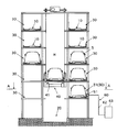
- FIG. 1 is a front view of a parking apparatus according to an embodiment of the present invention.
- FIG. 2 is a cross-sectional view of the parking apparatus according to the embodiment of the present invention taken along the line AA.
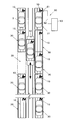
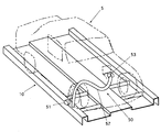
- FIG. 3 is a partial detail view of the parking apparatus according to the embodiment of the present invention.
- FIG. 4 is a functional block diagram of the parking apparatus according to the first embodiment of the present invention.
- FIG. 7 is a conceptual diagram of the parking apparatus according to the embodiment of the present invention.
- FIG. 8 is a partial detailed view of the parking apparatus according to the first embodiment of the present invention.
- the parking device is a device that parks the vehicle 5.
- FIG. 7 shows various types of parking devices such as an elevator system, an elevator slide system, a plane reciprocation system, and a transport storage system.
- the parking apparatus according to the first embodiment is an embodiment in which the present application is applied to an elevator-type parking apparatus using a pallet. For convenience of explanation, unless otherwise specified, the description will be made assuming that the left-right direction of the parked vehicle is the left-right direction of the parking device.
- the parking apparatus includes a plurality of parking spaces 30, a moving device 40, a plurality of relay circuits 50, a power feeding circuit 60, and a control device 70.
- the parking device may include a plurality of pallets 10, a plurality of parking spaces 30, a moving device 40, a plurality of relay circuits 50, a power feeding circuit 60, and a control device 70.
- the parking device may be configured by the loading / unloading station 20, the plurality of parking spaces 30, the mobile device 40, the plurality of relay circuits 50, and the power feeding circuit 60.
- the parking device may include a plurality of pallets 10, a loading / unloading station 20, a plurality of parking spaces 30, a mobile device 40, a plurality of relay circuits 50, and a power feeding circuit 60.
- the pallet 10 is a member on which the vehicle 5 can be mounted.
- the pallet is a structural member having a rectangular outline when viewed from above.
- the pallet may have a concave groove that guides a wheel parallel to the long side of the rectangle of the vehicle 5.
- the loading / unloading station 20 is a space where the vehicle is loaded or unloaded. In the case of using the pallet 10, the loading / unloading station 20 may self-propell the vehicle 5 and place it on the pallet 10 to store the vehicle 5, and self-propell the vehicle to unload it from the pallet 10 for delivery.
- a parking space 30 to be described later may also serve as the loading / unloading station 20.
- the loading / unloading station 20 may be directly loaded into a parking space 30 described later and discharged from the parking space 30.
- the parking device is an elevator system
- the loading / unloading station 20 is a space located in the lower part of the lifting / lowering space H in which the lifting / lowering device of the mobile device 40 is lifted / lowered.
- the parking space 30 is a space where each vehicle 5 can be placed.
- the parking space 30 may be a space where a plurality of pallets can be placed on each.
- the parking space 30 is a space arranged in the vertical direction in the left and right spaces of the lifting space H where the lifter 41 of the mobile device 40 is lifted and lowered.
- the parking space 30 includes a support structure that supports the pallet 10. At least one parking space 30 among the plurality of parking spaces 30 serves as a power supply parking space 31 to be described later.
- the mobile device 40 is a device that can move a vehicle from one parking space 30 of the plurality of parking spaces 30 to another parking space 30.
- the moving device 40 is a device that can move the pallet 10 between one parking space 30 and the other parking space 30 among the plurality of parking spaces 30.
- the mobile device 40 moves the vehicle 5 between the loading / unloading station 20 and one parking space 30 of the plurality of parking spaces 30 or one parking space of the plurality of parking spaces 30. This is a device that can move between 30 and another parking space 30.
- the mobile device 40 can move the pallet 10 between the loading / unloading station 20 and one parking space 30 among the plurality of parking spaces 30 or among the plurality of parking spaces 30.
- This is a device that can move the pallet 10 between one parking space 30 and another parking space 30.
- the moving device 40 is a transfer device (not shown) that is mounted on the lifter 41 that moves up and down the lifting space and that can move the pallet 10 between the lifter 41 and the parking space 30.
- the relay circuit 50 is an electric circuit that is provided so as to correspond to each vehicle and can relay power to each vehicle.
- the relay circuit 50 is a circuit that is provided on each pallet 10 and can supply power to each of the vehicles mounted on the pallet 10.
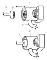
- the relay circuit 50 includes a relay terminal 51, a relay cable 52, and a relay plug 53.
- the relay terminal 51 is an electrical component that is paired with a power supply terminal 61 described later, and is supported by the pallet 10. When the relay terminal 51 and the power supply terminal 61 are fitted, the terminals are electrically joined. When the relay terminal 51 and the power supply terminal 61 are separated from each other, the terminals are separated from each other and are electrically disconnected.
- the guide portion has a trumpet shape that is provided on the power supply terminal 61 and guides the relay terminal 51.
- the guide portion guides the relay terminal 51, the relay terminal 51 and the power supply terminal 61 are fitted, and the terminals are electrically connected to each other.
- the elastic structure provided on either the relay terminal 51 or the power supply terminal 61 absorbs the mutual displacement between the relay terminal 51 and the power supply terminal 61.
- the elastic structure is a helical spring provided at the bottom of the power supply terminal 61.
- one relay terminal 51 is supported on one of the left and right sides of the pallet.
- FIG. 2 shows that one relay terminal 51 is supported on the right side of the pallet 10. In this way, when the pallet 10 is moved from the left to the right and placed in the parking space 30, the relay terminal 51 and the power supply terminal 61 are fitted.
- two relay terminals 51 are supported on the left and right sides of the pallet, respectively.
- the relay cable 52 is an electric wire cable that electrically connects the relay terminal 51 and the relay plug 53.
- the relay plug 53 is an electrical component that fits into the relay socket 6 provided in the vehicle 5 to receive power supply.
- the power supply circuit 60 supplies power to the power supply parking space 31 that is at least one of the plurality of parking spaces 30, and is provided to correspond to the vehicle 5 placed in the power supply parking space 31. This is an electric circuit that can supply power to the vehicle 5 via the circuit 50.
- the power supply circuit 60 supplies power to the power supply parking space 31, which is at least one of the plurality of parking spaces 30, and is provided on the pallet 10 placed in the power supply parking space 31. It is an electric circuit that can supply power to the vehicle via the relay circuit 50 provided.
- the power supply circuit 60 includes a power supply terminal 61, a power supply cable 62, and a power supply box 63. One power supply terminal 61 is supported by a structure constituting one power supply parking space 31.
- a plurality of power supply parking spaces 31 may be provided.
- the total number of pallets 10 may be at least one less than the total number of parking spaces 30 including the power supply parking space 31. In this way, an arbitrary pallet can be placed in the power supply parking space 31 at an arbitrary timing.
- the power supply cable 62 is an electric cable that electrically connects the power supply terminal 61 and the power supply box 63.
- the power supply box 63 is a controller that controls a power supply for supplying power to the vehicle 5. The power supply box 63 is controlled by the control device 70.
- the control device 70 is a device that controls the parking device.
- the control device 70 includes a control panel 71 and a control box 72.
- the operator operates the control panel 71.
- the control box 72 incorporates a control circuit described later.
- the control device 70 may handle a plurality of corresponding identification codes so that each of the plurality of vehicles 5 can be identified from each other.
- the control device 70 may handle a plurality of corresponding identification codes so that each of the plurality of pallets 10 can be identified from each other.
- the identification code corresponding to the pallet 10 may be the identification code of the vehicle mounted on the pallet.
- the management code recorded in the parking ticket may be used as the vehicle identification code. In this case, the management code and the pallet identification code are recorded in association with each other.
- the parking device receives a power supply reservation, which is an indication of intention to supply power to the vehicle for each vehicle, and after the vehicle 5 that has received the power supply reservation is moved from the parking space 30 to the power supply parking space 31, the power supply circuit When 60 starts feeding the vehicle 5 via the relay circuit 50 and satisfies a predetermined condition, the feeding is terminated.
- the parking device moves the vehicle 5 that has received the power supply reservation from the loading / unloading station 20 to the power supply parking space 31, and then the power supply circuit 60 starts supplying power to the vehicle 5 via the relay circuit 50 and satisfies a predetermined condition. When satisfied, power supply is terminated.
- the power supply is finished, the vehicle 5 is moved from the power supply parking space 31 to another parking space 30.
- the power feeding is finished, the vehicle 5 is moved from the power feeding parking space 31 to the loading / unloading station 20.
- the control device 70 accepts a power supply reservation, which is an indication of desire to supply power to the vehicle for each vehicle, records an identification code corresponding to the vehicle that has accepted the power supply reservation in a standby table in a write-on manner, and waits for One identification code is extracted from a plurality of identification codes recorded in the table, and after the vehicle corresponding to the extracted identification code is moved from the parking space to the feeding parking space, the feeding circuit is connected to the vehicle via the relay circuit.
- the power supply is started and the predetermined condition is satisfied, the power supply is ended, and the identification code of the vehicle that has finished the power supply is deleted from the standby table.
- each control vehicle when equipped with a loading / unloading station, each control vehicle accepts a power reservation for each vehicle that enters the loading / unloading station, indicating that it wishes to supply power to the vehicle.
- the identification code to be recorded is recorded on the standby table in a recordable manner, one identification code is extracted from among the plurality of identification codes recorded in the standby table, and the vehicle corresponding to the extracted identification code is transferred from the parking space to the power supply parking space.
- the power supply circuit starts supplying power to the vehicle via the relay circuit, and when a predetermined condition is satisfied, the power supply is terminated, and the identification code of the vehicle that has finished power supply is deleted from the standby table.
- the control device When using a pallet, the control device accepts a power supply reservation, which is an indication of desire to supply power to the vehicle for each vehicle, and waits for an identification code corresponding to the pallet on which the vehicle that has accepted the power supply reservation is mounted. Recorded on the table in a recordable manner, extracted one identification code from the multiple identification codes recorded on the standby table, and moved the pallet corresponding to the extracted identification code from the parking space to the feeding parking space before feeding.
- the circuit starts supplying power to the vehicle via the relay circuit and satisfies a predetermined condition, the power supply is terminated, and the identification code corresponding to the pallet where the power supply is stopped is deleted from the standby table.
- the control device receives a power reservation for each vehicle that has entered the loading / unloading station, indicating that it wishes to supply power to the vehicle.
- the identification code assigned to the installed pallet is recorded on the standby table in a recordable manner, one identification code is extracted from the plurality of identification codes recorded in the standby table, and the pallet corresponding to the extracted identification code is parked
- the power supply circuit starts supplying power to the vehicle via the relay circuit.
- the power supply ends and the identification code corresponding to the pallet where power supply is stopped is deleted from the standby table. To do.
- FIG. 4 shows a functional block diagram of the parking apparatus according to the embodiment of the present invention.
- the control circuit includes a CPU, a storage device, an interface, and others.
- the interface is connected to the operation panel 71, the mobile device 40, the power feeding circuit 60, and others.
- the program installed in the control circuit is a control device that has an entry reception function, a parking function, an exit reception function, a power supply reservation reception function, an identification code recording function, an identification code extraction function, a vehicle movement function, a power supply function, and an identification code deletion function. Realize other functions. Below, the case where the pallet 10 is used and a loading / unloading station is provided is demonstrated to an example.
- the intention indication that the vehicle is to be parked is received, and the vehicle 5 is received at the loading / unloading station 20.
- the moving device 40 moves the empty pallet 10 from an arbitrary parking space 30 to the loading / unloading station.
- the warehousing gate is opened, the vehicle is self-propelled and placed on the pallet 10.
- the vehicle 5 is moved from the loading / unloading station 20 to the parking space 30 using the moving device 40.
- the pallet 10 on which the vehicle 5 is placed is moved from the loading / unloading station 20 to the parking space 30 using the moving device 40.
- Power supply reservation reception function Each of them accepts a power supply reservation, which is an indication of desire to supply power to the vehicle. For each vehicle that has entered the entry / exit station, a power reservation that is an indication of desire to supply power to the vehicle may be received. Moreover, you may accept each of the power supply reservation which is an intention display of wishing to supply power to the already parked vehicle.
- the identification code corresponding to the vehicle that has accepted the power supply reservation is recorded on the standby table in a write-once manner.
- the management code recorded in the parking ticket of the vehicle that has accepted the power supply reservation is recorded on the standby table in a write-once manner as the vehicle identification code.
- an identification code corresponding to the pallet 10 on which the vehicle that has accepted the power supply reservation is mounted may be recorded on the standby table in a write-once manner.
- the identification code corresponding to the pallet on which the vehicle is mounted corresponds to the identification code corresponding to the vehicle.
- the pallet number assigned in advance to the pallet 10 on which the vehicle for which the power supply reservation has been received is mounted may be recorded on the standby table as an add-on type.
- a pallet number previously assigned to the pallet 10 on which the vehicle for which the power supply reservation has been received is mounted may be recorded on the standby table in a write-on manner as a vehicle identification code.
- One identification code is extracted from the plurality of identification codes recorded in the standby table. For example, one identification code is extracted from the plurality of identification codes recorded in the standby table in the order recorded in the order of recording.
- the vehicle corresponding to the extracted identification code is moved from the parking space 30 to the power supply parking space 31. Further, the pallet corresponding to the extracted identification code is moved from the parking space 30 to the power supply parking space 31.
- the relay terminal 51 fixed to the pallet 10 and the power supply terminal 61 fixed to the power supply parking space 31 are electrically connected. Furthermore, using the moving device 40, the powered vehicle is moved from the power supply parking space 31 to the parking space 30. Furthermore, the pallet on which the vehicle 5 that has finished power feeding is moved is moved from the power feeding parking space 31 to the parking space 30 by using the moving device 40.
- the relay terminal 51 fixed to the pallet 10 and the power supply terminal 61 fixed to the power supply parking space 31 are separated and electrically disconnected.
- the warehousing reception function, the parking function, and the warehousing reception function are sequentially repeated.
- the power supply reservation reception function, the identification code recording function, the identification code extraction function, the vehicle movement function, the power supply function, and the identification code deletion function are sequentially repeated.
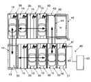
- FIG. 5 is a plan view of the parking apparatus according to the second embodiment. Description of the same points as the parking apparatus according to the first embodiment is omitted, and only different points will be described.
- the parking apparatus according to the second embodiment is an embodiment in which the invention of the present application is applied to a conventional elevator slide system and a plane reciprocation system.
- the parking device is a device that parks the vehicle 5.
- the parking device is a device that parks the vehicle 5.
- a case of a plane reciprocating parking apparatus using a pallet will be described as an example.
- the description will be made assuming that the left-right direction of the parked vehicle is the left-right direction of the parking device.
- the parking apparatus includes a plurality of parking spaces 30, a moving device 40, a plurality of relay circuits 50, a power feeding circuit 60, and a control device 70.
- the parking apparatus may include a plurality of pallets 10, a moving device 40, a plurality of relay circuits 50, a power feeding circuit 60, and a control device 70.
- the parking device may be configured by the loading / unloading station 20, the plurality of parking spaces 30, the mobile device 40, the plurality of relay circuits 50, and the power feeding circuit 60.
- the parking device may include a plurality of pallets 10, a loading / unloading station 20, a plurality of parking spaces 30, a mobile device 40, a plurality of relay circuits 50, and a power feeding circuit 60.
- the description of the pallet 10, the loading / unloading station 20, the plurality of relay circuits 50, and the power supply circuit 60 is the same as that according to the first embodiment.
- the parking space 30 is a space where each vehicle 5 can be placed.
- the parking space 30 may be a space where a plurality of pallets can be placed on each.
- the parking space 30 is a space lined up along the traveling road in the left and right spaces of the traveling road on which the horizontal traveling device 42 of the mobile device 40 described later travels.
- the parking space 30 includes a support structure that supports the pallet 10. At least one parking space 30 among the plurality of parking spaces 30 serves as a power supply parking space 31 to be described later.
- the mobile device 40 is a device that can move a vehicle from one parking space 30 of the plurality of parking spaces 30 to another parking space 30.
- the moving device 40 is a device that can move the pallet 10 between one parking space 30 and the other parking space 30 among the plurality of parking spaces 30.
- the mobile device 40 moves the vehicle 5 between the loading / unloading station 20 and one parking space 30 of the plurality of parking spaces 30 or one parking space of the plurality of parking spaces 30. This is a device that can move between 30 and another parking space 30.
- the mobile device 40 can move the pallet 10 between the loading / unloading station 20 and one parking space 30 among the plurality of parking spaces 30 or among the plurality of parking spaces 30.
- This is a device that can move the pallet 10 between one parking space 30 and another parking space 30.
- the moving device 40 is a transfer device (not shown) that can move the pallet 10 between the lid (not shown), the horizontal traveling device 42, the horizontal traveling device, and the parking space 30 that moves up and down the lifting space.
- FIG. 6 is a plan view of the parking apparatus according to the third embodiment. Description of the same points as the parking apparatus according to the first embodiment is omitted, and only different points will be described.
- the parking device according to the third embodiment is an embodiment in which the invention of the present application is applied to a conventional transportable parking device.
- the parking device is a device that parks the vehicle 5.
- the parking device is a device that parks the vehicle 5.
- an example of a transport and storage type parking apparatus using a pallet will be described.
- the description will be made assuming that the left-right direction of the parked vehicle is the left-right direction of the parking device.
- the parking apparatus includes a plurality of parking spaces 30, a moving device 40, a plurality of relay circuits 50, a power feeding circuit 60, and a control device 70.
- the parking apparatus may include a plurality of pallets 10, a moving device 40, a plurality of relay circuits 50, a power feeding circuit 60, and a control device 70.
- the parking device may be configured by the loading / unloading station 20, the plurality of parking spaces 30, the mobile device 40, the plurality of relay circuits 50, and the power feeding circuit 60.
- the parking device may include a plurality of pallets 10, a loading / unloading station 20, a plurality of parking spaces 30, a mobile device 40, a plurality of relay circuits 50, and a power feeding circuit 60.
- the description of the pallet 10, the loading / unloading station 20, the plurality of relay circuits 50, and the power supply circuit 60 is the same as that according to the first embodiment.
- the parking space 30 is a space where each vehicle 5 can be placed.
- the parking space 30 may be a space where a plurality of pallets can be placed on each.
- the parking space 30 is a space arranged in a rectangular shape on a horizontal plane along a lateral feed rail 43 and a longitudinal feed rail 44 of a mobile device described later. At least one parking space 30 among the plurality of parking spaces 30 serves as a power supply parking space 31 to be described later.
- FIG. 6 shows that the power supply parking space 31 is arranged beside the lift space H where the lifter moves up and down. Except for the pallet 10 in the power supply parking space 31, the plurality of pallets 10 circulate on the horizontal plane in the horizontal feed and the vertical feed sequentially.
- the lifter 45 moves the vehicle between a storage space (not shown) located above the elevating space H and the parking space 30. Further, the vehicle is moved from the parking space 30 to the power supply parking space 31 using the lateral feed device.
- the mobile device 40 is a device that can move a vehicle from one parking space 30 of the plurality of parking spaces 30 to another parking space 30.
- the moving device 40 is a device that can move the pallet 10 between one parking space 30 and the other parking space 30 among the plurality of parking spaces 30.
- the mobile device 40 moves the vehicle 5 between the loading / unloading station 20 and one parking space 30 of the plurality of parking spaces 30 or one parking space of the plurality of parking spaces 30. This is a device that can move between 30 and another parking space 30.
- the mobile device 40 can move the pallet 10 between the loading / unloading station 20 and one parking space 30 among the plurality of parking spaces 30 or among the plurality of parking spaces 30.
- This is a device that can move the pallet 10 between one parking space 30 and another parking space 30.
- the moving device 40 includes a pair of lateral feed rails 43, a lateral feed device (not shown), a pair of vertical feed rails 44, a vertical feed device (not shown), and a lifter 45 that moves up and down the lifting space H. Is done.
- the transverse feed device is a device that feeds a plurality of pallets 10 along the pair of transverse feed rails 43.
- the vertical feed device is a device that feeds a pair of pallets vertically along a pair of vertical feed rails 44.
- the lifter 45 is a device that places the pallet 10 that is horizontally fed and moves up and down the lifting space H to move the vehicle between the loading / unloading station 20 and the parking space 30.
- the parking device is a device that parks the vehicle 5.
- the parking device is a device that parks the vehicle 5.
- the case of an elevator type parking apparatus using a pallet will be described as an example.
- the description will be made assuming that the left-right direction of the parked vehicle is the left-right direction of the parking device.
- the parking apparatus includes a plurality of parking spaces 30, a moving device 40, a plurality of relay circuits 50, a power feeding circuit 60, and a control device 70.
- the parking apparatus may include a plurality of pallets 10, a moving device 40, a plurality of relay circuits 50, a power feeding circuit 60, and a control device 70.
- the parking device may be configured by the loading / unloading station 20, the plurality of parking spaces 30, the mobile device 40, the plurality of relay circuits 50, and the power feeding circuit 60.
- the parking device may include a plurality of pallets 10, a loading / unloading station 20, a plurality of parking spaces 30, a mobile device 40, a plurality of relay circuits 50, and a power feeding circuit 60.
- the control device accepts a power supply reservation, which is an indication of intention to supply power to the vehicle for each vehicle, records the identification code corresponding to the vehicle that has accepted the power supply reservation in a write-once form in the standby table, and stores the standby table.
- One identification code is extracted from among the plurality of identification codes recorded in.
- the delivery time of the vehicle that has accepted the power supply reservation is notified in advance and recorded in the standby table in correspondence with the identification code and the notified delivery time, and the delivery time is determined from among the plurality of identification codes recorded in the standby table.
- the identification code is extracted to give priority to the one that is approaching, and after the vehicle corresponding to the extracted identification code is moved to the feeding parking space, the feeding circuit starts feeding the vehicle via the relay circuit and the predetermined condition If the condition is satisfied, the power supply is terminated, and the identification code corresponding to the vehicle for which the power supply has been completed is deleted from the standby table.
- the control device is notified of the departure time of the vehicle that has accepted the power supply reservation, records the identification code in correspondence with the notified departure time in the standby table, and is recorded in the standby table.
- the identification code is extracted so as to give priority to the one with a short delivery time from among a plurality of identification codes, and after the pallet corresponding to the extracted identification code is moved to the power supply parking space, the power supply circuit passes through the relay circuit.
- the power supply is terminated, and the identification code corresponding to the pallet for which power supply has been completed is deleted from the standby table.
- the program installed in the control circuit is the control device, the warehousing reception function, the parking function, the warehousing reception function, the power supply reservation reception function, the identification code recording function, the evacuation time reception function, the identification code recording function, the identification code extraction function, the vehicle
- the moving function, power feeding function, identification code deleting function, and other functions are realized.
- the warehousing reception function, the parking function, the warehousing reception function, the vehicle movement function, the power supply reservation reception function, the power supply start function, the power supply end function, the identification code deletion function, and other functions are those of the parking apparatus according to the first embodiment. The same.
- the departure time of the vehicle that has accepted the power supply reservation is notified in advance, and the identification code is associated with the notified departure time and recorded in the standby table.
- Identification code extraction function One identification code is extracted from the plurality of identification codes recorded in the standby table. Furthermore, an identification code is extracted so that priority is given to the one with a short delivery time among the plurality of identification codes recorded in the standby table. For example, normally, one identification code is extracted in the order recorded in the order of recording from among the plurality of identification codes recorded in the standby table, and the time at which the delivery time approaches from among the plurality of identification codes If there is, the identification code is extracted so as to give priority to the one with a short delivery time.
- the time required for power supply is determined in advance as the time required for power supply
- the power supply start time is calculated in advance by the time required for power supply from the time of delivery
- the identification code recorded of the time of delivery is extracted. To do.
- a plurality of vehicles that have requested power supply can be parked in the power supply parking space 31 in order and can be supplied with power. Priority can be given to the vehicle in which it is.
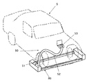
- FIG. 9 is a partial detail view of the parking apparatus according to the fifth embodiment. Description of the same points as the parking apparatus according to the first embodiment is omitted, and only different points will be described.
- the parking device is a device that parks the vehicle 5.
- the parking device is a device that parks the vehicle 5.
- the case of an elevator-type parking apparatus that does not use a pallet will be described as an example.
- the description will be made assuming that the left-right direction of the parked vehicle is the left-right direction of the parking device.
- the parking apparatus includes a plurality of parking spaces 30, a moving device 40, a plurality of relay circuits 50, a power feeding circuit 60, and a control device 70.
- the parking device may include a plurality of parking spaces 30, a mobile device 40, a plurality of relay circuits 50, a power feeding circuit 60, a control device 70, and a plurality of relay circuit fixtures 80.
- the parking apparatus may be configured by the loading / unloading station 20, the plurality of parking spaces 30, the mobile device 40, the plurality of relay circuits 50, the power feeding circuit 60, the control device 70, and the plurality of relay circuit fixtures 80.
- the configuration of the plurality of parking spaces 30, the plurality of relay circuits 50, the power feeding circuit 60, and the control device 70 is the same as that of the parking apparatus according to the first embodiment, the description thereof is omitted.
- the relay circuit fixture 80 is a device that fixes a part of the relay circuit to each.
- the relay terminal 51 of the relay circuit 50 and one end of the relay cable are fixed to the relay circuit fixture 80.
- the relay circuit fixture 80 may be detachable from the vehicle 5.
- the relay circuit fixture 80 can be attached to and detached from the wheels of the vehicle 5.
- the relay circuit fixture 80 may be positioned with respect to the vehicle 5.
- the relay circuit fixture 80 has a structure that also serves as a wheel stop for the vehicle 5.
- FIG. 9 shows an example of the relay circuit fixture 80.
- the moving device 40 is a device that can move from one parking space 30 to another parking space 30 among the plurality of parking spaces 30 by integrating the relay circuit fixture 80 and the vehicle 5 together.
- the mobile device 40 includes the relay circuit fixture 80 and the vehicle 5 as a single unit, or between the loading / unloading station 20 and one of the parking spaces 30 or a plurality of parking spaces.
- This is a device that can move between one parking space 30 of the spaces 30 and another parking space 30.
- the moving device 40 is a transfer device (not shown) that moves up and down the lifting space and is mounted on the lid 41 and the lifter 41 and can move the pallet 10 between the lifter 41 and the parking space 30. .
- the moving device 40 can support the relay circuit fixture 80 and the vehicle 5 as a single body by a skewer-like structure, and moves between the loading / unloading station 20 or the parking space 30 and the parking space 30.
- the parking space 30 can park the vehicle 5 by supporting the relay circuit fixture 80 and the vehicle 5 together by a skewer-like structure.
- the mobile device 40 can support the relay circuit fixture 80 and the vehicle 5 as a single body by a belt conveyor-like structure, and moves between the loading / unloading station 20 or the parking space 30 and the parking space 30.
- the parking space 30 can park the vehicle 5 by integrally supporting the relay circuit fixture 80 and the vehicle 5 with a belt conveyor-like structure.
- a plurality of vehicles 5 are placed in a plurality of parking spaces 30, the vehicle 5 that has received a power supply reservation is moved to the power supply parking space 31, and the power supply circuit 60 supplies power to the vehicles 5 via the relay circuit 50, satisfying predetermined conditions. Then, since power supply is terminated, while the vehicle 5 is parked in the parking space 30, the plurality of vehicles 5 that are desired to be powered are sequentially moved to the power supply parking space 31 to supply power. Since the process of returning to is repeated, the plurality of vehicles 5 can be sequentially fed.
- an identification code corresponding to the vehicle 5 that has accepted the power supply reservation is recorded in a standby table, a plurality of vehicles 5 are placed in a plurality of parking spaces 30, and a vehicle that has received a power supply reservation based on the identification code recorded in the standby table Since the power feeding circuit 60 feeds power to the vehicle via the relay circuit 50 and satisfies a predetermined condition, the power feeding is terminated and the powered vehicle is returned to the parking space 30 repeatedly. While a plurality of vehicles 5 are parked in the parking space 30, a plurality of vehicles that desire power supply can be sequentially moved to the power supply parking space to supply power.
- the vehicle 5 is received or discharged at the loading / unloading station 20, the power supply reservation of the vehicle 5 received at the storage station 20 is received, and an identification code corresponding to the vehicle 5 that has received the power supply reservation is recorded in the standby table.
- the vehicle 5 is placed in a plurality of parking spaces 30, the vehicle 5 that has received a power supply reservation based on the identification code recorded in the standby table is moved to the power supply parking space 31, and the power supply circuit supplies power to the vehicle via the relay circuit.
- the power supply is terminated, and the vehicle 5 that has been supplied with power is repeatedly returned to the parking space 30. Therefore, while the vehicle is parked in the parking space, the plurality of vehicles 5 that are desired to be powered are sequentially fed.
- Power can be moved to the parking space.
- the vehicle 5 that has been notified of the delivery time and has accepted the reservation for power supply based on the identification code recorded in the standby table is moved to the power supply parking space 31 with priority given to the time when the delivery time is approaching, and the power supply circuit is connected to the relay circuit.
- the supply of power is terminated and the vehicle 5 that has been supplied with power is repeatedly returned to the parking space 30.
- the vehicles can be sequentially moved to the power supply parking space to supply power.
- the relay circuit fixture 80 for fixing a part of the relay circuit is used so that the mobile device 40 moves the relay circuit fixture 80 and the vehicle 5 as a unit, even in a parking device that does not use a pallet.
- the power supply is terminated, and the pallet 10 on which the powered vehicle is placed is returned to the parking space 30. Since this is repeated, while the vehicle 5 is parked in the parking space 30, a plurality of vehicles for which power supply is desired can be sequentially moved to the power supply parking space to supply power.
- the vehicle is entered or exited at the entry / exit station 20, the power supply reservation of the vehicle received at the entry station 20 is received, and the identification code corresponding to the pallet 10 on which the vehicle that has received the power supply reservation is recorded is recorded in the standby table.
- the vehicle that has been notified of the departure time and has accepted the reservation for power supply based on the identification code recorded in the standby table is moved to the power supply parking space with priority given to the time of departure, and the power supply circuit passes through the relay circuit. Power is supplied to the vehicle, and when the predetermined condition is satisfied, the power supply is ended, and the pallet 10 on which the power supply has been completed is repeatedly returned to the parking space 30, so the power supply is performed while the vehicle 5 is parked in the parking space.
- a plurality of desired vehicles can be sequentially moved to the power supply parking space to supply power.
- the present invention is not limited to the embodiments described above, and various modifications can be made without departing from the scope of the invention.
- an elevator type parking apparatus has been described as an example, the present invention is not limited thereto, and the present invention can be implemented with other types of parking apparatuses.
- You may provide two or more electric power feeding parking spaces.
- some of the vehicles that request parking may make a power supply request.
- some of the vehicles that request power supply may give notice of the departure time.
- one parking space of several parking spaces may serve as the entering / exiting station.
Abstract
Description
機械式駐車装置には、垂直循環式駐車装置、エレベータ式駐車装置、地下式駐車装置、その他がある。
入出庫ステーションが、移動空間の任意の位置に設けられる。
車両は、入出庫ステーションで入出庫をする。
電気自動車は、電気をエネルギー源とする車両のひとつである。
電気自動車は、二次電池に溜めた電気を使用して走行する。
そこで、駐車中に二次電池を充電したいという要請があった。
しかし、駐車する車両の全てが電気自動車ではないし、電気自動車の一部が駐車時に給電を希望する。
また、給電に要する時間は駐車時間よりも短い場合もある。
また、給電に使用する給電回路は性能を発揮するために十分な管理が必要である。
その結果、車両を前記駐車スペースに駐車中に、給電を希望する複数の車両を順次に前記給電駐車スペースへ移動して給電できる。
上記実施形態の構成により、制御機器が、複数の車両の各々に互いを識別できる様に対応する複数の識別コードを取り扱って駐車装置を制御する。車両毎に車両への給電を希望する旨の意思表示である給電予約を各々に受け付ける。給電予約を受け付けた車両に対応する識別コードを前記待機テーブルに追記式に記録する。前記待機テーブルに記録された複数の前記識別コードのうちから一つの前記識別コードを抽出する。抽出した前記識別コードに対応する車両を前記駐車スペースから前記給電駐車スペースへ移動した後で前記給電回路が前記中継回路を介して車両に給電を開始して所定の条件を満足すると給電を終了する。給電を終了した車両の前記識別コードを前記待機テーブルから削除する。
その結果、車両を前記駐車スペースに駐車中に、給電を希望する複数の車両を順次に給電駐車スペースへ移動して給電できる。
上記実施形態の構成により、入出庫ステーションが、車両を入庫させまたは出庫させるスペースである。を備え、前記移動機器が、車両を前記入出庫ステーションと複数の前記駐車スペースのうちの一つの前記駐車スペースとの間または複数の前記駐車スペースのうちの一つの前記駐車スペースと他の一つの前記駐車スペースとの間で移動できる。前記入出庫ステーションに入庫した車両毎に車両への給電を希望する旨の意思表示である給電予約を各々に受け付ける。給電予約を受け付けた車両に対応する識別コードを前記待機テーブルに追記式に記する。前記待機テーブルに記録された複数の前記識別コードのうちから一つの前記識別コードを抽出する。抽出した識別コードに対応する車両を前記駐車スペースから前記給電駐車スペースへ移動した後で前記給電回路が前記中継回路を介して車両に給電を開始して所定の条件を満足すると給電を終了する。給電を終了した車両の前記識別コードを前記待機テーブルから削除する。
その結果、車両を前記駐車スペースに駐車中に、給電を希望する複数の車両を順次に給電駐車スペースへ移動して給電できる。
上記実施形態の構成により、前記給電予約を受け付けた車両の出庫時刻を予告されて前記識別コードと予告された前記出庫時刻とを対応させて前記待機テーブルに記録する。前記待機テーブルに記録された複数の前記識別コードのうちから前記出庫時刻の迫っているものを優先する様に前記識別コードを抽出する。抽出した前記識別コードに対応する車両を前記駐車スペースから前記給電駐車スペースへ移動した後で前記給電回路が前記中継回路を介して車両に給電を開始して所定の条件を満足すると給電を終了する。給電を終了した車両に対応する前記識別コードを前記待機テーブルから削除する。
その結果、車両を前記駐車スペースに駐車中に、給電を希望する複数の車両を出庫時刻に合わせて順次に給電駐車スペースへ移動して給電できる。
上記実施形態の構成により、複数の中継回路固定具が、複数の前記中継回路の一部を各々に固定する。前記移動機器が前記中継回路固定具と車両とを一体として複数の前記駐車スペースのうちの一つの前記駐車スペースから他の一つの前記駐車スペースに移動できる。その結果、車両を前記駐車スペースに駐車中に、給電を希望する複数の車両を順次に給電駐車スペースへ移動して給電できる。
その結果、車両を前記駐車スペースに駐車中に、給電を希望する複数の車両を順次に前記給電駐車スペースへ移動して給電できる。
上記実施形態の構成により、入出庫ステーションが、車両を前記パレットに載せて入庫しまたは前記パレットから降ろして出庫するスペースである。前記移動機器が前記パレットを前記入出庫ステーションと複数の前記駐車スペースのうちの一つの前記駐車スペースとの間または複数の駐車スペースのうちの一つの前記駐車スペースと他の一つの前記駐車スペースとの間で移動できる。前記入出庫ステーションに入庫した車両毎に車両への給電を希望する旨の意思表示である給電予約を各々に受け付ける。前記給電予約を受け付けた車両を搭載した前記パレットに付与された前記識別コードを前記待機テーブルに追記式に記録する。前記待機テーブルに記録された複数の前記識別コードのうちから一つの前記識別コードを抽出する。抽出した前記識別コードに対応する前記パレットを前記駐車スペースから前記給電駐車スペースへ移動した後で前記給電回路が前記中継回路を介して車両に給電を開始し所定の条件を満足すると給電を終了する。給電を停止した前記パレットに対応する前記識別コードを前記待機テーブルから削除する。
その結果、車両を前記駐車スペースに駐車中に、給電を希望する複数の車両を順次に給電駐車スペースへ移動して給電できる。
上記実施形態の構成により、前記給電予約を受け付けた車両の出庫時刻を予告されて前記識別コードと予告された前記出庫時刻とを対応させて前記待機テーブルに記録する。
前記待機テーブルに記録された複数の前記識別コードのうちから前記出庫時刻の迫っているものを優先する様に前記識別コードを抽出する。抽出した前記識別コードに対応する前記パレットを前記駐車スペースから前記給電駐車スペースへ移動した後で前記給電回路が前記中継回路を介して車両に給電を開始して所定の条件を満足すると給電を終了する。給電を終了した前記パレットに対応する前記識別コードを前記待機テーブルから削除する。
その結果、車両を前記駐車スペースに駐車中に、給電を希望する複数の車両を順次に給電駐車スペースへ移動して給電できる。
複数の車両を複数の駐車スペースに置き、給電予約を受け付けた車両を前記給電駐車スペースに移動し、前記給電回路が前記中継回路を介して車両に給電し、所定の条件を満足すると給電を終了するので、車両を前記駐車スペースに駐車中に、給電を希望する複数の車両を順次に前記給電駐車スペースへ移動して給電できる。
また、前記給電予約を受け付けた車両に対応する前記識別コードを前記待機テーブルに記録し、複数の車両を複数の前記駐車スペースに置き、前記待機テーブルに記録した前記識別コードを基に前記給電予約を受け付けた車両を前記駐車スペースから前記給電駐車スペースへ移動し、前記給電回路が前記中継回路を介して車両に給電し、所定の条件を満足すると給電を終了するので、車両を前記駐車スペースに駐車中に、給電を希望する複数の車両を順次に給電駐車スペースに移動して給電できる。
また、前記入出庫ステーションで車両を入庫させまたは出庫させ、前記入出庫ステーションで入庫した車両の前記給電予約を受け付け、前記給電予約を受け付けた車両に対応する前記識別コードを前記待機テーブルに記録し、複数の車両を複数の前記駐車スペースに置き、前記待機テーブルに記録した前記識別コードを基に前記給電予約を受け付けた車両を前記駐車スペースから前記給電駐車スペースへ移動し、前記給電回路が前記中継回路を介して車両へ給電し、所定の条件を満足すると給電を終了するので、車両を前記駐車スペースに駐車中に、給電を希望する複数の車両を順次に給電駐車スペースに移動して給電できる。
また、前記出庫時刻を予告され、前記待機テーブルに記録した前記識別コードを基に給電予約を受け付けた車両を出庫時刻の迫っているものを優先して前記駐車スペースから前記給電駐車スペースに移動し、前記給電回路が前記中継回路を介して車両に給電し、所定の条件を満足すると給電を終了するので、車両を前記駐車スペースに駐車中に、給電を希望する複数の車両を順次に給電駐車スペースに移動して給電できる。
また、前記中継回路の一部を固定する前記中継回路固定具を用い、前記移動機器が前記中継回路固定具と車両とを一体として移動させる様にしたので、車両を前記駐車スペースに駐車中に、給電を希望する複数の車両を順次に給電駐車スペースに移動して給電できる。
また、前記給電予約を受け付けた車両を搭載したパレットに対応する前記識別コードを前記待機テーブルに記録し、複数の車両を複数の前記駐車スペースに置き、前記待機テーブルに記録した識別コードを基に給電予約を受け付けた車両を前記駐車スペースから前記給電駐車スペースへ移動し、前記給電回路が前記中継回路を介して車両に給電し、所定の条件を満足すると給電を終了するので、車両を前記駐車スペースに駐車中に、給電を希望する複数の車両を順次に前記給電駐車スペースに移動して給電できる。
また、前記入出庫ステーションで車両を入庫させまたは出庫させ、入庫ステーションで入庫した車両の前記給電予約を受け付け、前記給電予約を受け付けた車両を載せたパレットに対応する前記識別コードを前記待機テーブルに記録し、複数の車両を複数の前記駐車スペースに置き、前記待機テーブルに記録した前記識別コードを基に給電予約を受け付けた車両を前記駐車スペースから前記給電駐車スペースへ移動し、前記給電回路が前記中継回路を介して車両へ給電し、所定の条件を満足すると給電を終了するので、車両を前記駐車スペースに駐車中に、給電を希望する複数の車両を順次に給電駐車スペースに移動して給電できる。
また、出庫時刻を予告され、前記待機テーブルに記録した前記識別コードを基に給電予約を受け付けた車両を出庫時刻の迫っているものを優先して前記駐車スペースから前記給電駐車スペースへ移動し、前記給電回路が前記中継回路を介して車両に給電し、所定の条件を満足すると給電を終了するので、車両を前記駐車スペースに駐車中に、給電を希望する複数の車両を順次に給電駐車スペースに移動して給電できる。
従って、簡易な構成で車両に給電するにに適した駐車装置を提供できる。
以下では、説明の便宜のために、後述する一対の上下移動空間を左右に配される様に見て左手の側を左側、右手の側を右側として、説明する。
図1は、本発明の実施形態に係る駐車装置の正面図である。図2は、本発明の実施形態に係る駐車装置のA-A断面図である。図3は、本発明の実施形態に係る駐車装置の部分詳細図である。図4は、本発明の第一の実施形態に係る駐車装置の機能ブロック図である。図7は、本発明の実施形態に係る駐車装置の概念図である。図8は、本発明の第一の実施形態に係る駐車装置の部分詳細図である。
図7は、エレベータ方式、エレベータ・スライド方式、平面往復方式、運搬格納方式等の、各種の方式の駐車装置を示す。
第一の実施形態にかかる駐車装置は、パレットを用いるエレベータ方式の駐車装置に本願を適用した実施形態である。
説明の便宜上、特に断らないかぎり、駐車した車両の左右方向を駐車装置の左右方向であるとして説明する。
駐車装置は、複数のパレット10と複数の駐車スペース30と移動機器40と複数の中継回路50と給電回路60と制御機器70とで構成されてもよい。
駐車装置は、入出庫ステーション20と複数の駐車スペース30と移動機器40と複数の中継回路50と給電回路60とで構成されてもよい。
駐車装置は、複数のパレット10と入出庫ステーション20と複数の駐車スペース30と移動機器40と複数の中継回路50と給電回路60とで構成されてもよい。
例えば、パレットは、上から見て長方形の輪郭をもった構造部材である。
パレットは、車両5の長方形の長辺に平行する車輪を案内する凹状の溝を持っていてもよい。
パレット10を用いる場合は、入出庫ステーション20は、車両5を自走してパレット10に載せて車両5を入庫させ、車両を自走してパレット10から降ろして出庫させてもよい。
後述する駐車スペース30が、入出庫ステーション20を兼ねていてもよい。
入出庫ステーション20を特に設けない場合に、直接に後述する駐車スペース30に入庫させ、駐車スペース30から出庫させてもよい。
例えば、駐車装置がエレベータ方式である場合に、入出庫ステーション20は、移動機器40の昇降装置の昇降する昇降空間Hの下部に位置するスペースである。
パレット10を用いる場合は、駐車スペース30は、複数のパレットを各々に置くことをできるスペースであってもよい。
駐車スペース30は、移動機器40のリフタ41の昇降する昇降空間Hの左右の空間に上下方向に並ぶスペースである。
例えば、駐車スペース30には、パレット10を支持する支持構造を備える。
複数の駐車スペース30のうちの少なくとも1つの駐車スペース30が後述する給電駐車スペース31となる。
パレット10を用いる場合は、移動機器40は、パレット10を複数の駐車スペース30のうちの一つの駐車スペース30と他の一つの駐車スペース30との間でパレット10を移動できる機器である。
入出庫ステーション20を備える場合、移動機器40は、車両5を入出庫ステーション20と複数の駐車スペース30のうちの一つの駐車スペース30との間または複数の駐車スペース30のうちの一つの駐車スペース30と他の一つの駐車スペース30との間で移動できる機器である。
入出庫ステーションを備え、パレット10を用いる場合は、移動機器40は、パレット10を入出庫ステーション20と複数の駐車スペース30のうちの一つの駐車スペース30との間または複数の駐車スペース30のうちの一つの駐車スペース30と他の一つの駐車スペース30との間でパレット10を移動できる機器である。
移動機器40は、昇降空間を昇降するリフタ41とリフタ41に搭載されリフタ41と駐車スペース30との間でパレット10を移動できる移載機器(図示せず)である。
パレット10を用いる場合は、中継回路50は、パレット10に各々に設けられパレット10に搭載された車両の各々に給電できる回路である。
例えば、中継回路50は、中継端子51と中継ケーブル52と中継プラグ53とで構成される。
中継端子51は、後述する給電端子61と対になる電気部品であり、パレット10に支持される。
中継端子51と給電端子61とが嵌合すると互いの端子を電気的に接合する。
中継端子51と給電端子61とが離間すると、互いの端子が離れ、電気的に切断される。
図3は、中継端子51と給電端子61との組合せの一例を示す。
中継端子51と給電端子61との一方が、中継端子51と給電端子61との他方を案内する案内部を設けられる。
例えば、案内部は、給電端子61に設けられ中継端子51を案内するラッパ状の形状である。
離間している中継端子51と給電端子61とが接近すると、案内部が中継端子51を案内し、中継端子51と給電端子61とが嵌合し、互いの端子が電気的に接合される。
中継端子51と給電端子61とが嵌合する際に、中継端子51と給電端子61とのどちらかに設けられた弾性構造が、中継端子51と給電端子61との互いの位置ずれを吸収する。例えば、弾性構造は、給電端子61の底部に設けられたつる巻きばねである。
パレット10が左右方向に移動して駐車スペース30に搭載される場合、1個の中継端子51がパレットの左右の一方に支持される。
図2は、1個の中継端子51がパレット10の右に支持されるのを示している。
この様にすると、パレット10を左から右に移動して駐車スペース30に置いた際に、中継端子51と給電端子61とが嵌合する。
または2個の中継端子51がパレットの左右に各々に支持される。
中継ケーブル52は中継端子51と中継プラグ53とを電気的に導通する電線ケーブルである。
中継プラグ53は給電を受け付けるため車両5に設けられた中継ソケット6に嵌合する電気部品である。
パレット10を用いる場合は、給電回路60は、複数の駐車スペース30のうちの少なくとも一つの駐車スペース30である給電駐車スペース31に電力を供給し、給電駐車スペース31に置かれたパレット10に設けられた中継回路50を介して車両に給電できる電気回路である。
給電回路60は、給電端子61と給電ケーブル62と給電ボックス63とで構成される。
ひとつの給電端子61は、ひとつの給電駐車スペース31を構成する構造に支持される。
複数の給電駐車スペース31が設けられても良い。
パレット10を用いるエレベータ方式では、パレット10の総数は、給電駐車スペース31を含む駐車スペース30の総数よりも少なくともひとつ少なくてもよい。
この様にすると、任意のパレットを任意のタイミングで給電駐車スペース31に置くことができる。
給電ケーブル62は、給電端子61と給電ボックス63とを電気的に導通する電気ケーブルである。
給電ボックス63は、車両5に給電する電源を制御するコントローラである。
給電ボックス63は、制御機器70により制御される。
制御機器70は、制御パネル71と制御ボックス72とで構成される。
オペレータは制御パネル71を操作する。
制御ボックス72は、後述する制御回路を内蔵する。
制御機器70は、複数の車両5の各々に互いを識別できる様に対応する複数の識別コードを取り扱ってもよい。
制御機器70は、複数のパレット10の各々に互いを識別できる様に対応する複数の識別コードを取り扱ってもよい。
パレット10に対応する識別コードをパレットに搭載された車両の識別コードとしてもよい。
また、駐車チケットに記録された管理コードを車両の識別コードとしてもよい。この場合に、管理コードとパレットの識別コードとを対応させて記録する。
また、駐車装置は、給電予約を受け付けた車両5を入出庫ステーション20から給電駐車スペース31へ移動した後で給電回路60が中継回路50を介して車両5に給電を開始して所定の条件を満足すると給電を終了する。
給電を終了すると、車両5を給電駐車スペース31から他の駐車スペース30へ移動する。
または、給電を終了すると、車両5を給電駐車スペース31から入出庫ステーション20へ移動する。
また、入出庫ステーションを備える場合は、制御機器が入出庫ステーションに入庫した車両毎に車両への給電を希望する旨の意思表示である給電予約を各々に受け付け、給電予約を受け付けた車両に対応する識別コードを待機テーブルに追記式に記録し、待機テーブルに記録された複数の識別コードのうちから一つの識別コードを抽出し、抽出した識別コードに対応する車両を駐車スペースから給電駐車スペースへ移動した後で給電回路が中継回路を介して車両に給電を開始して所定の条件を満足すると給電を終了し、給電を終了した車両の識別コードを待機テーブルから削除する。
また、入出庫ステーションを備える場合は、制御機器が、入出庫ステーションに入庫した車両毎に車両への給電を希望する旨の意思表示である給電予約を各々に受け付け、給電予約を受け付けた車両を搭載したパレットに付与された識別コードを待機テーブルに追記式に記録し、待機テーブルに記録された複数の識別コードのうちから一つの識別コードを抽出し、抽出した識別コードに対応するパレットを駐車スペースから給電駐車スペースへ移動した後で給電回路が中継回路を介して車両に給電を開始し所定の条件を満足すると給電を終了し、給電を停止したパレットに対応する識別コードを待機テーブルから削除する。
制御回路は、CPU、記憶装置、インターフェース、その他で構成される。
インターフェースは、操作パネル71、移動機器40、給電回路60、その他に接続される。
制御回路にインストールされるプログラムは、制御機器に、入庫受付機能、駐車機能、出庫受付機能、給電予約受付機能、識別コード記録機能、識別コード抽出機能、車両移動機能、給電機能、識別コード削除機能、その他の機能を実現させる。
以下では、パレット10を用い、入出庫ステーションを備える場合を例に説明する。
車両を駐車させたい旨の意思表示を受け付けて、車両5を入出庫ステーション20へ受け入れる。
空のパレット10が入出庫ステーション20にない場合には、移動機器40により空のパレット10を任意の駐車スペース30から入出庫ステーションへ移動する。
入庫ゲートを開けて、車両を自走させて、パレット10の上に載せる。
移動機器40を用いて、車両5を入出庫ステーション20から駐車スペース30へ移動させる。
パレットを用いる場合に、移動機器40を用いて、車両5を載せたパレット10を入出庫ステーション20から駐車スペース30へ移動させる。
車両を出庫させたい旨の意思表示を受け付ける。
移動機器40を用いて、出庫要求のあった車両を載せたパレット10を駐車スペース30から入出庫ステーション20へ移動させる。
出庫ゲートを開いて、車両を自走させて、パレット10から降ろす。
車両への給電を希望する旨の意思表示である給電予約を各々に受け付ける。
入出庫ステーションに入庫した車両毎に車両への給電を希望する旨の意思表示である給電予約を各々に受け付けてもよい。
また、既に駐車させた車両への給電を希望する旨の意思表示である給電予約を各々に受け付けてもよい。
給電予約を受け付けた車両に対応する識別コードを待機テーブルに追記式に記録する。
例えば、給電予約を受け付けた車両の駐車チケットに記録された管理コードを車両の識別コードとして待機テーブルに追記式に記録する。
パレット10を用いる場合に、給電予約を受け付けた車両を搭載したパレット10に対応する識別コードを待機テーブルに追記式に記録してもよい。この場合、車両を載せたパレットに対応する識別コードが車両に対応する識別コードに対応する。
例えば、給電予約を受け付けた車両を搭載したパレット10に予め付与されたパレット番号を識別コードとして待機テーブルに追記式に記録してもよい。
例えば、給電予約を受け付けた車両を搭載したパレット10に予め付与されたパレット番号を車両の識別コードとして待機テーブルに追記式に記録してもよい。
待機テーブルに記録された複数の識別コードのうちから一つの識別コードを抽出する。
例えば、待機テーブルに記録された複数の識別コードのうちから記録された順番に早く記録された順に一つの識別コードを抽出する。
抽出した識別コードに対応する車両を駐車スペース30から給電駐車スペース31へ移動する。
また、抽出した識別コードに対応するパレットを駐車スペース30から給電駐車スペース31へ移動する。
パレット10が給電駐車スペース31に移動すると、パレット10に固定された中継端子51と給電駐車スペース31に固定された給電端子61とが電気的に接続される。
さらに、移動機器40を用いて、給電の終了した車両を給電駐車スペース31から駐車スペース30へ移動させる。
またさらに、移動機器40を用いて、給電の終了した車両5の載ったパレットを給電駐車スペース31から駐車スペース30へ移動させる。
パレット10が給電駐車スペース31から移動すると、パレット10に固定された中継端子51と給電駐車スペース31に固定された給電端子61とが離間し電気的に切断される。
給電回路60が中継回路を介して車両に給電を開始し所定の条件を満足すると給電を終了する。
給電を停止したパレット10に対応する識別コードを待機テーブルから削除する。
給電予約受付機能と識別コード記録機能と識別コード抽出機能と車両移動機能と給電機能と識別コード削除機能とを、順次に繰り返す。
上記の機能を実施することにより、給電要求のあった複数の車両を順序良く給電駐車スペース31へ駐車させて給電させることができる。
図5は、第二の実施形態にかかる駐車装置の平面図である。
第一の実施形態にかかる駐車装置と同じ点は説明を省略し、異なる点のみを説明する。
第二の実施形態にかかる駐車装置は、従来のエレベータ・スライド方式、平面往復方式に本願の発明を適用した実施形態である。
以下では、説明の便宜上、パレットを用いる平面往復方式の駐車装置の場合を例にして説明する。
また、説明の便宜上、特に断らないかぎり、駐車した車両の左右方向を駐車装置の左右方向であるとして説明する。
駐車装置は、複数のパレット10と移動機器40と複数の中継回路50と給電回路60と制御機器70とで構成されてもよい。
駐車装置は、入出庫ステーション20と複数の駐車スペース30と移動機器40と複数の中継回路50と給電回路60とで構成されてもよい。
駐車装置は、複数のパレット10と入出庫ステーション20と複数の駐車スペース30と移動機器40と複数の中継回路50と給電回路60とで構成されてもよい。
パレット10と入出庫ステーション20と複数の中継回路50と給電回路60は、第一の実施形態にかかるものと同じなの説明を省略する。
パレット10を用いる場合は、駐車スペース30は、複数のパレットを各々に置くことをできるスペースであってもよい。
駐車スペース30は、後述する移動機器40の水平走行機器42が走行する走行路の左右の空間に走行路に沿って並ぶスペースである。
例えば、駐車スペース30には、パレット10を支持する支持構造を備える。
複数の駐車スペース30のうちの少なくとも1つの駐車スペース30が後述する給電駐車スペース31となる。
パレット10を用いる場合は、移動機器40は、パレット10を複数の駐車スペース30のうちの一つの駐車スペース30と他の一つの駐車スペース30との間でパレット10を移動できる機器である。
入出庫ステーション20を備える場合、移動機器40は、車両5を入出庫ステーション20と複数の駐車スペース30のうちの一つの駐車スペース30との間または複数の駐車スペース30のうちの一つの駐車スペース30と他の一つの駐車スペース30との間で移動できる機器である。
入出庫ステーションを備え、パレット10を用いる場合は、移動機器40は、パレット10を入出庫ステーション20と複数の駐車スペース30のうちの一つの駐車スペース30との間または複数の駐車スペース30のうちの一つの駐車スペース30と他の一つの駐車スペース30との間でパレット10を移動できる機器である。
移動機器40は、昇降空間を昇降するりフタ(図示せず)と水平走行機器42と水平走行機器と駐車スペース30との間でパレット10を移動できる移載機器(図示せず)である。
図6は、第三の実施形態にかかる駐車装置の平面図である。
第一の実施形態にかかる駐車装置と同じ点は説明を省略し、異なる点のみを説明する。
第三の実施形態にかかる駐車装置は、従来の運搬格納式の駐車装置に本願の発明を適用した実施形態である。
以下では、説明の便宜上、パレットを用いる運搬格納方式の駐車装置の場合を例にして説明する。
また、説明の便宜上、特に断らないかぎり、駐車した車両の左右方向を駐車装置の左右方向であるとして説明する。
駐車装置は、複数のパレット10と移動機器40と複数の中継回路50と給電回路60と制御機器70とで構成されてもよい。
駐車装置は、入出庫ステーション20と複数の駐車スペース30と移動機器40と複数の中継回路50と給電回路60とで構成されてもよい。
駐車装置は、複数のパレット10と入出庫ステーション20と複数の駐車スペース30と移動機器40と複数の中継回路50と給電回路60とで構成されてもよい。
パレット10と入出庫ステーション20と複数の中継回路50と給電回路60は、第一の実施形態にかかるものと同じなの説明を省略する。
パレット10を用いる場合は、駐車スペース30は、複数のパレットを各々に置くことをできるスペースであってもよい。
駐車スペース30は、後述する移動機器の横送りレール43と縦送りレール44に沿って水平面上に矩形に配置されたスペースである。
複数の駐車スペース30のうちの少なくとも1つの駐車スペース30が後述する給電駐車スペース31となる。
図6は、給電駐車スペース31がリフタの昇降する昇降空間Hの横に配置されるのを示す。
給電駐車スペース31にあるパレット10を除いて、複数のパレット10が横送りと縦送りを順次にされて水平面上を循環する。リフタ45により、昇降空間Hの上方に位置する入出庫スペース(図示せず)と駐車スペース30との間で車両を移動させる。
また、横送り機器を用いて、車両を駐車スペース30から給電駐車スペース31へ車両を移動させる。
パレット10を用いる場合は、移動機器40は、パレット10を複数の駐車スペース30のうちの一つの駐車スペース30と他の一つの駐車スペース30との間でパレット10を移動できる機器である。
入出庫ステーション20を備える場合、移動機器40は、車両5を入出庫ステーション20と複数の駐車スペース30のうちの一つの駐車スペース30との間または複数の駐車スペース30のうちの一つの駐車スペース30と他の一つの駐車スペース30との間で移動できる機器である。
入出庫ステーションを備え、パレット10を用いる場合は、移動機器40は、パレット10を入出庫ステーション20と複数の駐車スペース30のうちの一つの駐車スペース30との間または複数の駐車スペース30のうちの一つの駐車スペース30と他の一つの駐車スペース30との間でパレット10を移動できる機器である。
移動機器40は、1対の横送りレール43と横送り機器(図示せず)と1対の縦送りレール44と縦送り機器(図示せず)と昇降空間Hを昇降するリフタ45とで構成される。
横送り機器は、複数のパレット10を1対の横送りレール43に倣って横送りする機器である。
縦送り機器は、1対のパレットを1対の縦送りレール44に沿って縦送りする機器である。
りフタ45は、横送りされたパレット10を載せて昇降空間Hを昇降し、車両を入出庫ステーション20と駐車スペース30との間で移動させる機器である。
第一の実施形態にかかる駐車装置と同じ点は説明を省略し、異なる点のみを説明する。
以下では、説明の便宜上、パレットを用いるエレベータ方式の駐車装置の場合を例にして説明する。
また、説明の便宜上、特に断らないかぎり、駐車した車両の左右方向を駐車装置の左右方向であるとして説明する。
駐車装置は、複数のパレット10と移動機器40と複数の中継回路50と給電回路60と制御機器70とで構成されてもよい。
駐車装置は、入出庫ステーション20と複数の駐車スペース30と移動機器40と複数の中継回路50と給電回路60とで構成されてもよい。
駐車装置は、複数のパレット10と入出庫ステーション20と複数の駐車スペース30と移動機器40と複数の中継回路50と給電回路60とで構成されてもよい。
制御機器は、車両毎に車両への給電を希望する旨の意思表示である給電予約を各々に受け付け、給電予約を受け付けた車両に対応する識別コードを待機テーブルに追記式に記録し、待機テーブルに記録された複数の識別コードのうちから一つの識別コードを抽出する。
さらに、給電予約を受け付けた車両の出庫時刻を予告されて識別コードと予告された出庫時刻とを対応させて待機テーブルに記録し、待機テーブルに記録された複数の識別コードのうちから出庫時刻の迫っているものを優先する様に識別コードを抽出し、抽出した識別コードに対応する車両を給電駐車スペースへ移動した後で給電回路が中継回路を介して車両に給電を開始して所定の条件を満足すると給電を終了し、給電を終了した車両に対応する識別コードを待機テーブルから削除する。
また、パレットを用いる場合は、制御機器が、給電予約を受け付けた車両の出庫時刻を予告されて識別コードと予告された出庫時刻とを対応させて待機テーブルに記録し、待機テーブルに記録された複数の識別コードのうちから出庫時刻の迫っているものを優先する様に識別コードを抽出し、抽出した識別コードに対応するパレットを給電駐車スペースへ移動した後で給電回路が中継回路を介して車両に給電を開始して所定の条件を満足すると給電を終了し、給電を終了したパレットに対応する識別コードを待機テーブルから削除する。
給電予約を受け付けた車両の出庫時刻を予告されて識別コードと予告された出庫時刻とを対応させて待機テーブルに記録する。
待機テーブルに記録された複数の識別コードのうちから一つの識別コードを抽出する。
さらに、待機テーブルに記録された複数の識別コードのうちから出庫時刻の迫っているものを優先する様に識別コードを抽出する。
例えば、通常は待機テーブルに記録された複数の識別コードのうちから記録された順番に早く記録された順に一つの識別コードを抽出し、複数の識別コードのうちから出庫時刻の迫っているものがあると出庫時刻の迫っているものを優先する様に識別コードを抽出する。
例えば、給電に要する時間を給電必要時間として予め定め、出庫時刻より給電必要時間だけ事前の給電開始時刻を算出し、給電開示時刻が現在時刻に接近すると、出庫時刻の記録された識別コードを抽出する。
図9は、第五の実施形態にかかる駐車装置の部分詳細図である。
第一の実施形態にかかる駐車装置と同じ点は説明を省略し、異なる点のみを説明する。
以下では、説明の便宜上、パレットを用いないエレベータ方式の駐車装置の場合を例にして説明する。
また、説明の便宜上、特に断らないかぎり、駐車した車両の左右方向を駐車装置の左右方向であるとして説明する。
駐車装置は、複数の駐車スペース30と移動機器40と複数の中継回路50と給電回路60と制御機器70と複数の中継回路固定具80とで構成されてもよい。
駐車装置は、入出庫ステーション20と複数の駐車スペース30と移動機器40と複数の中継回路50と給電回路60と制御機器70と複数の中継回路固定具80とで構成されてもよい。
例えば、中継回路50の中継端子51と中継ケーブルの一端とが、中継回路固定具80に固定される。
中継回路固定具80は車両5に脱着可能であってもよい。
例えば、中継回路固定具80は車両5の車輪に脱着可能である。
中継回路固定具80は車両5に対して位置決めできる様になっていてもよい。
例えば、中継回路固定具80は、車両5の車輪の輪留めを兼ねる構造をもつ。
図9は、中継回路固定具80の一例を示す。
入出庫ステーション20を備える場合、移動機器40は、中継回路固定具80と車両5とを一体として入出庫ステーション20と複数の駐車スペース30のうちの一つの駐車スペース30との間または複数の駐車スペース30のうちの一つの駐車スペース30と他の一つの駐車スペース30との間で移動できる機器である。
エレベータ方式の場合は、移動機器40は、昇降空間を昇降するりフタ41とリフタ41に搭載されリフタ41と駐車スペース30との間でパレット10を移動できる移載機器(図示せず)である。
例えば、移動機器40は、串歯状の構造により、中継回路固定具80と車両5とを一体として支持でき、入出庫ステーション20または駐車スペース30と駐車スペース30との間を移動させる。駐車スペース30は、串歯状の構造により中継回路固定具80と車両5とを一体として支持して、車両5を駐車できる。
例えば、移動機器40は、ベルトコンベア状の構造により、中継回路固定具80と車両5とを一体として支持でき、入出庫ステーション20または駐車スペース30と駐車スペース30との間を移動させる。駐車スペース30は、ベルトコンベア状の構造により、中継回路固定具80と車両5とを一体として支持して、車両5を駐車できる。
複数の車両5を複数の駐車スペース30に置き、給電予約を受け付けた車両5を給電駐車スペース31に移動し、給電回路60が中継回路50を介して車両5に給電し、所定の条件を満足すると給電を終了するので、車両5を駐車スペース30に駐車中に、給電を希望する複数の車両5を順次に給電駐車スペース31へ移動して給電し、給電を終了した車両5を駐車スペース30に戻すことを繰り返すので、複数の車両5を順次に給電できる。
また、給電予約を受け付けた車両5に対応する識別コードを待機テーブルに記録し、複数の車両5を複数の駐車スペース30に置き、待機テーブルに記録した識別コードを基に給電予約を受け付けた車両を給電駐車スペース31に移動し、給電回路60が中継回路50を介して車両に給電し、所定の条件を満足すると給電を終了し、給電を終了した車両を駐車スペース30に戻すことを繰り返すので複数の車両5を駐車スペース30に駐車中に、給電を希望する複数の車両を順次に給電駐車スペースに移動して給電できる。
また、入出庫ステーション20で車両5を入庫させまたは出庫させ、入庫ステーション20で入庫した車両5の給電予約を受け付け、給電予約を受け付けた車両5に対応する識別コードを待機テーブルに記録し、複数の車両5を複数の駐車スペース30に置き、待機テーブルに記録した識別コードを基に給電予約を受け付けた車両5を給電駐車スペース31に移動し、給電回路が中継回路を介して車両へ給電し、所定の条件を満足すると給電を終了し、給電し終了した車両5を駐車スペース30へ戻すことを繰り返すので、車両を駐車スペースに駐車中に、給電を希望する複数の車両5を順次に給電駐車スペースに移動して給電できる。
また、出庫時刻を予告され、待機テーブルに記録した識別コードを基に給電予約を受け付けた車両5を出庫時刻の迫っているものを優先して給電駐車スペース31に移動し、給電回路が中継回路を介して車両に給電し、所定の条件を満足すると給電を終了し、給電を終了した車両5を駐車スペース30に戻すことを繰り返すので、車両を駐車スペースに駐車中に、給電を希望する複数の車両を順次に給電駐車スペースに移動して給電できる。
また、中継回路の一部を固定する中継回路固定具80を用い、移動機器40が中継回路固定具80と車両5とを一体として移動させる様にしたので、パレットを用いない形式の駐車装置でも、車両を駐車スペースに駐車中に、給電を希望する複数の車両を順次に給電駐車スペースに移動して給電できる。
また、中継回路固定具80を車両に脱着可能にしたので、車両と中継回路固定具80とを一体として取り扱うことを容易にできる。
また、給電予約を受け付けた車両5を搭載したパレットに対応する識別コードを待機テーブルに記録し、複数の車両を複数の駐車スペースに置き、待機テーブルに記録した識別コードを基に給電予約を受け付けた車両を給電駐車スペースに移動し、給電回路が中継回路を介して車両に給電し、所定の条件を満足すると給電を終了し、給電の終了した車両を載せたパレット10を駐車スペース30へ戻すことを繰り返すので、車両5を駐車スペース30に駐車中に、給電を希望する複数の車両を順次に給電駐車スペースに移動して給電できる。
また、入出庫ステーション20で車両を入庫させまたは出庫させ、入庫ステーション20で入庫した車両の給電予約を受け付け、給電予約を受け付けた車両を載せたパレット10に対応する識別コードを待機テーブルに記録し、複数の車両を複数の駐車スペースに置き、待機テーブルに記録した識別コードを基に給電予約を受け付けた車両を給電駐車スペース31に移動し、給電回路が中継回路を介して車両へ給電し、所定の条件を満足すると給電を終了し、給電の終了した車両を載せたパレット10を駐車スペース30へ戻すことを繰り返すので、車両5を駐車スペース30に駐車中に、給電を希望する複数の車両を順次に給電駐車スペースに移動して給電できる。
また、出庫時刻を予告され、待機テーブルに記録した識別コードを基に給電予約を受け付けた車両を出庫時刻の迫っているものを優先して給電駐車スペースに移動し、給電回路が中継回路を介して車両に給電し、所定の条件を満足すると給電を終了し、給電の終了した車両を載せたパレット10を駐車スペース30へ戻すことを繰り返すので、車両5を駐車スペースに駐車中に、給電を希望する複数の車両を順次に給電駐車スペースに移動して給電できる。
エレベータ方式の駐車装置を例に説明したがこれに限定されず、他の方式の駐車装置での本発明を実施できる。
また、ひとつの給電駐車スペースを備える場合を例に説明したがこれに限定されず、2以上の複数の給電駐車スペースを備えていてもよい。
また、駐車要求する車両のうちの幾つかの車両が給電要求をしてもよい。
また、給電要求をする車両のうちの幾つかの車両が出庫時刻を予告してもよい。
また、入出庫ステーションが複数の駐車スペースの他に設けられる例で説明したがこれに限定されず、例えば、複数の駐車スペースのうちの一つの駐車スペースが入出庫ステーションを兼ねていてもよい。
5 車両
6 中継ソケット
10 パレット
20 入出庫ステーション
30 駐車スペース
40 移動機器
41 リフタ
42 水平走行機器
43 横送りレール
44 縦送りレール
45 リフタ
50 中継回路
51 中継端子
52 中継ケーブル
53 中継プラグ
60 給電回路
61 給電端子
62 給電ケーブル
63 給電ボックス
70 制御機器
71 操作パネル
72 制御ボックス
80 中継回路固定具
Claims (6)
- 車両を駐車させる駐車装置であって、
複数の前記車両を一台毎に各々に置くことをできる複数の駐車スペースと、
車両を複数の前記駐車スペースのうちの一つの前記駐車スペースから他の一つの駐車スペースに移動できる移動機器と、
複数の車両に各々に対応する様に設けられ該車両に各々に電力を中継できる複数の中継回路と、
複数の前記駐車スペースのうちの少なくとも一つの前記駐車スペースである給電駐車スペースに電力を供給し前記給電駐車スペースに置かれた車両に対応する様に設けられた前記中継回路を介して車両に給電できる給電回路と、
を備え、
車両毎に車両への給電を希望する旨の意思表示である給電予約を各々に受けつけ、前記給電予約を受け付けた車両を前記駐車スペースから前記給電駐車スペースへ移動した後で前記給電回路が前記中継回路を介して車両に給電を開始して所定の条件を満足すると給電を終了する、
ことを特徴とする駐車装置。 - 複数の車両の各々に互いを識別できる様に対応する複数の識別コードを取り扱って駐車装置を制御する制御機器と、
を備え、
前記制御機器が、車両毎に車両への給電を希望する旨の意思表示である給電予約を各々に受けつけ、給電予約を受け付けた車両に対応する識別コードを前記待機テーブルに追記式に記録し、前記待機テーブルに記録された複数の前記識別コードのうちから一つの前記識別コードを抽出し、抽出した前記識別コードに対応する車両を前記駐車スペースから前記給電駐車スペースへ移動した後で前記給電回路が前記中継回路を介して車両に給電を開始して所定の条件を満足すると給電を終了し、給電を終了した車両の前記識別コードを前記待機テーブルから削除する、
ことを特徴とする請求項1に記載の駐車装置。 - 前記制御機器が、前記給電予約を受け付けた車両の出庫時刻を予告されて前記識別コードと予告された前記出庫時刻とを対応させて前記待機テーブルに記録し、前記待機テーブルに記録された複数の前記識別コードのうちから前記出庫時刻の迫っているものを優先する様に前記識別コードを抽出し、抽出した前記識別コードに対応する車両を前記駐車スペースから前記給電駐車スペースへ移動した後で前記給電回路が前記中継回路を介して車両に給電を開始して所定の条件を満足すると給電を終了し、給電を終了した車両に対応する前記識別コードを前記待機テーブルから削除する、
ことを特徴とする請求項2に記載の駐車装置。 - 複数の前記中継回路の一部を各々に固定する複数の中継回路固定具と、
を備え、
前記移動機器が前記中継回路固定具と車両とを一体として複数の前記駐車スペースのうちの一つの前記駐車スペースから他の一つの駐車スペースに移動できる、
ことを特徴とする請求項2に記載の駐車装置。 - 車両を駐車させる駐車装置であって、
複数の車両を各々に搭載可能な複数のパレットと、
複数のパレットを各々に置くことをできるスペースである複数の駐車スペースと、
前記パレットを複数の駐車スペースのうちの一つの前記駐車スペースと他の一つの前記駐車スペースとの間で移動できる移動機器と、
複数の前記パレットに各々に設けられ該パレットに搭載された車両の各々に電力を中継できる複数の中継回路と、
複数の前記駐車スペースのうちの少なくとも一つの前記駐車スペースである給電駐車スペースに電力を供給し前記給電駐車スペースに置かれた前記パレットに設けられた前記中継回路を介して車両に給電できる給電回路と、
複数の前記パレットの各々に互いを識別できる様に対応する複数の識別コードを取り扱って駐車装置を制御する制御機器と、
を備え、
前記制御機器が、車両毎に車両への給電を希望する旨の意思表示である給電予約を各々に受け付け、前記給電予約を受け付けた車両を搭載した前記パレットに対応する前記識別コードを前記待機テーブルに追記式に記録し、前記待機テーブルに記録された複数の前記識別コードのうちから一つの前記識別コードを抽出し、抽出した前記識別コードに対応する前記パレットを前記駐車スペースから前記給電駐車スペースへ移動した後で前記給電回路が前記中継回路を介して車両に給電を開始し所定の条件を満足すると給電を終了し、給電を停止した前記パレットに対応する前記識別コードを前記待機テーブルから削除する、
ことを特徴とする駐車装置。 - 前記制御機器が、前記給電予約を受け付けた車両の出庫時刻を予告されて前記識別コードと予告された前記出庫時刻とを対応させて前記待機テーブルに記録し、前記待機テーブルに記録された複数の前記識別コードのうちから前記出庫時刻の迫っているものを優先する様に前記識別コードを抽出し、抽出した前記識別コードに対応する前記パレットを前記駐車スペースから前記給電駐車スペースへ移動した後で前記給電回路が前記中継回路を介して車両に給電を開始して所定の条件を満足すると給電を終了し、給電を終了した前記パレットに対応する前記識別コードを前記待機テーブルから削除する、
ことを特徴とする請求項5に記載の駐車装置。
Priority Applications (4)
| Application Number | Priority Date | Filing Date | Title |
|---|---|---|---|
| SG2011047081A SG172791A1 (en) | 2008-12-26 | 2009-12-24 | Parking system |
| KR1020117017123A KR101266073B1 (ko) | 2008-12-26 | 2009-12-24 | 주차 장치 |
| EP09834926.9A EP2372046A4 (en) | 2008-12-26 | 2009-12-24 | Vehicle parking device |
| CN2009801522947A CN102264988B (zh) | 2008-12-26 | 2009-12-24 | 停车装置 |
Applications Claiming Priority (2)
| Application Number | Priority Date | Filing Date | Title |
|---|---|---|---|
| JP2008333838A JP4703716B2 (ja) | 2008-12-26 | 2008-12-26 | 駐車装置 |
| JP2008-333838 | 2008-12-26 |
Publications (1)
| Publication Number | Publication Date |
|---|---|
| WO2010074128A1 true WO2010074128A1 (ja) | 2010-07-01 |
Family
ID=42287735
Family Applications (1)
| Application Number | Title | Priority Date | Filing Date |
|---|---|---|---|
| PCT/JP2009/071404 WO2010074128A1 (ja) | 2008-12-26 | 2009-12-24 | 駐車装置 |
Country Status (6)
| Country | Link |
|---|---|
| EP (1) | EP2372046A4 (ja) |
| JP (1) | JP4703716B2 (ja) |
| KR (1) | KR101266073B1 (ja) |
| CN (1) | CN102264988B (ja) |
| SG (1) | SG172791A1 (ja) |
| WO (1) | WO2010074128A1 (ja) |
Cited By (3)
| Publication number | Priority date | Publication date | Assignee | Title |
|---|---|---|---|---|
| EP2330262A3 (de) * | 2009-12-04 | 2013-05-29 | WAP Wöhr Automatikparksysteme GmbH & Co KG | Verfahren zum Betreiben einer Parkanlage und Parkanlage |
| CN104583511A (zh) * | 2012-08-24 | 2015-04-29 | 株式会社Ihi | 移动式停车设备 |
| WO2020165446A1 (de) * | 2019-02-15 | 2020-08-20 | Hans Nussbaum | Automatisiertes parksystem für fahrzeuge |
Families Citing this family (17)
| Publication number | Priority date | Publication date | Assignee | Title |
|---|---|---|---|---|
| JP5639410B2 (ja) * | 2010-08-17 | 2014-12-10 | Ihi運搬機械株式会社 | 駐車装置 |
| JP5667902B2 (ja) * | 2011-02-09 | 2015-02-12 | Ihi運搬機械株式会社 | 駐車装置 |
| FR2981972A1 (fr) | 2011-10-26 | 2013-05-03 | Adm Concept | Installation de parcage de vehicules automobiles |
| JP6150488B2 (ja) * | 2012-10-10 | 2017-06-21 | Ihi運搬機械株式会社 | 駐車装置 |
| JP6095946B2 (ja) * | 2012-11-01 | 2017-03-15 | 三菱重工メカトロシステムズ株式会社 | 機械式駐車装置の制御装置、及びその制御方法、並びにその制御プログラム、それを備えた機械式駐車装置 |
| CN106345182B (zh) | 2013-04-15 | 2019-01-22 | 北越株式会社 | 空气过滤器用滤材、其制造方法及具备其的空气过滤器 |
| JP6359262B2 (ja) * | 2013-11-07 | 2018-07-18 | Ihi運搬機械株式会社 | 駐車装置 |
| FR3019204B1 (fr) * | 2014-03-28 | 2017-11-17 | Soletanche Freyssinet | Parking souterrain pour vehicules electriques |
| CN107599881B (zh) * | 2014-11-10 | 2020-12-04 | 青岛特来电新能源科技有限公司 | 一种立体停车场电动汽车充电系统 |
| CN104831966B (zh) * | 2015-05-13 | 2017-05-10 | 江苏谦益实业有限公司 | 一种智能悬吊式立体停车库及其工作方法 |
| CN108859802A (zh) * | 2018-04-25 | 2018-11-23 | 许继电源有限公司 | 一种基于高空桥架安装方式的电动汽车充电系统 |
| CN108819783A (zh) * | 2018-08-01 | 2018-11-16 | 安徽朗停停车科技有限公司 | 一种具有充电功能的垂直升降类立体车库 |
| ES2885190T3 (es) * | 2018-09-26 | 2021-12-13 | Siemens Ag | Dispositivo de estacionamiento para vehículos eléctricos |
| JP7353760B2 (ja) * | 2019-01-18 | 2023-10-02 | 三菱重工機械システム株式会社 | 機械式駐車装置の充電制御システム、及びその方法並びにプログラム、機械式駐車装置 |
| JP2020139298A (ja) * | 2019-02-27 | 2020-09-03 | 本田技研工業株式会社 | 車両搬送システム |
| CN110171317B (zh) * | 2019-06-14 | 2021-08-10 | 西安特锐德领充新能源科技有限公司 | 一种车辆自动充电方法及自动充电系统 |
| JP2022155684A (ja) * | 2021-03-31 | 2022-10-14 | 本田技研工業株式会社 | 搬送システム、サーバー装置及びプログラム |
Citations (5)
| Publication number | Priority date | Publication date | Assignee | Title |
|---|---|---|---|---|
| JPH0635535A (ja) | 1992-07-15 | 1994-02-10 | Meitec Corp | 屋内移動ロボット |
| JPH0916898A (ja) * | 1995-06-30 | 1997-01-17 | Toyota Motor Corp | 駐車場の予約管理装置及び予約管理方法 |
| JP2001359203A (ja) * | 2000-06-12 | 2001-12-26 | Ishikawajima Transport Machinery Co Ltd | 立体駐車場の電気自動車充電管理方法及び装置 |
| JP2003269000A (ja) * | 2002-03-13 | 2003-09-25 | Mitsubishi Heavy Ind Ltd | 駐車場および駐車場制御方法 |
| JP2003314074A (ja) * | 2002-04-25 | 2003-11-06 | Shin Meiwa Ind Co Ltd | 機械式駐車設備 |
Family Cites Families (12)
| Publication number | Priority date | Publication date | Assignee | Title |
|---|---|---|---|---|
| JP2908940B2 (ja) * | 1992-08-03 | 1999-06-23 | 日本ケーブル株式会社 | 充電装置を具えた機械式駐車装置 |
| CN2245645Y (zh) * | 1995-06-07 | 1997-01-22 | 成都川江实业开发公司 | 一种立体结构的汽车停车库 |
| JPH10153007A (ja) * | 1996-11-21 | 1998-06-09 | Shinmeiwa Eng Kk | 機械式駐車設備の遠隔制御装置 |
| TW448260B (en) * | 1997-11-06 | 2001-08-01 | Lg Ind Systems Co Ltd | Elevator type parking system |
| JPH11311037A (ja) * | 1998-04-28 | 1999-11-09 | Honda Motor Co Ltd | 車両共用システム |
| US6107942A (en) * | 1999-02-03 | 2000-08-22 | Premier Management Partners, Inc. | Parking guidance and management system |
| US6662077B2 (en) * | 1999-07-30 | 2003-12-09 | Gerhard Haag | Architecture for presenting and managing information in an automated parking and storage facility |
| CN2568766Y (zh) * | 2002-04-30 | 2003-08-27 | 冷定刚 | 直升式机械立体停车库 |
| CN1293276C (zh) * | 2004-07-19 | 2007-01-03 | 深圳职业技术学院 | 全自动立体车库 |
| CN1730869A (zh) * | 2005-09-02 | 2006-02-08 | 李泉洞 | 一种垂直升降式立体停车库 |
| JP2008199752A (ja) | 2007-02-09 | 2008-08-28 | Kyushu Electric Power Co Inc | 充電装置 |
| JP5156583B2 (ja) * | 2008-11-05 | 2013-03-06 | 新明和エンジニアリング株式会社 | 充電機能を備えた立体駐車設備 |
-
2008
- 2008-12-26 JP JP2008333838A patent/JP4703716B2/ja active Active
-
2009
- 2009-12-24 EP EP09834926.9A patent/EP2372046A4/en not_active Withdrawn
- 2009-12-24 WO PCT/JP2009/071404 patent/WO2010074128A1/ja active Application Filing
- 2009-12-24 CN CN2009801522947A patent/CN102264988B/zh active Active
- 2009-12-24 KR KR1020117017123A patent/KR101266073B1/ko active IP Right Grant
- 2009-12-24 SG SG2011047081A patent/SG172791A1/en unknown
Patent Citations (5)
| Publication number | Priority date | Publication date | Assignee | Title |
|---|---|---|---|---|
| JPH0635535A (ja) | 1992-07-15 | 1994-02-10 | Meitec Corp | 屋内移動ロボット |
| JPH0916898A (ja) * | 1995-06-30 | 1997-01-17 | Toyota Motor Corp | 駐車場の予約管理装置及び予約管理方法 |
| JP2001359203A (ja) * | 2000-06-12 | 2001-12-26 | Ishikawajima Transport Machinery Co Ltd | 立体駐車場の電気自動車充電管理方法及び装置 |
| JP2003269000A (ja) * | 2002-03-13 | 2003-09-25 | Mitsubishi Heavy Ind Ltd | 駐車場および駐車場制御方法 |
| JP2003314074A (ja) * | 2002-04-25 | 2003-11-06 | Shin Meiwa Ind Co Ltd | 機械式駐車設備 |
Non-Patent Citations (1)
| Title |
|---|
| See also references of EP2372046A4 * |
Cited By (5)
| Publication number | Priority date | Publication date | Assignee | Title |
|---|---|---|---|---|
| EP2330262A3 (de) * | 2009-12-04 | 2013-05-29 | WAP Wöhr Automatikparksysteme GmbH & Co KG | Verfahren zum Betreiben einer Parkanlage und Parkanlage |
| CN104583511A (zh) * | 2012-08-24 | 2015-04-29 | 株式会社Ihi | 移动式停车设备 |
| CN104583511B (zh) * | 2012-08-24 | 2016-12-14 | 株式会社Ihi | 移动式停车设备 |
| US9752340B2 (en) | 2012-08-24 | 2017-09-05 | Ihi Corporation | Automated parking facility |
| WO2020165446A1 (de) * | 2019-02-15 | 2020-08-20 | Hans Nussbaum | Automatisiertes parksystem für fahrzeuge |
Also Published As
| Publication number | Publication date |
|---|---|
| EP2372046A4 (en) | 2017-03-08 |
| CN102264988A (zh) | 2011-11-30 |
| KR101266073B1 (ko) | 2013-05-21 |
| JP2010156116A (ja) | 2010-07-15 |
| KR20110106404A (ko) | 2011-09-28 |
| CN102264988B (zh) | 2013-11-20 |
| JP4703716B2 (ja) | 2011-06-15 |
| SG172791A1 (en) | 2011-08-29 |
| EP2372046A1 (en) | 2011-10-05 |
Similar Documents
| Publication | Publication Date | Title |
|---|---|---|
| JP4703716B2 (ja) | 駐車装置 | |
| JP5412016B2 (ja) | 駐車装置 | |
| TW201930112A (zh) | 電動汽車的自動換電平台和換電站 | |
| TWI758067B (zh) | 電池傳輸系統及其換電站 | |
| EP0858540B1 (en) | Device for parking and retrieval of a vehicle | |
| WO2010131615A1 (ja) | 駐車装置 | |
| KR101400869B1 (ko) | 전기자동차 충전용 주차장치 | |
| JP7464544B2 (ja) | 自動倉庫システム | |
| JP5457209B2 (ja) | 駐車装置 | |
| JP2014224414A (ja) | パレットと駐車空間 | |
| KR102180875B1 (ko) | 기계식 주차장용 전기차량 충전 시스템 | |
| JP5669676B2 (ja) | 機械式駐車場の充電装置およびこれを備えた機械式駐車場 | |
| JP2014227657A (ja) | パレットと駐車空間 | |
| JP5203297B2 (ja) | 駐車装置 | |
| JP5203288B2 (ja) | 駐車装置 | |
| JP6632263B2 (ja) | 駐車装置 | |
| JP2017190600A (ja) | 駐車装置 | |
| JP6180787B2 (ja) | パレット | |
| CN114604547B (zh) | 自动仓库系统 | |
| KR102449316B1 (ko) | 주차 시스템 | |
| JP2024047293A (ja) | 機械式駐車装置 | |
| JPH11350771A (ja) | 立体駐車場 | |
| KR20240048810A (ko) | 승강식 주차시스템 | |
| JP2021085277A (ja) | 機械式駐車場 | |
| JPS6164967A (ja) | 自転車格納装置 |
Legal Events
| Date | Code | Title | Description |
|---|---|---|---|
| WWE | Wipo information: entry into national phase |
Ref document number: 200980152294.7 Country of ref document: CN |
|
| 121 | Ep: the epo has been informed by wipo that ep was designated in this application |
Ref document number: 09834926 Country of ref document: EP Kind code of ref document: A1 |
|
| NENP | Non-entry into the national phase |
Ref country code: DE |
|
| REEP | Request for entry into the european phase |
Ref document number: 2009834926 Country of ref document: EP |
|
| WWE | Wipo information: entry into national phase |
Ref document number: 4915/DELNP/2011 Country of ref document: IN Ref document number: 2009834926 Country of ref document: EP |
|
| ENP | Entry into the national phase |
Ref document number: 20117017123 Country of ref document: KR Kind code of ref document: A |