WO2010061463A1 - ドアカーテシスイッチ異常検出装置及び方法 - Google Patents
ドアカーテシスイッチ異常検出装置及び方法 Download PDFInfo
- Publication number
- WO2010061463A1 WO2010061463A1 PCT/JP2008/071574 JP2008071574W WO2010061463A1 WO 2010061463 A1 WO2010061463 A1 WO 2010061463A1 JP 2008071574 W JP2008071574 W JP 2008071574W WO 2010061463 A1 WO2010061463 A1 WO 2010061463A1
- Authority
- WO
- WIPO (PCT)
- Prior art keywords
- door
- courtesy switch
- key
- electronic key
- unlock
- Prior art date
Links
Images


Classifications
-
- G—PHYSICS
- G07—CHECKING-DEVICES
- G07C—TIME OR ATTENDANCE REGISTERS; REGISTERING OR INDICATING THE WORKING OF MACHINES; GENERATING RANDOM NUMBERS; VOTING OR LOTTERY APPARATUS; ARRANGEMENTS, SYSTEMS OR APPARATUS FOR CHECKING NOT PROVIDED FOR ELSEWHERE
- G07C9/00—Individual registration on entry or exit
- G07C9/00174—Electronically operated locks; Circuits therefor; Nonmechanical keys therefor, e.g. passive or active electrical keys or other data carriers without mechanical keys
- G07C9/00309—Electronically operated locks; Circuits therefor; Nonmechanical keys therefor, e.g. passive or active electrical keys or other data carriers without mechanical keys operated with bidirectional data transmission between data carrier and locks
-
- B—PERFORMING OPERATIONS; TRANSPORTING
- B60—VEHICLES IN GENERAL
- B60R—VEHICLES, VEHICLE FITTINGS, OR VEHICLE PARTS, NOT OTHERWISE PROVIDED FOR
- B60R25/00—Fittings or systems for preventing or indicating unauthorised use or theft of vehicles
- B60R25/20—Means to switch the anti-theft system on or off
- B60R25/24—Means to switch the anti-theft system on or off using electronic identifiers containing a code not memorised by the user
- B60R25/245—Means to switch the anti-theft system on or off using electronic identifiers containing a code not memorised by the user where the antenna reception area plays a role
-
- B—PERFORMING OPERATIONS; TRANSPORTING
- B60—VEHICLES IN GENERAL
- B60R—VEHICLES, VEHICLE FITTINGS, OR VEHICLE PARTS, NOT OTHERWISE PROVIDED FOR
- B60R25/00—Fittings or systems for preventing or indicating unauthorised use or theft of vehicles
- B60R25/20—Means to switch the anti-theft system on or off
- B60R25/24—Means to switch the anti-theft system on or off using electronic identifiers containing a code not memorised by the user
- B60R25/246—Means to switch the anti-theft system on or off using electronic identifiers containing a code not memorised by the user characterised by the challenge triggering
-
- G—PHYSICS
- G07—CHECKING-DEVICES
- G07C—TIME OR ATTENDANCE REGISTERS; REGISTERING OR INDICATING THE WORKING OF MACHINES; GENERATING RANDOM NUMBERS; VOTING OR LOTTERY APPARATUS; ARRANGEMENTS, SYSTEMS OR APPARATUS FOR CHECKING NOT PROVIDED FOR ELSEWHERE
- G07C9/00—Individual registration on entry or exit
- G07C9/00174—Electronically operated locks; Circuits therefor; Nonmechanical keys therefor, e.g. passive or active electrical keys or other data carriers without mechanical keys
- G07C2009/00753—Electronically operated locks; Circuits therefor; Nonmechanical keys therefor, e.g. passive or active electrical keys or other data carriers without mechanical keys operated by active electrical keys
- G07C2009/00769—Electronically operated locks; Circuits therefor; Nonmechanical keys therefor, e.g. passive or active electrical keys or other data carriers without mechanical keys operated by active electrical keys with data transmission performed by wireless means
- G07C2009/00793—Electronically operated locks; Circuits therefor; Nonmechanical keys therefor, e.g. passive or active electrical keys or other data carriers without mechanical keys operated by active electrical keys with data transmission performed by wireless means by Hertzian waves
-
- G—PHYSICS
- G07—CHECKING-DEVICES
- G07C—TIME OR ATTENDANCE REGISTERS; REGISTERING OR INDICATING THE WORKING OF MACHINES; GENERATING RANDOM NUMBERS; VOTING OR LOTTERY APPARATUS; ARRANGEMENTS, SYSTEMS OR APPARATUS FOR CHECKING NOT PROVIDED FOR ELSEWHERE
- G07C2209/00—Indexing scheme relating to groups G07C9/00 - G07C9/38
- G07C2209/60—Indexing scheme relating to groups G07C9/00174 - G07C9/00944
- G07C2209/63—Comprising locating means for detecting the position of the data carrier, i.e. within the vehicle or within a certain distance from the vehicle
Definitions
- the present invention relates to a door courtesy switch abnormality detection device in an in-vehicle system that forms a door unlock state based on a radio signal transmitted from an electronic key.
- door opening / closing is determined based on an on / off signal of a door courtesy switch attached to a door or the like. If this door courtesy switch abnormality (including a failure) occurs, it may cause a system malfunction using information from the door courtesy switch. Furthermore, for example, the auto-lock function causes the door to be locked with the key left in the passenger compartment. There is a risk that a key confinement state will occur.
- the auto-lock function for example, in a keyless entry system or a smart key system, when door unlocking is executed by a radio signal, the door opening / closing operation is not detected, and a predetermined time (for example, 30 seconds) elapses. This is a function that locks automatically.
- the door courtesy switch is normal, for example, the user unlocks the door and opens the door, leaves the electronic key in the passenger compartment, closes the door to return forgotten things etc., and leaves the vehicle, Although the auto-lock function does not work, if the door courtesy switch is abnormal, it is not detected that the user has opened or closed the door, so there is a possibility that a key confinement state will occur in the above situation.
- the courtesy switch is configured so that the voltage state of the wire harness connected to the courtesy switch is different between normal and abnormal, and the voltage switch is detected by detecting the voltage state of the wire harness.
- a method of detecting normality or abnormality is disclosed (for example, see Patent Document 2). JP 2004-359057 A JP 2003-297166 A
- a permanent door courtesy switch abnormality such as a wire harness disconnection or short circuit can be detected by a normal diagnostic tester.
- contact failure of the door courtesy switch is often temporary (for example, it often occurs temporarily due to hardening of the grease or biting of foreign matter at low temperatures) and is often not detected by the diagnostic tester.
- even such a temporary abnormality may cause an abnormality in the system using information from the door courtesy switch as described above, and it is useful to be detected from the viewpoint of failure analysis.
- an object of the present invention is to provide a door courtesy switch abnormality detection device and method that can accurately detect even a temporary abnormality of a door courtesy switch.
- a door courtesy switch abnormality detection device in an in-vehicle system that forms a door unlock state based on a radio signal transmitted from an electronic key, Unlock detection means for detecting the door unlock operation; Door opening / closing detection means for detecting the opening / closing operation of the door based on an on / off signal from the door courtesy switch; When a door unlocking operation is detected by the information generating unit that generates information indicating an abnormality of the door courtesy switch and the unlock detecting unit, the door opening / closing detecting unit does not detect the door opening operation.
- An unlock time key determination means for determining whether or not the electronic key is present in the passenger compartment based on the reception status of the radio wave transmitted from the electronic key,
- the information generation means generates information indicating an abnormality of the door courtesy switch when the unlocking key determination means determines that an electronic key is present in the vehicle interior, the door courtesy switch abnormality detection device Is provided.
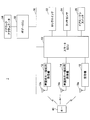
- FIG. 1 is a configuration diagram of an entire system in which an example of a door courtesy switch abnormality detection device 1 according to the present invention is incorporated. It is a figure which shows an example of the lock switch 22 and the touch sensor 24. FIG. It is a figure which shows an example of the detection area etc. of the antenna 14a for vehicle interior key detection. It is a flowchart which shows an example of the abnormality detection process of the door courtesy switch 26 performed in cooperation by smart ECU10 and body ECU32. 7 is a flowchart illustrating another example of an abnormality detection process of the door courtesy switch 26 that is executed in cooperation with the smart ECU 10 and the body ECU 32.
- FIG. 10 is a flowchart showing still another example of an abnormality detection process for the door courtesy switch 26 executed in cooperation with the smart ECU 10 and the body ECU 32. It is a flowchart which shows an example of the suitable pre-processing at the time of performing the abnormality detection process of the door courtesy switch 26 by a present Example.
- Door courtesy switch abnormality detection device 10 Smart ECU DESCRIPTION OF SYMBOLS 12 Outside key detection transmitter 12a Outside key detection antenna 14 Inside key detection transmitter 14a Inside key detection antenna 18 Receiver 22 Lock switch 24 Touch sensor 26 Door courtesy switch 30 Bidirectional multiplex communication line 32 Body ECU 34 Door lock actuator 40 Electronic key
- FIG. 1 is a configuration diagram of an entire system in which an example of a door courtesy switch abnormality detection device 1 according to the present invention is incorporated.
- the door courtesy switch abnormality detection device 1 is mainly composed of a smart ECU 10 that controls a smart key system and a body ECU 32.
- Each of the smart ECU 10 and the body ECU 32 is configured as a microcomputer including a CPU, a ROM, a RAM, and the like that are connected to each other via a bus (not shown).
- Various programs executed by the CPU are stored in the ROM.
- the smart ECU 10 is connected to a door courtesy switch 26.
- the door courtesy switch 26 is disposed corresponding to each door (which may include a luggage door) of the vehicle.
- the output signal of each door courtesy switch 26 is supplied to the smart ECU 10.
- the door courtesy switch 26 is turned on when the door is open and turned off when the door is closed.
- the door courtesy switch 26 may be turned off when the door is open and turned on when the door is closed.
- the door courtesy switch 26 may be attached to, for example, a door or a body, or may be a type of switch built in the door lock actuator 34.
- the door courtesy switch 26 may be a switch of a type in which an electrical contact is turned on / off in a mechanical manner when the door is opened or closed, or based on another detection principle (for example, an optical detection principle). There may be.
- the smart ECU 10 is connected to a vehicle exterior key detection transmitter 12 that forms a detection area for detecting the electronic key 40 outside the vehicle interior.
- the vehicle exterior key detection transmitter 12 includes a vehicle exterior key detection antenna 12a, and forms a detection region for detecting the electronic key 40 by transmitting a request signal via the vehicle exterior key detection antenna 12a.
- the range in which the request signal transmitted from the vehicle interior key detection antenna 12a can be normally received by the electronic key 40 is the vehicle exterior key detection transmitter 12 (the vehicle exterior key detection antenna 12a. ) Detection area.
- a plurality of vehicle exterior key detection transmitters 12 and vehicle exterior key detection antennas 12a may be set. For example, the right and left side door exterior spaces and the front passenger side door exterior spaces of the vehicle One each may be built in the door outside handle.
- the smart ECU 10 is connected to a vehicle interior key detection transmitter 14 that forms a detection area for detecting the electronic key 40 in the vehicle interior.
- the vehicle interior key detection transmitter 14 includes a vehicle interior key detection antenna 14a, and forms a detection region for detecting the electronic key 40 by transmitting a request signal via the vehicle interior key detection antenna 14a.
- the range in which the request signal transmitted from the vehicle interior key detection antenna 14a can be normally received by the electronic key 40 is the vehicle interior key detection transmitter 14 (vehicle interior key detection antenna 14a). ) Detection area.
- a plurality of vehicle interior key detection transmitters 14 and vehicle interior key detection antennas 14a may be set, for example, a total of three corresponding to the front seat space, rear seat space, and luggage space of the vehicle. May be.
- the smart ECU 10 is connected to a receiver 18 that receives a response signal (transmitted radio wave) from the electronic key 40.
- the receiver 18 is arranged at a position that can receive a response signal transmitted from the electronic key 40 in the detection area of the vehicle interior key detection antenna 12a and the vehicle interior key detection antenna 14a. May be arranged.
- the receiver 18 may be additionally arranged in the luggage space, and the number and arrangement position thereof are arbitrary.
- the receiver 18 When receiving the response signal from the electronic key 40, the receiver 18 performs predetermined processing such as amplification and demodulation on the response signal received from the electronic key 40, and then supplies the demodulated response signal to the smart ECU 10. To do.
- the smart ECU 10 compares the encryption code included in the received response signal with the encryption code stored in a predetermined memory (not shown), and if they match, the smart ECU 10 is the authorized electronic key 40. Authentication result (authentication result that key authentication has been obtained) is output.
- the electronic key 40 includes a transmitter / receiver (transponder) that performs bidirectional communication with a vehicle-side transmitter / receiver (elements 12, 14, 18, etc.) using weak radio waves, and a transmission / reception antenna.
- a memory for storing a given valid encryption code (ID code) is incorporated.
- the electronic key 40 includes a switch (button) that can be operated by the user, and transmits a wireless signal instructing door locking / unlocking according to the operation of the switch (that is, a function of a normal keyless entry system). May be provided.
- the electronic key 40 may be a mechanical key built-in key including a mechanical key that can lock and unlock the door of the vehicle by a user operation.
- the electronic key 40 may be a key independent of the mechanical key.
- the electronic key 40 When the electronic key 40 receives the request signal transmitted via the vehicle compartment key detection antenna 12a as described above, the electronic key 40 transmits a response signal corresponding to the request signal. In this response signal, a code indicating that the response is a response to the outside key detection antenna 12a is incorporated together with the encryption code. Further, when the electronic key 40 receives a request signal transmitted via the vehicle interior key detecting antenna 14a as described above, the electronic key 40 transmits a response signal corresponding to the request signal. In this response signal, a code representing a response to the vehicle interior key detecting antenna 14a is incorporated together with the encryption code. Thus, the electronic key 40 receives the request signal transmitted via the vehicle interior key detection antenna 12a and the request signal transmitted via the vehicle interior key detection antenna 14a as described above. Different response signals are transmitted when they are received. Thereby, smart ECU10 can grasp
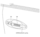
- a lock switch 22 Connected to the smart ECU 10 are a lock switch 22 that is turned on / off in response to a lock operation for locking the door, and a touch sensor 24 for detecting a touch operation on the door outside handle.
- the lock switch 22 and the touch sensor 24 are provided in the vicinity of the door outside handle, and the touch sensor 24 may be arranged to detect a touch operation on the back side of the door outside handle. .
- a body ECU 32 is connected to the smart ECU 10 via a bidirectional multiplex communication line 30.
- a door lock actuator 34 that drives a door lock mechanism is connected to the body ECU 32.
- the door lock actuator 34 switches the door lock mechanism between a door locked state and a door unlocked state in accordance with a control signal from the body ECU 32.
- the smart ECU 10 makes a request through the vehicle exterior key detection transmitter 12 and the vehicle exterior key detection antenna 12a so that a predetermined detection area is formed outside the vehicle interior. Send a signal.
- This predetermined detection area may be an area indicated by X2, for example, as shown in FIG.
- a response signal is received from the electronic key 40 by the receiver 18.
- the smart ECU 10 collates the ID code included in the response signal received by the receiver 18 with the ID code set and stored in advance, thereby approaching the vehicle with the electronic key 40 having a valid ID code. To detect.
- the body ECU 32 detects a predetermined operation intended to open the door by the user (for example, the touch sensor 24 detects contact or proximity of the user's hand to the door outer handle). At the same time, an unlocking drive signal is supplied to the door lock actuator 34 of the corresponding door locking mechanism. As a result, the door unlocked state is formed, and the user who has the valid electronic key 40 opens the desired door without taking out the electronic key 40 and inserting it into the key cylinder or operating the switch of the electronic key 40. You can get into the car.
- the unlocking operation realized using the smart key system in this manner is also referred to as “smart unlocking”.
- unlocking operation realized using a normal keyless entry system is also referred to as “wireless unlocking”.
- unlock operations other than smart unlock and wireless unlock typically include key-linked unlock realized by the user inserting the electronic key 40 into the door key cylinder and turning it.
- the smart ECU 10 detects a door opening operation by the user after smart unlocking (or wireless unlocking) (when the door courtesy switch 26 is turned on), a predetermined detection area is formed in the vehicle interior.
- the request signal is transmitted via the vehicle interior key detection transmitter 14 and the vehicle interior key detection antenna 14a.
- the predetermined detection area is, for example, as shown in FIG. 3, an area where the user carrying the electronic key 40 can usually exist or an area where the user can usually place the electronic key 40 (as indicated by Y1). The area may cover the area.
- the electronic key 40 in the predetermined detection area transmits a response signal in response to the request signal, and the response signal is received by the receiver 18.
- the smart ECU 10 determines that the electronic key 40 (authorized user) exists in the vehicle interior.
- the immobilizer function is released and the steering lock is released, and the engine can be started by an engine switch (not shown).
- the process for detecting the presence of the electronic key 40 in the vehicle interior is also referred to as “normal vehicle interior key collation process” in order to distinguish it from the same process as described later.
- the release of the immobilizer function, the unlocking of the steering lock, and the like may be realized directly in conjunction with the courtesy switch 14 being turned on from off without passing through the normal vehicle interior key collation process.
- the smart ECU 10 detects a pressing operation of the lock switch 22 disposed on the door outer handle. When the pressing operation of the lock switch 22 is detected, the smart ECU 10 makes a request through the vehicle exterior key detection transmitter 12 and the vehicle exterior key detection antenna 12a so that a predetermined detection area is formed outside the vehicle interior. Send a signal.
- This predetermined detection area may be an area indicated by X2, for example, as shown in FIG.
- a response signal is received from the electronic key 40 by the receiver 18.
- the smart ECU 10 checks the ID code included in the response signal received by the receiver 18 with the ID code that is set and stored in advance, so that the electronic key 40 having a valid ID code is taken out of the vehicle. To detect.
- the body ECU 32 supplies a locking drive signal to the door lock actuator 34 of the unlocked door lock mechanism.
- the door lock state is formed, and the user who has the valid electronic key 40 can lock the door without taking out the electronic key 40 and inserting it into the key cylinder or operating the switch of the electronic key 40. it can.
- the lock operation realized using the smart key system in this way is also referred to as “smart lock”.
- a lock operation realized by using a normal keyless entry system (lock command by switch operation) is also referred to as “wireless lock”.
- the lock operation other than the smart lock and the wireless lock typically includes a key interlocking lock realized by the user inserting and turning the electronic key 40 into the door key cylinder.
- FIG. 4 is a flowchart showing an example of an abnormality detection process of the door courtesy switch 26 that is executed in cooperation with the smart ECU 10 and the body ECU 32.
- the processing routine shown in FIG. 4 may be started when a door unlocking operation occurs.
- the process of the step in which the subject is not specified among the following steps may be executed by either one of the smart ECU 10 and the body ECU 32, or may be executed in cooperation with both. Good.
- step 400 it is determined whether the door unlocking operation is smart unlocking or wireless unlocking (that is, whether the door unlocking operation is realized by a radio signal other than key interlock unlocking). If the door unlocking operation is smart unlocking or wireless unlocking, the process proceeds to step 402. In other cases (such as key interlock unlocking), the door courtesy switch is used during the current door unlocking operation. Since 26 abnormalities cannot be detected with high accuracy, the processing is terminated.
- step 402 it is determined whether or not the door has been opened, that is, whether or not the door courtesy switch 26 has been turned on. If the door courtesy switch 26 is turned on from off, it is determined that there is no abnormality in the door courtesy switch 26 and the process ends. On the other hand, if the door courtesy switch 26 does not turn on from OFF, the routine proceeds to step 404. In this step 402, when the door courtesy switch 26 does not turn on from off within a predetermined time after the door unlocking operation, the routine may proceed to step 404.
- the predetermined time may be a time corresponding to a normal time from the door unlocking operation until the user opens the door. In the case of wireless unlocking, the predetermined time is longer than that in the case of smart locking. Also good.
- step 404 vehicle interior key verification is executed. Specifically, the smart ECU 10 transmits a request signal via the vehicle interior key detection transmitter 14 and the vehicle interior key detection antenna 14a so that a predetermined detection area is formed in the vehicle interior.
- the predetermined detection area is, for example, as shown in FIG. 3, an area where the user carrying the electronic key 40 can usually exist or an area where the user can usually place the electronic key 40 (as indicated by Y1). The area may cover the area. However, the predetermined detection area may be larger or smaller than the predetermined detection area during the normal vehicle interior key matching process.
- step 406 the smart ECU 10 determines whether or not the electronic key 40 is present in the passenger compartment.
- the electronic key 40 is present in the predetermined detection area Y1 (that is, when the user is present in the passenger compartment)
- a response signal is transmitted in response to the request signal, and this response signal is received by the receiver 18.
- the smart ECU 10 may determine whether or not the electronic key 40 exists in the vehicle interior based on whether or not a response signal is received from the electronic key 40.
- the smart ECU 10 determines that the electronic key 40 exists in the passenger compartment when the response signal is received by the receiver 18 and the key authentication is obtained (the encryption code matches), and either of them is not satisfied. In this case, it may be determined that the electronic key 40 does not exist in the vehicle interior. In any case, if it is determined that the electronic key 40 is present in the passenger compartment, the process proceeds to step 408, and if it is determined that the electronic key 40 is not present in the passenger compartment, it is determined that there is no abnormality in the door courtesy switch 26. , It ends as it is.
- step 408 it is determined that the door courtesy switch 26 has an abnormality. This is because a situation in which the electronic key 40 is present in the passenger compartment despite the fact that the door opening operation is not performed cannot occur originally, and the door courtesy switch 26 is abnormal (that is, the door courtesy switch 26 is turned on). This is because it can be determined that there is a high possibility that there is an abnormality that does not turn on when it should be. In this case, a signal (diagnosis) indicating an abnormality of the door courtesy switch 26 may be generated. This signal may include additional information such as an abnormality occurrence time.
- various determination processes for example, a normal vehicle interior key collation process for releasing the immobilizer function
- the activation condition may be temporarily corrected so that the activation is performed even when the switch 26 is not turned on.
- the electronic key 40 does not appear in the passenger compartment without detecting the opening operation of the door in the situation where the door courtesy switch 26 is normal.
- an abnormality of the door courtesy switch 26 is detected.
- a permanent (trendous) abnormality of the door courtesy switch 26 but also a temporary abnormality of the door courtesy switch 26 (for example, an abnormality which temporarily occurs due to hardening of grease or biting of foreign matter at a low temperature). Even so, it can be detected with high accuracy.
- FIG. 5 is a flowchart showing another example of the abnormality detection process of the door courtesy switch 26 executed in cooperation with the smart ECU 10 and the body ECU 32.
- the processing routine shown in FIG. 5 is started when a door unlocking operation occurs, and may be repeatedly executed at predetermined intervals.
- the process of the step in which the subject is not particularly specified may be executed by either the smart ECU 10 or the body ECU 32, or may be executed in cooperation with both.
- step 506 if it is determined in step 506 that the electronic key 40 does not exist in the vehicle interior, the process proceeds to step 509.
- step 509 it is determined whether or not the auto-lock function has been activated.
- the auto-lock function refers to the case where there is an unlocking operation (for example, an operation of the touch sensor 24) with the key authentication of the electronic key 40 being released and the door lock is released, but thereafter there is no door opening operation within a predetermined time ⁇ T.
- the predetermined time ⁇ T is typically determined from the viewpoint of both crime prevention and convenience, but may be a fixed value such as 30 seconds, or may be a variable value selected by the user. Good.
- step 509 when it is determined that the electronic key 40 is not present in the vehicle interior and the auto-lock function is activated, that is, after the door unlocking operation (after smart unlocking or wireless unlocking), the predetermined time ⁇ T has elapsed. In that case, it is determined that there is no abnormality in the door courtesy switch 26, and the process ends. Such a situation is assumed, for example, when a user outside the vehicle accidentally operates the switch of the electronic key 40 (without noticing) and performs wireless unlocking.
- the auto-lock function when the auto-lock function is not activated, that is, when the predetermined time ⁇ T has not yet elapsed after the door unlocking operation, the process returns to step 502 for the next cycle.
- the operation of the auto-lock function may be delayed (that is, the predetermined time ⁇ T may be extended). Good). Accordingly, there is a high possibility that the user is not automatically locked when the user returns to the vehicle by the extended amount, so that the possibility of avoiding key confinement due to the abnormality of the door courtesy switch 26 is increased.
- the extension amount of the predetermined time ⁇ T is set to an appropriate length so as not to greatly impair crime prevention (for example, within a range of 30 seconds to 5 minutes).
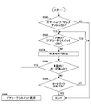
- FIG. 6 is a flowchart showing still another example of the abnormality detection process of the door courtesy switch 26 that is executed in cooperation with the smart ECU 10 and the body ECU 32.
- the processing routine shown in FIG. 6 is started when a door unlocking operation occurs, and may be repeatedly executed at predetermined intervals.
- the process of the step in which the subject is not particularly specified may be executed by either the smart ECU 10 or the body ECU 32, or may be executed in cooperation with both.
- steps 600 to 606 shown in FIG. 6 is the same as the processing in steps 400 to 406 shown in FIG. 4, and the processing in step 609 shown in FIG. 6 is the same as the processing in step 509 shown in FIG. Yes, the description is omitted.
- step 606 if it is determined in step 606 that the electronic key 40 exists in the vehicle interior, the process proceeds to step 610, and if it is determined that the electronic key 40 does not exist in the vehicle interior, the process proceeds to step 609. .
- step 610 the courtesy switch abnormality counter F is incremented by one.
- the initial value of the courtesy switch abnormality counter may be zero.
- step 612 it is determined whether the courtesy switch abnormality counter F has reached a predetermined value N or not.
- the process proceeds to step 614.
- the courtesy switch abnormality counter F is less than the predetermined value N, the process returns to step 602.
- step 614 an abnormality of the door courtesy switch 26 is determined.
- the courtesy switch diagnosis is turned on and a time stamp is given. This facilitates later failure analysis.
- the time limit is added to this logic and the courtesy switch abnormality counter F becomes N or more times within a certain period, it is regarded as a trending abnormality or a sign of failure (a kind of abnormality) and less than N times. In some cases, it is possible to divide the diagnosis and output it, such as considering it as a temporary abnormality.
- FIG. 7 is a flowchart showing an example of a suitable preprocess when performing the abnormality detection process (the process of FIGS. 4 to 6) of the door courtesy switch 26 according to the present embodiment.
- the process shown in FIG. 7 is a process for detecting a door lock state in which the electronic key 40 does not exist in the vehicle interior.
- the processing routine shown in FIG. 7 may be started when a door lock operation occurs.
- the process of the step in which the subject is not particularly specified may be executed by either the smart ECU 10 or the body ECU 32, or may be executed in cooperation with both.
- step 700 it is determined whether or not the door lock operation is a smart lock. If the door lock operation is smart lock, it can be determined that the electronic key 40 does not exist in the vehicle interior (that is, the electronic key 40 exists outside the vehicle), so the process proceeds to step 708, and otherwise (key interlocking lock). Or in the case of a wireless lock), the process proceeds to step 702.
- step 702 it is determined whether the door lock operation is a key interlock lock or a wireless lock. If the door lock operation is a key interlock lock or a wireless lock, the process proceeds to step 704. In other cases (for example, this is realized by operating the lock switch in the vehicle interior by reaching into the vehicle interior from an open window). In the case of a door lock operation or the like), the door lock state in which the electronic key 40 does not exist in the vehicle interior cannot be accurately detected, and thus the process is terminated.
- step 704 vehicle interior key verification is executed. Specifically, the smart ECU 10 transmits a request signal via the vehicle interior key detection transmitter 14 and the vehicle interior key detection antenna 14a so that a predetermined detection area is formed in the vehicle interior.
- the predetermined detection area is, for example, as shown in FIG. 3, an area where the user carrying the electronic key 40 can usually exist or an area where the user can usually place the electronic key 40 (as indicated by Y1). The area may cover the area. However, the predetermined detection area may be larger or smaller than the predetermined detection area during the normal vehicle interior key matching process.
- step 706 the smart ECU 10 determines whether or not the electronic key 40 exists in the vehicle interior.
- the electronic key 40 is present in the predetermined detection area Y1 (that is, when the user is present in the passenger compartment)
- a response signal is transmitted in response to the request signal, and this response signal is received by the receiver 18.
- the smart ECU 10 may determine whether or not the electronic key 40 exists in the vehicle interior based on whether or not a response signal is received from the electronic key 40.
- the smart ECU 10 determines that the electronic key 40 exists in the passenger compartment when the response signal is received by the receiver 18 and the key authentication is obtained (the encryption code matches), and either of them is not satisfied. In this case, it may be determined that the electronic key 40 does not exist in the vehicle interior. In any case, if it is determined that the electronic key 40 does not exist in the vehicle interior, the process proceeds to step 708. On the other hand, if it is determined that the electronic key 40 exists in the vehicle interior, the door where the electronic key 40 does not exist in the vehicle interior. It is determined that the lock is not established, and the process ends as it is.
- step 708 the smart ECU 10 determines that the electronic key 40 does not exist in the passenger compartment, and a flag (key absence flag) indicating that is set.
- the key absence flag is lowered, for example, when a door lock operation is subsequently detected.
- the abnormality detection process (the process of FIGS. 4 to 6) of the door courtesy switch 26 according to the present embodiment is configured to be activated only when a door lock operation is detected with the key absent flag set. .
- the door lock state can be formed while the electronic key 40 is placed in the vehicle interior. Therefore, when the door lock state is formed, the door courtesy switch described above is used. If the abnormality detection process 26 is performed, an abnormality of the door courtesy switch 26 may be erroneously detected. Accordingly, the logic shown in FIG. 7 is added, and the above-described abnormality detection process of the door courtesy switch 26 is performed only when it is detected that a door lock state in which the electronic key 40 does not exist in the vehicle interior is formed. Thus, the abnormality detection accuracy of the door courtesy switch 26 can be increased.
- the door courtesy switch 26 does not clearly indicate which door courtesy switch 26 of the door courtesy switches 26 provided in each door and luggage door, but in the above description, the door courtesy switch 26 refers to Any one or a predetermined one of door courtesy switches 26 provided on each door excluding the luggage door may be used, or any one of the door courtesy switches 26 provided on each door and the luggage door respectively. Or a predetermined one.
- the two ECUs of the smart ECU 10 and the body ECU 32 are used.
- other ECUs may realize a part of the functions of the smart ECU 10 and the body ECU 32 described above.
- the function of the body ECU 32 may be realized by one ECU.
- the functions of the smart ECU 10 and the body ECU 32 described above are examples, and one function may be realized by the other.
Abstract
Description
ドアアンロック動作を検出するアンロック検出手段と、
ドアカーテシスイッチからのオン/オフ信号に基づいて、ドアの開閉動作を検出するドア開閉検出手段と、
前記ドアカーテシスイッチの異常を表す情報を生成する情報生成手段と
前記アンロック検出手段によりドアアンロック動作が検出された場合に、前記ドア開閉検出手段によりドアの開動作が検出されていない状況下で、電子キーから発信される電波の受信状況に基づいて、車室内に電子キーが存在するか否かを判定するアンロック時キー判定手段とを備え、
前記情報生成手段は、前記アンロック時キー判定手段により車室内に電子キーが存在すると判定された場合に、前記ドアカーテシスイッチの異常を表す情報を生成することを特徴とする、ドアカーテシスイッチ異常検出装置が提供される。
10 スマートECU
12 車室外キー検知用発信機
12a 車室外キー検知用アンテナ
14 車室内キー検知用発信機
14a 車室内キー検知用アンテナ
18 受信機
22 ロックスイッチ
24 タッチセンサ
26 ドアカーテシスイッチ
30 双方向多重通信線
32 ボデーECU
34 ドアロックアクチュエータ
40 電子キー
スマートECU10は、所定の車両の駐車状態が検出されると、車室外に所定の検知領域が形成されるように、車室外キー検知用発信機12及び車室外キー検知用アンテナ12aを介してリクエスト信号を送信する。この所定の検知領域は、例えば図3に示すように、X2で指示されるような領域であってよい。検知領域内に電子キー40が存在すると、電子キー40から応答信号が受信機18にて受信される。スマートECU10は、受信機18で受信された応答信号に含まれるIDコードと予め設定・記憶されているIDコードとを照合することで、正当なIDコードを備える電子キー40の車両への接近を検出する。IDコードの照合が確認されると、ボデーECU32は、ユーザによるドアの開操作を意図する所定の操作の検出(例えば、ドアアウターハンドルへのユーザの手の接触ないし近接をタッチセンサ24により検出)と同時に、対応するドアのロック機構のドアロックアクチュエータ34に対して解錠用の駆動信号を供給する。この結果、ドアアンロック状態が形成され、正当な電子キー40を所持するユーザは、電子キー40を取り出してキーシリンダーに挿入し若しくは電子キー40のスイッチを操作することなく、所望のドアを開けて車内に乗り込むことができる。以下、このようにしてスマートキーシステムを利用して実現されるアンロック動作を、「スマートアンロック」ともいう。他方、通常のキーレスエントリシステム(スイッチ操作によるアンロック指令)を利用して実現されるアンロック動作を、「ワイヤレスアンロック」ともいう。尚、スマートアンロック及びワイヤレスアンロック以外のアンロック動作は、典型的には、ユーザが電子キー40をドアキーシリンダに差し込んで回すことで実現されるキー連動アンロックを含む。
スマートECU10は、ドアアウターハンドルに配設されたロックスイッチ22の押圧操作を検出する。ロックスイッチ22の押圧操作が検出されると、スマートECU10は、車室外に所定の検知領域が形成されるように、車室外キー検知用発信機12及び車室外キー検知用アンテナ12aを介してリクエスト信号を送信する。この所定の検知領域は、例えば図3に示すように、X2で指示されるような領域であってよい。検知領域内に電子キー40が存在すると、電子キー40から応答信号が受信機18にて受信される。スマートECU10は、受信機18で受信された応答信号に含まれるIDコードと予め設定・記憶されているIDコードとを照合することで、正当なIDコードを備える電子キー40の車外への持ち出しを検出する。IDコードの照合が確認されると、ボデーECU32は、アンロック状態のドアロック機構のドアロックアクチュエータ34に対して施錠用の駆動信号を供給する。この結果、ドアロック状態が形成され、正当な電子キー40を所持するユーザは、電子キー40を取り出してキーシリンダーに挿入し若しくは電子キー40のスイッチを操作することなく、ドアを施錠することができる。以下、このようにしてスマートキーシステムを利用して実現されるロック動作を、「スマートロック」ともいう。他方、通常のキーレスエントリシステム(スイッチ操作によるロック指令)を利用して実現されるロック動作を、「ワイヤレスロック」ともいう。尚、スマートロック及びワイヤレスロック以外のロック動作は、典型的には、ユーザが電子キー40をドアキーシリンダに差し込んで回すことで実現されるキー連動ロックを含む。
次に、本実施例のスマートECU10及びボデーECU32により協動して実行されるドアカーテシスイッチ26の異常検出処理について説明する。
Claims (10)
- 電子キーから送信される無線信号に基づいてドアアンロック状態を形成する車載システムにおけるドアカーテシスイッチ異常検出装置であって、
ドアアンロック動作を検出するアンロック検出手段と、
ドアカーテシスイッチからのオン/オフ信号に基づいて、ドアの開閉動作を検出するドア開閉検出手段と、
前記ドアカーテシスイッチの異常を表す情報を生成する情報生成手段と
前記アンロック検出手段によりドアアンロック動作が検出された場合に、前記ドア開閉検出手段によりドアの開動作が検出されていない状況下で、電子キーから発信される電波の受信状況に基づいて車室内に電子キーが存在するか否かを判定するアンロック時キー判定手段とを備え、
前記情報生成手段は、前記アンロック時キー判定手段により車室内に電子キーが存在すると判定された場合に、前記ドアカーテシスイッチの異常を表す情報を生成することを特徴とする、ドアカーテシスイッチ異常検出装置。 - ドアアンロック後の所定時間内にドアの開動作が検出されない場合にドアロックが自動的に行われるオートロック機能を備える車両に搭載され、
前記アンロック時キー判定手段は、前記所定時間内に、前記判定処理を行う、請求項1に記載のドアカーテシスイッチ異常検出装置。 - 前記アンロック検出手段は、前記電子キーからの無線信号形態のドアアンロック指令に応答したドアアンロック動作を検出する、請求項1に記載のドアカーテシスイッチ異常検出装置。
- 前記情報生成手段は、前記アンロック時キー判定手段により車室内に電子キーが存在すると所定回数以上判定された場合に、前記ドアカーテシスイッチの異常を表す情報を生成する、請求項1に記載のドアカーテシスイッチ異常検出装置。
- ドアロック動作を検出するロック検出手段と、
前記ロック検出手段によるドアロック動作が検出された場合に、電子キーから発信される電波の受信状況に基づいて車室内に電子キーが存在するか否かを判定するロック時キー判定手段とを更に備え、
前記アンロック時キー判定手段は、前記ロック時キー判定手段により車室内に電子キーが存在しないと判定されたドアロック状態において前記アンロック検出手段によりドアアンロック動作が検出された場合に、前記判定処理を行う、請求項1に記載のドアカーテシスイッチ異常検出装置。 - ドアカーテシスイッチ異常検出機能を備える車載システムであって、
ドアカーテシスイッチと、
車室内に検知領域を有するアンテナと、
電子制御装置とを備え、
前記電子制御装置は、
ドアアンロック動作を検出するアンロック検出手段と、
前記アンテナからの信号に対して応答する電子キーからの応答信号の受信状況に基づいて、車室内に電子キーが存在するか否かを判定するアンロック時キー判定手段と、
前記ドアカーテシスイッチの異常を表す情報を生成する情報生成手段とを備え、
前記アンロック時キー判定手段は、前記アンロック検出手段によるドアアンロック動作が検出された後、前記ドアカーテシスイッチのオン/オフ信号の反転が生じていない状況下で、前記判定処理を行い、
前記情報生成手段は、前記アンロック時キー判定手段により車室内に電子キーが存在すると判定された場合に、前記ドアカーテシスイッチの異常を表す情報を生成することを特徴とする、車載システム。 - 前記電子制御装置は、前記アンロック検出手段によるドアアンロック動作が検出された後、所定時間内に、前記ドアカーテシスイッチのオン/オフ信号の反転が生じない場合に、ドアロック動作を自動的に行うオートロック手段を更に備え、
前記アンロック時キー判定手段は、前記所定時間内に、前記判定処理を行う、請求項6に記載の車載システム。 - 前記オートロック手段は、前記アンロック時キー判定手段により車室内に電子キーが存在すると判定された場合に、前記所定時間を延長する、請求項7に記載の車載システム。
- 電子キーから送信される無線信号に基づいてドアアンロック状態を形成する車載システムにおけるドアカーテシスイッチ異常検出方法であって、
ドアアンロック動作を検出するアンロック検出動作段階と、
前記アンロック検出段階でドアアンロック動作が検出された場合に、ドアカーテシスイッチからのオン/オフ信号に基づいて、ドアの開動作を検出するドア開動作検出段階と、
前記ドア開動作検出段階でドアの開動作が検出されていない状況下で、電子キーから発信される電波の受信状況に基づいて車室内に電子キーが存在するか否かを判定する判定段階と、
前記判定段階で車室内に電子キーが存在すると判定された場合に、前記ドアカーテシスイッチの異常を表す情報を生成する異常情報生成段階とを備えることを特徴とする、ドアカーテシスイッチ異常検出方法。 - 電子キーから送信される無線信号に基づいてドアアンロック状態を形成する車載システムにおけるドアカーテシスイッチ異常検出装置であって、
ドアアンロック動作が検出された後であって、ドアカーテシスイッチのオン/オフが反転していない状況下で、車室内に検知領域を有するアンテナにより車室内に電子キーが存在することを検出した場合に、前記ドアカーテシスイッチの異常を表す情報を生成することを特徴とする、ドアカーテシスイッチ異常検出装置。
Priority Applications (5)
| Application Number | Priority Date | Filing Date | Title |
|---|---|---|---|
| JP2010540267A JP4973785B2 (ja) | 2008-11-27 | 2008-11-27 | ドアカーテシスイッチ異常検出装置及び方法 |
| EP20080878420 EP2372055B1 (en) | 2008-11-27 | 2008-11-27 | Door courtesy switch abnormality detection apparatus and method |
| PCT/JP2008/071574 WO2010061463A1 (ja) | 2008-11-27 | 2008-11-27 | ドアカーテシスイッチ異常検出装置及び方法 |
| US12/863,023 US9076274B2 (en) | 2008-11-27 | 2008-11-27 | Door courtesy switch abnormality detection apparatus and method |
| CN200880127700XA CN101960081B (zh) | 2008-11-27 | 2008-11-27 | 门控开关异常检测装置和方法 |
Applications Claiming Priority (1)
| Application Number | Priority Date | Filing Date | Title |
|---|---|---|---|
| PCT/JP2008/071574 WO2010061463A1 (ja) | 2008-11-27 | 2008-11-27 | ドアカーテシスイッチ異常検出装置及び方法 |
Publications (1)
| Publication Number | Publication Date |
|---|---|
| WO2010061463A1 true WO2010061463A1 (ja) | 2010-06-03 |
Family
ID=42225356
Family Applications (1)
| Application Number | Title | Priority Date | Filing Date |
|---|---|---|---|
| PCT/JP2008/071574 WO2010061463A1 (ja) | 2008-11-27 | 2008-11-27 | ドアカーテシスイッチ異常検出装置及び方法 |
Country Status (5)
| Country | Link |
|---|---|
| US (1) | US9076274B2 (ja) |
| EP (1) | EP2372055B1 (ja) |
| JP (1) | JP4973785B2 (ja) |
| CN (1) | CN101960081B (ja) |
| WO (1) | WO2010061463A1 (ja) |
Cited By (4)
| Publication number | Priority date | Publication date | Assignee | Title |
|---|---|---|---|---|
| JP2013147912A (ja) * | 2012-01-23 | 2013-08-01 | Toyota Motor Corp | 車両用ドアロックシステム |
| CN103354786A (zh) * | 2010-12-24 | 2013-10-16 | 丰田自动车株式会社 | 车辆用电子钥匙系统 |
| CN105799510A (zh) * | 2016-03-16 | 2016-07-27 | 郑州宇通客车股份有限公司 | 一种公交车车门预警方法以及预警系统 |
| JP2020111283A (ja) * | 2019-01-16 | 2020-07-27 | 本田技研工業株式会社 | ドアロック制御装置およびドアロック制御装置による施錠方法 |
Families Citing this family (37)
| Publication number | Priority date | Publication date | Assignee | Title |
|---|---|---|---|---|
| US9260882B2 (en) | 2009-03-12 | 2016-02-16 | Ford Global Technologies, Llc | Universal global latch system |
| JP5438051B2 (ja) * | 2011-03-07 | 2014-03-12 | 株式会社東海理化電機製作所 | 電子キーシステム |
| US9551166B2 (en) | 2011-11-02 | 2017-01-24 | Ford Global Technologies, Llc | Electronic interior door release system |
| US8648689B2 (en) | 2012-02-14 | 2014-02-11 | Ford Global Technologies, Llc | Method and system for detecting door state and door sensor failures |
| DE102012003015A1 (de) * | 2012-02-15 | 2013-08-22 | Audi Ag | Startsystem für einen Kraftwagen, Kraftwagen mit einem Startsystem und Verfahren zum Betreiben eines Startsystems für einen Kraftwagen |
| JP2015535993A (ja) | 2012-09-25 | 2015-12-17 | スクート ネットワークス, インコーポレイテッドScoot Networks, Inc. | 車両アクセス調節システムおよび方法 |
| CN103085763B (zh) * | 2013-01-23 | 2018-08-17 | 叶春林 | 车辆防止被解码失窃的方法及其构成 |
| US9416565B2 (en) | 2013-11-21 | 2016-08-16 | Ford Global Technologies, Llc | Piezo based energy harvesting for e-latch systems |
| DE102014100927A1 (de) * | 2014-01-28 | 2015-07-30 | Dr. Ing. H.C. F. Porsche Aktiengesellschaft | Verfahren zur Überwachung eines Türkontaktschalter einer Fahrertür eines Kraftfahrzeugs |
| US10273725B2 (en) | 2014-05-13 | 2019-04-30 | Ford Global Technologies, Llc | Customer coaching method for location of E-latch backup handles |
| US10323442B2 (en) | 2014-05-13 | 2019-06-18 | Ford Global Technologies, Llc | Electronic safe door unlatching operations |
| US9903142B2 (en) | 2014-05-13 | 2018-02-27 | Ford Global Technologies, Llc | Vehicle door handle and powered latch system |
| US10119308B2 (en) | 2014-05-13 | 2018-11-06 | Ford Global Technologies, Llc | Powered latch system for vehicle doors and control system therefor |
| US9909344B2 (en) | 2014-08-26 | 2018-03-06 | Ford Global Technologies, Llc | Keyless vehicle door latch system with powered backup unlock feature |
| DE102014015716B4 (de) * | 2014-10-23 | 2018-03-15 | Audi Ag | Verfahren zum Betrieb wenigstens einer Funktionskomponente eines Kraftfahrzeugs und Kraftfahrzeug |
| CN104754530A (zh) * | 2015-03-02 | 2015-07-01 | 惠州Tcl移动通信有限公司 | 用于智能检测门锁的移动终端、系统及其方法 |
| US9725069B2 (en) | 2015-10-12 | 2017-08-08 | Ford Global Technologies, Llc | Keyless vehicle systems |
| WO2017154132A1 (ja) * | 2016-03-09 | 2017-09-14 | 本田技研工業株式会社 | 車両用施錠解錠制御システム |
| CA3017644A1 (en) | 2016-03-24 | 2017-09-28 | Spectrum Brands, Inc. | Wireless lockset with anti-hacking feature |
| US10227810B2 (en) | 2016-08-03 | 2019-03-12 | Ford Global Technologies, Llc | Priority driven power side door open/close operations |
| US10087671B2 (en) | 2016-08-04 | 2018-10-02 | Ford Global Technologies, Llc | Powered driven door presenter for vehicle doors |
| US10329823B2 (en) | 2016-08-24 | 2019-06-25 | Ford Global Technologies, Llc | Anti-pinch control system for powered vehicle doors |
| US10458171B2 (en) | 2016-09-19 | 2019-10-29 | Ford Global Technologies, Llc | Anti-pinch logic for door opening actuator |
| CN106850090B (zh) * | 2017-01-23 | 2023-04-07 | 京信网络系统股份有限公司 | 一种射频设备的测试方法、测试工作站及装置 |
| US10604970B2 (en) * | 2017-05-04 | 2020-03-31 | Ford Global Technologies, Llc | Method to detect end-of-life in latches |
| CN108068760A (zh) * | 2017-11-17 | 2018-05-25 | 靳剑芳 | 一种车辆控制系统 |
| CN107978052A (zh) * | 2017-12-19 | 2018-05-01 | 蒙城县航远信息科技有限责任公司 | 一种车辆从外开门防护方法 |
| US10580236B2 (en) * | 2018-02-18 | 2020-03-03 | Ulysse McConnell | Key fob |
| WO2019204144A1 (en) | 2018-04-16 | 2019-10-24 | Bird Rides, Inc. | On-demand rental of electric vehicles |
| US11215981B2 (en) | 2018-04-20 | 2022-01-04 | Bird Rides, Inc. | Remotely controlling use of an on-demand electric vehicle |
| US10907386B2 (en) | 2018-06-07 | 2021-02-02 | Ford Global Technologies, Llc | Side door pushbutton releases |
| US11263690B2 (en) | 2018-08-20 | 2022-03-01 | Bird Rides, Inc. | On-demand rental of electric vehicles |
| JP2020072483A (ja) * | 2018-10-29 | 2020-05-07 | トヨタ自動車株式会社 | 車両および携帯デバイス |
| CN112109662B (zh) * | 2020-09-04 | 2021-11-26 | 安徽江淮汽车集团股份有限公司 | 汽车无钥匙启动方法、设备、存储介质及装置 |
| CN112150672B (zh) * | 2020-09-07 | 2022-02-11 | 南京莱斯网信技术研究院有限公司 | 一种自动判定门锁异常状态的智能门锁系统 |
| CN112282529A (zh) * | 2020-09-29 | 2021-01-29 | 奇瑞新能源汽车股份有限公司 | 一种汽车电动门锁的控制系统 |
| CN114347948B (zh) * | 2022-01-19 | 2023-03-21 | 浙江吉利控股集团有限公司 | 车辆控制方法、装置、设备及介质 |
Citations (6)
| Publication number | Priority date | Publication date | Assignee | Title |
|---|---|---|---|---|
| JP2001303827A (ja) * | 2000-04-24 | 2001-10-31 | Tokai Rika Co Ltd | 車両用ドアロック装置 |
| JP2003297166A (ja) | 2002-04-08 | 2003-10-17 | Kanto Auto Works Ltd | カーテシスイッチ装置 |
| JP2003301638A (ja) * | 2002-04-09 | 2003-10-24 | Yupiteru Ind Co Ltd | 車両用ワイヤレスドアロック装置 |
| JP2004027490A (ja) * | 2002-06-21 | 2004-01-29 | Tokai Rika Co Ltd | 車両用遠隔制御システム及び車両遠隔制御システム用携帯機 |
| JP2004359057A (ja) | 2003-06-03 | 2004-12-24 | Tokai Rika Co Ltd | 遠隔制御システムの作動制御装置 |
| JP2006089946A (ja) * | 2004-09-21 | 2006-04-06 | Tokai Rika Co Ltd | 携帯機 |
Family Cites Families (13)
| Publication number | Priority date | Publication date | Assignee | Title |
|---|---|---|---|---|
| JPH10292702A (ja) * | 1997-04-21 | 1998-11-04 | Aisin Seiki Co Ltd | ドア近接通信装置およびドアロック制御装置 |
| FR2785637B1 (fr) * | 1998-11-09 | 2000-12-29 | Valeo Securite Habitacle | Serrure de porte de vehicule automobile a condamnation/decondamnation electrique |
| JP3372228B2 (ja) * | 1999-09-29 | 2003-01-27 | 本田技研工業株式会社 | 車両用電子キー装置 |
| JP4166070B2 (ja) * | 2002-10-18 | 2008-10-15 | トヨタ自動車株式会社 | 電気式ドアラッチ装置 |
| JP4154211B2 (ja) * | 2002-10-24 | 2008-09-24 | トヨタ自動車株式会社 | 電気式ドアラッチ装置 |
| JP2004175252A (ja) * | 2002-11-28 | 2004-06-24 | Tokai Rika Co Ltd | 車両用点灯制御装置 |
| US7015791B2 (en) * | 2003-08-19 | 2006-03-21 | General Motors Corporation | Keyless entry module and method |
| JP2005139657A (ja) | 2003-11-05 | 2005-06-02 | Toyota Motor Corp | 車両用自動ドア開閉装置 |
| JP2005139671A (ja) | 2003-11-05 | 2005-06-02 | Denso Corp | 車両用ドア制御装置 |
| JP4291246B2 (ja) | 2004-10-06 | 2009-07-08 | 株式会社東海理化電機製作所 | 車両用制御ユニット及びそれを備えた遠隔制御装置 |
| JP4610300B2 (ja) * | 2004-11-02 | 2011-01-12 | 富士通テン株式会社 | 車両用制御装置および車両用制御方法 |
| JP4025347B2 (ja) * | 2005-11-14 | 2007-12-19 | 富士通テン株式会社 | 運転情報記録装置 |
| JP4561612B2 (ja) * | 2005-11-25 | 2010-10-13 | 株式会社デンソー | 車両ドア制御システム |
-
2008
- 2008-11-27 JP JP2010540267A patent/JP4973785B2/ja not_active Expired - Fee Related
- 2008-11-27 CN CN200880127700XA patent/CN101960081B/zh not_active Expired - Fee Related
- 2008-11-27 WO PCT/JP2008/071574 patent/WO2010061463A1/ja active Application Filing
- 2008-11-27 EP EP20080878420 patent/EP2372055B1/en not_active Not-in-force
- 2008-11-27 US US12/863,023 patent/US9076274B2/en not_active Expired - Fee Related
Patent Citations (6)
| Publication number | Priority date | Publication date | Assignee | Title |
|---|---|---|---|---|
| JP2001303827A (ja) * | 2000-04-24 | 2001-10-31 | Tokai Rika Co Ltd | 車両用ドアロック装置 |
| JP2003297166A (ja) | 2002-04-08 | 2003-10-17 | Kanto Auto Works Ltd | カーテシスイッチ装置 |
| JP2003301638A (ja) * | 2002-04-09 | 2003-10-24 | Yupiteru Ind Co Ltd | 車両用ワイヤレスドアロック装置 |
| JP2004027490A (ja) * | 2002-06-21 | 2004-01-29 | Tokai Rika Co Ltd | 車両用遠隔制御システム及び車両遠隔制御システム用携帯機 |
| JP2004359057A (ja) | 2003-06-03 | 2004-12-24 | Tokai Rika Co Ltd | 遠隔制御システムの作動制御装置 |
| JP2006089946A (ja) * | 2004-09-21 | 2006-04-06 | Tokai Rika Co Ltd | 携帯機 |
Non-Patent Citations (1)
| Title |
|---|
| See also references of EP2372055A4 * |
Cited By (4)
| Publication number | Priority date | Publication date | Assignee | Title |
|---|---|---|---|---|
| CN103354786A (zh) * | 2010-12-24 | 2013-10-16 | 丰田自动车株式会社 | 车辆用电子钥匙系统 |
| JP2013147912A (ja) * | 2012-01-23 | 2013-08-01 | Toyota Motor Corp | 車両用ドアロックシステム |
| CN105799510A (zh) * | 2016-03-16 | 2016-07-27 | 郑州宇通客车股份有限公司 | 一种公交车车门预警方法以及预警系统 |
| JP2020111283A (ja) * | 2019-01-16 | 2020-07-27 | 本田技研工業株式会社 | ドアロック制御装置およびドアロック制御装置による施錠方法 |
Also Published As
| Publication number | Publication date |
|---|---|
| CN101960081A (zh) | 2011-01-26 |
| US20110054735A1 (en) | 2011-03-03 |
| EP2372055A4 (en) | 2012-07-04 |
| EP2372055B1 (en) | 2013-03-27 |
| JP4973785B2 (ja) | 2012-07-11 |
| CN101960081B (zh) | 2013-02-27 |
| US9076274B2 (en) | 2015-07-07 |
| EP2372055A1 (en) | 2011-10-05 |
| JPWO2010061463A1 (ja) | 2012-04-19 |
Similar Documents
| Publication | Publication Date | Title |
|---|---|---|
| JP4973785B2 (ja) | ドアカーテシスイッチ異常検出装置及び方法 | |
| US7425886B2 (en) | Smart entry system for vehicle | |
| US8264324B2 (en) | Keyless device of vehicle | |
| US20080238135A1 (en) | Control apparatus of opening and closing body for vehicle | |
| EP2199503B1 (en) | Vehicle door locking system, keyless entry system, and locking control method | |
| CN1900470B (zh) | 解锁控制装置 | |
| US20090058597A1 (en) | Vehicle communication system | |
| JP4509002B2 (ja) | 遠隔始動制御装置 | |
| KR100817659B1 (ko) | 차량 엔진 제어 시스템 및 방법 | |
| JP5644784B2 (ja) | 車両用ドアロックシステム | |
| JP5077046B2 (ja) | キー閉じ込め防止装置 | |
| JP2009209578A (ja) | スマートエントリーシステム | |
| JP6358003B2 (ja) | スマートシステム | |
| JP2008074292A (ja) | イモビライザシステム | |
| KR101359309B1 (ko) | 인증키 실내감지 경보 및 도어언록 시스템 및 그 방법 | |
| JP5168559B2 (ja) | スマートキーシステム | |
| JP5315846B2 (ja) | オートロックシステム | |
| JP5502769B2 (ja) | 電子キーシステム | |
| JP2009051336A (ja) | 車両盗難防止システム | |
| JP4952274B2 (ja) | キーレスエントリシステム | |
| JP4479905B2 (ja) | ドア施解錠制御装置 | |
| JP7275931B2 (ja) | 車両制御装置およびコンピュータプログラム | |
| JP2008190252A (ja) | スマートエントリー異常判定システム | |
| JP4581806B2 (ja) | 車両用ドアロック装置 | |
| JP4539448B2 (ja) | 車両用スマートエントリーシステム |
Legal Events
| Date | Code | Title | Description |
|---|---|---|---|
| WWE | Wipo information: entry into national phase |
Ref document number: 200880127700.X Country of ref document: CN |
|
| WWE | Wipo information: entry into national phase |
Ref document number: 2010540267 Country of ref document: JP |
|
| WWE | Wipo information: entry into national phase |
Ref document number: 12863023 Country of ref document: US |
|
| 121 | Ep: the epo has been informed by wipo that ep was designated in this application |
Ref document number: 08878420 Country of ref document: EP Kind code of ref document: A1 |
|
| WWE | Wipo information: entry into national phase |
Ref document number: 2008878420 Country of ref document: EP |
|
| NENP | Non-entry into the national phase |
Ref country code: DE |