WO2010052890A1 - 摩擦式駆動装置及びそれを用いた全方向移動体 - Google Patents
摩擦式駆動装置及びそれを用いた全方向移動体 Download PDFInfo
- Publication number
- WO2010052890A1 WO2010052890A1 PCT/JP2009/005832 JP2009005832W WO2010052890A1 WO 2010052890 A1 WO2010052890 A1 WO 2010052890A1 JP 2009005832 W JP2009005832 W JP 2009005832W WO 2010052890 A1 WO2010052890 A1 WO 2010052890A1
- Authority
- WO
- WIPO (PCT)
- Prior art keywords
- free roller
- roller
- outer peripheral
- free
- movable member
- Prior art date
- Legal status (The legal status is an assumption and is not a legal conclusion. Google has not performed a legal analysis and makes no representation as to the accuracy of the status listed.)
- Ceased
Links
Images






Classifications
-
- B—PERFORMING OPERATIONS; TRANSPORTING
- B60—VEHICLES IN GENERAL
- B60B—VEHICLE WHEELS; CASTORS; AXLES FOR WHEELS OR CASTORS; INCREASING WHEEL ADHESION
- B60B19/00—Wheels not otherwise provided for or having characteristics specified in one of the subgroups of this group
- B60B19/12—Roller-type wheels
- B60B19/125—Roller-type wheels with helical projections on radial outer surface translating rotation of wheel into movement along the direction of the wheel axle
-
- B—PERFORMING OPERATIONS; TRANSPORTING
- B60—VEHICLES IN GENERAL
- B60B—VEHICLE WHEELS; CASTORS; AXLES FOR WHEELS OR CASTORS; INCREASING WHEEL ADHESION
- B60B19/00—Wheels not otherwise provided for or having characteristics specified in one of the subgroups of this group
-
- B—PERFORMING OPERATIONS; TRANSPORTING
- B60—VEHICLES IN GENERAL
- B60B—VEHICLE WHEELS; CASTORS; AXLES FOR WHEELS OR CASTORS; INCREASING WHEEL ADHESION
- B60B19/00—Wheels not otherwise provided for or having characteristics specified in one of the subgroups of this group
- B60B19/003—Multidirectional wheels
-
- B—PERFORMING OPERATIONS; TRANSPORTING
- B60—VEHICLES IN GENERAL
- B60B—VEHICLE WHEELS; CASTORS; AXLES FOR WHEELS OR CASTORS; INCREASING WHEEL ADHESION
- B60B19/00—Wheels not otherwise provided for or having characteristics specified in one of the subgroups of this group
- B60B19/14—Ball-type wheels
-
- B—PERFORMING OPERATIONS; TRANSPORTING
- B62—LAND VEHICLES FOR TRAVELLING OTHERWISE THAN ON RAILS
- B62D—MOTOR VEHICLES; TRAILERS
- B62D15/00—Steering not otherwise provided for
-
- B—PERFORMING OPERATIONS; TRANSPORTING
- B62—LAND VEHICLES FOR TRAVELLING OTHERWISE THAN ON RAILS
- B62K—CYCLES; CYCLE FRAMES; CYCLE STEERING DEVICES; RIDER-OPERATED TERMINAL CONTROLS SPECIALLY ADAPTED FOR CYCLES; CYCLE AXLE SUSPENSIONS; CYCLE SIDECARS, FORECARS, OR THE LIKE
- B62K1/00—Unicycles
-
- B—PERFORMING OPERATIONS; TRANSPORTING
- B62—LAND VEHICLES FOR TRAVELLING OTHERWISE THAN ON RAILS
- B62K—CYCLES; CYCLE FRAMES; CYCLE STEERING DEVICES; RIDER-OPERATED TERMINAL CONTROLS SPECIALLY ADAPTED FOR CYCLES; CYCLE AXLE SUSPENSIONS; CYCLE SIDECARS, FORECARS, OR THE LIKE
- B62K11/00—Motorcycles, engine-assisted cycles or motor scooters with one or two wheels
- B62K11/007—Automatic balancing machines with single main ground engaging wheel or coaxial wheels supporting a rider
-
- B—PERFORMING OPERATIONS; TRANSPORTING
- B62—LAND VEHICLES FOR TRAVELLING OTHERWISE THAN ON RAILS
- B62M—RIDER PROPULSION OF WHEELED VEHICLES OR SLEDGES; POWERED PROPULSION OF SLEDGES OR SINGLE-TRACK CYCLES; TRANSMISSIONS SPECIALLY ADAPTED FOR SUCH VEHICLES
- B62M6/00—Rider propulsion of wheeled vehicles with additional source of power, e.g. combustion engine or electric motor
- B62M6/40—Rider propelled cycles with auxiliary electric motor
-
- B—PERFORMING OPERATIONS; TRANSPORTING
- B60—VEHICLES IN GENERAL
- B60B—VEHICLE WHEELS; CASTORS; AXLES FOR WHEELS OR CASTORS; INCREASING WHEEL ADHESION
- B60B2200/00—Type of product being used or applied
- B60B2200/40—Articles of daily use
- B60B2200/47—Physical activity equipment, e.g. leisure or sports articles
-
- B—PERFORMING OPERATIONS; TRANSPORTING
- B60—VEHICLES IN GENERAL
- B60B—VEHICLE WHEELS; CASTORS; AXLES FOR WHEELS OR CASTORS; INCREASING WHEEL ADHESION
- B60B2360/00—Materials; Physical forms thereof
- B60B2360/10—Metallic materials
- B60B2360/102—Steel
-
- B—PERFORMING OPERATIONS; TRANSPORTING
- B60—VEHICLES IN GENERAL
- B60B—VEHICLE WHEELS; CASTORS; AXLES FOR WHEELS OR CASTORS; INCREASING WHEEL ADHESION
- B60B2360/00—Materials; Physical forms thereof
- B60B2360/10—Metallic materials
- B60B2360/104—Aluminum
-
- B—PERFORMING OPERATIONS; TRANSPORTING
- B60—VEHICLES IN GENERAL
- B60B—VEHICLE WHEELS; CASTORS; AXLES FOR WHEELS OR CASTORS; INCREASING WHEEL ADHESION
- B60B2360/00—Materials; Physical forms thereof
- B60B2360/30—Synthetic materials
- B60B2360/32—Plastic compositions
-
- B—PERFORMING OPERATIONS; TRANSPORTING
- B60—VEHICLES IN GENERAL
- B60B—VEHICLE WHEELS; CASTORS; AXLES FOR WHEELS OR CASTORS; INCREASING WHEEL ADHESION
- B60B2360/00—Materials; Physical forms thereof
- B60B2360/30—Synthetic materials
- B60B2360/32—Plastic compositions
- B60B2360/324—Comprising polyurethane
-
- B—PERFORMING OPERATIONS; TRANSPORTING
- B60—VEHICLES IN GENERAL
- B60B—VEHICLE WHEELS; CASTORS; AXLES FOR WHEELS OR CASTORS; INCREASING WHEEL ADHESION
- B60B2360/00—Materials; Physical forms thereof
- B60B2360/50—Rubbers
-
- B—PERFORMING OPERATIONS; TRANSPORTING
- B60—VEHICLES IN GENERAL
- B60Y—INDEXING SCHEME RELATING TO ASPECTS CROSS-CUTTING VEHICLE TECHNOLOGY
- B60Y2200/00—Type of vehicle
- B60Y2200/40—Special vehicles
Definitions
- the present invention relates to a frictional drive device and an omnidirectional mobile body using the friction drive device, and more specifically, the second rotational roller is in contact with the outer peripheral surfaces of the respective rotation axes without being parallel to each other.
- the present invention relates to a friction type driving device that transmits power to one free roller by friction and an omnidirectional moving body using the same.
- a traveling drive device for an omnidirectional mobile body that can freely move around on the floor surface, a main wheel constituted by an annular member and a plurality of driven rollers each rotatably attached to the outer periphery of the annular member; And a drive roller disposed so as to contact the outer peripheral surface of the driven roller with an outer peripheral surface, and a friction type drive device that transmits the rotation of the drive roller to the driven roller by friction (for example, , Japanese Patent No. 3820239).
- a travel drive device for an omnidirectional mobile body, a base body, a first movable member and a second movable member that are movably supported by the base body, the first movable member, and the first movable member, respectively.
- a plurality of first free rollers that are rotatable around an axis, and a plurality of second rollers that are arranged on the second movable member along a moving direction of the second movable member, and each of which is rotatable about its own central axis.
- Each of the first free roller and the second free roller corresponding to the movement of at least one of the first movable member and the second movable member. are parallel to each other
- a travel drive device for an omnidirectional mobile body a plurality of annular bodies and a driven body that is arranged in the annular direction of the annular body and is rotatable around a tangential axis of the annular body at each of its arrangement positions.
- a main wheel first movable member including a roller (first free roller), and left and right rotating members (rotatable on the left and right sides in the axial direction of the main wheel) rotatably arranged around its own central axis.
- a second movable member and each of the left and right rotating members are arranged so as to be rotatable about an axis forming a twisted relationship with respect to the central axis of the rotating member, and contact the outer peripheral surface of the driven roller with an outer peripheral surface.
- a plurality of driving rollers that transmit the rotation of the rotating member to the main wheel by friction between the outer peripheral surface of the driving roller and the outer peripheral surface of the driven roller.
- the device is the same as the applicant. It has been proposed by the applicant (WO 2008/132779 pamphlet).
- the first free roller and the second free roller in power transmission by friction between the outer peripheral surfaces of the first free roller (driven roller) and the second free roller (drive roller).
- the power loss increases and the power transmission efficiency decreases.
- the movement of the second free roller is not correctly transmitted to the first free roller, and the first free roller is in accordance with the control target. No longer exercise. For this reason, in the omnidirectional mobile body, the movement of the omnidirectional mobile body is not performed according to the control target, which causes a decrease in traveling performance.
- the problem to be solved by the present invention is to reduce slippage between the first free roller and the second free roller in the friction drive device as much as possible to reduce power loss and to control the first free roller. It is to make it move exactly according to the goal.
- the frictional drive device includes a base, a first movable member and a second movable member that are movably supported by the base, and the first movable member.
- a plurality of arrangements are arranged along the movement direction, each of which is arranged on the second movable member along the movement direction of the second movable member, and a first free roller which is rotatable around its own central axis.
- a second free roller that is rotatable around its own central axis, and the first free roller is moved along with the movement of at least one of the first movable member and the second movable member.
- the respective rotation axes are in contact with each other on the outer peripheral surface without being parallel to each other, and the power is transmitted by friction from the second free roller to the first free roller,
- the first A frictional driving device in which a Lee roller contacts a driving target, and rigidity of an outer peripheral portion constituting the outer peripheral surface of the first free roller and an outer peripheral portion constituting the outer peripheral surface of the second free roller. are different from each other.
- the outer portion of the free roller having the lower rigidity is elastically deformed by the free roller having the higher rigidity.
- the contact area between the outer peripheral surfaces of the first free roller and the second free roller increases. Due to the increase in the contact area, slippage between the first free roller and the second free roller is reduced.
- the difference in rigidity between the outer peripheral portion of the first free roller and the outer peripheral portion of the second free roller depends on the Young's modulus or hardness of the material constituting the outer peripheral portion of the driving roller and the material of the outer peripheral portion of the driven roller, or driving. It can be obtained by at least one difference in the structure of the outer peripheral portion of the roller and the outer peripheral portion of the driven roller.
- the first free roller and the second free roller have irregularities formed on the outer peripheral surface of the free roller on the outer peripheral portion having a higher rigidity.
- the outer peripheral surface of the free roller on the counterpart side bites into the irregularities formed on the outer peripheral surface of the high rigidity free roller, and the first free roller and Sliding with the second free roller is further reduced.
- the outer peripheral portion of the free roller having the lower rigidity of the outer peripheral portion of the first free roller and the second free roller is formed of a rubber-like elastic body.
- the deformation of the outer peripheral portion on the weak side is appropriately performed by rubber-like elastic deformation, The frictional resistance at the contact portion is also increased due to the material of the rubber-like elastic body, and the slip between the first free roller and the second free roller is further reduced.
- the rotational axis of the first free roller is in a twisted positional relationship with the rotational axis of the second free roller that comes into contact therewith.
- the first movable member is constituted by a main wheel including an annular member that can rotate around its own central axis, and the second movable member.
- the member is constituted by a rotating member that is driven to rotate around its own central axis, and each of the first free rollers is rotatably attached to an outer periphery of the annular member, and the second free roller is It arrange
- the first movable member and the second movable member are wound around a pair of rollers and form a first angle with each other.
- the first free roller is disposed in the first endless track band
- the second free roller is disposed in the second endless track band.
- the first movable member and the second movable member include a first toroid having a rotation axis coaxial with each other and a second movable member.
- the first free roller is disposed around a central axis of the first annular body, and the second free roller is disposed around a central axis of the second annular body.
- An omnidirectional mobile body includes the friction type driving device according to the above-described invention, and the first free roller travels in contact with a road surface or a floor surface, or rolls as a driving object of the first free roller. Including a movable sphere, the sphere travels in contact with a road surface or a floor surface. Omnidirectional moving body.
- the outer peripheral portion of the free roller having a low rigidity is caused by the free roller having a higher rigidity at the contact portion between the outer peripheral surfaces of the first free roller and the second free roller. Due to elastic deformation, the contact area between the outer peripheral surfaces of the first free roller and the second free roller increases. As a result, the transmission efficiency of the propulsive force due to friction is increased, and slippage between the driving roller and the driven roller is reduced.
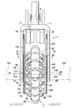
- FIG. 3 is an enlarged cross-sectional view showing a main wheel used in the friction drive device according to the first embodiment.
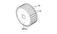
- FIG. 3 is a perspective view showing one embodiment of a drive roller used in the friction drive device according to the first embodiment.
- FIG. 6 is a perspective view showing another embodiment of a drive roller used in the frictional drive device according to the first embodiment.
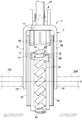
- the enlarged front view which shows the principal part of Embodiment 2 of the friction type drive device by this invention and an omnidirectional mobile body using the same.
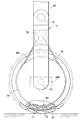
- the enlarged front view which shows the principal part of Embodiment 3 of the friction type drive device by this invention and an omnidirectional mobile body using the same.
- the enlarged side view which shows the principal part of Embodiment 3 of the friction type drive device by this invention and an omnidirectional mobile body using the same.
- the front view which shows the principal part of Embodiment 4 of the friction type drive device by this invention and an omnidirectional mobile body using the same.
- the enlarged front view which shows the principal part of Embodiment 5 of the friction type drive device by this invention and an omnidirectional mobile body using the same.
- the omnidirectional mobile body 1 of the present embodiment has a yoke-like lower vehicle body 7, and the lower vehicle body 7 is capable of rotating a main wheel (traveling wheel) 2 that is a first movable member, although it is indirect. I support it.
- the lower vehicle body 7 has a pair of right and left leg members 7R and 7L that are hinged to each other by a hinge shaft 11.
- a right step 32R is attached to the right leg member 7R
- a left step 32L is attached to the left leg member 7L substantially horizontally.
- the lower end portion of the pole 33 is fixed to the right leg member 7R of the lower vehicle body 7.
- the pole 33 stands vertically above the lower vehicle body 7, and a handlebar 34 extending in the horizontal direction is attached to the upper end of the pole 33.
- a compression coil spring 8 is provided between the right leg member 7R and the left leg member 7L of the lower vehicle body 7. The compression coil spring 8 urges the right leg member 7 ⁇ / b> R and the left leg member 7 ⁇ / b> L, which form the legs of the lower vehicle body 7, to approach each other.
- the lower vehicle body 7, the left and right steps 32R and 32L, the pole 33, and the handle bar 34 are integrally formed with each other, in the present embodiment, the lower vehicle body 7, the left and right steps 32R and 32L, the pole 33, and the handle bar 34 as a whole. Is the base of the omnidirectional mobile body 1.
- An auxiliary wheel 35 is attached to the lower vehicle body 7 by an arm 36.
- the arm 36 is pivotally supported at the upper end by the rear surface (back surface) of the lower vehicle body 7 and can be flipped up.
- the auxiliary wheel 35 is attached to the distal end (lower end) of the arm 36 so as to be rotatable around a horizontal axis, and is located behind the main wheel 2 in the front-rear direction.
- the handle bar 34 is provided with a grip lever 37.
- the grip lever 37 is connected to the arm 36 by a known Bowden cable (not shown), and is lifted up by being grasped by hand.
- the right leg member 7R rotatably supports the right rotating member (second movable member) 4R by the support shaft 6R.
- the left leg member (second movable member) 7L supports the left rotation member 4L rotatably by a support shaft 6L.
- the left and right rotating members 4R, 4L constituting the movable member of the second movable member are arranged around the same central axis (A) with the lower vehicle body 7 around the same central axis (A) with a predetermined axial distance (horizontal distance). Are rotatably attached to each other.
- the pulleys 9R and 9L are integrally formed at the concentric positions on the rotating members 4R and 4L.
- Electric motors 5R and 5L are attached to the right leg member 7R and the left leg member 7L, respectively.
- the electric motor 5R is drivingly connected to the pulley 9R by an endless belt 10R (or a link chain), and rotationally drives the rotating member 4R around the central axis (A) of the support shaft 6R.
- the electric motor 5L is drivingly connected to the pulley 9L by an endless belt 10L (or a link chain), and rotationally drives the rotating member 4L around the central axis (A) of the support shaft 6L.
- the left and right rotating members 4R, 4L are independently driven by the electric motors 5R, 5L.
- the rechargeable battery power supply and control apparatus are mounted in the lower vehicle body 7 and the pole 33 as a power supply of electric motor 5R, 5L.
- Rotating members 4R, 4L have tapered outer peripheral surfaces 12R, 12L on the sides facing each other in a truncated cone shape.
- a plurality of right driving rollers 3R as second free rollers are respectively provided along the circumferential direction which is the moving direction of the rotating member 4R by the support shaft 14R on the bracket 13R. At regular intervals, they are attached so that they can rotate (spin).
- a plurality of left driving rollers 3L which are also second free rollers, are arranged in the circumferential direction, which is the moving direction of the rotating member 4L, by the support shaft 14R on the bracket 13L. It is attached so as to be freely rotatable (spinning) at equal intervals along
- the main wheel 2 is disposed between the left and right rotating members 4R, 4L, and the right driving roller 3R of the left and right rotating members 4R, 4L from the both sides (left and right sides) of the central axis (symmetrical axis) of the main wheel 2 on the left side. It is supported so as to be rotatable about the same central axis (B) (symmetric axis) as the central axis (A) of the left and right rotating members 4R, 4L so as to be sandwiched between the driving rollers 3L.
- the right drive roller 3R and the left drive roller 3L have a high Young's modulus as compared with rubber-like elastic bodies such as aluminum, stainless steel, and hard plastics, including the outer peripheral portions constituting the outer peripheral surfaces 3RA and 3LA. It is made of a material having high hardness and high rigidity.
- the main wheel 2 includes an annular member 22 and a plurality of driven rollers 25 attached to the outer periphery of the annular member 22 so as to be rotatable (spinned) around the tangential axis of the annular member 22 at the arrangement position. It is configured.
- a plurality of driven rollers 25 are arranged along the moving direction of the main wheel 2 (annular member 22), that is, the rotational direction around the central axis, and form a first free roller.
- the annular member 22 is formed of a metal annular shaft.
- a plurality of inner sleeves 23 are attached to the annular member 22 at equal intervals along the circumferential direction of the annular member 22.
- Each of the inner sleeves 23 has a mounting hole 23A bent with the same curvature as that of the annular member 22, and the mounting hole 23A is fitted to the outer periphery of the inner sleeve 23 so as not to move in the circumferential direction and to be non-rotatable.
- the outer peripheral surface 23B of the inner sleeve 23 is a cylindrical surface.
- the annular member 22 may be a combination of polygons or annular units.
- Each of the plurality of driven rollers 25 includes a cylindrical metal sleeve 25A and a cylindrical outer peripheral member 25B which is joined to the outer periphery of the metal sleeve 25A and forms the outer peripheral surface 25C of the driven roller 25.
- the inner sleeve 23 is rotatably mounted on the outer peripheral surface 23B via a needle bearing 26.
- the outer peripheral member 25B of the driven roller 25 is made of a material having a low Young's modulus, a low hardness, and a low rigidity compared to a rubber-like elastic body such as urethane rubber and other elastomer materials such as metals and hard plastics. It is configured.
- the outer peripheral portions constituting the outer peripheral surfaces 3RA and 3LA of the right driving roller 3R and the left driving roller 3L and the outer peripheral portion 25B constituting the outer peripheral surface 25C of the driven roller 25 are different in rigidity.
- the rigidity of the outer peripheral portions constituting the outer peripheral surfaces 3RA and 3LA of the right drive roller 3R and the left drive roller 3L is higher than the rigidity of the outer peripheral portion 25B constituting the outer peripheral surface 25C of the driven roller 25.
- the right driving roller 3R and the left driving roller 3L are urged toward the outer peripheral surface 25C of the driven roller 25 by the spring force of the compression coil spring 8, and contact the outer peripheral surface 25C of the driven roller 25 with the outer peripheral surfaces 3RA and 3LA. Then, power is transmitted to the driven roller 25 by friction. That is, the outer peripheral surfaces 3RA and 3LA of the right driving roller 3R and the left driving roller 3L come into contact with the outer peripheral surface 25C of the driven roller 25 in a torque transmission relationship that transmits the rotation of the rotating members 4R and 4L to the main wheel 2 with frictional force. ing.
- the driven roller 25 is a free roller that comes into contact with an object to which a driving force is applied, and is attached to the annular member 22 in a daisy chain shape, each around the tangential axis of the annular shaft body 46, that is, the cross-sectional center line (C) It can be rotated around an axis equivalent to the circumference, in other words, it can be rotated around the central axis of each driven roller 25 itself.
- the relationship (number) between the driven roller 25, the right driving roller 3R, and the left driving roller 3L is such that at least one pair of the right driving roller 3R and the left driving roller 3L is in contact with the grounded driven roller 25.
- the driven roller 25 that is in a grounded state from the right driving roller 3R and the left driving roller 3L is set so that power is always applied thereto.
- the right driving roller 3R and the left driving roller 3L are rotated in the direction of rotation around the central axis (B) of the main wheel 2 (same as the central axis (A) of the rotating members 4R and 4L) (more precisely, the center at the contact location). It is rotatably arranged around a central axis (D) extending in a direction that is neither orthogonal nor parallel to (circumferential tangential direction around the axis (B)). That is, the right driving roller 3R and the left driving roller 3L are inclined with respect to the rotation direction around the central axis (B) of the main wheel 2 and are relative to the rotation axes (central axis (A)) of the rotating members 4R and 4L.
- the central axes of the right driving roller 3R and the left driving roller 3L have a predetermined inclination angle with respect to the central axis of the driven roller 25 when viewed from the projection plane in the direction of the central axis (A) at the location where each roller is disposed. It is inclined.
- the central axes of the right driving roller 3R and the left driving roller 3L are inclined at an angle with respect to the radial line of the annular shaft body 22 corresponding to the central axis of the driven roller 25, and at the same time, the center lines of the annular shaft body 22 It is inclined at a certain angle with respect to the virtual plane with which it contacts.
- the inclination of this three-dimensional axis line is similar to the inclination of the tooth of a “helical bevel gear” placed on a conical surface at an angle.
- the right driving roller 3R and the left driving roller 3L transmit the rotation of the rotating members 4R and 4L to the driven roller 25 as a lateral force by friction due to contact between the outer peripheral surfaces of the driven roller 25 and each other.
- the rotation of the driven roller 25 around the cross-sectional center line (C) is determined by the rotational speed difference between the rotating members 4R and 4L.
- the main wheel 2 does not rotate (revolve) around the central axis (B) (symmetric axis), and only the driven roller 25 has a sectional center line. (C) It will rotate around.
- the driving force in the extending direction of the central axis (B) of the main wheel 2 that is, the left-right direction is applied to the main wheel 2, and the omnidirectional mobile body 1 moves in the left-right direction.
- the omnidirectional mobile body 1 can move in all directions on the road surface by independently controlling the rotation speed and the rotation direction of the rotating members 4R and 4L by the electric motors 5R and 5L.
- the driven roller 25 of the main wheel 2 is rotated around the cross-sectional center line (C) by the electric motors 5R and 5L while the auxiliary wheel 35 is grounded, the left and right direction (main wheel 2) due to the grounding of the auxiliary wheel 35 is achieved. Since the traveling direction is constrained by the lateral force in the direction of the central axis (B), a moment around the yaw axis (vertical direction) acts on the main wheel 2, and the omnidirectional mobile body 1 can turn. it can.
- the omnidirectional mobile body 1 can change direction with a relatively small turning radius.
- the right driving roller 3R, the left driving roller are used to obtain an accurate movement of the main wheel 2 that controls the movement of the omnidirectional mobile body 1 as desired and to reduce power loss.
- the contact between the outer peripheral surfaces of 3L and the driven roller 25 of the main wheel 2 it is required to reduce the slip between them as much as possible.
- the entire outer peripheral portions constituting the outer peripheral surfaces 3RA and 3LA of the right driving roller 3R and the left driving roller 3L are made of metal or hard plastics, whereas the driven roller 25
- the outer peripheral portion 25B constituting the outer peripheral surface 25C is made of a rubber-like elastic body such as urethane rubber or other elastomer material, and the outer peripheral portions constituting the outer peripheral surfaces 3RA and 3LA of the right driving roller 3R and the left driving roller 3L are rigid.
- the rigidity of the outer peripheral portion 25B constituting the outer peripheral surface 25C of the driven roller 25 is higher than that of the outer peripheral surface of the right driving roller 3R, the left driving roller 3L, and the driven roller 25, the right-side drive on the side having higher rigidity is provided.
- the outer peripheral portion of the driven roller 25 on the side with low rigidity is elastically deformed by the roller 3R and the left driving roller 3L, and the right driving roller 3 , The contact area of the peripheral surfaces of the left driving roller 3L and the driven roller 25 is increased.
- the rigidity of the right driving roller 3R and the left driving roller 3L is higher than the rigidity of the outer peripheral portion constituting the outer peripheral surface 25C of the driven roller 25, that is, the right driving roller 3R and the left driving roller 3L are made of metal or By being made of hard plastics, the right driving roller 3R and the left driving roller 3L, which are positive members for transmitting rotational force, are less elastically deformed than the rubber-like elastic body or the elastomer driven roller 25, and are driven to the right side. Since the elastic deformation of the roller 3R and the left driving roller 3L can be kept substantially zero, fluctuations in propulsive force transmission do not increase.
- the rigidity of the right driving roller 3R and the left driving roller 3L is higher than the rigidity of the outer peripheral portion constituting the outer peripheral surface 25C of the driven roller 25
- the rigidity of the outer peripheral portion constituting the outer peripheral surface 25C of the driven roller 25 is shown. May be higher than the rigidity of the right driving roller 3R and the left driving roller 3L, and the rigidity of the right driving roller 3R and the left driving roller 3L may be different from the rigidity of the outer peripheral portion constituting the outer peripheral surface 25C of the driven roller 25. That's fine.
- a plurality of extending grooves 15 may be repeatedly formed in the circumferential direction, and the outer peripheral surfaces of the right driving roller 3R and the left driving roller 3L may have a repeated uneven shape in the circumferential direction.
- the outer peripheral surface 25C of the driven roller 25 having the lower rigidity bites into the groove 55 on the outer peripheral surface of the right drive roller 3R and the left drive roller 3L due to elastic deformation, and the right drive roller 3R by this bite engagement. Further, the slip between the left driving roller 3L and the driven roller 25 is further reduced.
- the groove cross-sectional shape of the groove 15 is a rectangle in which the corner 16 has an angle close to a right angle. It is preferable. Since the optimum setting for this is affected by the rigidity of the outer peripheral portion constituting the outer peripheral surface 25C of the driven roller 25, the groove cross-sectional shape of the groove 15 is not necessarily rectangular, and the right drive roller 3R, The outer peripheral surface of the driving roller 3L may have a spline shape, a serration shape, or the like. Further, the grooves 15 may be provided on the outer peripheral surfaces of the right driving roller 3R and the left driving roller 3L in a square lattice shape, a diamond lattice shape, or other appropriate patterns.
- outer peripheral surfaces of the right driving roller 3R and the left driving roller 3L may have an uneven shape in which a large number of projections by dimples, hemispheres, cylinders, and prisms are provided by lattice arrangement, staggered arrangement, or irregular arrangement.
- FIG. 5 shows an embodiment in which a large number of cylindrical protrusions 17 are arranged in a grid.
- Embodiment 2 of the friction type driving device according to the present invention and an omnidirectional moving body using the same will be described with reference to FIG. 6, parts corresponding to those in FIG. 2 are denoted by the same reference numerals as those in FIG. 2, and description thereof is omitted.
- the frustoconical rotating members 51 and 52 on the left member 7L and the right member 7 of the lower vehicle body 7 are rotatable concentrically with each other on the central axis (A) by the support shafts 53 and 54, respectively. It is attached.
- An electric motor 55 is attached to the left side member 7L of the lower body 7.
- a pulley (or sprocket) 56 is integrally formed on the rotating member 51 concentrically.
- the electric motor 55 is drivingly connected to the pulley 56 by an endless belt (or link chain) 57 and rotationally drives the rotating member 51 around the central axis (A) of the support shaft 53.
- Another electric motor 58 is attached to the right side member 7R of the lower body 7.
- a pulley (or sprocket) 59 is integrally formed concentrically with the rotating member (second movable member) 52.
- the electric motor 58 is drivingly connected to the pulley 59 by an endless belt (or link chain) 60 and rotationally drives the rotating member 52 around the central axis (A) of the support shaft 54.
- the rotating member 51 has a plurality of arms 62 extending from the tapered outer peripheral surface 61 to the other rotating member 52 side (right side in FIG. 6).
- An annular member 22 of the main wheel 2 is fixedly supported by an equivalent annular member 22 of the wheel 2 and a driven roller 25.
- the main wheel 2 is supported by the lower vehicle body 7 together with the rotating member 51 so as to be rotatable around the central axis (A).
- the lower vehicle body 7 supports the main wheel 2 by the rotating member 51 so as to be rotatable around the central axis (A).
- the rotating member 52 constitutes a second movable member.
- a plurality of driving rollers 63 as second free rollers are respectively provided on the taper outer peripheral surface 61 of the rotating member 52 by brackets 64 and supporting shafts 65.
- the rotating member 52 is attached so as to be freely rotatable (spinning) at equal intervals along the circumferential direction that is the moving direction of the rotating member 52.
- the driving roller 63 is urged in the direction in which the left member 7L and the right member 7 approach each other by the spring force of the compression coil spring 8, so that the driving roller 63 comes into contact with the outer peripheral surface of the driven roller 25 in a torque transmission relationship. It is rotatably attached around a central axis (D) extending in a direction having a twist relationship with respect to the central axis (C) of the driven roller 25. As a result, the rotational axis of the drive roller 63 is twisted with respect to the rotational axis of the driven roller 25 that is in contact therewith.
- the central axis of the driving roller 63 is inclined with a predetermined inclination angle with respect to the central axis of the driven roller 25 as viewed in the projection plane in the direction of the central axis (A) at the location of each roller.
- the central axis of the drive roller 63 is inclined at a certain angle with respect to the radial line of the annular shaft body 22 corresponding to the central axis of the driven roller 25, and at the same time with respect to a virtual plane with which the central line of the annular shaft body 22 is in contact. It is tilted at a certain angle.
- the inclination of this three-dimensional axis line is similar to the inclination of the tooth of a “helical bevel gear” placed on a conical surface at an angle.
- the drive roller 63 revolves and rotates with the rotation of the rotating members 51 and 52 without rotating.
- a lateral force due to the revolution of the roller 63 acts on the driven roller 25 of the main wheel 2 as a component force in the rotation axis direction.
- the main wheel 2 revolves (rotates about the central axis (B)) while being driven to rotate from the rotating member 51 without the driven roller 25 rotating.
- the driving roller 63 revolves while rotating, and the lateral force due to the rotation of the driving row 63 is generated. It acts on the driven roller 25 of the main wheel 2 as a component force in the circumferential direction. As a result, the driven roller 25 rotates (rotates around the cross-sectional center line (C)).
- the omnidirectional mobile body 1 can move in all directions on the road surface by independently controlling the rotational speed and direction of the rotating members 51 and 52 by the electric motors 55 and 58.
- the relationship (number) between the driven roller 25 and the driving roller 63 is such that at least one driving roller 63 is always in contact with the grounded driven roller 25 and is in a grounded state from the driving roller 63.
- the setting is such that power is always applied to the roller 25.
- the driving roller 63 is made of metal or hard plastics, whereas the outer peripheral portion constituting the outer peripheral surface of the driven roller 25 is made of a rubber-like elastic body such as urethane rubber or other elastomer material.
- the rigidity of the driving roller 63 is higher than the rigidity of the outer peripheral portion constituting the outer peripheral surface of the driven roller 25.
- the outer peripheral portion of the driven roller 25 having low rigidity is elastically deformed by the driving roller 63 having high rigidity, and the outer peripheral surfaces of the driving roller 63 and the driven roller 25.
- the contact area between them increases.
- the transmission efficiency of the rotational force due to friction is increased, the slip between the driving roller 63 and the driven roller 25 is reduced, and an accurate movement as the target of the main wheel 2 is obtained, Power loss can be reduced, and the omnidirectional mobile body 1 can be moved in the movement direction of the control target with good economic efficiency.
- Embodiment 3 of the friction type driving device and the omnidirectional mobile body using the same according to the present invention will be described with reference to FIGS. 7 and 8, portions corresponding to those in FIGS. 1 and 2 are denoted by the same reference numerals as those in FIGS. 1 and 2, and description thereof is omitted.
- the outer ring member 71 that forms the first movable member and the inner ring member 72 that forms the second movable member are respectively connected to the left member 7L and the right member 7R of the lower vehicle body 7 by the support shafts 73 and 74, respectively.
- An electric motor 75 is attached to the left side member 7L of the lower body 7.
- a pulley (or sprocket) 76 is integrally formed concentrically with the outer ring member 71.
- the electric motor 75 is drivingly connected to the pulley 76 by an endless belt (or link chain) 77, and rotationally drives the outer ring member 71 around the central axis (A) of the support shaft 73.
- Another electric motor 78 is attached to the right member 7R of the lower body 7.
- a pulley (or sprocket) 79 is integrally formed on the inner ring member 72 concentrically.
- the electric motor 78 is drivingly connected to the pulley 79 by an endless belt (or link chain) 80, and rotationally drives the inner ring member 72 around the central axis (A) of the support shaft 74.
- the outer ring member 71 has a truncated conical shape, and a plurality of barrel-shaped first free rollers 81 are provided on the outer circumferential wall (tapered circumferential surface) of the outer ring member 71 in the circumferential direction of the outer ring member 71 ( (Moving direction) are rotatably attached at equal intervals.
- the first free roller 81 is a free roller that comes into contact with an object to which a driving force is applied, and can rotate around a central axis that extends in a direction that is neither parallel nor orthogonal to the central line of the outer ring member 71. Is attached.
- the central axis of the first free roller 81 has an inclination angle of 45 degrees with respect to the rotation direction of the outer ring member 71 on a tangential plane with respect to the circumferential surface of the outer ring member 71 at each free roller arrangement site. It is inclined.
- the inner ring member 72 has a truncated conical shape like the outer ring member 71, and a plurality of barrel-shaped second free rollers 82 are provided on the inner peripheral member 72 on the outer circumferential wall (tapered circumferential surface) of the inner ring member 72. 72 are attached so as to be rotatable at equal intervals in the circumferential direction.
- the second free roller 82 is in contact with the first free roller 81 and rotates around a central axis extending in a direction in which the first free roller 81 of the contact partner is twisted with respect to the central axis It is attached as possible.
- the center axis of the second free roller 82 is the center of the first free roller 81 when viewed from the tangential plane (projection plane) with respect to the circumferential surface of the outer ring member 71 and the inner ring member 72 at each free roller arrangement site. It is inclined at an inclination angle of 90 degrees with respect to the axis.
- the left member 7L and the right member 7 are urged toward each other by the spring force of the compression coil spring 8, so that the first free roller 81 and the second free roller 82 that make a pair.
- the contact with becomes dense.
- the second free roller 82 comes into contact with the first free roller 81 in a torque transmission relationship.
- the omnidirectional mobile body 1 can move in all directions on the road surface by independently controlling the rotation speed and the rotation direction of the outer ring member 71 and the inner ring member 72 by the electric motors 75 and 76.
- the second free roller 82 is made of metal or hard plastics, whereas the outer peripheral portion constituting the outer peripheral surface of the first free roller 81 is a rubber-like elastic body such as urethane rubber, or the like.
- the rigidity of the second free roller 82 is higher than the rigidity of the outer peripheral portion constituting the outer peripheral surface of the first free roller 81.
- the outer peripheral portion of the first free roller 81 having low rigidity is elastically deformed by the second free roller 82 having high rigidity.
- the contact area between the outer peripheral surfaces of the first free roller 81 and the second free roller 82 increases.
- the transmission efficiency of the rotational force due to the friction is increased, the slip between the first free roller 81 and the second free roller 82 is reduced, and the main wheel 2 can be accurately as intended.
- the power loss can be reduced, and the omnidirectional mobile body 1 can be moved in the movement direction of the control target with good economic efficiency.
- Embodiment 4 of the friction type drive device and the omnidirectional mobile body using the same according to the present invention will be described with reference to FIG. 9, parts corresponding to those in FIGS. 7 and 8 are denoted by the same reference numerals as those in FIGS. 7 and 8, and description thereof is omitted.
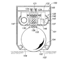
- the omnidirectional mobile body 100 includes a box-shaped vehicle body 101 having a lower opening, a traveling sphere 102 provided in the vehicle body 101 so as to be able to roll in all directions, and a friction drive device 110.
- the lower region of the traveling sphere 102 is exposed below the lower opening 103 of the vehicle body 101 and comes into contact with the floor and road surface so as to allow rolling.
- the traveling sphere 102 is prevented from dropping below the vehicle body 101 due to the engagement with a support ball 104 that is provided on the periphery of the lower opening 103 of the vehicle body 101 so as to be able to roll.
- the friction type driving device 110 includes the outer ring member 71, the inner ring member 72, the first free roller 81, the second free roller 82, and the like according to the third embodiment.
- the first free roller 81 is in contact with the spherical surface of the traveling sphere 18 in a torque transmission relationship.
- the traveling sphere 102 is driven to roll in all directions by the friction drive device 110, and the vehicle body 101 moves in all directions.
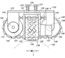
- the omnidirectional mobile body 100 of the present embodiment includes a box-shaped vehicle body 101 having a downward opening, a traveling sphere 102 provided in the vehicle body 101 so as to be able to roll in all directions, and a friction drive device 120.
- a friction type driving device 120 is arranged in a form located above the traveling sphere 102.
- the friction drive device 120 includes a first base body 121 and a second base body 122, and the second base body 122 is fixed to the upper member 105 of the vehicle body 101 and is suspended and fixed from the upper member 105.
- the first crawler driving body 130 is attached to the first base 121, and the second crawler driving body 140 is attached to the second base 1222.
- the first crawler driving body 130 includes a driving wheel 131, a driven wheel 132, and a driven wheel 132, which are rotatably disposed on the first base 121 121 in a direction orthogonal to the plane of FIG.
- a first crawler belt 133 which is a first endless track (first movable member) spanned between the drive wheel 131 and the driven wheel 132.
- the first crawler belt 133 is formed by hinge-connecting a large number of slat pieces 138 in an endless belt shape.
- the drive wheel 131 and the driven wheel 132 are rotatably supported by support shafts 135 and 136 on brackets 133 and 134 attached to the first base 121, respectively.
- An electric motor 137 for rotating the drive wheel 131 is attached to the bracket 133.
- the second crawler driving body 140 includes a driving wheel 141 and a driven wheel 142 that are disposed on the second base 121 so as to be separated from each other in the left-right direction (Y-axis direction) as viewed in FIGS. And a second crawler belt 143 that is a second endless track (second movable member) spanned between the wheel 141 and the driven wheel 142.
- the second crawler belt 143 is formed by hinge-connecting a large number of slat pieces 148 in an endless belt shape.
- the drive wheel 141 and the driven wheel 142 are rotatably supported by support shafts 145 and 146 on brackets 143 and 144 attached to the second base 122, respectively.
- An electric motor 147 that rotationally drives the drive wheel 141 is attached to the bracket 143.
- the first crawler belt 133 and the second crawler belt 143 extend in directions orthogonal to each other in plan view, and the paths between the wheels intersect each other vertically.
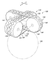
- the first free roller 139 is a free roller that comes into contact with an object to which a driving force is applied with an outer peripheral surface, that is, the spherical surface of the traveling sphere 102, and is in the traveling direction (X direction) of the first crawler belt 10. It is rotatable around a central axis extending in a non-orthogonal direction.
- the non-orthogonal direction here refers to a direction other than the direction in which the central axis of the first free roller 139 is orthogonal to the traveling direction of the first crawler belt 10, that is, the traveling direction of the first crawler belt 10. Or is in the same direction as the traveling direction.
- the central axis of the first free roller 139 is inclined at an inclination angle of 45 degrees with respect to the traveling direction of the first crawler belt 10 in the XY virtual plane.
- a cylindrical second free roller 149 is rotatably attached to each slat piece 148 of the second crawler belt 143.
- the second free roller 149 is in contact with the rolling surface (outer peripheral surface) of the first free roller 139 at the intersection in the inter-wheel path with the first crawler belt 133 in the torque transmission relationship, and the first contact partner first
- the free roller 139 is attached so as to be rotatable around a central axis extending in a direction in which the torsional positional relationship is established with respect to the central axis.
- the positional relationship of torsion refers to a positional relationship in which two straight lines (axis lines) in the space are not parallel and do not cross each other, that is, cannot be on the same plane.
- the central axis of the second free roller 149 is inclined at an inclination angle of 45 degrees with respect to the central axis of the first free roller 139 when viewed in the XY projection plane. Furthermore, in other words, the central axis of the second free roller 149 is not parallel (twisted) with the central axis of the first free roller 139 and is orthogonal to the moving direction (Y direction) of the first crawler belt 133. If not, it ’s good.
- the base 121 and the base 122 are orthogonally arranged according to the wheel arrangement direction of the first crawler belt 133 and the second free roller 143, and are connected by a connecting rod 123 so as to be relatively displaceable in the vertical direction. .
- a compression coil spring 124 is incorporated in the connecting rod 123.
- the compression coil spring 124 urges the base 121 downward with respect to the base 122.
- the outer peripheral surface of the second free roller 149 and the outer peripheral surface of the first free roller 139 are always predetermined at the intersection of the first crawler belt 133 and the second crawler belt 143.
- the contact is made with a pressing force greater than the value, that is, a pressing force necessary to transmit motion (torque transmission) by frictional force.
- the omnidirectional mobile body 100 configured in this way, for example, when the travel of the first crawler belt 133 is stopped and only the second crawler belt 143 is driven by the electric motor 147, the second crawler belt 143 is driven. At the same time, a second free roller 149 provided on the second free roller 149 moves in the same direction.
- the first crawler belt 143 travels to the first free roller 139 that is in contact with the outer peripheral surfaces in a state of intersecting with the second free roller 149 with an inclination of 45 degrees (twisted relationship).
- a rotational force is applied by a component of the thrust force acting in the axial direction of the second free roller 149.
- the first free roller 139 rotates, and the traveling sphere 102 rolls in the rotation direction of the first free roller 139.
- the first free roller 139 moves as the first crawler belt 133 travels, and the first free roller 139 rotates and rotates.
- the traveling sphere 102 rolls in the direction in which the movement is configured.
- the traveling sphere 102 can be rolled in all directions by controlling the traveling direction of the first crawler belt 133 and the second crawler belt 143 and the respective peripheral speeds (ratio).
- the direction moving body 100 can travel in all directions.
- the second free roller 149 is made of metal or hard plastic, whereas the outer peripheral portion constituting the outer peripheral surface of the first free roller 139 is a rubber-like elastic body such as urethane rubber, or the like.
- the rigidity of the second free roller 149 is higher than the rigidity of the outer peripheral portion constituting the outer peripheral surface of the first free roller 139.
- the outer peripheral portion of the first free roller 139 having a low rigidity is elastically deformed by the second free roller 149 having a high rigidity.
- the contact area between the outer peripheral surfaces of the first free roller 139 and the second free roller 149 increases.
- the transmission efficiency of the rotational force due to friction is increased, the slip between the first free roller 139 and the second free roller 149 is reduced, and an accurate movement as desired can be obtained.
- the power loss can be reduced, and the omnidirectional mobile body 1 can be moved in the moving direction of the control target with good economic efficiency.
- the difference in rigidity between the two rollers in contact with each other is not only the difference in Young's modulus or hardness of the material constituting the outer peripheral portion of the roller, but also the cross-sectional shape of the outer peripheral portion of the roller, the support structure, etc. It can also be given by the difference in structure.
Landscapes
- Engineering & Computer Science (AREA)
- Mechanical Engineering (AREA)
- Chemical & Material Sciences (AREA)
- Combustion & Propulsion (AREA)
- Transportation (AREA)
- Friction Gearing (AREA)
- Motorcycle And Bicycle Frame (AREA)
Abstract
Description
擦式駆動装置。
全方向移動体。
2 主輪
3R 右側駆動ローラ
3L 左側駆動ローラ
4R、4L 回転部材
7 下部車体
15 溝
17 円柱突起
22 円環部材
25 従動ローラ
51、52 回転部材
63 駆動ローラ
71 外輪部材
72 内輪部材
81 第1のフリーローラ
82 第2のフリーローラ
102 走行用球体
130 第1のクローラ駆動体
133 第1のクローラベルト
139 第1のフリーローラ
140 第2のクローラ駆動体
143 第2のクローラベルト
149 第2のフリーローラ
Claims (9)
- 基体と、
前記基体に、それぞれ移動可能に支持された第1の可動部材及び第2の可動部材と、
前記第1の可動部材に当該第1の可動部材の移動方向に沿って複数個配置され、各々自身の中心軸線周りに回転自在の第1のフリーローラと、
前記第2の可動部材に当該第2の可動部材の移動方向に沿って複数個配置され、各々自身の中心軸線周りに回転自在の第2のフリーローラとを有し、
前記第1の可動部材と前記第2の可動部材の少なくとも一方の移動に伴って前記第1のフリーローラが前記第2のフリーローラの対応するものにおいて、それぞれの回転軸線が互いに平行をなすことなく外周面同士で接触し、前記第2のフリーローラより前記第1のフリーローラへ摩擦によって動力を伝達し、前記第1のフリーローラが駆動対象に接触する摩擦式駆動装置であって、
前記第1のフリーローラの前記外周面を構成する外周部分と、前記第2のフリーローラの前記外周面を構成する外周部分との剛性が互いに異なっている摩擦式駆動装置。 - 前記第1のフリーローラと前記第2のフリーローラのうち、外周部分の剛性が高い側のフリーローラの外周面に凹凸が形成されている請求項1に記載の摩擦式駆動装置。
- 前記第1のフリーローラと前記第2のフリーローラのうち、外周部分の剛性が低い側のフリーローラの外周部分がゴム状弾性体により構成されている請求項1に記載の摩擦式駆動装置。
- 前記第1のフリーローラの回転軸線が、それに対して接触する前記第2のフリーローラの回転軸線に対してねじれの位置関係にある請求項1に記載の摩擦式駆動装置。
- 前記第1の可動部材は、自身の中心軸線周りに周り回転可能な円環部材を含む主輪により構成され、前記第2の可動部材は、自身の中心軸線周りに回転駆動される回転部材により構成され、前記第1のフリーローラは、各々前記円環部材の外周に自転可能に取り付けられ、前記第2のフリーローラは、前記回転部材の中心軸線周りに配置されている請求項1に記載の摩擦式駆動装置。
- 前記第1の可動部材と前記第2の可動部材は、各々一対のローラに巻き掛けられて互いにある角度をなす第1の無限軌道帯と第2の無限軌道帯を含み、前記第1の無限軌道帯に前記第1のフリーローラが、前記第2の無限軌道帯に前記第2のフリーローラが各々配置されている請求項1に記載の摩擦式駆動装置。
- 前記第1の可動部材と前記第2の可動部材は、互いに同軸の回転軸線を有する第1の円環体と第2の円環体を含み、前記第1のフリーローラは、前記第1の円環体の中心軸線周りに配置され、前記第2のフリーローラは、前記第2の円環体の中心軸線周りに配置されている請求項1に記載の摩擦式駆動装置。
- 請求項1から7の何れか一項に記載の摩擦式駆動装置を含み、前記第1のフリーローラが路面或いは床面に接触して走行する全方向移動体。
- 請求項1から7の何れか一項に記載の摩擦式駆動装置を含み、前記第1のフリーローラ
の駆動対象として転動自在の球体を含み、前記球体が路面或いは床面に接触して走行する全方向移動体。
Priority Applications (5)
| Application Number | Priority Date | Filing Date | Title |
|---|---|---|---|
| JP2010536683A JP5396398B2 (ja) | 2008-11-04 | 2009-11-02 | 摩擦式駆動装置及びそれを用いた全方向移動体 |
| CN2009801502623A CN102245397B (zh) | 2008-11-04 | 2009-11-02 | 摩擦式驱动装置及使用该摩擦式驱动装置的全方向移动体 |
| KR1020117012063A KR101245797B1 (ko) | 2008-11-04 | 2009-11-02 | 마찰식 구동 장치 및 그것을 이용한 전방향 이동체 |
| US13/127,347 US8499863B2 (en) | 2008-11-04 | 2009-11-02 | Friction drive device and OMNI-directional vehicle using the same |
| DE112009002676.1T DE112009002676B4 (de) | 2008-11-04 | 2009-11-02 | Reibungsantriebsvorrichtung und Allrichtungsfahrzeug, das diese verwendet |
Applications Claiming Priority (2)
| Application Number | Priority Date | Filing Date | Title |
|---|---|---|---|
| JP2008283474 | 2008-11-04 | ||
| JP2008-283474 | 2008-11-04 |
Publications (1)
| Publication Number | Publication Date |
|---|---|
| WO2010052890A1 true WO2010052890A1 (ja) | 2010-05-14 |
Family
ID=42152704
Family Applications (1)
| Application Number | Title | Priority Date | Filing Date |
|---|---|---|---|
| PCT/JP2009/005832 Ceased WO2010052890A1 (ja) | 2008-11-04 | 2009-11-02 | 摩擦式駆動装置及びそれを用いた全方向移動体 |
Country Status (6)
| Country | Link |
|---|---|
| US (1) | US8499863B2 (ja) |
| JP (1) | JP5396398B2 (ja) |
| KR (1) | KR101245797B1 (ja) |
| CN (1) | CN102245397B (ja) |
| DE (1) | DE112009002676B4 (ja) |
| WO (1) | WO2010052890A1 (ja) |
Cited By (4)
| Publication number | Priority date | Publication date | Assignee | Title |
|---|---|---|---|---|
| JP2017056763A (ja) * | 2015-09-14 | 2017-03-23 | 本田技研工業株式会社 | 摩擦式走行装置および乗物 |
| JP2021191645A (ja) * | 2020-06-05 | 2021-12-16 | 本田技研工業株式会社 | ドライブディスク |
| JP2021191646A (ja) * | 2020-06-05 | 2021-12-16 | 本田技研工業株式会社 | ドライブディスク |
| US11273669B2 (en) | 2019-06-12 | 2022-03-15 | Toyota Motor North America, Inc. | Omni-track systems for wheels |
Families Citing this family (12)
| Publication number | Priority date | Publication date | Assignee | Title |
|---|---|---|---|---|
| JP5398446B2 (ja) * | 2009-09-18 | 2014-01-29 | 本田技研工業株式会社 | 駆動装置 |
| US9174338B2 (en) * | 2011-06-29 | 2015-11-03 | Alexander G. Ouellet | Robotic movement system |
| JP2013129414A (ja) * | 2011-11-26 | 2013-07-04 | Honda Motor Co Ltd | 全方向移動車両 |
| JP5813573B2 (ja) | 2012-05-14 | 2015-11-17 | 本田技研工業株式会社 | 倒立振子型車両 |
| TWM473321U (zh) * | 2013-08-06 | 2014-03-01 | Generalplus Technology Inc | 自平衡行動載具 |
| CN103895770A (zh) * | 2014-04-15 | 2014-07-02 | 上海万硅电子有限公司 | 一种前后左右自平衡电动独轮车 |
| DE102015007634A1 (de) | 2015-06-15 | 2016-12-15 | Rainer Röck | Omnidirektional-Rad-System |
| CN105480014B (zh) * | 2016-02-16 | 2018-09-04 | 河海大学常州校区 | 减振且可越障全向移动轮系装置及工作方法、移动平台 |
| JP6951611B2 (ja) * | 2016-07-01 | 2021-10-20 | 公立大学法人公立諏訪東京理科大学 | 全方向移動装置及びその姿勢制御方法 |
| CN109955998B (zh) * | 2017-12-25 | 2021-02-23 | 深圳乐行天下科技有限公司 | 空心轮装置及代步工具 |
| JP6698116B2 (ja) * | 2018-03-22 | 2020-05-27 | 本田技研工業株式会社 | 移動体 |
| CA3043879A1 (en) * | 2019-05-21 | 2020-11-21 | Stephen Sutherland | Shock-tolerant omni wheel |
Citations (4)
| Publication number | Priority date | Publication date | Assignee | Title |
|---|---|---|---|---|
| JPH10129517A (ja) * | 1996-11-06 | 1998-05-19 | Toyota Motor Corp | 駆動装置 |
| JP2001354156A (ja) * | 2000-06-14 | 2001-12-25 | Kawasaki Heavy Ind Ltd | 球状駆動輪を用いる全方向移動装置 |
| JP2005067334A (ja) * | 2003-08-22 | 2005-03-17 | Hideki Nemoto | 全方向移動用車輪およびこれに使用されるフレキシブルタイヤ |
| JP2005344777A (ja) * | 2004-06-01 | 2005-12-15 | Furukawa Electric Co Ltd:The | 球体輪駆動機構及びその走行方法 |
Family Cites Families (20)
| Publication number | Priority date | Publication date | Assignee | Title |
|---|---|---|---|---|
| US4076263A (en) * | 1975-04-04 | 1978-02-28 | Rand Robert K | Ball skate |
| WO2006068007A1 (ja) * | 2004-12-20 | 2006-06-29 | Shinichiro Fuji | 全方向移動車輪および移動装置、搬送装置およびマッサージ装置 |
| JP5358432B2 (ja) | 2007-04-20 | 2013-12-04 | 本田技研工業株式会社 | 全方向駆動装置及びそれを用いた全方向移動車 |
| JP5292283B2 (ja) | 2007-04-20 | 2013-09-18 | 本田技研工業株式会社 | 全方向駆動装置及びそれを用いた全方向移動車 |
| JP5292286B2 (ja) * | 2007-05-16 | 2013-09-18 | 本田技研工業株式会社 | 全方向に移動可能な乗り物 |
| CN201092360Y (zh) * | 2007-07-25 | 2008-07-30 | 李海栓 | 独轮车 |
| US8827375B2 (en) * | 2008-12-05 | 2014-09-09 | Honda Motor Co., Ltd. | Wheel, and friction drive device and omni-directional vehicle using the same |
| JP5484019B2 (ja) * | 2008-12-10 | 2014-05-07 | 本田技研工業株式会社 | 摩擦駆動式車両 |
| JP2010260501A (ja) * | 2009-05-11 | 2010-11-18 | Honda Motor Co Ltd | 摩擦式駆動装置及び全方向移動車 |
| JP5386282B2 (ja) * | 2009-09-18 | 2014-01-15 | 本田技研工業株式会社 | 歩行補助装置 |
| US8353378B2 (en) * | 2009-09-18 | 2013-01-15 | Honda Motor Co., Ltd. | Frictional drive device and inverted pendulum type vehicle using the same |
| JP5401233B2 (ja) * | 2009-09-18 | 2014-01-29 | 本田技研工業株式会社 | 倒立振子型移動体 |
| JP5398446B2 (ja) * | 2009-09-18 | 2014-01-29 | 本田技研工業株式会社 | 駆動装置 |
| JP5398445B2 (ja) * | 2009-09-18 | 2014-01-29 | 本田技研工業株式会社 | 全方向移動車両 |
| JP5292242B2 (ja) * | 2009-09-21 | 2013-09-18 | 本田技研工業株式会社 | 摩擦式駆動装置および倒立振子型移動体 |
| JP5352394B2 (ja) * | 2009-09-22 | 2013-11-27 | 本田技研工業株式会社 | 摩擦式駆動装置および摩擦式駆動装置を有する倒立振子型移動体 |
| JP2011068222A (ja) * | 2009-09-24 | 2011-04-07 | Honda Motor Co Ltd | 倒立振子型車両の制御装置 |
| JP5358374B2 (ja) * | 2009-09-24 | 2013-12-04 | 本田技研工業株式会社 | 車両 |
| US8424621B2 (en) * | 2010-07-23 | 2013-04-23 | Toyota Motor Engineering & Manufacturing North America, Inc. | Omni traction wheel system and methods of operating the same |
| US8408339B2 (en) * | 2010-10-12 | 2013-04-02 | Honda Motor Co., Ltd. | Frictional drive device and inverted pendulum type vehicle using the same |
-
2009
- 2009-11-02 DE DE112009002676.1T patent/DE112009002676B4/de active Active
- 2009-11-02 KR KR1020117012063A patent/KR101245797B1/ko not_active Expired - Fee Related
- 2009-11-02 US US13/127,347 patent/US8499863B2/en active Active
- 2009-11-02 CN CN2009801502623A patent/CN102245397B/zh not_active Expired - Fee Related
- 2009-11-02 JP JP2010536683A patent/JP5396398B2/ja active Active
- 2009-11-02 WO PCT/JP2009/005832 patent/WO2010052890A1/ja not_active Ceased
Patent Citations (4)
| Publication number | Priority date | Publication date | Assignee | Title |
|---|---|---|---|---|
| JPH10129517A (ja) * | 1996-11-06 | 1998-05-19 | Toyota Motor Corp | 駆動装置 |
| JP2001354156A (ja) * | 2000-06-14 | 2001-12-25 | Kawasaki Heavy Ind Ltd | 球状駆動輪を用いる全方向移動装置 |
| JP2005067334A (ja) * | 2003-08-22 | 2005-03-17 | Hideki Nemoto | 全方向移動用車輪およびこれに使用されるフレキシブルタイヤ |
| JP2005344777A (ja) * | 2004-06-01 | 2005-12-15 | Furukawa Electric Co Ltd:The | 球体輪駆動機構及びその走行方法 |
Cited By (6)
| Publication number | Priority date | Publication date | Assignee | Title |
|---|---|---|---|---|
| JP2017056763A (ja) * | 2015-09-14 | 2017-03-23 | 本田技研工業株式会社 | 摩擦式走行装置および乗物 |
| US11273669B2 (en) | 2019-06-12 | 2022-03-15 | Toyota Motor North America, Inc. | Omni-track systems for wheels |
| JP2021191645A (ja) * | 2020-06-05 | 2021-12-16 | 本田技研工業株式会社 | ドライブディスク |
| JP2021191646A (ja) * | 2020-06-05 | 2021-12-16 | 本田技研工業株式会社 | ドライブディスク |
| JP7349960B2 (ja) | 2020-06-05 | 2023-09-25 | 本田技研工業株式会社 | ドライブディスク |
| JP7349959B2 (ja) | 2020-06-05 | 2023-09-25 | 本田技研工業株式会社 | ドライブディスク |
Also Published As
| Publication number | Publication date |
|---|---|
| KR20110089310A (ko) | 2011-08-05 |
| JP5396398B2 (ja) | 2014-01-22 |
| DE112009002676T5 (de) | 2013-05-16 |
| US8499863B2 (en) | 2013-08-06 |
| CN102245397B (zh) | 2013-12-11 |
| US20110260523A1 (en) | 2011-10-27 |
| KR101245797B1 (ko) | 2013-03-20 |
| CN102245397A (zh) | 2011-11-16 |
| DE112009002676B4 (de) | 2014-08-07 |
| JPWO2010052890A1 (ja) | 2012-04-05 |
Similar Documents
| Publication | Publication Date | Title |
|---|---|---|
| JP5396398B2 (ja) | 摩擦式駆動装置及びそれを用いた全方向移動体 | |
| JP5443387B2 (ja) | 車輪及びそれを用いた摩擦式駆動装置及び全方向移動体 | |
| JP5358432B2 (ja) | 全方向駆動装置及びそれを用いた全方向移動車 | |
| JP5292283B2 (ja) | 全方向駆動装置及びそれを用いた全方向移動車 | |
| JP5292286B2 (ja) | 全方向に移動可能な乗り物 | |
| JP5687174B2 (ja) | 全方向移動装置用の走行車輪、摩擦式駆動装置および全方向移動装置 | |
| JP6424131B2 (ja) | 摩擦式走行装置 | |
| JP5506231B2 (ja) | 車輪及びそれを用いた摩擦式駆動装置及び全方向移動車 | |
| JP5426682B2 (ja) | 摩擦式駆動装置および倒立振子型移動体 | |
| US9573416B1 (en) | Wheel assembly with multi-sphere omniwheels and omnidirectional devices including the wheel assembly | |
| US20180147442A1 (en) | Omnidirectional treadmill apparatus | |
| US20170210444A1 (en) | Frictional propulsion device and vehicle using same | |
| JP6417305B2 (ja) | 摩擦式走行装置および乗物 | |
| JP2016203683A (ja) | 摩擦式走行装置および全方向移動装置 | |
| JP4427956B2 (ja) | 移動装置 | |
| JP2018047879A (ja) | 車輪装置 |
Legal Events
| Date | Code | Title | Description |
|---|---|---|---|
| WWE | Wipo information: entry into national phase |
Ref document number: 200980150262.3 Country of ref document: CN |
|
| 121 | Ep: the epo has been informed by wipo that ep was designated in this application |
Ref document number: 09824591 Country of ref document: EP Kind code of ref document: A1 |
|
| WWE | Wipo information: entry into national phase |
Ref document number: 2010536683 Country of ref document: JP |
|
| WWE | Wipo information: entry into national phase |
Ref document number: 1120090026761 Country of ref document: DE |
|
| ENP | Entry into the national phase |
Ref document number: 20117012063 Country of ref document: KR Kind code of ref document: A |
|
| WWE | Wipo information: entry into national phase |
Ref document number: 13127347 Country of ref document: US |
|
| 122 | Ep: pct application non-entry in european phase |
Ref document number: 09824591 Country of ref document: EP Kind code of ref document: A1 |