WO2010050345A1 - 車両用駆動装置 - Google Patents
車両用駆動装置 Download PDFInfo
- Publication number
- WO2010050345A1 WO2010050345A1 PCT/JP2009/067477 JP2009067477W WO2010050345A1 WO 2010050345 A1 WO2010050345 A1 WO 2010050345A1 JP 2009067477 W JP2009067477 W JP 2009067477W WO 2010050345 A1 WO2010050345 A1 WO 2010050345A1
- Authority
- WO
- WIPO (PCT)
- Prior art keywords
- bearing
- oil
- drive device
- oil passage
- partition
- Prior art date
Links
Images


Classifications
-
- B—PERFORMING OPERATIONS; TRANSPORTING
- B60—VEHICLES IN GENERAL
- B60K—ARRANGEMENT OR MOUNTING OF PROPULSION UNITS OR OF TRANSMISSIONS IN VEHICLES; ARRANGEMENT OR MOUNTING OF PLURAL DIVERSE PRIME-MOVERS IN VEHICLES; AUXILIARY DRIVES FOR VEHICLES; INSTRUMENTATION OR DASHBOARDS FOR VEHICLES; ARRANGEMENTS IN CONNECTION WITH COOLING, AIR INTAKE, GAS EXHAUST OR FUEL SUPPLY OF PROPULSION UNITS IN VEHICLES
- B60K6/00—Arrangement or mounting of plural diverse prime-movers for mutual or common propulsion, e.g. hybrid propulsion systems comprising electric motors and internal combustion engines ; Control systems therefor, i.e. systems controlling two or more prime movers, or controlling one of these prime movers and any of the transmission, drive or drive units Informative references: mechanical gearings with secondary electric drive F16H3/72; arrangements for handling mechanical energy structurally associated with the dynamo-electric machine H02K7/00; machines comprising structurally interrelated motor and generator parts H02K51/00; dynamo-electric machines not otherwise provided for in H02K see H02K99/00
- B60K6/20—Arrangement or mounting of plural diverse prime-movers for mutual or common propulsion, e.g. hybrid propulsion systems comprising electric motors and internal combustion engines ; Control systems therefor, i.e. systems controlling two or more prime movers, or controlling one of these prime movers and any of the transmission, drive or drive units Informative references: mechanical gearings with secondary electric drive F16H3/72; arrangements for handling mechanical energy structurally associated with the dynamo-electric machine H02K7/00; machines comprising structurally interrelated motor and generator parts H02K51/00; dynamo-electric machines not otherwise provided for in H02K see H02K99/00 the prime-movers consisting of electric motors and internal combustion engines, e.g. HEVs
- B60K6/22—Arrangement or mounting of plural diverse prime-movers for mutual or common propulsion, e.g. hybrid propulsion systems comprising electric motors and internal combustion engines ; Control systems therefor, i.e. systems controlling two or more prime movers, or controlling one of these prime movers and any of the transmission, drive or drive units Informative references: mechanical gearings with secondary electric drive F16H3/72; arrangements for handling mechanical energy structurally associated with the dynamo-electric machine H02K7/00; machines comprising structurally interrelated motor and generator parts H02K51/00; dynamo-electric machines not otherwise provided for in H02K see H02K99/00 the prime-movers consisting of electric motors and internal combustion engines, e.g. HEVs characterised by apparatus, components or means specially adapted for HEVs
- B60K6/26—Arrangement or mounting of plural diverse prime-movers for mutual or common propulsion, e.g. hybrid propulsion systems comprising electric motors and internal combustion engines ; Control systems therefor, i.e. systems controlling two or more prime movers, or controlling one of these prime movers and any of the transmission, drive or drive units Informative references: mechanical gearings with secondary electric drive F16H3/72; arrangements for handling mechanical energy structurally associated with the dynamo-electric machine H02K7/00; machines comprising structurally interrelated motor and generator parts H02K51/00; dynamo-electric machines not otherwise provided for in H02K see H02K99/00 the prime-movers consisting of electric motors and internal combustion engines, e.g. HEVs characterised by apparatus, components or means specially adapted for HEVs characterised by the motors or the generators
-
- B—PERFORMING OPERATIONS; TRANSPORTING
- B60—VEHICLES IN GENERAL
- B60K—ARRANGEMENT OR MOUNTING OF PROPULSION UNITS OR OF TRANSMISSIONS IN VEHICLES; ARRANGEMENT OR MOUNTING OF PLURAL DIVERSE PRIME-MOVERS IN VEHICLES; AUXILIARY DRIVES FOR VEHICLES; INSTRUMENTATION OR DASHBOARDS FOR VEHICLES; ARRANGEMENTS IN CONNECTION WITH COOLING, AIR INTAKE, GAS EXHAUST OR FUEL SUPPLY OF PROPULSION UNITS IN VEHICLES
- B60K6/00—Arrangement or mounting of plural diverse prime-movers for mutual or common propulsion, e.g. hybrid propulsion systems comprising electric motors and internal combustion engines ; Control systems therefor, i.e. systems controlling two or more prime movers, or controlling one of these prime movers and any of the transmission, drive or drive units Informative references: mechanical gearings with secondary electric drive F16H3/72; arrangements for handling mechanical energy structurally associated with the dynamo-electric machine H02K7/00; machines comprising structurally interrelated motor and generator parts H02K51/00; dynamo-electric machines not otherwise provided for in H02K see H02K99/00
- B60K6/20—Arrangement or mounting of plural diverse prime-movers for mutual or common propulsion, e.g. hybrid propulsion systems comprising electric motors and internal combustion engines ; Control systems therefor, i.e. systems controlling two or more prime movers, or controlling one of these prime movers and any of the transmission, drive or drive units Informative references: mechanical gearings with secondary electric drive F16H3/72; arrangements for handling mechanical energy structurally associated with the dynamo-electric machine H02K7/00; machines comprising structurally interrelated motor and generator parts H02K51/00; dynamo-electric machines not otherwise provided for in H02K see H02K99/00 the prime-movers consisting of electric motors and internal combustion engines, e.g. HEVs
- B60K6/22—Arrangement or mounting of plural diverse prime-movers for mutual or common propulsion, e.g. hybrid propulsion systems comprising electric motors and internal combustion engines ; Control systems therefor, i.e. systems controlling two or more prime movers, or controlling one of these prime movers and any of the transmission, drive or drive units Informative references: mechanical gearings with secondary electric drive F16H3/72; arrangements for handling mechanical energy structurally associated with the dynamo-electric machine H02K7/00; machines comprising structurally interrelated motor and generator parts H02K51/00; dynamo-electric machines not otherwise provided for in H02K see H02K99/00 the prime-movers consisting of electric motors and internal combustion engines, e.g. HEVs characterised by apparatus, components or means specially adapted for HEVs
- B60K6/40—Arrangement or mounting of plural diverse prime-movers for mutual or common propulsion, e.g. hybrid propulsion systems comprising electric motors and internal combustion engines ; Control systems therefor, i.e. systems controlling two or more prime movers, or controlling one of these prime movers and any of the transmission, drive or drive units Informative references: mechanical gearings with secondary electric drive F16H3/72; arrangements for handling mechanical energy structurally associated with the dynamo-electric machine H02K7/00; machines comprising structurally interrelated motor and generator parts H02K51/00; dynamo-electric machines not otherwise provided for in H02K see H02K99/00 the prime-movers consisting of electric motors and internal combustion engines, e.g. HEVs characterised by apparatus, components or means specially adapted for HEVs characterised by the assembly or relative disposition of components
- B60K6/405—Housings
-
- B—PERFORMING OPERATIONS; TRANSPORTING
- B60—VEHICLES IN GENERAL
- B60K—ARRANGEMENT OR MOUNTING OF PROPULSION UNITS OR OF TRANSMISSIONS IN VEHICLES; ARRANGEMENT OR MOUNTING OF PLURAL DIVERSE PRIME-MOVERS IN VEHICLES; AUXILIARY DRIVES FOR VEHICLES; INSTRUMENTATION OR DASHBOARDS FOR VEHICLES; ARRANGEMENTS IN CONNECTION WITH COOLING, AIR INTAKE, GAS EXHAUST OR FUEL SUPPLY OF PROPULSION UNITS IN VEHICLES
- B60K6/00—Arrangement or mounting of plural diverse prime-movers for mutual or common propulsion, e.g. hybrid propulsion systems comprising electric motors and internal combustion engines ; Control systems therefor, i.e. systems controlling two or more prime movers, or controlling one of these prime movers and any of the transmission, drive or drive units Informative references: mechanical gearings with secondary electric drive F16H3/72; arrangements for handling mechanical energy structurally associated with the dynamo-electric machine H02K7/00; machines comprising structurally interrelated motor and generator parts H02K51/00; dynamo-electric machines not otherwise provided for in H02K see H02K99/00
- B60K6/20—Arrangement or mounting of plural diverse prime-movers for mutual or common propulsion, e.g. hybrid propulsion systems comprising electric motors and internal combustion engines ; Control systems therefor, i.e. systems controlling two or more prime movers, or controlling one of these prime movers and any of the transmission, drive or drive units Informative references: mechanical gearings with secondary electric drive F16H3/72; arrangements for handling mechanical energy structurally associated with the dynamo-electric machine H02K7/00; machines comprising structurally interrelated motor and generator parts H02K51/00; dynamo-electric machines not otherwise provided for in H02K see H02K99/00 the prime-movers consisting of electric motors and internal combustion engines, e.g. HEVs
- B60K6/42—Arrangement or mounting of plural diverse prime-movers for mutual or common propulsion, e.g. hybrid propulsion systems comprising electric motors and internal combustion engines ; Control systems therefor, i.e. systems controlling two or more prime movers, or controlling one of these prime movers and any of the transmission, drive or drive units Informative references: mechanical gearings with secondary electric drive F16H3/72; arrangements for handling mechanical energy structurally associated with the dynamo-electric machine H02K7/00; machines comprising structurally interrelated motor and generator parts H02K51/00; dynamo-electric machines not otherwise provided for in H02K see H02K99/00 the prime-movers consisting of electric motors and internal combustion engines, e.g. HEVs characterised by the architecture of the hybrid electric vehicle
- B60K6/48—Parallel type
-
- H—ELECTRICITY
- H02—GENERATION; CONVERSION OR DISTRIBUTION OF ELECTRIC POWER
- H02K—DYNAMO-ELECTRIC MACHINES
- H02K5/00—Casings; Enclosures; Supports
- H02K5/04—Casings or enclosures characterised by the shape, form or construction thereof
- H02K5/16—Means for supporting bearings, e.g. insulating supports or means for fitting bearings in the bearing-shields
- H02K5/173—Means for supporting bearings, e.g. insulating supports or means for fitting bearings in the bearing-shields using bearings with rolling contact, e.g. ball bearings
- H02K5/1732—Means for supporting bearings, e.g. insulating supports or means for fitting bearings in the bearing-shields using bearings with rolling contact, e.g. ball bearings radially supporting the rotary shaft at both ends of the rotor
-
- H—ELECTRICITY
- H02—GENERATION; CONVERSION OR DISTRIBUTION OF ELECTRIC POWER
- H02K—DYNAMO-ELECTRIC MACHINES
- H02K5/00—Casings; Enclosures; Supports
- H02K5/04—Casings or enclosures characterised by the shape, form or construction thereof
- H02K5/20—Casings or enclosures characterised by the shape, form or construction thereof with channels or ducts for flow of cooling medium
- H02K5/203—Casings or enclosures characterised by the shape, form or construction thereof with channels or ducts for flow of cooling medium specially adapted for liquids, e.g. cooling jackets
-
- Y—GENERAL TAGGING OF NEW TECHNOLOGICAL DEVELOPMENTS; GENERAL TAGGING OF CROSS-SECTIONAL TECHNOLOGIES SPANNING OVER SEVERAL SECTIONS OF THE IPC; TECHNICAL SUBJECTS COVERED BY FORMER USPC CROSS-REFERENCE ART COLLECTIONS [XRACs] AND DIGESTS
- Y02—TECHNOLOGIES OR APPLICATIONS FOR MITIGATION OR ADAPTATION AGAINST CLIMATE CHANGE
- Y02T—CLIMATE CHANGE MITIGATION TECHNOLOGIES RELATED TO TRANSPORTATION
- Y02T10/00—Road transport of goods or passengers
- Y02T10/60—Other road transportation technologies with climate change mitigation effect
- Y02T10/62—Hybrid vehicles
Definitions
- the present invention relates to a vehicle drive device including a rotating electrical machine having a rotor and a stator and a rotating shaft having a rotating shaft, and more particularly to a structure for lubricating a bearing that rotatably supports a rotor supporting member that supports the rotor. Yes.
- a bearing is provided between the sleeve-shaped inner end portion of the rotor support member and the end wall (partition wall) of the motor casing.
- the rotor support member is supported on the end wall of the motor casing so as to be rotatable around the stator and the coaxial axis.
- a clutch is provided between the intermediate shaft that receives the engine output and the input shaft of the speed change mechanism, and the clutch housing is an oil that lubricates the inside by disposing a seal member between the intermediate shaft and the clutch housing. Prevents leakage.
- a seal member is disposed between the end wall (partition wall) of the motor casing and the intermediate shaft, and not only the clutch.
- the ball bearing and the rotor are also configured so that the oil falls, and the ball bearing can enjoy the lubricating effect of the falling oil.
- the falling of the oil reaches the rotor region, and therefore, in a large-diameter rotor, a force loss is caused by the rotor stirring the oil in a lower region where the oil is accumulated.
- it is impossible to increase the diameter of the rotor and as a result, there arises a disadvantage that the axial dimension of the rotor becomes long in order to obtain a required driving force.
- the object of the present invention is to prevent the oil from falling on the rotor while supplying oil for lubrication to the bearing that rotatably supports the rotor, and to suppress the enlargement of the apparatus. It is to provide a vehicle drive device.
- a characteristic configuration of a vehicle drive device including a rotating electric machine having a rotor and a stator and a rotating shaft having a rotating shaft center includes at least a part of a housing space of the rotating electric machine.
- a partition wall a rotor support member that rotates around the rotation axis and supports the rotor, a bearing disposed between the rotor support member and the partition wall, and one side end of the bearing
- a first seal member that creates a first oil chamber in contact with the first oil chamber
- a second seal member that creates a second oil chamber in contact with the other side end of the bearing
- a supply oil passage that supplies oil to the first oil chamber
- a discharge oil passage for discharging oil from the second oil chamber.
- the bearing that enables relative rotation between the rotor support member and the partition wall is disposed in a space that is oil-tight by the first seal member and the second seal member, and is arranged on one side of the bearing.
- Oil is supplied through a supply oil passage to a first oil chamber as a section of the space in contact with the end. Further, the oil that has passed through the bearing from the first oil chamber reaches the second oil chamber as a section of the space in contact with the other side end of the bearing, and is then discharged through the discharge oil passage.
- oil is supplied to and discharged from the bearing that rotatably supports the rotor via the rotor support member in a state where the oil is sealed with respect to the rotating electrical machine. Therefore, the rotating electrical machine can be in a dry state while sufficiently lubricating the bearing by the oil flow, and the increase in the size of the drive device can be suppressed.
- the rotary shaft is composed of an input shaft portion and an output shaft portion that are coaxially arranged, a clutch is provided between the input shaft portion and the output shaft portion, and
- the rotor support member constitutes a clutch housing that houses the clutch, and the supply oil passage uses oil in the clutch housing as a supply source. This not only simplifies the oil supply path to the bearing, but also provides the advantage that the clutch housing and the rotor support member are combined.
- the first oil chamber is bounded by at least the partition wall and the rotating shaft, and the first seal member is between the partition wall and the rotating shaft.
- the second oil chamber is bounded by at least the partition wall and the rotor support member, and the second seal member seals between the partition wall and the rotor support member.
- the space in which the bearing is disposed is bounded by at least the partition wall, the rotation shaft, the first seal member, the rotor support member, and the second seal member, and the oil supply chamber is provided by mounting the bearing.
- the 1st oil chamber and the 2nd oil chamber which function as an oil discharge chamber are created. Therefore, the flow passage for allowing oil to flow through the bearing can be made substantially by existing members, which is advantageous in terms of cost and structure.
- the drain oil passage is provided with an oil passage provided in the partition wall and an oil passage mounted on the outer surface of the partition wall. It is proposed to comprise an oil passage provided in the bracket.
- the oil passage provided in the partition wall is formed by a through-hole or an opening, it is advantageous that a drain oil passage is created simply by attaching the oil passage bracket to the partition wall.
- the oil path bracket is formed by a through-hole or an opening, it is advantageous that a drain oil passage is created simply by attaching the oil passage bracket to the partition wall.
- insert the oil path bracket into the notch provided in the partition wall, and form the drain oil path in the oil path bracket It is advisable to adopt a configuration in which Thereby, since the protrusion from the partition of an oil path bracket can be suppressed, the problem of ensuring the space for an oil path bracket is eliminated.
- the partition wall includes a cylindrical axial projecting portion projecting toward the rotating electrical machine in the rotational axis direction, and the bearing is formed on an inner peripheral surface of the axial projecting portion.
- the rotor support member is rotatably supported via the first seal member, and the first seal member seals between the radially inner end portion of the partition wall arranged on the one side of the bearing and the rotation shaft,
- the second seal member seals between the rotor support member and a portion of the axial protrusion that extends to the other side of the bearing.
- the oil flow space securely sealed by the first seal member, the second seal member, the rotating shaft, the partition wall, and the rotor support member is formed on both sides of the bearing by simply processing the partition wall and the rotor support member. Produced.
- the rotor support member further includes a second bearing disposed on an inner peripheral surface of a radially inner end portion of the rotor support member, and the rotating shaft is the second shaft. It is supported by the rotor support member via a bearing so as to be relatively rotatable, and the supply oil passage is formed to pass through the second bearing.
- the second bearing disposed on the inner peripheral surface of the radially inner end of the rotor support member that is, the additional bearing that rotatably supports the rotating shaft can be used in common with the previous bearing. It is lubricated by the oil that circulates.
- the first bearing for rotating and supporting the rotor support member and the second bearing for rotating and supporting the rotating shaft are at least partially supplied by a common supply oil passage, which is excellent in terms of cost and structure. Benefits.
- a second partition is provided on the opposite side of the partition in the axial direction across the rotating electrical machine, and the rotating electrical machine is interposed between the partition and the second partition. If a structure in which the accommodation space is formed is employed, it is possible to effectively prevent oil from falling on the rotating electrical machine due to other components.
- the rotating shaft is further provided with a third bearing on the inner peripheral surface of the radially inner end portion of the second partition wall and connected to the rotor support member. Is rotatably supported by the second partition via the third bearing, and seals between the second partition and the clutch housing on the rotating electrical machine side of the third bearing. A seal member is disposed.
- an engine when applied to a one-motor parallel type hybrid vehicle drive device, an engine is adopted in which the input shaft portion is connected to the engine and the output shaft portion is connected to the rotor of the rotating electrical machine.
- a structure for transmitting the output and the motor output to the output shaft is easily realized.
- the increase in the axial dimension of the vehicle drive device can be suppressed. Can contribute.
- the housing space of the rotating electrical machine adopts a configuration that is isolated from the oil flow path, the bearing for supporting the rotor rotatably is used. The problem of oil falling on the rotating electric machine while supplying and discharging oil for lubrication is solved.
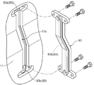
- FIG. 5 It is sectional drawing which shows one of the embodiment of the vehicle drive device which concerns on this invention. It is an enlarged view which expands and shows the supply oil path and discharge oil path in FIG. It is a schematic diagram of the oil-path bracket attached to the partition.
- FIG. 3 is an enlarged view corresponding to FIG. 2 in another embodiment of the present invention.
- FIG. 6 is a cross-sectional view of an oil passage bracket and a notch shown in FIG. 5.
- the vehicle drive device shown in FIG. 1 is a so-called one-motor parallel type hybrid vehicle drive device 1, and here is a rotating shaft coaxial with the engine output shaft ES of the engine E, which is shown only by the figure number.
- a rotating shaft 2 having a center X, a rotating electrical machine 3, a clutch 4, and a transmission mechanism VM shown only slightly at the right end are provided. These components are accommodated in a transmission housing 10.
- the rotary shaft 2 includes an input shaft portion 2a formed as a cylindrical shaft and an output shaft portion 2b fitted into the input shaft portion 2a.
- the input shaft portion 2a is connected to the engine output shaft ES via the damper mechanism D.
- the damper mechanism D is known per se, and connects the drive plate DP fixed to the engine output shaft ES and the input shaft portion 2a via a coil spring disposed along the circumferential direction.
- the coil spring is compressed to absorb the torsional impact applied to the input shaft portion 2a.
- the power transmission between the input shaft portion 2a and the output shaft portion 2b is switched between a connected state where the power can be transmitted by the clutch 4 and a disconnected state where the power cannot be transmitted.
- the output shaft portion 2b can directly receive the rotation output of the rotating electrical machine 3.
- the rotational power of the engine and / or the rotating electrical machine 3 transmitted to the output shaft portion 2b is transmitted to the front wheels and / or rear wheels of the vehicle via the speed change mechanism VM and a differential mechanism (not shown).
- the clutch 4 includes a clutch housing 50 and a wet multi-plate clutch mechanism 40 disposed inside the housing 50.
- the clutch housing 50 includes a flange-shaped member 51 having a boss hole through which the input shaft portion 2a passes, a disk member 52 with a peripheral wall, and a boss member 53 having a boss hole through which the output shaft portion 2b passes.
- the hook-shaped member 51 creates an outer peripheral wall of the clutch housing 50 and a first side wall of the clutch housing 50, and the disk member 52 with the peripheral wall and the boss member 53 are clutched.
- the second side wall of the housing 50 is created.
- a first bearing (here, a ball) is formed between the outer peripheral surface of the boss portion 51 a protruding outward from the flange-like member 51 and the boss-like axial protrusion portion 11 a protruding in the axial direction of the first partition 11 of the transmission housing 10.
- a bearing 61 is arranged to rotatably support the bowl-shaped member 51.
- a second bearing (here, a needle bearing) 62 is provided between the inner peripheral surface of the boss 51a formed at the radially inner end of the bowl-shaped member 51 and the input shaft 2a, and the input shaft 2a (rotary shaft). 2) is arranged to support the rotation.
- the bowl-shaped member 51 is supported so as to be relatively rotatable around the rotation axis X with respect to the first partition wall 11 and the input shaft portion 2a.
- the disk member 52 with a peripheral wall is connected to the end of the peripheral wall of the bowl-shaped member 51 in the vicinity of the outer peripheral edge of the disk-shaped part.
- the boss member 53 is connected to the disk member 52 with a peripheral wall at the tip of the radial protrusion flange portion.
- the boss member 53 is spline-coupled with the output shaft portion 2b on the inner peripheral surface of the boss.
- a boss portion 12 a is formed at the radially inner end of the second partition wall 12 of the transmission housing 10.
- a third bearing 63 (here, a needle bearing) 63 is disposed between the boss outer peripheral surface of the boss member 53 and the boss portion 12 a of the second partition wall 12.
- the wet multi-plate clutch mechanism 40 includes an input side member 41, a piston 42, a spring that applies a biasing force to the piston 42, a plurality of inner friction plates, and a plurality of outer friction plates.
- the input side member 41 is fixed to the input shaft portion 2a.
- the piston 42 is slidably supported on the peripheral wall of the disk member 52 with a peripheral wall of the clutch housing 50.
- the plurality of inner friction plates are incorporated in the input side member 41 so as to be movable in the axial direction.
- the plurality of outer friction plates are incorporated in the inner peripheral surface of the peripheral wall portion extending in the axial direction of the disk member 52 with the peripheral wall so as to be interposed between the inner friction plates while being movable in the axial direction.
- the disk member 52 with a peripheral wall of the clutch housing 50 and the boss member 53 constitute an output side member of the wet multi-plate clutch mechanism 40.
- a hydraulic chamber in which an oil passage formed in the boss member 53 is opened is formed between the piston 42 and the disk member 52 with a peripheral wall.
- the rotating electrical machine 3 that functions as a motor and / or generator is configured as a brushless DC motor.
- the annular stator 3 a is fixed to the inner peripheral wall of the transmission housing 10.
- the cylindrical rotor 3b that rotates about the rotation axis X is supported by being fitted on the outer peripheral surface of the clutch housing 50, more specifically, the peripheral wall portion of the flange-shaped member 51. Therefore, the clutch housing 50 or the hook-shaped member 51 functions as a rotor support member that supports the rotor 3b.
- the inner peripheral wall of the transmission housing 10 that fixes the stator 3a forms a motor case that houses the rotating electrical machine 3 together with the first partition wall 11 and the second partition wall 12 that extend from the inner peripheral wall toward the rotary shaft 2. Yes.
- the clutch housing 50 is also accommodated in the space created by the motor case, that is, in the accommodating space of the rotating electrical machine 3. That is, the clutch housing space for housing the clutch and the rotating electrical machine housing space for housing the rotating electrical machine 3 are configured in a nested manner.
- the stator 3 a is configured by winding a coil around a stator iron core made of a laminated plate fixed to the inner peripheral wall of the transmission housing 10.
- a shielding plate for shielding leakage magnetic flux is provided around the coil.
- the rotor 3b is configured by a laminated plate in which permanent magnets are embedded, and the outer peripheral surface thereof is opposed to the inner peripheral surface of the stator 3b with a predetermined gap.
- the axial protrusion 11a of the first partition 11 protrudes toward the rotating electrical machine 3 to create a boss-like region, and the rotational position of the rotor 3b is detected at a location radially outside the axial protrusion 11a.
- a rotation sensor (resolver) RS is arranged.
- the rotating electrical machine 3 when a current is supplied to a coil of the stator 3a from a power storage device (not shown) such as a battery under the control of a controller (not shown), the rotor 3b rotates, and the bowl-shaped member 51 and a circle with a peripheral wall When the plate member 52 and the boss member 53, that is, the clutch housing 50 are interlocked, the motor operates as a motor that rotates the output shaft portion 2b.
- the rotating electrical machine 3 can also operate as a generator that charges the power storage device by rotating the rotor 3b via the clutch mechanism 40 and the clutch housing 50 by the driving force of the engine E.
- the space formed between the outer peripheral surface of the boss portion 51 a of the flange-shaped member 51 constituting the clutch housing 50 and the inner peripheral surface of the axial protruding portion 11 a of the first partition wall 11 is One bearing 61 is arranged.
- the boss portion 51a of the flange-like member 51 that is a member on the clutch housing 50 side and the axial protrusion 11a that is a member on the first partition wall side are provided across the portion extending toward the clutch housing.
- the 1st seal member 71 is provided over the lower end part which faced the input shaft part 2a of the 1st partition 11 located in the engine E side of the 2nd bearing 62, and the said input shaft part 2a.
- a first oil chamber 81 is created between the first seal member 71 and one side end of the first bearing 61 (side end on the engine side), and the second seal member 72 and the first bearing 61
- a second oil chamber 82 is created between the other side end (side end on the housing side).
- the first oil chamber 81 is bounded by the first partition wall 11, the boss portion 51 a of the clutch housing 50, the input shaft portion 2 a, the first bearing 61, the second bearing 62, and the first seal member 71.
- the second oil chamber 82 is bounded by the axial protruding portion 11 a of the first partition 11, the boss portion 51 a of the clutch housing 50, the first bearing 61, and the second seal member 72.
- the first oil chamber 81 is a space portion that extends from the vicinity of the first seal member 71 and contacts one side end of the first bearing 61 facing the engine side
- the second oil chamber 82 is a second seal. It is a space portion that extends from the vicinity of the member 72 and contacts the other side end of the first bearing 61 facing the clutch housing side.
- a third seal member 73 is provided across the boss portion 12a of the second partition wall 12 and the boss member 53 of the clutch housing 50 also on the rotating electrical machine 3 side of the third bearing 63, that is, on the clutch housing 50 side.
- the supplied oil is supplied to the first oil chamber 81 through the second bearing 62.
- the oil supplied to the first oil chamber 81 enters the second oil chamber 82 through the first bearing 61.
- the oil that has entered the second oil chamber 82 is discharged to an appropriate portion inside the transmission housing 10 through a discharge oil passage 83 described in detail below.
- the discharge oil passage 83 includes a through hole as an oil passage 83a provided in the first partition 11 so as to open to the second oil chamber 82, an oil passage 83c provided in a wall body of the transmission housing 10, and an oil passage
- the oil passage 83b extends along the first partition wall 11 in the radial direction of the rotation axis X.
- the oil passage 83 b is formed in the oil passage bracket 9 attached to the outer surface of the first partition wall 11.
- the oil passage bracket 9 is attached to the first partition wall 11 using a mounting bolt 9a.
- the oil passage 83a and the oil passage 83b communicate with each other, and the oil passage 83c and the oil passage 83b communicate with each other, and a discharge oil passage 83 for discharging oil from the second oil chamber 82 is created.
- the first bearing 61 is disposed in a space created by sealing between the relatively rotating members with the first seal member 71 and the second seal member 72. Has been. Then, oil is supplied through the supply oil passage 80 to the first oil chamber 61 that is in contact with the side end on the engine side of the first bearing 61 in the space, passes through the first bearing 61, and the side end on the clutch side of the first bearing 61. Oil reaching the second oil chamber 62 in contact with the oil is discharged through a discharge oil passage 83. Thereby, the 1st bearing 61 is lubricated favorably with the flowing oil.
- the oil passage 83b that constitutes the discharge oil passage 83 that discharges the oil that has lubricated the first bearing 61 is formed in the oil passage bracket 9 that is mounted on the outer surface of the first partition wall 11.
- a notch 11 b is formed in the first partition wall 11, and an oil path 83 b is formed in the oil path bracket 90 inserted in the notch 11 b.
- This notch 11b is substantially linear in the radial direction of the rotation axis X from the region facing the second oil chamber 62 in the first partition wall 11 to the region facing the oil passage 83c provided in the wall of the transmission housing 10.
- the contour cross-sectional shape of the notch 11 b has a stepped shape in which the inner surface side is smaller than the outer surface side, and the stepped surface of the stepped shape functions as a mounting surface for the oil path bracket 90. is doing.
- the step portion of the notch 11b and both end portions of the oil passage bracket 90 are expanded in both lateral directions, and each of the planar views has substantially the same elongated H shape.
- the oil passage bracket 90 is constituted by a two-part body, and a groove is formed on one side thereof to create the main part of the oil passage 83b.
- a communication hole is provided in the center of the step portion extended in both lateral directions and in a corresponding portion of the oil passage bracket 90.
- a similar communication hole is also provided for communicating an oil passage 83c provided in the wall of the transmission housing 10 with a groove formed in the oil passage bracket 90.
- Fixing bolt holes for fixing the oil passage bracket 90 to the first partition wall 11 by bolts are provided at both ends of the step portion extended in the lateral direction of the notch 11b and the oil passage bracket 90 corresponding thereto.
- the present invention is such that the engine output is transmitted to the input side of the clutch 4 via the damper mechanism D, and the output of the rotating electrical machine 3 is directly transmitted to the output side of the clutch 4.
- the present invention is applied to a hybrid vehicle drive device in which the output of the clutch 4 is input to the speed change mechanism VM.
- the present invention can also be applied to other vehicle drive devices such as a hybrid vehicle drive device equipped with a torque converter. More specifically, in the hybrid drive apparatus in which the rotor 3b of the rotating electrical machine 3 is provided so as to rotate integrally with the pump impeller of the torque converter, the bearing that rotatably supports one or both of the pump impeller and the rotor is described above.
- the first bearing 61 in the embodiment is configured to be lubricated.
- the rotor 3b of the rotating electrical machine 3 is configured to be directly supported by the pump impeller, or a rotor support member provided as a separate member from the pump impeller is connected to rotate integrally with the pump impeller. can do.
- the present invention can be suitably used for a vehicle drive device including a rotating electrical machine having a rotor and a stator and a rotating shaft having a rotating shaft.
Priority Applications (2)
| Application Number | Priority Date | Filing Date | Title |
|---|---|---|---|
| EP09823458A EP2282394A1 (de) | 2008-10-31 | 2009-10-07 | Antriebsvorrichtung für ein fahrzeug |
| CN2009801223165A CN102067414A (zh) | 2008-10-31 | 2009-10-07 | 车用驱动装置 |
Applications Claiming Priority (2)
| Application Number | Priority Date | Filing Date | Title |
|---|---|---|---|
| JP2008-281928 | 2008-10-31 | ||
| JP2008281928A JP4941778B2 (ja) | 2008-10-31 | 2008-10-31 | 車両用駆動装置 |
Publications (1)
| Publication Number | Publication Date |
|---|---|
| WO2010050345A1 true WO2010050345A1 (ja) | 2010-05-06 |
Family
ID=42128711
Family Applications (1)
| Application Number | Title | Priority Date | Filing Date |
|---|---|---|---|
| PCT/JP2009/067477 WO2010050345A1 (ja) | 2008-10-31 | 2009-10-07 | 車両用駆動装置 |
Country Status (6)
| Country | Link |
|---|---|
| US (1) | US20100109461A1 (de) |
| EP (1) | EP2282394A1 (de) |
| JP (1) | JP4941778B2 (de) |
| KR (1) | KR20110014202A (de) |
| CN (1) | CN102067414A (de) |
| WO (1) | WO2010050345A1 (de) |
Cited By (1)
| Publication number | Priority date | Publication date | Assignee | Title |
|---|---|---|---|---|
| WO2012017767A1 (ja) * | 2010-08-06 | 2012-02-09 | アイシン・エィ・ダブリュ株式会社 | 車両用駆動装置 |
Families Citing this family (32)
| Publication number | Priority date | Publication date | Assignee | Title |
|---|---|---|---|---|
| JP5168598B2 (ja) * | 2010-03-31 | 2013-03-21 | アイシン・エィ・ダブリュ株式会社 | ハイブリッド駆動装置 |
| JP5471823B2 (ja) | 2010-05-21 | 2014-04-16 | 日産自動車株式会社 | 駆動力伝達装置 |
| JP2012061912A (ja) * | 2010-09-15 | 2012-03-29 | Aisin Seiki Co Ltd | ハイブリッド車両用駆動装置およびケース |
| JP2012086827A (ja) * | 2010-09-24 | 2012-05-10 | Aisin Aw Co Ltd | 車両用駆動装置 |
| JP2012086826A (ja) * | 2010-09-24 | 2012-05-10 | Aisin Aw Co Ltd | 車両用駆動装置 |
| DE102011010204A1 (de) * | 2011-02-03 | 2012-08-09 | Daimler Ag | Antriebsstrang für ein Kraftfahrzeug |
| JP5553172B2 (ja) * | 2011-02-09 | 2014-07-16 | 株式会社デンソー | 動力伝達装置 |
| JP5605653B2 (ja) * | 2011-02-24 | 2014-10-15 | アイシン・エィ・ダブリュ株式会社 | 車両用駆動装置 |
| JP5541197B2 (ja) * | 2011-02-28 | 2014-07-09 | アイシン・エィ・ダブリュ株式会社 | 車両駆動装置 |
| US8597145B2 (en) * | 2011-03-17 | 2013-12-03 | American Axle & Manufacturing, Inc. | Torque transfer unit with integrated electric drive motor |
| JP5610226B2 (ja) * | 2011-03-22 | 2014-10-22 | アイシン・エィ・ダブリュ株式会社 | 車両用駆動装置 |
| JP5310783B2 (ja) * | 2011-05-16 | 2013-10-09 | 株式会社デンソー | 動力伝達装置 |
| US9050883B2 (en) * | 2011-06-16 | 2015-06-09 | Honda Motor Co., Ltd. | Clutch for transmission |
| GB201117931D0 (en) * | 2011-10-18 | 2011-11-30 | Cummins Generator Technologies | Housing arrangement for an electrical machine |
| JP5589247B2 (ja) * | 2011-11-04 | 2014-09-17 | アイシン・エィ・ダブリュ株式会社 | 車両用駆動装置 |
| JP5425163B2 (ja) * | 2011-11-04 | 2014-02-26 | アイシン・エィ・ダブリュ株式会社 | 車両用駆動装置 |
| US9579965B2 (en) | 2012-01-31 | 2017-02-28 | Ford Global Technologies, Llc | Modular powertrain component for hybrid electric vehicles |
| JP5772844B2 (ja) | 2012-02-10 | 2015-09-02 | アイシン・エィ・ダブリュ株式会社 | ハイブリッド駆動装置 |
| CN103987555B (zh) | 2012-02-10 | 2016-06-08 | 爱信艾达株式会社 | 混合动力驱动装置 |
| US9636990B2 (en) * | 2012-09-28 | 2017-05-02 | Aisin Aw Co., Ltd. | Hybrid drive apparatus |
| KR20140105227A (ko) * | 2013-02-22 | 2014-09-01 | 현대자동차주식회사 | 하이브리드 차량용 구동장치 |
| US9438080B2 (en) * | 2013-03-08 | 2016-09-06 | Regal Beloit America, Inc. | Seal arrangement for a motor pump assembly and a motor for a pump including a seal arrangement |
| JP2016033003A (ja) * | 2014-07-29 | 2016-03-10 | アイシン・エィ・ダブリュ株式会社 | ハイブリッド駆動装置 |
| EP3213392B1 (de) * | 2014-10-31 | 2020-12-02 | GKN Automotive Limited | Elektroantrieb |
| US10320252B2 (en) * | 2014-11-10 | 2019-06-11 | Mitsubishi Electric Corporation | Rotary electric machine |
| WO2018008141A1 (ja) * | 2016-07-08 | 2018-01-11 | Gkn ドライブライン ジャパン株式会社 | 動力伝達装置 |
| JP6531133B2 (ja) * | 2017-04-27 | 2019-06-12 | 本田技研工業株式会社 | ハイブリッド車両の駆動装置 |
| DE102017215784A1 (de) * | 2017-09-07 | 2019-03-07 | Zf Friedrichshafen Ag | Getriebe für ein Kraftfahrzeug |
| EP3885176A4 (de) * | 2019-01-09 | 2022-01-12 | Aisin Corporation | Hybride antriebsvorrichtung |
| US11621610B2 (en) * | 2020-01-27 | 2023-04-04 | Caterpillar Inc. | Cooling assembly for an electric machine |
| KR102292764B1 (ko) * | 2020-02-14 | 2021-08-25 | 현대트랜시스 주식회사 | 하이브리드 차량용 동력전달장치 |
| KR102262898B1 (ko) * | 2020-05-18 | 2021-06-09 | 현대트랜시스 주식회사 | 차량용 하이브리드 장치의 윤활 구조 |
Citations (3)
| Publication number | Priority date | Publication date | Assignee | Title |
|---|---|---|---|---|
| JP2003023747A (ja) * | 2001-07-05 | 2003-01-24 | Toshiba Transport Eng Inc | 車両用電動機の軸受給油構造 |
| JP2004215393A (ja) * | 2002-12-27 | 2004-07-29 | Nissan Motor Co Ltd | 複軸多層モータのロータシール構造 |
| WO2006054661A1 (ja) | 2004-11-19 | 2006-05-26 | Aisin Aw Co., Ltd. | ハイブリッド車用駆動装置 |
Family Cites Families (3)
| Publication number | Priority date | Publication date | Assignee | Title |
|---|---|---|---|---|
| JPH07303351A (ja) * | 1994-03-11 | 1995-11-14 | Nippondenso Co Ltd | 車両用交流発電機 |
| BE1015913A3 (nl) * | 2004-02-23 | 2005-11-08 | Atlas Copco Airpower Nv | Machine met verbeterde lagersmering. |
| WO2006046308A1 (ja) * | 2004-10-29 | 2006-05-04 | Cxe Japan Co., Ltd. | 半導体基板の支持体 |
-
2008
- 2008-10-31 JP JP2008281928A patent/JP4941778B2/ja not_active Expired - Fee Related
-
2009
- 2009-10-07 KR KR1020107028037A patent/KR20110014202A/ko not_active Application Discontinuation
- 2009-10-07 CN CN2009801223165A patent/CN102067414A/zh active Pending
- 2009-10-07 WO PCT/JP2009/067477 patent/WO2010050345A1/ja active Application Filing
- 2009-10-07 EP EP09823458A patent/EP2282394A1/de not_active Withdrawn
- 2009-10-16 US US12/588,496 patent/US20100109461A1/en not_active Abandoned
Patent Citations (3)
| Publication number | Priority date | Publication date | Assignee | Title |
|---|---|---|---|---|
| JP2003023747A (ja) * | 2001-07-05 | 2003-01-24 | Toshiba Transport Eng Inc | 車両用電動機の軸受給油構造 |
| JP2004215393A (ja) * | 2002-12-27 | 2004-07-29 | Nissan Motor Co Ltd | 複軸多層モータのロータシール構造 |
| WO2006054661A1 (ja) | 2004-11-19 | 2006-05-26 | Aisin Aw Co., Ltd. | ハイブリッド車用駆動装置 |
Cited By (5)
| Publication number | Priority date | Publication date | Assignee | Title |
|---|---|---|---|---|
| WO2012017767A1 (ja) * | 2010-08-06 | 2012-02-09 | アイシン・エィ・ダブリュ株式会社 | 車両用駆動装置 |
| JP2012039763A (ja) * | 2010-08-06 | 2012-02-23 | Aisin Aw Co Ltd | 車両用駆動装置 |
| CN103026594A (zh) * | 2010-08-06 | 2013-04-03 | 爱信艾达株式会社 | 车辆用驱动装置 |
| US8678115B2 (en) | 2010-08-06 | 2014-03-25 | Aisin Aw Co., Ltd. | Vehicle drive device |
| CN103026594B (zh) * | 2010-08-06 | 2015-02-25 | 爱信艾达株式会社 | 车辆用驱动装置 |
Also Published As
| Publication number | Publication date |
|---|---|
| JP2010105615A (ja) | 2010-05-13 |
| EP2282394A1 (de) | 2011-02-09 |
| US20100109461A1 (en) | 2010-05-06 |
| JP4941778B2 (ja) | 2012-05-30 |
| CN102067414A (zh) | 2011-05-18 |
| KR20110014202A (ko) | 2011-02-10 |
Similar Documents
| Publication | Publication Date | Title |
|---|---|---|
| JP4941778B2 (ja) | 車両用駆動装置 | |
| JP5707656B2 (ja) | 車両用駆動装置 | |
| JP5255555B2 (ja) | 車両用駆動装置 | |
| JP4293263B2 (ja) | 車両用動力伝達装置 | |
| US7975571B2 (en) | Hybrid drive device | |
| JP5278774B2 (ja) | 車両用駆動装置 | |
| WO2011062265A1 (ja) | 車両用駆動装置 | |
| KR101459777B1 (ko) | 차량의 하이브리드 변속기 | |
| JP4311477B2 (ja) | ハイブリッド駆動装置 | |
| CN101390276A (zh) | 定子的固定结构以及电动车辆 | |
| JP2011213230A (ja) | ハイブリッド駆動変速装置 | |
| US20120217825A1 (en) | Vehicle drive system | |
| JP5605653B2 (ja) | 車両用駆動装置 | |
| US11745577B2 (en) | Torque converter | |
| JP5310783B2 (ja) | 動力伝達装置 | |
| JP3841102B2 (ja) | ハイブリッド車両用駆動装置 | |
| WO2012018027A1 (ja) | ハイブリッド駆動装置 | |
| JP6156425B2 (ja) | 車両の駆動装置 | |
| JP5682352B2 (ja) | 動力伝達装置 | |
| JP5261461B2 (ja) | 車両用駆動装置 | |
| JP4812312B2 (ja) | 駆動力伝達装置 | |
| JP2020173017A (ja) | 油圧クラッチ | |
| JP2013072494A (ja) | オイルポンプ装置 | |
| JP7418259B2 (ja) | 駆動装置 | |
| JP2011213231A (ja) | ハイブリッド駆動装置 |
Legal Events
| Date | Code | Title | Description |
|---|---|---|---|
| WWE | Wipo information: entry into national phase |
Ref document number: 200980122316.5 Country of ref document: CN |
|
| 121 | Ep: the epo has been informed by wipo that ep was designated in this application |
Ref document number: 09823458 Country of ref document: EP Kind code of ref document: A1 |
|
| WWE | Wipo information: entry into national phase |
Ref document number: 2009823458 Country of ref document: EP |
|
| ENP | Entry into the national phase |
Ref document number: 20107028037 Country of ref document: KR Kind code of ref document: A |
|
| NENP | Non-entry into the national phase |
Ref country code: DE |