WO2010023929A1 - 鋼矢板 - Google Patents
鋼矢板 Download PDFInfo
- Publication number
- WO2010023929A1 WO2010023929A1 PCT/JP2009/004184 JP2009004184W WO2010023929A1 WO 2010023929 A1 WO2010023929 A1 WO 2010023929A1 JP 2009004184 W JP2009004184 W JP 2009004184W WO 2010023929 A1 WO2010023929 A1 WO 2010023929A1
- Authority
- WO
- WIPO (PCT)
- Prior art keywords
- sheet pile
- flange
- steel sheet
- flat plate
- wall structure
- Prior art date
- Legal status (The legal status is an assumption and is not a legal conclusion. Google has not performed a legal analysis and makes no representation as to the accuracy of the status listed.)
- Ceased
Links
Images






Classifications
-
- E—FIXED CONSTRUCTIONS
- E02—HYDRAULIC ENGINEERING; FOUNDATIONS; SOIL SHIFTING
- E02D—FOUNDATIONS; EXCAVATIONS; EMBANKMENTS; UNDERGROUND OR UNDERWATER STRUCTURES
- E02D5/00—Bulkheads, piles, or other structural elements specially adapted to foundation engineering
- E02D5/02—Sheet piles or sheet pile bulkheads
- E02D5/03—Prefabricated parts, e.g. composite sheet piles
- E02D5/04—Prefabricated parts, e.g. composite sheet piles made of steel
Definitions
- the present invention relates to a steel sheet pile, and more particularly, to a steel sheet pile used when building a wall structure such as a river revetment, retaining wall and earth retaining in the field of civil engineering construction.
- a steel sheet pile manufactured by hot rolling includes a flange, a pair of webs disposed at both ends of the flange, and a joint disposed at the tip side of the web, and is generally a U-shaped steel sheet pile or a hat shape. It is called a steel sheet pile.
- a plurality of steel sheet piles are placed on the ground so as to be connected to each other, and a wall structure such as a river revetment, retaining wall and earth retaining is constructed.
- the wall structure is held vertically by resisting the earth pressure acting from the back of the wall structure due to the horizontal pressure by the ground applied to the base. Therefore, the steel sheet pile is required to have a rigidity that can sufficiently withstand the load that acts during placement and use.
- the width dimension is limited according to the thickness dimension of the steel sheet.
- the road bridge specifications specify that the width-thickness ratio (b / t) of the width dimension (b) to the thickness dimension (t) of the steel plate is b / t ⁇ 48.
- An object of the present invention is to provide a steel sheet pile having sufficient rigidity against buckling and excellent workability.
- the steel sheet pile of one aspect of the present invention includes a sheet pile main body portion and a joint portion formed on both side edges of the sheet pile main body portion, and at least a part of the sheet pile main body portion has a thickness dimension.
- (B) is a wide flat plate formed such that the width-thickness ratio (b / t) of the width dimension (b) is 48 or more and 96 or less, and one surface of the wide flat plate has a longitudinal direction.
- the cross-sectional secondary moment (I) is provided so as to be within the range defined by the following equations (1) and (2).
- a ⁇ b ⁇ t / 20 (1) I ⁇ b ⁇ t 3/11 ⁇ ⁇ ⁇ (2)
- ⁇ 1/2 ⁇ (8 (1 + 2 ⁇ ) -1) 2 -1
- ⁇ A / bt
- the protrusion provided on the wide flat plate functions as a stiffening material for buckling reinforcement. That is, compared to a flange without a ridge, the second moment of section of the entire sheet pile main body including the ridge increases by the amount of the ridge, so the buckling stress of the entire sheet pile main body Becomes larger and buckling is less likely to occur. Therefore, it is possible to provide sufficient rigidity against buckling at the time of placing and in service.
- the width-thickness ratio (b / t) of the wide flat plate is within the range represented by 48 ⁇ b / t ⁇ 96, it is only necessary to form one protrusion on the wide flat plate, An effect of preventing bending is obtained, and there is no need to provide a plurality of protrusions as in the conventional case. Therefore, the frictional resistance due to the protruding portion at the time of placing does not increase significantly, and a reduction in placing speed can be prevented.
- a wall structure can be constructed with a smaller number of sheets by using a wide steel sheet pile having a longer plate width than before. Alternatively, it is possible to reduce the weight of the steel sheet by using a thin steel sheet pile having a smaller thickness than the conventional one.
- the driving force can be increased to reduce the number of times of driving and shorten the construction time. As described above, excellent workability can be exhibited.
- the sheet pile main body portion may be formed of a single flat plate.
- the steel sheet pile of 1 aspect of this invention WHEREIN The said sheet pile main-body part may be formed by making several flat plates continue in the side edge.
- a steel sheet pile having a sheet pile main body formed of a single long flat plate is a so-called linear steel sheet pile.
- a steel sheet pile including a sheet pile main body formed by continuously connecting a plurality of long flat plates between side edges thereof is, for example, a U-shaped steel sheet pile or a hat-shaped steel configured by appropriately combining a flange and a web. It is a sheet pile or Z-shaped steel sheet pile.
- the ridge portion may be integrally formed on the wide flat plate. According to this configuration, it is not necessary to increase the number of steps for forming the ridges on the flat plate, compared to the case where the ridges are welded later, and an increase in manufacturing costs can be suppressed, and an inexpensive steel sheet pile can be used. Can be provided. Moreover, when the rigidity of a flat plate is improved by welding a rib or the like to the flat plate later, there is a problem that thermal deformation due to welding heat occurs on a thin flat plate having a large width-thickness ratio.
- the ridge portion when the ridge portion is integrally formed with the sheet pile main body portion by hot rolling, the ridge portion can be formed without being affected by thermal deformation.
- the ridge portion when a plurality of protrusions are formed on one flat plate by hot rolling, there is a problem that a burden on the rolling roller is increased.
- the effect of preventing the buckling of the steel sheet pile can be obtained only by forming one ridge portion, and therefore, an increase in roll load when manufacturing by hot rolling can be suppressed.
- the sheet pile main body portion includes a flange and a pair of webs continuous to both side edges of the flange, the flange is the wide flat plate,
- the surface may be a surface opposite to the neutral axis of the wall structure when a wall structure is configured by combining a plurality of the flanges and the steel sheet piles.
- the sheet pile main body portion includes a first flange, a pair or one web continuous with both or one side edge of the first flange, and a pair or one of these.
- a pair of one or two second flanges extending from the leading edge of the web in parallel and outward to the first flange, wherein the first flange or the second flange is the wide flat plate, and the one surface May be the surface of the first flange or the second flange opposite to the neutral axis of the wall structure when a plurality of the steel sheet piles are combined to form a wall structure.
- one surface on which the ridge portion is provided is a surface on the opposite side of the wall structure neutral shaft among the front and back surfaces of the flange, the first flange, or the second flange.
- the ridge is located farther from the neutral axis. Therefore, a large value of the moment of section relative to the neutral axis can be obtained, which is effective in increasing the section rigidity.
- the sheet pile main body includes a first flange, a pair of webs continuous to both side edges of the first flange, and the first edge from the leading edges of the pair of webs.
- a pair of second flanges extending parallel to the flange and extending outward, the web is the wide flat plate, and the projecting portion is a wall structure formed by combining a plurality of the steel sheet piles. May be located on the neutral axis.
- the sheet pile main body portion includes a web and a pair of flanges extending in opposite directions across the web in parallel with each other from both side edge edges of the web,
- the web may be the wide flat plate, and the protrusion may be positioned on a neutral axis of the wall structure when a plurality of the steel sheet piles are combined to form a wall structure.
- the protrusion is located on the neutral axis of the wall structure, even if the protrusion is provided, the neutral axis is not displaced, and the conventional steel sheet pile is not accompanied by a large design change.
- the wall structure can be constructed in the same manner as when using.
- the provision of a protrusion having a predetermined shape along the longitudinal direction on a wide flat plate has sufficient rigidity against buckling and has workability. Can be improved.
- FIG. 5A is a cross-sectional view showing a hat-shaped steel sheet pile according to the second embodiment
- FIG. 5B is a cross-sectional view showing a hat-shaped steel sheet pile according to the third embodiment.
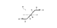
- FIG. 6A is a cross-sectional view showing a Z-shaped steel sheet pile according to the fourth embodiment
- FIG. 6B is a cross-sectional view showing a linear steel sheet pile according to the fifth embodiment. It is a cross-sectional view which shows the U-shaped steel sheet pile which concerns on the modification of this invention.
- FIG. 1 is a cross-sectional view showing a steel sheet pile (U-shaped steel sheet pile) according to the first embodiment of the present invention.
- FIG. 2 is an enlarged cross-sectional view showing a part of the U-shaped steel sheet pile.
- FIG. 3 is a cross-sectional view showing a wall structure constructed by combining a plurality of U-shaped steel sheet piles.
- a U-shaped steel sheet pile 10 is formed on both side edges of the sheet pile main body portion 11 formed from three long flat plates (flange 12 and a pair of webs 13) and the sheet pile main body portion 11. And a pair of joint portions 14 formed.
- the direction perpendicular to the plane of the paper is the longitudinal direction of the flat plate
- the direction parallel to the plane of the flat plate and perpendicular to the longitudinal direction is the width direction of the flat plate
- the direction perpendicular to the longitudinal direction and the width direction is the thickness of the flat plate. This is called the direction.
- the sheet pile main body 11 has a flange 12 located in the center and a pair of webs 13 formed continuously at both side edges in the width direction of the flange 12, and has a substantially U-shaped cross-sectional shape. I have.
- the flange 12 and the pair of webs 13 are integrally formed by hot rolling. That is, the flange 12 forms the bottom portion of the substantially U-shaped sheet pile main body portion 12, and the pair of webs 13 forms both side portions of the substantially U-shaped sheet pile main body portion 12.
- a joint portion 14 is formed in a bowl shape on the tip side of the web 13.
- FIG. 2 is an enlarged cross-sectional view of the flange 12.
- the length of the flange 12 that is orthogonal to the longitudinal direction (that is, along the width direction) is the width dimension b of the flange 12.
- the thickness dimension t and the width dimension b are set such that the width-thickness ratio (b / t) of the width dimension b to the thickness dimension t along the thickness direction of the flange 12 is in the range of 48 or more and 96 or less. Is set.
- the flange 12 constitutes the wide flat plate of the present invention.
- the protruding portion 15 is formed by combining a plurality of U-shaped steel sheet piles 10 out of either one of the front and back surfaces of the flange 12. It is provided on the surface opposite to the neutral axis P.
- the protrusion 15 is integrally formed with the flange 12 and has a substantially rectangular cross-sectional shape perpendicular to the longitudinal direction.
- the length dimension in the protruding direction (thickness direction) from the outer surface of the flange 12 is the cross-sectional protruding dimension h of the ridge portion 15.
- the length dimension along the width direction is the width dimension w of the protrusion 15.
- the protrusion 15 has a cross-sectional area A in a cross-sectional shape orthogonal to the longitudinal direction and a cross-sectional secondary moment I based on the surface on the front side of the flange defined by the following expressions (3) and (4).
- the cross-sectional shape of the protrusion 15 is set within a range that satisfies both the expressions (3) and (4).
- the following formula is set to prevent local buckling in members subjected to compressive stress based on the Road Bridge Specification / Description (Japan Road Association).
- ⁇ is a rigidity ratio of the protrusion 15 to the wide flat plate (the flange 12 in FIG. 2), and ⁇ represents a cross-sectional area ratio in a cross-sectional shape orthogonal to the longitudinal direction of the protrusion 15 to the wide flat plate.
- ⁇ 1/2 ⁇ (8 (1 + 2 ⁇ ) -1) 2 -1
- ⁇ A / bt
- the cross-sectional area A of the ridge 15 is set to be 5% or more of the cross-sectional area (b ⁇ t) of the flange 12 alone.
- the lower limit value of the sectional secondary moment I of the ridge portion 15 is set by the width dimension b and the thickness dimension t of the flange 12 and the sectional area A of the ridge portion 15. It is a value.
- FIG. 2 shows a ridge portion 15A having a width dimension w equal to the cross-sectional projection dimension h by a two-dot chain line. More preferably, the width dimension w should be suppressed to 1 ⁇ 2 times or less of the cross-sectional protrusion dimension h shown in the following formula (5).
- FIG. 2 shows another protrusion 15B having a width w that is 1 ⁇ 2 times the cross-sectional protrusion h by another two-dot chain line. w ⁇ h / 2 (5)
- the value of b ⁇ t / 20 in the formula (3) is 240
- the protrusion 15 has a sectional area A of 240 mm 2 or more, which satisfies the formula (3). is doing.
- (4) is satisfy
- FIG. 4 is a cross-sectional view showing a U-shaped steel sheet pile 10A according to a modification.
- the ridge portion 15 is formed on the back surface of the flange 12 (the inner surface of the substantially U-shaped recess).
- the protrusion part should just be provided in the surface of either the front or back of the flange 12.
- the protrusion 15 provided on the flange 12 functions as a stiffener for buckling reinforcement. That is, since the secondary moment of inertia I of the entire flange 12 including the ridge 15 is increased by the amount of the ridge 15 compared to the flange without the ridge, the seat of the sheet pile main body 11 is The bending stress is increased, and buckling is less likely to occur. Therefore, it is possible to provide sufficient rigidity against buckling at the time of placing and in service.
- the U-shaped steel sheet pile 10 can be formed only by forming one protrusion 15 on the flange 12.
- the effect of preventing buckling can be obtained, and there is no need to provide a plurality of protrusions on a single flange as in the prior art. Therefore, the frictional resistance is not significantly increased by the protrusion 15 at the time of placing, and a reduction in placing speed can be prevented.
- the driving force at the time of construction can be increased to reduce the number of times of placing, shortening the construction time, and the workability can be improved.
- the ridge portion 15 is integrally formed with the sheet pile main body portion 11 by hot rolling, the ridge portion 15 is provided on the flange 12 as compared with the case where the ridge portion 15 is welded to the flange 12 later. There is no need to increase the number of steps for forming, and an increase in manufacturing cost can be suppressed.
- the thin flange 12 having a large width-thickness ratio (b / t) undergoes thermal deformation due to welding heat. There is a problem of end.
- the protrusion part 15 is integrally formed with the sheet pile main-body part 11 by hot rolling, the protrusion part 15 can be formed without being influenced by thermal deformation.
- FIG. 5A is a cross-sectional view showing a hat-shaped steel sheet pile 20 according to the present embodiment.
- the difference between the U-shaped steel sheet pile 10 and the hat-shaped steel sheet pile 20 of the first embodiment is that, in the hat-shaped steel sheet pile 20, a second flange 24 is further extended at the tip edges of the pair of webs 23, and the sheet pile main body
- the part 21 has a hat-shaped cross-sectional shape.
- the sheet pile main-body part 21 is following the 1st flange 22, the side edge of both of this 1st flange 22, and a pair of mountain-shaped webs 23 which the front-end
- the pair of webs 23 have a pair of second flanges 24 that extend parallel to the first flange 22 and outward from the leading edge of the pair of webs 23, and a protrusion 26 is formed at a substantially central position in the width direction of the first flange 22. ing. That is, the first flange 22 corresponds to the wide flat plate of the present invention.
- the thickness dimension t and the width dimension b of the first flange 22 are set so that the width-thickness ratio (b / t) of the width dimension b to the thickness dimension t is in the range of 48 to 96. Yes.
- a joint portion 25 is provided on the distal end side of the pair of second flanges 24.
- the protruding portion 26 is provided on a surface on either side of the first flange 22 on the opposite side to the neutral axis P of the wall structure. Moreover, the cross-sectional shape orthogonal to the elongate direction of the protrusion part 26 is a substantially rectangular shape, and is the range which satisfy
- the following effects can be achieved. (11) Since the surface of the first flange 22 where the ridges 26 are provided is the surface opposite to the neutral axis P of the wall structure, the ridges 26 are located farther from the neutral axis P. Therefore, a large value of the cross-sectional secondary moment I with respect to the neutral axis P can be obtained, and the cross-sectional rigidity of the first flange 22 can be effectively increased.
- FIG. 5B is a cross-sectional view showing a hat-shaped steel sheet pile 20A according to the present embodiment.
- the difference between the hat-shaped steel sheet pile 20 and the hat-shaped steel sheet pile 20 ⁇ / b> A of the second embodiment is that, in the hat-shaped steel sheet pile 20 ⁇ / b> A, the ridge portion 27 is formed at a substantially central position in the width direction of the pair of webs 23. Is a point. That is, the pair of webs 23 corresponds to the wide flat plate of the present invention.
- the thickness dimension t and the width dimension b of the pair of webs 23 are set so that the width-thickness ratio (b / t) of the width dimension b to the thickness dimension t is in the range of 48 to 96. Yes.
- the cross-sectional shape orthogonal to the elongate direction of the protrusion part 27 is a substantially rectangular shape, and is in the range which satisfy
- the ridge portion 27 is located on the neutral axis P of the wall structure. Specifically, the protruding portion 27 is arranged with respect to the neutral shaft so that the neutral shaft P bisects the area of the substantially rectangular shape.
- the ridges 27 are formed to protrude inwardly on the inner surface of each web 23 (the inner surface of the hat-shaped recess), but the ridges 27 are formed on the outer side of each web 23. It may be formed to protrude outward on the surface (the surface opposite to the inner surface of the hat-shaped recess).
- the protrusions 27 are located on the neutral axis P of the wall structure, even if the protrusions 27 are provided on the pair of webs 23, the neutral axis P is not displaced, and no major design change is involved. . Therefore, a wall structure can be constructed as in the case of using a conventional hat-shaped steel sheet pile.
- FIG. 6A is a cross-sectional view showing a Z-shaped steel sheet pile 30 according to the present embodiment.
- the difference between the hat-shaped steel sheet pile 20A and the Z-shaped steel sheet pile 30 of the third embodiment is that the Z-shaped steel sheet pile 30 of the present embodiment has a cross-sectional shape in which the sheet pile main body portion 21 of the hat-shaped steel sheet pile 20A is substantially halved. It is a point provided with the sheet pile main-body part 31 which has.
- the differences will be described in detail.
- the sheet pile main body 31 includes a web 32, a first flange 33 and a second flange 34 that extend in parallel to each other from both side edges of the web 32 and in opposite directions across the web 32. have.
- a protrusion 36 is formed at a substantially central position in the width direction of the web 32. That is, the pair of webs 32 corresponds to the wide flat plate of the present invention.
- the thickness dimension t and the width dimension b of the pair of webs 32 are set so that the width-thickness ratio (b / t) of the width dimension b to the thickness dimension t is in the range of 48 or more and 96 or less. Yes.
- the cross-sectional shape orthogonal to the elongate direction of the protrusion part 36 is a substantially rectangular shape, and is the range which satisfy
- the protrusion part 36 is located on the neutral axis
- the protruding portion 36 is arranged with respect to the neutral shaft so that the neutral shaft P bisects the substantially rectangular area. .
- FIG. 6B is a cross-sectional view showing the linear steel sheet pile 40 according to the present embodiment.
- the straight steel sheet pile 40 includes a sheet pile main body portion 41 formed by one long flange (flat plate) 42 and a joint portion 43 formed at both side edges of the flange 42.
- the protrusion 44 is formed in the approximate center position in the width direction of the flange 42. That is, the flange 42 corresponds to the wide flat plate of the present invention.
- the flange 42 has the thickness dimension t and the width dimension b set so that the width-thickness ratio (b / t) of the width dimension b to the thickness dimension t is in the range of 48 to 96.
- the cross-sectional shape orthogonal to the longitudinal direction of the ridge 44 is substantially rectangular, and is set within a range that satisfies all of the expressions (3) and (4), like the ridge 15. According to this embodiment, the same effects as described above can be obtained.
- this invention is not limited to the said embodiment, Including other structures etc. which can achieve the objective of this invention, the deformation
- the steel sheet pile of this invention has at least 1 elongate flat plate.
- the sheet pile main body part formed including one or more sheets and a steel sheet pile provided with joint parts formed on both side edges of the sheet pile main body part may be used, and the form is not particularly limited.
- a flange was a wide flat plate of this invention among the sheet pile main-body parts in 1st Embodiment
- a steel sheet pile of this invention at least one part among sheet pile main-body parts.
- the protrusions are provided on (for example, at least one of the flange or the pair of webs).
- the ridges may be provided on all of the flange or the pair of webs.
- the first flange and the second flange may be provided with protrusions.
- the sheet pile main body portion is configured by combining a plurality of flat plates, it is only necessary that the protrusions are provided on at least a part (at least one flat plate) of the sheet pile main body portions.
- the cross-sectional shape orthogonal to the longitudinal direction of the protrusion is not limited to a substantially rectangular shape, and may be, for example, a substantially semicircular shape, a substantially semielliptical shape, or a polygon such as a triangle.
- the cross-sectional view of the U-shaped steel sheet pile 10B which concerns on the modification of this invention in FIG. 7 is shown.
- This U-shaped steel sheet pile 10B has a protrusion 16 having a substantially semicircular cross section. About the formation location and cross-sectional area of the ridge part 16, and a cross-sectional secondary moment, it is the same as the U-shaped steel sheet pile 10 of 1st Embodiment.
- the protrusions are not limited to those integrally formed on the flange or the like by hot rolling, but may be those retrofitted by welding on the flange or the like.
- the provision of a protrusion having a predetermined shape along the longitudinal direction on a wide flat plate has sufficient rigidity against buckling and has workability. Can be improved.
Landscapes
- Engineering & Computer Science (AREA)
- Structural Engineering (AREA)
- Chemical & Material Sciences (AREA)
- Composite Materials (AREA)
- Life Sciences & Earth Sciences (AREA)
- General Life Sciences & Earth Sciences (AREA)
- Mining & Mineral Resources (AREA)
- Paleontology (AREA)
- Civil Engineering (AREA)
- General Engineering & Computer Science (AREA)
- Bulkheads Adapted To Foundation Construction (AREA)
Abstract
本発明の鋼矢板は、矢板本体部と、前記矢板本体部の両方の側端縁に形成された継手部と、を備える。前記矢板本体部のうち少なくとも一部は、厚さ寸法(t)に対する幅寸法(b)の幅厚比(b/t)が48以上、96以下となるように形成された幅広平板である。この幅広平板の一方の面には、長尺方向に沿って延びる突条部が設けられる。前記突条部は、前記長尺方向に直交する断面形状における当該突条部の断面積(A)および前記一方の面を基準とする当該突条部の断面二次モーメント(I)が、次の式(1)および式(2)で定められた範囲内となるように設けられている。 A≧b・t/20 ・・・(1) I≧b・t3 /11・γ ・・・(2) ここで、γ=1/2・(8(1+2δ)-1)2-1 δ=A/bt
Description
本発明は、鋼矢板に関し、特に、土木建築分野における河川護岸,擁壁および土留めなどの壁構造を構築する際に使用される鋼矢板に関する。 本願は、2008年8月29日に、日本に出願された特願2008-222562号に基づき優先権を主張し、その内容をここに援用する。
熱間圧延で製造される鋼矢板は、フランジと、フランジの両端に配置される一対のウェブと、前記ウェブの先端側に配置される継手とを備えており、一般にU形鋼矢板やハット形鋼矢板と呼ばれている。複数の鋼矢板が互いに連結するように地盤に打設され、河川護岸,擁壁および土留めなどの壁構造を構築する。根入れ部にかかる地盤による水平方向の圧力によって、壁構造背面から作用する土圧に対して抵抗して壁構造が垂直保持される。そのため、鋼矢板には、打設時および使用時に作用する負荷に十分耐え得る剛性が求められる。鋼矢板を構成するフランジ等の圧縮力を受ける鋼板の座屈防止を目的として、鋼板の厚さ寸法に応じて幅寸法が制限されている。例えば、道路橋示方書には、鋼板の厚さ寸法(t)に対する幅寸法(b)の幅厚比(b/t)が、b/t≦48となるように規定されている。
しかし、近年、鋼矢板の打設時の施工性を高めるために、より幅厚比の大きいフランジ等で構成した鋼矢板の要求が高くなっている。例えば、より少ない枚数の鋼矢板で壁構造を構築できるように従来よりも幅寸法を長くした幅広の鋼矢板や、単体での軽量化を図るために従来よりも厚さ寸法を薄くした薄肉の鋼矢板などが求められている。
このような幅広または薄肉の鋼矢板には、座屈に対して十分な剛性を具備させるために何らかの座屈防止策を施す必要がある。例えば、U形鋼矢板のフランジの両面に突起を等間隔に設置して剛性を向上させる技術が提案されている(特許文献1参照)。
このような幅広または薄肉の鋼矢板には、座屈に対して十分な剛性を具備させるために何らかの座屈防止策を施す必要がある。例えば、U形鋼矢板のフランジの両面に突起を等間隔に設置して剛性を向上させる技術が提案されている(特許文献1参照)。
しかしながら、前記特許文献1に記載の鋼矢板では、フランジの両面に多数の突起が設置されるので、フランジの表面積が増えて、粘着性地盤内に打設する際のフランジ表面の摩擦抵抗が増大する。このため、打設スピードが低下し、幅厚比を大きくしても十分な施工性の改善が得られないという問題がある。
本発明の目的は、座屈に対して十分な剛性を具備し、かつ、施工性に優れた鋼矢板を提供することである。
本発明の一態様の鋼矢板は、矢板本体部と、前記矢板本体部の両方の側端縁に形成された継手部と、を備え、前記矢板本体部のうち少なくとも一部は、厚さ寸法(t)に対する幅寸法(b)の幅厚比(b/t)が48以上、96以下となるように形成された幅広平板であり、この幅広平板の一方の面には、長尺方向に沿って延びる突条部が設けられ、前記突条部は、前記長尺方向に直交する断面形状における当該突条部の断面積(A)および前記一方の面を基準とする当該突条部の断面二次モーメント(I)が、次の式(1)および式(2)で定められた範囲内となるように設けられている。
A≧b・t/20 ・・・(1)
I≧b・t3 /11・γ ・・・(2)
ここで、γ=1/2・(8(1+2δ)-1)2-1
δ=A/bt
A≧b・t/20 ・・・(1)
I≧b・t3 /11・γ ・・・(2)
ここで、γ=1/2・(8(1+2δ)-1)2-1
δ=A/bt
この構成によれば、幅広平板に設けられた突条部が座屈補強のための補剛材として機能する。すなわち、突条部が設けられていないフランジに比べて、突条部を含んだ矢板本体部全体での断面二次モーメントが突条部の分だけ増加するので、矢板本体部全体の座屈応力が大きくなり、座屈が生じにくくなる。従って、打設時および供用時の座屈に対する十分な剛性を具備させることができる。
また、幅広平板の幅厚比(b/t)が、48≦b/t≦96で示される範囲内であれば、幅広平板に1条の突条部を形成するだけで、鋼矢板の座屈防止の効果が得られ、従来のような複数の突条部を設ける必要がなくなる。従って、打設時の突条部による摩擦抵抗の大幅な増大が生じず、打設スピードの低下を防ぐことができる。
また、従来よりも板幅を長くした幅広の鋼矢板を用いてより少ない枚数で壁構造を構築することができる。あるいは、従来よりも板厚を薄くした薄肉の鋼矢板を用いることで単体での軽量化を図ることができる。また、打込み力を大きくして打設回数を削減し、施工時間の短縮化を図ることができる。以上のように、優れた施工性を発揮させることができる。
また、幅広平板の幅厚比(b/t)が、48≦b/t≦96で示される範囲内であれば、幅広平板に1条の突条部を形成するだけで、鋼矢板の座屈防止の効果が得られ、従来のような複数の突条部を設ける必要がなくなる。従って、打設時の突条部による摩擦抵抗の大幅な増大が生じず、打設スピードの低下を防ぐことができる。
また、従来よりも板幅を長くした幅広の鋼矢板を用いてより少ない枚数で壁構造を構築することができる。あるいは、従来よりも板厚を薄くした薄肉の鋼矢板を用いることで単体での軽量化を図ることができる。また、打込み力を大きくして打設回数を削減し、施工時間の短縮化を図ることができる。以上のように、優れた施工性を発揮させることができる。
本発明の一態様の鋼矢板において、前記矢板本体部が一枚の平板で形成されてもよい。
本発明の一態様の鋼矢板において、前記矢板本体部が複数の平板をその側端縁同士で連続させて形成されてもよい。
1枚の長尺状の平板で形成された矢板本体部を備える鋼矢板とは、いわゆる直線形鋼矢板のことである。複数の長尺状の平板をその側端縁同士で連続させて形成された矢板本体部を備える鋼矢板とは、例えば、フランジおよびウェブを適宜組み合わせて構成されたU形鋼矢板、ハット形鋼矢板またはZ形鋼矢板のことである。
本発明の一態様の鋼矢板では、前記突条部は、前記幅広平板に一体形成されていてもよい。
この構成によれば、突条部を後付で溶接する場合と比べて、平板に突条部を形成するための工程を増やさずに済み、製造コストの上昇を抑えられ、安価な鋼矢板を提供することができる。
また、平板にリブなどを後付で溶接して平板の剛性を向上させる場合、幅厚比の大きな薄肉の平板に対して、溶接熱による熱変形が生じてしまうという問題がある。これに対して、突条部を熱間圧延にて矢板本体部と一体形成する場合には、熱変形の影響を受けずに突条部を形成することができる。
ところで、1枚の平板に複数の突条部を熱間圧延にて形成する場合、圧延ローラに対する負担が大きくなるという問題がある。本発明によれば、1条の突条部を形成するだけで、鋼矢板の座屈防止の効果が得られるので、熱間圧延にて製造する際のロール負荷の増加を抑えることができる。
この構成によれば、突条部を後付で溶接する場合と比べて、平板に突条部を形成するための工程を増やさずに済み、製造コストの上昇を抑えられ、安価な鋼矢板を提供することができる。
また、平板にリブなどを後付で溶接して平板の剛性を向上させる場合、幅厚比の大きな薄肉の平板に対して、溶接熱による熱変形が生じてしまうという問題がある。これに対して、突条部を熱間圧延にて矢板本体部と一体形成する場合には、熱変形の影響を受けずに突条部を形成することができる。
ところで、1枚の平板に複数の突条部を熱間圧延にて形成する場合、圧延ローラに対する負担が大きくなるという問題がある。本発明によれば、1条の突条部を形成するだけで、鋼矢板の座屈防止の効果が得られるので、熱間圧延にて製造する際のロール負荷の増加を抑えることができる。
本発明の一態様の鋼矢板では、前記矢板本体部は、フランジと、このフランジの両方の側端縁に連続する一対のウェブとを有し、前記フランジが前記幅広平板であり、前記一方の面は、前記フランジ、当該鋼矢板を複数組み合わせて壁構造を構成した際の当該壁構造の中立軸とは反対側の面であってもよい。
また、本発明の一態様の鋼矢板では、前記矢板本体部は、第1フランジと、この第1フランジの両方または片方の側端縁に連続する一対または一枚のウェブと、これら一対または一枚のウェブの先端縁から前記第1フランジと平行かつ外方に延びる一対または一枚の第2フランジとを有し、前記第1フランジまたは第2フランジが前記幅広平板であり、前記一方の面は、前記第1フランジまたは第2フランジの、当該鋼矢板を複数組み合わせて壁構造を構成した際の当該壁構造の中立軸とは反対側の面であってもよい。
また、本発明の一態様の鋼矢板では、前記矢板本体部は、第1フランジと、この第1フランジの両方または片方の側端縁に連続する一対または一枚のウェブと、これら一対または一枚のウェブの先端縁から前記第1フランジと平行かつ外方に延びる一対または一枚の第2フランジとを有し、前記第1フランジまたは第2フランジが前記幅広平板であり、前記一方の面は、前記第1フランジまたは第2フランジの、当該鋼矢板を複数組み合わせて壁構造を構成した際の当該壁構造の中立軸とは反対側の面であってもよい。
以上の構成によれば、突条部が設けられる一方の面が、フランジ、第1フランジまたは第2フランジの表裏いずれかの面のうち、壁構造の中立軸とは反対側の面であるので、突条部が中立軸からより遠い位置となる。従って、中立軸に関する大きな断面二次モーメントの値が得られ、断面剛性を上昇させる場合に効果的である。
本発明の一態様の鋼矢板では、前記矢板本体部は、第1フランジと、この第1フランジの両方の側端縁に連続する一対のウェブと、これら一対のウェブの先端縁から前記第1フランジと平行かつ外方に延びる一対の第2フランジとを有し、前記ウェブが前記幅広平板であり、前記突条部は、当該鋼矢板を複数組み合わせて壁構造を構成した際の当該壁構造の中立軸上に位置してもよい。
また、本発明の一態様の鋼矢板では、前記矢板本体部は、ウェブと、このウェブの両方の側端縁から互いに平行かつ当該ウェブを挟んで反対方向に延びる一対のフランジとを有し、前記ウェブが前記幅広平板であり、前記突条部は、当該鋼矢板を複数組み合わせて壁構造を構成した際の当該壁構造の中立軸上に位置してもよい。
また、本発明の一態様の鋼矢板では、前記矢板本体部は、ウェブと、このウェブの両方の側端縁から互いに平行かつ当該ウェブを挟んで反対方向に延びる一対のフランジとを有し、前記ウェブが前記幅広平板であり、前記突条部は、当該鋼矢板を複数組み合わせて壁構造を構成した際の当該壁構造の中立軸上に位置してもよい。
以上の構成によれば、突条部が、壁構造の中立軸上に位置するので、突条部を設けても中立軸のズレが発生せず、大きな設計変更を伴わずに従来の鋼矢板を用いた場合と同様に壁構造を構築することができる。
本発明の鋼矢板によれば、幅広平板に長尺方向に沿って1条の所定形状の突条部を設けたことで、座屈に対して十分な剛性を具備し、かつ、施工性を向上させることができる。
以下、本発明の各実施形態を図面に基づいて説明する。
なお、第2実施形態以降の実施形態において、第1実施形態と同じ構成部材、および同様な機能を有する構成部材には、第1実施形態の構成部材と同じ符号を付し、それらの説明を省略または簡略化する。
なお、第2実施形態以降の実施形態において、第1実施形態と同じ構成部材、および同様な機能を有する構成部材には、第1実施形態の構成部材と同じ符号を付し、それらの説明を省略または簡略化する。
〔第1実施形態〕
図1は、本発明の第1実施形態に係る鋼矢板(U形鋼矢板)を示す横断面図である。図2は、U形鋼矢板の一部を拡大して示す横断面図である。図3は、複数のU形鋼矢板を組み合わせて構築した壁構造を示す横断面図である。
図1は、本発明の第1実施形態に係る鋼矢板(U形鋼矢板)を示す横断面図である。図2は、U形鋼矢板の一部を拡大して示す横断面図である。図3は、複数のU形鋼矢板を組み合わせて構築した壁構造を示す横断面図である。
図1において、U形鋼矢板10は、3枚の長尺状の平板(フランジ12、一対のウェブ13)から形成された矢板本体部11と、矢板本体部11の両方の側端縁に形成された一対の継手部14とを有して構成されている。以下、図1において紙面に直交する方向を平板の長尺方向、平板の面と平行かつ長尺方向に直交する方向を平板の幅方向、長尺方向および幅方向に直交する方向を平板の厚さ方向と称する。
矢板本体部11は、中央に位置するフランジ12と、このフランジ12の幅方向における両方の側端縁にそれぞれ連続して形成された一対のウェブ13とを有し、略U字形の断面形状を備えている。フランジ12および一対のウェブ13は、熱間圧延で一体形成される。すなわち、フランジ12が略U字状の矢板本体部12の底部を形成し、一対のウェブ13が略U字状の矢板本体部12の両側部を形成している。なお、ウェブ13の先端側に、継手部14が鉤状に形成されている。
図2は、フランジ12を拡大して示す横断面図である。
図2に示すように、フランジ12は、長尺方向に直交する(すなわち、幅方向に沿った)長さ寸法が、当該フランジ12の幅寸法bとされている。そしてフランジ12の厚さ方向に沿った厚さ寸法tに対する幅寸法bの幅厚比(b/t)が48以上、96以下の範囲内となるように、厚さ寸法tおよび幅寸法bが設定されている。本実施形態では、フランジ12が本発明の幅広平板を構成する。
図2に示すように、フランジ12は、長尺方向に直交する(すなわち、幅方向に沿った)長さ寸法が、当該フランジ12の幅寸法bとされている。そしてフランジ12の厚さ方向に沿った厚さ寸法tに対する幅寸法bの幅厚比(b/t)が48以上、96以下の範囲内となるように、厚さ寸法tおよび幅寸法bが設定されている。本実施形態では、フランジ12が本発明の幅広平板を構成する。
フランジ12の幅方向における略中央には、外側の面(略U字形の凹部の内側面とは反対側の面)から外向きに突出するとともに、長尺方向に沿って延びる1条の突条部15が形成されている。言い換えると、突条部15は、フランジ12の表裏いずれか一方の面のうち、図3に示すように、U形鋼矢板10を複数組み合わせて壁構造1を構成した際の当該壁構造1の中立軸Pとは反対側となる面に設けられている。
突条部15は、矢板本体部11が熱間圧延にて製造される際に、フランジ12に一体形成され、長尺方向と直交する断面形状が略矩形である。
図2に示すように、突条部15では、フランジ12の外側の面からの突出方向(厚さ方向)の長さ寸法が、当該突条部15の断面突出寸法hとされ、フランジ12の幅方向に沿った長さ寸法が、当該突条部15の幅寸法wとされている。
突条部15は、長尺方向に直交する断面形状における断面積A、および、フランジの表側の面を基準とする断面二次モーメントIが、次の式(3),式(4)で定められた範囲内となるように設けられている。すなわち、突条部15の断面形状は、式(3),式(4)の両方を満たす範囲内に設定されている。以下の式は、道路橋示方書・同解説(社団法人 日本道路協会)に基づき、圧縮応力受ける部材において局部座屈を防止するために設定されたものである。γは突条部15の幅広平板(図2中のフランジ12)に対する剛比であり、δは突条部15の幅広平板に対する長尺方向に直交する断面形状における断面積比を表す。
A≧b・t/20 ・・・(3)
I≧b・t3 /11・γ ・・・(4)
ここで、γ=1/2・(8(1+2δ)-1)2-1
δ=A/bt
図2に示すように、突条部15では、フランジ12の外側の面からの突出方向(厚さ方向)の長さ寸法が、当該突条部15の断面突出寸法hとされ、フランジ12の幅方向に沿った長さ寸法が、当該突条部15の幅寸法wとされている。
突条部15は、長尺方向に直交する断面形状における断面積A、および、フランジの表側の面を基準とする断面二次モーメントIが、次の式(3),式(4)で定められた範囲内となるように設けられている。すなわち、突条部15の断面形状は、式(3),式(4)の両方を満たす範囲内に設定されている。以下の式は、道路橋示方書・同解説(社団法人 日本道路協会)に基づき、圧縮応力受ける部材において局部座屈を防止するために設定されたものである。γは突条部15の幅広平板(図2中のフランジ12)に対する剛比であり、δは突条部15の幅広平板に対する長尺方向に直交する断面形状における断面積比を表す。
A≧b・t/20 ・・・(3)
I≧b・t3 /11・γ ・・・(4)
ここで、γ=1/2・(8(1+2δ)-1)2-1
δ=A/bt
式(3)に示すように、突条部15の断面積Aは、フランジ12単独での断面積(b・t)の5%の面積以上となるように設定されている。また、式(4)に示すように、突条部15の断面二次モーメントIの下限値は、フランジ12の幅寸法b、厚さ寸法tおよび突条部15の断面積Aによって設定される値となっている。
また、図2にて実線で示すように、突条部15の断面当たりの重量を抑えるために、当該突条部15の幅寸法wを断面突出寸法hの2倍以下に抑えることが好ましい。より好ましくは、幅寸法wを断面突出寸法hと同等以下に抑えた方がよい。図2に断面突出寸法hに等しい幅寸法wを有する突条部15Aを2点鎖線で示す。更に好ましくは、幅寸法wを次の式(5)に示す断面突出寸法hの1/2倍以下に抑えた方がよい。図2に断面突出寸法hの1/2倍の幅寸法wを有する突条部15Bを別の2点鎖線で示す。
w≦h/2 ・・・(5)
w≦h/2 ・・・(5)
以上のような突条部15の断面突出寸法hおよび幅寸法wの具体的な数値について、b=480mm,t=10mmの幅広平板を使用した場合を例に、表1に示す。この幅広平板では式(3)中のb・t/20の値が240となるの対して、突条部15は、その断面積Aが240mm2以上となっており、式(3)を満足している。下表のように、h=80,w=40またはh=85,w=11またはh=90,w=8などの断面突出寸法hおよび幅寸法wの組合せは、いずれも、式(3)及び(4)を満たし、尚且つ式(5)をも満たしている。

ここで、本実施形態の変形例のU形鋼矢板について図4に基づいて説明する。
図4は、変形例に係るU形鋼矢板10Aを示す横断面図である。U形鋼矢板10Aでは、フランジ12の裏側の面(略U字形の凹部の内側面)に前記突条部15が形成されている。このように、本発明の鋼矢板としては、フランジ12の表裏いずれか一方の面に、突条部が設けられていればよい。
図4は、変形例に係るU形鋼矢板10Aを示す横断面図である。U形鋼矢板10Aでは、フランジ12の裏側の面(略U字形の凹部の内側面)に前記突条部15が形成されている。このように、本発明の鋼矢板としては、フランジ12の表裏いずれか一方の面に、突条部が設けられていればよい。
本実施形態によれば、次のような効果を奏することができる。
(1)フランジ12に設けられた突条部15が座屈補強のための補剛材として機能する。すなわち、突条部が設けられていないフランジに比べて、突条部15を含んだフランジ12全体での断面二次モーメントIが突条部15の分だけ増加するので、矢板本体部11の座屈応力が大きくなり、座屈が生じにくくなる。従って、打設時および供用時の座屈に対する十分な剛性を具備させることができる。
(1)フランジ12に設けられた突条部15が座屈補強のための補剛材として機能する。すなわち、突条部が設けられていないフランジに比べて、突条部15を含んだフランジ12全体での断面二次モーメントIが突条部15の分だけ増加するので、矢板本体部11の座屈応力が大きくなり、座屈が生じにくくなる。従って、打設時および供用時の座屈に対する十分な剛性を具備させることができる。
(2)フランジ12の幅厚比(b/t)が、48≦b/t≦96の範囲内であれば、フランジ12に突条部15を1条形成するだけで、U形鋼矢板10の座屈防止の効果が得られ、従来のような1枚のフランジに複数の突条部を設ける必要がなくなる。従って、打設時の突条部15による摩擦抵抗の大幅な増大が生じず、打設スピードの低下を防止できる。
(3)従来よりもフランジ12の幅寸法bを長くした幅広のU形鋼矢板10を形成しても、座屈に対する十分な剛性を具備させることができるので、より少ない枚数のU形鋼矢板10で壁構造1を構築することができ、施工性が向上される。
(4)従来よりもフランジ12の厚さ寸法tを薄くした薄肉のU形鋼矢板10を形成しても、座屈に対する十分な剛性を具備させることができるので、U形鋼矢板10単体での軽量化を図ることができ、施工性が向上される。
(5)施工時の打込み力を大きくして打設回数を削減し、施工時間の短縮化を図ることができ、施工性が向上される。
(6)また、フランジ12に突条部15が形成されることで、矢板本体部11の曲げ剛性が増大し、打設時における水平方向の振動を抑制することができる。
(6)また、フランジ12に突条部15が形成されることで、矢板本体部11の曲げ剛性が増大し、打設時における水平方向の振動を抑制することができる。
(7)突条部15が熱間圧延にて矢板本体部11と一体形成されるので、フランジ12に突条部15を後付で溶接する場合と比べて、フランジ12に突条部15を形成するための工程を増やす必要がなく、製造コストの上昇を抑えることができる。
(8)フランジ12にリブなどを後付で溶接してフランジ12の剛性を向上させる場合、幅厚比(b/t)の大きな薄肉のフランジ12に対して、溶接熱による熱変形が生じてしまうという問題がある。これに対して、本実施形態では、突条部15が熱間圧延にて矢板本体部11と一体形成されるので、熱変形の影響を受けずに突条部15を形成することができる。
(9)1枚のフランジ12に複数の突条部を熱間圧延にて形成する場合、圧延ローラに対する負担が大きくなるという問題がある。本実施形態では、1枚のフランジ12に1条の突条部15を形成するだけで、U形鋼矢板10の座屈防止の効果が得られるので、熱間圧延にて製造する際のロール負荷の増加を抑えることができる。
(10)突条部15が設けられるフランジ12の表側の面が、壁構造1の中立軸Pとは反対側の面であるので、突条部15が中立軸Pからより遠い位置となる。従って、中立軸Pに関する大きな断面二次モーメントIの値が得られ、フランジ12の断面剛性を効果的に上昇させることができる。
〔第2実施形態〕
次に、本発明の第2実施形態に係る鋼矢板(ハット形鋼矢板)について図5Aに基づいて説明する。
図5Aは、本実施形態に係るハット形鋼矢板20を示す横断面図である。
第1実施形態のU形鋼矢板10とハット形鋼矢板20との異なる点は、ハット形鋼矢板20では、一対のウェブ23の先端縁にさらに第2のフランジ24が延設され、矢板本体部21がハット形の断面形状を有する点である。これにより、複数のハット形鋼矢板20を使用して壁構造を構築した際に、ハット形鋼矢板20単独での中立軸Pと、壁構造の中立軸Pとが一致する。以下、相違点について詳しく説明する。
次に、本発明の第2実施形態に係る鋼矢板(ハット形鋼矢板)について図5Aに基づいて説明する。
図5Aは、本実施形態に係るハット形鋼矢板20を示す横断面図である。
第1実施形態のU形鋼矢板10とハット形鋼矢板20との異なる点は、ハット形鋼矢板20では、一対のウェブ23の先端縁にさらに第2のフランジ24が延設され、矢板本体部21がハット形の断面形状を有する点である。これにより、複数のハット形鋼矢板20を使用して壁構造を構築した際に、ハット形鋼矢板20単独での中立軸Pと、壁構造の中立軸Pとが一致する。以下、相違点について詳しく説明する。
図5Aに示すように、矢板本体部21は、第1フランジ22と、この第1フランジ22の両方の側端縁に連続しており、先端が切り欠いた山形状の一対のウェブ23と、これら一対のウェブ23の先端縁から第1フランジ22と平行かつ外方に延びる一対の第2フランジ24とを有し、第1フランジ22の幅方向における略中央位置に突条部26が形成されている。すなわち、第1フランジ22が本発明の幅広平板に該当する。第1フランジ22は、その厚さ寸法tに対する幅寸法bの幅厚比(b/t)が48以上、96以下の範囲内となるように、厚さ寸法tおよび幅寸法bが設定されている。なお、一対の第2フランジ24の先端側に継手部25が設けられている。
突条部26は、第1フランジ22の表裏いずれか一方の面のうち、壁構造の中立軸Pとは反対側となる面に設けられている。また、突条部26の長尺方向に直交する断面形状は、略矩形状で、第1実施形態の突条部15と同様に、式(3),式(4)のすべてを満たす範囲内に設定されている。
このような本実施形態によれば、前述の効果と同様の効果に加えて以下の効果を奏することができる。
(11)第1フランジ22において突条部26が設けられる面が、壁構造の中立軸Pとは反対側の面であるので、突条部26が中立軸Pからより遠い位置となる。従って、中立軸Pに関する大きな断面二次モーメントIの値が得られ、第1フランジ22の断面剛性を効果的に上昇させることができる。
(11)第1フランジ22において突条部26が設けられる面が、壁構造の中立軸Pとは反対側の面であるので、突条部26が中立軸Pからより遠い位置となる。従って、中立軸Pに関する大きな断面二次モーメントIの値が得られ、第1フランジ22の断面剛性を効果的に上昇させることができる。
〔第3実施形態〕
次に、本発明の第3実施形態に係る鋼矢板(ハット形鋼矢板)について図5Bに基づいて説明する。
図5Bは、本実施形態に係るハット形鋼矢板20Aを示す横断面図である。
第2実施形態のハット形鋼矢板20とハット形鋼矢板20Aとの異なる点は、ハット形鋼矢板20Aでは、一対のウェブ23の幅方向における略中央位置に突条部27が形成されている点である。すなわち、一対のウェブ23が本発明の幅広平板に該当する。一対のウェブ23は、その厚さ寸法tに対する幅寸法bの幅厚比(b/t)が48以上、96以下の範囲内となるように、厚さ寸法tおよび幅寸法bが設定されている。
なお、突条部27の長尺方向に直交する断面形状は、略矩形状で、第1実施形態の突条部15と同様に、式(3),式(4)のすべてを満たす範囲内に設定されている。また、突条部27は、壁構造の中立軸P上に位置している。具体的には、中立軸Pが略矩形状の面積を2等分するように、突条部27が中立軸に対して配置されている。本実施形態では、突条部27は、各ウェブ23の内側の面(ハット形の凹部の内側面)に内向きに突出して形成されているが、突条部27が各ウェブ23の外側の面(ハット形の凹部の内側面とは反対側の面)に外向きに突出して形成されてもよい。
次に、本発明の第3実施形態に係る鋼矢板(ハット形鋼矢板)について図5Bに基づいて説明する。
図5Bは、本実施形態に係るハット形鋼矢板20Aを示す横断面図である。
第2実施形態のハット形鋼矢板20とハット形鋼矢板20Aとの異なる点は、ハット形鋼矢板20Aでは、一対のウェブ23の幅方向における略中央位置に突条部27が形成されている点である。すなわち、一対のウェブ23が本発明の幅広平板に該当する。一対のウェブ23は、その厚さ寸法tに対する幅寸法bの幅厚比(b/t)が48以上、96以下の範囲内となるように、厚さ寸法tおよび幅寸法bが設定されている。
なお、突条部27の長尺方向に直交する断面形状は、略矩形状で、第1実施形態の突条部15と同様に、式(3),式(4)のすべてを満たす範囲内に設定されている。また、突条部27は、壁構造の中立軸P上に位置している。具体的には、中立軸Pが略矩形状の面積を2等分するように、突条部27が中立軸に対して配置されている。本実施形態では、突条部27は、各ウェブ23の内側の面(ハット形の凹部の内側面)に内向きに突出して形成されているが、突条部27が各ウェブ23の外側の面(ハット形の凹部の内側面とは反対側の面)に外向きに突出して形成されてもよい。
このような本実施形態によれば、前述の効果と同様の効果に加えて以下の効果を奏することができる。
(12)突条部27が、壁構造の中立軸P上に位置するので、一対のウェブ23に突条部27を設けても中立軸Pのズレが発生せず、大きな設計変更を伴わない。従って、従来のハット形鋼矢板を用いた場合と同様に壁構造を構築することができる。
(12)突条部27が、壁構造の中立軸P上に位置するので、一対のウェブ23に突条部27を設けても中立軸Pのズレが発生せず、大きな設計変更を伴わない。従って、従来のハット形鋼矢板を用いた場合と同様に壁構造を構築することができる。
〔第4実施形態〕
次に、本発明の第4実施形態に係る鋼矢板(Z形鋼矢板)について図6Aに基づいて説明する。
図6Aは、本実施形態に係るZ形鋼矢板30を示す横断面図である。
第3実施形態のハット形鋼矢板20AとZ形鋼矢板30との異なる点は、本実施形態のZ形鋼矢板30は、ハット形鋼矢板20Aの矢板本体部21を略半分にした断面形状を有した矢板本体部31を備えている点である。以下、相違点について詳しく説明する。
次に、本発明の第4実施形態に係る鋼矢板(Z形鋼矢板)について図6Aに基づいて説明する。
図6Aは、本実施形態に係るZ形鋼矢板30を示す横断面図である。
第3実施形態のハット形鋼矢板20AとZ形鋼矢板30との異なる点は、本実施形態のZ形鋼矢板30は、ハット形鋼矢板20Aの矢板本体部21を略半分にした断面形状を有した矢板本体部31を備えている点である。以下、相違点について詳しく説明する。
図6Aに示すように、矢板本体部31は、ウェブ32と、このウェブ32の両方の側端縁から互いに平行かつ当該ウェブ32を挟んで反対方向に延びる第1フランジ33および第2フランジ34とを有している。このウェブ32の幅方向における略中央位置に突条部36が形成されている。
すなわち、一対のウェブ32が本発明の幅広平板に該当する。一対のウェブ32は、その厚さ寸法tに対する幅寸法bの幅厚比(b/t)が48以上、96以下の範囲内となるように、厚さ寸法tおよび幅寸法bが設定されている。
なお、突条部36の長尺方向に直交する断面形状は、略矩形状で、第3実施形態の突条部27と同様に、式(3),式(4)のすべてを満たす範囲内に設定されている。また、突条部36は、当該Z形鋼矢板30を複数組み合わせて壁構造を構成した際の壁構造の中立軸P上に位置している。具体的には、第3実施形態のハット形鋼矢板20Aと同様に、中立軸Pが略矩形状の面積を2等分するように、突条部36が中立軸に対して配置されている。
すなわち、一対のウェブ32が本発明の幅広平板に該当する。一対のウェブ32は、その厚さ寸法tに対する幅寸法bの幅厚比(b/t)が48以上、96以下の範囲内となるように、厚さ寸法tおよび幅寸法bが設定されている。
なお、突条部36の長尺方向に直交する断面形状は、略矩形状で、第3実施形態の突条部27と同様に、式(3),式(4)のすべてを満たす範囲内に設定されている。また、突条部36は、当該Z形鋼矢板30を複数組み合わせて壁構造を構成した際の壁構造の中立軸P上に位置している。具体的には、第3実施形態のハット形鋼矢板20Aと同様に、中立軸Pが略矩形状の面積を2等分するように、突条部36が中立軸に対して配置されている。
このような本実施形態によれば、前述の効果と同様の効果に加えて以下の効果を奏することができる。
(13)突条部36が、壁構造の中立軸P上に位置するので、ウェブ32に突条部36を設けても中立軸Pのズレが発生せず、大きな設計変更を伴わない。従って、従来のZ形鋼矢板を用いた場合と同様に壁構造を構築することができる。
(13)突条部36が、壁構造の中立軸P上に位置するので、ウェブ32に突条部36を設けても中立軸Pのズレが発生せず、大きな設計変更を伴わない。従って、従来のZ形鋼矢板を用いた場合と同様に壁構造を構築することができる。
〔第5実施形態〕
次に、本発明の第5実施形態に係る鋼矢板(直線形鋼矢板)について図6Bに基づいて説明する。
図6Bは、本実施形態に係る直線形鋼矢板40を示す横断面図である。
直線形鋼矢板40は、1枚の長尺状のフランジ(平板)42で形成された矢板本体部41と、フランジ42の両方の側端縁に形成された継手部43とを備えている。そして、フランジ42の幅方向における略中央位置に突条部44が形成されている。
すなわち、フランジ42が本発明の幅広平板に該当する。フランジ42は、その厚さ寸法tに対する幅寸法bの幅厚比(b/t)が48以上、96以下の範囲内となるように、厚さ寸法tおよび幅寸法bが設定されている。
突条部44の長尺方向に直交する断面形状は、略矩形状で、前記突条部15と同様に、式(3),式(4)のすべてを満たす範囲内に設定されている。
このような本実施形態によれば、前述の効果と同様の効果を奏することができる。
次に、本発明の第5実施形態に係る鋼矢板(直線形鋼矢板)について図6Bに基づいて説明する。
図6Bは、本実施形態に係る直線形鋼矢板40を示す横断面図である。
直線形鋼矢板40は、1枚の長尺状のフランジ(平板)42で形成された矢板本体部41と、フランジ42の両方の側端縁に形成された継手部43とを備えている。そして、フランジ42の幅方向における略中央位置に突条部44が形成されている。
すなわち、フランジ42が本発明の幅広平板に該当する。フランジ42は、その厚さ寸法tに対する幅寸法bの幅厚比(b/t)が48以上、96以下の範囲内となるように、厚さ寸法tおよび幅寸法bが設定されている。
突条部44の長尺方向に直交する断面形状は、略矩形状で、前記突条部15と同様に、式(3),式(4)のすべてを満たす範囲内に設定されている。
このような本実施形態によれば、前述の効果と同様の効果を奏することができる。
〔本発明に係る変形例〕
なお、本発明は、前記実施形態に限定されるものではなく、本発明の目的を達成できる他の構成等を含み、以下に示すような変形等も本発明に含まれる。
例えば、前記実施形態においては、鋼矢板としてU形鋼矢板、ハット形鋼矢板、Z形鋼矢板および直線形鋼矢板について説明したが、本発明の鋼矢板は、長尺状の平板を少なくとも1枚以上含んで形成された矢板本体部と、その矢板本体部の両方の側端縁に形成された継手部とを備える鋼矢板であればよく、その形態は特に限定されない。
なお、本発明は、前記実施形態に限定されるものではなく、本発明の目的を達成できる他の構成等を含み、以下に示すような変形等も本発明に含まれる。
例えば、前記実施形態においては、鋼矢板としてU形鋼矢板、ハット形鋼矢板、Z形鋼矢板および直線形鋼矢板について説明したが、本発明の鋼矢板は、長尺状の平板を少なくとも1枚以上含んで形成された矢板本体部と、その矢板本体部の両方の側端縁に形成された継手部とを備える鋼矢板であればよく、その形態は特に限定されない。
また、前記実施形態では、例えば第1実施形態にて矢板本体部のうちフランジが本発明の幅広平板である場合を説明したが、本発明の鋼矢板としては、矢板本体部のうち少なくとも一部(例えば、フランジまたは一対のウェブのうち少なくとも1枚)に突条部が設けられていればよい。また、フランジまたは一対のウェブのすべてに突条部が設けられていても構わない。
同様に、第4実施形態では、Z形鋼矢板のウェブが本発明の幅広平板である場合を説明したが、第1フランジおよび第2フランジに突条部が設けられていてもよい。
同様に、矢板本体部が複数の平板を組み合わせて構成された他の実施形態において、矢板本体部のうち少なくとも一部(少なくとも1枚の平板)に突条部が設けられていればよい。
同様に、第4実施形態では、Z形鋼矢板のウェブが本発明の幅広平板である場合を説明したが、第1フランジおよび第2フランジに突条部が設けられていてもよい。
同様に、矢板本体部が複数の平板を組み合わせて構成された他の実施形態において、矢板本体部のうち少なくとも一部(少なくとも1枚の平板)に突条部が設けられていればよい。
また、突条部の長尺方向と直交する断面形状は、略矩形状に限られず、例えば、略半円形状、略半楕円形状、あるいは三角形などの多角形であっても構わない。ここで、図7に本発明の変形例に係るU形鋼矢板10Bの横断面図を示す。このU形鋼矢板10Bは、断面形状が略半円形の突条部16を有している。突条部16の形成箇所および断面積、断面2次モーメントについては、第1実施形態のU形鋼矢板10と同じである。
また、突条部は、熱間圧延にてフランジなどに一体形成されたものに限られず、フランジなどに溶接にて後付けされたものでもよい。
また、突条部は、熱間圧延にてフランジなどに一体形成されたものに限られず、フランジなどに溶接にて後付けされたものでもよい。
本発明の鋼矢板によれば、幅広平板に長尺方向に沿って1条の所定形状の突条部を設けたことで、座屈に対して十分な剛性を具備し、かつ、施工性を向上させることができる。
1…壁構造
10,10A,10B…U形鋼矢板
11,21,31,41…矢板本体部
12,42…フランジ(幅広平板)
13…ウェブ(平板)
14,25,35,43…継手部
15,15A,15B,16,26,27,36,44…突条部
20,20A…ハット形鋼矢板
22…第1フランジ(幅広平板)
23,32…ウェブ(幅広平板)
24…第2フランジ(平板)
30…Z形鋼矢板
33…第1フランジ(平板)
34…第2フランジ(平板)
40…直線形鋼矢板
b…平板の幅寸法
h…断面突出寸法
t…平板の厚さ寸法
w…突出部の幅寸法
10,10A,10B…U形鋼矢板
11,21,31,41…矢板本体部
12,42…フランジ(幅広平板)
13…ウェブ(平板)
14,25,35,43…継手部
15,15A,15B,16,26,27,36,44…突条部
20,20A…ハット形鋼矢板
22…第1フランジ(幅広平板)
23,32…ウェブ(幅広平板)
24…第2フランジ(平板)
30…Z形鋼矢板
33…第1フランジ(平板)
34…第2フランジ(平板)
40…直線形鋼矢板
b…平板の幅寸法
h…断面突出寸法
t…平板の厚さ寸法
w…突出部の幅寸法
Claims (8)
- 矢板本体部と、
前記矢板本体部の両方の側端縁に形成された継手部と、を備え、
前記矢板本体部のうち少なくとも一部は、厚さ寸法(t)に対する幅寸法(b)の幅厚比(b/t)が48以上、96以下となるように形成された幅広平板であり、
この幅広平板の一方の面には、長尺方向に沿って延びる突条部が設けられ、
前記突条部は、前記長尺方向に直交する断面形状における当該突条部の断面積(A)および前記一方の面を基準とする当該突条部の断面二次モーメント(I)が、次の式(1)および式(2)で定められた範囲内となるように設けられている鋼矢板。
A≧b・t/20 ・・・(1)
I≧b・t3 /11・γ ・・・(2)
ここで、γ=1/2・(8(1+2δ)-1)2-1
δ=A/bt - 請求項1に記載の鋼矢板において、前記矢板本体部は、一枚の平板で形成される。
- 請求項1に記載の鋼矢板において、前記矢板本体部は、複数の平板をその側端縁同士で連続させて形成される。
- 請求項1に記載の鋼矢板において、
前記突条部は、前記幅広平板に一体形成されている。 - 請求項1に記載の鋼矢板において、
前記矢板本体部は、フランジと、このフランジの両方の側端縁に連続する一対のウェブとを有し、
前記フランジが前記幅広平板であり、
前記一方の面は、前記フランジの、当該鋼矢板を複数組み合わせて壁構造を構成した際の当該壁構造の中立軸とは反対側の面である。 - 請求項1に記載の鋼矢板において、
前記矢板本体部は、第1フランジと、この第1フランジの両方または片方の側端縁に連続する一対または一枚のウェブと、これら一対または一枚のウェブの先端縁から前記第1フランジと平行かつ外方に延びる一対または一枚の第2フランジとを有し、
前記第1フランジまたは第2フランジが前記幅広平板であり、
前記一方の面は、前記第1フランジまたは第2フランジの、当該鋼矢板を複数組み合わせて壁構造を構成した際の当該壁構造の中立軸とは反対側の面である。 - 請求項1に記載の鋼矢板において、
前記矢板本体部は、第1フランジと、この第1フランジの両方の側端縁に連続する一対のウェブと、これら一対のウェブの先端縁から前記第1フランジと平行かつ外方に延びる一対の第2フランジとを有し、
前記ウェブが前記幅広平板であり、
前記突条部は、当該鋼矢板を複数組み合わせて壁構造を構成した際の当該壁構造の中立軸上に位置する。 - 請求項1に記載の鋼矢板において、
前記矢板本体部は、ウェブと、このウェブの両方の側端縁から互いに平行かつ当該ウェブを挟んで反対方向に延びる一対のフランジとを有し、
前記ウェブが前記幅広平板であり、
前記突条部は、当該鋼矢板を複数組み合わせて壁構造を構成した際の当該壁構造の中立軸上に位置する。
Priority Applications (1)
| Application Number | Priority Date | Filing Date | Title |
|---|---|---|---|
| JP2010526558A JP4772925B2 (ja) | 2008-08-29 | 2009-08-27 | 鋼矢板 |
Applications Claiming Priority (2)
| Application Number | Priority Date | Filing Date | Title |
|---|---|---|---|
| JP2008-222562 | 2008-08-29 | ||
| JP2008222562 | 2008-08-29 |
Publications (1)
| Publication Number | Publication Date |
|---|---|
| WO2010023929A1 true WO2010023929A1 (ja) | 2010-03-04 |
Family
ID=41721110
Family Applications (1)
| Application Number | Title | Priority Date | Filing Date |
|---|---|---|---|
| PCT/JP2009/004184 Ceased WO2010023929A1 (ja) | 2008-08-29 | 2009-08-27 | 鋼矢板 |
Country Status (2)
| Country | Link |
|---|---|
| JP (1) | JP4772925B2 (ja) |
| WO (1) | WO2010023929A1 (ja) |
Cited By (9)
| Publication number | Priority date | Publication date | Assignee | Title |
|---|---|---|---|---|
| WO2018117269A1 (ja) * | 2016-12-22 | 2018-06-28 | Jfeスチール株式会社 | ハット形鋼矢板 |
| JP2020020258A (ja) * | 2019-10-07 | 2020-02-06 | Jfeスチール株式会社 | ハット形鋼矢板の製造方法及び設計方法 |
| WO2020045119A1 (ja) * | 2018-08-31 | 2020-03-05 | 日本製鉄株式会社 | ハット形鋼矢板 |
| WO2020045114A1 (ja) * | 2018-08-31 | 2020-03-05 | 日本製鉄株式会社 | ハット形鋼矢板および鋼矢板壁の製造方法 |
| WO2020045115A1 (ja) * | 2018-08-31 | 2020-03-05 | 日本製鉄株式会社 | ハット形鋼矢板および鋼矢板壁の製造方法 |
| WO2020045117A1 (ja) * | 2018-08-31 | 2020-03-05 | 日本製鉄株式会社 | ハット形鋼矢板および鋼矢板壁の製造方法 |
| WO2020045113A1 (ja) * | 2018-08-31 | 2020-03-05 | 日本製鉄株式会社 | ハット形鋼矢板、鋼矢板壁および鋼矢板壁の製造方法 |
| WO2020045118A1 (ja) * | 2018-08-31 | 2020-03-05 | 日本製鉄株式会社 | ハット形鋼矢板 |
| JP2020097881A (ja) * | 2018-10-19 | 2020-06-25 | ジェイ・ディー・フィールズ・アンド・カンパニー,インコーポレーテッドJ.D. Fields & Company, Inc. | 複合矢板システム |
Families Citing this family (1)
| Publication number | Priority date | Publication date | Assignee | Title |
|---|---|---|---|---|
| CN108419406B (zh) * | 2018-02-09 | 2020-01-07 | 烽火通信科技股份有限公司 | 一种通信设备机框的加固方法 |
Citations (8)
| Publication number | Priority date | Publication date | Assignee | Title |
|---|---|---|---|---|
| JPS5796127A (en) * | 1980-12-05 | 1982-06-15 | Kawasaki Steel Corp | Linear steel sheet pile |
| JPH05146801A (ja) * | 1991-11-28 | 1993-06-15 | Sumitomo Metal Ind Ltd | H形鋼矢板およびその圧延方法 |
| JPH08302673A (ja) * | 1995-04-28 | 1996-11-19 | Nkk Corp | 鋼管矢板 |
| JPH1054018A (ja) * | 1996-08-09 | 1998-02-24 | Nippon Steel Corp | ガイドパイルとエレメントセルからなる多角形筒状セルとその構築方法 |
| JP2000192447A (ja) * | 1998-12-25 | 2000-07-11 | Nkk Corp | 地中列壁用部材 |
| JP2002206234A (ja) * | 2001-01-15 | 2002-07-26 | Nippon Steel Corp | 座屈耐力向上の鋼矢板 |
| JP2002294691A (ja) * | 2001-03-29 | 2002-10-09 | Nippon Steel Corp | Z型鋼矢板 |
| JP2004332517A (ja) * | 2003-05-08 | 2004-11-25 | Hiroshi Hara | 鋼矢板 |
-
2009
- 2009-08-27 WO PCT/JP2009/004184 patent/WO2010023929A1/ja not_active Ceased
- 2009-08-27 JP JP2010526558A patent/JP4772925B2/ja active Active
Patent Citations (8)
| Publication number | Priority date | Publication date | Assignee | Title |
|---|---|---|---|---|
| JPS5796127A (en) * | 1980-12-05 | 1982-06-15 | Kawasaki Steel Corp | Linear steel sheet pile |
| JPH05146801A (ja) * | 1991-11-28 | 1993-06-15 | Sumitomo Metal Ind Ltd | H形鋼矢板およびその圧延方法 |
| JPH08302673A (ja) * | 1995-04-28 | 1996-11-19 | Nkk Corp | 鋼管矢板 |
| JPH1054018A (ja) * | 1996-08-09 | 1998-02-24 | Nippon Steel Corp | ガイドパイルとエレメントセルからなる多角形筒状セルとその構築方法 |
| JP2000192447A (ja) * | 1998-12-25 | 2000-07-11 | Nkk Corp | 地中列壁用部材 |
| JP2002206234A (ja) * | 2001-01-15 | 2002-07-26 | Nippon Steel Corp | 座屈耐力向上の鋼矢板 |
| JP2002294691A (ja) * | 2001-03-29 | 2002-10-09 | Nippon Steel Corp | Z型鋼矢板 |
| JP2004332517A (ja) * | 2003-05-08 | 2004-11-25 | Hiroshi Hara | 鋼矢板 |
Non-Patent Citations (1)
| Title |
|---|
| JAPAN ROAD ASSOCIATION, DOROKYO SHIHOSHO (1 KYOTSUHEN, 2 KOKYOHEN), DOKAISETSU, no. 3 ED., 12 December 1994 (1994-12-12), pages 140 - 141 * |
Cited By (23)
| Publication number | Priority date | Publication date | Assignee | Title |
|---|---|---|---|---|
| WO2018117269A1 (ja) * | 2016-12-22 | 2018-06-28 | Jfeスチール株式会社 | ハット形鋼矢板 |
| JP2018104889A (ja) * | 2016-12-22 | 2018-07-05 | Jfeスチール株式会社 | ハット形鋼矢板 |
| JPWO2020045119A1 (ja) * | 2018-08-31 | 2021-04-08 | 日本製鉄株式会社 | ハット形鋼矢板 |
| JPWO2020045114A1 (ja) * | 2018-08-31 | 2021-08-10 | 日本製鉄株式会社 | ハット形鋼矢板および鋼矢板壁の製造方法 |
| WO2020045114A1 (ja) * | 2018-08-31 | 2020-03-05 | 日本製鉄株式会社 | ハット形鋼矢板および鋼矢板壁の製造方法 |
| WO2020045115A1 (ja) * | 2018-08-31 | 2020-03-05 | 日本製鉄株式会社 | ハット形鋼矢板および鋼矢板壁の製造方法 |
| WO2020045117A1 (ja) * | 2018-08-31 | 2020-03-05 | 日本製鉄株式会社 | ハット形鋼矢板および鋼矢板壁の製造方法 |
| WO2020045113A1 (ja) * | 2018-08-31 | 2020-03-05 | 日本製鉄株式会社 | ハット形鋼矢板、鋼矢板壁および鋼矢板壁の製造方法 |
| WO2020045118A1 (ja) * | 2018-08-31 | 2020-03-05 | 日本製鉄株式会社 | ハット形鋼矢板 |
| JP7775148B2 (ja) | 2018-08-31 | 2025-11-25 | 日本製鉄株式会社 | ハット形鋼矢板および鋼矢板壁の製造方法 |
| JP7143891B2 (ja) | 2018-08-31 | 2022-09-29 | 日本製鉄株式会社 | ハット形鋼矢板の製造方法 |
| JPWO2020045115A1 (ja) * | 2018-08-31 | 2021-08-10 | 日本製鉄株式会社 | ハット形鋼矢板および鋼矢板壁の製造方法 |
| JPWO2020045117A1 (ja) * | 2018-08-31 | 2021-08-10 | 日本製鉄株式会社 | ハット形鋼矢板および鋼矢板壁の製造方法 |
| WO2020045119A1 (ja) * | 2018-08-31 | 2020-03-05 | 日本製鉄株式会社 | ハット形鋼矢板 |
| JP2022120101A (ja) * | 2018-08-31 | 2022-08-17 | 日本製鉄株式会社 | ハット形鋼矢板および鋼矢板壁の製造方法 |
| JP2022120069A (ja) * | 2018-08-31 | 2022-08-17 | 日本製鉄株式会社 | ハット形鋼矢板および鋼矢板壁の製造方法 |
| JP2022120104A (ja) * | 2018-08-31 | 2022-08-17 | 日本製鉄株式会社 | ハット形鋼矢板および鋼矢板壁の製造方法 |
| JP2022130453A (ja) * | 2018-08-31 | 2022-09-06 | 日本製鉄株式会社 | ハット形鋼矢板 |
| JP7143887B2 (ja) | 2018-08-31 | 2022-09-29 | 日本製鉄株式会社 | ハット形鋼矢板の製造方法 |
| JP7143888B2 (ja) | 2018-08-31 | 2022-09-29 | 日本製鉄株式会社 | ハット形鋼矢板の製造方法 |
| JP7143890B2 (ja) | 2018-08-31 | 2022-09-29 | 日本製鉄株式会社 | ハット形鋼矢板の製造方法 |
| JP2020097881A (ja) * | 2018-10-19 | 2020-06-25 | ジェイ・ディー・フィールズ・アンド・カンパニー,インコーポレーテッドJ.D. Fields & Company, Inc. | 複合矢板システム |
| JP2020020258A (ja) * | 2019-10-07 | 2020-02-06 | Jfeスチール株式会社 | ハット形鋼矢板の製造方法及び設計方法 |
Also Published As
| Publication number | Publication date |
|---|---|
| JP4772925B2 (ja) | 2011-09-14 |
| JPWO2010023929A1 (ja) | 2012-01-26 |
Similar Documents
| Publication | Publication Date | Title |
|---|---|---|
| JP4772925B2 (ja) | 鋼矢板 | |
| EP2677083B1 (en) | Pair of metal sheet piles | |
| US20140112725A1 (en) | Universal connecting element for sheet pile wall components | |
| JP4959451B2 (ja) | 組合せ鋼矢板によるコーナー部の壁体構造 | |
| JP7207054B2 (ja) | 圧延h形鋼及び合成梁 | |
| JP5381760B2 (ja) | 鋼矢板擁壁およびその設計方法 | |
| KR100432189B1 (ko) | 단면계수가 큰 z형 시트 파일 | |
| JP5114741B2 (ja) | ハット形鋼矢板 | |
| JP2008127771A (ja) | ハット型鋼矢板 | |
| JP4088041B2 (ja) | 座屈耐力向上の鋼矢板 | |
| JP2019138138A (ja) | デッキプレート | |
| JP5867326B2 (ja) | 鋼矢板及びこれを用いた壁体 | |
| JP2009155897A (ja) | ハット形鋼矢板 | |
| JP3690247B2 (ja) | 突起付h形鋼 | |
| JP7261829B2 (ja) | フラットデッキおよびフラットデッキの役物ならびにフラットデッキの敷設構造および敷設方法 | |
| JP4241297B2 (ja) | 段重ね間隔を一定とする鋼矢板 | |
| JP7379519B2 (ja) | デッキプレート | |
| JP6835161B2 (ja) | 矢板 | |
| JP2012127100A (ja) | デッキプレート | |
| JP6835162B2 (ja) | 矢板 | |
| JP2002294691A (ja) | Z型鋼矢板 | |
| JP5782729B2 (ja) | Z形鋼矢板、該z形鋼矢板で形成された鋼矢板壁 | |
| JP7775150B2 (ja) | ハット形鋼矢板および鋼矢板壁の製造方法 | |
| CN104271842A (zh) | Z形钢板桩、由该z形钢板桩形成的钢板桩壁 | |
| JP2025160443A (ja) | ハット形鋼矢板および鋼矢板壁の製造方法 |
Legal Events
| Date | Code | Title | Description |
|---|---|---|---|
| 121 | Ep: the epo has been informed by wipo that ep was designated in this application |
Ref document number: 09809584 Country of ref document: EP Kind code of ref document: A1 |
|
| WWE | Wipo information: entry into national phase |
Ref document number: 2010526558 Country of ref document: JP |
|
| NENP | Non-entry into the national phase |
Ref country code: DE |
|
| 122 | Ep: pct application non-entry in european phase |
Ref document number: 09809584 Country of ref document: EP Kind code of ref document: A1 |