WO2009153899A1 - 折り畳み式携帯端末および携帯端末 - Google Patents
折り畳み式携帯端末および携帯端末 Download PDFInfo
- Publication number
- WO2009153899A1 WO2009153899A1 PCT/JP2009/000391 JP2009000391W WO2009153899A1 WO 2009153899 A1 WO2009153899 A1 WO 2009153899A1 JP 2009000391 W JP2009000391 W JP 2009000391W WO 2009153899 A1 WO2009153899 A1 WO 2009153899A1
- Authority
- WO
- WIPO (PCT)
- Prior art keywords
- plate
- hinge
- portable terminal
- connection portion
- antenna
- Prior art date
- Legal status (The legal status is an assumption and is not a legal conclusion. Google has not performed a legal analysis and makes no representation as to the accuracy of the status listed.)
- Ceased
Links
Images


Classifications
-
- H—ELECTRICITY
- H04—ELECTRIC COMMUNICATION TECHNIQUE
- H04M—TELEPHONIC COMMUNICATION
- H04M1/00—Substation equipment, e.g. for use by subscribers
- H04M1/02—Constructional features of telephone sets
- H04M1/18—Telephone sets specially adapted for use in ships, mines, or other places exposed to adverse environment
-
- H—ELECTRICITY
- H01—ELECTRIC ELEMENTS
- H01Q—ANTENNAS, i.e. RADIO AERIALS
- H01Q1/00—Details of, or arrangements associated with, antennas
- H01Q1/12—Supports; Mounting means
- H01Q1/22—Supports; Mounting means by structural association with other equipment or articles
- H01Q1/24—Supports; Mounting means by structural association with other equipment or articles with receiving set
- H01Q1/241—Supports; Mounting means by structural association with other equipment or articles with receiving set used in mobile communications, e.g. GSM
- H01Q1/242—Supports; Mounting means by structural association with other equipment or articles with receiving set used in mobile communications, e.g. GSM specially adapted for hand-held use
- H01Q1/243—Supports; Mounting means by structural association with other equipment or articles with receiving set used in mobile communications, e.g. GSM specially adapted for hand-held use with built-in antennas
-
- H—ELECTRICITY
- H01—ELECTRIC ELEMENTS
- H01Q—ANTENNAS, i.e. RADIO AERIALS
- H01Q9/00—Electrically-short antennas having dimensions not more than twice the operating wavelength and consisting of conductive active radiating elements
- H01Q9/04—Resonant antennas
- H01Q9/16—Resonant antennas with feed intermediate between the extremities of the antenna, e.g. centre-fed dipole
-
- H—ELECTRICITY
- H04—ELECTRIC COMMUNICATION TECHNIQUE
- H04M—TELEPHONIC COMMUNICATION
- H04M1/00—Substation equipment, e.g. for use by subscribers
- H04M1/02—Constructional features of telephone sets
- H04M1/0202—Portable telephone sets, e.g. cordless phones, mobile phones or bar type handsets
- H04M1/0206—Portable telephones comprising a plurality of mechanically joined movable body parts, e.g. hinged housings
- H04M1/0208—Portable telephones comprising a plurality of mechanically joined movable body parts, e.g. hinged housings characterized by the relative motions of the body parts
- H04M1/0214—Foldable telephones, i.e. with body parts pivoting to an open position around an axis parallel to the plane they define in closed position
- H04M1/0216—Foldable in one direction, i.e. using a one degree of freedom hinge
-
- H—ELECTRICITY
- H04—ELECTRIC COMMUNICATION TECHNIQUE
- H04M—TELEPHONIC COMMUNICATION
- H04M1/00—Substation equipment, e.g. for use by subscribers
- H04M1/02—Constructional features of telephone sets
- H04M1/0202—Portable telephone sets, e.g. cordless phones, mobile phones or bar type handsets
- H04M1/026—Details of the structure or mounting of specific components
- H04M1/0277—Details of the structure or mounting of specific components for a printed circuit board assembly
Definitions
- the present invention relates to a foldable portable terminal and a portable terminal.
- the antenna when configuring an antenna, it is ideal to arrange the antenna in a waterproofed area (for example, see Patent Document 1). However, in some cases, it is preferable to arrange the antenna near the surface of the housing or in a non-waterproof area such as a hinge in view of the performance and configuration of the antenna.
- the housing dipole antenna when configured with the hinge as a part of the antenna, power is supplied to the hinge, and the frame of the housing or the ground pattern of the printed circuit board is configured as the antenna (for example, see Patent Document 2) .
- the hinge portion itself is made conductive and the hinge portion can be used as a feed path instead of the feed line, the process for passing the feed line through the hinge portion becomes unnecessary, and the number of assembling steps can be reduced.
- the antenna performance is degraded due to the deformation of the feeder inside the hinge, but in the portable radio according to the present invention, it can be suppressed in principle, so the cost is high.
- the antenna performance can be stably secured.
- the present invention has been made to meet the above-mentioned needs, and it is an object of the present invention to provide a foldable portable terminal and a portable terminal that can obtain reliable waterproofness even when a housing dipole antenna is configured. It is in.
- a foldable portable terminal includes a waterproof first case, a second case, and a non-waterproof connecting portion connecting the first case and the second case.
- the connection portion includes a conductive hinge portion and a non-waterproof hinge case covering the hinge portion, and the end portion on the hinge portion side in the longitudinal direction of the first housing is provided.
- a first connection portion connected to the conductive portion of the printed circuit board, a conductive plate member connected to the first connection portion and a part of the first connection portion disposed in the hinge case, the hinge
- the second connection portion is elastically connected to the plate-like member in the case and is connected to the hinge portion at the other end to be in close contact with the plate-like member and the second case from the hinge case
- a waterproof member that is waterproofed to one housing
- a first connection portion was provided at the hinge side end in the longitudinal direction of the first housing, and the first connection portion was connected to the conductive portion of the printed circuit board.
- a plate-like member was connected to this first connection portion.
- a portion of the plate-like member is disposed in the hinge case and has conductivity.
- the second connection portion is elastically connected to the plate-like member in the hinge case, and the other end of the second connection portion is connected to the hinge portion so as to be able to supply power.
- the waterproof member was brought into close contact with the plate-like member to waterproof the first case from the hinge case.
- the housing dipole antenna is configured by the plate-like member, the hinge portion, the conductive portion of the printed board, and the like. As a result, even when the housing dipole antenna is configured, reliable waterproofness can be obtained.
- the present invention is characterized in that a protrusion is formed in the plate-like member, and the protrusion is disposed in the hinge case.
- the length in the longitudinal direction of the housing can be shortened while securing the antenna path length, so the housing can be miniaturized.
- the present invention is characterized in that the plate-like member is a metal plate.
- the conductivity of the plate-like member can be easily obtained.
- the present invention is characterized in that the plate-like member is a flexible substrate.
- the degree of freedom in design can be increased.
- the present invention is characterized in that the first connection portion or the second connection portion is a leaf spring.
- connection portion By using the first connection portion or the second connection portion as a plate spring, the connection portion can be obtained with a simple configuration.
- the present invention is characterized in that the waterproof member is a double-sided adhesive tape and is bonded to at least a portion of the plate-like member surrounding a contact point with the first connection portion.
- the waterproof member was a double-sided adhesive tape, and the double-sided adhesive tape was adhered to a portion of the plate member surrounding at least a contact point with the first connection portion.
- waterproofing of the contact point with the first connection portion can be implemented at low cost, and the assemblability can be facilitated.
- the present invention is characterized in that the first housing includes a display unit, and the plate-like member is disposed between the display unit and the hinge unit.
- the sheet metal member constitutes, for example, a part of the antenna.
- the length in the longitudinal direction of the first housing can be shortened while securing the antenna path length, whereby the foldable portable terminal can be miniaturized.
- the conductive portion of the printed circuit board of the first housing, the plate-like member, the hinge portion, and the conductive portion of the printed circuit board disposed inside the second housing serve as an antenna. It is characterized by operating.
- the printed circuit board of the first housing and the printed substrate of the second housing serve as the antenna via the plate-like member, in other words, the longitudinal dimension of the first housing and the length of the second housing Since the length obtained by adding up the directional dimensions can be used as an antenna, a highly sensitive antenna can be obtained, and the number of parts can be reduced as compared to the case where an antenna of equivalent performance such as a whip antenna is separately provided. Furthermore, by using the conductive portion of the hinge for the feed path instead of the feed line, a process for passing the feed line through the hinge portion becomes unnecessary, and the number of assembling steps can be reduced.
- the antenna performance is deteriorated due to the deformation of the feed line inside the hinge, but in the portable wireless apparatus according to the present invention, since it can be suppressed in principle, a high antenna Performance can be stably secured.
- a waterproof case, a planar antenna disposed outside the case, and a conductive portion of a printed board accommodated in the case are elastically connected. It is characterized by comprising: a connecting portion elastically connected to the antenna; and a waterproof member closely contacting the antenna and surrounding and waterproofing a connection portion between the antenna and the connecting portion.
- a planar antenna is disposed outside the waterproof case regardless of, for example, the form of a foldable type or a straight type.
- the connecting portion is elastically connected to the conductive portion of the printed circuit board housed in the housing, and the connecting portion is elastically connected to the antenna.
- a waterproof member is closely attached to the antenna, and the connection portion between the antenna and the connection portion is surrounded and waterproofed by this waterproof member. Thereby, reliable waterproofness of the connection part of an antenna and a connection part is obtained.
- the portable terminal of the present invention includes a covering member that covers the connection portion of the antenna and the communication hole in which the connection portion is exposed to the outside of the housing, and the covering member is the covering
- An engagement claw provided on a member is engaged with an opening edge of the communication hole, and a part of a support member supporting the connection portion is disposed adjacent to the engagement claw. It is characterized in that the engagement state with the part is maintained.
- a covering member is provided for covering the communication hole which exposes the connecting portion to the outside of the housing, and the covering member is adapted to cover the connection portion of the antenna with the connecting portion.
- the covering member was provided with an engagement claw, and a part of the support member was disposed adjacent to the engagement claw.
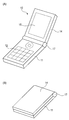
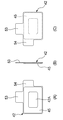
- (A) is a perspective view showing a developed state of the foldable portable terminal of the first embodiment according to the present invention
- (B) is a perspective view showing a folded state of the foldable portable terminal of the first embodiment
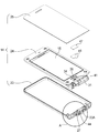
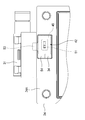
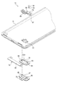
- the disassembled perspective view which shows the state which looked at the upper case of 1st Embodiment from the display part side
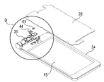
- the disassembled perspective view which shows the state which looked at the upper case of 1st Embodiment from the front cover side.
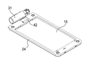
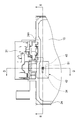
- the disassembled perspective view which shows the state which looked at the back cover which comprises the upper case of 1st Embodiment from the board
- FIG. 9 (A) is a front view showing the plate-like member and the waterproof member of the first embodiment, (B) is a side view thereof, and (C) is a rear view thereof.
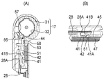
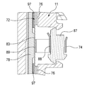
- the back view which shows the plate-shaped member and accommodating recess of 1st Embodiment (A) is a cross-sectional view taken along the line DD in FIG. 4,
- (B) is a cross-sectional view taken along the line EE in FIG.
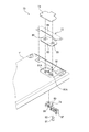
- the disassembled perspective view which shows the state which looked at the lower housing
- the disassembled perspective view which shows the state which looked at the lower housing
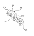
- the perspective view which shows the connection part and support member of 2nd Embodiment
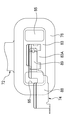
- the top view which shows the connection part and antenna of 2nd Embodiment
- the perspective view showing the covering member and the 1st waterproofing member of a 2nd embodiment
- the foldable portable terminal 10 has a lower housing (second housing) 11 provided with an operation unit 12 and an upper housing provided with a display unit 15 (second 1) and a non-waterproof connecting part 17 for foldably connecting the lower case 11 and the upper case 14.
- the lower housing 11 has a lower printed circuit board (printed circuit board) 21 (see FIG. 22) disposed therein, and is waterproof.
- the upper housing 14 is provided with a substantially rectangular front cover 23 formed in a bowl shape, a back cover 24 fitted on the opening side of the front cover 23, and a decorative panel 25 covering the back cover 24, and is waterproof. Is equipped.
- the front cover 23 is provided with an attachment portion 27 provided with a second connection portion 44 described later at the hinge portion side end portion 23A in the longitudinal direction of the upper housing 14.
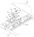
- the back cover 24 is formed in a substantially rectangular shape, and includes the display unit 15 and the upper printed circuit board (printed circuit board) 28 (see FIG. 4).
- the back cover 24 is provided with the non-waterproof hinge case 31 at the hinge portion side end 24A in the longitudinal direction of the upper housing 14, and the accommodation recess 34 provided at the hinge portion side end 24A.
- a projecting opening 35 is provided at the center, and an insertion hole 37 is provided in the wall portion 34A of the housing recess 34.
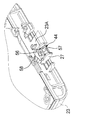
- a conductive hinge portion 32 (see FIG. 14A) is provided in the hinge case 31 . As shown in FIG. 14A, the hinge portion 32 and the hinge case 31 constitute a connecting portion 17.
- the foldable portable terminal 10 is a plate-like member having a first connection portion 41 provided at the hinge portion side end portion 23A in the longitudinal direction of the upper housing 14 and a conductive member connected to the first connection portion 41. 42, a second connection portion 44 connected to the plate member 42 and the hinge portion 32, a waterproof member 45 for waterproofing the upper case 14 from the hinge case 31, and a receiving member 47 for receiving the plate member 42 , And a housing dipole antenna operating as an antenna.
- the first connection portion 41 is a leaf spring which is formed so as to be elastically deformable in a substantially U-shape and in which the protrusion 51 is formed at the lower end portion 41A.
- the connection portion 41 By making the first connection portion 41 a plate spring, the connection portion can be obtained with a simple configuration.
- An upper end 41 B of the first connection portion 41 is connected (mounted) to the conductive portion 28 A of the upper printed board 28, and the protrusion 51 is elastically connected to the plate-like member 42.
- the plate-like member 42 is a metal plate formed in a substantially rectangular shape as shown in FIGS. 10 to 12 and provided with the first and second protrusions 53 and 54. By making the plate-like member 42 a metal plate, the conductivity of the plate-like member 42 can be easily obtained.
- the plate-like member 42 is disposed in the housing recess 34, and the first protrusion (a part of the plate-like member 42 (that is, a protrusion)) 53 is inserted into the insertion hole 37.
- the plate-like member 42 By arranging the plate-like member 42 in the housing recess 34, the plate-like member 42 is disposed between the display unit 15 and the hinge unit 32 (see FIG. 14A). Since the plate-like member 24 is disposed between the display unit 15 and the hinge unit 32 and the first projection 53 is made to project to the hinge unit 32, the antenna path length of the housing dipole antenna is secured. The length in the longitudinal direction of the upper housing 14 can be shortened, whereby the foldable portable terminal 10 can be miniaturized.
- first protrusion 53 that is, a part of the plate-like member 42
- first protrusion 53 is disposed (inserted) in the hinge case 31 by the first protrusion 53 being inserted into the insertion hole 37.
- the second projecting portion 54 is provided to facilitate the work of incorporating the plate-like member 42 into the housing recess 34.
- the second connection portion 44 is a plate spring provided at the attachment portion 27 of the front cover 23 as shown in FIG.
- the connection portion can be obtained with a simple configuration.
- the second connection portion 44 protrudes from the locking portion 56 that can be locked to the attachment portion 27 and from the locking portion 56 and can be elastically deformed toward the hinge portion 32.
- a second contact portion 58 which protrudes from the locking portion 56 and is bent toward the plate member 42 so as to be elastically deformable.
- the first contact portion 57 is a portion elastically connected to the hinge portion 32.
- the second contact portion 58 is a portion elastically connected to the first protrusion 53 in the hinge case 31.
- the waterproof member 45 is a double-sided adhesive tape closely attached to the plate-like member 42 and waterproofed from the hinge case 31 to the upper case 14 as shown in FIGS. 10 and 11.
- the waterproof member 45 is formed in a substantially rectangular frame shape, and is adhered to a portion 42A of the plate member 42 surrounding at least a contact point with the first connection portion 41.
- the receiving member 47 is formed in a substantially rectangular shape as shown in FIG. 2, FIG. 3 and FIG. 14 (B), receives the plate-like member 42, and has cushioning (elasticity) for suitably pressing the plate-like member 42. ).
- the housing dipole antenna includes the conductive portion 28A of the upper printed circuit board 28 provided on the upper housing 14, the plate-like member 42, the hinge portion 32, and the conductive surface of the lower printed circuit board 21 disposed inside the lower housing 11. And 21 A (see FIG. 22).
- the waterproof member 45 is brought into close contact with the plate-like member 42 to waterproof the hinge case 31 to the upper housing 14. As a result, even when the housing dipole antenna is configured, reliable waterproofness can be obtained.
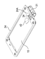
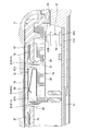
- the foldable portable terminal 70 includes a planar antenna 72 disposed outside the lower housing 11 and a conductive portion 21A of the lower printed circuit board 21 (FIG. 22). And the connection portion 74 elastically connected to the antenna 72, a first waterproofing member (waterproof member) 76 for waterproofing around the connection portion 74A of the antenna 72 and the connection portion 74, and a cover covering the antenna 72. And a member 78.
- a foldable portable terminal is illustrated, the structure of 2nd Embodiment is applicable also to a straight type portable terminal, for example.
- the lower housing 11 is provided with a communication hole 81 which exposes the antenna contact portion 89 of the connection portion 74 to the outside of the lower housing 11.
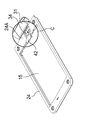
- the antenna 72 includes a base 83 formed in a substantially rectangular shape, and an antenna main body 84 extended in a strip shape from the base 83. A pair of through holes 85 are formed in the base 83 at predetermined intervals. The antenna 72 is attached to the lower housing 11 as shown in FIG.
- the connecting portion 74 is a member formed by bending a plate spring as shown in FIG.
- the connection portion 74 is a main body portion 88 attached to a support member 87 made of resin, and an antenna which is protruded from the main body portion 88 and bent elastically toward the base 83 (see FIG. 16) of the antenna 72. And a contact portion 89.
- the connecting portion 74 is connected to the conductive portion 21A of the lower printed circuit board 21 housed in the lower housing 11 via the pin connector 91 (see also FIG. 20).
- the antenna contact portion 89 is resiliently connected to the base 83 of the antenna 72 while being resiliently connected.
- the base end 92A of the main body 92 is mounted on the conductive portion 21A of the lower printed circuit board 21, and the projecting portion 93 is a coil spring (not shown) It is provided freely by The pin connector 91 is connected in a state where the projecting portion 93 is pressed by the main body 88 of the connecting portion 74.
- the first waterproofing member 76 is formed in a substantially rectangular frame shape and is in close contact with the periphery of the base 83 of the antenna 72, and the base 83 and the antenna contact portion 89 of the connecting portion 74. It is a double-sided adhesive tape which encloses and waterproofs the connection point 83A of the above.
- the covering member 78 is provided with a pair of engaging claws 95 that can be engaged with the opening edge 81A (see also FIG. 22) of the communication hole 81.
- the covering member 78 is formed in a substantially rectangular shape so as to cover a connection portion 83A of the antenna 72 with the connection portion 74, and a pair of engaging claws 95 is provided in the vicinity of both opposing sides.
- the pair of engagement claws 95 is a member that can be engaged with the opening edge 81A of the communication hole 81, as shown in FIG.
- a part of the support member 87 that supports the connection portion 74, specifically, a pair of projections 87A is disposed adjacent to the back surface of the pair of engagement claws 95. Therefore, it is possible to maintain the engaged state of the pair of engagement claws 95 with the opening edge 81A by the pair of projections 87A. By maintaining the engaged state of the pair of engagement claws 95 with the opening edge 81A of the communication hole 81, it is possible to prevent the covering member from coming off and maintain waterproofness.
- the covering member 78 is provided with a second waterproof member 97.
- the second waterproof member 97 is formed in a substantially rectangular frame shape, and is closely attached along the periphery of the covering member 78, and the connection between the base 83 and the antenna contact portion 89 of the connection portion 74. It is a double-sided adhesive tape that is waterproofed around the portion 83A.
- the first waterproof member 76 and the first waterproof member 97 are in close contact with the antenna 72, and the first waterproof member 76 and the first waterproof member 97 are used. , And can be waterproofed by surrounding the connection portion 83A between the antenna 72 and the connection portion 74. As a result, reliable waterproofness of the connection portion 83A between the antenna 72 and the connection portion 74 can be obtained.
- first and second embodiments an example in which a double-sided adhesive tape is used as the waterproof member 45, the first waterproof member 76, and the second waterproof member 97 has been described, but the invention is not limited thereto. It is also possible to use other waterproofing members such as crimps, adhesives and the like.
- the conductive portion 28A of the upper print substrate 28 and the conductive portion 21A of the lower print substrate 21 are used as component members of the antenna, but the invention is not limited thereto.
- another conductive member such as a metal frame of the upper housing 14 may be used as a component of the antenna.
- the present invention is suitable for application to a foldable portable terminal device and a portable terminal in which a first casing provided with a display unit and a second casing provided with an operation unit are foldably connected by a coupling unit.
Landscapes
- Engineering & Computer Science (AREA)
- Signal Processing (AREA)
- Computer Networks & Wireless Communication (AREA)
- Telephone Set Structure (AREA)
Priority Applications (2)
| Application Number | Priority Date | Filing Date | Title |
|---|---|---|---|
| US12/999,549 US20110128194A1 (en) | 2008-06-20 | 2009-02-02 | Foldable portable terminal and portable terminal |
| CN2009801282445A CN102100054A (zh) | 2008-06-20 | 2009-02-02 | 可折叠便携式终端和便携式终端 |
Applications Claiming Priority (2)
| Application Number | Priority Date | Filing Date | Title |
|---|---|---|---|
| JP2008162274A JP4463312B2 (ja) | 2008-06-20 | 2008-06-20 | 折り畳み式携帯端末および携帯端末 |
| JP2008-162274 | 2008-06-20 |
Publications (1)
| Publication Number | Publication Date |
|---|---|
| WO2009153899A1 true WO2009153899A1 (ja) | 2009-12-23 |
Family
ID=41433826
Family Applications (1)
| Application Number | Title | Priority Date | Filing Date |
|---|---|---|---|
| PCT/JP2009/000391 Ceased WO2009153899A1 (ja) | 2008-06-20 | 2009-02-02 | 折り畳み式携帯端末および携帯端末 |
Country Status (4)
| Country | Link |
|---|---|
| US (1) | US20110128194A1 (enExample) |
| JP (1) | JP4463312B2 (enExample) |
| CN (1) | CN102100054A (enExample) |
| WO (1) | WO2009153899A1 (enExample) |
Families Citing this family (8)
| Publication number | Priority date | Publication date | Assignee | Title |
|---|---|---|---|---|
| JP4990958B2 (ja) * | 2009-11-30 | 2012-08-01 | パナソニック株式会社 | 折り畳み式携帯端末および携帯端末 |
| KR101281895B1 (ko) * | 2011-08-24 | 2013-07-03 | 주식회사 팬택 | Fpc 방수 구조체 |
| JP5873756B2 (ja) * | 2012-05-15 | 2016-03-01 | 京セラ株式会社 | 携帯電子機器 |
| JP5871757B2 (ja) * | 2012-09-13 | 2016-03-01 | シャープ株式会社 | 携帯端末 |
| JP5937147B2 (ja) * | 2014-06-26 | 2016-06-22 | 原田工業株式会社 | アンテナユニット |
| TW201630510A (zh) * | 2015-02-09 | 2016-08-16 | 鴻海精密工業股份有限公司 | 保護套 |
| ES2700853T3 (es) * | 2015-12-01 | 2019-02-19 | Friwo Geraetebau Gmbh | Cubierta impermeable, suministro de energía y método de montaje |
| CN116937209B (zh) * | 2023-07-11 | 2024-09-13 | 荣耀终端有限公司 | 一种电子设备 |
Citations (8)
| Publication number | Priority date | Publication date | Assignee | Title |
|---|---|---|---|---|
| JPS62277803A (ja) * | 1986-05-26 | 1987-12-02 | Nippon Telegr & Teleph Corp <Ntt> | 携帯無線機 |
| JPH07273522A (ja) * | 1994-03-31 | 1995-10-20 | Matsushita Electric Ind Co Ltd | アンテナ取付け装置 |
| JPH09232841A (ja) * | 1996-02-28 | 1997-09-05 | Matsushita Electric Ind Co Ltd | アンテナの配置方法 |
| JP3017148B2 (ja) * | 1997-11-10 | 2000-03-06 | 埼玉日本電気株式会社 | アンテナ保持装置、およびアンテナ保持方法 |
| JP2004179110A (ja) * | 2002-11-29 | 2004-06-24 | Kyocera Corp | コネクタ接続部構造及びこれを用いた携帯端末装置 |
| JP2005091082A (ja) * | 2003-09-16 | 2005-04-07 | Denso Corp | アンテナ一体型ナビゲーション装置 |
| JP2005348341A (ja) * | 2004-06-07 | 2005-12-15 | Casio Comput Co Ltd | 携帯用電子機器 |
| JP3791510B2 (ja) * | 2002-05-13 | 2006-06-28 | 日本電気株式会社 | 防水構造を備える折り畳み型携帯端末装置 |
Family Cites Families (6)
| Publication number | Priority date | Publication date | Assignee | Title |
|---|---|---|---|---|
| US7251512B2 (en) * | 2002-05-13 | 2007-07-31 | Nec Corporation | Water-proof collapsible cellular terminal apparatus |
| KR100539935B1 (ko) * | 2003-08-08 | 2005-12-28 | 삼성전자주식회사 | 휴대 단말기의 그라운드 연결장치 |
| JP4364699B2 (ja) * | 2004-03-30 | 2009-11-18 | 富士通株式会社 | 折畳み式電子装置 |
| JP4300210B2 (ja) * | 2004-11-18 | 2009-07-22 | 株式会社カシオ日立モバイルコミュニケーションズ | 携帯型無線機 |
| JP4227146B2 (ja) * | 2005-07-21 | 2009-02-18 | 株式会社カシオ日立モバイルコミュニケーションズ | 折畳み式携帯無線通信機 |
| US8005517B2 (en) * | 2006-10-25 | 2011-08-23 | Lg Electronics Inc. | Mobile communication device |
-
2008
- 2008-06-20 JP JP2008162274A patent/JP4463312B2/ja not_active Expired - Fee Related
-
2009
- 2009-02-02 US US12/999,549 patent/US20110128194A1/en not_active Abandoned
- 2009-02-02 CN CN2009801282445A patent/CN102100054A/zh active Pending
- 2009-02-02 WO PCT/JP2009/000391 patent/WO2009153899A1/ja not_active Ceased
Patent Citations (8)
| Publication number | Priority date | Publication date | Assignee | Title |
|---|---|---|---|---|
| JPS62277803A (ja) * | 1986-05-26 | 1987-12-02 | Nippon Telegr & Teleph Corp <Ntt> | 携帯無線機 |
| JPH07273522A (ja) * | 1994-03-31 | 1995-10-20 | Matsushita Electric Ind Co Ltd | アンテナ取付け装置 |
| JPH09232841A (ja) * | 1996-02-28 | 1997-09-05 | Matsushita Electric Ind Co Ltd | アンテナの配置方法 |
| JP3017148B2 (ja) * | 1997-11-10 | 2000-03-06 | 埼玉日本電気株式会社 | アンテナ保持装置、およびアンテナ保持方法 |
| JP3791510B2 (ja) * | 2002-05-13 | 2006-06-28 | 日本電気株式会社 | 防水構造を備える折り畳み型携帯端末装置 |
| JP2004179110A (ja) * | 2002-11-29 | 2004-06-24 | Kyocera Corp | コネクタ接続部構造及びこれを用いた携帯端末装置 |
| JP2005091082A (ja) * | 2003-09-16 | 2005-04-07 | Denso Corp | アンテナ一体型ナビゲーション装置 |
| JP2005348341A (ja) * | 2004-06-07 | 2005-12-15 | Casio Comput Co Ltd | 携帯用電子機器 |
Also Published As
| Publication number | Publication date |
|---|---|
| CN102100054A (zh) | 2011-06-15 |
| US20110128194A1 (en) | 2011-06-02 |
| JP2010004392A (ja) | 2010-01-07 |
| JP4463312B2 (ja) | 2010-05-19 |
Similar Documents
| Publication | Publication Date | Title |
|---|---|---|
| WO2009153899A1 (ja) | 折り畳み式携帯端末および携帯端末 | |
| JP4762126B2 (ja) | 電子機器 | |
| US9450294B2 (en) | Antenna apparatus for portable terminal | |
| US6879849B2 (en) | In-built antenna for mobile communication device | |
| JP5514262B2 (ja) | アンテナ給電装置 | |
| JP4364271B2 (ja) | 電子機器 | |
| JP2010004392A5 (enExample) | ||
| CN103000984A (zh) | 车载用电子设备 | |
| JP4249192B2 (ja) | モジュール機器用電気機器 | |
| JP2007074226A (ja) | 車載用アンテナ装置 | |
| JP5165602B2 (ja) | アンテナ保持構造およびアンテナ装置 | |
| JP4990958B2 (ja) | 折り畳み式携帯端末および携帯端末 | |
| JP3098997U (ja) | アンテナ用アンプ | |
| JP2013098128A (ja) | フラット回路体のコネクタ接続構造 | |
| KR100701868B1 (ko) | 이동 통신 단말기용 내장 안테나 | |
| JP4870002B2 (ja) | アンテナ装置 | |
| JP4367665B2 (ja) | 車載用アンテナ装置 | |
| KR20060065323A (ko) | 내장형 안테나를 구비한 이동통신 단말기 | |
| JP4594368B2 (ja) | 携帯無線装置 | |
| JP4461881B2 (ja) | 通信端末装置及びその組立方法 | |
| JP2014110617A (ja) | 通信端末装置、アンテナ装置および電子機器 | |
| JP2007335281A (ja) | 電子部品取付用ソケット | |
| JP2010119002A (ja) | 携帯端末装置 | |
| JP7324597B2 (ja) | 携帯端末 | |
| JP4692767B2 (ja) | カードホルダ基板取付構造 |
Legal Events
| Date | Code | Title | Description |
|---|---|---|---|
| WWE | Wipo information: entry into national phase |
Ref document number: 200980128244.5 Country of ref document: CN |
|
| 121 | Ep: the epo has been informed by wipo that ep was designated in this application |
Ref document number: 09766347 Country of ref document: EP Kind code of ref document: A1 |
|
| WWE | Wipo information: entry into national phase |
Ref document number: 12999549 Country of ref document: US |
|
| NENP | Non-entry into the national phase |
Ref country code: DE |
|
| 122 | Ep: pct application non-entry in european phase |
Ref document number: 09766347 Country of ref document: EP Kind code of ref document: A1 |