WO2009142172A1 - 二つ割り外輪、これを用いた二つ割り転がり軸受、転がり軸受の取付構造及び取付方法 - Google Patents
二つ割り外輪、これを用いた二つ割り転がり軸受、転がり軸受の取付構造及び取付方法 Download PDFInfo
- Publication number
- WO2009142172A1 WO2009142172A1 PCT/JP2009/059129 JP2009059129W WO2009142172A1 WO 2009142172 A1 WO2009142172 A1 WO 2009142172A1 JP 2009059129 W JP2009059129 W JP 2009059129W WO 2009142172 A1 WO2009142172 A1 WO 2009142172A1
- Authority
- WO
- WIPO (PCT)
- Prior art keywords
- split
- outer ring
- rolling bearing
- circumferential direction
- bearing
- Prior art date
Links
- 238000005096 rolling process Methods 0.000 title claims abstract description 87
- 238000000034 method Methods 0.000 title claims description 9
- 230000002093 peripheral effect Effects 0.000 claims description 45
- 230000013011 mating Effects 0.000 description 23
- 238000005336 cracking Methods 0.000 description 4
- 230000011218 segmentation Effects 0.000 description 4
- 238000002485 combustion reaction Methods 0.000 description 3
- 230000007423 decrease Effects 0.000 description 3
- 230000004048 modification Effects 0.000 description 3
- 238000012986 modification Methods 0.000 description 3
- 230000015572 biosynthetic process Effects 0.000 description 2
- 230000003247 decreasing effect Effects 0.000 description 2
- 230000006866 deterioration Effects 0.000 description 2
- 238000006073 displacement reaction Methods 0.000 description 2
- 238000003825 pressing Methods 0.000 description 2
- 229910000831 Steel Inorganic materials 0.000 description 1
- 230000004323 axial length Effects 0.000 description 1
- 238000005520 cutting process Methods 0.000 description 1
- 238000010586 diagram Methods 0.000 description 1
- 239000000446 fuel Substances 0.000 description 1
- 238000010438 heat treatment Methods 0.000 description 1
- 238000004519 manufacturing process Methods 0.000 description 1
- 239000010959 steel Substances 0.000 description 1
Images


Classifications
-
- F—MECHANICAL ENGINEERING; LIGHTING; HEATING; WEAPONS; BLASTING
- F16—ENGINEERING ELEMENTS AND UNITS; GENERAL MEASURES FOR PRODUCING AND MAINTAINING EFFECTIVE FUNCTIONING OF MACHINES OR INSTALLATIONS; THERMAL INSULATION IN GENERAL
- F16C—SHAFTS; FLEXIBLE SHAFTS; ELEMENTS OR CRANKSHAFT MECHANISMS; ROTARY BODIES OTHER THAN GEARING ELEMENTS; BEARINGS
- F16C9/00—Bearings for crankshafts or connecting-rods; Attachment of connecting-rods
- F16C9/02—Crankshaft bearings
-
- F—MECHANICAL ENGINEERING; LIGHTING; HEATING; WEAPONS; BLASTING
- F16—ENGINEERING ELEMENTS AND UNITS; GENERAL MEASURES FOR PRODUCING AND MAINTAINING EFFECTIVE FUNCTIONING OF MACHINES OR INSTALLATIONS; THERMAL INSULATION IN GENERAL
- F16C—SHAFTS; FLEXIBLE SHAFTS; ELEMENTS OR CRANKSHAFT MECHANISMS; ROTARY BODIES OTHER THAN GEARING ELEMENTS; BEARINGS
- F16C19/00—Bearings with rolling contact, for exclusively rotary movement
- F16C19/22—Bearings with rolling contact, for exclusively rotary movement with bearing rollers essentially of the same size in one or more circular rows, e.g. needle bearings
- F16C19/44—Needle bearings
- F16C19/46—Needle bearings with one row or needles
- F16C19/466—Needle bearings with one row or needles comprising needle rollers and an outer ring, i.e. subunit without inner ring
-
- F—MECHANICAL ENGINEERING; LIGHTING; HEATING; WEAPONS; BLASTING
- F16—ENGINEERING ELEMENTS AND UNITS; GENERAL MEASURES FOR PRODUCING AND MAINTAINING EFFECTIVE FUNCTIONING OF MACHINES OR INSTALLATIONS; THERMAL INSULATION IN GENERAL
- F16C—SHAFTS; FLEXIBLE SHAFTS; ELEMENTS OR CRANKSHAFT MECHANISMS; ROTARY BODIES OTHER THAN GEARING ELEMENTS; BEARINGS
- F16C33/00—Parts of bearings; Special methods for making bearings or parts thereof
- F16C33/30—Parts of ball or roller bearings
- F16C33/58—Raceways; Race rings
- F16C33/60—Raceways; Race rings divided or split, e.g. comprising two juxtaposed rings
-
- F—MECHANICAL ENGINEERING; LIGHTING; HEATING; WEAPONS; BLASTING
- F16—ENGINEERING ELEMENTS AND UNITS; GENERAL MEASURES FOR PRODUCING AND MAINTAINING EFFECTIVE FUNCTIONING OF MACHINES OR INSTALLATIONS; THERMAL INSULATION IN GENERAL
- F16C—SHAFTS; FLEXIBLE SHAFTS; ELEMENTS OR CRANKSHAFT MECHANISMS; ROTARY BODIES OTHER THAN GEARING ELEMENTS; BEARINGS
- F16C9/00—Bearings for crankshafts or connecting-rods; Attachment of connecting-rods
- F16C9/04—Connecting-rod bearings; Attachments thereof
-
- F—MECHANICAL ENGINEERING; LIGHTING; HEATING; WEAPONS; BLASTING
- F16—ENGINEERING ELEMENTS AND UNITS; GENERAL MEASURES FOR PRODUCING AND MAINTAINING EFFECTIVE FUNCTIONING OF MACHINES OR INSTALLATIONS; THERMAL INSULATION IN GENERAL
- F16C—SHAFTS; FLEXIBLE SHAFTS; ELEMENTS OR CRANKSHAFT MECHANISMS; ROTARY BODIES OTHER THAN GEARING ELEMENTS; BEARINGS
- F16C2240/00—Specified values or numerical ranges of parameters; Relations between them
- F16C2240/40—Linear dimensions, e.g. length, radius, thickness, gap
- F16C2240/46—Gap sizes or clearances
Definitions
- the present invention relates to, for example, a split rolling bearing interposed between a crankpin and a connecting rod large end in an internal combustion engine, a split outer ring used therefor, and a mounting structure and mounting method of such a rolling bearing.
- the bearing that supports the crankshaft that converts the reciprocating motion of the pistons into rotational motion is arranged between the counterweights or between the counterweight and the connecting rod large end, A split bearing divided into two is used.
- Patent Document 2 shows an example in which a split bearing is interposed between a crankpin of an internal combustion engine and a connecting rod large end.
- This split bearing has a split outer ring that is inscribed in the inner peripheral surface of the connecting rod large end, and a plurality of rollers that are rotatably arranged between the inner peripheral surface of the split outer ring and the outer peripheral surface of the crank pin. is doing.
- the split outer ring is configured to be split by combining a pair of split outer ring members formed in a substantially semi-cylindrical shape.
- the split bearing can be split in the radial direction by using a split outer ring that can be split, and can be incorporated on the outer peripheral side of the crankpin that is offset with respect to the rotating shaft of the crankshaft.
- the pair of split outer ring members abut against each other in the circumferential direction, they may move relative to each other in the axial direction and may be displaced. For this reason, among the circumferential end portions that face each other, one end portion is formed with a mountain-shaped convex portion protruding in the circumferential direction, and the other end portion is provided with the convex portion. V-shaped concave portions corresponding to the above are formed, and by engaging the convex portions and the concave portions, the pair of split outer ring members are prevented from moving relative to each other in the axial direction.
- each pair of split outer rings are in contact with each other to form a mating surface, but an assembly error in a housing having a support hole for accommodating the rolling bearing
- radial displacement may occur at both ends of the facing outer ring on the mating surface.
- a step that protrudes inward in the radial direction may be formed on the mating surface.
- JP 2007-247818 A Japanese Patent Laid-Open No. 2005-90696 JP 2006-125606 A
- the concave portion at the end of the divided outer ring member is formed by cutting out into a V shape, and therefore stress concentration tends to occur at the bottom.
- the split outer ring is mounted in a press-fit state on the inner peripheral surface of the connecting rod large end, a stress in the direction of reducing the diameter acts on the entire split outer ring.
- the top of the triangular convex portion fitted in the concave portion presses the bottom of the concave portion.
- stress concentration occurs at the bottom of the concave portion, and cracks along the circumferential direction are generated in the split outer ring member starting from this bottom, which is a factor of reducing durability as a split outer ring.
- the “flank” is configured by an inclined surface linearly decreasing or increasing in diameter linearly, but instead of the outer ring raceway surface and an arcuate curved surface having a reverse curvature. Can be formed on the inner diameter side edge of the mating surface.
- the present invention has been made in view of such circumstances, and prevents cracks from occurring in the split outer ring member, suppresses deterioration in durability, and causes noise and vibration associated with passage of rolling elements to the mating surface. It is an object of the present invention to provide a split outer ring that can significantly suppress the occurrence of the occurrence of the problem, and a split roller bearing using the same.
- One aspect of the present invention for achieving the above object is a split outer ring used for a split bearing that can be divided in the radial direction, and is formed in a semi-cylindrical shape, and both end portions in the circumferential direction are butted against each other.
- a pair of split outer ring members having a cylindrical shape are formed, and one end portion of the circumferential end portions that are abutted with each other extends parallel to the axis from the both axial end edges toward the center.
- a pair of first plane portions and a V-shaped recess that is recessed in the circumferential direction with respect to the first plane portion between the pair of first plane portions are formed at the end portions.
- a gap is formed between the concave portion and the convex portion to avoid contact between the bottom portion of the concave portion and the top portion of the convex portion. Even when stress is applied in the direction of diameter reduction to the entire split outer ring when used in a split bearing, the top of the convex portion directly contacts the bottom of the concave portion and presses the bottom of the concave portion. Can be prevented. Furthermore, since the stress can be borne by the first and second plane portions that are in contact with each other, it is possible to prevent the stress from being excessively concentrated on the bottom of the recess.
- the gap is preferably formed by making the top part of the convex part a curved surface.
- the concave part and the convex part are formed by a simple method such as providing a curved surface on the top part of the convex part.
- a gap can be provided between the two.
- the gap can be formed by a thin portion provided at the bottom of the concave portion, and in this case as well, the gap can be provided between the concave portion and the convex portion by a simple method as described above. .
- the said clearance gap may be formed by making the vertex angle of the said convex part larger than the internal angle of the said recessed part.
- a gap can be provided not only between the bottom of the concave portion and the top of the convex portion but also almost the entire region between the concave portion and the convex portion, so that excessive stress concentration in the concave portion is more effective. Can be prevented.
- the curved surface part may be formed in each inner peripheral side of the edge part of both division
- These curved surface portions constitute relief grooves that are recessed radially outward with respect to the track surface when both ends are butted against each other to form a split outer ring, and are provided over the entire axial direction of the track surface. Is preferred.
- the cross-sectional shape of the relief groove is a concave curved surface of a predetermined R dimension (curvature radius) whose center is located on a radial line passing through the boundary between both ends, and is positioned in a predetermined circumferential range L. Is set.
- the range L is set so that the inner peripheral side of the concave portion and the convex portion becomes a part of the escape groove.
- the clearance groove is provided over the entire boundary between both ends including the boundary between the concave portion and the convex portion, whereby the raceway surface and the crank pin that act on the cylindrical roller rolling through the clearance groove.
- the contact surface pressure from the outer peripheral surface can be reduced. As a result, it is possible to effectively prevent the occurrence of vibration or the like that occurs when the cylindrical roller passes the boundary between both ends.
- the outer ring is formed in a semi-cylindrical shape, and includes a split outer ring formed of a pair of split outer ring members that are cylindrically formed by abutting both circumferential ends.
- a split split two-way bearing in the radial direction having a plurality of rolling elements arranged on the surface side and a cage for holding the rolling elements so as to be arranged at substantially equal intervals in the circumferential direction, the split outer ring Is the aforementioned split outer ring.
- the split outer ring member can be prevented from cracking by using the above-described split outer ring. As a result, it is possible to prevent a decrease in durability as a split roller bearing.
- the split roller bearing according to another aspect of the present invention is formed in a semi-cylindrical shape, and a split outer ring formed of a pair of split outer ring members that are formed into a cylindrical shape by abutting the circumferential ends of each other,
- a two-rolling bearing comprising a plurality of rolling elements arranged on the inner peripheral surface side of the outer ring and a cage for holding the rolling elements so as to be arranged at substantially equal intervals in the circumferential direction, and in which a shaft is fitted.
- On the flank formed at the inner diameter side edge of the circumferential end surface of the split outer ring at least the cross-sectional shape in the range where the rolling elements come into contact is constituted by a relaxation curve.
- the relaxation curve can be a clothoid curve or a cubic parabola.
- the speed vector of the rolling elements in the vicinity of the junction can be gradually changed, and the generation of vibration and noise due to a sudden change in the speed vector of the rolling elements can be suppressed.
- a bearing structure including the above-described split rolling bearing and a housing having a support hole that closely supports the split split bearing.
- the speed vector of the rolling elements in the vicinity of the joint can be gradually changed, and noise and noise caused by the rolling elements passing through the mating surface Generation of vibration can be greatly suppressed.
- Another aspect of the present invention is a mounting structure for a rolling bearing with respect to a shaft portion of a crankshaft,
- the rolling bearing is the above-described split rolling bearing, further comprising a pair of split inner rings attached to the outer peripheral surface of the shaft portion and split in two in the circumferential direction.
- the axial pressure is held in the axial direction by the crank arms arranged on both axial sides of the shaft portion.
- the journal portion of the crankshaft usually does not have the performance such as wear resistance required for the inner ring of the rolling bearing, and there is a problem that peeling or wear occurs at an early stage. For this reason, it is conceivable to separately attach an inner ring to the journal part, but since there are crank arms on both sides in the axial direction of the journal part, the inner ring needs to be divided into two parts in the same manner as the outer ring. It is required that the inner ring be firmly attached to the journal portion so as not to occur. However, if the inner ring has a split structure, it cannot be strongly pressed against the journal part, so it is difficult to attach it firmly to the journal part.
- the split inner ring is clamped and held in the axial direction by the crank arms arranged on both axial sides of the shaft part, so that the split inner ring can be firmly attached to the shaft part.
- the occurrence of creep of the split inner ring with respect to the shaft portion can be suppressed.
- the circumferential direction in which the circumferential end of one split inner ring and the circumferential end of the other split inner ring are axially pressed against each other by the clamping force of the two split inner rings by the crank arm It is preferable that a surface extending along is formed. In this case, since the two split inner rings are pressed against each other in the axial direction on the surface extending along the circumferential direction, the relative positions of the two split inner rings are firmly fixed. Therefore, even if the inner ring has a split structure, the split inner ring can be more firmly attached to the shaft portion of the crankshaft.
- a method of attaching the above-described rolling bearing to a shaft portion of a crankshaft, the axial dimension of the two split inner rings, and the crank arm disposed on both sides in the axial direction of the shaft portion is provided.
- An axial interference margin is set between the axial interval, and the two split inner rings are inserted between the crank arms by a cold fit of the two split inner rings or a shrink fit of the shaft part. Install.
- the split inner ring can be firmly attached to the shaft portion of the crankshaft.
- the split outer ring and the split rolling bearing of the present invention it is possible to greatly suppress the generation of noise and vibration associated with the rolling element passing through the mating surface, and to prevent the split outer ring member from cracking and to improve durability. It is possible to suppress the deterioration of the property.
- FIG. 3 is an enlarged view of a main part of a split outer ring, in which (a) is a front view of a portion where both end portions of a split outer ring member are butted, and (b) is a line bb in FIG. 3 (a). It is arrow sectional drawing. It is a principal part enlarged view of the split bearing which concerns on 2nd embodiment of this invention, and has shown the part which faced the both ends of both division
- FIG. 2 is an enlarged explanatory view in the vicinity of a mating surface of the rolling bearing shown in FIG. 1. It is a figure explaining the inclination of the various escape parts with respect to an outer ring track. It is sectional explanatory drawing of the bearing structure of 4th embodiment of this invention. It is sectional explanatory drawing of the modification of the bearing structure of 4th embodiment of this invention.
- FIG. 1 is a side view showing the structure of a split bearing according to the first embodiment of the present invention.
- the split bearing 1 is interposed, for example, between the outer periphery of the crankpin P of the internal combustion engine and the inner periphery of the large end C1 of the connecting rod C so that the connecting rod C can swing with respect to the crankpin P. I support it.
- the split roller bearing 1 includes a split outer ring 2 inscribed in the inner peripheral surface C2 of the large end C1, and a space between the raceway surface 2a formed on the inner peripheral side of the split outer ring 2 and the outer peripheral surface P1 of the crank pin P.
- a plurality of cylindrical rollers 3 that are arranged so as to be freely rollable, and a split cage 4 for holding the cylindrical rollers 3 so as to be arranged at equal intervals in the circumferential direction.
- the split outer ring 2 and the split cage 4 can be divided in the radial direction, and the split bearing 1 can also be divided in the radial direction.
- the double split bearing 1 is interposed in the inner peripheral surface C2 in a press-fit state. For this reason, a stress in the direction of reducing the diameter acts on the split outer ring 2 when it is incorporated as the split roller bearing 1 into the large end C1 of the connecting rod C.
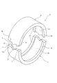
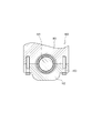
- FIG. 2 is a perspective view showing the split outer ring 2.
- the split outer ring 2 has a first divided outer ring member 5 and a second divided outer ring member 6 formed in a substantially semi-cylindrical shape, and each of the pair of divided outer ring members 5 and 6 has a circumferential direction.
- a cylindrical outer ring is formed by abutting the end portions 5a and 6a with each other.
- flanges 2b projecting in the radial direction with respect to the raceway surface 2a are formed along the circumferential direction.
- the flange 2b regulates the movement of the cylindrical rollers 3 that are a plurality of rolling elements disposed on the raceway surface 2a in the axial direction.
- the end portion 5a as one end portion of the first split outer ring member 5 has a pair of first plane portions 7 extending in parallel to the axis from both ends in the axial direction toward the center, and the pair of first planes.
- a V-shaped recess 8 that is recessed in the circumferential direction with respect to the first flat surface portion 7 is formed between the portions 7.
- the end portion 6a of the second split outer ring member 6 as the other end portion butted against the end portion 5a includes a pair of second plane portions 9 extending in parallel to the axis from both ends in the axial direction, and the pair.
- a convex portion 10 formed between the second flat surface portions 9 and protruding in the circumferential direction and introduced into the concave portion 8 of the first split outer ring member 5 is formed.
- the pair of first plane portions 7 and the pair of second plane portions 9 are in contact with each other with both end portions 5a and 6a butting each other.
- the convex part 10 is formed in the shape (mountain shape) corresponding to the recessed part 8 of the 1st division
- the first divided outer ring member 5 and the second divided outer ring member 6 are axially arranged. Prevents deviation.
- FIG. 3 is an enlarged view of a main part of the split outer ring 2, (a) is a front view of a portion where both end portions 5 a and 6 a are butted together, and (b) is a view in FIG. It is a sectional view taken along line bb.
- the two flat surface portions 7 and 9 of the two divided outer ring members 5 and 6 are in contact with each other as described above.
- the concave portion 8 of the first split outer ring member 5 is formed in a V shape by a pair of inclined wall surfaces 8a that are linearly inclined from the first flat surface portion 7 in a direction recessed in the circumferential direction.
- the portion where the inclined wall surfaces 8 a intersect with each other is the bottom 8 b of the recess 8.
- the convex portion 10 of the second split outer ring member 6 is formed in a mountain shape by a pair of inclined side surfaces 10a that are inclined linearly in a direction protruding in the circumferential direction from the second flat surface portion 9.
- a portion where the pair of inclined side surfaces 10 a intersect with each other is a top portion 10 b of the convex portion 10.
- the concave portion 8 and the convex portion 10 are provided substantially at the center in the axial direction and are formed so as to be symmetric with respect to the center in the axial direction.
- the apex angle ⁇ of the convex portion 10 that is an angle formed by the pair of inclined side surfaces 10a is larger than the inner angle ⁇ of the concave portion 8 that is an angle formed by the pair of inclined wall surfaces 8a. Is set. In this way, by setting the apex angle ⁇ and the inner angle ⁇ , a gap S is formed between the convex portion 10 and the concave portion 8 as shown in FIG. The gap S is formed over almost the entire area between the convex portion 10 and the concave portion 8 including the space between the bottom portion 8 b of the concave portion 8 and the top portion 10 b of the convex portion 10, and the top portion of the convex portion 10.
- the gap S gradually decreases as the base end portion of the convex portion 10 is approached, and the convex portion 10 and the concave portion 8 are in contact with each other in the vicinity of the base end portion of the convex portion 10. In the present embodiment, the vicinity of the base end portion of the convex portion 10 is in contact with the concave portion 8, thereby preventing the two divided outer ring members 5 and 6 from being displaced in the axial direction.
- the gap S is preferably set to about 60 ⁇ m at the maximum. This is because if it is set to be larger than that, it is difficult to effectively prevent the split outer ring members 5 and 6 from shifting in the axial direction.
- curved surfaces are formed on the inner peripheral sides of the end portions 5a and 6a of the split outer ring members 5 and 6 so as to taper toward the distal end edges in the circumferential direction of the end portions 5a and 6a.
- Portions 5b and 6b are formed.
- These curved surface portions 5b and 6b constitute a relief groove 2c that is recessed radially outward with respect to the locus of the raceway surface 2a when both end portions 5a and 6a are butted against each other to form the split outer ring 2.
- the escape groove 2c is provided over the entire axial direction of the raceway surface 2a.
- the cross-sectional shape of the relief groove 2c is a concave curved surface having a predetermined R dimension centered on a radial line passing through the boundary between both ends 5a and 6a, and is set to be positioned in a predetermined circumferential range L.
- the range L is set so that the inner peripheral side of the concave portion 8 and the convex portion 10 becomes a part of the escape groove 2c.
- the escape groove 2c is provided over the entire boundary between both end portions 5a and 6a including the boundary between the concave portion 8 and the convex portion 10, whereby the cylindrical roller 3 that rolls and passes through the escape groove 2c.
- the contact surface pressure from the raceway surface 2a and the outer peripheral surface P1 of the crank pin P can be lowered. As a result, it is possible to effectively prevent the occurrence of vibration or the like that occurs when the cylindrical roller 3 passes through the boundary between the both end portions 5a and 6a.
- the concave portion 8 is formed between the bottom portion 8b of the convex portion 10 and the top portion 10b of the convex portion 10 so as to avoid contact between the top portion 10b and the bottom portion 8b. It is possible to prevent the bottom portion 8b from being pressed directly against the bottom portion 8b. Furthermore, since the stress can be borne by the first and second flat portions 7 and 9 that are in contact with each other, it is possible to prevent the stress from being excessively concentrated on the bottom portion 8b of the recess 8.
- the top portion 10b of the convex portion 10 presses the bottom portion 8b of the concave portion 8 while preventing stress from being excessively concentrated on the bottom portion 8b of the concave portion 8.
- the first split outer ring member 5 it is possible to prevent the first split outer ring member 5 from being cracked along the circumferential direction starting from the bottom 8b.
- the convex part 10 is formed in the value whose apex angle (alpha) is larger than the internal angle (beta) of the recessed part 8, Therefore Between the bottom part 8b of the recessed part 8 and the top part 10b of the convex part 10 only. Instead, the gap S can be provided over almost the entire area between the concave portion 8 and the convex portion 10. Thereby, the excessive stress concentration to the recessed part 8 can be prevented more effectively.
- the split roller bearing 1 of the present embodiment can prevent the first split outer ring member 5 from cracking by using the split outer ring 2 described above. As a result, it is possible to prevent the durability of the split roller bearing 1 from being lowered.
- FIG. 4 is an enlarged view of a main part of the split roller bearing 1 according to the second embodiment of the present invention, and shows a portion where both end portions 5a and 6a of both split outer ring members 5 and 6 are abutted.
- the main difference between this embodiment and said 1st embodiment is that the clearance gap S is formed by making the top part 10b of the convex part 10 into a curved surface.
- the inner angle ⁇ of the concave portion 8 and the apex angle ⁇ of the convex portion 10 are set to substantially the same value, and the inclined wall surface 8a of the concave portion 8 and the inclined side surface 10a of the convex portion 10 are in contact with each other.
- the top portion 10 b of the convex portion 10 is curved as described above, and a gap S is formed between the bottom portion 8 b of the concave portion 8 and the top portion 10 b of the convex portion 10. Also in the case of the present embodiment, the gap S can prevent the top portion 10b of the convex portion 10 from directly contacting and pressing the bottom portion 8b of the concave portion 8.
- the clearance gap S can be provided between the bottom part 8b and the top part 10b by the simple method of making the top part 10b of the convex part 10 into a curved surface, and it is advantageous in terms of cost.
- FIG. 5 is an enlarged view of a main part of the split roller bearing 1 according to the third embodiment of the present invention, and shows a portion where both end portions 5a and 6a of both split outer ring members 5 and 6 are abutted.
- the difference between the present embodiment and each of the above embodiments is that the gap S is formed by the thin portion 11 provided on the bottom portion 8 b of the recess 8.
- the shading portion 11 is formed to be recessed from the inclined wall surface 8a of the concave portion 8 in the circumferential direction, and a gap S is formed with the top portion 10b of the convex portion 10.
- the inside portion 11 is formed with a smooth curved surface, and prevents stress from being concentrated on a part as much as possible.
- the gap S can be provided between the bottom portion 8b and the top portion 10b by a simple method such as forming the thinning portion 11 in the bottom portion 8b of the recess 8, and the cost is the same as in the second embodiment. Is advantageous.
- the present invention is not limited to the above embodiments.
- the pair of inclined wall surfaces 8a constituting the concave portion 8 and the pair of inclined side surfaces 10a constituting the convex portion 10 are each formed to be inclined linearly.
- the concave portion 8 and the convex portion 10 as a whole only have to be formed in a substantially V shape and a substantially mountain shape, respectively.
- Those formed by convexly curving the inclined side surface 10a and those concavely curved conversely include V shapes and mountain shapes.
- tilt angle of the inclination wall surface 8a and the inclination side surface 10a can also be changed in an intermediate part.
- FIG. 7 is an explanatory cross-sectional view of a rolling bearing 101 according to a fourth embodiment of the present invention
- FIG. 8 is an enlarged explanatory view of the vicinity of the mating surface of the rolling bearing 101 shown in FIG.
- the rolling bearing 101 is formed in a semi-cylindrical shape, and is divided into two in the circumferential direction, and two pairs of split outer rings (outer ring members) that are formed into a cylindrical shape by abutting both ends in the circumferential direction.
- the cage 104 is provided with a split portion at one place in the circumferential direction, and the cage 104 can be assembled by expanding the diameter of the split portion when assembled into the shaft 105. However, it is good also as a split type which provided the split part in two places of the circumferential direction.
- the shaft 105 is fitted into the rolling bearing 101 by being supported by the plurality of rollers 103.
- the shaft 105 also functions as an inner ring.
- a mating surface C is constituted by the circumferential end surface of the split outer ring member 102a and the circumferential end surface of the split outer ring member 102b facing the end surface.
- a curved surface B as a flank is formed on the inner diameter side edge of each end surface of the split outer ring member 102a, 102b constituting the mating surface C.
- the cross-sectional shape of the range where the roller 103 rolls and contacts is constituted by a relaxation curve. More specifically, as shown in FIG.
- the circumferential direction is a boundary between the raceway surfaces 102a1 and 102b1 of the split outer ring members 102a and 102b and the curved surface B from the mating surface C.
- the range L reaches the junction point J.
- the cross-sectional shape of the curved surface in the range h from the raceway surfaces 102a1 and 102b1 to the radially outward direction is constituted by a relaxation curve.
- the size of L can be appropriately selected according to the inner diameter of the raceway surfaces 102a1 and 102b1 of the split outer ring members 102a and 102b and the diameter of the rollers 103. Is also selected within a small range.
- the size of h differs depending on the radial displacement (step) in the mating surface C of the outer ring member and the diameter of the roller 103, but usually a value larger than the size of the step is selected. If the magnitude of h is set to a value larger than the magnitude of the step, at least a range where the rollers 103 are in contact can be a relaxation curve.
- the curved surface B the curved surface other than the contact range of the roller 103 may be an arcuate curved surface, or a curved surface whose cross-sectional shape is a relaxation curve.
- a surface composed of a curved surface in which the cross-sectional shape of the present invention is a relaxation curve and an inclined plane following the outer diameter side (housing side) of the curved surface may be employed.
- the change in the speed vector of the roller 103 at the junction point J can be reduced, and the occurrence of vibration and noise due to the rapid change in the speed vector can be suppressed. be able to.
- a typical clothoid curve (Cornu spiral) can be preferably used, but a cubic parabola that approximates the clothoid curve can also be used.
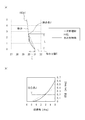
- FIGS. 9A and 9B are diagrams for explaining inclinations of various escape portions with respect to the outer ring raceway.
- FIG. 9A shows cross-sectional shapes of various relief portions
- FIG. 9B shows inclinations of various escape portions with respect to the outer ring raceway.
- the diameter of the outer ring is 60 mm
- the coordinate angle of the relief portion is 5 deg
- the relief depth is 1 mm.
- the solid line indicates a cubic parabola (relaxation curve)
- the broken line indicates an arc
- the alternate long and short dash line indicates a primary incremental line.
- the gradual increase line from the mating surface C to the junction point J (the movement from the bottom to the top in FIG. 9A and the movement from the right to the left in FIG.
- the large end portion 141 has a body portion 143 that is a first housing portion having a concave portion having a substantially semicircular cross section, and a bolt portion 145 that is a cap portion 144 that is a second housing portion having a concave portion having a substantially semicircular cross section.
- the support hole 146 having a substantially circular cross section is formed by fastening and fixing.
- a split roller bearing 151 is incorporated in a support hole 146 having a substantially circular cross section formed by the main body portion 143 and the cap portion 144.
- This rolling bearing 151 is arranged so that it can roll on each inner side surface of a pair of split outer ring members 152a, 152b and two split outer ring members 152a, 152b that are closely arranged in the support hole 146.
- a roller 153 that is a plurality of rolling elements provided, and a cage 154 that holds the rollers 153 so as to be arranged at substantially equal intervals in the circumferential direction, and the crankshaft 142 is an inner ring member of the rolling bearing 151. Is configured.
- the bearing structure is applied to the large end portion of the connecting rod.
- the upper is a housing that constitutes a part of the crankshaft fixing portion 160. It can also be used as a bearing for supporting a crankshaft disposed in a support hole formed by a block 161 and a lower block 162 which is a housing integrally coupled to the upper block 161.
- reference numeral 163 denotes a fixing bolt for integrally fixing the upper block 161 and the lower block 162, and 164 denotes a support shaft for the crankshaft.
- crankshaft is exemplified as the shaft fitted into the bearing.
- bearing structure of the present invention can be applied to other shafts such as a camshaft.
- embodiment mentioned above is provided with the needle bearing which used the roller as a rolling element, the ball bearing which used the ball as a rolling element can also be employ
- FIG. 12 is a front sectional view of a rolling bearing according to the fifth embodiment of the present invention.
- the rolling bearing 201 of the present embodiment is attached to the outer peripheral surface of the journal portion 212 of the crankshaft 211 and is fitted in a support hole 213A of a housing 213 provided in the crankcase.
- the housing 213 includes an upper block 213B and a lower block 213C, and the lower block 213C is bolted to the lower surface of the upper block 213B, thereby forming a support hole 213A between the two 213B and 213C.
- the crankshaft 211 includes a journal portion 212, a crank arm 214, a crankpin 215, a balance weight 216, and the like.
- the journal portion 212 is disposed at the rotation center position of the crankshaft 211 and is rotatably supported by the housing 213 via the rolling bearing 201.
- a plurality of crank arms 214 are arranged side by side at intervals in the axial direction, and are connected to each other by a journal portion 212 and a crank pin 215.
- the crank pin 215 is provided at the front end portion of the crank arm 214, and the balance weight 216 is provided at the rear end portion of the crank arm 214.
- the balance weight 216 may be formed integrally with the crank arm 214, or may be formed separately from the crank arm 214.
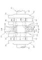
- FIG. 13 is a side view of the rolling bearing 201.
- the rolling bearing 201 is arranged so that it can roll on the inner peripheral surfaces of two sets of split outer rings (outer ring members) 202a, 202b and two split outer ring members 202a, 202b that are divided in two in the circumferential direction. And a pair of split cages 204a and 204b that hold the rollers 203 so as to be arranged at substantially equal intervals in the circumferential direction.
- the rolling bearing 201 according to the present embodiment includes a pair of two split inner rings (inner ring members) 205a and 205b that are divided into two in the circumferential direction, and the inner peripheral surfaces of the two split inner ring members 205a and 205b are journal portions.
- a roller 203 is disposed so as to be fitted to the outer peripheral surface of 212 and roll on the outer peripheral surfaces of the two split inner ring members 205a and 205b.
- the cage is not limited to the split structure, but has a ring structure that is divided at one place in the circumferential direction, and the divided part is expanded and attached to the outer peripheral side of the split inner ring members 205a and 205b. Also good.
- FIG. 14 is an exploded perspective view of the split inner ring member 205a, 205b.
- the split inner ring members 205a and 205b are made of bearing steel such as SUJ2, and have desired performance such as hardness (for example, HRC58 or higher), mechanical strength, wear resistance, etc. as the raceway of the rolling bearing 201.
- the two split inner ring members 205a and 205b are each formed in a semicircular arc shape, and both end surfaces in the circumferential direction are divided surfaces 205a2 and 205b2 extending straight along the axial direction.
- the two split inner ring members 205a and 205b are abutted with each other on the dividing surfaces 205a2 and 205b2 at both ends in the circumferential direction, or face each other with a slight gap in the circumferential direction.
- the inner peripheral diameters of the two split inner ring members 205 a and 205 b are set to be substantially the same as the outer diameter of the journal part 212, and the inner diameters of the two split inner ring members 205 a and 205 b are formed on the outer peripheral surface of the journal part 212. It is comprised so that a surrounding surface may closely_contact
- the axial length of the split inner ring members 205a and 205b is set slightly larger than the axial interval W between the crank arms 214 arranged on both sides in the axial direction of the journal portion 212, and there is a predetermined distance between the two dimensions. The tightening margin is set.
- the split inner ring members 205a and 205b are attached to the outer peripheral surface of the journal portion 212 by cold fitting or shrink fitting. That is, the split inner ring members 205a and 205b are fitted to the outer peripheral surface of the journal part 212 in a state where the axial dimension is reduced by being cooled, or by heating the journal part 212, the crank arm 214 is heated.
- the journal portion 212 is fitted to the outer peripheral surface in a state where the interval W is widened.
- the rolling bearing 201 of the present embodiment can be firmly attached and fixed to the journal portion 212 even though the inner ring members 205a and 205b have a split structure, and the creep of the split inner ring members 205a and 205b with respect to the journal portion 212 is achieved. Can be prevented.
- a large number of narrow grooves 218 extending along the axial direction are formed on the inner peripheral surfaces of the split inner ring members 205a and 205b at intervals in the circumferential direction. The resistance in the circumferential direction of both split inner ring members 205a and 205b with respect to the portion 212 is increased, and creeping of the split inner ring members 205a and 205b is prevented.
- the roller 203 does not roll on the outer peripheral surface of the journal portion 212, and the journal portion 212 is worn. Damage can be prevented. Further, even when the rolling bearing 201 itself has reached the end of its life, the journal portion 212 hardly undergoes wear or the like, and can be handled by replacing the rolling bearing 201.
- the split inner ring members 205a and 205b are held by the crank arm 214, so that it is not necessary to attach fasteners such as bolts to the split inner ring members 205a and 205b. Therefore, the structure of the split inner ring member 205a, 205b itself can be simplified, and the thickness of the split inner ring member 205a, 205b can be reduced. Therefore, the diameter of the roller 203 is increased accordingly. The life of the rolling bearing 201 can be improved.
- FIG. 15 is an exploded perspective view showing another embodiment of the split inner ring.
- one end portion in the circumferential direction of the split inner ring member 205a, 205b protrudes in the circumferential direction on one axial side, and the other end portion in the circumferential direction projects in the circumferential direction on the opposite side in the axial direction. It has become. Therefore, the split surfaces at both ends in the circumferential direction of the split inner ring members 205a and 205b are split surfaces 205a2 and 205b2 extending along the axial direction, and split surfaces 205a3 extending along the circumferential direction (direction perpendicular to the axial direction). , 205b3, and these are arranged in a substantially Z shape (crank shape).
- the circumferential end portion of one split inner ring member 205a and the circumferential end portion of the other split inner ring member 205b are engaged with each other in the circumferential direction, thereby extending along the circumferential direction.
- the split surfaces 205a3 and 205b3 extending in surface contact with each other. Therefore, when the axial end surfaces 205a1 and 205b1 of the split inner ring members 205a and 205b are clamped by the crank arm 214, the split surfaces 205a3 and 205b3 extending along the circumferential direction of the two split inner ring members 205a and 205b are axially aligned.
- the two split inner ring members 205a and 205b are firmly fixed to each other by the friction force. Therefore, in this embodiment, the split inner ring members 205a and 205b can be attached to the journal portion 212 more firmly than in the fourth embodiment.
- FIG. 16 is an exploded perspective view showing still another embodiment of the split inner ring.
- one end portion in the circumferential direction of the split inner ring member 205a, 205b protrudes in the circumferential direction at the axial center portion, and the other end portion in the circumferential direction recedes in the circumferential direction at the axial center portion. It has become. Therefore, the split surfaces at both ends in the circumferential direction of the split inner ring members 205a and 205b include split surfaces 205a2 and 205b2 extending along the axial direction, and split surfaces 205a3 and 205b3 extending along the circumferential direction. It is arranged in a substantially convex shape and a substantially concave shape.
- the circumferential end portion of one split inner ring member 205a and the circumferential end portion of the other split inner ring member 205b are engaged with each other in a circumferential direction so that the circumferential direction end portion
- the split surfaces 205a3 and 205b3 extending along the surface are in surface contact with each other in the axial direction.
- the split surfaces 205a3 and 205b3 extending along the circumferential direction of the two split inner ring members 205a and 205b are axially aligned.
- the two split inner ring members 205a and 205b are firmly fixed to each other by the friction force, and the split inner ring members 205a and 205b can be attached to the journal portion 212 more firmly.
- the present invention is not limited to the embodiment described above, and can be appropriately changed in design.
- the present invention can also be applied to the case where the rolling bearing 201 is attached to the crank pin 215 of the crankshaft 211.
- the split inner ring members 205a and 205b of the rolling bearing 201 are fitted to the outer peripheral surface of the crank pin 215, and the split inner ring members 205a and 205b are clamped and held by the crank arms 214 on both sides in the axial direction of the crank pin 215.
- What is necessary is just to fit the outer peripheral surface of the split outer ring members 202a and 202b of the rolling bearing 1 into the support hole of the large end portion of the connecting rod (not shown).
- the bearing apparatus of embodiment mentioned above is provided with the needle bearing which used the roller as a rolling element, the ball bearing which used the ball as a rolling element can also be employ
Landscapes
- Engineering & Computer Science (AREA)
- General Engineering & Computer Science (AREA)
- Mechanical Engineering (AREA)
- Rolling Contact Bearings (AREA)
Abstract
耐久性が低下するのを抑制するとともに転動体の合わせ面通過に伴う騒音や振動の発生を大幅に抑制することができる二つ割り外輪、及びこれを用いた二つ割り転がり軸受を提供する。 本発明に係る二つ割り外輪2は、互いに周方向端部同士を突き合わせることで円筒状とされる第一及び第二の分割外輪部材5,6を有している。互いに突き合わされる周方向端部の内の一方側の端部5aには、第一の平面部7と、周方向に凹んでいるV字状の凹部8とが形成されている。端部5aに突き合わされている端部6aには、第一の平面部7と当接している第二の平面部9と、この第二の平面部9から周方向に突出して凹部8に導入されている凸部10とが形成されている。凹部8と、凸部10との間には、凹部8の底部8bと、凸部10の頂部10bとが接触するのを回避するための隙間Sが形成されている。
Description
本発明は、例えば内燃機関におけるクランクピンとコンロッド大端部との間に介装される二つ割り転がり軸受及びこれに用いられる二つ割り外輪と、このような転がり軸受の取付構造及び取付方法に関する。
自動車や船舶などのエンジンにおいて、ピストンの往復動を回転運動に変換するクランクシャフトを支持する軸受は、カウンターウェイト間又はカウンターウェイトとコンロッド大端部との間に配置されることから、円周方向に2分割された二つ割り軸受が使用されている。
前記支持軸受としては、従来、滑り軸受が使用されてきたが、近年、より燃料消費量の少ないエンジンに対する要求が益々高まっていることから、回転損失を低減させるために、前記滑り軸受に代えて周方向に分割された転がり軸受を使用することが提案されている(例えば、特許文献1参照)。
特許文献2は、内燃機関のクランクピンとコンロッド大端部との間に、二つ割り軸受が介装された例を示している。この二つ割り軸受は、コンロッド大端部内周面に内接する二つ割り外輪と、この二つ割り外輪の内周面と前記クランクピンの外周面との間に転動自在に配設される複数のころとを有している。前記二つ割り外輪は、ほぼ半円筒状に形成された一対の分割外輪部材を組み合わせることで分割可能に構成されている。二つ割り軸受は、分割可能な二つ割り外輪を用いることで径方向に分割可能であり、クランクシャフトの回転軸に対してオフセットされているクランクピンの外周側に組み込むことが可能となる。
上記一対の分割外輪部材は、互いに周方向端部同士を突き合わせているので、互いに軸方向に相対移動して、ずれが生じるおそれがある。このため、互いに突き合わされる周方向端部の内、一方側の端部には、周方向に突出した山形状の凸部が形成されているとともに、他方側の端部には、前記凸部に対応したV字状の凹部が形成されており、これら凸部と凹部とを係合することで、一対の分割外輪部材が互いに軸方向に相対移動するのを防止していた。
上記一対の分割外輪部材は、互いに周方向端部同士を突き合わせているので、互いに軸方向に相対移動して、ずれが生じるおそれがある。このため、互いに突き合わされる周方向端部の内、一方側の端部には、周方向に突出した山形状の凸部が形成されているとともに、他方側の端部には、前記凸部に対応したV字状の凹部が形成されており、これら凸部と凹部とを係合することで、一対の分割外輪部材が互いに軸方向に相対移動するのを防止していた。
また、前記二つ割り転がり軸受では、二つ一組の二つ割り外輪の円周方向端面同士が当接されて合わせ面を形成しているが、当該転がり軸受を収容する支持孔を有するハウジングへの組み付け誤差や、ハウジング嵌め合い面の加工状態により、前記合わせ面において、対向する外輪両端部にラジアル方向のズレが生じることがある。その結果、当該合わせ面にラジアル方向内側に突出する段差が形成されることがある。
そして、図17に示されるように、二つ割り外輪72a、72bの合わせ面Cにラジアル方向(図17において上下方向)に段差75が生じると、この段差75が生じている外輪の合わせ面C付近をころ73が転走するときに、ころ73の周面が前記段差75の角75aに衝突し、騒音や振動が発生する惧れがある。
そこで、ころが段差を通過することに伴って発生する騒音や振動を抑制するために、前記合わせ面付近における外輪の軌道面をラジアル方向外側に逃がして「逃げ」ないしは「逃げ面」を形成することが提案されている(例えば、特許文献3参照)。
特許文献3記載の軸受では、合わせ面を形成する一方の外輪の円周方向端部にV字状凸部を設けるとともに、他方の外輪の円周方向端部にV字状凹部を設けている。そして、両外輪の円周方向端部のうち外輪軌道面を構成する内周面側に、先端縁に向かうにしたがって径方向の厚さ寸法を漸減させる方向に傾斜した傾斜面(逃げ面)を形成している。特許文献3記載の軸受によれば、外輪同士の合わせ面にラジアル方向のズレが生じたとしても、前記傾斜面を形成したことにより段差が生じるのを防ぐことができ、その結果、騒音や振動の発生が抑制される、とされている。
特許文献3記載の軸受では、合わせ面を形成する一方の外輪の円周方向端部にV字状凸部を設けるとともに、他方の外輪の円周方向端部にV字状凹部を設けている。そして、両外輪の円周方向端部のうち外輪軌道面を構成する内周面側に、先端縁に向かうにしたがって径方向の厚さ寸法を漸減させる方向に傾斜した傾斜面(逃げ面)を形成している。特許文献3記載の軸受によれば、外輪同士の合わせ面にラジアル方向のズレが生じたとしても、前記傾斜面を形成したことにより段差が生じるのを防ぐことができ、その結果、騒音や振動の発生が抑制される、とされている。
上記従来の二つ割り外輪において、分割外輪部材端部の凹部は、V字状に切り欠いて形成されているため、その底部に応力集中が生じ易くなっている。これに加えて、上記二つ割り外輪は、コンロッド大端部の内周面に圧入状態で装着されるので、二つ割り外輪全体に対して縮径する方向の応力が作用する。このため、二つ割り外輪がコンロッド大端部に装着されると、凹部に嵌合している三角形状の凸部の頂部が当該凹部の底部を押圧することとなる。これにより、凹部の底部に応力集中が生じ、この底部を起点として、周方向に沿った割れが分割外輪部材に生じ、二つ割り外輪としての耐久性を低下させる要因となっていた。
また、特許文献3記載の軸受では、前記「逃げ面」が直線的に直径を漸減または漸増させた傾斜面により構成されているが、これに代えて、外輪軌道面と逆曲率の円弧状曲面を合わせ面の内径側縁部に形成することが考えられる。
しかしながら、前述した傾斜面および円弧状曲面からなる「逃げ面」では、当該傾斜面または円弧状曲面と、外輪軌道面との境界である接合点においてころの速度ベクトルが急激に変化するため、騒音や振動の発生を十分には抑制できない。
本発明はこのような事情に鑑みてなされたものであり、分割外輪部材に割れが生じるのを防止し、耐久性が低下するのを抑制するとともに、転動体の合わせ面通過に伴う騒音や振動の発生を大幅に抑制することができる二つ割り外輪、及びこれを用いた二つ割り転がり軸受を提供することを目的とする。
上記目的を達成するための本発明の一観点は、径方向に分割可能な二つ割り転がり軸受に用いる二つ割り外輪であって、半円筒状に形成されているとともに、周方向両端部同士を互いに突き合わせることで円筒状とされる一対の分割外輪部材を有し、互いに突き合わされている前記周方向端部同士の内の一方端部には、軸方向両端縁から中央に向かって軸線に平行に延びる一対の第一の平面部と、この一対の第一の平面部の間で当該第一の平面部に対して周方向に凹んでいるV字状の凹部と、が形成され、前記端部に突き合わされている他方端部には、軸方向両端縁から軸線に平行に延び、前記一対の第一の平面部と当接している一対の第二の平面部と、この一対の第二の平面部の間に形成され前記凹部に対応した形状に周方向に突出して前記凹部に導入されている凸部と、が形成され、前記凹部と、前記凸部との間には、前記凹部の底部と、前記凸部の頂部とが接触するのを回避するための隙間が形成されている。
上記のように構成された二つ割り外輪によれば、凹部と、凸部との間には、凹部の底部と、凸部の頂部とが接触するのを回避するための隙間が形成されているので、二つ割り転がり軸受に使用したときに、当該二つ割り外輪全体に対して縮径する方向の応力が作用したとしても、凸部の頂部が凹部の底部に直接接触して当該凹部の底部を押圧するのを防止することができる。さらに、前記応力は、互いに当接している第一及び第二の平面部によって負担することができるので、凹部の底部に応力が過大に集中するのを防止することができる。
以上のように本発明の一観点によれば、凹部の底部に応力が過大に集中するのを防止しつつ、凸部の頂部が凹部の底部を押圧するのを防止でき、この結果、当該底部を起点とした割れが分割外輪部材に生じるのを防止することができる。
以上のように本発明の一観点によれば、凹部の底部に応力が過大に集中するのを防止しつつ、凸部の頂部が凹部の底部を押圧するのを防止でき、この結果、当該底部を起点とした割れが分割外輪部材に生じるのを防止することができる。
より具体的には、前記隙間は、前記凸部の頂部を曲面とすることにより形成されていることが好ましく、この場合、凸部の頂部に曲面を設けるといった簡易な方法によって、凹部と凸部との間に隙間を設けることができる。
また、前記隙間は、前記凹部の底部に設けられたぬすみ部によって形成することもでき、この場合も、上記と同様、簡易な方法で、凹部と凸部との間に隙間を設けることができる。
また、前記隙間は、前記凹部の底部に設けられたぬすみ部によって形成することもでき、この場合も、上記と同様、簡易な方法で、凹部と凸部との間に隙間を設けることができる。
また、前記隙間は、前記凸部の頂角を前記凹部の内角よりも大きくすることにより形成されているものであってもよい。
この場合、凹部の底部と、凸部の頂部との間のみならず、凹部と凸部との間のほぼ全域に亘って隙間を設けることができるので、凹部への過大な応力集中をより効果的に防止できる。
この場合、凹部の底部と、凸部の頂部との間のみならず、凹部と凸部との間のほぼ全域に亘って隙間を設けることができるので、凹部への過大な応力集中をより効果的に防止できる。
また、両分割外輪部材の端部の内周側それぞれには、端部の周方向先端縁に向かって先細りとなるように曲面部が形成されていてもよい。これら曲面部は、両端部を互いに突き合わせて二つ割り外輪としたときに、軌道面の軌跡に対して径方向外側に凹む逃げ溝を構成し、軌道面の軸方向全域に亘って設けられていることが好ましい。
さらに、この逃げ溝の断面形状は、両端部の境界を通過する径方向線上に中心が位置する所定のR寸法(曲率半径)の凹曲面で、所定の周方向の範囲Lに位置するように設定される。このとき、範囲Lは、凹部及び凸部の内周側が逃げ溝の一部となるように設定される。これによって、逃げ溝は、凹部と凸部の境界を含んだ両端部の境界全域に亘って設けられており、これによって、逃げ溝を転動通過する円筒ころに作用する、軌道面及びクランクピンの外周面からの接触面圧を下げることができる。この結果、円筒ころが両端部の境界を通過する際に生じる振動等の発生を効果的に防止できる。
さらに、この逃げ溝の断面形状は、両端部の境界を通過する径方向線上に中心が位置する所定のR寸法(曲率半径)の凹曲面で、所定の周方向の範囲Lに位置するように設定される。このとき、範囲Lは、凹部及び凸部の内周側が逃げ溝の一部となるように設定される。これによって、逃げ溝は、凹部と凸部の境界を含んだ両端部の境界全域に亘って設けられており、これによって、逃げ溝を転動通過する円筒ころに作用する、軌道面及びクランクピンの外周面からの接触面圧を下げることができる。この結果、円筒ころが両端部の境界を通過する際に生じる振動等の発生を効果的に防止できる。
また、本発明の別観点は、半円筒状に形成されているとともに、互いに周方向両端部同士を突き合わせることで円筒状とされる一対の分割外輪部材からなる二つ割り外輪と、前記外輪内周面側に配列される複数の転動体と、各転動体を円周方向略等間隔に配置するように保持する保持器とを有する径方向に分割可能な二つ割り転がり軸受であって、前記二つ割り外輪は、上述の二つ割り外輪である。
上記のように構成された二つ割り転がり軸受によれば、上述の二つ割り外輪を用いることで、分割外輪部材に割れが生じるのを防止することができる。この結果、二つ割り転がり軸受としての耐久性が低下するのを防止することができる。
上記のように構成された二つ割り転がり軸受によれば、上述の二つ割り外輪を用いることで、分割外輪部材に割れが生じるのを防止することができる。この結果、二つ割り転がり軸受としての耐久性が低下するのを防止することができる。
さらに、本発明の別観点の二つ割り転がり軸受は、半円筒状に形成されているとともに、互いに周方向両端部同士を突き合わせることで円筒状とされる一対の分割外輪部材からなる二つ割り外輪と、前記外輪内周面側に配列される複数の転動体と、各転動体を円周方向略等間隔に配置するように保持する保持器とを備え、シャフトが内嵌される二つ割り転がり軸受であって、
前記二つ割り外輪の円周方向端面における内径側縁部に形成された逃げ面おいて、少なくとも前記転動体が接触する範囲の断面形状が緩和曲線で構成されている。
前記二つ割り外輪の円周方向端面における内径側縁部に形成された逃げ面おいて、少なくとも前記転動体が接触する範囲の断面形状が緩和曲線で構成されている。
上記の二つ割り転がり軸受では、二つ割り外輪部材の円周方向端面における内径側縁部に形成された逃げ面おいて、少なくとも転動体が接触する範囲の断面形状(二つ割り転がり軸受の軸方向に垂直な断面の形状)が緩和曲線で構成されているので、当該緩和曲線で構成された曲面と外輪軌道面との境界(接合点)近傍での転動体の速度ベクトルは徐々に変化する。このため、転動体の速度ベクトルの急激な変化に起因する振動や騒音の発生を抑制することができ、転動体の合わせ面通過に伴う振動や騒音の発生を大幅に抑制することができる。
前記緩和曲線をクロソイド曲線または三次放物線とすることができる。この場合、接合点近傍での転動体の速度ベクトルを徐々に変化させることができ、転動体の速度ベクトルの急激な変化に起因する振動や騒音の発生を抑制することができる。
また、本発明の一観点に係る軸受構造は、前述した二つ割り転がり軸受と、この二つ割り転がり軸受を密接して支持する支持孔を有するハウジングとを備えたことを特徴としている。
本発明の軸受構造では、前述した二つ割り転がり軸受を用いているので、接合点近傍での転動体の速度ベクトルを徐々に変化させることができ、転動体が合わせ面を通過することに伴う騒音や振動の発生を大幅に抑制することができる。
本発明の軸受構造では、前述した二つ割り転がり軸受を用いているので、接合点近傍での転動体の速度ベクトルを徐々に変化させることができ、転動体が合わせ面を通過することに伴う騒音や振動の発生を大幅に抑制することができる。
本発明の別の観点は、クランクシャフトの軸部に対する転がり軸受の取付構造であって、
前記転がり軸受が上述の二つ割り転がり軸受であって、さらに前記軸部の外周面に取り付けられ、かつ円周方向に二つ割りになっている二つ一組の二つ割り内輪とを備え、前記両二つ割り内輪が、前記軸部の軸方向両側に配置されたクランクアームによって軸方向に挟圧保持されている。
前記転がり軸受が上述の二つ割り転がり軸受であって、さらに前記軸部の外周面に取り付けられ、かつ円周方向に二つ割りになっている二つ一組の二つ割り内輪とを備え、前記両二つ割り内輪が、前記軸部の軸方向両側に配置されたクランクアームによって軸方向に挟圧保持されている。
クランクシャフトのジャーナル部は、通常、転がり軸受の内輪に要求される耐摩耗性等の性能を持ち合わせておらず、早期に剥離や摩耗などが生じるという問題がある。そのため、ジャーナル部に対して別途内輪を取り付けることも考えられるが、ジャーナル部の軸方向両側にはクランクアームが存在するため、外輪と同様に内輪も二つ割り構造とする必要があり、さらに、クリープが生じないように内輪をジャーナル部に対して強固に取り付けることが要求される。しかしながら、内輪は、二つ割り構造であるとジャーナル部に強く圧接することができないため、強固にジャーナル部に取り付けるのは困難である。
上記の構成を採用することにより、二つ割り内輪が、軸部の軸方向両側に配置されたクランクアームによって軸方向に挟圧保持されるので、軸部に対して二つ割り内輪を強固に取り付けることができ、軸部に対する二つ割り内輪のクリープの発生を抑制することができる。
上記の構成を採用することにより、二つ割り内輪が、軸部の軸方向両側に配置されたクランクアームによって軸方向に挟圧保持されるので、軸部に対して二つ割り内輪を強固に取り付けることができ、軸部に対する二つ割り内輪のクリープの発生を抑制することができる。
上記構成において、一方の二つ割り内輪の円周方向端部と、他方の二つ割り内輪の円周方向端部とに、前記クランクアームによる両二つ割り内輪の挟圧によって互いに軸方向に圧接される円周方向に沿った面が形成されていることが好ましい。この場合、両二つ割り内輪が円周方向に沿って延びる面において互いに軸方向に圧接されることになるため、両二つ割り内輪の相対位置が強固に固定される。したがって、二つ割り構造の内輪であっても、クランクシャフトの軸部に対してもより強固に二つ割り内輪を取り付けることができる。
本発明の別の観点では、上述した転がり軸受をクランクシャフトの軸部に取り付ける方法であって、前記両二つ割り内輪の軸方向寸法と、前記軸部の軸方向両側に配置された前記クランクアームの軸方向間隔との間に軸方向の締めしろを設定し、前記両二つ割り内輪の冷やしばめ又は前記軸部の焼ばめによって前記両二つ割り内輪を前記クランクアーム間に挿入して前記軸部に取り付ける。
このような取付方法によって、クランクシャフトの軸部に対して二つ割り内輪を強固に取り付けることができる。
本発明の二つ割り外輪、及び二つ割り転がり軸受によれば、転動体の合わせ面通過に伴う騒音や振動の発生を大幅に抑制することができるとともに、分割外輪部材に割れが生じるのを防止し、耐久性が低下するのを抑制することができる。
(第一の実施形態)
次に、本発明の好ましい実施形態について添付図面を参照しながら説明する。図1は、本発明の第一の実施形態に係る二つ割り転がり軸受の構造を示す側面図である。この二つ割り転がり軸受1は、例えば、内燃機関のクランクピンPの外周と、コンロッドCの大端部C1の内周との間に介装され、コンロッドCをクランクピンPに対して揺動自在に支持している。
この二つ割り転がり軸受1は、大端部C1の内周面C2に内接する二つ割り外輪2と、この二つ割り外輪2の内周側に形成された軌道面2aとクランクピンPの外周面P1との間に転動自在に配設される複数の円筒ころ3と、これら円筒ころ3を周方向等間隔に配置するように保持するための二つ割り保持器4とを有している。二つ割り外輪2、及び二つ割り保持器4は、径方向に分割可能とされており、二つ割り転がり軸受1についても、径方向に分割可能である。
二つ割り転がり軸受1は、内周面C2内に圧入状態で介装されている。このため、コンロッドCの大端部C1に二つ割り転がり軸受1として組み込んだときの二つ割り外輪2には、縮径する方向の応力が作用している。
図2は、二つ割り外輪2を示す斜視図である。この二つ割り外輪2は、ほぼ半円筒状に形成された第一の分割外輪部材5、及び第二の分割外輪部材6を有しており、これら一対の分割外輪部材5,6それぞれの周方向の端部5a,6a同士を互いに突き合わせることで円筒状の外輪を構成している。二つ割り外輪2の内周側の軸方向両端縁には、上述の軌道面2aに対して径方向に突出した鍔部2bが周方向に沿って形成されている。この鍔部2bは、軌道面2aに配設される複数の転動体である円筒ころ3の軸方向への移動を規制している。
第一の分割外輪部材5の一方端部としての端部5aには、軸方向両端縁から中央に向かって軸線に平行に延びる一対の第一の平面部7と、この一対の第一の平面部7の間で当該第一の平面部7に対して周方向に凹んでいるV字状の凹部8とが形成されている。
また、端部5aに突き合わされる他方端部としての第二の分割外輪部材6の端部6aには、軸方向両端縁から軸線に平行に延びる一対の第二の平面部9と、この一対の第二の平面部9の間に形成され周方向に突出して第一の分割外輪部材5の凹部8に導入されている凸部10とが形成されている。
一対の第一の平面部7及び一対の第二の平面部9は、両端部5a,6aを互いに突き合わせた状態で互いに当接している。また、凸部10は、第一の分割外輪部材5の凹部8に対応した形状(山形状)に形成されており、両端部5a,6aを互いに突き合わせた状態で、互いに合致する形状とされている。このように、両端面5a,6aに、互いに合致し導入される凹部8、及び凸部10を設けることで、第一の分割外輪部材5と第二の分割外輪部材6とが、軸方向にずれるのを防止している。
図3は、二つ割り外輪2の要部拡大図であり、(a)は、両端部5a,6aを突き合わせた部分を外周側から正面視した図、(b)は、図3(a)中、b-b線矢視断面図である。
図3(a)において、両分割外輪部材5,6それぞれにおける両平面部7,9は、上述のように互いに当接している。
第一の分割外輪部材5の凹部8は、第一の平面部7から周方向に凹む方向に直線状に傾斜している一対の傾斜壁面8aによりV字状に形成されており、これら一対の傾斜壁面8aが互いに交わる部分が、凹部8の底部8bとなる。
一方、第二の分割外輪部材6の凸部10は、第二の平面部9から周方向に突出する方向に直線状に傾斜している一対の傾斜側面10aにより山形状に形成されており、これら一対の傾斜側面10aが互いに交わる部分が、凸部10の頂部10bとなる。
また、上記凹部8及び凸部10は、軸方向ほぼ中央に設けられるとともに、軸方向の中央に対して対称となるように形成されている。
ここで、本実施形態において、一対の傾斜側面10aが成す角度である凸部10の頂角αは、一対の傾斜壁面8aが成す角度である凹部8の内角βよりも大きい値となるように設定されている。
このように、頂角α、及び内角βを設定することで、凸部10と、凹部8との間には、図3(a)に示すように、隙間Sが形成されている。この隙間Sは、凹部8の底部8bと、凸部10の頂部10bとの間を含む、凸部10と、凹部8との間のほぼ全域に亘って形成されており、凸部10の頂部10bと、凹部8の底部8bとが接触するのを回避している。
上記隙間Sは、凸部10の基端部に近づくに従って序々に小さくなり、凸部10基端部近傍では、凸部10と、凹部8とは接触している。本実施形態では、凸部10の基端部近傍が、凹部8に接触することで、両分割外輪部材5,6が軸方向にずれるのを防止している。
なお、上記隙間Sは、最大で60μm程度に設定されることが好ましい。それ以上大きく設定すると、両分割外輪部材5,6の軸方向へのずれを効果的に防止できないおそれがあるからである。
両分割外輪部材5,6の端部5a,6aの内周側それぞれには、図3(b)に示すように、端部5a,6aの周方向先端縁に向かって先細りとなるように曲面部5b,6bが形成されている。これら曲面部5b,6bは、両端部5a,6aを互いに突き合わせて二つ割り外輪2としたときに、軌道面2aの軌跡に対して径方向外側に凹む逃げ溝2cを構成している。この逃げ溝2cは、軌道面2aの軸方向全域に亘って設けられている。
また、逃げ溝2cの断面形状は、両端部5a,6aの境界を通過する径方向線上に中心が位置する所定のR寸法の凹曲面で、所定の周方向の範囲Lに位置するように設定されている。このとき、範囲Lは、凹部8及び凸部10の内周側が逃げ溝2cの一部となるように設定されている。これによって、逃げ溝2cは、凹部8と凸部10の境界を含んだ両端部5a,6aの境界全域に亘って設けられており、これによって、逃げ溝2cを転動通過する円筒ころ3に作用する、軌道面2a及びクランクピンPの外周面P1からの接触面圧を下げることができる。この結果、円筒ころ3が両端部5a,6aの境界を通過する際に生じる振動等の発生を効果的に防止できる。
また、逃げ溝2cの断面形状は、両端部5a,6aの境界を通過する径方向線上に中心が位置する所定のR寸法の凹曲面で、所定の周方向の範囲Lに位置するように設定されている。このとき、範囲Lは、凹部8及び凸部10の内周側が逃げ溝2cの一部となるように設定されている。これによって、逃げ溝2cは、凹部8と凸部10の境界を含んだ両端部5a,6aの境界全域に亘って設けられており、これによって、逃げ溝2cを転動通過する円筒ころ3に作用する、軌道面2a及びクランクピンPの外周面P1からの接触面圧を下げることができる。この結果、円筒ころ3が両端部5a,6aの境界を通過する際に生じる振動等の発生を効果的に防止できる。
また、端部6における凸部10の内周側に位置する部分には、図3(b)に示すように、曲面部6bからさらに、逃げ溝2cの軌跡に対して接線方向に延びる平面とされた直線部6b1が形成されている。直線部6b1は、逃げ溝2cの軌跡に対して接線方向に延びており、凸部10の頂部10bの内周側先端縁10cが、逃げ溝2cの軌跡よりも径方向外側に位置している。
これにより、凸部10の内周側先端縁10cが、円筒ころ3に接触するのを防止し、円筒ころ3が両端部5a,6aの境界を通過する際に生じる振動等の発生をより効果的に防止できる。
これにより、凸部10の内周側先端縁10cが、円筒ころ3に接触するのを防止し、円筒ころ3が両端部5a,6aの境界を通過する際に生じる振動等の発生をより効果的に防止できる。
上記のように構成された本実施形態による二つ割り外輪2によれば、コンロッドCの大端部C1に組み込まれて当該二つ割り外輪2全体に対して縮径する方向の応力が作用したとしても、凹部8の底部8bと、凸部10の頂部10bとの間に、頂部10bと底部8bとが接触するのを回避するための隙間Sが形成されているので、凸部10の頂部10bが凹部8の底部8bに直接接触して当該底部8bを押圧するのを防止することができる。さらに、前記応力は、互いに当接している第一及び第二の平面部7,9によって負担することができるので、凹部8の底部8bに応力が過大に集中するのを防止することができる。
以上のように本実施形態の二つ割り外輪2によれば、凹部8の底部8bに応力が過大に集中するのを防止しつつ、凸部10の頂部10bが凹部8の底部8bを押圧するのを防止でき、この結果、当該底部8bを起点とした周方向に沿う割れが第一の分割外輪部材5に生じるのを防止することができる。
以上のように本実施形態の二つ割り外輪2によれば、凹部8の底部8bに応力が過大に集中するのを防止しつつ、凸部10の頂部10bが凹部8の底部8bを押圧するのを防止でき、この結果、当該底部8bを起点とした周方向に沿う割れが第一の分割外輪部材5に生じるのを防止することができる。
また、上記実施形態では、凸部10が、その頂角αが凹部8の内角βよりも大きい値で形成されることで、凹部8の底部8bと、凸部10の頂部10bとの間のみならず、凹部8と凸部10との間のほぼ全域に亘って隙間Sを設けることができる。これにより、凹部8への過大な応力集中をより効果的に防止できる。なお、このように凹部8と凸部10との間のほぼ全域に隙間Sを設けたとしても、凸部10の基端部が凹部8に接しているので、両分割外輪部材5,6が互いに軸方向へずれることはない。
また、本実施形態の二つ割り転がり軸受1は、上記二つ割り外輪2を用いることで、第一の分割外輪部材5に割れが生じるのを防止することができる。この結果、二つ割り転がり軸受1としての耐久性が低下するのを防止することができる。
(第二の実施形態)
図4は、本発明の第二の実施形態に係る二つ割り転がり軸受1の要部拡大図であり、両分割外輪部材5,6の両端部5a,6aを突き合わせた部分を示している。本実施形態と、上記第一の実施形態との主な相違点は、隙間Sが、凸部10の頂部10bを曲面とすることにより形成されている点である。
図4は、本発明の第二の実施形態に係る二つ割り転がり軸受1の要部拡大図であり、両分割外輪部材5,6の両端部5a,6aを突き合わせた部分を示している。本実施形態と、上記第一の実施形態との主な相違点は、隙間Sが、凸部10の頂部10bを曲面とすることにより形成されている点である。
本実施形態では、凹部8の内角βと、凸部10の頂角αとがほぼ同じ値に設定されており、凹部8の傾斜壁面8aと、凸部10の傾斜側面10aとは接触している。
また、凸部10の頂部10bは、上述のように曲面とされており、凹部8の底部8bと、凸部10の頂部10bとの間に隙間Sが形成されている。
本実施形態の場合においても、上記隙間Sによって、凸部10の頂部10bが凹部8の底部8bに直接接触し押圧するのを防止することができる。すなわち、少なくとも、底部8bと、頂部10bとの間に隙間Sが形成されていれば、底部8bを起点とした割れが第一の分割外輪部材5に生じるのを防止することができる。
また、本実施形態では、凸部10の頂部10bを曲面とするといった簡易な方法によって、底部8bと、頂部10bとの間に隙間Sを設けることができ、コスト面で有利である。
また、凸部10の頂部10bは、上述のように曲面とされており、凹部8の底部8bと、凸部10の頂部10bとの間に隙間Sが形成されている。
本実施形態の場合においても、上記隙間Sによって、凸部10の頂部10bが凹部8の底部8bに直接接触し押圧するのを防止することができる。すなわち、少なくとも、底部8bと、頂部10bとの間に隙間Sが形成されていれば、底部8bを起点とした割れが第一の分割外輪部材5に生じるのを防止することができる。
また、本実施形態では、凸部10の頂部10bを曲面とするといった簡易な方法によって、底部8bと、頂部10bとの間に隙間Sを設けることができ、コスト面で有利である。
(第三の実施形態)
図5は、本発明の第三の実施形態に係る二つ割り転がり軸受1の要部拡大図であり、両分割外輪部材5,6の両端部5a,6aを突き合わせた部分を示している。
本実施形態と、上記各実施形態との相違点は、隙間Sが、凹部8の底部8bに設けられたぬすみ部11によって形成されている点である。
ぬすみ部11は、凹部8の傾斜壁面8aからさらに周方向に向かって凹んで形成されており、凸部10の頂部10bとの間で、隙間Sを形成している。また、このぬすみ部11は、その内側面が滑らかな曲面で形成されており、できるだけ一部分に応力が集中するのを防止している。
本実施形態では、凹部8の底部8bにぬすみ部11を形成するといった簡易な方法によって、底部8bと頂部10bとの間に隙間Sを設けることができ、上記第二の実施形態と同様、コスト面で有利である。
なお、本発明は、上記各実施形態に限定されるものではない。上記各実施形態では、凹部8を構成している一対の傾斜壁面8a、及び、凸部10を構成している一対の傾斜側面10aが、それぞれ直線状に傾斜して形成されたものを例示したが、凹部8、及び凸部10は、全体として、それぞれ、ほぼV字状、ほぼ山形状に形成されていればよく、例えば、図6(a)に示すように、適度に凸部10の傾斜側面10aを凸湾曲させて形成したものや、逆に凹湾曲させたものも、V字状、山形状含まれる。
また、図6(b)に示すように中間部分で、傾斜壁面8a及び傾斜側面10aの傾斜角を変化させることもできる。
また、図6(b)に示すように中間部分で、傾斜壁面8a及び傾斜側面10aの傾斜角を変化させることもできる。
(第四の実施形態)
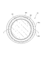
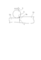
図7は、本発明の第四の実施形態に係る転がり軸受101の断面説明図であり、図8は図7に示される転がり軸受101の合わせ面付近の拡大説明図である。この転がり軸受101は、半円筒状に形成されているとともに、円周方向に二つ割りになって互いに周方向両端部同士を突き合わせることで円筒状とされる二つ一対の二つ割り外輪(外輪部材)102a、102bと、外輪の内周面側に配列され、両二つ割り外輪部材102a、102bの各内側面を転動し得るように配設される複数個の転動体であるころ103と、各ころ103を円周方向略等間隔に配置するように保持する保持器104とを備えている。保持器104は周方向1ヶ所に割り部が設けられており、シャフト105への組込み時に当該割り部を拡径することで保持器104が組込み可能とされる。ただし、周方向2ヶ所に割り部を設けた分割型としてもよい。シャフト105は、前記複数個のころ103によって支持されることにより前記転がり軸受101に内嵌されている。このシャフト105は内輪としても機能している。
図7は、本発明の第四の実施形態に係る転がり軸受101の断面説明図であり、図8は図7に示される転がり軸受101の合わせ面付近の拡大説明図である。この転がり軸受101は、半円筒状に形成されているとともに、円周方向に二つ割りになって互いに周方向両端部同士を突き合わせることで円筒状とされる二つ一対の二つ割り外輪(外輪部材)102a、102bと、外輪の内周面側に配列され、両二つ割り外輪部材102a、102bの各内側面を転動し得るように配設される複数個の転動体であるころ103と、各ころ103を円周方向略等間隔に配置するように保持する保持器104とを備えている。保持器104は周方向1ヶ所に割り部が設けられており、シャフト105への組込み時に当該割り部を拡径することで保持器104が組込み可能とされる。ただし、周方向2ヶ所に割り部を設けた分割型としてもよい。シャフト105は、前記複数個のころ103によって支持されることにより前記転がり軸受101に内嵌されている。このシャフト105は内輪としても機能している。
二つ割り外輪部材102aの円周方向端面と、この端面と対向する二つ割り外輪部材102bの円周方向端面とにより合わせ面Cが構成されている。本実施形態では、図8に示されるように、この合わせ面Cを構成する二つ割り外輪部材102a、102bの各端面の内径側縁部に逃げ面である曲面Bが形成されており、この曲面Bのうち前記ころ103が転動して接触する範囲の断面形状が緩和曲線で構成されている。より詳細には、図9の(a)に示されるように、円周方向においては前記合わせ面Cから、二つ割り外輪部材102a、102bの各軌道面102a1、102b1と前記曲面Bとの境界である接合点Jに至る範囲Lであり、径方向においては前記軌道面102a1、102b1から径外方向にhの範囲の曲面の断面形状が緩和曲線で構成されている。前記Lの大きさは、二つ割り外輪部材102a、102bの各軌道面102a1、102b1の内径やころ103の直径に応じて適宜選定することができるが、通常、ころ103の直径をDとすると2Dよりも小さい範囲で選定される。また、前記hの大きさは、外輪部材の合わせ面Cにおけるラジアル方向のズレ(段差)の大きさやころ103の直径により異なるが、通常、当該段差の大きさよりも大きい値が選定される。hの大きさを段差の大きさよりも大きい値としておけば、少なくともころ103が接触する範囲を緩和曲線とすることができる。
なお、前記曲面Bのうちころ103の接触範囲以外の曲面については、円弧状曲面としてもよいし、また、断面形状が緩和曲線で構成される曲面としてもよい。さらに、逃げ面として、本発明の断面形状が緩和曲線で構成される曲面と、この曲面の外径側(ハウジング側)に続く傾斜平面とからなるものを採用してもよい。
なお、前記曲面Bのうちころ103の接触範囲以外の曲面については、円弧状曲面としてもよいし、また、断面形状が緩和曲線で構成される曲面としてもよい。さらに、逃げ面として、本発明の断面形状が緩和曲線で構成される曲面と、この曲面の外径側(ハウジング側)に続く傾斜平面とからなるものを採用してもよい。
少なくともころ103が接触する範囲を緩和曲線とすることで、接合点Jにおけるころ103の速度ベクトルの変化を小さくすることができ、速度ベクトルの急激な変化に起因する振動や騒音の発生を抑制することができる。このような緩和曲線としては、代表的なクロソイド(clothoid)曲線(Cornuの螺旋)を好適に用いることができるが、当該クロソイド曲線に近似している三次放物線を用いることもできる。
図9は、外輪軌道に対する各種逃げ部の傾きを説明する図であり、(a)は各種逃げ部の断面形状を示しており、(b)は外輪軌道に対する各種逃げ部の傾きを示している。図9において、外輪の直径は60mm、逃げ部の座標角は5deg、逃げの深さは1mmとしている。実線は三次放物線(緩和曲線)、破線は円弧、一点鎖線は一次漸増線を示している。一次漸増線では、合わせ面Cから接合点Jに至るまで(図9の(a)では下から上への移動であり、同(b)においては右から左への移動)は外輪に対する逃げ面の傾きは一定の0.2mm/degであるが、接合点Jにおいて一気に0になる。すなわち、一次漸増線上を転動するころの速度ベクトルは当該接合点Jにおいて急激に変化する。このため、この接合点通過時に大きな振動や騒音が発生する。また、円弧では、合わせ面Cから接合点Jに至るまで前記傾きが一定の割合で小さくなっているが、接合点Jにおける傾きの変化は大きく、一次漸増線ほどではないが、接合点通過時に振動や騒音が発生する。これらに対し、三次放物線の場合は接合点Jに近づくにつれて前記傾きの変化の割合が小さくなっているので、当該接合点通過時におけるころの速度ベクトルの変化を小さくすることができる。その結果、速度ベクトルの急激な変化に起因する振動や騒音の発生を抑制することができ、ころの合わせ面通過に伴う振動や騒音の発生を大幅に抑制することができる。
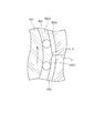
つぎに本発明の第四の実施形態の軸受構造を説明する。図10は本発明の第四の実施形態に係る軸受構造が適用されるコンロッド(コネクティングロッド)大端部の断面説明図である。コンロッド140は、その大端部141がクランクシャフト142に支持され、図示しない小端部側に図示しないピストンがピンを介して取り付けられる。
前記大端部141は、断面略半円形状の凹部を有する、第1ハウジング部である本体部143に、断面略半円形状の凹部を有する、第2ハウジング部であるキャップ部144をボルト145で締結固定することにより断面略円形の支持孔146を形成する構造である。この本体部143とキャップ部144とで形成される断面略円形の支持孔146内に、二つ割り転がり軸受151が組み込まれる。
この転がり軸受151は、支持孔146内に密接して配設される二つ一組の二つ割り外輪部材152a、152bと、両二つ割り外輪部材152a、152bの各内側面を転動し得るように配設される複数個の転動体であるころ153と、各ころ153を円周方向略等間隔に配置するように保持する保持器154とを備えており、クランクシャフト142が転がり軸受151の内輪部材を構成している。そして、前記二つ割り外輪部材152a、152bの円周方向端面における内径側縁部に形成された逃げ面おいて、少なくとも前記ころ153が接触する範囲の断面形状が緩和曲線であるクロソイド曲線で構成されている。
なお、図10に示される実施形態では、軸受構造をコネクティングロッドの大端部に適用しているが、図11に示されるように、クランクシャフト固定部160の一部を構成するハウジングであるアッパーブロック161とこのアッパーブロック161と一体に結合されるハウジングであるロアブロック162により形成される支持孔内に配置される、クランクシャフト支持用の軸受として用いることもできる。なお、図11において、163はアッパーブロック161とロアブロック162を一体に固定する固定ボルトであり、164はクランクシャフトの支持軸である。
また、前述した実施形態では、軸受に内嵌されるシャフトとして、クランクシャフトを例示したが、カムシャフトなど他のシャフトにも、本発明の軸受構造を適用することができる。
さらに、前述した実施の形態は、転動体としてころを用いたニードル軸受を備えているが、転動体としてボールを用いた玉軸受を採用することもできる。
さらに、前述した実施の形態は、転動体としてころを用いたニードル軸受を備えているが、転動体としてボールを用いた玉軸受を採用することもできる。
(第五の実施形態)
図12は、本発明の第五の実施形態に係る転がり軸受の正面断面図である。本実施形態の転がり軸受201は、クランクシャフト211のジャーナル部212の外周面に取り付けられるとともに、クランクケースに設けられたハウジング213の支持孔213Aに嵌合されている。ハウジング213は、アッパーブロック213Bとロアブロック213Cとを備え、このアッパーブロック213Bの下面にロアブロック213Cをボルト結合することによって、両者213B,213Cの間に支持孔213Aが形成されている。
図12は、本発明の第五の実施形態に係る転がり軸受の正面断面図である。本実施形態の転がり軸受201は、クランクシャフト211のジャーナル部212の外周面に取り付けられるとともに、クランクケースに設けられたハウジング213の支持孔213Aに嵌合されている。ハウジング213は、アッパーブロック213Bとロアブロック213Cとを備え、このアッパーブロック213Bの下面にロアブロック213Cをボルト結合することによって、両者213B,213Cの間に支持孔213Aが形成されている。
クランクシャフト211は、ジャーナル部212、クランクアーム214、クランクピン215、及びバランスウエイト216等を備えている。ジャーナル部212は、クランクシャフト211の回転中心位置に配置され、転がり軸受201を介してハウジング213に回転自在に支持されている。クランクアーム214は複数が軸方向に間隔をあけて並べて配置され、ジャーナル部212及びクランクピン215によって相互に接続されている。クランクピン215はクランクアーム214の先端部に設けられ、バランスウエイト216はクランクアーム214の後端部に設けられている。バランスウエイト216は、クランクアーム214と一体形成されていてもよいし、クランクアーム214と別体に形成されていてもよい。
図13は、転がり軸受201の側面図である。転がり軸受201は、円周方向に二つ割りになっている二つ一組の二つ割り外輪(外輪部材)202a、202bと、両二つ割り外輪部材202a、202bの内周面を転動し得るように配設される複数個の転動体であるころ203と、各ころ203を円周方向略等間隔に配置するように保持する二つ一組の二つ割り保持器204a、204bとを備えている。さらに本実施形態の転がり軸受201は、円周方向に二つ割りになっている二つ一組の二つ割り内輪(内輪部材)205a,205bを備え、両二つ割り内輪部材205a,205bの内周面がジャーナル部212の外周面に嵌合され、両二つ割り内輪部材205a,205bの外周面を転動し得るようにころ203が配設されている。なお、保持器は、二つ割り構造に限らず、円周方向の1箇所で分断されたリング構造とし、この分断された箇所を拡げて二つ割り内輪部材205a,205bの外周側に取り付けるように構成してもよい。
図14は、二つ割り内輪部材205a,205bの分解斜視図である。二つ割り内輪部材205a,205bは、SUJ2等の軸受鋼からなり、転がり軸受201の軌道としての硬度(例えば、HRC58以上)、機械的強度、耐摩耗性等の所望の性能を具備している。両二つ割り内輪部材205a,205bは、それぞれ半円弧形状に形成され、円周方向両端面が軸方向に沿って真っ直ぐに延びる分割面205a2,205b2とされている。両二つ割り内輪部材205a,205bは、円周方向両端の分割面205a2,205b2において互いに突き合わされるか、円周方向にわずかな隙間をもって対向する。
図12に示すように、両二つ割り内輪部材205a,205bの内周径は、ジャーナル部212の外径とほぼ同じ寸法に設定され、ジャーナル部212の外周面に両二つ割り内輪部材205a,205bの内周面が密着するように構成されている。また、二つ割り内輪部材205a,205bの軸方向の長さは、ジャーナル部212の軸方向両側に配置されたクランクアーム214の軸方向の間隔Wよりも若干大きく設定され、両寸法の間には所定の締めしろが設定されている。
そして、二つ割り内輪部材205a,205bは、冷やしばめ又は焼ばめによってジャーナル部212の外周面に取り付けられる。すなわち、二つ割り内輪部材205a,205bは、冷却されることによって軸方向寸法が縮められた状態でジャーナル部212の外周面に嵌合されるか、又はジャーナル部212を加熱することによってクランクアーム214の間隔Wを拡げた状態でジャーナル部212の外周面に嵌合される。
そして、二つ割り内輪部材205a,205b又はジャーナル部212が常温に戻ると、二つ割り内輪部材205a,205bの軸方向両端面205a1,205b1にクランクアーム214の対向端面Tが圧接し、両者の摩擦力によって二つ割り内輪部材205a,205bがクランクアーム214によって挟圧保持される。
そして、二つ割り内輪部材205a,205b又はジャーナル部212が常温に戻ると、二つ割り内輪部材205a,205bの軸方向両端面205a1,205b1にクランクアーム214の対向端面Tが圧接し、両者の摩擦力によって二つ割り内輪部材205a,205bがクランクアーム214によって挟圧保持される。
したがって、本実施形態の転がり軸受201は、内輪部材205a,205bが二つ割り構造であるにもかかわらずジャーナル部212に強固に取り付け固定することができ、ジャーナル部212に対する二つ割り内輪部材205a,205bのクリープを防止することが可能となっている。
なお、図13に示すように、二つ割り内輪部材205a,205bの内周面には軸方向に沿って延びる細溝218が周方向に間隔をあけて多数形成されており、この細溝218によってジャーナル部212に対する両二つ割り内輪部材205a,205bの周方向の抵抗が増大され、二つ割り内輪部材205a,205bのクリープが防止されている。
なお、図13に示すように、二つ割り内輪部材205a,205bの内周面には軸方向に沿って延びる細溝218が周方向に間隔をあけて多数形成されており、この細溝218によってジャーナル部212に対する両二つ割り内輪部材205a,205bの周方向の抵抗が増大され、二つ割り内輪部材205a,205bのクリープが防止されている。
また、本実施形態のように、二つ割り内輪部材205a,205bを備えた転がり軸受201とすることで、ジャーナル部212の外周面上をころ203が転動することがなくなり、ジャーナル部212の摩耗、損傷を防止することができる。また、転がり軸受201自体が寿命となった場合でもジャーナル部212には摩耗等がほとんど生じないので、転がり軸受201の交換により対応することができる。
また、本実施形態のように、二つ割り内輪部材205a,205bをクランクアーム214によって挟圧保持することで、二つ割り内輪部材205a,205bにはボルト等の締結具を取り付ける必要が無い。そのため、二つ割り内輪部材205a,205b自体の構造を簡素化することができ、また、二つ割り内輪部材205a,205bの肉厚を薄くすることが可能となるので、その分ころ203の径を大きくして転がり軸受201の寿命を向上することができる。
(第六の実施形態)
図15は、二つ割り内輪の他の実施形態を示す分解斜視図である。本実施形態では、二つ割り内輪部材205a,205bの円周方向の一端部が軸方向片側において円周方向に突出し、円周方向の他端部が軸方向反対側において円周方向に突出した形状となっている。したがって、二つ割り内輪部材205a,205bの円周方向両端部の分割面は、軸方向に沿って延びる分割面205a2,205b2と、円周方向(軸方向に垂直な方向)に沿って延びる分割面205a3,205b3とを含み、これらは略Z字状(クランク状)に配置されている。
図15は、二つ割り内輪の他の実施形態を示す分解斜視図である。本実施形態では、二つ割り内輪部材205a,205bの円周方向の一端部が軸方向片側において円周方向に突出し、円周方向の他端部が軸方向反対側において円周方向に突出した形状となっている。したがって、二つ割り内輪部材205a,205bの円周方向両端部の分割面は、軸方向に沿って延びる分割面205a2,205b2と、円周方向(軸方向に垂直な方向)に沿って延びる分割面205a3,205b3とを含み、これらは略Z字状(クランク状)に配置されている。
本実施形態では、一方の二つ割り内輪部材205aの円周方向端部と、他方の二つ割り内輪部材205bの円周方向端部とを互いに円周方向に凹凸嵌合させることで、円周方向に沿って延びる分割面205a3,205b3同士が面接触する。したがって、二つ割り内輪部材205a,205bの軸方向両端面205a1,205b1をクランクアーム214によって挟圧すると、両二つ割り内輪部材205a,205bの円周方向に沿って延びる分割面205a3,205b3同士が軸方向に圧接され、その摩擦力によって両二つ割り内輪部材205a,205bの相対位置が強固に固定されるようになっている。したがって、本実施形態では、第四の実施形態と比較して、より強固に二つ割り内輪部材205a,205bをジャーナル部212に取り付けることができる。
図16は、二つ割り内輪のさらに他の実施形態を示す分解斜視図である。本実施形態では、二つ割り内輪部材205a,205bの円周方向の一端部が軸方向中央部で円周方向に突出し、円周方向の他端部が軸方向中央部で円周方向に後退した形状となっている。したがって、二つ割り内輪部材205a,205bの円周方向両端部の分割面は、軸方向に沿って延びる分割面205a2,205b2と、円周方向に沿って延びる分割面205a3,205b3とを含み、これらが略凸字状及び略凹字状に配置されている。
本実施形態においても、一方の二つ割り内輪部材205aの円周方向端部と、他方の二つ割り内輪部材205bの円周方向端部とを互いに円周方向に凹凸嵌合させることで、円周方向に沿って延びる分割面205a3,205b3同士が軸方向に面接触する。そして、二つ割り内輪部材205a,205bの軸方向両端面205a1,205b1をクランクアーム214によって挟圧すると、両二つ割り内輪部材205a,205bの円周方向に沿って延びる分割面205a3,205b3同士が軸方向に圧接され、その摩擦力によって両二つ割り内輪部材205a,205bの相対位置が強固に固定され、ジャーナル部212に対してより強固に二つ割り内輪部材205a,205bを取り付けることができる。
本発明は、上記実施形態に限定されることなく適宜設計変更可能である。例えば、本発明は、転がり軸受201をクランクシャフト211のクランクピン215に取り付ける場合にも適用することができる。この場合、クランクピン215の外周面に転がり軸受201の二つ割り内輪部材205a,205bを嵌合し、この二つ割り内輪部材205a,205bをクランクピン215の軸方向両側のクランクアーム214によって挟圧保持し、転がり軸受1の二つ割り外輪部材202a,202bの外周面をコンロッド(図示略)の大端部の支持孔に嵌合すればよい。
また、前述した実施の形態の軸受装置は、転動体としてころを用いたニードル軸受を備えているが、転動体としてボールを用いた玉軸受を採用することもできる。
また、前述した実施の形態の軸受装置は、転動体としてころを用いたニードル軸受を備えているが、転動体としてボールを用いた玉軸受を採用することもできる。
Claims (14)
- 径方向に分割可能な二つ割り転がり軸受に用いる二つ割り外輪であって、
半円筒状に形成されているとともに、周方向両端部同士を互いに突き合わせることで円筒状とされる一対の分割外輪部材を有し、
互いに突き合わされている前記周方向端部同士の内の一方端部には、軸方向両端縁から中央に向かって軸線に平行に延びる一対の第一の平面部と、この一対の第一の平面部の間で当該第一の平面部に対して周方向に凹んでいるV字状の凹部と、が形成され、
前記端部に突き合わされている他方端部には、軸方向両端縁から軸線に平行に延び、前記一対の第一の平面部と当接している一対の第二の平面部と、この一対の第二の平面部の間に形成され前記凹部に対応した形状に周方向に突出して前記凹部に導入されている凸部と、が形成され、
前記凹部と、前記凸部との間には、前記凹部の底部と、前記凸部の頂部とが接触するのを回避するための隙間が形成されている二つ割り外輪。 - 前記隙間は、前記凸部の頂部を曲面とすることにより形成されている請求項1に記載の二つ割り外輪。
- 前記隙間は、前記凸部の頂角を前記凹部の内角よりも大きくすることにより形成されている請求項1又は2に記載の二つ割り外輪。
- 前記隙間は、前記凹部の底部に設けられたぬすみ部によって形成されている請求項1に記載の二つ割り外輪。
- 前記一対の分割外輪部材の端部の内周側それぞれには、該端部の周方向先端縁に向かって先細りとなるように曲面部が形成されている請求項1に記載の二つ割り外輪。
- 前記曲面部が、前記一対の分割外輪部材の前記端部を互いに突き合わせて二つ割り外輪としたときに、軌道面の軌跡に対して径方向外側に凹む逃げ溝を構成し、該逃げ溝は、軌道面の軸方向全域に亘って設けられている請求項5に記載の二つ割り外輪。
- 前記逃げ溝の断面形状は、前記一対の分割外輪部材の前記端部の境界を通過する径方向線上に中心が位置する所定のR寸法の凹曲面で所定の周方向の範囲に位置するように設定され、該範囲は、前記凹部及び前記凸部の内周側が前記逃げ溝の一部となるように設定されている請求項6に記載の二つ割り外輪。
- 半円筒状に形成されているとともに、互いに周方向両端部同士を突き合わせることで円筒状とされる一対の分割外輪部材からなる二つ割り外輪と、前記外輪内周面側に配列される複数の転動体と、各転動体を円周方向略等間隔に配置するように保持する保持器とを有する径方向に分割可能な二つ割り転がり軸受において、
前記二つ割り外輪は、請求項1~7のいずれか一項に記載の二つ割り外輪である二つ割り転がり軸受。 - 半円筒状に形成されているとともに、互いに周方向両端部同士を突き合わせることで円筒状とされる一対の分割外輪部材からなる二つ割り外輪と、前記外輪内周面側に配列される複数の転動体と、各転動体を円周方向略等間隔に配置するように保持する保持器とを備え、シャフトが内嵌される二つ割り転がり軸受であって、
前記二つ割り外輪部材の円周方向端面における内径側縁部に形成された逃げ面おいて、少なくとも前記転動体が接触する範囲の断面形状が緩和曲線で構成されている二つ割り転がり軸受。 - 前記緩和曲線がクロソイド曲線または三次放物線である請求項9に記載の二つ割り転がり軸受。
- 請求項9~10のいずれかに記載の二つ割り転がり軸受と、
この二つ割り転がり軸受を密接して支持する支持孔を有するハウジングと
を備えたことを特徴とする軸受構造。 - クランクシャフトの軸部に対する転がり軸受の取付構造であって、
前記転がり軸受が請求項8又は請求項9に記載の二つ割り転がり軸受であって、
さらに、前記軸部の外周面に取り付けられ、かつ円周方向に二つ割りになっている二つ一組の二つ割り内輪を備え、
前記二つ割り内輪が、前記軸部の軸方向両側に配置されたクランクアームによって軸方向に挟圧保持されている転がり軸受の取付構造。 - 一方の前記二つ割り内輪の円周方向端部と、他方の前記二つ割り内輪の円周方向端部とに、前記クランクアームによる両二つ割り内輪の挟圧によって互いに圧接される円周方向に沿った面が形成されている請求項12に記載の転がり軸受の取付構造。
- クランクシャフトの軸部に対する転がり軸受の取付方法であって、
前記転がり軸受が請求項8又は請求項9に記載の二つ割り転がり軸受であって、
さらに前記軸部の外周面に取り付けられ、かつ円周方向に二つ割りになっている二つ一組の二つ割り内輪を備え、
前記両二つ割り内輪の軸方向寸法と、前記軸部の軸方向両側に配置された前記クランクアームの軸方向間隔との間に軸方向の締めしろを設定し、前記両二つ割り内輪の冷やしばめ又は前記軸部の焼ばめによって前記両二つ割り内輪を前記クランクアーム間に挿入して前記軸部に取り付ける転がり軸受の取付方法。
Priority Applications (3)
| Application Number | Priority Date | Filing Date | Title |
|---|---|---|---|
| CN2009801184315A CN102037252B (zh) | 2008-05-19 | 2009-05-18 | 剖分外圈、使用剖分外圈的剖分滚动轴承和安装滚动轴承的构造及方法 |
| US12/736,880 US8894292B2 (en) | 2008-05-19 | 2009-05-18 | Split outer ring, split rolling bearing using the same ring and construction and method of mounting the same rolling bearing |
| EP09750534.1A EP2278182B1 (en) | 2008-05-19 | 2009-05-18 | Split outer ring, split rolling bearing and mounting construction of split rolling bearing |
Applications Claiming Priority (6)
| Application Number | Priority Date | Filing Date | Title |
|---|---|---|---|
| JP2008130839A JP2009281397A (ja) | 2008-05-19 | 2008-05-19 | 二つ割り外輪、及びこれを用いた二つ割り軸受 |
| JP2008-130839 | 2008-05-19 | ||
| JP2008236424A JP5417777B2 (ja) | 2008-09-16 | 2008-09-16 | 二つ割り転がり軸受およびこれを備えた軸受構造 |
| JP2008-236424 | 2008-09-16 | ||
| JP2008-292292 | 2008-11-14 | ||
| JP2008292292A JP5332529B2 (ja) | 2008-11-14 | 2008-11-14 | 転がり軸受の取付構造及び方法 |
Publications (1)
| Publication Number | Publication Date |
|---|---|
| WO2009142172A1 true WO2009142172A1 (ja) | 2009-11-26 |
Family
ID=41340105
Family Applications (1)
| Application Number | Title | Priority Date | Filing Date |
|---|---|---|---|
| PCT/JP2009/059129 WO2009142172A1 (ja) | 2008-05-19 | 2009-05-18 | 二つ割り外輪、これを用いた二つ割り転がり軸受、転がり軸受の取付構造及び取付方法 |
Country Status (4)
| Country | Link |
|---|---|
| US (1) | US8894292B2 (ja) |
| EP (2) | EP2278182B1 (ja) |
| CN (1) | CN102037252B (ja) |
| WO (1) | WO2009142172A1 (ja) |
Cited By (2)
| Publication number | Priority date | Publication date | Assignee | Title |
|---|---|---|---|---|
| JP2011247345A (ja) * | 2010-05-26 | 2011-12-08 | Jtekt Corp | クランク軸受装置 |
| CN108999885A (zh) * | 2018-07-20 | 2018-12-14 | 西安理工大学 | 一种半环联接式精密滚动轴承 |
Families Citing this family (17)
| Publication number | Priority date | Publication date | Assignee | Title |
|---|---|---|---|---|
| EP2071204B1 (en) * | 2007-12-13 | 2014-07-02 | JTEKT Corporation | Bearing apparatus |
| CN102348901B (zh) * | 2009-03-11 | 2015-11-25 | Ntn株式会社 | 双切口对开式外圈、滚子轴承及旋转轴支承结构 |
| DE102011003419A1 (de) * | 2011-02-01 | 2012-08-02 | Schaeffler Technologies Gmbh & Co. Kg | Ringförmiger Wälzlagerkäfig |
| WO2012115201A1 (ja) * | 2011-02-25 | 2012-08-30 | 日本精工株式会社 | 分割軌道輪およびその製造方法 |
| CN103089797A (zh) * | 2011-11-01 | 2013-05-08 | 杨嘉明 | 梳齿瓦楔合滚动轴承 |
| JP5938271B2 (ja) | 2012-05-21 | 2016-06-22 | Ntn株式会社 | ころ軸受、およびシャフト支持構造 |
| JP5897625B2 (ja) * | 2014-03-14 | 2016-03-30 | 大同メタル工業株式会社 | すべり軸受 |
| CA3032446C (en) * | 2016-09-16 | 2020-07-21 | Flowserve Management Company | Radially and axially self-aligning split seal ring |
| US10458185B2 (en) | 2017-01-05 | 2019-10-29 | Baker Hughes, A Ge Company, Llc | Mud motors with thrust bearing with enhanced torque |
| US10935140B2 (en) | 2017-01-12 | 2021-03-02 | Flowserve Management Company | Mechanism for assembling split seal rings |
| AT520205B1 (de) * | 2017-09-15 | 2019-02-15 | Miba Sinter Austria Gmbh | Lagerdeckel |
| GB2572940A (en) | 2018-02-27 | 2019-10-23 | Cooper Roller Bearings Company Ltd | Double row spherical roller bearing |
| CN109944873A (zh) * | 2019-04-26 | 2019-06-28 | 西北工业大学 | 一种可双向承载的滚柱轴承 |
| WO2021092372A1 (en) * | 2019-11-08 | 2021-05-14 | Saint-Gobain Performance Plastics Corporation | Split bearing, assembly, and method of making and using the same |
| CN111779765A (zh) * | 2020-05-19 | 2020-10-16 | 上海涟屹轴承科技有限公司 | 一种舰船变速箱用径向轴承结构 |
| CN114576008B (zh) * | 2020-11-30 | 2024-06-04 | 中国航发商用航空发动机有限责任公司 | 航空发动机机匣和航空发动机 |
| CN115013430B (zh) * | 2022-06-17 | 2024-08-27 | 张振寰 | 断开式滚动轴承 |
Citations (8)
| Publication number | Priority date | Publication date | Assignee | Title |
|---|---|---|---|---|
| JPS55149418A (en) * | 1979-04-28 | 1980-11-20 | Nachi Fujikoshi Corp | Split roller bearing |
| JP2005090696A (ja) | 2003-09-19 | 2005-04-07 | Nsk Ltd | ころ軸受及び内燃機関 |
| JP2006125606A (ja) | 2004-11-01 | 2006-05-18 | Nsk Ltd | ラジアルニードル軸受 |
| JP2006322580A (ja) * | 2005-05-20 | 2006-11-30 | Jtekt Corp | 二つ割り軸受用軌道輪およびこれを備えた二つ割り軸受 |
| JP2006336765A (ja) * | 2005-06-02 | 2006-12-14 | Jtekt Corp | ころ軸受 |
| JP2007247828A (ja) | 2006-03-17 | 2007-09-27 | Honda Motor Co Ltd | 一組の等速ジョイントを含む回転駆動力伝達機構 |
| WO2008029714A1 (fr) | 2006-09-04 | 2008-03-13 | Ntn Corporation | Roulement à rouleaux, structure de support d'arbre à cames, et moteur à combustion interne |
| JP2008057740A (ja) * | 2006-09-04 | 2008-03-13 | Ntn Corp | ころ軸受、カムシャフト支持構造および内燃機関 |
Family Cites Families (15)
| Publication number | Priority date | Publication date | Assignee | Title |
|---|---|---|---|---|
| FR501092A (fr) * | 1918-06-12 | 1920-04-01 | Skf Svenska Kullagerfab Ab | Perfectionnements apportés aux paliers à billes pourvus de chemins de roulement en sections |
| FR627699A (fr) | 1925-01-19 | 1927-10-10 | Perfectionnements aux paliers à billes et à rouleaux | |
| US2528987A (en) * | 1940-05-11 | 1950-11-07 | Albett Charles Antony | Ball and roller bearing |
| US2682435A (en) * | 1953-07-17 | 1954-06-29 | Walter G Rien | Split roller bearing assembly |
| GB960625A (en) * | 1961-08-24 | 1964-06-10 | Cooper Roller Bearings Company | Improvements relating to split roller bearings |
| JPS5337262A (en) * | 1976-09-17 | 1978-04-06 | Ntn Toyo Bearing Co Ltd | Manufacturing method of split bearing ring |
| US7311447B2 (en) | 2003-09-19 | 2007-12-25 | Nsk Ltd. | Roller bearing |
| JP4438511B2 (ja) | 2004-05-26 | 2010-03-24 | 株式会社ジェイテクト | 二つ割り外輪、それを用いた二つ割りころ軸受 |
| JP2007002914A (ja) | 2005-06-23 | 2007-01-11 | Nsk Ltd | 軌道輪分割形転がり軸受 |
| JP4790341B2 (ja) * | 2005-07-26 | 2011-10-12 | Ntn株式会社 | 針状ころ軸受および軸受構造 |
| US20090123104A1 (en) | 2005-07-29 | 2009-05-14 | Katsufumi Abe | Needle Roller Bearing |
| JP2007143045A (ja) | 2005-11-22 | 2007-06-07 | Toshiba Corp | 画像形成装置と画像形成方法 |
| JP2008095723A (ja) * | 2006-10-06 | 2008-04-24 | Nsk Ltd | 転がり軸受 |
| EP1965089B1 (en) * | 2007-03-02 | 2014-04-30 | JTEKT Corporation | Rolling bearing apparatus |
| EP2071204B1 (en) * | 2007-12-13 | 2014-07-02 | JTEKT Corporation | Bearing apparatus |
-
2009
- 2009-05-18 EP EP09750534.1A patent/EP2278182B1/en not_active Not-in-force
- 2009-05-18 CN CN2009801184315A patent/CN102037252B/zh not_active Expired - Fee Related
- 2009-05-18 US US12/736,880 patent/US8894292B2/en not_active Expired - Fee Related
- 2009-05-18 EP EP14178162.5A patent/EP2801728B1/en not_active Not-in-force
- 2009-05-18 WO PCT/JP2009/059129 patent/WO2009142172A1/ja active Application Filing
Patent Citations (8)
| Publication number | Priority date | Publication date | Assignee | Title |
|---|---|---|---|---|
| JPS55149418A (en) * | 1979-04-28 | 1980-11-20 | Nachi Fujikoshi Corp | Split roller bearing |
| JP2005090696A (ja) | 2003-09-19 | 2005-04-07 | Nsk Ltd | ころ軸受及び内燃機関 |
| JP2006125606A (ja) | 2004-11-01 | 2006-05-18 | Nsk Ltd | ラジアルニードル軸受 |
| JP2006322580A (ja) * | 2005-05-20 | 2006-11-30 | Jtekt Corp | 二つ割り軸受用軌道輪およびこれを備えた二つ割り軸受 |
| JP2006336765A (ja) * | 2005-06-02 | 2006-12-14 | Jtekt Corp | ころ軸受 |
| JP2007247828A (ja) | 2006-03-17 | 2007-09-27 | Honda Motor Co Ltd | 一組の等速ジョイントを含む回転駆動力伝達機構 |
| WO2008029714A1 (fr) | 2006-09-04 | 2008-03-13 | Ntn Corporation | Roulement à rouleaux, structure de support d'arbre à cames, et moteur à combustion interne |
| JP2008057740A (ja) * | 2006-09-04 | 2008-03-13 | Ntn Corp | ころ軸受、カムシャフト支持構造および内燃機関 |
Non-Patent Citations (1)
| Title |
|---|
| See also references of EP2278182A4 |
Cited By (2)
| Publication number | Priority date | Publication date | Assignee | Title |
|---|---|---|---|---|
| JP2011247345A (ja) * | 2010-05-26 | 2011-12-08 | Jtekt Corp | クランク軸受装置 |
| CN108999885A (zh) * | 2018-07-20 | 2018-12-14 | 西安理工大学 | 一种半环联接式精密滚动轴承 |
Also Published As
| Publication number | Publication date |
|---|---|
| EP2801728A3 (en) | 2015-01-07 |
| EP2278182A4 (en) | 2012-07-04 |
| EP2278182A1 (en) | 2011-01-26 |
| US8894292B2 (en) | 2014-11-25 |
| CN102037252B (zh) | 2013-06-26 |
| US20110064350A1 (en) | 2011-03-17 |
| CN102037252A (zh) | 2011-04-27 |
| EP2278182B1 (en) | 2014-09-03 |
| EP2801728A2 (en) | 2014-11-12 |
| EP2801728B1 (en) | 2016-08-24 |
Similar Documents
| Publication | Publication Date | Title |
|---|---|---|
| WO2009142172A1 (ja) | 二つ割り外輪、これを用いた二つ割り転がり軸受、転がり軸受の取付構造及び取付方法 | |
| JP4790341B2 (ja) | 針状ころ軸受および軸受構造 | |
| JP5340697B2 (ja) | 内燃機関用すべり軸受およびすべり軸受装置 | |
| JP5303240B2 (ja) | 転がり軸受および回転軸支持構造 | |
| US8523452B2 (en) | Bearing structure and manufacturing method thereof | |
| JP2009162348A (ja) | 軸受構造 | |
| JP2008095723A (ja) | 転がり軸受 | |
| JP2007139154A (ja) | 針状ころ軸受およびクランクシャフト支持構造 | |
| JP5762698B2 (ja) | 分割型ニードル軸受及び軸受装置 | |
| JPH11247845A (ja) | ローラ支持用軸受装置 | |
| US20190264732A1 (en) | Half thrust bearing | |
| JP2011252523A (ja) | 転がり軸受装置 | |
| JP2005326023A (ja) | ローラ支持用軸受装置 | |
| JP2021167647A (ja) | 転がり軸受 | |
| JP5625474B2 (ja) | 二つ割り転がり軸受及びこれを備えた軸受装置 | |
| JPWO2007013317A1 (ja) | 針状ころ軸受 | |
| JP5417777B2 (ja) | 二つ割り転がり軸受およびこれを備えた軸受構造 | |
| JP2006258138A (ja) | 割れ型転がり軸受 | |
| JP5332529B2 (ja) | 転がり軸受の取付構造及び方法 | |
| JP5012265B2 (ja) | クランクシャフトの支持構造及びクランクシャフト用軸受 | |
| JP5049044B2 (ja) | 転がり軸受 | |
| JP2007162722A (ja) | クランクシャフト支持構造 | |
| JP2009281397A (ja) | 二つ割り外輪、及びこれを用いた二つ割り軸受 | |
| JP2008039055A (ja) | ローラ支持用軸受装置 | |
| JP2009085235A (ja) | 軸受構造 |
Legal Events
| Date | Code | Title | Description |
|---|---|---|---|
| WWE | Wipo information: entry into national phase |
Ref document number: 200980118431.5 Country of ref document: CN |
|
| 121 | Ep: the epo has been informed by wipo that ep was designated in this application |
Ref document number: 09750534 Country of ref document: EP Kind code of ref document: A1 |
|
| WWE | Wipo information: entry into national phase |
Ref document number: 2009750534 Country of ref document: EP |
|
| WWE | Wipo information: entry into national phase |
Ref document number: 12736880 Country of ref document: US |
|
| NENP | Non-entry into the national phase |
Ref country code: DE |