WO2009142172A1 - Demi-bague extérieure, demi-palier à roulement utilisant celle-ci, et structure et procédé de montage d'un palier à roulement - Google Patents
Demi-bague extérieure, demi-palier à roulement utilisant celle-ci, et structure et procédé de montage d'un palier à roulement Download PDFInfo
- Publication number
- WO2009142172A1 WO2009142172A1 PCT/JP2009/059129 JP2009059129W WO2009142172A1 WO 2009142172 A1 WO2009142172 A1 WO 2009142172A1 JP 2009059129 W JP2009059129 W JP 2009059129W WO 2009142172 A1 WO2009142172 A1 WO 2009142172A1
- Authority
- WO
- WIPO (PCT)
- Prior art keywords
- split
- outer ring
- rolling bearing
- circumferential direction
- bearing
- Prior art date
Links
- 238000005096 rolling process Methods 0.000 title claims abstract description 87
- 238000000034 method Methods 0.000 title claims description 9
- 230000002093 peripheral effect Effects 0.000 claims description 45
- 230000013011 mating Effects 0.000 description 23
- 238000005336 cracking Methods 0.000 description 4
- 230000011218 segmentation Effects 0.000 description 4
- 238000002485 combustion reaction Methods 0.000 description 3
- 230000007423 decrease Effects 0.000 description 3
- 230000004048 modification Effects 0.000 description 3
- 238000012986 modification Methods 0.000 description 3
- 230000015572 biosynthetic process Effects 0.000 description 2
- 230000003247 decreasing effect Effects 0.000 description 2
- 230000006866 deterioration Effects 0.000 description 2
- 238000006073 displacement reaction Methods 0.000 description 2
- 238000003825 pressing Methods 0.000 description 2
- 229910000831 Steel Inorganic materials 0.000 description 1
- 230000004323 axial length Effects 0.000 description 1
- 238000005520 cutting process Methods 0.000 description 1
- 238000010586 diagram Methods 0.000 description 1
- 239000000446 fuel Substances 0.000 description 1
- 238000010438 heat treatment Methods 0.000 description 1
- 238000004519 manufacturing process Methods 0.000 description 1
- 239000010959 steel Substances 0.000 description 1
Images


Classifications
-
- F—MECHANICAL ENGINEERING; LIGHTING; HEATING; WEAPONS; BLASTING
- F16—ENGINEERING ELEMENTS AND UNITS; GENERAL MEASURES FOR PRODUCING AND MAINTAINING EFFECTIVE FUNCTIONING OF MACHINES OR INSTALLATIONS; THERMAL INSULATION IN GENERAL
- F16C—SHAFTS; FLEXIBLE SHAFTS; ELEMENTS OR CRANKSHAFT MECHANISMS; ROTARY BODIES OTHER THAN GEARING ELEMENTS; BEARINGS
- F16C9/00—Bearings for crankshafts or connecting-rods; Attachment of connecting-rods
- F16C9/02—Crankshaft bearings
-
- F—MECHANICAL ENGINEERING; LIGHTING; HEATING; WEAPONS; BLASTING
- F16—ENGINEERING ELEMENTS AND UNITS; GENERAL MEASURES FOR PRODUCING AND MAINTAINING EFFECTIVE FUNCTIONING OF MACHINES OR INSTALLATIONS; THERMAL INSULATION IN GENERAL
- F16C—SHAFTS; FLEXIBLE SHAFTS; ELEMENTS OR CRANKSHAFT MECHANISMS; ROTARY BODIES OTHER THAN GEARING ELEMENTS; BEARINGS
- F16C19/00—Bearings with rolling contact, for exclusively rotary movement
- F16C19/22—Bearings with rolling contact, for exclusively rotary movement with bearing rollers essentially of the same size in one or more circular rows, e.g. needle bearings
- F16C19/44—Needle bearings
- F16C19/46—Needle bearings with one row or needles
- F16C19/466—Needle bearings with one row or needles comprising needle rollers and an outer ring, i.e. subunit without inner ring
-
- F—MECHANICAL ENGINEERING; LIGHTING; HEATING; WEAPONS; BLASTING
- F16—ENGINEERING ELEMENTS AND UNITS; GENERAL MEASURES FOR PRODUCING AND MAINTAINING EFFECTIVE FUNCTIONING OF MACHINES OR INSTALLATIONS; THERMAL INSULATION IN GENERAL
- F16C—SHAFTS; FLEXIBLE SHAFTS; ELEMENTS OR CRANKSHAFT MECHANISMS; ROTARY BODIES OTHER THAN GEARING ELEMENTS; BEARINGS
- F16C33/00—Parts of bearings; Special methods for making bearings or parts thereof
- F16C33/30—Parts of ball or roller bearings
- F16C33/58—Raceways; Race rings
- F16C33/60—Raceways; Race rings divided or split, e.g. comprising two juxtaposed rings
-
- F—MECHANICAL ENGINEERING; LIGHTING; HEATING; WEAPONS; BLASTING
- F16—ENGINEERING ELEMENTS AND UNITS; GENERAL MEASURES FOR PRODUCING AND MAINTAINING EFFECTIVE FUNCTIONING OF MACHINES OR INSTALLATIONS; THERMAL INSULATION IN GENERAL
- F16C—SHAFTS; FLEXIBLE SHAFTS; ELEMENTS OR CRANKSHAFT MECHANISMS; ROTARY BODIES OTHER THAN GEARING ELEMENTS; BEARINGS
- F16C9/00—Bearings for crankshafts or connecting-rods; Attachment of connecting-rods
- F16C9/04—Connecting-rod bearings; Attachments thereof
-
- F—MECHANICAL ENGINEERING; LIGHTING; HEATING; WEAPONS; BLASTING
- F16—ENGINEERING ELEMENTS AND UNITS; GENERAL MEASURES FOR PRODUCING AND MAINTAINING EFFECTIVE FUNCTIONING OF MACHINES OR INSTALLATIONS; THERMAL INSULATION IN GENERAL
- F16C—SHAFTS; FLEXIBLE SHAFTS; ELEMENTS OR CRANKSHAFT MECHANISMS; ROTARY BODIES OTHER THAN GEARING ELEMENTS; BEARINGS
- F16C2240/00—Specified values or numerical ranges of parameters; Relations between them
- F16C2240/40—Linear dimensions, e.g. length, radius, thickness, gap
- F16C2240/46—Gap sizes or clearances
Definitions
- the present invention relates to, for example, a split rolling bearing interposed between a crankpin and a connecting rod large end in an internal combustion engine, a split outer ring used therefor, and a mounting structure and mounting method of such a rolling bearing.
- the bearing that supports the crankshaft that converts the reciprocating motion of the pistons into rotational motion is arranged between the counterweights or between the counterweight and the connecting rod large end, A split bearing divided into two is used.
- Patent Document 2 shows an example in which a split bearing is interposed between a crankpin of an internal combustion engine and a connecting rod large end.
- This split bearing has a split outer ring that is inscribed in the inner peripheral surface of the connecting rod large end, and a plurality of rollers that are rotatably arranged between the inner peripheral surface of the split outer ring and the outer peripheral surface of the crank pin. is doing.
- the split outer ring is configured to be split by combining a pair of split outer ring members formed in a substantially semi-cylindrical shape.
- the split bearing can be split in the radial direction by using a split outer ring that can be split, and can be incorporated on the outer peripheral side of the crankpin that is offset with respect to the rotating shaft of the crankshaft.
- the pair of split outer ring members abut against each other in the circumferential direction, they may move relative to each other in the axial direction and may be displaced. For this reason, among the circumferential end portions that face each other, one end portion is formed with a mountain-shaped convex portion protruding in the circumferential direction, and the other end portion is provided with the convex portion. V-shaped concave portions corresponding to the above are formed, and by engaging the convex portions and the concave portions, the pair of split outer ring members are prevented from moving relative to each other in the axial direction.
- each pair of split outer rings are in contact with each other to form a mating surface, but an assembly error in a housing having a support hole for accommodating the rolling bearing
- radial displacement may occur at both ends of the facing outer ring on the mating surface.
- a step that protrudes inward in the radial direction may be formed on the mating surface.
- JP 2007-247818 A Japanese Patent Laid-Open No. 2005-90696 JP 2006-125606 A
- the concave portion at the end of the divided outer ring member is formed by cutting out into a V shape, and therefore stress concentration tends to occur at the bottom.
- the split outer ring is mounted in a press-fit state on the inner peripheral surface of the connecting rod large end, a stress in the direction of reducing the diameter acts on the entire split outer ring.
- the top of the triangular convex portion fitted in the concave portion presses the bottom of the concave portion.
- stress concentration occurs at the bottom of the concave portion, and cracks along the circumferential direction are generated in the split outer ring member starting from this bottom, which is a factor of reducing durability as a split outer ring.
- the “flank” is configured by an inclined surface linearly decreasing or increasing in diameter linearly, but instead of the outer ring raceway surface and an arcuate curved surface having a reverse curvature. Can be formed on the inner diameter side edge of the mating surface.
- the present invention has been made in view of such circumstances, and prevents cracks from occurring in the split outer ring member, suppresses deterioration in durability, and causes noise and vibration associated with passage of rolling elements to the mating surface. It is an object of the present invention to provide a split outer ring that can significantly suppress the occurrence of the occurrence of the problem, and a split roller bearing using the same.
- One aspect of the present invention for achieving the above object is a split outer ring used for a split bearing that can be divided in the radial direction, and is formed in a semi-cylindrical shape, and both end portions in the circumferential direction are butted against each other.
- a pair of split outer ring members having a cylindrical shape are formed, and one end portion of the circumferential end portions that are abutted with each other extends parallel to the axis from the both axial end edges toward the center.
- a pair of first plane portions and a V-shaped recess that is recessed in the circumferential direction with respect to the first plane portion between the pair of first plane portions are formed at the end portions.
- a gap is formed between the concave portion and the convex portion to avoid contact between the bottom portion of the concave portion and the top portion of the convex portion. Even when stress is applied in the direction of diameter reduction to the entire split outer ring when used in a split bearing, the top of the convex portion directly contacts the bottom of the concave portion and presses the bottom of the concave portion. Can be prevented. Furthermore, since the stress can be borne by the first and second plane portions that are in contact with each other, it is possible to prevent the stress from being excessively concentrated on the bottom of the recess.
- the gap is preferably formed by making the top part of the convex part a curved surface.
- the concave part and the convex part are formed by a simple method such as providing a curved surface on the top part of the convex part.
- a gap can be provided between the two.
- the gap can be formed by a thin portion provided at the bottom of the concave portion, and in this case as well, the gap can be provided between the concave portion and the convex portion by a simple method as described above. .
- the said clearance gap may be formed by making the vertex angle of the said convex part larger than the internal angle of the said recessed part.
- a gap can be provided not only between the bottom of the concave portion and the top of the convex portion but also almost the entire region between the concave portion and the convex portion, so that excessive stress concentration in the concave portion is more effective. Can be prevented.
- the curved surface part may be formed in each inner peripheral side of the edge part of both division
- These curved surface portions constitute relief grooves that are recessed radially outward with respect to the track surface when both ends are butted against each other to form a split outer ring, and are provided over the entire axial direction of the track surface. Is preferred.
- the cross-sectional shape of the relief groove is a concave curved surface of a predetermined R dimension (curvature radius) whose center is located on a radial line passing through the boundary between both ends, and is positioned in a predetermined circumferential range L. Is set.
- the range L is set so that the inner peripheral side of the concave portion and the convex portion becomes a part of the escape groove.
- the clearance groove is provided over the entire boundary between both ends including the boundary between the concave portion and the convex portion, whereby the raceway surface and the crank pin that act on the cylindrical roller rolling through the clearance groove.
- the contact surface pressure from the outer peripheral surface can be reduced. As a result, it is possible to effectively prevent the occurrence of vibration or the like that occurs when the cylindrical roller passes the boundary between both ends.
- the outer ring is formed in a semi-cylindrical shape, and includes a split outer ring formed of a pair of split outer ring members that are cylindrically formed by abutting both circumferential ends.
- a split split two-way bearing in the radial direction having a plurality of rolling elements arranged on the surface side and a cage for holding the rolling elements so as to be arranged at substantially equal intervals in the circumferential direction, the split outer ring Is the aforementioned split outer ring.
- the split outer ring member can be prevented from cracking by using the above-described split outer ring. As a result, it is possible to prevent a decrease in durability as a split roller bearing.
- the split roller bearing according to another aspect of the present invention is formed in a semi-cylindrical shape, and a split outer ring formed of a pair of split outer ring members that are formed into a cylindrical shape by abutting the circumferential ends of each other,
- a two-rolling bearing comprising a plurality of rolling elements arranged on the inner peripheral surface side of the outer ring and a cage for holding the rolling elements so as to be arranged at substantially equal intervals in the circumferential direction, and in which a shaft is fitted.
- On the flank formed at the inner diameter side edge of the circumferential end surface of the split outer ring at least the cross-sectional shape in the range where the rolling elements come into contact is constituted by a relaxation curve.
- the relaxation curve can be a clothoid curve or a cubic parabola.
- the speed vector of the rolling elements in the vicinity of the junction can be gradually changed, and the generation of vibration and noise due to a sudden change in the speed vector of the rolling elements can be suppressed.
- a bearing structure including the above-described split rolling bearing and a housing having a support hole that closely supports the split split bearing.
- the speed vector of the rolling elements in the vicinity of the joint can be gradually changed, and noise and noise caused by the rolling elements passing through the mating surface Generation of vibration can be greatly suppressed.
- Another aspect of the present invention is a mounting structure for a rolling bearing with respect to a shaft portion of a crankshaft,
- the rolling bearing is the above-described split rolling bearing, further comprising a pair of split inner rings attached to the outer peripheral surface of the shaft portion and split in two in the circumferential direction.
- the axial pressure is held in the axial direction by the crank arms arranged on both axial sides of the shaft portion.
- the journal portion of the crankshaft usually does not have the performance such as wear resistance required for the inner ring of the rolling bearing, and there is a problem that peeling or wear occurs at an early stage. For this reason, it is conceivable to separately attach an inner ring to the journal part, but since there are crank arms on both sides in the axial direction of the journal part, the inner ring needs to be divided into two parts in the same manner as the outer ring. It is required that the inner ring be firmly attached to the journal portion so as not to occur. However, if the inner ring has a split structure, it cannot be strongly pressed against the journal part, so it is difficult to attach it firmly to the journal part.
- the split inner ring is clamped and held in the axial direction by the crank arms arranged on both axial sides of the shaft part, so that the split inner ring can be firmly attached to the shaft part.
- the occurrence of creep of the split inner ring with respect to the shaft portion can be suppressed.
- the circumferential direction in which the circumferential end of one split inner ring and the circumferential end of the other split inner ring are axially pressed against each other by the clamping force of the two split inner rings by the crank arm It is preferable that a surface extending along is formed. In this case, since the two split inner rings are pressed against each other in the axial direction on the surface extending along the circumferential direction, the relative positions of the two split inner rings are firmly fixed. Therefore, even if the inner ring has a split structure, the split inner ring can be more firmly attached to the shaft portion of the crankshaft.
- a method of attaching the above-described rolling bearing to a shaft portion of a crankshaft, the axial dimension of the two split inner rings, and the crank arm disposed on both sides in the axial direction of the shaft portion is provided.
- An axial interference margin is set between the axial interval, and the two split inner rings are inserted between the crank arms by a cold fit of the two split inner rings or a shrink fit of the shaft part. Install.
- the split inner ring can be firmly attached to the shaft portion of the crankshaft.
- the split outer ring and the split rolling bearing of the present invention it is possible to greatly suppress the generation of noise and vibration associated with the rolling element passing through the mating surface, and to prevent the split outer ring member from cracking and to improve durability. It is possible to suppress the deterioration of the property.
- FIG. 3 is an enlarged view of a main part of a split outer ring, in which (a) is a front view of a portion where both end portions of a split outer ring member are butted, and (b) is a line bb in FIG. 3 (a). It is arrow sectional drawing. It is a principal part enlarged view of the split bearing which concerns on 2nd embodiment of this invention, and has shown the part which faced the both ends of both division
- FIG. 2 is an enlarged explanatory view in the vicinity of a mating surface of the rolling bearing shown in FIG. 1. It is a figure explaining the inclination of the various escape parts with respect to an outer ring track. It is sectional explanatory drawing of the bearing structure of 4th embodiment of this invention. It is sectional explanatory drawing of the modification of the bearing structure of 4th embodiment of this invention.
- FIG. 1 is a side view showing the structure of a split bearing according to the first embodiment of the present invention.
- the split bearing 1 is interposed, for example, between the outer periphery of the crankpin P of the internal combustion engine and the inner periphery of the large end C1 of the connecting rod C so that the connecting rod C can swing with respect to the crankpin P. I support it.
- the split roller bearing 1 includes a split outer ring 2 inscribed in the inner peripheral surface C2 of the large end C1, and a space between the raceway surface 2a formed on the inner peripheral side of the split outer ring 2 and the outer peripheral surface P1 of the crank pin P.
- a plurality of cylindrical rollers 3 that are arranged so as to be freely rollable, and a split cage 4 for holding the cylindrical rollers 3 so as to be arranged at equal intervals in the circumferential direction.
- the split outer ring 2 and the split cage 4 can be divided in the radial direction, and the split bearing 1 can also be divided in the radial direction.
- the double split bearing 1 is interposed in the inner peripheral surface C2 in a press-fit state. For this reason, a stress in the direction of reducing the diameter acts on the split outer ring 2 when it is incorporated as the split roller bearing 1 into the large end C1 of the connecting rod C.
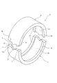
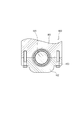
- FIG. 2 is a perspective view showing the split outer ring 2.
- the split outer ring 2 has a first divided outer ring member 5 and a second divided outer ring member 6 formed in a substantially semi-cylindrical shape, and each of the pair of divided outer ring members 5 and 6 has a circumferential direction.
- a cylindrical outer ring is formed by abutting the end portions 5a and 6a with each other.
- flanges 2b projecting in the radial direction with respect to the raceway surface 2a are formed along the circumferential direction.
- the flange 2b regulates the movement of the cylindrical rollers 3 that are a plurality of rolling elements disposed on the raceway surface 2a in the axial direction.
- the end portion 5a as one end portion of the first split outer ring member 5 has a pair of first plane portions 7 extending in parallel to the axis from both ends in the axial direction toward the center, and the pair of first planes.
- a V-shaped recess 8 that is recessed in the circumferential direction with respect to the first flat surface portion 7 is formed between the portions 7.
- the end portion 6a of the second split outer ring member 6 as the other end portion butted against the end portion 5a includes a pair of second plane portions 9 extending in parallel to the axis from both ends in the axial direction, and the pair.
- a convex portion 10 formed between the second flat surface portions 9 and protruding in the circumferential direction and introduced into the concave portion 8 of the first split outer ring member 5 is formed.
- the pair of first plane portions 7 and the pair of second plane portions 9 are in contact with each other with both end portions 5a and 6a butting each other.
- the convex part 10 is formed in the shape (mountain shape) corresponding to the recessed part 8 of the 1st division
- the first divided outer ring member 5 and the second divided outer ring member 6 are axially arranged. Prevents deviation.
- FIG. 3 is an enlarged view of a main part of the split outer ring 2, (a) is a front view of a portion where both end portions 5 a and 6 a are butted together, and (b) is a view in FIG. It is a sectional view taken along line bb.
- the two flat surface portions 7 and 9 of the two divided outer ring members 5 and 6 are in contact with each other as described above.
- the concave portion 8 of the first split outer ring member 5 is formed in a V shape by a pair of inclined wall surfaces 8a that are linearly inclined from the first flat surface portion 7 in a direction recessed in the circumferential direction.
- the portion where the inclined wall surfaces 8 a intersect with each other is the bottom 8 b of the recess 8.
- the convex portion 10 of the second split outer ring member 6 is formed in a mountain shape by a pair of inclined side surfaces 10a that are inclined linearly in a direction protruding in the circumferential direction from the second flat surface portion 9.
- a portion where the pair of inclined side surfaces 10 a intersect with each other is a top portion 10 b of the convex portion 10.
- the concave portion 8 and the convex portion 10 are provided substantially at the center in the axial direction and are formed so as to be symmetric with respect to the center in the axial direction.
- the apex angle ⁇ of the convex portion 10 that is an angle formed by the pair of inclined side surfaces 10a is larger than the inner angle ⁇ of the concave portion 8 that is an angle formed by the pair of inclined wall surfaces 8a. Is set. In this way, by setting the apex angle ⁇ and the inner angle ⁇ , a gap S is formed between the convex portion 10 and the concave portion 8 as shown in FIG. The gap S is formed over almost the entire area between the convex portion 10 and the concave portion 8 including the space between the bottom portion 8 b of the concave portion 8 and the top portion 10 b of the convex portion 10, and the top portion of the convex portion 10.
- the gap S gradually decreases as the base end portion of the convex portion 10 is approached, and the convex portion 10 and the concave portion 8 are in contact with each other in the vicinity of the base end portion of the convex portion 10. In the present embodiment, the vicinity of the base end portion of the convex portion 10 is in contact with the concave portion 8, thereby preventing the two divided outer ring members 5 and 6 from being displaced in the axial direction.
- the gap S is preferably set to about 60 ⁇ m at the maximum. This is because if it is set to be larger than that, it is difficult to effectively prevent the split outer ring members 5 and 6 from shifting in the axial direction.
- curved surfaces are formed on the inner peripheral sides of the end portions 5a and 6a of the split outer ring members 5 and 6 so as to taper toward the distal end edges in the circumferential direction of the end portions 5a and 6a.
- Portions 5b and 6b are formed.
- These curved surface portions 5b and 6b constitute a relief groove 2c that is recessed radially outward with respect to the locus of the raceway surface 2a when both end portions 5a and 6a are butted against each other to form the split outer ring 2.
- the escape groove 2c is provided over the entire axial direction of the raceway surface 2a.
- the cross-sectional shape of the relief groove 2c is a concave curved surface having a predetermined R dimension centered on a radial line passing through the boundary between both ends 5a and 6a, and is set to be positioned in a predetermined circumferential range L.
- the range L is set so that the inner peripheral side of the concave portion 8 and the convex portion 10 becomes a part of the escape groove 2c.
- the escape groove 2c is provided over the entire boundary between both end portions 5a and 6a including the boundary between the concave portion 8 and the convex portion 10, whereby the cylindrical roller 3 that rolls and passes through the escape groove 2c.
- the contact surface pressure from the raceway surface 2a and the outer peripheral surface P1 of the crank pin P can be lowered. As a result, it is possible to effectively prevent the occurrence of vibration or the like that occurs when the cylindrical roller 3 passes through the boundary between the both end portions 5a and 6a.
- the concave portion 8 is formed between the bottom portion 8b of the convex portion 10 and the top portion 10b of the convex portion 10 so as to avoid contact between the top portion 10b and the bottom portion 8b. It is possible to prevent the bottom portion 8b from being pressed directly against the bottom portion 8b. Furthermore, since the stress can be borne by the first and second flat portions 7 and 9 that are in contact with each other, it is possible to prevent the stress from being excessively concentrated on the bottom portion 8b of the recess 8.
- the top portion 10b of the convex portion 10 presses the bottom portion 8b of the concave portion 8 while preventing stress from being excessively concentrated on the bottom portion 8b of the concave portion 8.
- the first split outer ring member 5 it is possible to prevent the first split outer ring member 5 from being cracked along the circumferential direction starting from the bottom 8b.
- the convex part 10 is formed in the value whose apex angle (alpha) is larger than the internal angle (beta) of the recessed part 8, Therefore Between the bottom part 8b of the recessed part 8 and the top part 10b of the convex part 10 only. Instead, the gap S can be provided over almost the entire area between the concave portion 8 and the convex portion 10. Thereby, the excessive stress concentration to the recessed part 8 can be prevented more effectively.
- the split roller bearing 1 of the present embodiment can prevent the first split outer ring member 5 from cracking by using the split outer ring 2 described above. As a result, it is possible to prevent the durability of the split roller bearing 1 from being lowered.
- FIG. 4 is an enlarged view of a main part of the split roller bearing 1 according to the second embodiment of the present invention, and shows a portion where both end portions 5a and 6a of both split outer ring members 5 and 6 are abutted.
- the main difference between this embodiment and said 1st embodiment is that the clearance gap S is formed by making the top part 10b of the convex part 10 into a curved surface.
- the inner angle ⁇ of the concave portion 8 and the apex angle ⁇ of the convex portion 10 are set to substantially the same value, and the inclined wall surface 8a of the concave portion 8 and the inclined side surface 10a of the convex portion 10 are in contact with each other.
- the top portion 10 b of the convex portion 10 is curved as described above, and a gap S is formed between the bottom portion 8 b of the concave portion 8 and the top portion 10 b of the convex portion 10. Also in the case of the present embodiment, the gap S can prevent the top portion 10b of the convex portion 10 from directly contacting and pressing the bottom portion 8b of the concave portion 8.
- the clearance gap S can be provided between the bottom part 8b and the top part 10b by the simple method of making the top part 10b of the convex part 10 into a curved surface, and it is advantageous in terms of cost.
- FIG. 5 is an enlarged view of a main part of the split roller bearing 1 according to the third embodiment of the present invention, and shows a portion where both end portions 5a and 6a of both split outer ring members 5 and 6 are abutted.
- the difference between the present embodiment and each of the above embodiments is that the gap S is formed by the thin portion 11 provided on the bottom portion 8 b of the recess 8.
- the shading portion 11 is formed to be recessed from the inclined wall surface 8a of the concave portion 8 in the circumferential direction, and a gap S is formed with the top portion 10b of the convex portion 10.
- the inside portion 11 is formed with a smooth curved surface, and prevents stress from being concentrated on a part as much as possible.
- the gap S can be provided between the bottom portion 8b and the top portion 10b by a simple method such as forming the thinning portion 11 in the bottom portion 8b of the recess 8, and the cost is the same as in the second embodiment. Is advantageous.
- the present invention is not limited to the above embodiments.
- the pair of inclined wall surfaces 8a constituting the concave portion 8 and the pair of inclined side surfaces 10a constituting the convex portion 10 are each formed to be inclined linearly.
- the concave portion 8 and the convex portion 10 as a whole only have to be formed in a substantially V shape and a substantially mountain shape, respectively.
- Those formed by convexly curving the inclined side surface 10a and those concavely curved conversely include V shapes and mountain shapes.
- tilt angle of the inclination wall surface 8a and the inclination side surface 10a can also be changed in an intermediate part.
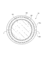
- FIG. 7 is an explanatory cross-sectional view of a rolling bearing 101 according to a fourth embodiment of the present invention
- FIG. 8 is an enlarged explanatory view of the vicinity of the mating surface of the rolling bearing 101 shown in FIG.
- the rolling bearing 101 is formed in a semi-cylindrical shape, and is divided into two in the circumferential direction, and two pairs of split outer rings (outer ring members) that are formed into a cylindrical shape by abutting both ends in the circumferential direction.
- the cage 104 is provided with a split portion at one place in the circumferential direction, and the cage 104 can be assembled by expanding the diameter of the split portion when assembled into the shaft 105. However, it is good also as a split type which provided the split part in two places of the circumferential direction.
- the shaft 105 is fitted into the rolling bearing 101 by being supported by the plurality of rollers 103.
- the shaft 105 also functions as an inner ring.
- a mating surface C is constituted by the circumferential end surface of the split outer ring member 102a and the circumferential end surface of the split outer ring member 102b facing the end surface.
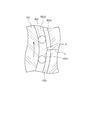
- a curved surface B as a flank is formed on the inner diameter side edge of each end surface of the split outer ring member 102a, 102b constituting the mating surface C.
- the cross-sectional shape of the range where the roller 103 rolls and contacts is constituted by a relaxation curve. More specifically, as shown in FIG.
- the circumferential direction is a boundary between the raceway surfaces 102a1 and 102b1 of the split outer ring members 102a and 102b and the curved surface B from the mating surface C.
- the range L reaches the junction point J.
- the cross-sectional shape of the curved surface in the range h from the raceway surfaces 102a1 and 102b1 to the radially outward direction is constituted by a relaxation curve.
- the size of L can be appropriately selected according to the inner diameter of the raceway surfaces 102a1 and 102b1 of the split outer ring members 102a and 102b and the diameter of the rollers 103. Is also selected within a small range.
- the size of h differs depending on the radial displacement (step) in the mating surface C of the outer ring member and the diameter of the roller 103, but usually a value larger than the size of the step is selected. If the magnitude of h is set to a value larger than the magnitude of the step, at least a range where the rollers 103 are in contact can be a relaxation curve.
- the curved surface B the curved surface other than the contact range of the roller 103 may be an arcuate curved surface, or a curved surface whose cross-sectional shape is a relaxation curve.
- a surface composed of a curved surface in which the cross-sectional shape of the present invention is a relaxation curve and an inclined plane following the outer diameter side (housing side) of the curved surface may be employed.
- the change in the speed vector of the roller 103 at the junction point J can be reduced, and the occurrence of vibration and noise due to the rapid change in the speed vector can be suppressed. be able to.
- a typical clothoid curve (Cornu spiral) can be preferably used, but a cubic parabola that approximates the clothoid curve can also be used.
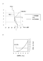
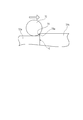
- FIGS. 9A and 9B are diagrams for explaining inclinations of various escape portions with respect to the outer ring raceway.
- FIG. 9A shows cross-sectional shapes of various relief portions
- FIG. 9B shows inclinations of various escape portions with respect to the outer ring raceway.
- the diameter of the outer ring is 60 mm
- the coordinate angle of the relief portion is 5 deg
- the relief depth is 1 mm.
- the solid line indicates a cubic parabola (relaxation curve)
- the broken line indicates an arc
- the alternate long and short dash line indicates a primary incremental line.
- the gradual increase line from the mating surface C to the junction point J (the movement from the bottom to the top in FIG. 9A and the movement from the right to the left in FIG.
- the large end portion 141 has a body portion 143 that is a first housing portion having a concave portion having a substantially semicircular cross section, and a bolt portion 145 that is a cap portion 144 that is a second housing portion having a concave portion having a substantially semicircular cross section.
- the support hole 146 having a substantially circular cross section is formed by fastening and fixing.
- a split roller bearing 151 is incorporated in a support hole 146 having a substantially circular cross section formed by the main body portion 143 and the cap portion 144.
- This rolling bearing 151 is arranged so that it can roll on each inner side surface of a pair of split outer ring members 152a, 152b and two split outer ring members 152a, 152b that are closely arranged in the support hole 146.
- a roller 153 that is a plurality of rolling elements provided, and a cage 154 that holds the rollers 153 so as to be arranged at substantially equal intervals in the circumferential direction, and the crankshaft 142 is an inner ring member of the rolling bearing 151. Is configured.
- the bearing structure is applied to the large end portion of the connecting rod.
- the upper is a housing that constitutes a part of the crankshaft fixing portion 160. It can also be used as a bearing for supporting a crankshaft disposed in a support hole formed by a block 161 and a lower block 162 which is a housing integrally coupled to the upper block 161.
- reference numeral 163 denotes a fixing bolt for integrally fixing the upper block 161 and the lower block 162, and 164 denotes a support shaft for the crankshaft.
- crankshaft is exemplified as the shaft fitted into the bearing.
- bearing structure of the present invention can be applied to other shafts such as a camshaft.
- embodiment mentioned above is provided with the needle bearing which used the roller as a rolling element, the ball bearing which used the ball as a rolling element can also be employ
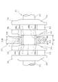
- FIG. 12 is a front sectional view of a rolling bearing according to the fifth embodiment of the present invention.
- the rolling bearing 201 of the present embodiment is attached to the outer peripheral surface of the journal portion 212 of the crankshaft 211 and is fitted in a support hole 213A of a housing 213 provided in the crankcase.
- the housing 213 includes an upper block 213B and a lower block 213C, and the lower block 213C is bolted to the lower surface of the upper block 213B, thereby forming a support hole 213A between the two 213B and 213C.
- the crankshaft 211 includes a journal portion 212, a crank arm 214, a crankpin 215, a balance weight 216, and the like.
- the journal portion 212 is disposed at the rotation center position of the crankshaft 211 and is rotatably supported by the housing 213 via the rolling bearing 201.
- a plurality of crank arms 214 are arranged side by side at intervals in the axial direction, and are connected to each other by a journal portion 212 and a crank pin 215.
- the crank pin 215 is provided at the front end portion of the crank arm 214, and the balance weight 216 is provided at the rear end portion of the crank arm 214.
- the balance weight 216 may be formed integrally with the crank arm 214, or may be formed separately from the crank arm 214.
- FIG. 13 is a side view of the rolling bearing 201.
- the rolling bearing 201 is arranged so that it can roll on the inner peripheral surfaces of two sets of split outer rings (outer ring members) 202a, 202b and two split outer ring members 202a, 202b that are divided in two in the circumferential direction. And a pair of split cages 204a and 204b that hold the rollers 203 so as to be arranged at substantially equal intervals in the circumferential direction.
- the rolling bearing 201 according to the present embodiment includes a pair of two split inner rings (inner ring members) 205a and 205b that are divided into two in the circumferential direction, and the inner peripheral surfaces of the two split inner ring members 205a and 205b are journal portions.
- a roller 203 is disposed so as to be fitted to the outer peripheral surface of 212 and roll on the outer peripheral surfaces of the two split inner ring members 205a and 205b.
- the cage is not limited to the split structure, but has a ring structure that is divided at one place in the circumferential direction, and the divided part is expanded and attached to the outer peripheral side of the split inner ring members 205a and 205b. Also good.
- FIG. 14 is an exploded perspective view of the split inner ring member 205a, 205b.
- the split inner ring members 205a and 205b are made of bearing steel such as SUJ2, and have desired performance such as hardness (for example, HRC58 or higher), mechanical strength, wear resistance, etc. as the raceway of the rolling bearing 201.
- the two split inner ring members 205a and 205b are each formed in a semicircular arc shape, and both end surfaces in the circumferential direction are divided surfaces 205a2 and 205b2 extending straight along the axial direction.
- the two split inner ring members 205a and 205b are abutted with each other on the dividing surfaces 205a2 and 205b2 at both ends in the circumferential direction, or face each other with a slight gap in the circumferential direction.
- the inner peripheral diameters of the two split inner ring members 205 a and 205 b are set to be substantially the same as the outer diameter of the journal part 212, and the inner diameters of the two split inner ring members 205 a and 205 b are formed on the outer peripheral surface of the journal part 212. It is comprised so that a surrounding surface may closely_contact
- the axial length of the split inner ring members 205a and 205b is set slightly larger than the axial interval W between the crank arms 214 arranged on both sides in the axial direction of the journal portion 212, and there is a predetermined distance between the two dimensions. The tightening margin is set.
- the split inner ring members 205a and 205b are attached to the outer peripheral surface of the journal portion 212 by cold fitting or shrink fitting. That is, the split inner ring members 205a and 205b are fitted to the outer peripheral surface of the journal part 212 in a state where the axial dimension is reduced by being cooled, or by heating the journal part 212, the crank arm 214 is heated.
- the journal portion 212 is fitted to the outer peripheral surface in a state where the interval W is widened.
- the rolling bearing 201 of the present embodiment can be firmly attached and fixed to the journal portion 212 even though the inner ring members 205a and 205b have a split structure, and the creep of the split inner ring members 205a and 205b with respect to the journal portion 212 is achieved. Can be prevented.
- a large number of narrow grooves 218 extending along the axial direction are formed on the inner peripheral surfaces of the split inner ring members 205a and 205b at intervals in the circumferential direction. The resistance in the circumferential direction of both split inner ring members 205a and 205b with respect to the portion 212 is increased, and creeping of the split inner ring members 205a and 205b is prevented.
- the roller 203 does not roll on the outer peripheral surface of the journal portion 212, and the journal portion 212 is worn. Damage can be prevented. Further, even when the rolling bearing 201 itself has reached the end of its life, the journal portion 212 hardly undergoes wear or the like, and can be handled by replacing the rolling bearing 201.
- the split inner ring members 205a and 205b are held by the crank arm 214, so that it is not necessary to attach fasteners such as bolts to the split inner ring members 205a and 205b. Therefore, the structure of the split inner ring member 205a, 205b itself can be simplified, and the thickness of the split inner ring member 205a, 205b can be reduced. Therefore, the diameter of the roller 203 is increased accordingly. The life of the rolling bearing 201 can be improved.
- FIG. 15 is an exploded perspective view showing another embodiment of the split inner ring.
- one end portion in the circumferential direction of the split inner ring member 205a, 205b protrudes in the circumferential direction on one axial side, and the other end portion in the circumferential direction projects in the circumferential direction on the opposite side in the axial direction. It has become. Therefore, the split surfaces at both ends in the circumferential direction of the split inner ring members 205a and 205b are split surfaces 205a2 and 205b2 extending along the axial direction, and split surfaces 205a3 extending along the circumferential direction (direction perpendicular to the axial direction). , 205b3, and these are arranged in a substantially Z shape (crank shape).
- the circumferential end portion of one split inner ring member 205a and the circumferential end portion of the other split inner ring member 205b are engaged with each other in the circumferential direction, thereby extending along the circumferential direction.
- the split surfaces 205a3 and 205b3 extending in surface contact with each other. Therefore, when the axial end surfaces 205a1 and 205b1 of the split inner ring members 205a and 205b are clamped by the crank arm 214, the split surfaces 205a3 and 205b3 extending along the circumferential direction of the two split inner ring members 205a and 205b are axially aligned.
- the two split inner ring members 205a and 205b are firmly fixed to each other by the friction force. Therefore, in this embodiment, the split inner ring members 205a and 205b can be attached to the journal portion 212 more firmly than in the fourth embodiment.
- FIG. 16 is an exploded perspective view showing still another embodiment of the split inner ring.
- one end portion in the circumferential direction of the split inner ring member 205a, 205b protrudes in the circumferential direction at the axial center portion, and the other end portion in the circumferential direction recedes in the circumferential direction at the axial center portion. It has become. Therefore, the split surfaces at both ends in the circumferential direction of the split inner ring members 205a and 205b include split surfaces 205a2 and 205b2 extending along the axial direction, and split surfaces 205a3 and 205b3 extending along the circumferential direction. It is arranged in a substantially convex shape and a substantially concave shape.
- the circumferential end portion of one split inner ring member 205a and the circumferential end portion of the other split inner ring member 205b are engaged with each other in a circumferential direction so that the circumferential direction end portion
- the split surfaces 205a3 and 205b3 extending along the surface are in surface contact with each other in the axial direction.
- the split surfaces 205a3 and 205b3 extending along the circumferential direction of the two split inner ring members 205a and 205b are axially aligned.
- the two split inner ring members 205a and 205b are firmly fixed to each other by the friction force, and the split inner ring members 205a and 205b can be attached to the journal portion 212 more firmly.
- the present invention is not limited to the embodiment described above, and can be appropriately changed in design.
- the present invention can also be applied to the case where the rolling bearing 201 is attached to the crank pin 215 of the crankshaft 211.
- the split inner ring members 205a and 205b of the rolling bearing 201 are fitted to the outer peripheral surface of the crank pin 215, and the split inner ring members 205a and 205b are clamped and held by the crank arms 214 on both sides in the axial direction of the crank pin 215.
- What is necessary is just to fit the outer peripheral surface of the split outer ring members 202a and 202b of the rolling bearing 1 into the support hole of the large end portion of the connecting rod (not shown).
- the bearing apparatus of embodiment mentioned above is provided with the needle bearing which used the roller as a rolling element, the ball bearing which used the ball as a rolling element can also be employ
Landscapes
- Engineering & Computer Science (AREA)
- General Engineering & Computer Science (AREA)
- Mechanical Engineering (AREA)
- Rolling Contact Bearings (AREA)
Abstract
L'invention concerne une demi-bague extérieure ayant une durée de vie suffisante et étant adaptée pour que le bruit et les vibrations survenant quand des corps de roulement roulent au-dessus de surfaces de joint soient significativement supprimés, et un demi-palier à roulement utilisant la demi-bague extérieure. Une demi-bague extérieure (2) comporte un premier et un second élément de bague extérieure fendue (5, 6) ayant une forme tubulaire circulaire quand les extrémités circonférentielles du premier et du second élément de bague extérieure fendue (5, 6) sont en butée l'une contre l'autre. A une extrémité (5a) des extrémités circonférentielles en butée l'une contre l'autre sont formés une première section plate (7) et un évidement en V encastré de manière circonférentielle (8). Sur une extrémité (6a) en butée contre l'extrémité (5a) sont formées une seconde section plate (9) en contact avec la première section plate (7) et également une protubérance (10) faisant saillie de manière circonférentielle depuis la seconde surface plate (9) et introduite dans l’évidement (8). Un espace (S) pour empêcher le contact entre le fond (8b) de l’évidement (8) et le sommet (10b) de la protubérance (10) est formé entre l’évidement (8) et la protubérance (10).
Priority Applications (3)
| Application Number | Priority Date | Filing Date | Title |
|---|---|---|---|
| US12/736,880 US8894292B2 (en) | 2008-05-19 | 2009-05-18 | Split outer ring, split rolling bearing using the same ring and construction and method of mounting the same rolling bearing |
| CN2009801184315A CN102037252B (zh) | 2008-05-19 | 2009-05-18 | 剖分外圈、使用剖分外圈的剖分滚动轴承和安装滚动轴承的构造及方法 |
| EP09750534.1A EP2278182B1 (fr) | 2008-05-19 | 2009-05-18 | Bague extérieur divisée, roulement divisé et structure de montage d'un roulement divisé |
Applications Claiming Priority (6)
| Application Number | Priority Date | Filing Date | Title |
|---|---|---|---|
| JP2008130839A JP2009281397A (ja) | 2008-05-19 | 2008-05-19 | 二つ割り外輪、及びこれを用いた二つ割り軸受 |
| JP2008-130839 | 2008-05-19 | ||
| JP2008-236424 | 2008-09-16 | ||
| JP2008236424A JP5417777B2 (ja) | 2008-09-16 | 2008-09-16 | 二つ割り転がり軸受およびこれを備えた軸受構造 |
| JP2008-292292 | 2008-11-14 | ||
| JP2008292292A JP5332529B2 (ja) | 2008-11-14 | 2008-11-14 | 転がり軸受の取付構造及び方法 |
Publications (1)
| Publication Number | Publication Date |
|---|---|
| WO2009142172A1 true WO2009142172A1 (fr) | 2009-11-26 |
Family
ID=41340105
Family Applications (1)
| Application Number | Title | Priority Date | Filing Date |
|---|---|---|---|
| PCT/JP2009/059129 WO2009142172A1 (fr) | 2008-05-19 | 2009-05-18 | Demi-bague extérieure, demi-palier à roulement utilisant celle-ci, et structure et procédé de montage d'un palier à roulement |
Country Status (4)
| Country | Link |
|---|---|
| US (1) | US8894292B2 (fr) |
| EP (2) | EP2278182B1 (fr) |
| CN (1) | CN102037252B (fr) |
| WO (1) | WO2009142172A1 (fr) |
Cited By (2)
| Publication number | Priority date | Publication date | Assignee | Title |
|---|---|---|---|---|
| JP2011247345A (ja) * | 2010-05-26 | 2011-12-08 | Jtekt Corp | クランク軸受装置 |
| CN108999885A (zh) * | 2018-07-20 | 2018-12-14 | 西安理工大学 | 一种半环联接式精密滚动轴承 |
Families Citing this family (17)
| Publication number | Priority date | Publication date | Assignee | Title |
|---|---|---|---|---|
| US8136998B2 (en) * | 2007-12-13 | 2012-03-20 | Jtekt Corporation | Bearing apparatus |
| EP2407679B1 (fr) * | 2009-03-11 | 2015-04-08 | NTN Corporation | Chemin de roulement extérieur divisé en deux, palier à rouleaux et agencement de palier d'arbre rotatif |
| DE102011003419A1 (de) * | 2011-02-01 | 2012-08-02 | Schaeffler Technologies Gmbh & Co. Kg | Ringförmiger Wälzlagerkäfig |
| WO2012115201A1 (fr) * | 2011-02-25 | 2012-08-30 | 日本精工株式会社 | Bague de roulement fendue et son procédé de fabrication |
| CN103089797A (zh) * | 2011-11-01 | 2013-05-08 | 杨嘉明 | 梳齿瓦楔合滚动轴承 |
| JP5938271B2 (ja) | 2012-05-21 | 2016-06-22 | Ntn株式会社 | ころ軸受、およびシャフト支持構造 |
| JP5897625B2 (ja) * | 2014-03-14 | 2016-03-30 | 大同メタル工業株式会社 | すべり軸受 |
| US10975967B2 (en) | 2016-09-16 | 2021-04-13 | Flowserve Management Company | Radially and axially self-aligning split seal ring |
| US10458185B2 (en) | 2017-01-05 | 2019-10-29 | Baker Hughes, A Ge Company, Llc | Mud motors with thrust bearing with enhanced torque |
| EP3568620B1 (fr) | 2017-01-12 | 2021-05-05 | Flowserve Management Company | Mécanisme d'assemblage de bagues d'étanchéité fendues |
| AT520205B1 (de) * | 2017-09-15 | 2019-02-15 | Miba Sinter Austria Gmbh | Lagerdeckel |
| GB2572940A (en) * | 2018-02-27 | 2019-10-23 | Cooper Roller Bearings Company Ltd | Double row spherical roller bearing |
| CN109944873A (zh) * | 2019-04-26 | 2019-06-28 | 西北工业大学 | 一种可双向承载的滚柱轴承 |
| WO2021092372A1 (fr) * | 2019-11-08 | 2021-05-14 | Saint-Gobain Performance Plastics Corporation | Palier fendu, assemblage, et procédé de fabrication et d'utilisation dudit palier |
| CN111779765A (zh) * | 2020-05-19 | 2020-10-16 | 上海涟屹轴承科技有限公司 | 一种舰船变速箱用径向轴承结构 |
| CN114576008A (zh) * | 2020-11-30 | 2022-06-03 | 中国航发商用航空发动机有限责任公司 | 航空发动机机匣和航空发动机 |
| CN115013430A (zh) * | 2022-06-17 | 2022-09-06 | 张振寰 | 断开式滚动轴承 |
Citations (8)
| Publication number | Priority date | Publication date | Assignee | Title |
|---|---|---|---|---|
| JPS55149418A (en) * | 1979-04-28 | 1980-11-20 | Nachi Fujikoshi Corp | Split roller bearing |
| JP2005090696A (ja) | 2003-09-19 | 2005-04-07 | Nsk Ltd | ころ軸受及び内燃機関 |
| JP2006125606A (ja) | 2004-11-01 | 2006-05-18 | Nsk Ltd | ラジアルニードル軸受 |
| JP2006322580A (ja) * | 2005-05-20 | 2006-11-30 | Jtekt Corp | 二つ割り軸受用軌道輪およびこれを備えた二つ割り軸受 |
| JP2006336765A (ja) * | 2005-06-02 | 2006-12-14 | Jtekt Corp | ころ軸受 |
| JP2007247828A (ja) | 2006-03-17 | 2007-09-27 | Honda Motor Co Ltd | 一組の等速ジョイントを含む回転駆動力伝達機構 |
| JP2008057740A (ja) * | 2006-09-04 | 2008-03-13 | Ntn Corp | ころ軸受、カムシャフト支持構造および内燃機関 |
| WO2008029714A1 (fr) | 2006-09-04 | 2008-03-13 | Ntn Corporation | Roulement à rouleaux, structure de support d'arbre à cames, et moteur à combustion interne |
Family Cites Families (15)
| Publication number | Priority date | Publication date | Assignee | Title |
|---|---|---|---|---|
| FR501092A (fr) * | 1918-06-12 | 1920-04-01 | Skf Svenska Kullagerfab Ab | Perfectionnements apportés aux paliers à billes pourvus de chemins de roulement en sections |
| FR627699A (fr) | 1925-01-19 | 1927-10-10 | Perfectionnements aux paliers à billes et à rouleaux | |
| US2528987A (en) * | 1940-05-11 | 1950-11-07 | Albett Charles Antony | Ball and roller bearing |
| US2682435A (en) * | 1953-07-17 | 1954-06-29 | Walter G Rien | Split roller bearing assembly |
| GB960625A (en) * | 1961-08-24 | 1964-06-10 | Cooper Roller Bearings Company | Improvements relating to split roller bearings |
| JPS5337262A (en) * | 1976-09-17 | 1978-04-06 | Ntn Toyo Bearing Co Ltd | Manufacturing method of split bearing ring |
| US7311447B2 (en) * | 2003-09-19 | 2007-12-25 | Nsk Ltd. | Roller bearing |
| JP4438511B2 (ja) | 2004-05-26 | 2010-03-24 | 株式会社ジェイテクト | 二つ割り外輪、それを用いた二つ割りころ軸受 |
| JP2007002914A (ja) * | 2005-06-23 | 2007-01-11 | Nsk Ltd | 軌道輪分割形転がり軸受 |
| JP4790341B2 (ja) * | 2005-07-26 | 2011-10-12 | Ntn株式会社 | 針状ころ軸受および軸受構造 |
| WO2007013317A1 (fr) | 2005-07-29 | 2007-02-01 | Ntn Corporation | Palier a roulements a aiguilles |
| JP2007143045A (ja) * | 2005-11-22 | 2007-06-07 | Toshiba Corp | 画像形成装置と画像形成方法 |
| JP2008095723A (ja) * | 2006-10-06 | 2008-04-24 | Nsk Ltd | 転がり軸受 |
| EP2549132B1 (fr) * | 2007-03-02 | 2015-08-05 | JTEKT Corporation | Appareil de roulement à rouleaux |
| US8136998B2 (en) * | 2007-12-13 | 2012-03-20 | Jtekt Corporation | Bearing apparatus |
-
2009
- 2009-05-18 EP EP09750534.1A patent/EP2278182B1/fr not_active Not-in-force
- 2009-05-18 EP EP14178162.5A patent/EP2801728B1/fr not_active Not-in-force
- 2009-05-18 WO PCT/JP2009/059129 patent/WO2009142172A1/fr active Application Filing
- 2009-05-18 CN CN2009801184315A patent/CN102037252B/zh not_active Expired - Fee Related
- 2009-05-18 US US12/736,880 patent/US8894292B2/en not_active Expired - Fee Related
Patent Citations (8)
| Publication number | Priority date | Publication date | Assignee | Title |
|---|---|---|---|---|
| JPS55149418A (en) * | 1979-04-28 | 1980-11-20 | Nachi Fujikoshi Corp | Split roller bearing |
| JP2005090696A (ja) | 2003-09-19 | 2005-04-07 | Nsk Ltd | ころ軸受及び内燃機関 |
| JP2006125606A (ja) | 2004-11-01 | 2006-05-18 | Nsk Ltd | ラジアルニードル軸受 |
| JP2006322580A (ja) * | 2005-05-20 | 2006-11-30 | Jtekt Corp | 二つ割り軸受用軌道輪およびこれを備えた二つ割り軸受 |
| JP2006336765A (ja) * | 2005-06-02 | 2006-12-14 | Jtekt Corp | ころ軸受 |
| JP2007247828A (ja) | 2006-03-17 | 2007-09-27 | Honda Motor Co Ltd | 一組の等速ジョイントを含む回転駆動力伝達機構 |
| JP2008057740A (ja) * | 2006-09-04 | 2008-03-13 | Ntn Corp | ころ軸受、カムシャフト支持構造および内燃機関 |
| WO2008029714A1 (fr) | 2006-09-04 | 2008-03-13 | Ntn Corporation | Roulement à rouleaux, structure de support d'arbre à cames, et moteur à combustion interne |
Non-Patent Citations (1)
| Title |
|---|
| See also references of EP2278182A4 |
Cited By (2)
| Publication number | Priority date | Publication date | Assignee | Title |
|---|---|---|---|---|
| JP2011247345A (ja) * | 2010-05-26 | 2011-12-08 | Jtekt Corp | クランク軸受装置 |
| CN108999885A (zh) * | 2018-07-20 | 2018-12-14 | 西安理工大学 | 一种半环联接式精密滚动轴承 |
Also Published As
| Publication number | Publication date |
|---|---|
| US8894292B2 (en) | 2014-11-25 |
| EP2801728A2 (fr) | 2014-11-12 |
| CN102037252A (zh) | 2011-04-27 |
| EP2278182A4 (fr) | 2012-07-04 |
| EP2801728B1 (fr) | 2016-08-24 |
| EP2278182B1 (fr) | 2014-09-03 |
| CN102037252B (zh) | 2013-06-26 |
| EP2801728A3 (fr) | 2015-01-07 |
| US20110064350A1 (en) | 2011-03-17 |
| EP2278182A1 (fr) | 2011-01-26 |
Similar Documents
| Publication | Publication Date | Title |
|---|---|---|
| WO2009142172A1 (fr) | Demi-bague extérieure, demi-palier à roulement utilisant celle-ci, et structure et procédé de montage d'un palier à roulement | |
| JP4790341B2 (ja) | 針状ころ軸受および軸受構造 | |
| JP5340697B2 (ja) | 内燃機関用すべり軸受およびすべり軸受装置 | |
| JP5303240B2 (ja) | 転がり軸受および回転軸支持構造 | |
| US8523452B2 (en) | Bearing structure and manufacturing method thereof | |
| JP2009162348A (ja) | 軸受構造 | |
| JP2008095723A (ja) | 転がり軸受 | |
| JP2007139154A (ja) | 針状ころ軸受およびクランクシャフト支持構造 | |
| JP5762698B2 (ja) | 分割型ニードル軸受及び軸受装置 | |
| US10704590B2 (en) | Half thrust bearing | |
| JPH11247845A (ja) | ローラ支持用軸受装置 | |
| JP2005326023A (ja) | ローラ支持用軸受装置 | |
| JP2021167647A (ja) | 転がり軸受 | |
| JP2011252523A (ja) | 転がり軸受装置 | |
| JP5625474B2 (ja) | 二つ割り転がり軸受及びこれを備えた軸受装置 | |
| JPWO2007013317A1 (ja) | 針状ころ軸受 | |
| JP5417777B2 (ja) | 二つ割り転がり軸受およびこれを備えた軸受構造 | |
| JP2006258138A (ja) | 割れ型転がり軸受 | |
| JP5012265B2 (ja) | クランクシャフトの支持構造及びクランクシャフト用軸受 | |
| JP5049044B2 (ja) | 転がり軸受 | |
| JP2007162722A (ja) | クランクシャフト支持構造 | |
| JP2008039055A (ja) | ローラ支持用軸受装置 | |
| JP2009085235A (ja) | 軸受構造 | |
| JP2009019708A (ja) | 分割型針状ころ軸受 | |
| JP2024047719A (ja) | 半割スラスト軸受 |
Legal Events
| Date | Code | Title | Description |
|---|---|---|---|
| WWE | Wipo information: entry into national phase |
Ref document number: 200980118431.5 Country of ref document: CN |
|
| 121 | Ep: the epo has been informed by wipo that ep was designated in this application |
Ref document number: 09750534 Country of ref document: EP Kind code of ref document: A1 |
|
| WWE | Wipo information: entry into national phase |
Ref document number: 2009750534 Country of ref document: EP |
|
| WWE | Wipo information: entry into national phase |
Ref document number: 12736880 Country of ref document: US |
|
| NENP | Non-entry into the national phase |
Ref country code: DE |