WO2009141999A1 - 蓄電デバイス用非水溶媒および蓄電デバイス用非水電解液と、それらを用いた非水系蓄電デバイス、リチウム二次電池および電気二重層キャパシタ - Google Patents
蓄電デバイス用非水溶媒および蓄電デバイス用非水電解液と、それらを用いた非水系蓄電デバイス、リチウム二次電池および電気二重層キャパシタ Download PDFInfo
- Publication number
- WO2009141999A1 WO2009141999A1 PCT/JP2009/002197 JP2009002197W WO2009141999A1 WO 2009141999 A1 WO2009141999 A1 WO 2009141999A1 JP 2009002197 W JP2009002197 W JP 2009002197W WO 2009141999 A1 WO2009141999 A1 WO 2009141999A1
- Authority
- WO
- WIPO (PCT)
- Prior art keywords
- storage device
- solvent
- electricity storage
- nonaqueous
- aqueous
- Prior art date
Links
- 238000003860 storage Methods 0.000 title claims abstract description 128
- 239000003125 aqueous solvent Substances 0.000 title claims abstract description 15
- 239000003990 capacitor Substances 0.000 title claims description 52
- 239000011255 nonaqueous electrolyte Substances 0.000 title claims description 39
- WHXSMMKQMYFTQS-UHFFFAOYSA-N Lithium Chemical compound [Li] WHXSMMKQMYFTQS-UHFFFAOYSA-N 0.000 title description 22
- 229910052744 lithium Inorganic materials 0.000 title description 22
- 229910052731 fluorine Inorganic materials 0.000 claims abstract description 69
- 125000004122 cyclic group Chemical group 0.000 claims abstract description 50
- 229930195734 saturated hydrocarbon Natural products 0.000 claims abstract description 49
- 125000001424 substituent group Chemical group 0.000 claims abstract description 23
- 229910052739 hydrogen Inorganic materials 0.000 claims abstract description 13
- 125000000113 cyclohexyl group Chemical group [H]C1([H])C([H])([H])C([H])([H])C([H])(*)C([H])([H])C1([H])[H] 0.000 claims abstract description 9
- 239000002904 solvent Substances 0.000 claims description 133
- 230000005611 electricity Effects 0.000 claims description 95
- 239000008151 electrolyte solution Substances 0.000 claims description 85
- 239000011737 fluorine Substances 0.000 claims description 55
- YCKRFDGAMUMZLT-UHFFFAOYSA-N Fluorine atom Chemical compound [F] YCKRFDGAMUMZLT-UHFFFAOYSA-N 0.000 claims description 51
- 150000001875 compounds Chemical class 0.000 claims description 42
- -1 sulfone compound Chemical class 0.000 claims description 37
- 150000003839 salts Chemical class 0.000 claims description 35
- HBBGRARXTFLTSG-UHFFFAOYSA-N Lithium ion Chemical compound [Li+] HBBGRARXTFLTSG-UHFFFAOYSA-N 0.000 claims description 26
- 229910001416 lithium ion Inorganic materials 0.000 claims description 26
- 239000003115 supporting electrolyte Substances 0.000 claims description 26
- 150000003457 sulfones Chemical class 0.000 claims description 23
- 150000005676 cyclic carbonates Chemical class 0.000 claims description 12
- 229910003002 lithium salt Inorganic materials 0.000 claims description 6
- 159000000002 lithium salts Chemical group 0.000 claims description 6
- 125000000217 alkyl group Chemical group 0.000 claims description 4
- 125000004432 carbon atom Chemical group C* 0.000 claims description 4
- 150000003242 quaternary ammonium salts Chemical group 0.000 claims description 4
- 125000005587 carbonate group Chemical group 0.000 claims description 3
- 239000010410 layer Substances 0.000 description 70
- RUOJZAUFBMNUDX-UHFFFAOYSA-N propylene carbonate Chemical compound CC1COC(=O)O1 RUOJZAUFBMNUDX-UHFFFAOYSA-N 0.000 description 62
- QXPZOKVSFMRGMQ-UHFFFAOYSA-N trifluoromethylcyclohexane Chemical compound FC(F)(F)C1CCCCC1 QXPZOKVSFMRGMQ-UHFFFAOYSA-N 0.000 description 55
- 239000000203 mixture Substances 0.000 description 51
- 238000007254 oxidation reaction Methods 0.000 description 44
- 230000000052 comparative effect Effects 0.000 description 41
- 230000003647 oxidation Effects 0.000 description 40
- 239000007789 gas Substances 0.000 description 32
- 229910013870 LiPF 6 Inorganic materials 0.000 description 29
- YMWUJEATGCHHMB-UHFFFAOYSA-N Dichloromethane Chemical compound ClCCl YMWUJEATGCHHMB-UHFFFAOYSA-N 0.000 description 28
- 239000003792 electrolyte Substances 0.000 description 22
- 239000012046 mixed solvent Substances 0.000 description 22
- 229940021013 electrolyte solution Drugs 0.000 description 21
- 238000011156 evaluation Methods 0.000 description 21
- 229910052782 aluminium Inorganic materials 0.000 description 19
- 238000007600 charging Methods 0.000 description 19
- XAGFODPZIPBFFR-UHFFFAOYSA-N aluminium Chemical compound [Al] XAGFODPZIPBFFR-UHFFFAOYSA-N 0.000 description 18
- JBTWLSYIZRCDFO-UHFFFAOYSA-N ethyl methyl carbonate Chemical compound CCOC(=O)OC JBTWLSYIZRCDFO-UHFFFAOYSA-N 0.000 description 18
- 125000001153 fluoro group Chemical group F* 0.000 description 18
- UAEPNZWRGJTJPN-UHFFFAOYSA-N methylcyclohexane Chemical compound CC1CCCCC1 UAEPNZWRGJTJPN-UHFFFAOYSA-N 0.000 description 18
- 239000002245 particle Substances 0.000 description 18
- 239000007774 positive electrode material Substances 0.000 description 18
- OKTJSMMVPCPJKN-UHFFFAOYSA-N Carbon Chemical compound [C] OKTJSMMVPCPJKN-UHFFFAOYSA-N 0.000 description 17
- 239000000243 solution Substances 0.000 description 16
- XLYOFNOQVPJJNP-UHFFFAOYSA-N water Substances O XLYOFNOQVPJJNP-UHFFFAOYSA-N 0.000 description 16
- 239000000126 substance Substances 0.000 description 15
- 229910012851 LiCoO 2 Inorganic materials 0.000 description 14
- 230000000694 effects Effects 0.000 description 14
- 239000007788 liquid Substances 0.000 description 14
- 125000004435 hydrogen atom Chemical group [H]* 0.000 description 13
- OIFBSDVPJOWBCH-UHFFFAOYSA-N Diethyl carbonate Chemical compound CCOC(=O)OCC OIFBSDVPJOWBCH-UHFFFAOYSA-N 0.000 description 12
- SECXISVLQFMRJM-UHFFFAOYSA-N N-Methylpyrrolidone Chemical compound CN1CCCC1=O SECXISVLQFMRJM-UHFFFAOYSA-N 0.000 description 12
- 238000002156 mixing Methods 0.000 description 12
- 239000012044 organic layer Substances 0.000 description 12
- DEXFNLNNUZKHNO-UHFFFAOYSA-N 6-[3-[4-[2-(2,3-dihydro-1H-inden-2-ylamino)pyrimidin-5-yl]piperidin-1-yl]-3-oxopropyl]-3H-1,3-benzoxazol-2-one Chemical compound C1C(CC2=CC=CC=C12)NC1=NC=C(C=N1)C1CCN(CC1)C(CCC1=CC2=C(NC(O2)=O)C=C1)=O DEXFNLNNUZKHNO-UHFFFAOYSA-N 0.000 description 11
- 239000011888 foil Substances 0.000 description 11
- 238000004817 gas chromatography Methods 0.000 description 11
- 238000005259 measurement Methods 0.000 description 11
- 238000012360 testing method Methods 0.000 description 11
- HMUNWXXNJPVALC-UHFFFAOYSA-N 1-[4-[2-(2,3-dihydro-1H-inden-2-ylamino)pyrimidin-5-yl]piperazin-1-yl]-2-(2,4,6,7-tetrahydrotriazolo[4,5-c]pyridin-5-yl)ethanone Chemical compound C1C(CC2=CC=CC=C12)NC1=NC=C(C=N1)N1CCN(CC1)C(CN1CC2=C(CC1)NN=N2)=O HMUNWXXNJPVALC-UHFFFAOYSA-N 0.000 description 10
- IEJIGPNLZYLLBP-UHFFFAOYSA-N dimethyl carbonate Chemical compound COC(=O)OC IEJIGPNLZYLLBP-UHFFFAOYSA-N 0.000 description 10
- 238000000034 method Methods 0.000 description 10
- PXHVJJICTQNCMI-UHFFFAOYSA-N nickel Substances [Ni] PXHVJJICTQNCMI-UHFFFAOYSA-N 0.000 description 10
- 229910001220 stainless steel Inorganic materials 0.000 description 10
- XAXBJEMVFBTTKF-UHFFFAOYSA-N 1,2-bis(trifluoromethyl)cyclohexane Chemical compound FC(F)(F)C1CCCCC1C(F)(F)F XAXBJEMVFBTTKF-UHFFFAOYSA-N 0.000 description 9
- RIUQAPDKVUDMLI-UHFFFAOYSA-N 1-fluoroethylcyclohexane Chemical compound CC(F)C1CCCCC1 RIUQAPDKVUDMLI-UHFFFAOYSA-N 0.000 description 9
- HEMHJVSKTPXQMS-UHFFFAOYSA-M Sodium hydroxide Chemical compound [OH-].[Na+] HEMHJVSKTPXQMS-UHFFFAOYSA-M 0.000 description 9
- 229910052799 carbon Inorganic materials 0.000 description 9
- 239000006258 conductive agent Substances 0.000 description 9
- 238000010438 heat treatment Methods 0.000 description 9
- 239000000463 material Substances 0.000 description 9
- GYNNXHKOJHMOHS-UHFFFAOYSA-N methyl-cycloheptane Natural products CC1CCCCCC1 GYNNXHKOJHMOHS-UHFFFAOYSA-N 0.000 description 9
- 238000002360 preparation method Methods 0.000 description 9
- HXJUTPCZVOIRIF-UHFFFAOYSA-N sulfolane Chemical compound O=S1(=O)CCCC1 HXJUTPCZVOIRIF-UHFFFAOYSA-N 0.000 description 9
- 239000002033 PVDF binder Substances 0.000 description 8
- DTQVDTLACAAQTR-UHFFFAOYSA-N Trifluoroacetic acid Chemical compound OC(=O)C(F)(F)F DTQVDTLACAAQTR-UHFFFAOYSA-N 0.000 description 8
- 150000005678 chain carbonates Chemical class 0.000 description 8
- 125000000753 cycloalkyl group Chemical group 0.000 description 8
- 239000012153 distilled water Substances 0.000 description 8
- 239000011521 glass Substances 0.000 description 8
- 150000002430 hydrocarbons Chemical class 0.000 description 8
- 229920002981 polyvinylidene fluoride Polymers 0.000 description 8
- 239000010935 stainless steel Substances 0.000 description 8
- 239000011230 binding agent Substances 0.000 description 7
- 229910052751 metal Inorganic materials 0.000 description 7
- 239000002184 metal Substances 0.000 description 7
- 239000002798 polar solvent Substances 0.000 description 7
- 238000003756 stirring Methods 0.000 description 7
- BRRLJOYGNUNENI-UHFFFAOYSA-N 2-fluoroethylcyclohexane Chemical compound FCCC1CCCCC1 BRRLJOYGNUNENI-UHFFFAOYSA-N 0.000 description 6
- CSNNHWWHGAXBCP-UHFFFAOYSA-L Magnesium sulfate Chemical compound [Mg+2].[O-][S+2]([O-])([O-])[O-] CSNNHWWHGAXBCP-UHFFFAOYSA-L 0.000 description 6
- OKKJLVBELUTLKV-UHFFFAOYSA-N Methanol Chemical compound OC OKKJLVBELUTLKV-UHFFFAOYSA-N 0.000 description 6
- 239000004743 Polypropylene Substances 0.000 description 6
- 230000002238 attenuated effect Effects 0.000 description 6
- 238000010280 constant potential charging Methods 0.000 description 6
- 238000010277 constant-current charging Methods 0.000 description 6
- CSJLBAMHHLJAAS-UHFFFAOYSA-N diethylaminosulfur trifluoride Chemical compound CCN(CC)S(F)(F)F CSJLBAMHHLJAAS-UHFFFAOYSA-N 0.000 description 6
- 239000001257 hydrogen Substances 0.000 description 6
- XLYOFNOQVPJJNP-UHFFFAOYSA-M hydroxide Chemical compound [OH-] XLYOFNOQVPJJNP-UHFFFAOYSA-M 0.000 description 6
- 239000005001 laminate film Substances 0.000 description 6
- 238000000634 powder X-ray diffraction Methods 0.000 description 6
- 239000002244 precipitate Substances 0.000 description 6
- 238000007789 sealing Methods 0.000 description 6
- VTWYQAQIXXAXOR-UHFFFAOYSA-N 2-methylsulfonylpropane Chemical compound CC(C)S(C)(=O)=O VTWYQAQIXXAXOR-UHFFFAOYSA-N 0.000 description 5
- 239000004698 Polyethylene Substances 0.000 description 5
- 239000006230 acetylene black Substances 0.000 description 5
- 239000011149 active material Substances 0.000 description 5
- 238000004519 manufacturing process Methods 0.000 description 5
- 238000006864 oxidative decomposition reaction Methods 0.000 description 5
- 229920000573 polyethylene Polymers 0.000 description 5
- 238000005406 washing Methods 0.000 description 5
- WZFUQSJFWNHZHM-UHFFFAOYSA-N 2-[4-[2-(2,3-dihydro-1H-inden-2-ylamino)pyrimidin-5-yl]piperazin-1-yl]-1-(2,4,6,7-tetrahydrotriazolo[4,5-c]pyridin-5-yl)ethanone Chemical compound C1C(CC2=CC=CC=C12)NC1=NC=C(C=N1)N1CCN(CC1)CC(=O)N1CC2=C(CC1)NN=N2 WZFUQSJFWNHZHM-UHFFFAOYSA-N 0.000 description 4
- CMJLMPKFQPJDKP-UHFFFAOYSA-N 3-methylthiolane 1,1-dioxide Chemical compound CC1CCS(=O)(=O)C1 CMJLMPKFQPJDKP-UHFFFAOYSA-N 0.000 description 4
- IJGRMHOSHXDMSA-UHFFFAOYSA-N Atomic nitrogen Chemical compound N#N IJGRMHOSHXDMSA-UHFFFAOYSA-N 0.000 description 4
- KMTRUDSVKNLOMY-UHFFFAOYSA-N Ethylene carbonate Chemical compound O=C1OCCO1 KMTRUDSVKNLOMY-UHFFFAOYSA-N 0.000 description 4
- UFHFLCQGNIYNRP-UHFFFAOYSA-N Hydrogen Chemical compound [H][H] UFHFLCQGNIYNRP-UHFFFAOYSA-N 0.000 description 4
- OFBQJSOFQDEBGM-UHFFFAOYSA-N Pentane Chemical compound CCCCC OFBQJSOFQDEBGM-UHFFFAOYSA-N 0.000 description 4
- XUIMIQQOPSSXEZ-UHFFFAOYSA-N Silicon Chemical compound [Si] XUIMIQQOPSSXEZ-UHFFFAOYSA-N 0.000 description 4
- ATJFFYVFTNAWJD-UHFFFAOYSA-N Tin Chemical compound [Sn] ATJFFYVFTNAWJD-UHFFFAOYSA-N 0.000 description 4
- QVGXLLKOCUKJST-UHFFFAOYSA-N atomic oxygen Chemical compound [O] QVGXLLKOCUKJST-UHFFFAOYSA-N 0.000 description 4
- 238000004364 calculation method Methods 0.000 description 4
- 238000006243 chemical reaction Methods 0.000 description 4
- 239000011248 coating agent Substances 0.000 description 4
- 238000000576 coating method Methods 0.000 description 4
- 230000007423 decrease Effects 0.000 description 4
- 238000004821 distillation Methods 0.000 description 4
- 238000001914 filtration Methods 0.000 description 4
- 238000004770 highest occupied molecular orbital Methods 0.000 description 4
- 150000002500 ions Chemical class 0.000 description 4
- 238000004502 linear sweep voltammetry Methods 0.000 description 4
- 229910052759 nickel Inorganic materials 0.000 description 4
- 229910052760 oxygen Inorganic materials 0.000 description 4
- 239000001301 oxygen Substances 0.000 description 4
- BASFCYQUMIYNBI-UHFFFAOYSA-N platinum Substances [Pt] BASFCYQUMIYNBI-UHFFFAOYSA-N 0.000 description 4
- 239000000047 product Substances 0.000 description 4
- 239000010703 silicon Substances 0.000 description 4
- 229910052710 silicon Inorganic materials 0.000 description 4
- 238000003466 welding Methods 0.000 description 4
- UEUGALWLUYPXSZ-UHFFFAOYSA-N 2-cyclohexylethyl methanesulfonate Chemical compound CS(=O)(=O)OCCC1CCCCC1 UEUGALWLUYPXSZ-UHFFFAOYSA-N 0.000 description 3
- WEVYAHXRMPXWCK-UHFFFAOYSA-N Acetonitrile Chemical compound CC#N WEVYAHXRMPXWCK-UHFFFAOYSA-N 0.000 description 3
- 238000004438 BET method Methods 0.000 description 3
- BVKZGUZCCUSVTD-UHFFFAOYSA-L Carbonate Chemical compound [O-]C([O-])=O BVKZGUZCCUSVTD-UHFFFAOYSA-L 0.000 description 3
- 229910020599 Co 3 O 4 Inorganic materials 0.000 description 3
- XDTMQSROBMDMFD-UHFFFAOYSA-N Cyclohexane Chemical compound C1CCCCC1 XDTMQSROBMDMFD-UHFFFAOYSA-N 0.000 description 3
- PMZURENOXWZQFD-UHFFFAOYSA-L Sodium Sulfate Chemical compound [Na+].[Na+].[O-]S([O-])(=O)=O PMZURENOXWZQFD-UHFFFAOYSA-L 0.000 description 3
- ZMANZCXQSJIPKH-UHFFFAOYSA-N Triethylamine Chemical compound CCN(CC)CC ZMANZCXQSJIPKH-UHFFFAOYSA-N 0.000 description 3
- 239000012670 alkaline solution Substances 0.000 description 3
- 238000004458 analytical method Methods 0.000 description 3
- 150000001450 anions Chemical class 0.000 description 3
- 239000007864 aqueous solution Substances 0.000 description 3
- 150000001721 carbon Chemical group 0.000 description 3
- 150000004649 carbonic acid derivatives Chemical class 0.000 description 3
- 150000001768 cations Chemical class 0.000 description 3
- 230000008859 change Effects 0.000 description 3
- 229940044175 cobalt sulfate Drugs 0.000 description 3
- 229910000361 cobalt sulfate Inorganic materials 0.000 description 3
- KTVIXTQDYHMGHF-UHFFFAOYSA-L cobalt(2+) sulfate Chemical compound [Co+2].[O-]S([O-])(=O)=O KTVIXTQDYHMGHF-UHFFFAOYSA-L 0.000 description 3
- 238000000354 decomposition reaction Methods 0.000 description 3
- 230000006866 deterioration Effects 0.000 description 3
- 238000007599 discharging Methods 0.000 description 3
- 238000009826 distribution Methods 0.000 description 3
- 238000005868 electrolysis reaction Methods 0.000 description 3
- 238000005516 engineering process Methods 0.000 description 3
- 238000002474 experimental method Methods 0.000 description 3
- 239000000835 fiber Substances 0.000 description 3
- 238000000806 fluorine-19 nuclear magnetic resonance spectrum Methods 0.000 description 3
- XGZVUEUWXADBQD-UHFFFAOYSA-L lithium carbonate Chemical compound [Li+].[Li+].[O-]C([O-])=O XGZVUEUWXADBQD-UHFFFAOYSA-L 0.000 description 3
- 230000007246 mechanism Effects 0.000 description 3
- 229920001155 polypropylene Polymers 0.000 description 3
- 238000000425 proton nuclear magnetic resonance spectrum Methods 0.000 description 3
- 238000010298 pulverizing process Methods 0.000 description 3
- 239000002994 raw material Substances 0.000 description 3
- 229920006395 saturated elastomer Polymers 0.000 description 3
- 125000006850 spacer group Chemical group 0.000 description 3
- 238000001308 synthesis method Methods 0.000 description 3
- IIZKNKHOOPBVEG-UHFFFAOYSA-N 1,1,2,2,2-pentafluoroethylcyclohexane Chemical compound FC(F)(F)C(F)(F)C1CCCCC1 IIZKNKHOOPBVEG-UHFFFAOYSA-N 0.000 description 2
- GBAPQIKKEVNMLC-UHFFFAOYSA-N 1,1-bis(1,1,2,2,2-pentafluoroethyl)cyclohexane Chemical compound FC(F)(F)C(F)(F)C1(C(F)(F)C(F)(F)F)CCCCC1 GBAPQIKKEVNMLC-UHFFFAOYSA-N 0.000 description 2
- SGJDSXRTGWZIMH-UHFFFAOYSA-N 1,1-bis(trifluoromethyl)cyclohexane Chemical compound FC(F)(F)C1(C(F)(F)F)CCCCC1 SGJDSXRTGWZIMH-UHFFFAOYSA-N 0.000 description 2
- XXZOEDQFGXTEAD-UHFFFAOYSA-N 1,2-bis(trifluoromethyl)benzene Chemical compound FC(F)(F)C1=CC=CC=C1C(F)(F)F XXZOEDQFGXTEAD-UHFFFAOYSA-N 0.000 description 2
- ZZXUZKXVROWEIF-UHFFFAOYSA-N 1,2-butylene carbonate Chemical compound CCC1COC(=O)O1 ZZXUZKXVROWEIF-UHFFFAOYSA-N 0.000 description 2
- XIJLJFDFDZSWDG-UHFFFAOYSA-N 1,3-bis(trifluoromethyl)cyclohexane Chemical compound FC(F)(F)C1CCCC(C(F)(F)F)C1 XIJLJFDFDZSWDG-UHFFFAOYSA-N 0.000 description 2
- QJQZRLXDLORINA-UHFFFAOYSA-N 2-cyclohexylethanol Chemical compound OCCC1CCCCC1 QJQZRLXDLORINA-UHFFFAOYSA-N 0.000 description 2
- YLZOPXRUQYQQID-UHFFFAOYSA-N 3-(2,4,6,7-tetrahydrotriazolo[4,5-c]pyridin-5-yl)-1-[4-[2-[[3-(trifluoromethoxy)phenyl]methylamino]pyrimidin-5-yl]piperazin-1-yl]propan-1-one Chemical compound N1N=NC=2CN(CCC=21)CCC(=O)N1CCN(CC1)C=1C=NC(=NC=1)NCC1=CC(=CC=C1)OC(F)(F)F YLZOPXRUQYQQID-UHFFFAOYSA-N 0.000 description 2
- YEJRWHAVMIAJKC-UHFFFAOYSA-N 4-Butyrolactone Chemical compound O=C1CCCO1 YEJRWHAVMIAJKC-UHFFFAOYSA-N 0.000 description 2
- VEXZGXHMUGYJMC-UHFFFAOYSA-N Hydrochloric acid Chemical compound Cl VEXZGXHMUGYJMC-UHFFFAOYSA-N 0.000 description 2
- 229910013063 LiBF 4 Inorganic materials 0.000 description 2
- 229910013684 LiClO 4 Inorganic materials 0.000 description 2
- UIIMBOGNXHQVGW-UHFFFAOYSA-M Sodium bicarbonate Chemical compound [Na+].OC([O-])=O UIIMBOGNXHQVGW-UHFFFAOYSA-M 0.000 description 2
- FAPWRFPIFSIZLT-UHFFFAOYSA-M Sodium chloride Chemical class [Na+].[Cl-] FAPWRFPIFSIZLT-UHFFFAOYSA-M 0.000 description 2
- RTAQQCXQSZGOHL-UHFFFAOYSA-N Titanium Chemical compound [Ti] RTAQQCXQSZGOHL-UHFFFAOYSA-N 0.000 description 2
- 125000004429 atom Chemical group 0.000 description 2
- 229920006026 co-polymeric resin Polymers 0.000 description 2
- 239000004020 conductor Substances 0.000 description 2
- 238000013461 design Methods 0.000 description 2
- 238000009792 diffusion process Methods 0.000 description 2
- 238000004090 dissolution Methods 0.000 description 2
- 238000001035 drying Methods 0.000 description 2
- 229920001971 elastomer Polymers 0.000 description 2
- 239000007772 electrode material Substances 0.000 description 2
- IIEWJVIFRVWJOD-UHFFFAOYSA-N ethyl cyclohexane Natural products CCC1CCCCC1 IIEWJVIFRVWJOD-UHFFFAOYSA-N 0.000 description 2
- 239000000945 filler Substances 0.000 description 2
- HCDGVLDPFQMKDK-UHFFFAOYSA-N hexafluoropropylene Chemical group FC(F)=C(F)C(F)(F)F HCDGVLDPFQMKDK-UHFFFAOYSA-N 0.000 description 2
- 238000002347 injection Methods 0.000 description 2
- 239000007924 injection Substances 0.000 description 2
- KWGKDLIKAYFUFQ-UHFFFAOYSA-M lithium chloride Chemical compound [Li+].[Cl-] KWGKDLIKAYFUFQ-UHFFFAOYSA-M 0.000 description 2
- 229910052749 magnesium Inorganic materials 0.000 description 2
- 239000011777 magnesium Substances 0.000 description 2
- 125000002496 methyl group Chemical group [H]C([H])([H])* 0.000 description 2
- 239000011259 mixed solution Substances 0.000 description 2
- 229910052757 nitrogen Inorganic materials 0.000 description 2
- 239000003960 organic solvent Substances 0.000 description 2
- 238000010525 oxidative degradation reaction Methods 0.000 description 2
- 230000001590 oxidative effect Effects 0.000 description 2
- 229920001343 polytetrafluoroethylene Polymers 0.000 description 2
- 239000004810 polytetrafluoroethylene Substances 0.000 description 2
- 229920000036 polyvinylpyrrolidone Polymers 0.000 description 2
- 239000001267 polyvinylpyrrolidone Substances 0.000 description 2
- 235000013855 polyvinylpyrrolidone Nutrition 0.000 description 2
- 239000000843 powder Substances 0.000 description 2
- 229920005989 resin Polymers 0.000 description 2
- 239000011347 resin Substances 0.000 description 2
- 238000007086 side reaction Methods 0.000 description 2
- 239000002002 slurry Substances 0.000 description 2
- 229910052708 sodium Inorganic materials 0.000 description 2
- 239000011734 sodium Substances 0.000 description 2
- 238000010408 sweeping Methods 0.000 description 2
- FPGGTKZVZWFYPV-UHFFFAOYSA-M tetrabutylammonium fluoride Chemical compound [F-].CCCC[N+](CCCC)(CCCC)CCCC FPGGTKZVZWFYPV-UHFFFAOYSA-M 0.000 description 2
- 238000004809 thin layer chromatography Methods 0.000 description 2
- 229910000314 transition metal oxide Inorganic materials 0.000 description 2
- IDBYQQQHBYGLEQ-UHFFFAOYSA-N 1,1,2,2,3,3,4-heptafluorocyclopentane Chemical compound FC1CC(F)(F)C(F)(F)C1(F)F IDBYQQQHBYGLEQ-UHFFFAOYSA-N 0.000 description 1
- XUMCUOFZBDFOAA-UHFFFAOYSA-N 1,1,2,2-tetrafluoroethylcyclohexane Chemical compound FC(F)C(F)(F)C1CCCCC1 XUMCUOFZBDFOAA-UHFFFAOYSA-N 0.000 description 1
- FPPBYJBOHUMXJN-UHFFFAOYSA-N 1,1,2-trifluorocyclohexane Chemical compound FC1CCCCC1(F)F FPPBYJBOHUMXJN-UHFFFAOYSA-N 0.000 description 1
- PCBXUDQFZHWMKH-UHFFFAOYSA-N 1,1,2-trifluoroethylcyclohexane Chemical compound FCC(F)(F)C1CCCCC1 PCBXUDQFZHWMKH-UHFFFAOYSA-N 0.000 description 1
- DBVMRQUISHFOFA-UHFFFAOYSA-N 1,1-difluoroethylcyclohexane Chemical compound CC(F)(F)C1CCCCC1 DBVMRQUISHFOFA-UHFFFAOYSA-N 0.000 description 1
- BQSOVTVFDGMJNB-UHFFFAOYSA-N 1,2,2,2-tetrafluoroethylcyclohexane Chemical compound FC(F)(F)C(F)C1CCCCC1 BQSOVTVFDGMJNB-UHFFFAOYSA-N 0.000 description 1
- RKURYFJWZRPRGW-UHFFFAOYSA-N 1,2,2-trifluoroethylcyclohexane Chemical compound FC(F)C(F)C1CCCCC1 RKURYFJWZRPRGW-UHFFFAOYSA-N 0.000 description 1
- SZZVRXGIUHCXFW-UHFFFAOYSA-N 1,2-bis(1,1,2,2,2-pentafluoroethyl)cyclohexane Chemical compound FC(F)(F)C(F)(F)C1CCCCC1C(F)(F)C(F)(F)F SZZVRXGIUHCXFW-UHFFFAOYSA-N 0.000 description 1
- FIZHQDJATNUMKC-UHFFFAOYSA-N 1,2-difluoroethylcyclohexane Chemical compound FCC(F)C1CCCCC1 FIZHQDJATNUMKC-UHFFFAOYSA-N 0.000 description 1
- JKSIJLIVHIGTNW-UHFFFAOYSA-N 1,3-bis(1,1,2,2,2-pentafluoroethyl)cyclohexane Chemical compound FC(F)(F)C(F)(F)C1CCCC(C(F)(F)C(F)(F)F)C1 JKSIJLIVHIGTNW-UHFFFAOYSA-N 0.000 description 1
- VAYTZRYEBVHVLE-UHFFFAOYSA-N 1,3-dioxol-2-one Chemical compound O=C1OC=CO1 VAYTZRYEBVHVLE-UHFFFAOYSA-N 0.000 description 1
- QRDOKWVJJZIGMB-UHFFFAOYSA-N 1,4-bis(1,1,2,2,2-pentafluoroethyl)cyclohexane Chemical compound FC(F)(F)C(F)(F)C1CCC(C(F)(F)C(F)(F)F)CC1 QRDOKWVJJZIGMB-UHFFFAOYSA-N 0.000 description 1
- YQBZQARTKCPGBH-UHFFFAOYSA-N 1,4-bis(trifluoromethyl)cyclohexane Chemical compound FC(F)(F)C1CCC(C(F)(F)F)CC1 YQBZQARTKCPGBH-UHFFFAOYSA-N 0.000 description 1
- RCJZROJZUKPMTD-UHFFFAOYSA-N 1-(1,1,2,2,2-pentafluoroethyl)-1-(trifluoromethyl)cyclohexane Chemical compound FC(F)(F)C(F)(F)C1(C(F)(F)F)CCCCC1 RCJZROJZUKPMTD-UHFFFAOYSA-N 0.000 description 1
- JMSUNAQVHOHLMX-UHFFFAOYSA-N 1-cyclohexylethanol Chemical compound CC(O)C1CCCCC1 JMSUNAQVHOHLMX-UHFFFAOYSA-N 0.000 description 1
- KRYBGIIKAMJTRV-UHFFFAOYSA-N 2,2,2-trifluoroethylcyclohexane Chemical compound FC(F)(F)CC1CCCCC1 KRYBGIIKAMJTRV-UHFFFAOYSA-N 0.000 description 1
- CAOLGXLVJKIZKZ-UHFFFAOYSA-N 3-methylthiolane 1,1-dioxide thiolane 1,1-dioxide Chemical compound O=S1(=O)CCCC1.CC1CCS(=O)(=O)C1 CAOLGXLVJKIZKZ-UHFFFAOYSA-N 0.000 description 1
- SBLRHMKNNHXPHG-UHFFFAOYSA-N 4-fluoro-1,3-dioxolan-2-one Chemical compound FC1COC(=O)O1 SBLRHMKNNHXPHG-UHFFFAOYSA-N 0.000 description 1
- VHUUQVKOLVNVRT-UHFFFAOYSA-N Ammonium hydroxide Chemical compound [NH4+].[OH-] VHUUQVKOLVNVRT-UHFFFAOYSA-N 0.000 description 1
- 229920000049 Carbon (fiber) Polymers 0.000 description 1
- 229910018871 CoO 2 Inorganic materials 0.000 description 1
- RYGMFSIKBFXOCR-UHFFFAOYSA-N Copper Chemical compound [Cu] RYGMFSIKBFXOCR-UHFFFAOYSA-N 0.000 description 1
- 238000004057 DFT-B3LYP calculation Methods 0.000 description 1
- YZCKVEUIGOORGS-OUBTZVSYSA-N Deuterium Chemical group [2H] YZCKVEUIGOORGS-OUBTZVSYSA-N 0.000 description 1
- XJCNIFKXBRJJEN-UHFFFAOYSA-N FCCC1CCCCC1.FCCC1CCCCC1 Chemical compound FCCC1CCCCC1.FCCC1CCCCC1 XJCNIFKXBRJJEN-UHFFFAOYSA-N 0.000 description 1
- DGAQECJNVWCQMB-PUAWFVPOSA-M Ilexoside XXIX Chemical compound C[C@@H]1CC[C@@]2(CC[C@@]3(C(=CC[C@H]4[C@]3(CC[C@@H]5[C@@]4(CC[C@@H](C5(C)C)OS(=O)(=O)[O-])C)C)[C@@H]2[C@]1(C)O)C)C(=O)O[C@H]6[C@@H]([C@H]([C@@H]([C@H](O6)CO)O)O)O.[Na+] DGAQECJNVWCQMB-PUAWFVPOSA-M 0.000 description 1
- 229910015015 LiAsF 6 Inorganic materials 0.000 description 1
- 229910012513 LiSbF 6 Inorganic materials 0.000 description 1
- FYYHWMGAXLPEAU-UHFFFAOYSA-N Magnesium Chemical compound [Mg] FYYHWMGAXLPEAU-UHFFFAOYSA-N 0.000 description 1
- 239000012359 Methanesulfonyl chloride Substances 0.000 description 1
- ZLMJMSJWJFRBEC-UHFFFAOYSA-N Potassium Chemical compound [K] ZLMJMSJWJFRBEC-UHFFFAOYSA-N 0.000 description 1
- 229910000676 Si alloy Inorganic materials 0.000 description 1
- 229910001128 Sn alloy Inorganic materials 0.000 description 1
- 229920002125 Sokalan® Polymers 0.000 description 1
- 239000004809 Teflon Substances 0.000 description 1
- 229920006362 Teflon® Polymers 0.000 description 1
- YZCKVEUIGOORGS-NJFSPNSNSA-N Tritium Chemical group [3H] YZCKVEUIGOORGS-NJFSPNSNSA-N 0.000 description 1
- FHKPLLOSJHHKNU-INIZCTEOSA-N [(3S)-3-[8-(1-ethyl-5-methylpyrazol-4-yl)-9-methylpurin-6-yl]oxypyrrolidin-1-yl]-(oxan-4-yl)methanone Chemical compound C(C)N1N=CC(=C1C)C=1N(C2=NC=NC(=C2N=1)O[C@@H]1CN(CC1)C(=O)C1CCOCC1)C FHKPLLOSJHHKNU-INIZCTEOSA-N 0.000 description 1
- 239000002253 acid Substances 0.000 description 1
- 239000000654 additive Substances 0.000 description 1
- 229910052783 alkali metal Inorganic materials 0.000 description 1
- 229910052784 alkaline earth metal Inorganic materials 0.000 description 1
- 239000000956 alloy Substances 0.000 description 1
- QGZKDVFQNNGYKY-UHFFFAOYSA-N ammonia Natural products N QGZKDVFQNNGYKY-UHFFFAOYSA-N 0.000 description 1
- 229910052787 antimony Inorganic materials 0.000 description 1
- 229910052796 boron Inorganic materials 0.000 description 1
- 239000006229 carbon black Substances 0.000 description 1
- 235000019241 carbon black Nutrition 0.000 description 1
- 239000004917 carbon fiber Substances 0.000 description 1
- 239000003575 carbonaceous material Substances 0.000 description 1
- BCZZCSPWPQMEQS-UHFFFAOYSA-N carbonic acid hydrofluoride Chemical class C(O)(O)=O.F BCZZCSPWPQMEQS-UHFFFAOYSA-N 0.000 description 1
- 229910052804 chromium Inorganic materials 0.000 description 1
- 239000013065 commercial product Substances 0.000 description 1
- 239000002131 composite material Substances 0.000 description 1
- 238000007796 conventional method Methods 0.000 description 1
- 229910052802 copper Inorganic materials 0.000 description 1
- 239000010949 copper Substances 0.000 description 1
- 239000011889 copper foil Substances 0.000 description 1
- 238000010908 decantation Methods 0.000 description 1
- 238000011161 development Methods 0.000 description 1
- JOCDQQMYNFSIRO-UHFFFAOYSA-N difluoromethylcyclohexane Chemical compound FC(F)C1CCCCC1 JOCDQQMYNFSIRO-UHFFFAOYSA-N 0.000 description 1
- 238000007865 diluting Methods 0.000 description 1
- VUPKGFBOKBGHFZ-UHFFFAOYSA-N dipropyl carbonate Chemical compound CCCOC(=O)OCCC VUPKGFBOKBGHFZ-UHFFFAOYSA-N 0.000 description 1
- 239000002270 dispersing agent Substances 0.000 description 1
- 239000011532 electronic conductor Substances 0.000 description 1
- 239000003623 enhancer Substances 0.000 description 1
- 238000000605 extraction Methods 0.000 description 1
- 239000002657 fibrous material Substances 0.000 description 1
- 238000003682 fluorination reaction Methods 0.000 description 1
- 150000002221 fluorine Chemical class 0.000 description 1
- BZFJSPDOVDCIMD-UHFFFAOYSA-N fluoromethylcyclohexane Chemical compound FCC1CCCCC1 BZFJSPDOVDCIMD-UHFFFAOYSA-N 0.000 description 1
- 125000000524 functional group Chemical group 0.000 description 1
- 229910021469 graphitizable carbon Inorganic materials 0.000 description 1
- 230000006872 improvement Effects 0.000 description 1
- 239000011261 inert gas Substances 0.000 description 1
- 238000003780 insertion Methods 0.000 description 1
- 230000037431 insertion Effects 0.000 description 1
- 230000003993 interaction Effects 0.000 description 1
- 239000010416 ion conductor Substances 0.000 description 1
- 229910052742 iron Inorganic materials 0.000 description 1
- 125000001449 isopropyl group Chemical group [H]C([H])([H])C([H])(*)C([H])([H])[H] 0.000 description 1
- 229910052745 lead Inorganic materials 0.000 description 1
- 230000007257 malfunction Effects 0.000 description 1
- 229910052748 manganese Inorganic materials 0.000 description 1
- 238000002844 melting Methods 0.000 description 1
- 230000008018 melting Effects 0.000 description 1
- 229910044991 metal oxide Inorganic materials 0.000 description 1
- 150000004706 metal oxides Chemical class 0.000 description 1
- QARBMVPHQWIHKH-UHFFFAOYSA-N methanesulfonyl chloride Chemical compound CS(Cl)(=O)=O QARBMVPHQWIHKH-UHFFFAOYSA-N 0.000 description 1
- 125000001570 methylene group Chemical group [H]C([H])([*:1])[*:2] 0.000 description 1
- 238000010295 mobile communication Methods 0.000 description 1
- 238000004776 molecular orbital Methods 0.000 description 1
- 239000007773 negative electrode material Substances 0.000 description 1
- 229910021470 non-graphitizable carbon Inorganic materials 0.000 description 1
- 239000004745 nonwoven fabric Substances 0.000 description 1
- 238000005457 optimization Methods 0.000 description 1
- 150000002894 organic compounds Chemical class 0.000 description 1
- MUMZUERVLWJKNR-UHFFFAOYSA-N oxoplatinum Chemical compound [Pt]=O MUMZUERVLWJKNR-UHFFFAOYSA-N 0.000 description 1
- 125000006340 pentafluoro ethyl group Chemical group FC(F)(F)C(F)(F)* 0.000 description 1
- VLTRZXGMWDSKGL-UHFFFAOYSA-M perchlorate Inorganic materials [O-]Cl(=O)(=O)=O VLTRZXGMWDSKGL-UHFFFAOYSA-M 0.000 description 1
- 229910003446 platinum oxide Inorganic materials 0.000 description 1
- 230000010287 polarization Effects 0.000 description 1
- 239000004584 polyacrylic acid Substances 0.000 description 1
- 229920000642 polymer Polymers 0.000 description 1
- 229920005672 polyolefin resin Polymers 0.000 description 1
- 229910052700 potassium Inorganic materials 0.000 description 1
- 239000011591 potassium Substances 0.000 description 1
- 238000001556 precipitation Methods 0.000 description 1
- 239000012264 purified product Substances 0.000 description 1
- 238000004445 quantitative analysis Methods 0.000 description 1
- 238000003077 quantum chemistry computational method Methods 0.000 description 1
- 230000009467 reduction Effects 0.000 description 1
- 229910052706 scandium Inorganic materials 0.000 description 1
- 235000017557 sodium bicarbonate Nutrition 0.000 description 1
- 229910000030 sodium bicarbonate Inorganic materials 0.000 description 1
- 238000001179 sorption measurement Methods 0.000 description 1
- 238000006467 substitution reaction Methods 0.000 description 1
- 230000001629 suppression Effects 0.000 description 1
- 238000004381 surface treatment Methods 0.000 description 1
- 239000000725 suspension Substances 0.000 description 1
- CBXCPBUEXACCNR-UHFFFAOYSA-N tetraethylammonium Chemical compound CC[N+](CC)(CC)CC CBXCPBUEXACCNR-UHFFFAOYSA-N 0.000 description 1
- 229920005992 thermoplastic resin Polymers 0.000 description 1
- 229920001187 thermosetting polymer Polymers 0.000 description 1
- 229910052719 titanium Inorganic materials 0.000 description 1
- 239000010936 titanium Substances 0.000 description 1
- 238000012546 transfer Methods 0.000 description 1
- 125000002023 trifluoromethyl group Chemical group FC(F)(F)* 0.000 description 1
- 238000001291 vacuum drying Methods 0.000 description 1
- 229910052727 yttrium Inorganic materials 0.000 description 1
- 229910052725 zinc Inorganic materials 0.000 description 1
- 239000011701 zinc Substances 0.000 description 1
Images


Classifications
-
- H—ELECTRICITY
- H01—ELECTRIC ELEMENTS
- H01M—PROCESSES OR MEANS, e.g. BATTERIES, FOR THE DIRECT CONVERSION OF CHEMICAL ENERGY INTO ELECTRICAL ENERGY
- H01M10/00—Secondary cells; Manufacture thereof
- H01M10/05—Accumulators with non-aqueous electrolyte
- H01M10/052—Li-accumulators
- H01M10/0525—Rocking-chair batteries, i.e. batteries with lithium insertion or intercalation in both electrodes; Lithium-ion batteries
-
- H—ELECTRICITY
- H01—ELECTRIC ELEMENTS
- H01G—CAPACITORS; CAPACITORS, RECTIFIERS, DETECTORS, SWITCHING DEVICES, LIGHT-SENSITIVE OR TEMPERATURE-SENSITIVE DEVICES OF THE ELECTROLYTIC TYPE
- H01G11/00—Hybrid capacitors, i.e. capacitors having different positive and negative electrodes; Electric double-layer [EDL] capacitors; Processes for the manufacture thereof or of parts thereof
- H01G11/54—Electrolytes
- H01G11/58—Liquid electrolytes
- H01G11/60—Liquid electrolytes characterised by the solvent
-
- H—ELECTRICITY
- H01—ELECTRIC ELEMENTS
- H01M—PROCESSES OR MEANS, e.g. BATTERIES, FOR THE DIRECT CONVERSION OF CHEMICAL ENERGY INTO ELECTRICAL ENERGY
- H01M10/00—Secondary cells; Manufacture thereof
- H01M10/05—Accumulators with non-aqueous electrolyte
- H01M10/056—Accumulators with non-aqueous electrolyte characterised by the materials used as electrolytes, e.g. mixed inorganic/organic electrolytes
- H01M10/0564—Accumulators with non-aqueous electrolyte characterised by the materials used as electrolytes, e.g. mixed inorganic/organic electrolytes the electrolyte being constituted of organic materials only
- H01M10/0566—Liquid materials
- H01M10/0569—Liquid materials characterised by the solvents
-
- H—ELECTRICITY
- H01—ELECTRIC ELEMENTS
- H01M—PROCESSES OR MEANS, e.g. BATTERIES, FOR THE DIRECT CONVERSION OF CHEMICAL ENERGY INTO ELECTRICAL ENERGY
- H01M10/00—Secondary cells; Manufacture thereof
- H01M10/42—Methods or arrangements for servicing or maintenance of secondary cells or secondary half-cells
- H01M10/4235—Safety or regulating additives or arrangements in electrodes, separators or electrolyte
-
- H—ELECTRICITY
- H01—ELECTRIC ELEMENTS
- H01M—PROCESSES OR MEANS, e.g. BATTERIES, FOR THE DIRECT CONVERSION OF CHEMICAL ENERGY INTO ELECTRICAL ENERGY
- H01M6/00—Primary cells; Manufacture thereof
- H01M6/14—Cells with non-aqueous electrolyte
- H01M6/16—Cells with non-aqueous electrolyte with organic electrolyte
- H01M6/162—Cells with non-aqueous electrolyte with organic electrolyte characterised by the electrolyte
- H01M6/164—Cells with non-aqueous electrolyte with organic electrolyte characterised by the electrolyte by the solvent
-
- H—ELECTRICITY
- H01—ELECTRIC ELEMENTS
- H01M—PROCESSES OR MEANS, e.g. BATTERIES, FOR THE DIRECT CONVERSION OF CHEMICAL ENERGY INTO ELECTRICAL ENERGY
- H01M2300/00—Electrolytes
- H01M2300/0017—Non-aqueous electrolytes
- H01M2300/0025—Organic electrolyte
-
- H—ELECTRICITY
- H01—ELECTRIC ELEMENTS
- H01M—PROCESSES OR MEANS, e.g. BATTERIES, FOR THE DIRECT CONVERSION OF CHEMICAL ENERGY INTO ELECTRICAL ENERGY
- H01M2300/00—Electrolytes
- H01M2300/0017—Non-aqueous electrolytes
- H01M2300/0025—Organic electrolyte
- H01M2300/0028—Organic electrolyte characterised by the solvent
- H01M2300/0034—Fluorinated solvents
-
- H—ELECTRICITY
- H01—ELECTRIC ELEMENTS
- H01M—PROCESSES OR MEANS, e.g. BATTERIES, FOR THE DIRECT CONVERSION OF CHEMICAL ENERGY INTO ELECTRICAL ENERGY
- H01M2300/00—Electrolytes
- H01M2300/0017—Non-aqueous electrolytes
- H01M2300/0025—Organic electrolyte
- H01M2300/0028—Organic electrolyte characterised by the solvent
- H01M2300/0037—Mixture of solvents
-
- Y—GENERAL TAGGING OF NEW TECHNOLOGICAL DEVELOPMENTS; GENERAL TAGGING OF CROSS-SECTIONAL TECHNOLOGIES SPANNING OVER SEVERAL SECTIONS OF THE IPC; TECHNICAL SUBJECTS COVERED BY FORMER USPC CROSS-REFERENCE ART COLLECTIONS [XRACs] AND DIGESTS
- Y02—TECHNOLOGIES OR APPLICATIONS FOR MITIGATION OR ADAPTATION AGAINST CLIMATE CHANGE
- Y02E—REDUCTION OF GREENHOUSE GAS [GHG] EMISSIONS, RELATED TO ENERGY GENERATION, TRANSMISSION OR DISTRIBUTION
- Y02E60/00—Enabling technologies; Technologies with a potential or indirect contribution to GHG emissions mitigation
- Y02E60/10—Energy storage using batteries
-
- Y—GENERAL TAGGING OF NEW TECHNOLOGICAL DEVELOPMENTS; GENERAL TAGGING OF CROSS-SECTIONAL TECHNOLOGIES SPANNING OVER SEVERAL SECTIONS OF THE IPC; TECHNICAL SUBJECTS COVERED BY FORMER USPC CROSS-REFERENCE ART COLLECTIONS [XRACs] AND DIGESTS
- Y02—TECHNOLOGIES OR APPLICATIONS FOR MITIGATION OR ADAPTATION AGAINST CLIMATE CHANGE
- Y02E—REDUCTION OF GREENHOUSE GAS [GHG] EMISSIONS, RELATED TO ENERGY GENERATION, TRANSMISSION OR DISTRIBUTION
- Y02E60/00—Enabling technologies; Technologies with a potential or indirect contribution to GHG emissions mitigation
- Y02E60/13—Energy storage using capacitors
-
- Y—GENERAL TAGGING OF NEW TECHNOLOGICAL DEVELOPMENTS; GENERAL TAGGING OF CROSS-SECTIONAL TECHNOLOGIES SPANNING OVER SEVERAL SECTIONS OF THE IPC; TECHNICAL SUBJECTS COVERED BY FORMER USPC CROSS-REFERENCE ART COLLECTIONS [XRACs] AND DIGESTS
- Y02—TECHNOLOGIES OR APPLICATIONS FOR MITIGATION OR ADAPTATION AGAINST CLIMATE CHANGE
- Y02T—CLIMATE CHANGE MITIGATION TECHNOLOGIES RELATED TO TRANSPORTATION
- Y02T10/00—Road transport of goods or passengers
- Y02T10/60—Other road transportation technologies with climate change mitigation effect
- Y02T10/70—Energy storage systems for electromobility, e.g. batteries
Definitions
- the present invention relates to a non-aqueous solvent and a non-aqueous electrolyte used for an electricity storage device that stores or accumulates electrochemical energy, and an electricity storage device such as a lithium secondary battery or an electric double layer capacitor using these.
- a non-aqueous electrolytic solution using an organic compound as a solvent is used for a high-voltage power storage device. This is because when water is used as the solvent of the electrolytic solution, water is electrolyzed by a high charge voltage and discharge voltage.
- a nonaqueous electrolytic solution is also used for an electricity storage device that includes an active lithium that reacts with water and includes an electrode that uses insertion and extraction of lithium.
- Non-aqueous electrolytes are required to have high conductivity and low viscosity in order to enhance the discharge performance of the electricity storage device used.
- it when used as a solvent for secondary batteries, electric double layer capacitors, etc., it must be chemically and electrochemically stable so that the performance of the electricity storage device does not deteriorate by repeated charge and discharge. Is done.
- the main solvent of the electrolyte solution of a lithium ion secondary battery is a mixture of a cyclic carbonate represented by ethylene carbonate and a chain carbonate represented by ethylmethyl carbonate or dimethyl carbonate.
- Systems are conventionally used.
- a cyclic carbonate typified by propylene carbonate is preferably used as the main solvent of the electrolytic solution of the electric double layer capacitor.
- the power storage device as described above is widely used as a main power source, backup power source, and electric circuit power source for mobile communication devices and portable electronic devices. These devices are required to be smaller and have higher performance in recent years, and it is required to further improve the volume energy density of the electricity storage device.
- lithium-containing layered transition metal oxides such as lithium cobaltate and lithium nickelate are generally used.
- the value of the electric double layer capacitance can be increased by increasing the charging voltage, and the volume capacity density can be increased.
- Patent Document 1 discloses a non-aqueous electrolyte secondary battery using a non-aqueous electrolyte solution containing a cyclic sulfonate ester in order to suppress oxidative decomposition of chain carbonates and cyclic carbonates under an ultrahigh potential. is doing.
- a non-aqueous electrolyte secondary battery when the positive electrode is charged to a potential of 4.5 V or higher, the cyclic sulfonic acid ester is oxidized and decomposed on the positive electrode side, and a film is formed on the surface of the positive electrode. By forming this film, decomposition of the solvent on the positive electrode surface is suppressed.
- Patent Documents 2 and 3 propose that a non-aqueous solvent contains “hydrocarbon compound optionally having fluorine atoms” in an amount of 0.01 wt% to 5 wt%. According to these patent documents, the presence of a hydrocarbon compound that is stable against oxidation and reduction at the active point on the electrode surface suppresses side reactions between the electrolyte component and the electrode active material in a high temperature state. It is described that it can.
- Nonaqueous electrolyte secondary battery disclosed in Patent Document 1 can suppress the decomposition reaction of chain carbonates and cyclic carbonates, its effect is not sufficient. Furthermore, since a coating film is formed on the positive electrode surface, the charge transfer resistance at the positive electrode active material interface is increased, which raises the problem that the internal resistance of the battery increases and the high rate discharge performance decreases.
- the “hydrocarbon compound optionally having fluorine atoms” is used as a sub-component between the electrolyte component and the electrode active material in a high temperature state.
- the content of the hydrocarbon compound is as small as 5% by weight or less.
- the hydrocarbon compound does not have properties such as adsorption or coordination on the surface of the positive electrode, it does not exist selectively at a high concentration on the surface of the positive electrode. Therefore, in patent documents 2 and 3, it cannot be said that the effect of side reaction suppression is fully acquired.
- the present invention has been made in view of such a conventional technique, and an object thereof is to provide a nonaqueous solvent and a nonaqueous electrolytic solution for an electricity storage device that are excellent in oxidation resistance. Another object of the present invention is to provide a nonaqueous solvent and a nonaqueous electrolytic solution for an electricity storage device that generate a small amount of gas even when decomposed. Furthermore, by using such a non-aqueous solvent and non-aqueous electrolyte for electricity storage devices, it has high charge / discharge characteristics even when charged at a high voltage, and has high reliability over a long period even at high temperatures. Another object is to provide an electricity storage device.
- the nonaqueous solvent for an electricity storage device of the present invention contains a fluorine-containing cyclic saturated hydrocarbon represented by the following general formula (1) and having a structure in which one or two substituents R are introduced into a cyclohexane ring.
- R is represented by C n X 2n + 1 , n is an integer of 1 or more, at least one of 2n + 1 X is F, and the other X is F or H.
- n 1 or 2.
- the solvent for a non-aqueous electricity storage device further includes a compound having a relative dielectric constant of 25 or more.
- the compound having a relative dielectric constant of 25 or more is carbonate or sulfone.
- the compound having a relative dielectric constant of 25 or more is a cyclic carbonate.
- the compound having a relative dielectric constant of 25 or more is a sulfone compound represented by the following general formula (2).
- R 1 and R 2 are each independently an alkyl group having 1 to 4 carbon atoms, and may be bonded to each other to form a cyclic structure.
- the sulfone compound comprises at least one of a chain sulfone and a cyclic sulfone.
- the chain sulfone is an asymmetric chain sulfone.
- the fluorine-containing cyclic saturated hydrocarbon is contained in an amount of 10% by weight to 100% by weight as a solvent component.
- the nonaqueous electrolytic solution for an electricity storage device of the present invention comprises the nonaqueous solvent for an electricity storage device defined in any one of the above and a supporting electrolyte salt.
- the supporting electrolyte salt is a lithium salt.
- the supporting electrolyte salt is a quaternary ammonium salt.
- the electricity storage device of the present invention includes a nonaqueous solvent for an electricity storage device or a nonaqueous electrolytic solution for an electricity storage device defined in any of the above.
- the lithium ion secondary battery of the present invention includes a nonaqueous solvent for an electricity storage device or a nonaqueous electrolytic solution for an electricity storage device defined in any of the above.
- the electric double layer capacitor of the present invention includes a nonaqueous solvent for an electricity storage device or a nonaqueous electrolytic solution for an electricity storage device defined in any of the above.
- the nonaqueous solvent and nonaqueous electrolytic solution for an electricity storage device of the present invention have high oxidation resistance and compatibility with an organic solvent generally used for an electricity storage device by containing a fluorine-containing cyclic saturated hydrocarbon. Since the fluorine-containing cyclic saturated hydrocarbon does not contain oxygen, almost no gas is generated by oxidative decomposition. Further, by further including a compound having a relative dielectric constant of 25 or more, the supporting electrolyte salt can be dissolved at a high concentration.
- the non-aqueous solvent and non-aqueous electrolyte for an electricity storage device of the present invention are excellent in oxidation resistance under high voltage. Moreover, it has high ionic conductivity. Furthermore, power storage devices such as the lithium ion secondary battery and electric double layer capacitor of the present invention have high charge / discharge characteristics even when charged at a high voltage, and have high reliability over a long period even at high temperatures.
- (A) is a perspective view which shows embodiment of the lithium ion secondary battery by this invention
- (b) is sectional drawing along the II line
- HOMO highest occupied orbital
- 4 is a graph of a voltage-current curve showing oxidation resistance of Example 2.
- FIG. 4 is a graph of a voltage-current curve showing oxidation resistance of Example 2.
- 10 is a flowchart showing a procedure of experiments in Examples 3 and 4;
- (A) And (b) is a figure which shows the size of the positive electrode and negative electrode in Example 3, 4, respectively.
- (A) And (b) is a graph which shows the charging / discharging characteristic of the electric double layer capacitor of Example 5 and Comparative Example 6.
- FIG. (A) And (b) is a graph which shows the charging / discharging characteristic of the electric double layer capacitor of Example 5 and Comparative Example 6.
- the non-aqueous solvent of this embodiment is used for power storage devices such as lithium ion secondary batteries and electric double layer capacitors.
- the nonaqueous solvent for an electricity storage device of this embodiment contains a fluorine-containing cyclic saturated hydrocarbon represented by the following general formula (1).
- This fluorine-containing cyclic saturated hydrocarbon has a structure in which one or more and two or less substituents R are introduced into a cyclohexane ring.
- the substituent R is represented by C n X 2n + 1 .
- n is an integer of 1 or more, at least one of 2n + 1 Xs is F, and the other Xs are F or H.
- the fluorine-containing cyclic saturated hydrocarbon represented by the general formula (1) has a higher redox potential than that of the cyclic carbonate or chain carbonate, specifically, a redox potential of 4.3 V or more. Increase the oxidation resistance of non-aqueous solvents. In addition, CO 2 is not generated even when decomposed.
- the inventor of the present application has a low molecular symmetry and a bipolar ratio of 1.6 debye or more, with cyclohexane having a hydrocarbon group in which hydrogen is substituted with fluorine as a substituent. It has been found that since it has a child moment, it has excellent compatibility with polar solvents, and because it has a cyclic saturated hydrocarbon skeleton, it has excellent oxidation resistance.
- the fluorine-containing cyclic saturated hydrocarbon represented by the general formula (1) does not have a functional group inferior in oxidation stability in the molecule, it is excellent in oxidation stability. Further, since the fluorine atom bonded to the substituent R has a strong electron-withdrawing effect, the oxidation resistance of the cyclic saturated hydrocarbon can be further improved as compared with the case where fluorine substitution is not performed.
- the cyclic saturated hydrocarbon is preferably cyclohexane from the viewpoint that it is liquid in the temperature range in which the electricity storage device is used and that it is easily available and handled.
- a compound in which fluorine is bonded to the substituent R rather than a compound in which a fluorine atom is bonded directly to a cyclohexane ring, such as 1,1,2,2,3,3,4-heptafluorocyclopentane Since the compound of the formula (1) has lower molecular symmetry, the compound of the general formula (1) has a relatively large polarity and dielectric constant. For this reason, the fluorine-containing cyclic saturated hydrocarbon represented by the general formula (1) is excellent in compatibility with a polar solvent.
- the substituent R attracts electrons from the cyclohexane ring, so that the oxidation resistance of the cyclohexane ring is improved. Therefore, it is more preferable that the substituent R is a trifluoromethyl group or a pentafluoroethyl group.
- the number of substituents R is preferably 1 or 2.
- the introduction position of the substituent R into cyclohexane is not particularly limited. However, from the viewpoint of lowering the melting point, it is preferable to have a molecular structure in which the other substituent R is bonded to the carbon atom adjacent to the carbon atom to which one substituent R is bonded, and two carbon atoms are bonded to the same carbon atom. It is more preferable to have a molecular structure in which the substituent R is bonded.
- the two substituents R may have the same structure or different structures.
- the number of substituents R is more than two, the molecular weight increases and the molecular diffusion rate decreases. Further, if the substituent R is too large, the molecular weight increases and the diffusion rate of the molecule decreases, so the carbon number (n) of R is preferably 1 or 2.
- cyclic saturated hydrocarbon represented by the general formula (1) include, for example, fluoromethylcyclohexane, difluoromethylcyclohexane, trifluoromethylcyclohexane, (2-fluoroethyl) cyclohexane, (2,2- (Difluoroethyl) cyclohexane, (2,2,2-trifluoroethyl) cyclohexane, (1-fluoroethyl) cyclohexane, (1,2-difluoroethyl) cyclohexane, (1,2,2-trifluoroethyl) cyclohexane, ( 1,2,2,2-tetrafluoroethyl) cyclohexane, (1,1-difluoroethyl) cyclohexane, (1,1,2-trifluoroethyl) cyclohexane, (1,1,2,2-tetrafluor
- fluorine-containing cyclic saturated hydrocarbons include trifluoromethylcyclohexane, (pentafluoroethyl) cyclohexane, 1,1-bis (trifluoromethyl) cyclohexane, 1,1-bis (pentafluoroethyl) cyclohexane. 1,2-bis (trifluoromethyl) cyclohexane, 1,3-bis (trifluoromethyl) cyclohexane, and 1- (pentafluoroethyl) -1- (trifluoromethyl) cyclohexane are particularly preferred.
- These compounds can be obtained by fluorination using F 2 , NF 3 , or DAST ((diethylamino) sulfur trifluoride), and the corresponding alkylcyclohexane or leaving group (I, Cl, OH, etc.) at the site where the fluorine atom is to be introduced. It can synthesize
- the nonaqueous solvent for an electricity storage device of this embodiment has high oxidation resistance for the reasons described above.
- the non-aqueous solvent for an electricity storage device of the present embodiment is added to the non-aqueous electrolyte of the electricity storage device at a high ratio in order to be excellent in compatibility with an organic solvent generally used as a non-aqueous electrolyte for the electricity storage device. Can do. Therefore, the nonaqueous electrolysis can be performed by using the nonaqueous solvent for the electricity storage device of the present embodiment as the nonaqueous electrolyte of the electricity storage device or by adding the nonaqueous solvent for the electricity storage device of the present embodiment to the nonaqueous electrolyte of the electricity storage device.
- the oxidation resistance of the liquid can be improved.
- solvents of this embodiment is not accompanied by generation of CO 2 even if oxidative degradation. Therefore, in the electricity storage device using the nonaqueous solvent for an electricity storage device of the present embodiment, it is possible to avoid the problem that the safety mechanism (CID) is activated or the battery expands due to the oxidative decomposition of the solvent.
- CID safety mechanism
- the fluorine-containing cyclic hydrocarbon compound represented by the general formula (1) is more preferably contained in the solvent at a content of 5 wt% or more and 100 wt% or less.
- it is contained at a content of 10 wt% or more and 100 wt% or less. If content in a solvent is 10 weight% or more, the oxidation of a non-aqueous electrolyte will be suppressed effectively and the amount of gas generation will be reduced.
- the nonaqueous solvent for an electricity storage device of the present embodiment can be suitably used for a device having a high charging voltage (an ultrahigh withstand voltage type nonaqueous electricity storage device).
- a high charging voltage an ultrahigh withstand voltage type nonaqueous electricity storage device.
- an electricity storage device such as a lithium ion secondary battery or an electric double layer capacitor
- the solvent of the present embodiment When the solvent of the present embodiment is used as a nonaqueous electrolytic solution for an electricity storage device such as a lithium ion secondary battery or an electric double layer capacitor, it can be used by mixing with a known supporting electrolyte or solvent. There are no particular limitations on the type of supporting electrolyte or other solvent to be mixed.
- a salt composed of an anion and a cation is generally used.
- the anion species include halide anion, perchlorate anion, trifluoromethanesulfonate anion, tetrafluoroborate anion, hexafluorophosphate anion, trifluoromethanesulfonate anion, nonafluoro-1-butanesulfonate anion.
- Bis (trifluoromethanesulfonyl) imide anion bis (pentafluoroethylsulfonyl) imide anion, etc., as cation species, alkali metal cations such as lithium, sodium and potassium, alkaline earth metal cations such as magnesium, tetraethylammonium And quaternary ammonium cations such as 1,3-ethylmethylimidazolium (EMI).
- alkali metal cations such as lithium, sodium and potassium
- alkaline earth metal cations such as magnesium
- tetraethylammonium And quaternary ammonium cations such as 1,3-ethylmethylimidazolium (EMI).
- Examples of the salt composed of the above-mentioned anion species and cation species include lithium salts such as LiClO 4 , LiBF 4 , LiPF 6 , LiCF 3 SO 3 , LiN (CF 3 SO 2 ) 2 , C 2 H 5 ) 4 NBF 4. , (C 4 H 9 ) 4 NBF 4 , (C 2 H 5 ) 3 CH 3 NBF 4 , (C 2 H 5 ) 4 NPF 6 , (C 2 H 5 ) 3 CH 3 NN (SO 2 CF 3 ) 2 , (C 2 H 5 ) 4 NN (SO 2 CF 3 ) 2 , and the like, and mixtures thereof.
- lithium salts such as LiClO 4 , LiBF 4 , LiPF 6 , LiCF 3 SO 3 , LiN (CF 3 SO 2 ) 2 , C 2 H 5 ) 4 NBF 4. , (C 4 H 9 ) 4 NBF 4 , (C 2 H 5 ) 3 CH 3 NBF 4 , (C
- Examples of the mixed solvent include cyclic carbonates such as ethylene carbonate, propylene carbonate, butylene carbonate, and vinylene carbonate, and chain carbonates such as dimethyl carbonate, diethyl carbonate, ethyl methyl carbonate, and dipropyl carbonate. Can do.
- the nonaqueous solvent for an electricity storage device of this embodiment includes a compound having a relative dielectric constant of 25 or more in addition to the fluorine-containing cyclic saturated hydrocarbon represented by the general formula (1) described in the first embodiment. It is out. Thereby, in addition to the effect of the nonaqueous solvent for an electricity storage device of the first embodiment, there is an effect that the solubility of the supporting electrolyte salt is excellent.
- the fluorine-containing cyclic saturated hydrocarbon represented by the general formula (1) is as described in the first embodiment.
- a compound having a relative dielectric constant of 25 or more refers to a compound having a relative dielectric constant of 25 or more at 25 to 40 ° C.
- a solvent having a relative dielectric constant of 25 or more has a polarity sufficient to dissociate the supporting electrolyte salt and is suitable for a nonaqueous electrolytic solution of an electricity storage device.
- a compound having a relative dielectric constant of 25 or more provides a function of dissociating the supporting electrolyte salt into the nonaqueous solvent for an electricity storage device.
- the compound having a relative dielectric constant of 25 or more is carbonate or sulfone.
- the carbonate having a relative dielectric constant of 25 or more include cyclic carbonates including ethylene carbonate, propylene carbonate, butylene carbonate and the like.
- the aforementioned carbonate fluorides such as fluoroethylene carbonate and fluoropropylene carbonate can also be used.
- R 1 and R 2 are each independently an alkyl group having 1 to 4 carbon atoms, and may have a chain structure that is not bonded to each other, or may be bonded to each other to form a cyclic structure. May be. More specifically, in the general formula (2), R 1 and R 2 are methylene groups (CH 2 ), and bonded to each other to form a 5-membered ring containing S, sulfolane (SLF), sulfolane 3-methylsulfolane (3-MeSLF) in which one of hydrogens is substituted with a methyl group, and isopropylmethylsulfone (iPrMeSF) in which R 1 is an isopropyl group and R 2 is a methyl group may be used.
- SPF sulfolane
- 3-MeSLF 3-methylsulfolane
- iPrMeSF isopropylmethylsulfone
- the compound having a relative dielectric constant of 25 or more may be gamma butyrolactone.
- the nonaqueous solvent for an electricity storage device of this embodiment may contain two or more compounds having a relative dielectric constant of 25 or more.
- the relative dielectric constants of these compounds are shown in Table 1.
- the relative dielectric constant without particularly describing the temperature is a value at 25 ° C., and the one with the temperature described is the relative dielectric constant at that temperature.
- the relative dielectric constant of these compounds is 25 or more at 25 to 40 ° C.
- “Hydrocarbon compounds optionally having fluorine atoms” in Patent Documents 2 and 3 have low compatibility with carbonate compounds and are contained in the solution at a content of 0.01 wt% or more and 5 wt% or less. Only. On the other hand, since the fluorine-containing cyclic saturated hydrocarbon of this embodiment has high compatibility with a compound having a relative dielectric constant of 25 or more, it can be dissolved in a solvent at a high content. Therefore, a greater effect can be obtained in terms of both oxidation resistance and ion conductivity.
- the fluorine-containing cyclic hydrocarbon compound represented by the general formula (1) is contained in the solvent in an amount of 5% by weight or more, the oxidation of the nonaqueous electrolytic solution is effectively suppressed.
- the content of the fluorine-containing cyclic hydrocarbon compound in the solvent is 50% or less, it is easily compatible with a compound having a relative dielectric constant of 25 or more. Therefore, the fluorine-containing cyclic hydrocarbon compound is more preferably contained in the solvent at 5 wt% or more and 50 wt% or less.
- the fluorine-containing cyclic hydrocarbon compound is contained in the solvent in an amount of 10% by weight or more and 30% by weight or less, higher efficiency discharge characteristics can be obtained and a phase with a compound having a relative dielectric constant of 25 or more can be obtained. Dissolution becomes even easier.
- nonaqueous solvent for an electricity storage device of this embodiment high oxidation resistance is obtained by the fluorine-containing cyclic saturated hydrocarbon.
- a supporting electrolyte salt such as a lithium salt or a quaternary ammonium salt can be dissolved and dissociated at a sufficient concentration by a compound having a relative dielectric constant of 25 or more. Thereby, ion conductivity is kept high.
- a compound having a relative dielectric constant of 25 or more has high viscosity. Therefore, ion conduction in a solvent in which such a compound is used alone is likely to be hindered, and high ion conductivity is difficult to obtain. On the other hand, since the viscosity of the fluorine-containing cyclic saturated hydrocarbon is low, the effect of further improving the ionic conductivity can be obtained by mixing both.
- the nonaqueous solvent for an electricity storage device of the present embodiment can be used for a device having a high charging voltage exceeding 4.3 V (an ultrahigh withstand voltage nonaqueous electricity storage device).
- a device having a high charging voltage exceeding 4.3 V an ultrahigh withstand voltage nonaqueous electricity storage device.
- an electricity storage device such as a lithium ion secondary battery or an electric double layer capacitor
- solvents of this embodiment is not accompanied by generation of CO 2 even if oxidative degradation. Therefore, in the electricity storage device using the nonaqueous solvent for an electricity storage device of the present embodiment, it is possible to avoid the problem that the safety mechanism (CID) is activated or the battery expands due to the oxidative decomposition of the solvent.
- CID safety mechanism
- the non-aqueous electrolyte of the present embodiment is used for power storage devices such as lithium ion secondary batteries and electric double layer capacitors.
- the nonaqueous electrolytic solution of the present embodiment includes a nonaqueous solvent and a supporting electrolyte salt dissolved in the nonaqueous solvent.
- a nonaqueous solvent the nonaqueous solvent of the second embodiment can be used.
- the supporting electrolyte salt a general one can be used depending on the type of the electricity storage device.
- the non-aqueous electrolyte of the present embodiment is used for a lithium ion secondary battery
- the supporting electrolyte salt LiPF 6 , LiBF 4 , LiAsF 6 , LiClO 4 , LiCF 3 SO 3 , LiSbF 6 , LiSCN, LiCl, Lithium salts such as LiC 6 H 5 SO 3 , LiN (CF 3 SO 2 ) 2 , LiC (CF 3 SO 2 ) 3 , C 4 F 9 SO 3 Li and mixtures thereof can be used.
- the non-aqueous electrolyte of the present embodiment is used as a non-aqueous electrolyte for an electric double layer capacitor, in addition to the lithium salt described above, (C 2 H 5 ) 4 NBF 4 , (C 4 H 9 ) 4 NBF 4 , (C 2 H 5 ) 3 CH 3 NBF 4 , (C 2 H 5 ) 4 NPF 6 , (C 2 H 5 ) 3 CH 3 NN (SO 2 CF 3 ) 2 , (C 2 H 5) 4 N-N ( SO 2 CF 3) 2, can be used quaternary ammonium salts, and mixtures thereof, such as.
- the non-aqueous electrolyte of this embodiment contains a compound having a relative dielectric constant of 25 or more, the supporting electrolyte salt can be dissolved and separated at a sufficient concentration. Moreover, high oxidation resistance is obtained by the fluorine-containing cyclic saturated hydrocarbon. Thereby, the non-aqueous electrolyte of this embodiment can be used for a device having a high charging voltage exceeding 4.3 V (an ultrahigh withstand voltage non-aqueous storage device).
- the electricity storage device of this embodiment is a lithium ion secondary battery.
- the lithium ion secondary battery of the present embodiment includes an electrode group 13, a battery case 14 that houses the electrode group 13, and a non-filled battery case 14.
- the positive electrode in the electrode group 13 is connected to the positive electrode lead 11, and the negative electrode in the electrode group is connected to the negative electrode lead 12.
- the positive electrode lead 11 and the negative electrode lead 12 are drawn out of the battery case 14.
- the nonaqueous electrolytic solution used in the lithium ion secondary battery of the third embodiment is used.
- it has a solvent in which propylene carbonate (PC) (commercially available battery grade) and trifluoromethylcyclohexane (TFMCH) are mixed in a ratio of 85:15.
- PC propylene carbonate
- TFMCH trifluoromethylcyclohexane
- LiPF 6 commercially available battery grade
- the electrode group 13 includes a positive electrode 1, a negative electrode 2, and a separator 3 provided between the positive electrode 2 and the negative electrode 2.
- the positive electrode 1 includes a positive electrode current collector 1a made of aluminum foil having a thickness and a positive electrode active material layer 1b made of LiCoO 2 applied to the surface of the positive electrode current collector 1a.
- the negative electrode 2 includes a negative electrode current collector 2a made of a stainless steel (SUS304) mesh and metal lithium 2b press-bonded to the surface of the negative electrode current collector 2a.
- the separator 3 is made of, for example, a polyethylene microporous sheet.
- a lithium-containing transition metal oxide other than LiCoO 2 may be used as a material for the positive electrode active material layer 1b.
- any material may be used as long as the potential of the positive electrode 1 during charging exceeds 4 V on the basis of lithium.
- a plurality of different materials may be mixed and used as the positive electrode active material.
- the positive electrode active material is a powder, the average particle size is not particularly limited, but is preferably 0.1 to 30 ⁇ m.
- the positive electrode active material layer 1b usually has a thickness of about 50 ⁇ m to 200 ⁇ m, but the thickness is not particularly limited, and the positive electrode active material layer 1b may have a thickness of 0.1 ⁇ m to 50 ⁇ m.
- the positive electrode active material layer 1b may contain both a conductive agent and a binder other than the active material, or may contain only one of them. Alternatively, the positive electrode active material layer 1b does not contain either a conductive agent or a conductive agent, and may be composed of only the active material.
- the conductive agent for the positive electrode 1 may be any electronic conductive material that does not cause a chemical change at the charge / discharge potential of the positive electrode 1.
- conductive fibers such as graphites, carbon blacks, carbon fibers and metal fibers, metal powders, conductive whiskers, conductive metal oxides, or organic conductive materials may be used alone. And may be used as a mixture.
- the addition amount of the conductive agent is not particularly limited, but is preferably 1 to 50% by weight, and particularly preferably 1 to 30% by weight with respect to the positive electrode material.
- the binder used for the positive electrode 1 may be either a thermoplastic resin or a thermosetting resin.
- Preferred binders include, for example, polyolefin resins such as polyethylene and polypropylene, fluororesins such as polytetrafluoroethylene (PTFE), polyvinylidene fluoride (PVDF), hexafluoropropylene (HFP), and the like.
- PTFE polytetrafluoroethylene
- PVDF polyvinylidene fluoride
- HFP hexafluoropropylene
- fillers In addition to the conductive agent and binder, fillers, dispersants, ionic conductors, pressure enhancers, and other various additives can be used.
- the filler may be any fibrous material that does not cause a chemical change in the lithium ion secondary battery.
- the material of the positive electrode current collector 1a may be any electronic conductor as long as it does not cause a chemical change at the charge / discharge potential of the positive electrode 1.
- stainless steel, aluminum, titanium, carbon, conductive resin, or the like can be used.
- the shape may be any of film, sheet, net, punched material, lath body, porous body, foamed body, fiber group, nonwoven fabric shaped body, and the like in addition to the foil.
- the thickness is not particularly limited, but is generally 1 to 500 ⁇ m.
- various natural graphites or various artificial graphites carbon materials such as graphitizable carbon, non-graphitizable carbon, and mixtures thereof may be used, and lithium can be reversibly occluded and released.
- Composite materials including various materials such as silicon and tin, and various alloy materials may be used. For example, from the group consisting of a silicon simple substance, a silicon alloy, a compound containing silicon and oxygen, a compound containing silicon and nitrogen, a tin simple substance, a tin alloy, a compound containing tin and oxygen, and a compound containing tin and nitrogen It is desirable to use at least one selected.
- an oxide material capable of reversibly occluding and releasing lithium such as lithium titanate can also be used.
- the negative electrode current collector 16 for example, a copper foil, a nickel foil, a stainless steel foil or the like may be used.
- the nonaqueous electrolytic solution 15 has a property that it is difficult to be oxidatively decomposed even when a high charging voltage is applied. Therefore, it can be used as a device (super high withstand voltage type non-aqueous storage device) having a high charge voltage exceeding 4.3V.
- FIG. 1 shows a sheet-type lithium ion secondary battery
- the lithium ion secondary battery of this embodiment may have other shapes, such as a cylindrical shape, a rectangular shape, or a large size used for an electric vehicle or the like. You may have the shape of.
- the lithium ion secondary battery of the present embodiment can be used for a portable information terminal, a portable electronic device, a small household power storage device, a motorcycle, an electric vehicle, a hybrid electric vehicle, etc., but is not limited thereto. It can also be used for other devices.
- the electricity storage device of this embodiment is an electric double layer capacitor.
- the electric double layer capacitor of the present embodiment includes disk-shaped electrodes 23a and 23b facing each other and a separator 17 disposed between the two electrodes 23a and 23b.
- the electrode 23a includes a current collector 16a and an electrode mixture 22a provided on the surface of the current collector 16a.
- the electrode 23b includes a current collector 16b and an electrode mixture 22b provided on the surface of the current collector 16b.
- the current collectors 16a and 16b are made of, for example, aluminum foil, and the electrode mixtures 22a and 22b include, for example, activated carbon.
- the electrode group consisting of the electrodes 23a and 23b and the separator 17 is accommodated in a case 21 having a circular bottom surface.
- a spacer 18 is disposed on the bottom surface of the case 21, and an electrode group is placed on the spacer 18.
- the upper part of the case 21 is open, and this opening is sealed with a sealing plate 19.
- a gap between the case 21 and the sealing plate 19 is filled with a gasket 20.
- the case 21 and the sealing plate 19 are impregnated with a predetermined amount of non-aqueous electrolyte 24.
- the non-aqueous electrolyte solution 24 the non-aqueous electrolyte solution used in the electric double layer capacitor of the third embodiment is used.
- the non-aqueous electrolyte 24 is composed of a mixed solvent in which propylene carbonate (PC) and trifluoromethylcyclohexane (TFMCH) are mixed at a weight ratio of 80:20, and 0.2 mol / L (C 2 H 5 ). 4 and a NBF 4.
- the nonaqueous electrolytic solution 24 of the present embodiment has a property that it is not easily oxidatively decomposed even when a high charging voltage is applied. Therefore, the electric double layer capacitor of the present embodiment can be used as a device having a high charging voltage exceeding 4.3 V (ultra high withstand voltage type non-aqueous storage device).
- FIG. 2 shows a coin-type electric double layer capacitor, but the electric double layer capacitor of this embodiment may have other shapes, for example, a cylindrical shape or a square shape.
- the dipole moment is an index indicating the magnitude of intramolecular polarization, and is related to the compatibility with the polar solvent expressed by the present invention.
- the maximum occupied orbital energy is an index indicating energy required for extracting one electron from a molecule, and is related to the oxidation resistance performance of the solvent.
- the dipole moment and the highest occupied orbital energy were calculated using a quantum chemical calculation method. Specifically, the calculation was performed using commercially available first-principles molecular orbital calculation software, and the density functional method (B3LYP) was used as the calculation method, and 6-31G (d) was used as the basis function. In addition, the optimization of energy value was performed by self-intangible field calculation.
- Table 2 shows the calculation results.
- Table 3 shows the results of plotting the dipole moment and the highest occupied orbital energy of each fluorine-containing cyclic saturated hydrocarbon.
- the dipole moment of the fluorine-containing cyclic saturated hydrocarbon represented by the general formula (1) was a value larger than about 1.6 debye.
- the fluorine-containing cyclic saturated hydrocarbon having the smallest dipole moment is (1-fluoroethyl) cyclohexane (1FECH), and the dipole moment is 1.66.
- the dipole moment of methylcyclohexane was 0.08 debye.
- the highest occupied molecular orbital energy of the fluorine-containing cyclic saturated hydrocarbon represented by the general formula (1) was smaller than that of methylcyclohexane. Since the oxidation reaction is a reaction that pulls out electrons from the molecule, the smaller the maximum occupied orbital energy (negatively larger), the larger the energy required for pulling out the electrons, and the higher the oxidation resistance. Therefore, it can be seen that all of the fluorine-containing cyclic saturated hydrocarbons of the present invention in which an alkyl group having a fluorine atom is introduced as a substituent in the cyclohexane ring structure have high oxidation resistance.
- Trifluoromethylcyclohexane A commercially available product was used as trifluorocyclohexane (TFMCH) [CAS RN: 401-75-2].
- the commercial product was purified by a rotary band type precision fractionator (manufactured by Otsuka Industries). The purity of the purified product obtained was measured by gas chromatography (using a gas chromatograph manufactured by Shimadzu Corporation), and the purity was 99.5%.
- the dichloromethane was removed by distillation using a Liebig cooler at a bath temperature of 60 ° C.
- the residue was purified by distillation under reduced pressure four times under the conditions of bath temperature: 100 to 176 ° C, steam temperature: 90 to 145 ° C, and internal pressure: 280 to 420 mmHg. Repeatedly, 11.8 g of colorless liquid was obtained.
- DAST (diethylamino) sulfur trifluoride) (manufactured by Tokyo Kasei Kogyo) was added to a 1 L reactor containing 360 mL of anhydrous dichloromethane (manufactured by Kanto Chemical), and cooled to ⁇ 10 ° C.
- a mixed solution obtained by diluting 36.1 g of 1-cyclohexylethanol (Alfa Aesar) in 140 mL of anhydrous dichloromethane (manufactured by Kanto Chemical Co., Inc.) was slowly added dropwise so that the temperature of the reaction vessel would not exceed 0 ° C. Thereafter, the mixture was stirred at ⁇ 10 ° C. for 1 hour.
- the organic solution was washed with 400 mL of distilled water, allowed to stand and separated into two layers, and the organic layer was taken out with a separatory funnel. To the obtained organic solution was added anhydrous magnesium sulfate and dried. Further, after filtering to remove anhydrous sodium sulfate, the dichloromethane was removed by distillation using a Liebig cooler at a bath temperature of 50 ° C. to obtain 38.1 g of a slightly yellowish colorless liquid.
- the mixture was allowed to stand and separated into two layers, and the organic layer and the aqueous layer were taken out with a separating funnel.
- 30 mL of dichloromethane (manufactured by Kanto Chemical Co., Inc.) was added to the extracted aqueous layer, allowed to stand and separated into two layers, and the dichloromethane layer was extracted with a separatory funnel.
- the taken out dichloromethane layer was separated into the above two layers and mixed with the taken out organic layer, washed with 300 mL of distilled water, and then the organic layer was taken out with a separating funnel. After further washing with 300 mL of saturated saline, the organic layer was taken out with a separatory funnel.
- 2-cyclohexylethyl methanesulfonate 120 g was placed in a 1 L reactor, and 367 g of tetrabutylammonium fluoride (manufactured by Wako Pure Chemical Industries) and 180 g of acetonitrile (manufactured by Wako Pure Chemical Industries, Ltd.) were added and 50 ° C. The mixture was stirred for 24 hours in the environment. A part of this solution was taken out and analyzed by gas chromatography (using a gas chromatograph manufactured by Shimadzu Corporation), and it was confirmed that the peak of the raw material 2-cyclohexylethyl methanesulfonate had disappeared completely.
- the residue was purified by distillation under reduced pressure using a rectifying column equipped with a 3-stage Liebig condenser on the inner tube under conditions of bath temperature: 72 ° C., steam temperature: 62 ° C., internal pressure: 32 mmHg, and 39.5 g of colorless liquid was obtained. Obtained.
- This compound was found to have 15 hydrogen atoms.
- the number of hydrogen on the carbon to which the fluorine atom is bonded is 2 from the triplet peak of 4.415, 4.430, 4.446 ppm and the triplet peak of 4.534, 4.549, 4.565 ppm.
- the number of hydrogens on the carbon bonded to the carbon bonded to the fluorine atom was two.
- 19 F-NMR spectrum (CDCl 3 )
- a singlet corresponding to one fluorine atom having a peak at ⁇ 218.470 ppm was observed. From the above results, it was found that the colorless liquid was (2-fluoroethyl) cyclohexane.
- the purity measured by gas chromatography using a gas chromatograph manufactured by Shimadzu Corporation) was 99.2%.
- TFMCH trifluoromethylcyclohexane
- PC propylene carbonate
- methylcyclohexane MCH having no fluorine atom and propylene carbonate
- the results are shown in Table 7.
- methylcyclohexane was used by purifying a commercially available product (manufactured by Kanto Chemical Co., Ltd.) with a rotary band type precision fractionator (manufactured by Daishin Kogyo).
- the purity measured by gas chromatography was 99.5%.
- the dipole moment of (1-fluoroethyl) cyclohexane is the smallest of the dipole moments of the fluorine-containing cyclic saturated hydrocarbon represented by the general formula (1) shown in Table 2.
- Table 2 As mentioned above, since compatibility is considered to depend on the dipole moment of the molecule, other fluorine-containing cyclic saturated hydrocarbons in Table 2 that were not evaluated for compatibility are also optional with propylene carbonate. It can be estimated that they are compatible with each other.
- the tripolar glass cell 30 has a structure in which a working electrode 36, a counter electrode 34 facing the working electrode 36, and a reference electrode 35 are arranged in a glass container 38.
- the working electrode 36 is a 1 cm ⁇ 1 cm Pt plate (purity: 99.9 wt%)
- the counter electrode 34 is a 2 cm ⁇ 2 cm stainless steel (SUS304) mesh 33a bonded to a 150 ⁇ m thick Li foil 33b.
- As the reference electrode 35 a ⁇ 2 mm Li wire was used.
- the working electrode 36 is connected to the Pt wire 37, and the counter electrode 34 is connected to the stainless wire 32.
- the Pt wire 37, the reference electrode 35, and the stainless steel wire 32 are fixed by a rubber plug 31.
- Example 2-1 and Comparative Examples 2-1 and 2-2 were prepared as samples for evaluating oxidation resistance.
- Example 2-1 In purified TFMCH, LiPF 6 (commercial battery grade) was dissolved as a supporting salt to prepare an electrolyte solution of TFMCH. In the TFMCH non-aqueous electrolyte, the LiPF 6 concentration was 0.1 mol / L.
- EMC Ethyl methyl carbonate
- LiPF 6 commercial battery grade
- LiPF 6 concentration in the EMC electrolyte was 0.1 mol / L.
- Example 1 and Comparative Examples 1 and 2 were injected into the above-mentioned tripolar glass cell 30 to obtain an evaluation cell.
- a voltage-current curve was measured by a linear sweep voltammetry (LSV) method using an electrochemical analyzer (manufactured by ALS) having a maximum electrode voltage of 26V. The measurement was performed by sweeping the voltage of the working electrode 36 with respect to the reference electrode 35 from the natural open circuit voltage to 8 V at 5 mV / sec. When the voltage between the working electrode 36 and the reference electrode 35 was 8V, the voltage between the working electrode 36 and the counter electrode 34 was 25V. The measurement results are shown in FIG.
- Example 2-2 The electrolyte solution of Example 1 was prepared by dissolving LiPF 6 (commercial battery grade) as a supporting salt in a mixed solvent of TFMCH purified in Example 1 and diethyl carbonate (DEC) (commercial battery grade) in a volume ratio of 10:90. It was adjusted. In the above electrolytic solution, the LiPF 6 concentration was 0.1 mol / L.
- Example 2-3 The electrolyte solution of Example 2 in which LiPF 6 (commercial battery grade) was dissolved as a supporting salt in a mixed solvent of 12BTFMCH synthesized in Example 1 and diethyl carbonate (DEC) (commercial battery grade) in a volume ratio of 10:90 was used. It was adjusted. In the above electrolytic solution, the LiPF 6 concentration was 0.1 mol / L.
- Example 2-4 The electrolyte solution of Example 3 in which LiPF 6 (commercial battery grade) was dissolved as a supporting salt in a mixed solvent of 2FECH synthesized in Example 1 and diethyl carbonate (DEC) (commercial battery grade) in a volume ratio of 10:90 was used. It was adjusted. In the above electrolytic solution, the LiPF 6 concentration was 0.1 mol / L.
- Comparative Example 2-3 The electrolyte solution of Comparative Example 1 was prepared by dissolving LiPF 6 (commercial battery grade) as a supporting salt in a mixed solvent of PC (commercial battery grade) and diethyl carbonate (DEC) (commercial battery grade) in a volume ratio of 10:90. did. In the above electrolytic solution, the LiPF 6 concentration was 0.1 mol / L.
- Comparative Example 2-4 LiPF 6 (commercial battery grade) was dissolved as a supporting salt in a mixed solvent of 10:90 volume ratio of ethyl methyl carbonate (EMC) (commercial battery grade) and diethyl carbonate (DEC) (commercial battery grade). The electrolyte was adjusted. In the above electrolytic solution, the LiPF 6 concentration was 0.1 mol / L.
- EMC ethyl methyl carbonate
- DEC diethyl carbonate
- the current values of the electrolytic solutions of Examples 2-2 to 2-4 are the same as those of Comparative Examples 2-3 and 2-4 even when the voltage between the working electrode and the reference electrode is increased. This is smaller than the increase behavior of the current value.
- the current value measured by the LSV method is an index indicating the rate of the oxidation reaction of the solvent, and the small current value means that the oxidation resistance of the solvent is excellent.
- all of the solvents of the present invention used in the examples are a working electrode and a reference electrode that are important in lithium ion secondary batteries having a charging voltage of 4 to 5 V and electric double layer capacitors that perform charging of 2.5 V or more. It can be seen that the current value is small in the vicinity of the inter-voltage 6V, and it is excellent as a solvent for a high-voltage storage device.
- LiCoO 2 (average particle diameter 10 ⁇ m, specific surface area 0.38 m 2 / g by BET method) was prepared as a positive electrode active material. To 100 parts by weight of the active material, add 3 parts by weight of acetylene black as a conductive agent, 4 parts by weight of polyvinylidene fluoride as a binder, and an appropriate amount of N-methyl-2-pyrrolidone, and stir and mix. A slurry-like positive electrode mixture was obtained. Polyvinylidene fluoride was used in a state dissolved in N-methyl-2-pyrrolidone in advance.
- the slurry-like positive electrode mixture 1b was applied to one side of a current collector 1a made of an aluminum foil having a thickness of 20 ⁇ m, and the coating film was dried and rolled with a roller.
- the method for preparing LiCoO 2 used as the positive electrode active material is as follows. While stirring the saturated aqueous solution of cobalt sulfate at a low speed, an alkaline solution in which sodium hydroxide was dissolved was added dropwise to obtain a Co (OH) 2 precipitate. The precipitate was filtered, washed with water, and then dried by heating to 80 ° C. in air. The average particle diameter of the obtained hydroxide was about 10 ⁇ m.
- the obtained hydroxide was subjected to heat treatment at 380 ° C. in air for 10 hours to obtain oxide Co 3 O 4 . It was confirmed by powder X-ray diffraction that the obtained oxide had a single phase.
- lithium carbonate powder was mixed with the obtained oxide so that the ratio of the number of moles of Co to the number of moles of Li was 1.00: 1.00, and heat treatment was performed at 850 ° C. in dry air.
- the target LiCoO 2 was obtained. It was confirmed by powder X-ray diffraction (manufactured by Rigaku) that the obtained LiCoO 2 had a single-phase hexagonal layered structure. After pulverization and classification, it was confirmed by observation with a scanning electron microscope (manufactured by Hitachi High-Technologies) that the particle size was about 6 to 15 ⁇ m. In addition, the average particle diameter was calculated
- the obtained electrode plate was punched out to the dimensions shown in FIG. 8A, and the positive electrode mixture 1b at the tab portion as the lead attachment portion was peeled off to obtain the positive electrode 1.
- the positive electrode current collector 1a coated with the positive electrode mixture 1b has a rectangular shape of 30 mm ⁇ 40 mm.
- Step 102 ⁇ Preparation of Negative Electrode (Step 102)> First, a stainless steel (SUS304) mesh was punched out to the dimensions shown in FIG. 8B to form the negative electrode current collector 2a.
- the negative electrode current collector 2a includes an electrode portion having a rectangular shape of 31 mm ⁇ 41 mm and a lead attachment portion having a square shape of 7 mm ⁇ 7 mm.
- 150 ⁇ m thick metal lithium 2b was pressure-bonded to obtain the negative electrode 2.
- Step 103 As shown in FIG. 1 (c), the obtained positive electrode 1 and negative electrode 2 were laminated via a separator 3 to produce an electrode group 13.
- a separator 3 As the separator, a polyethylene microporous sheet having a thickness of 20 ⁇ m was used.
- an aluminum positive electrode lead 11 was welded to the positive electrode 1 of the electrode group 13, and a nickel negative electrode lead 12 was welded to the negative electrode 2.
- the electrode group 13 was housed in a battery case 14 made of an aluminum laminate film having a thickness of 0.12 mm opened in three directions, and fixed to the inner surface of the battery case 14 with a PP tape.
- the opening including the opening from which the positive electrode lead 11 and the negative electrode lead 12 protrude is thermally welded, and only one opening is left without being thermally welded, so that the battery case 14 has a bag shape.
- a predetermined amount of electrolytic solution 15 is injected from an opening that is not thermally welded, and the interior of the battery is sealed by thermally welding the opening in a decompressed state after depressurization and deaeration. did.
- the electrolyte solution 15 is prepared by dissolving LiPF 6 (commercial battery grade) as a supporting salt in a mixed solvent of ethylene carbonate (commercial battery grade) (EC) and EMC (commercial battery grade) having a volume ratio of 1: 3. Using. LiPF 6 was dissolved so that the number of moles in the electrolyte was 1 mol / L.
- LiPF 6 commercial battery grade
- EC ethylene carbonate
- EMC commercial battery grade
- Step 104 The batteries manufactured in steps 101 to 103 are charged at a constant current of 4.4 mA at a current value of 4 mA, and then kept at a constant voltage charge of 4.4 V until the current value decays to 0.8 mA. It was.
- Step 105 After completion of charging, the battery was opened in an inert gas atmosphere having a dew point of ⁇ 70 ° C., and the positive electrode 1 to which the positive electrode lead 11 was welded was taken out. Next, the tab portion of the positive electrode 1 taken out was cut, and the positive electrode lead 11 was removed. Furthermore, the positive electrode 1 with the tab portion cut was immersed in dimethyl carbonate (DMC) (commercially available battery grade) to extract and remove the electrolyte contained in the positive electrode 1. Thereafter, the positive electrode 1 was taken out of the DMC, the DMC was removed by vacuum drying at room temperature, and a positive electrode charged at a high voltage was obtained.
- DMC dimethyl carbonate
- Example 2-5 The charging positive electrode was housed in a bag-like aluminum laminate film having a width of 50 mm and a height of 100 mm. After injecting 3 ml of purified TFMCH as an evaluation solvent, the aluminum laminate film was sealed by thermally welding the opening in a reduced pressure state.
- Example 2-6 As a solvent for evaluation, a mixture of purified TFMCH and PC (commercial battery grade) in a weight ratio of 90:10 was used. The other configuration was the same as that of Example 2-5.
- Example 2--7 As a solvent for evaluation, a mixture of purified TFMCH and PC (commercial battery grade) in a weight ratio of 50:50 was used. The other configuration was the same as that of Example 2-5.
- Example 2-8 As a solvent for evaluation, a mixture of purified TFMCH and PC (commercial battery grade) in a weight ratio of 10:90 was used. The other configuration was the same as that of Example 2-5.
- Example 2-9 As a solvent for evaluation, a mixture of purified TFMCH and PC (commercial battery grade) in a weight ratio of 5:95 was used. The other configuration was the same as that of Example 2-5.
- Example 2-10 Synthesized 12BTFMCH was used as a solvent for evaluation.
- the other configuration was the same as that of Example 2-5.
- Example 2-11 Synthesized 2FECH was used as an evaluation solvent.
- the other configuration was the same as that of Example 2-5.
- Example 2-6 EMC (commercial battery grade) was used as a solvent for evaluation.
- the other configuration was the same as that of Example 2-5.
- Examples 2-5 to 2-11 the amount of gas generated is smaller than those in Comparative Examples 2-5 and 2-6. This is probably because TFMCH, 12BTFMCH and 2FECH used in Examples 2-5, 2-10 and 2-11 are less likely to be oxidized than PC and EMC used in Comparative Examples 2-5 and 2-6. In Examples 2-5, 2-10 and 2-11, almost no gas was generated. The reason why a small amount of gas of 0.02 to 0.05 cm 3 is generated is considered to be that the electrolytic solution (including carbonate) used in producing the charged positive electrode remained and was decomposed.
- the degree of the effect that the gas generation can be suppressed correlates with the content of TFMCH in the mixed solvent.
- the degree of the effect that the gas generation can be suppressed correlates with the content of TFMCH in the mixed solvent.
- the amount of TFMCH added increases, the total amount of gas generated also decreases.
- the amount of gas generated is significantly suppressed.
- the solvent preferably contains 5% by weight or more of TFMCH, and more preferably contains 10% by weight or more of TFMCH.
- TFMCH, 12BTFMCH, and 2FECH have higher reliability than cyclic carbonates typified by PC and chain carbonates typified by EMC.
- 2FECH is a fluorine-containing cyclic saturated hydrocarbon having a structure in which one or more and two or less substituents R, which are solvents of the present invention, are introduced into a cyclohexane ring (general In the formula (1), R is represented by C n X 2n + 1 , X is F or H, and at least one of 2n + 1 X is F. Occupied orbital energy is the largest. Therefore, it is clear that any solvent having a molecular structure having the highest occupied molecular orbital energy smaller than 2FECH of the present invention has excellent oxidation resistance and does not cause gas generation.
- propylene carbonate was used as a compound having a dielectric constant of 25 or more.
- Example 3-1 As Example 3-1, a plurality of types of mixed solvents having different weight ratios of propylene carbonate (PC) and trifluoromethylcyclohexane (TFMCH) were prepared. The weight ratio of each mixed solvent was 97: 3, 95: 5, 90:10, 85:15, and 75:25. Prepare two samples each of the mixed solvent of each weight ratio, dissolve LiPF 6 with a concentration of 0.2 mol / L in one of the two samples, and dissolve LiPF 6 with a concentration of 0.5 mol / L in the other. Electrolytes A1, B1, C1, D1, E1, A2, B2, C2, D2, and E2 were obtained. Table 9 shows the relationship between the electrolyte sample name, the weight ratio, and the concentration.
- PC propylene carbonate
- TFMCH trifluoromethylcyclohexane
- Comparative Example 3-1 As a comparative example, two samples of an electrolytic solution containing only propylene carbonate (PC) as a solvent were prepared. Of LiPF 6 concentration 0.2 mol / L in one of the two samples, by dissolving LiPF 6 at a concentration 0.5 mol / L to the other, thereby preparing an electrolytic solution F1, F2.
- PC propylene carbonate
- LiCoO 2 (average particle diameter 10 ⁇ m, specific surface area 0.38 m 2 / g by BET method) was prepared as a positive electrode active material. To 100 parts by weight of the active material, add 3 parts by weight of acetylene black as a conductive agent, 4 parts by weight of polyvinylidene fluoride as a binder, and an appropriate amount of N-methyl-2-pyrrolidone, and stir and mix. A slurry-like positive electrode mixture was obtained. Polyvinylidene fluoride was used in a state dissolved in N-methyl-2-pyrrolidone in advance.
- the said slurry-like positive mix 1b was apply
- the method for preparing LiCoO 2 used as the positive electrode active material is as follows. While stirring the saturated aqueous solution of cobalt sulfate at a low speed, an alkaline solution in which sodium hydroxide was dissolved was added dropwise to obtain a Co (OH) 2 precipitate. The precipitate was filtered, washed with water, and then dried by heating to 80 ° C. in air. The average particle diameter of the obtained hydroxide was about 10 ⁇ m.
- the obtained hydroxide was subjected to heat treatment at 380 ° C. in air for 10 hours to obtain oxide Co 3 O 4 . It was confirmed by powder X-ray diffraction that the obtained oxide had a single phase.
- lithium carbonate powder was mixed with the obtained oxide so that the ratio of the number of moles of Co to the number of moles of Li was 1.00: 1.00, and heat treatment at 1000 ° C. was performed in dry air.
- the target LiCoO 2 was obtained. It was confirmed by powder X-ray diffraction (manufactured by Rigaku) that the obtained LiCoO 2 had a single-phase hexagonal layered structure. After pulverization and classification, it was confirmed by observation with a scanning electron microscope (manufactured by Hitachi High-Technologies) that the particle size was about 10 to 15 ⁇ m. In addition, the average particle diameter was calculated
- the obtained electrode plate was punched out to the dimensions shown in FIG. 8A, and the positive electrode mixture 1b at the tab portion as the lead attachment portion was peeled off to obtain the positive electrode 1.
- the positive electrode current collector 1a coated with the positive electrode mixture 1b has a rectangular shape of 30 mm ⁇ 40 mm.
- the negative electrode current collector 2a includes an electrode portion having a rectangular shape of 31 mm ⁇ 41 mm and a lead attachment portion having a square shape of 7 mm ⁇ 7 mm.
- 150 ⁇ m thick metal lithium 2b was pressure-bonded to obtain the negative electrode 2.
- ⁇ Assembly> The obtained positive electrode 1 and negative electrode 2 were laminated via a separator 3 to produce an electrode group 13 as shown in FIG.
- a separator 3 As the separator, a polyethylene microporous sheet having a thickness of 20 ⁇ m was used.
- an aluminum positive electrode lead 11 was welded to the positive electrode 1 of the electrode group 13, and a nickel negative electrode lead 12 was welded to the negative electrode 2.
- the electrode group 13 was housed in a battery case 14 made of an aluminum laminate film having a thickness of 0.12 mm opened in three directions, and fixed to the inner surface of the battery case 14 with a PP tape.
- the opening including the opening from which the positive electrode lead 11 and the negative electrode lead 12 protrude is thermally welded, and only one opening is left without being thermally welded, so that the battery case 14 has a bag shape.
- Each of the electrolytic solutions A1 to B2 was injected as the electrolytic solution 15 from the opening not thermally welded, and the inside of the battery was sealed by thermally welding the opening in a reduced pressure state after depressurization and deaeration. From the electrolytes A1, A2, B1, B2, C1, C2, D1, D2, E1, E2, F1, F2, G1, G2, batteries A1, A2, B1, B2, C1, C2, D1, D2, E1, E2, F1, F2, G1, and G2 were obtained.
- the battery had a size of 0.5 mm in thickness, 50 mm in width, and 100 mm in height, and the design capacity when this battery was charged at 4.3 V was 40 mAh.
- each battery A1, A2, B1,... G2 in a charged state was held for 3 days in a thermostatic chamber at 85 ° C. At this time, it is considered that CO 2 is generated when the solvent contained in the electrolytic solution is oxidatively decomposed. Then, each battery A1, A2, B1, ... G2 was taken out from the thermostat, and the amount of generated gas was quantified and component analysis was performed by gas chromatography. Table 10 shows the CO 2 generation amount calculated from the results.
- the batteries F1 and F2 of Comparative Example 3-1 not containing dimethyl carbonate (DMC) were compared with the batteries G1 and G2 of Conventional Example 3-1 containing dimethyl carbonate (DMC).
- DMC dimethyl carbonate
- the generation of CO 2 is suppressed, the deterioration of the high rate discharge characteristics is large.
- the generation of CO 2 is further suppressed as compared with the batteries F1, F2 of Comparative Example 3-1. From this result, it can be seen that oxidation is suppressed if TFMCH is contained even a little.
- the batteries A1, B1,... E2 of Example 1 the high rate discharge characteristics are also improved as compared with the batteries F1, F2 of Comparative Example 1.
- the battery containing 5% by weight or more of trifluoromethylcyclohexane (TFMCH) (B1, C1, D1, E1, B2, C2, D2, E2) contains 3 trifluoromethylcyclohexane.
- the generation of CO 2 is greatly suppressed as compared with those containing only wt% (A1, A2).
- the amount of CO 2 generated is gradually reduced at 0.65 ml or less.
- Example 3-1 which contained 10% by weight or more of trifluoromethylcyclohexane (C1, D1, E1, C2, D2, E2)
- the high rate discharge characteristics increased gradually at 83% or more.
- the battery of Example 3-1 which contained 10% by weight or more of trifluoromethylcyclohexane (C1, D1, E1, C2, D2, E2)
- the high rate discharge characteristics increased gradually at 83% or more.
- by including 10% by weight or more of trifluoromethylcyclohexane particularly good high rate discharge characteristics can be obtained.
- the fluorine-containing cyclic hydrocarbon compound is preferably contained in the solvent in an amount of 5% by weight or more, more preferably 10% by weight or more.
- Example 3 the results of producing a lithium ion secondary battery and evaluating its characteristics will be described.
- sulfone was used as a compound having a dielectric constant of 25 or more.
- Example 4-1 As Example 4-1, sulfolane (SLF), 3-methylsulfolane (3-MeSLF), and isopropylmethylsulfone (iPrMeSF) as the sulfones, and trifluoromethylcyclohexane (TFMCH) as the fluorine-containing cyclic hydrocarbon compound, A non-aqueous electrolyte was prepared using 1,2-bis (trifluoromethyl) cyclohexane (12BTFMCH) and lithium hexafluorophosphate (LiPF 6 ) as a supporting electrolyte salt.
- SPF sulfolane
- 3-MeSLF 3-methylsulfolane
- iPrMeSF isopropylmethylsulfone
- TFMCH trifluoromethylcyclohexane
- a non-aqueous electrolyte was prepared using 1,2-bis (trifluoromethyl) cyclohexane (12BTFMCH) and lithium
- Table 11 show the sample names and composition ratios of the non-aqueous electrolyte solutions prepared, respectively.
- the mixing ratio of the solvent is expressed as a weight ratio
- the concentration of the supporting electrolyte salt is expressed as mol / L.
- combined were used for TFMCH and 12BTFMCH. All other solvents and supporting electrolyte salts were commercial battery grades.
- Comparative Example 4-1 As a comparative example, a nonaqueous electrolytic solution containing only propylene carbonate (PC), sulfolane, 3-methylsulfolane, and isopropylmethylsulfone as solvents was prepared.
- the solvent and supporting electrolyte salt used were both commercially available battery grades.
- Nonaqueous electrolytic solution containing a mixed solvent in which propylene carbonate and dimethyl carbonate (DMC) were mixed at a weight ratio of 75:25 was prepared.
- the sample name of the non-aqueous electrolyte prepared in Table 15 and the concentration of the supporting electrolyte salt are shown in mol / L.
- the solvent and supporting electrolyte salt used were both commercially available battery grades.
- LiCoO 2 (average particle size 10 ⁇ m, specific surface area 0.38 m 2 / g by BET method) was prepared as a positive electrode active material. To 100 parts by weight of the active material, add 3 parts by weight of acetylene black as a conductive agent, 4 parts by weight of polyvinylidene fluoride as a binder, and an appropriate amount of N-methyl-2-pyrrolidone, and stir and mix. A slurry-like positive electrode mixture was obtained. Polyvinylidene fluoride was used in a state dissolved in N-methyl-2-pyrrolidone in advance.
- the said slurry-like positive mix 1b was apply
- the method for preparing LiCoO 2 used as the positive electrode active material is as follows. While stirring the saturated aqueous solution of cobalt sulfate at a low speed, an alkaline solution in which sodium hydroxide was dissolved was added dropwise to obtain a Co (OH) 2 precipitate. The precipitate was filtered, washed with water, and then dried by heating to 80 ° C. in air. The average particle diameter of the obtained hydroxide was about 10 ⁇ m.
- the obtained hydroxide was subjected to heat treatment at 380 ° C. in air for 10 hours to obtain oxide Co 3 O 4 . It was confirmed by powder X-ray diffraction that the obtained oxide had a single phase.
- lithium carbonate powder was mixed with the obtained oxide so that the ratio of the number of moles of Co to the number of moles of Li was 1.00: 1.00, and heat treatment at 1000 ° C. was performed in dry air.
- the target LiCoO 2 was obtained. It was confirmed by powder X-ray diffraction (manufactured by Rigaku) that the obtained LiCoO 2 had a single-phase hexagonal layered structure. After pulverization and classification, it was confirmed by observation with a scanning electron microscope (manufactured by Hitachi High-Technologies) that the particle size was about 10 to 15 ⁇ m. In addition, the average particle diameter was calculated
- the obtained electrode plate was punched out to the dimensions shown in FIG. 8A, and the positive electrode mixture 1b at the tab portion as the lead attachment portion was peeled off to obtain the positive electrode 1.
- the positive electrode current collector 1a coated with the positive electrode mixture 1b has a rectangular shape of 30 mm ⁇ 40 mm.
- the negative electrode current collector 2a includes an electrode portion having a rectangular shape of 31 mm ⁇ 41 mm and a lead attachment portion having a square shape of 7 mm ⁇ 7 mm.
- 150 ⁇ m thick metal lithium 2b was pressure-bonded to obtain the negative electrode 2.
- ⁇ Assembly> The obtained positive electrode 1 and negative electrode 2 were laminated via a separator 3 to produce an electrode group 13 as shown in FIG.
- a separator 3 As the separator, a polyethylene microporous sheet having a thickness of 20 ⁇ m was used.
- an aluminum positive electrode lead 11 was welded to the positive electrode 1 of the electrode group 13, and a nickel negative electrode lead 12 was welded to the negative electrode 2.
- the electrode group 13 was housed in a battery case 14 made of an aluminum laminate film having a thickness of 0.12 mm opened in three directions, and fixed to the inner surface of the battery case 14 with a PP tape.
- the opening including the opening from which the positive electrode lead 11 and the negative electrode lead 12 protrude is thermally welded, and only one opening is left without being thermally welded, so that the battery case 14 has a bag shape.
- Each of the electrolyte solutions prepared as the electrolyte solution 15 was injected from the opening portion that was not thermally welded, and the interior of the battery was sealed by thermally welding the opening portion under reduced pressure after depressurization and deaeration.
- Table 16 shows the relationship between the electrolytic solution used and the obtained battery name.
- the battery had a size of 0.5 mm in thickness, 50 mm in width, and 100 mm in height, and the design capacity when this battery was charged at 4.3 V was 40 mAh.
- Table 17 shows the results of measurement with an electric conductivity meter (manufactured by Toa DKK) under an environment of 22 ° C.
- Table 18 also shows values obtained by converting the initial discharge capacity of each battery as the capacity per unit weight of the positive electrode mixture.
- Example 5 Preparation of electrolyte>
- PC propylene carbonate
- TFMCH trifluoromethylcyclohexane
- Example 5 propylene carbonate (PC) and trifluoromethylcyclohexane (TFMCH) were mixed at a weight ratio of 80:20 to prepare a mixed solvent.
- (C 2 H 5 ) 4 NBF 4 was dissolved at a concentration of 0.2 mol / L to obtain an electrolytic solution J.
- Comparative Example 5 As Comparative Example 5, an electrolytic solution containing only propylene carbonate (PC) as a solvent was prepared, and (C 2 H 5 ) 4 NBF 4 was dissolved at a concentration of 0.2 mol / L to obtain an electrolytic solution K. It was.
- PC propylene carbonate
- the electrode was prepared using activated carbon powder (specific surface area 1700 m 2 / g, average particle diameter 2 ⁇ m). 100 mg of activated carbon powder and 20 mg of acetylene black were uniformly mixed, and 20 mg of polyvinylpyrrolidone and 800 mg of methanol were added to obtain a slurry. This slurry-like electrode mixture was applied onto a current collector made of an aluminum foil and vacuum-dried. The application weight of the electrode mixture was 2.2 mg / cm 2 per unit area of the current collector. The obtained electrode plate was punched into a disk shape having a diameter of 12.5 mm to obtain an electrode.
- activated carbon powder specific surface area 1700 m 2 / g, average particle diameter 2 ⁇ m.
- a coin-type electric double layer capacitor as shown in FIG. 2 was assembled using electrodes punched into a disk shape.
- the electrodes 22a and 22b were arranged to face each other through a separator 17 made of a polypropylene non-woven sheet punched into a circle having a diameter of 15 mm to form an electrode group.
- the electrode group was housed inside the case 20 and impregnated with a predetermined amount of various electrolytes J and K, and then the inside of the capacitor was sealed with a sealing plate 19 fitted with a gasket 20.
- a sealing plate 19 fitted with a gasket 20.
- FIG. 9A shows the results of a charge / discharge test of the electric double layer capacitor J
- FIG. 9B shows the electric double layer capacitor K.
- the main purpose was to confirm that an electric double layer capacitor equivalent to or better than the conventional one could be produced by using the nonaqueous electrolytic solvent for an electricity storage device and the electrolytic solution of the present invention. No high temperature storage test was conducted. However, like the electrolytic solution in Example 3, the electrolytic solution in Example 5 suppresses the oxidation reaction in a high potential state, and thus the electric double layer capacitor of Example 5 can obtain high reliability. it can.
- Example 6 sulfolane (SLF) and 1,2-bis (trifluoromethyl) cyclohexane (12BTFMCH) were mixed at a weight ratio of 3: 1 to prepare a mixed solvent.
- SPF sulfolane
- 12BTFMCH 1,2-bis (trifluoromethyl) cyclohexane
- Comparative Example 6 As Comparative Example 6, an electrolyte solution containing only propylene carbonate (PC) as a solvent was prepared, and (C 2 H 5 ) 4 NBF 4 was dissolved at a concentration of 0.2 mol / L to obtain an electrolyte solution M. It was.
- PC propylene carbonate
- the electrode was prepared using activated carbon powder (specific surface area 1700 m 2 / g, average particle diameter 2 ⁇ m). 100 mg of activated carbon powder and 20 mg of acetylene black were uniformly mixed, and 20 mg of polyvinylpyrrolidone and 800 mg of methanol were added to obtain a slurry. This slurry-like electrode mixture was applied onto a current collector made of an aluminum foil and vacuum-dried. The application weight of the electrode mixture was 2.2 mg / cm 2 per unit area of the current collector. The obtained electrode plate was punched into a disk shape having a diameter of 12.5 mm to obtain an electrode.
- activated carbon powder specific surface area 1700 m 2 / g, average particle diameter 2 ⁇ m.
- a coin-type electric double layer capacitor as shown in FIG. 2 was assembled using electrodes punched into a disk shape.
- the electrodes 22a and 22b were arranged to face each other through a separator 17 made of a polypropylene non-woven sheet punched into a circle having a diameter of 15 mm to form an electrode group.
- the electrode group was housed inside the case 20 and impregnated with a predetermined amount of various electrolytes L and M, and then the inside of the capacitor was sealed with a sealing plate 19 fitted with a gasket 20.
- an electric double layer capacitor L using the electrolytic solution L and an electric double layer capacitor M using the electrolytic solution M were produced.
- FIG. 10 (a) shows the charge / discharge test results of the electric double layer capacitor of Example 6, and FIG. 10 (b) shows the charge / discharge test results of the electric double layer capacitor of Comparative Example 6.
- the main purpose was to confirm that an electric double layer capacitor equivalent to or better than the conventional one could be produced by using the nonaqueous electrolytic solvent for an electricity storage device and the electrolytic solution of the present invention. No high temperature storage test was conducted. However, like the electrolytic solution in Example 4, the electrolytic solution in Example 6 suppresses the oxidation reaction in a high potential state, and thus the electric double layer capacitor of Example 6 can obtain high reliability. it can.
- the nonaqueous solvent for an electricity storage device of the present invention is useful as a solvent for an electrolytic solution for realizing an ultrahigh voltage type nonaqueous electricity storage device having a high energy density. It can also be used as a solvent for conventional voltage-type lithium ion secondary batteries and electric double layer capacitors, and high temperature reliability is realized. In particular, it is suitable as a solvent for an electrolytic solution of a large battery or an electric vehicle battery that requires high reliability.
Landscapes
- Chemical & Material Sciences (AREA)
- Engineering & Computer Science (AREA)
- Chemical Kinetics & Catalysis (AREA)
- Electrochemistry (AREA)
- Manufacturing & Machinery (AREA)
- General Chemical & Material Sciences (AREA)
- Power Engineering (AREA)
- Microelectronics & Electronic Packaging (AREA)
- Materials Engineering (AREA)
- Physics & Mathematics (AREA)
- Condensed Matter Physics & Semiconductors (AREA)
- General Physics & Mathematics (AREA)
- Inorganic Chemistry (AREA)
- Secondary Cells (AREA)
- Electric Double-Layer Capacitors Or The Like (AREA)
Abstract
Description


以下、本発明による蓄電デバイス用非水溶媒の実施形態を説明する。本実施形態の非水溶媒は、リチウムイオン二次電池や電気二重層キャパシタなどの蓄電デバイスに用いられる。
一般式(1)で表されるフッ素含有環状飽和炭化水素は、環状カーボネートや鎖状カーボネートよりも高い酸化還元電位、具体的には4.3V以上の酸化還元電位を有しており、蓄電デバイス用非水溶媒の耐酸化性を高める。また、分解してもCO2を発生しない。

以下、本発明による蓄電デバイス用非水溶媒の第2の実施形態を説明する。本実施形態の蓄電デバイス用非水溶媒は、第1の実施形態で説明した一般式(1)で表されるフッ素含有環状飽和炭化水素に加えて、25以上の比誘電率を有する化合物を含んでいる。これにより、第1の実施形態の蓄電デバイス用非水溶媒の効果に加えて、支持電解質塩の溶解性に優れるという効果を奏する。


以下、本発明による蓄電デバイス用非水電解液の実施形態を説明する。本実施形態の非水電解液は、リチウムイオン二次電池や電気二重層キャパシタなどの蓄電デバイスに用いられる。
以下、本発明による蓄電デバイスの実施形態を説明する。本実施形態の蓄電デバイスは、リチウムイオン二次電池である。
以下、本発明による蓄電デバイスの実施形態を説明する。本実施形態の蓄電デバイスは、電気二重層キャパシタである。
一般式(1)で表されるフッ素含有環状飽和炭化水素の双極子モーメントおよび最高被占軌道エネルギーを計算した。また、比較のため、フッ素を有さないメチルシクロヘキサン(MCH)の双極子モーメントおよび最高被占軌道エネルギーも計算した。

2.1試料の調製
一般式(1)で表されるフッ素含有環状飽和炭化水素の双極子モーメントが大きいほど極性溶媒との相溶性は高くなると考えられる。この点を考慮し、表2に示されるフッ素含有環状飽和炭化水素のうち、これらの中では双極子モーメントが比較的小さい(1-フルオロエチル)シクロへキサン(双極子モーメント:1.66)および(2-フルオロエチル)シクロへキサン(双極子モーメント:1.97)、双極子モーメントが中程度であるトリフルオロメチルシクロへキサン(双極子モーメント:2.33)および双極子モーメントが大きい1,2-ビス(トリフルオロメチル)シクロへキサン(双極子モーメント:3.2)の極性溶媒との相溶性を評価した。これらのフッ素含有環状飽和炭化水素は以下のようにして調整した。
トリフルオロシクロへキサン(TFMCH)[CAS RN:401-75-2]は市販品を用いた。市販品の精製を回転バンド式精密分留装置(大科工業製)により行った。得られた精製物の純度をガスクロマトグラフィー(島津製作所製ガスクロマトグラフを使用)により測定したところ、純度は99.5%であった。
1,2-ビス(トリフルオロメチル)シクロへキサン(12BTFMCH)は、以下に示す合成法により得た。
(1-フルオロエチル)シクロへキサン(1FECH)は、以下に示す合成法により得た。
(2-フルオロエチル)シクロへキサン(2FECH)は、以下に示す合成法により得た。
上述した4つのフッ素含有環状飽和炭化水素を、溶媒として一般的に用いられる化合物と混合し、フッ素含有環状飽和炭化水素の相溶性を評価した。
精製したトリフルオロメチルシクロヘキサン(TFMCH)を、プロピレンカーボネート(PC)(市販バッテリーグレード)と、5:95、10:90、30:70、50:50、70:30、90:10の混合比で混合し、混合体の状態を観察した。結果を表3に示す。表3および以下の表4から表7では、完全に相溶し透明化したものを「○」と、層分離もしくは完全に相溶せず白濁したものを「×」と表記した。

同様に1,2-ビス(トリフルオロメチル)シクロへキサン(12BTFMCH)とプロピレンカーボネート(PC)との混合体を作製し、混合体の状態を観察した。結果を表4に示す。
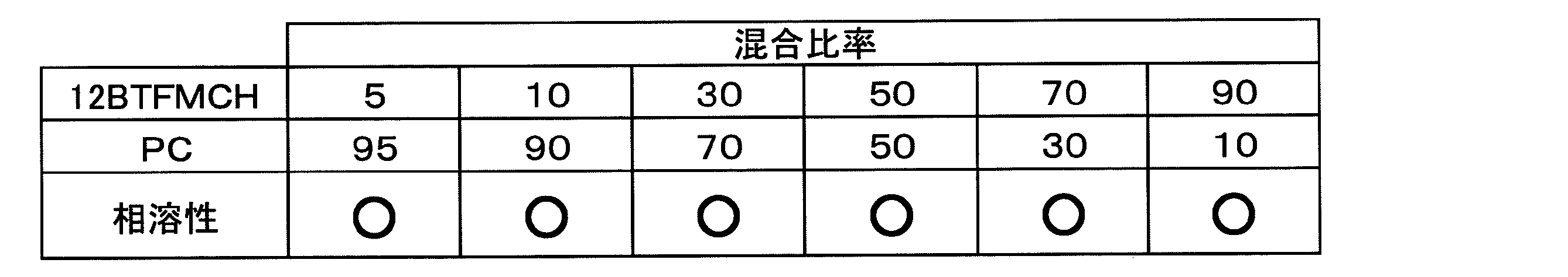
同様に(1-フルオロエチル)シクロへキサン(1FECH)とプロピレンカーボネート(PC)との混合体を作製し、混合体の状態を観察した。結果を表5に示す。

同様に(2-フルオロエチル)シクロへキサン(2FECH)とプロピレンカーボネート(PC)との混合体を作製し、混合体の状態を観察した。結果を表6に示す。


本発明による蓄電デバイス用溶媒を用いて非水電解液を調製し、非水電解液に対して電圧を印加して流れる電流値を測定することにより、蓄電デバイス用溶媒の耐酸化性の評価を行った。
精製したTFMCHに、支持塩としてLiPF6(市販バッテリーグレード)を溶解し、TFMCHの電解液を調製した。TFMCHの非水電解液において、LiPF6濃度は0.1mol/Lとした。
溶媒としてPC(市販バッテリーグレード)を用いた。PCに、支持塩としてLiPF6(市販バッテリーグレード)を溶解し、PC電解液を調製した。実施例1と同様に、PC電解液におけるLiPF6濃度は0.1mol/Lとした。
溶媒としてエチルメチルカーボネート(EMC)(市販バッテリーグレード)を用いた。EMCに、支持塩としてLiPF6(市販バッテリーグレード)を溶解し、EMC電解液を調製した。実施例1と同様に、EMC電解液におけるLiPF6濃度は0.1mol/Lとした。
評価Iと同様の実験を、評価方法を変えて、TFMCH、12BTFMCH、2FECHを用いて行った。
実施例1で精製したTFMCHとジエチルカーボネート(DEC)(市販バッテリーグレード)との体積比10:90の混合溶媒に、支持塩としてLiPF6(市販バッテリーグレード)を溶解した実施例1の電解液を調整した。上記電解液において、LiPF6濃度は0.1mol/Lとした。
実施例1で合成した12BTFMCHとジエチルカーボネート(DEC)(市販バッテリーグレード)との体積比10:90の混合溶媒に、支持塩としてLiPF6(市販バッテリーグレード)を溶解した実施例2の電解液を調整した。上記電解液において、LiPF6濃度は0.1mol/Lとした。
実施例1で合成した2FECHとジエチルカーボネート(DEC)(市販バッテリーグレード)との体積比10:90の混合溶媒に、支持塩としてLiPF6(市販バッテリーグレード)を溶解した実施例3の電解液を調整した。上記電解液において、LiPF6濃度は0.1mol/Lとした。
PC(市販バッテリーグレード)とジエチルカーボネート(DEC)(市販バッテリーグレード)との体積比10:90の混合溶媒に、支持塩としてLiPF6(市販バッテリーグレード)を溶解した比較例1の電解液を調整した。上記電解液において、LiPF6濃度は0.1mol/Lとした。
エチルメチルカーボネート(EMC)(市販バッテリーグレード)とジエチルカーボネート(DEC)(市販バッテリーグレード)の体積比10:90の混合溶媒に、支持塩としてLiPF6(市販バッテリーグレード)を溶解した比較例2の電解液を調整した。上記電解液において、LiPF6濃度は0.1mol/Lとした。
本発明による蓄電デバイス用溶媒と高電圧で充電された正極とを一緒に密封した後に高温で保持した際のガスの発生量を測定した。本実験は、図7に示すフローチャートに従って行った。なお、図7に示すフローチャートのステップ101から103で作製したリチウムイオン二次電池の構造は図1(a)から1(c)に示す通りである。
まず、正極活物質としてLiCoO2(平均粒径10μm、BET法による比表面積0.38m2/g)を準備した。100重量部の活物質に、導電剤であるアセチレンブラックを3重量部、結着剤であるポリフッ化ビニリデンを4重量部、および適量のN-メチル-2-ピロリドンを加え、攪拌・混合して、スラリー状の正極合剤を得た。なお、ポリフッ化ビニリデンは、あらかじめN-メチル-2-ピロリドンに溶解した状態で用いた。
まず、ステンレス(SUS304)製メッシュを図8(b)に示す寸法に打ち抜いて、負極集電体2aを形成した。負極集電体2aは、31mm×41mmの長方形状を有する電極部と、7mm×7mmの正方形状を有するリード取り付け部とを有する。負極集電体2aのうちの電極部の上に、厚さ150μmの金属リチウム2bを圧着して、負極2を得た。
図1(c)に示すように、得られた正極1および負極2を、セパレータ3を介して積層し、電極群13を作製した。セパレータとしては、厚さ20μmのポリエチレン製微多孔質シートを用いた。
ステップ101から103で作製した電池に対して、電流値4mAで4.4Vまで定電流充電を行い、その後、電流値が0.8mAに減衰するまで、4.4Vでの定電圧充電状態を保った。
充電終了後の電池を露点-70℃の不活性ガス雰囲気下で開封して、正極リード11が溶接された正極1を取り出した。次に、取り出した正極1のタブ部を切断し正極リード11を除去した。さらに、タブ部を切断した正極1をジメチルカーボネート(DMC)(市販バッテリーグレード)中に浸漬して正極1中に含まれる電解液を抽出除去した。その後、正極1をDMC中から取り出し、室温真空乾燥によりDMCを除去し、高電圧に充電された正極を得た。
上記充電正極の存在下における溶媒の高温保存時ガス発生能の評価を行うサンプルとして、実施例2-5から2-11、比較例2-5および2-6の9つのサンプルを次に示す方法で作製した。
幅50mm、高さ100mmの一辺が開口した袋状のアルミラミネートフィルムに、上記充電正極を収納した。評価用溶媒として精製したTFMCHを3ml注入した後、減圧状態で開口部を熱溶着することにより、アルミラミネートフィルムを密封した。
評価用溶媒として精製したTFMCHとPC(市販バッテリーグレード)の重量比90:10の混合物を用いた。それ以外の構成は実施例2-5と同様とした。
評価用溶媒として精製したTFMCHとPC(市販バッテリーグレード)の重量比50:50の混合物を用いた。それ以外の構成は実施例2-5と同様とした。
評価用溶媒として精製したTFMCHとPC(市販バッテリーグレード)の重量比10:90の混合物を用いた。それ以外の構成は実施例2-5と同様とした。
評価用溶媒として精製したTFMCHとPC(市販バッテリーグレード)の重量比5:95の混合物を用いた。それ以外の構成は実施例2-5と同様とした。
評価用溶媒として合成した12BTFMCHを用いた。それ以外の構成は実施例2-5と同様とした。
評価用溶媒として合成した2FECHを用いた。それ以外の構成は実施例2-5と同様とした。
評価用溶媒としてPC(市販バッテリーグレード)を用いた。それ以外の構成は実施例2-5と同様とした。
評価用溶媒としてEMC(市販バッテリーグレード)を用いた。それ以外の構成は実施例2-5と同様とした。

(実施例3-1)
実施例3-1として、プロピレンカーボネート(PC)とトリフルオロメチルシクロヘキサン(TFMCH)との重量比率が異なる複数種類の混合溶媒を調製した。それぞれの混合溶媒の重量比率は、97:3、95:5、90:10、85:15、75:25とした。各重量比率の混合溶媒をそれぞれ2サンプルずつ調製し、2サンプルのうちの一方に濃度0.2mol/LのLiPF6を、他方に濃度0.5mol/LのLiPF6を溶解して、10種類の電解液A1、B1、C1、 D1、E1、A2、B2、C2、D2、E2を得た。表9に、電解液のサンプル名と、重量比率および濃度との関係を示す。
比較例として、プロピレンカーボネート(PC)のみを溶媒として含む電解液を2サンプル調製した。2サンプルのうちの一方に濃度0.2mol/LのLiPF6を、他方に濃度0.5mol/LのLiPF6を溶解して、電解液F1、F2を得た。
従来例として、プロピレンカーボネート(PC)とジメチルカーボネート(DMC)を75:25の重量比率で混合した混合溶媒を含む電解液を2サンプル調整した。2サンプルのうちの一方に濃度0.2mol/LのLiPF6を、他方に濃度0.5mol/LのLiPF6を溶解して、電解液G1、G2を得た。

まず、正極活物質としてLiCoO2(平均粒径10μm、BET法による比表面積0.38m2/g)を準備した。100重量部の活物質に、導電剤であるアセチレンブラックを3重量部、結着剤であるポリフッ化ビニリデンを4重量部、および適量のN-メチル-2-ピロリドンを加え、攪拌・混合して、スラリー状の正極合剤を得た。なお、ポリフッ化ビニリデンは、あらかじめN-メチル-2-ピロリドンに溶解した状態で用いた。
まず、ステンレス(SUS304)製メッシュを図8(b)に示す寸法に打ち抜いて、負極集電体2aを形成した。負極集電体2aは、31mm×41mmの長方形状を有する電極部と、7mm×7mmの正方形状を有するリード取り付け部とを有する。負極集電体2aのうちの電極部の上に、厚さ150μmの金属リチウム2bを圧着して、負極2を得た。
得られた正極1および負極2を、セパレータ3を介して積層し、図1(c)に示すような電極群13を作製した。セパレータとしては、厚さ20μmのポリエチレン製微多孔質シートを用いた。
作製した各電池A1、A2、B1・・・G2を用いて高率放電特性の評価を行った。
作製した各電池を用いて高温保存試験を行った。

(実施例4-1)
実施例4-1として、スルホン類としてスルホラン(SLF)、3-メチルスルホラン(3-MeSLF)、およびイソプロピルメチルスルホン(iPrMeSF)を、またフッ素含有環状炭化水素化合物としてトリフルオロメチルシクロヘキサン(TFMCH)、および1,2-ビス(トリフルオロメチル)シクロヘキサン(12BTFMCH)を、さらに支持電解質塩として六フッ化リン酸リチウム(LiPF6)を用いて非水電解液を調製した。表11、表12、表13のそれぞれに調製した非水電解液のサンプル名と組成比率を示す。溶媒の混合比率は重量比率で、支持電解質塩の濃度はmol/Lで示す。なお、TFMCHおよび12BTFMCHには、実施例1において精製したものおよび合成したものを用いた。その他の溶媒および支持電解質塩はいずれも市販のバッテリーグレードとした。


比較例として、プロピレンカーボネート(PC)、スルホラン、3-メチルスルホラン、およびイソプロピルメチルスルホンのみを溶媒として含む非水電解液を調製した。表14に調製した非水電解液のサンプル名と支持電解質塩の濃度はmol/Lで示す。なお、用いた溶媒および支持電解質塩はいずれも市販のバッテリーグレードとした。

従来例として、プロピレンカーボネートとジメチルカーボネート(DMC)を75:25の重量比率で混合した混合溶媒を含む非水電解液を調整した。表15に調製した非水電解液のサンプル名と支持電解質塩の濃度はmol/Lで示す。なお、用いた溶媒および支持電解質塩はいずれも市販のバッテリーグレードとした。

まず、正極活物質としてLiCoO2(平均粒径10μm、BET法による比表面積0.38m2/g)を準備した。100重量部の活物質に、導電剤であるアセチレンブラックを3重量部、結着剤であるポリフッ化ビニリデンを4重量部、および適量のN-メチル-2-ピロリドンを加え、攪拌・混合して、スラリー状の正極合剤を得た。なお、ポリフッ化ビニリデンは、あらかじめN-メチル-2-ピロリドンに溶解した状態で用いた。
まず、ステンレス(SUS304)製メッシュを図8(b)に示す寸法に打ち抜いて、負極集電体2aを形成した。負極集電体2aは、31mm×41mmの長方形状を有する電極部と、7mm×7mmの正方形状を有するリード取り付け部とを有する。負極集電体2aのうちの電極部の上に、厚さ150μmの金属リチウム2bを圧着して、負極2を得た。
得られた正極1および負極2を、セパレータ3を介して積層し、図1(c)に示すような電極群13を作製した。セパレータとしては、厚さ20μmのポリエチレン製微多孔質シートを用いた。

調製した実施例および比較例の電解液のイオン電導度の測定を行った。

作製した実施例、比較例、従来例の電池を用いて高率放電特性の評価を行った。

作製した各電池を用いて高温保存試験を行った。

(実施例5)
実施例5として、プロピレンカーボネート(PC)とトリフルオロメチルシクロヘキサン(TFMCH)とを重量比率80:20で混合して、混合溶媒を調製した。この混合溶媒に、0.2mol/Lの濃度で(C2H5)4NBF4を溶解させて電解液Jを得た。
比較例5として、プロピレンカーボネート(PC)のみを溶媒として含む電解液を調製して、(C2H5)4NBF4を0.2mol/Lの濃度で溶解することにより、電解液Kを得た。
電極は活性炭粉末(比表面積1700m2/g、平均粒子径2μm)を用いて作製した。活性炭粉末100mgとアセチレンブラック20mgとを均一に混合し、ポリビニルピロリドン20mg、メタノール800mgを加えてスラリーを得た。このスラリー状の電極合剤をアルミニウム箔からなる集電体上に塗布し、真空乾燥を行った。電極合剤の塗布重量は、集電体の単位面積あたり2.2mg/cm2であった。得られた極板を、直径12.5mmの円盤状に打ち抜いて電極とした。
円盤状に打ち抜いた電極を用いて、図2に示すようなコイン型電気二重層キャパシタを組み立てた。まず、直径15mmの円形に打ち抜いたポリプロピレン製不織布シートからなるセパレータ17を介して電極22a、22bを互いに対向させて配置させ、電極群とした。電極群をケース20の内部に収容し、所定量の各種電解液J、Kを含浸させた後、ガスケット20を装着した封口板19により、キャパシタ内部を密封した。これにより、電解液Jを用いた電気二重層キャパシタJ、電解液Kを用いた電気二重層キャパシタKを作製した。
作製した電気二重層キャパシタJ、Kに対して、25℃の環境下において、0.1mAの定電流で0Vから2.0Vの電圧範囲での充放電試験を行った。図9(a)に電気二重層キャパシタJ、図9(b)に電気二重層キャパシタKの充放電試験結果を示す。
(実施例6)
実施例6として、スルホラン(SLF)と1,2-ビス(トリフルオロメチル)シクロヘキサン(12BTFMCH)とを重量比率3:1で混合して、混合溶媒を調製した。この混合溶媒に、0.2mol/Lの濃度で(C2H5)4NBF4を溶解させて電解液Lを得た。
比較例6として、プロピレンカーボネート(PC)のみを溶媒として含む電解液を調製して、(C2H5)4NBF4を0.2mol/Lの濃度で溶解することにより、電解液Mを得た。
電極は活性炭粉末(比表面積1700m2/g、平均粒子径2μm)を用いて作製した。活性炭粉末100mgとアセチレンブラック20mgとを均一に混合し、ポリビニルピロリドン20mg、メタノール800mgを加えてスラリーを得た。このスラリー状の電極合剤をアルミニウム箔からなる集電体上に塗布し、真空乾燥を行った。電極合剤の塗布重量は、集電体の単位面積あたり2.2mg/cm2であった。得られた極板を、直径12.5mmの円盤状に打ち抜いて電極とした。
円盤状に打ち抜いた電極を用いて、図2に示すようなコイン型電気二重層キャパシタを組み立てた。まず、直径15mmの円形に打ち抜いたポリプロピレン製不織布シートからなるセパレータ17を介して電極22a、22bを互いに対向させて配置させ、電極群とした。電極群をケース20の内部に収容し、所定量の各種電解液L、Mを含浸させた後、ガスケット20を装着した封口板19により、キャパシタ内部を密封した。これにより、電解液Lを用いた電気二重層キャパシタL、電解液Mを用いた電気二重層キャパシタMを作製した。
作製した電気二重層キャパシタに対して、25℃の環境下において、0.1mAの定電流で0Vから2.0Vの電圧範囲での充放電試験を行った。図10(a)に実施例6の電気二重層キャパシタ、図10(b)に比較例6の電気二重層キャパシタの充放電試験結果を示す。
1a 正極集電体
1b 正極合剤
2 負極
2a 負極集電体
2b 金属リチウム
3 セパレータ
11 正極リード
12 負極リード
13 電極群
14 電池ケース
15 電解液
16a、16b アルミニウム集電体
17 セパレータ
18 スペーサ
19 封口板
20 ガスケット
21 ケース
22a、22b 電極合剤
23a、23b 電極
31 ゴム栓
32 ステンレスワイヤー
33a ステンレスメッシュ
33b Li箔
34 対極
35 参照極
36 作用極
37 Ptワイヤー
38 ガラス容器
30 3極式ガラスセル
Claims (15)
- 下記一般式(1)で表され、かつ、1または2個の置換基Rがシクロヘキサン環に導入された構造を有するフッ素含有環状飽和炭化水素を含む蓄電デバイス用非水溶媒(一般式(1)中、RはCnX2n+1で表され、nは1以上の整数であり、2n+1個のXのうちの少なくとも1つはFであり、それ以外のXはFまたはHである。)。

- 前記nは1または2である請求項1に記載の蓄電デバイス用非水溶媒。
- 25以上の比誘電率を有する化合物をさらに含む請求項2に記載の非水系蓄電デバイス用溶媒。
- 前記25以上の比誘電率を有する化合物はカーボネートまたはスルホンである請求項3に記載の蓄電デバイス用非水溶媒。
- 前記25以上の比誘電率を有する化合物は環状カーボネートである請求項4に記載の蓄電デバイス用非水溶媒。
- 前記25以上の比誘電率を有する化合物は、下記一般式(2)で表わされるスルホン化合物である請求項4に記載の蓄電デバイス用非水溶媒。

- 前記スルホン化合物が鎖状スルホンおよび環状スルホンの少なくとも一方からなる請求項6に記載の蓄電デバイス用非水溶媒。
- 前記鎖状スルホンが非対称の鎖状スルホンである請求項7に記載の蓄電デバイス用非水溶媒。
- 溶媒成分として、前記フッ素含有環状飽和炭化水素を10重量%以上100重量%以下含有する請求項1または2に記載の蓄電デバイス用非水溶媒。
- 請求項1から9のいずれかに記載の蓄電デバイス用非水溶媒と、
支持電解質塩とを備える蓄電デバイス用非水電解液。 - 前記支持電解質塩はリチウム塩である請求項10に記載の蓄電デバイス用非水電解液。
- 前記支持電解質塩は四級アンモニウム塩である、請求項10に記載の蓄電デバイス用非水電解液。
- 請求項1から9のいずれかに記載の蓄電デバイス用非水溶媒または請求項10から12のいずれかに記載の蓄電デバイス用非水電解液を含む蓄電デバイス。
- 請求項1から9のいずれかに記載の蓄電デバイス用非水溶媒または請求項10から12のいずれかに記載の蓄電デバイス用非水電解液を含むリチウムイオン二次電池。
- 請求項1から9のいずれかに記載の蓄電デバイス用非水溶媒または請求項10から12のいずれかに記載の蓄電デバイス用非水電解液を含む電気二重層キャパシタ。
Priority Applications (3)
| Application Number | Priority Date | Filing Date | Title |
|---|---|---|---|
| EP09750361.9A EP2278653B1 (en) | 2008-05-19 | 2009-05-19 | Non-aqueous solvent and non-aqueous electrolyte for an electricity storage device, non-aqueous electricity storage device employing the same, such as lithium secondary battery or electric double-layer capacitor |
| JP2009541664A JP4435866B2 (ja) | 2008-05-19 | 2009-05-19 | 蓄電デバイス用非水溶媒および蓄電デバイス用非水電解液と、それらを用いた非水系蓄電デバイス、リチウム二次電池および電気二重層キャパシタ |
| CN200980118010.2A CN102037599B (zh) | 2008-05-19 | 2009-05-19 | 蓄电装置用非水溶剂和蓄电装置用非水电解液以及采用了它们的非水系蓄电装置、锂二次电池和双电层电容器 |
Applications Claiming Priority (4)
| Application Number | Priority Date | Filing Date | Title |
|---|---|---|---|
| JP2008131175 | 2008-05-19 | ||
| JP2008131174 | 2008-05-19 | ||
| JP2008-131174 | 2008-05-19 | ||
| JP2008-131175 | 2008-05-19 |
Publications (1)
| Publication Number | Publication Date |
|---|---|
| WO2009141999A1 true WO2009141999A1 (ja) | 2009-11-26 |
Family
ID=41339939
Family Applications (1)
| Application Number | Title | Priority Date | Filing Date |
|---|---|---|---|
| PCT/JP2009/002197 WO2009141999A1 (ja) | 2008-05-19 | 2009-05-19 | 蓄電デバイス用非水溶媒および蓄電デバイス用非水電解液と、それらを用いた非水系蓄電デバイス、リチウム二次電池および電気二重層キャパシタ |
Country Status (5)
| Country | Link |
|---|---|
| US (1) | US8211577B2 (ja) |
| EP (1) | EP2278653B1 (ja) |
| JP (2) | JP4435866B2 (ja) |
| CN (1) | CN102037599B (ja) |
| WO (1) | WO2009141999A1 (ja) |
Cited By (3)
| Publication number | Priority date | Publication date | Assignee | Title |
|---|---|---|---|---|
| JP2011023330A (ja) * | 2009-06-18 | 2011-02-03 | Panasonic Corp | 蓄電デバイス用非水溶媒および蓄電デバイス用非水電解液、ならびに、これらを用いた蓄電デバイス、リチウム二次電池および電気二重層キャパシタ |
| WO2012066770A1 (ja) | 2010-11-16 | 2012-05-24 | パナソニック株式会社 | 蓄電デバイス用非水溶媒 |
| CN102870268A (zh) * | 2010-04-26 | 2013-01-09 | 三井化学株式会社 | 含有环状砜化合物的非水电解液及锂二次电池 |
Families Citing this family (11)
| Publication number | Priority date | Publication date | Assignee | Title |
|---|---|---|---|---|
| WO2009141999A1 (ja) | 2008-05-19 | 2009-11-26 | パナソニック株式会社 | 蓄電デバイス用非水溶媒および蓄電デバイス用非水電解液と、それらを用いた非水系蓄電デバイス、リチウム二次電池および電気二重層キャパシタ |
| JP5421253B2 (ja) * | 2008-10-21 | 2014-02-19 | パナソニック株式会社 | 蓄電デバイス用非水溶媒および非水電解液ならびにそれらを用いた蓄電デバイス、リチウム二次電池および電気二重層キャパシタ |
| EP2530779B1 (en) * | 2010-01-28 | 2019-08-14 | Japan Carlit Co., Ltd. | Electrolyte solution for dye sensitized solar cell, and dye sensitized solar cell using same |
| CN102742064B (zh) * | 2010-02-10 | 2015-11-25 | Nec能源元器件株式会社 | 非水性电解质溶液,和具有所述非水性电解质溶液的锂离子二次电池 |
| JP5175906B2 (ja) | 2010-09-07 | 2013-04-03 | 株式会社東芝 | 非水電解質二次電池及び電池パック |
| CN103004007B (zh) * | 2011-06-15 | 2016-10-26 | 松下知识产权经营株式会社 | 蓄电装置用非水溶剂和非水电解液、以及使用它们的蓄电装置、锂二次电池和双电层电容器 |
| WO2014013948A1 (ja) * | 2012-07-18 | 2014-01-23 | 株式会社村田製作所 | 二次電池 |
| US9928970B2 (en) * | 2015-04-23 | 2018-03-27 | Jtekt Corporation | Lithium ion capacitor |
| KR20190027601A (ko) * | 2017-09-07 | 2019-03-15 | 현대자동차주식회사 | 전극용 슬러리, 이를 포함하는 전극 및 리튬 이차전지 |
| US11501927B2 (en) * | 2018-05-02 | 2022-11-15 | Jtekt Corporation | Alkali metal ion capacitor |
| CN112074985A (zh) * | 2018-05-02 | 2020-12-11 | 株式会社捷太格特 | 锂离子二次电池 |
Citations (6)
| Publication number | Priority date | Publication date | Assignee | Title |
|---|---|---|---|---|
| WO2003058746A1 (en) * | 2001-12-28 | 2003-07-17 | Quallion Llc | Electrolyte system and energy storage device using same |
| JP2004111359A (ja) | 2002-07-24 | 2004-04-08 | Mitsubishi Chemicals Corp | 非水系電解液二次電池および非水系電解液 |
| JP2005149750A (ja) | 2003-11-11 | 2005-06-09 | Nec Corp | 非水電解質二次電池 |
| JP2005206600A (ja) * | 2004-01-23 | 2005-08-04 | Air Products & Chemicals Inc | 1,1−ジフルオロビニル脂環式化合物の製造方法 |
| JP2005327785A (ja) * | 2004-05-12 | 2005-11-24 | Honda Motor Co Ltd | 電気二重層キャパシタ用電解液および電気二重層キャパシタ |
| JP2006286650A (ja) | 2002-07-24 | 2006-10-19 | Mitsubishi Chemicals Corp | 非水系電解液二次電池および非水系電解液 |
Family Cites Families (11)
| Publication number | Priority date | Publication date | Assignee | Title |
|---|---|---|---|---|
| JP3856583B2 (ja) * | 1999-02-01 | 2006-12-13 | 三井化学株式会社 | 二次電池用非水電解液および非水電解液二次電池 |
| JP3721857B2 (ja) | 1999-06-04 | 2005-11-30 | 株式会社日立製作所 | 不燃性電解液及びこれを用いたリチウム2次電池 |
| JP2001085058A (ja) | 1999-09-20 | 2001-03-30 | Hitachi Ltd | 非水電解液及びこれを用いたリチウム1次電池及びリチウム2次電池及び電気化学キャパシタ及び高分子電解質及びこれを用いたポリマ2次電池 |
| JP2001143749A (ja) * | 1999-11-19 | 2001-05-25 | Nippon Zeon Co Ltd | 非水電解液含有電気化学素子 |
| JP4212301B2 (ja) * | 2002-05-16 | 2009-01-21 | 三菱化学株式会社 | 非水系電解液二次電池 |
| EP2133895A1 (en) | 2004-01-15 | 2009-12-16 | Panasonic Corporation | Nonaqueous electrolyte for electrochemical devices |
| JP4728647B2 (ja) | 2004-01-15 | 2011-07-20 | パナソニック株式会社 | 非水電解液を含む電気二重層コンデンサもしくは二次電池 |
| EP1560236B1 (en) | 2004-01-28 | 2006-06-07 | Honda Motor Co., Ltd. | Electric double layer capacitor and electrolyte solution therefor |
| JP2005217008A (ja) * | 2004-01-28 | 2005-08-11 | Honda Motor Co Ltd | 電気二重層キャパシタ用電解液および電気二重層キャパシタ |
| JP5088918B2 (ja) | 2006-01-24 | 2012-12-05 | 国立大学法人鳥取大学 | イオン液体およびその製造方法、ならびに該イオン液体を含む電解コンデンサ |
| WO2009141999A1 (ja) | 2008-05-19 | 2009-11-26 | パナソニック株式会社 | 蓄電デバイス用非水溶媒および蓄電デバイス用非水電解液と、それらを用いた非水系蓄電デバイス、リチウム二次電池および電気二重層キャパシタ |
-
2009
- 2009-05-19 WO PCT/JP2009/002197 patent/WO2009141999A1/ja active Application Filing
- 2009-05-19 EP EP09750361.9A patent/EP2278653B1/en active Active
- 2009-05-19 CN CN200980118010.2A patent/CN102037599B/zh active Active
- 2009-05-19 US US12/468,554 patent/US8211577B2/en active Active
- 2009-05-19 JP JP2009541664A patent/JP4435866B2/ja not_active Expired - Fee Related
- 2009-12-21 JP JP2009288698A patent/JP2010108940A/ja active Pending
Patent Citations (6)
| Publication number | Priority date | Publication date | Assignee | Title |
|---|---|---|---|---|
| WO2003058746A1 (en) * | 2001-12-28 | 2003-07-17 | Quallion Llc | Electrolyte system and energy storage device using same |
| JP2004111359A (ja) | 2002-07-24 | 2004-04-08 | Mitsubishi Chemicals Corp | 非水系電解液二次電池および非水系電解液 |
| JP2006286650A (ja) | 2002-07-24 | 2006-10-19 | Mitsubishi Chemicals Corp | 非水系電解液二次電池および非水系電解液 |
| JP2005149750A (ja) | 2003-11-11 | 2005-06-09 | Nec Corp | 非水電解質二次電池 |
| JP2005206600A (ja) * | 2004-01-23 | 2005-08-04 | Air Products & Chemicals Inc | 1,1−ジフルオロビニル脂環式化合物の製造方法 |
| JP2005327785A (ja) * | 2004-05-12 | 2005-11-24 | Honda Motor Co Ltd | 電気二重層キャパシタ用電解液および電気二重層キャパシタ |
Non-Patent Citations (1)
| Title |
|---|
| See also references of EP2278653A4 |
Cited By (3)
| Publication number | Priority date | Publication date | Assignee | Title |
|---|---|---|---|---|
| JP2011023330A (ja) * | 2009-06-18 | 2011-02-03 | Panasonic Corp | 蓄電デバイス用非水溶媒および蓄電デバイス用非水電解液、ならびに、これらを用いた蓄電デバイス、リチウム二次電池および電気二重層キャパシタ |
| CN102870268A (zh) * | 2010-04-26 | 2013-01-09 | 三井化学株式会社 | 含有环状砜化合物的非水电解液及锂二次电池 |
| WO2012066770A1 (ja) | 2010-11-16 | 2012-05-24 | パナソニック株式会社 | 蓄電デバイス用非水溶媒 |
Also Published As
| Publication number | Publication date |
|---|---|
| EP2278653B1 (en) | 2014-03-05 |
| JPWO2009141999A1 (ja) | 2011-09-29 |
| EP2278653A4 (en) | 2013-04-10 |
| CN102037599A (zh) | 2011-04-27 |
| EP2278653A1 (en) | 2011-01-26 |
| JP4435866B2 (ja) | 2010-03-24 |
| CN102037599B (zh) | 2014-10-29 |
| US20090297954A1 (en) | 2009-12-03 |
| US8211577B2 (en) | 2012-07-03 |
| JP2010108940A (ja) | 2010-05-13 |
Similar Documents
| Publication | Publication Date | Title |
|---|---|---|
| JP4435866B2 (ja) | 蓄電デバイス用非水溶媒および蓄電デバイス用非水電解液と、それらを用いた非水系蓄電デバイス、リチウム二次電池および電気二重層キャパシタ | |
| JP5308314B2 (ja) | 蓄電デバイス用非水溶媒および蓄電デバイス用非水電解液、ならびに、これらを用いた蓄電デバイス、リチウム二次電池および電気二重層キャパシタ | |
| JP5421253B2 (ja) | 蓄電デバイス用非水溶媒および非水電解液ならびにそれらを用いた蓄電デバイス、リチウム二次電池および電気二重層キャパシタ | |
| JP5948646B2 (ja) | 蓄電デバイス用非水溶媒および非水電解液ならびにそれらを用いた蓄電デバイス、リチウム二次電池および電気二重層キャパシタ | |
| JP7116311B2 (ja) | 非水電解液電池用電解液及びそれを用いた非水電解液電池 | |
| US20040002002A1 (en) | Material for electrolytic solutions and use thereof | |
| JP5306749B2 (ja) | 電気化学デバイス | |
| JPWO2005003108A1 (ja) | 第4級アンモニウム塩および電解質並びに電気化学デバイス | |
| JP2004342607A (ja) | リチウム電池用非水電解液およびその製造方法ならびにリチウムイオン二次電池 | |
| JP6913159B2 (ja) | 電池用非水電解液及びリチウム二次電池 | |
| JP5165862B2 (ja) | 非水電解液およびそれを用いた電気化学エネルギー蓄積デバイス | |
| JP5335218B2 (ja) | 非水電解液二次電池 | |
| WO2016006315A1 (ja) | 3,3,3-トリフルオロプロピオネート基を有するエステルを含む非水電解液、及びそれを用いた非水電解液電池 | |
| JP7345502B2 (ja) | 電池用非水電解液及びリチウム二次電池 | |
| JP5059987B2 (ja) | 蓄電デバイス用非水溶媒 | |
| JP2018170217A (ja) | 電池用非水電解液及びリチウム二次電池 | |
| JP2018170238A (ja) | 電池用非水電解液及びリチウム二次電池 | |
| JP7395816B2 (ja) | 電池用非水電解液及びリチウム二次電池 | |
| JP6980502B2 (ja) | 電池用非水電解液及びリチウム二次電池 | |
| WO2014097618A1 (ja) | 蓄電デバイス用非水溶媒、非水電解液、ならびにこれを用いた蓄電デバイスおよびリチウム二次電池 | |
| KR101175134B1 (ko) | 실리콘 화합물을 포함하는 전해질 조성물 및 이를 함유하는 리튬 전지 | |
| JP2018190569A (ja) | 電池用非水電解液、電池用添加剤、及びリチウム二次電池 | |
| JP7206556B2 (ja) | 電池用非水電解液及びリチウム二次電池 |
Legal Events
| Date | Code | Title | Description |
|---|---|---|---|
| WWE | Wipo information: entry into national phase |
Ref document number: 200980118010.2 Country of ref document: CN |
|
| WWE | Wipo information: entry into national phase |
Ref document number: 2009541664 Country of ref document: JP |
|
| 121 | Ep: the epo has been informed by wipo that ep was designated in this application |
Ref document number: 09750361 Country of ref document: EP Kind code of ref document: A1 |
|
| WWE | Wipo information: entry into national phase |
Ref document number: 2009750361 Country of ref document: EP |
|
| WWE | Wipo information: entry into national phase |
Ref document number: 7245/CHENP/2010 Country of ref document: IN |
|
| NENP | Non-entry into the national phase |
Ref country code: DE |