WO2009122832A1 - 電子写真現像剤用キャリア芯材及びその製造方法、キャリア及びその製造方法並びに該キャリアを用いた電子写真現像剤 - Google Patents
電子写真現像剤用キャリア芯材及びその製造方法、キャリア及びその製造方法並びに該キャリアを用いた電子写真現像剤 Download PDFInfo
- Publication number
- WO2009122832A1 WO2009122832A1 PCT/JP2009/053676 JP2009053676W WO2009122832A1 WO 2009122832 A1 WO2009122832 A1 WO 2009122832A1 JP 2009053676 W JP2009053676 W JP 2009053676W WO 2009122832 A1 WO2009122832 A1 WO 2009122832A1
- Authority
- WO
- WIPO (PCT)
- Prior art keywords
- core material
- carrier
- carrier core
- particles
- electrophotographic developer
- Prior art date
Links
Classifications
-
- G—PHYSICS
- G03—PHOTOGRAPHY; CINEMATOGRAPHY; ANALOGOUS TECHNIQUES USING WAVES OTHER THAN OPTICAL WAVES; ELECTROGRAPHY; HOLOGRAPHY
- G03G—ELECTROGRAPHY; ELECTROPHOTOGRAPHY; MAGNETOGRAPHY
- G03G9/00—Developers
- G03G9/08—Developers with toner particles
- G03G9/10—Developers with toner particles characterised by carrier particles
- G03G9/107—Developers with toner particles characterised by carrier particles having magnetic components
- G03G9/1075—Structural characteristics of the carrier particles, e.g. shape or crystallographic structure
-
- G—PHYSICS
- G03—PHOTOGRAPHY; CINEMATOGRAPHY; ANALOGOUS TECHNIQUES USING WAVES OTHER THAN OPTICAL WAVES; ELECTROGRAPHY; HOLOGRAPHY
- G03G—ELECTROGRAPHY; ELECTROPHOTOGRAPHY; MAGNETOGRAPHY
- G03G9/00—Developers
- G03G9/08—Developers with toner particles
- G03G9/10—Developers with toner particles characterised by carrier particles
- G03G9/113—Developers with toner particles characterised by carrier particles having coatings applied thereto
- G03G9/1131—Coating methods; Structure of coatings
-
- G—PHYSICS
- G03—PHOTOGRAPHY; CINEMATOGRAPHY; ANALOGOUS TECHNIQUES USING WAVES OTHER THAN OPTICAL WAVES; ELECTROGRAPHY; HOLOGRAPHY
- G03G—ELECTROGRAPHY; ELECTROPHOTOGRAPHY; MAGNETOGRAPHY
- G03G9/00—Developers
- G03G9/08—Developers with toner particles
- G03G9/10—Developers with toner particles characterised by carrier particles
- G03G9/113—Developers with toner particles characterised by carrier particles having coatings applied thereto
- G03G9/1132—Macromolecular components of coatings
Definitions
- the present invention relates to a carrier core material for an electrophotographic developer used in a two-component electrophotographic developer used in a copying machine, a printer, and the like, a manufacturing method thereof, a carrier, a manufacturing method thereof, and an electrophotography using the carrier. It relates to a developer.
- the electrophotographic development method is a method in which toner particles in a developer are attached to an electrostatic latent image formed on a photoreceptor and developed, and the developer used in this method is composed of toner particles and carrier particles.
- the carrier particles are agitated together with the toner particles in the developing box filled with the developer, thereby imparting a desired charge to the toner particles, and thus being charged.
- the carrier particles remaining on the developing roll holding the magnet are returned to the developing box from the developing roll, mixed and stirred with new toner particles, and used repeatedly for a certain period.
- the two-component developer has the function of mixing and stirring the carrier particles with the toner particles, charging the toner particles, and further transporting the toner particles. Good controllability. Therefore, the two-component developer is suitable for a full-color developing device that requires high image quality and a device that performs high-speed printing that requires image maintenance reliability and durability.
- image characteristics such as image density, fog, vitiligo, gradation, and resolving power show predetermined values from the initial stage, and these characteristics are in the printing life period. It needs to be kept stable without fluctuating inside. In order to maintain these characteristics stably, it is necessary that the characteristics of the carrier particles contained in the two-component developer are stable.
- iron powder carriers such as iron powder whose surface is covered with an oxide film or iron powder whose surface is coated with a resin have been used as carrier particles for forming a two-component developer. Since such an iron powder carrier has high magnetization and high conductivity, there is an advantage that an image with good reproducibility of the solid portion can be easily obtained.
- such an iron powder carrier has a heavy true specific gravity of about 7.8 and is too high in magnetization, so that the toner constituent components on the surface of the iron powder carrier are mixed by stirring and mixing with toner particles in the developing box. Fusing, so-called toner spent, is likely to occur. The generation of such toner spent reduces the effective carrier surface area and tends to reduce the triboelectric charging ability with the toner particles.
- the resin on the surface peels off due to stress during durability, and the core material (iron powder) with high conductivity and low dielectric breakdown voltage is exposed, which may cause charge leakage. . Due to such charge leakage, the electrostatic latent image formed on the photoconductor is destroyed, and a crack or the like is generated in the solid portion, so that it is difficult to obtain a uniform image. For these reasons, iron powder carriers such as oxide-coated iron powder and resin-coated iron powder are no longer used.
- a predetermined amount of the ferrite carrier raw material is mixed, calcined, pulverized, and calcined after granulation. Depending on conditions, calcining may be omitted. is there.
- the firing process which is the process of generating magnetization by the ferritization reaction, generally uses a tunnel kiln, and fills the kiln with raw materials and fires it.
- the firing time requires about 12 hours including the temperature raising time, the maximum temperature holding time, and the temperature lowering time, and the one that has become a block after firing must be crushed, and the production stability is improved. There is a problem that it is not good.
- the carrier core (core) material manufactured by such a firing method includes not only cracked and chipped particles but also deformed particles having deformed particles, a uniform coating can be formed even if a resin coating is formed. It is difficult to form.
- the resin coating is thicker at the depressions on the particle surface and thinner at the protrusions. In the portion where the thickness of the resin coating is thin, the carrier core material is quickly exposed due to the stress, causing a leak phenomenon and a spread of the charge amount distribution, and it is difficult to stabilize high-quality image quality for a long period of time.
- Patent Document 1 Japanese Patent Application Laid-Open No. Sho 62-50839
- a compound composed of a metal oxide blended as a raw material for forming ferrite is passed through a high-temperature flame atmosphere, thereby instantly blending the compound.
- a method for producing a ferrite carrier to be ferritized is described.
- the ratio of oxygen amount / combustion gas is 3 or less, and firing is difficult depending on the ferrite raw material. Further, it is not suitable for the production of ferrite having a small particle size of, for example, about 20 to 50 ⁇ m, corresponding to the recent reduction in particle size of carriers, and spherical homogeneous ferrite particles cannot be obtained.
- Patent Document 2 International Publication No. 2007-63933 uses the above-described spraying method, uses a combustion gas and oxygen as a combustible gas combustion flame, and sets the volume ratio of the combustion gas and oxygen to 1: 3.
- a method for producing a resin-coated ferrite carrier having a thickness of from 5 to 6.0 is described, and the resin-coated ferrite carrier produced in this way has fine lines for improving the adhesion strength of the carrier core surface to the resin coating. It is said to have irregularities that are wrinkled patterns.
- true spherical particles produced by the conventional thermal spraying method can produce only particles having good fluidity but high apparent density. Therefore, even if the fluidity is good, there is a concern that the toner is destroyed in the developing device if the stirring stress is strong.
- Patent Document 3 Japanese Patent Laid-Open No. 7-237923 describes ferrite-containing hollow particles.
- the hollow particles are obtained without performing a heat treatment such as firing, but do not obtain hollow particles of several ⁇ m to several tens of ⁇ m.
- it is said that, for example, it is said that it can be used as a carbon dioxide fixing catalyst by wash-coating a honeycomb carrier having a monolithic structure, drying it, firing it if necessary, and using it as a carbon dioxide fixing catalyst. It is not a thing.
- Patent Document 4 Japanese Patent Application Laid-Open No. 2005-294357 describes a method for producing ferrite hollow particles. Acrylic resin particles that disappear during firing are coated with fine powder as a ferrite raw material, and then subjected to main firing to form hollow ferrite. Although particles are obtained, an acrylic resin for forming a hollow is essential. In addition, since the firing is performed in a normal electric furnace, there is a concern that the particles are coalesced and fused at the time of firing. Furthermore, although the electromagnetic shielding material is mentioned as the use, it is not used for the carrier core material for electronic developers.
- Patent Document 5 Japanese Patent Application Laid-Open No. 2007-34249 discloses a carrier core material for an electrophotographic developer having a hollow structure with an apparent density of 2.0 g / cm 3 or less and an apparent density / true density within a certain range. Are listed. Patent Document 5 describes that carbon dioxide gas, water vapor, and the like are generated during calcination to form pores in particles before firing. Moreover, low specific gravity is going to be achieved by adding silica powder with light specific gravity. In this way, it is extremely difficult to obtain a spherical and smooth surface by the method of controlling the apparent density and / or the true specific gravity by forming the pores.
- Patent Documents 3 to 5 all disclose hollow particles, but it is necessary to add a substance for forming a hollow beforehand, and this substance tends to remain depending on the firing conditions. was there. Further, each hollow particle has the above-described problems.
- the carrier core material for electrophotographic developer is desired to be spherical and excellent in strength. Further, there is a demand for a carrier core material that can control the true density and / or the apparent density while maintaining a true spherical shape.
- a carrier core material that can control the true density and / or the apparent density while maintaining a true spherical shape.
- an object of the present invention is to provide a carrier core material for an electrophotographic developer that is spherical, excellent in strength, and capable of controlling the true density and / or apparent density, a manufacturing method thereof, a carrier and a manufacturing method thereof, and It is to provide an electrophotographic developer used.
- the present inventors have achieved the above object by a carrier core material having a certain range of hollow particles, and such a carrier core material is manufactured by a thermal spraying method. The inventors have found that this is possible and have arrived at the present invention.
- the present invention provides a carrier core material for an electrophotographic developer containing 3 to 100% by number of hollow particles having an iron content of 36 to 78% by weight.
- the carrier core material for an electrophotographic developer according to the present invention preferably has an average particle size of 20 to 150 ⁇ m.
- the carrier core material for an electrophotographic developer according to the present invention preferably has a true specific gravity of 2.5 to 4.75 g / cm 3 .
- the carrier core material for an electrophotographic developer according to the present invention preferably has an apparent density of 1.5 to 2.6 g / cm 3 .
- the carrier core material for an electrophotographic developer according to the present invention preferably has a magnetization of 5 to 95 Am 2 / kg (emu / g).
- the carrier core material for an electrophotographic developer according to the present invention has 0.10 ⁇ d when the outer diameter (average particle diameter) of the core material is d 1 and the outer diameter of the hollow portion existing inside the core material is d 2. It is desirable that 2 / d 1 ⁇ 0.90.
- the present invention provides a carrier for an electrophotographic developer obtained by coating the surface of a carrier core material with a resin.
- the present invention relates to a method for producing a carrier core material for an electronic developer, characterized in that a granulated product obtained by preparing a carrier core material together with a binder is sprayed in the atmosphere to form a ferrite and then rapidly solidified. Is to provide.
- the apparent density of the granulated product is preferably 0.4 to 1.0 g / cm 3 .
- the content of the binder in the granulated product is preferably 0.8 to 3.5% by weight in terms of solid content.
- the present invention provides a method for producing a carrier for an electronic developer obtained by coating the surface of the carrier core material obtained by the above-described method for producing a carrier core material for an electronic developer.
- the present invention provides an electrophotographic developer comprising the carrier and toner.
- the carrier core material and carrier for an electrophotographic developer according to the present invention are spherical, have excellent strength, and can control true density and / or apparent density. Moreover, the carrier core material and the carrier can be suitably produced by the production method of the present invention.
- the electrophotographic developer using the carrier can reduce stress on the toner in the stirring with the toner in the developing device.
- the carrier core material for an electrophotographic developer according to the present invention contains 3 to 100%, preferably 3 to 60%, more preferably 3 to 40%, hollow particles having an iron content of 36 to 78% by weight. %contains.
- the iron content is less than 36% by weight, it means that iron is not the main component. Since the iron oxide containing the most iron is FeO, it does not exceed 78% by weight.
- the hollow particles are smaller than 3% by number, the effect of the present invention cannot be obtained without changing from ordinary core particles not containing hollow particles.
- the ratio of the hollow particles is determined as the number of hollow particles included in one field of view / the total number of particles included in one field of view by taking a photograph of the cross section of the core material particles by SEM at a magnification of 200 times. Moreover, the content of Fe and the contents of Mg and Ti described later are measured as follows.
- the carrier core material for an electrophotographic developer according to the present invention preferably has an average particle size of 20 to 150 ⁇ m, more preferably 20 to 100 ⁇ m, and most preferably 25 to 100 ⁇ m.
- the average particle size is smaller than 20 ⁇ m, it is extremely difficult to produce by the production method of the present invention.
- a carrier using particles having an average particle size larger than 150 ⁇ m as an electrophotographic carrier core material is not preferable because the image quality deteriorates.
- the average particle size is measured as follows.
- the average particle diameter was measured by a laser diffraction scattering method.
- a Microtrac particle size analyzer (Model 9320-X100) manufactured by Nikkiso Co., Ltd. was used as an apparatus.
- the refractive index was 2.42, and the measurement was performed in an environment of 25 ⁇ 5 ° C. and humidity 55 ⁇ 15%.
- the average particle diameter (median diameter) referred to here is the cumulative 50% particle diameter in the volume distribution mode and under the sieve display.
- the carrier sample was dispersed using a 0.2% sodium hexametaphosphate aqueous solution as a dispersion, and subjected to ultrasonic treatment for 1 minute using an ultrasonic sonic homogenizer (UH-3C) manufactured by Ultrasonic Industries.
- UH-3C ultrasonic sonic homogenizer
- the carrier core material for an electrophotographic developer according to the present invention preferably has a true specific gravity of 2.5 to 4.75 g / cm 3 , more preferably 3.5 to 4.75 g / cm 3 , Most desirably, it is 3.8 to 4.75 g / cm 3 .
- Those having a true specific gravity of greater than 4.75 g / cm 3 are not different from ordinary core particles, and thus the effects of the present invention cannot be obtained.
- the true specific gravity is smaller than 2.5 g / cm 3 , even if hollow particles can be generated, the strength of the particles is inferior, so that it cannot be used as a carrier core material for electrophotography.
- the true specific gravity is measured as follows.
- the true specific gravity was measured using a pycnometer in accordance with JIS R9301-2-1. Here, methanol was used as a solvent, and measurement was performed at a temperature of 25 ° C.
- the carrier core material for an electrophotographic developer according to the present invention is preferably an apparent density of 1.5 ⁇ 2.6g / cm 3, and more desirably 1.6 ⁇ 2.55g / cm 3, Most preferably, it is 1.65 to 2.50 g / cm 3 .
- the apparent density is smaller than 1.5 g / cm 3 , even if hollow particles can be generated, the strength of the particles is inferior, so that it cannot be used as a carrier core material for electrophotography.
- it is larger than 2.6 g / cm 3, it is not different from normal core particles.
- Apparent density is measured by:
- the apparent density is measured according to JIS-Z2504 (Apparent density test method for metal powder).
- the specific gravity can be determined by the size of the hollow existing inside the particle, and the influence of the unevenness of the particle surface is not only very small but also always has a smooth particle surface. be able to. Further, particles having a large number of pores have a very low mechanical strength as they are, and for example, a treatment such as pouring (filling) a large amount of resin is indispensable for use as a carrier core material for an electrophotographic developer.
- the hollow particles according to the present invention have a hard shell on the outside like eggs and can have a strong structure.
- the strength of the particle may not be reduced between the inner hollow part and the outer side of the particle, and the hollow part existing inside the particle and the outer side of the particle may be connected with pores in a state where there is not much unevenness on the particle surface. it can. Therefore, the apparent density can be controlled while maintaining the true specific gravity in the same manner as that of ordinary ferrite particles. Even if the hollow portion is connected to the outside of the particle, not only the apparent density of the particle but also the true specific gravity can be controlled by closing the pores near the surface with a resin or the like.
- the carrier core material for an electrophotographic developer according to the present invention preferably has a magnetization of 5 to 95 Am 2 / kg (emu / g) at 5K ⁇ 1000 / 4 ⁇ ⁇ A / m. Since iron is the main component and does not exceed magnetite, the magnetization does not exceed 95 Am 2 / kg. In addition, when the magnetization is smaller than 5 Am 2 / kg (emu / g), there is a possibility that heat is not sufficiently transferred to the particles, and the particles are insufficient in strength for use in electrophotographic applications. Is not preferable. Magnetization is measured by:
- Magneticization Magnetization was performed using a vibrating sample magnetometer (model: VSM-C7-10A (manufactured by Toei Kogyo Co., Ltd.)). The measurement sample was packed in a cell having an inner diameter of 5 mm and a height of 2 mm and set in the apparatus. The measurement was performed by applying an applied magnetic field and sweeping to a maximum of 5 K ⁇ 1000 / 4 ⁇ ⁇ A / m (5 KOe). Next, the applied magnetic field was decreased to prepare a hysteresis curve on the recording paper. Magnetization was determined from the data of this curve.
- the carrier core material for an electrophotographic developer according to the present invention preferably contains Mg 12% by weight or less and / or Ti 12% by weight or less.
- Mg is more than 12% by weight
- Mg is not taken in as ferrite, so it remains as MgO on the particle surface and / or inside the particle, reacts with moisture and carbon dioxide in the air to become Mg (OH) 2 or MgCO 3 , Environmental dependency is worse.
- Ti is more than 12% by weight, TiO 2 does not become Fe 2 TiO 5 and / or FeTiO 3 but only TiO 2 is present on the particle surface and / or inside the particle, so that charging characteristics for a negatively chargeable toner are reduced. It is not good because it causes aggravation.
- the contents of Mg and Ti are measured by the method described above.
- the carrier core material for an electrophotographic developer according to the present invention has 0.1 ⁇ d 2 / d 1 ⁇ when the outer diameter of the core material is d 1 and the outer diameter of the hollow portion existing inside the core material is d 2. 0.9 is desirable, 0.1 ⁇ d 2 / d 1 ⁇ 0.8 is more desirable, and 0.1 ⁇ d 2 / d 1 ⁇ 0.65 is most desirable.
- d 2 / d 1 is 0.10 or less, the hollow portion is small and is not different from ordinary core particles.
- d 2 / d 1 is 0.90 or more, even if hollow particles can be generated, the strength of the particles is inferior, so that it cannot be used as a carrier core material for an electrophotographic developer.
- d 1 and d 2 are based on the measurement of the SEM photograph of the particle cross section.
- the particle cross section does not necessarily allow the central portion (maximum diameter) of the core particle particles to be observed, and there is a possibility of observing a portion shifted from the central portion.
- the hollow portion is not necessarily generated at the center portion of the core particle, and attention is paid to the case where the hollow portion is observed to deviate from the center portion and / or the plurality of hollow portions are generated in two or more. is required. Specifically, it is measured by the following.
- the shape factor SF-1 of the carrier core material for an electrophotographic developer according to the present invention is 100 to 120. When the thermal spraying method is used, the shape factor SF-1 does not exceed 120. This shape factor SF-1 is measured as follows.
- Shape factor SF-1 JSM-6060A manufactured by JEOL Ltd. was used, the acceleration voltage was 20 kV, and the carrier SEM was photographed in a 450 ⁇ field of view with particles dispersed so as not to overlap, and the image information was made by Media Cybernetics through the interface. It is a value obtained by introducing into image analysis software (Image-Pro PLUS), performing analysis, obtaining Area (area) and ferret diameter (maximum), and calculating from the following formula. The closer the carrier shape is to a spherical shape, the closer to 100. The shape index SF-1 was calculated for each particle, and the average value of 100 particles was defined as the shape index SF-1 of the carrier.
- the specific surface area of the carrier core material for an electrophotographic developer according to the present invention is desirably 0.065 ⁇ 0.65m 2 / g, more preferably to be 0.08 ⁇ 0.6m 2 / g, Most preferably, it is 0.1 to 0.6 m 2 / g.
- the specific surface area is less than 0.065 m 2 / g, it means that there is almost no unevenness on the particle surface, and it is difficult to obtain the anchor effect of the resin when the resin coating is performed, and it is coated when used as a developer. This is not good because the resin may be easily peeled off and the charging characteristics and resistance may change.
- the specific surface area was measured using a specific surface area measuring device GEMINI 2360 manufactured by Shimadzu Corporation. About 10 to 15 g of a measurement sample was put in a measurement cell, accurately weighed with a precision balance, and after weighing, vacuum suction heat treatment was performed at 200 ° C. for 60 minutes in a gas port attached to the apparatus. Next, a sample was set in the measurement port, and measurement was started. Measurement is performed by the 10-point method, and the BET specific surface area is automatically calculated when the weight of the sample is input at the end of the measurement.
- Measurement cell spherical outer shape 1.9 cm (3/4 inch), length 3.8 cm (1-1 / 2 inch), cell length 15.5 (6.1 inch), volume 12.0 cm 3 , sample Capacity 6.00 cm 3 Environment: Temperature: 10-30 ° C, Humidity: 20-80% relative humidity, no condensation
- the carrier core material for an electrophotographic developer according to the present invention preferably has an oxidized surface.
- the thickness of the oxide film formed by this oxidation treatment is preferably 0.1 nm to 5 ⁇ m. If the thickness is less than 0.1 nm, the effect of the oxide film layer is small, and if it exceeds 5 ⁇ m, the magnetization is lowered or the resistance becomes too high, so that problems such as a reduction in developing ability tend to occur. Moreover, you may reduce
- the electrophotographic developer carrier according to the present invention is obtained by coating the surface of the carrier core material with a resin.
- the resin-coated carrier for an electrophotographic developer according to the present invention desirably has a resin coating amount of 0.1 to 10% by weight with respect to the carrier core material. If the coating amount is less than 0.01% by weight, it is difficult to form a uniform coating layer on the surface of the carrier. If the coating amount exceeds 10% by weight, the carriers are aggregated with a decrease in productivity such as a decrease in yield. This causes fluctuations in developer characteristics such as fluidity or charge amount in the actual machine.
- the film forming resin used here can be appropriately selected depending on the toner to be combined, the environment in which it is used, and the like.
- the type is not particularly limited, for example, fluorine resin, acrylic resin, epoxy resin, polyamide resin, polyamideimide resin, polyester resin, unsaturated polyester resin, urea resin, melamine resin, alkyd resin, phenol resin, fluorine acrylic resin, Examples thereof include acrylic-styrene resins, silicone resins, or modified silicone resins modified with resins such as acrylic resins, polyester resins, epoxy resins, polyamide resins, polyamideimide resins, alkyd resins, urethane resins, and fluororesins.
- thermosetting resin In view of the detachment of the resin due to mechanical stress during use, a thermosetting resin is preferably used.
- the thermosetting resin include epoxy resins, phenol resins, silicone resins, unsaturated polyester resins, urea resins, melamine resins, alkyd resins, and resins containing them.
- a conductive agent can be added to the film forming resin for the purpose of controlling the electrical resistance, charge amount, and charging speed of the carrier. Since the conductive agent has a low electric resistance, if the addition amount is too large, it is likely to cause a rapid charge leak. Accordingly, the addition amount is 0.25 to 20.0% by weight, preferably 0.5 to 15.0% by weight, particularly preferably 1.0 to 10.0% by weight, based on the solid content of the film-forming resin. %.
- the conductive agent include conductive carbon, oxides such as titanium oxide and tin oxide, and various organic conductive agents.
- the film forming resin can contain a charge control agent.
- the charge control agent include various charge control agents generally used for toners and various silane coupling agents. This is because, when the core material exposed area is controlled to be relatively small by film formation, the charge imparting ability may decrease, but it can be controlled by adding various charge control agents and silane coupling agents. It is.
- the types of charge control agents and coupling agents that can be used are not particularly limited, but charge control agents such as nigrosine dyes, quaternary ammonium salts, organometallic complexes, metal-containing monoazo dyes, aminosilane coupling agents, and fluorine-based silane couplings An agent or the like is preferable.
- the method for producing a carrier core material for an electrophotographic developer according to the present invention comprises subjecting a granulated product obtained by preparing a carrier core material together with a binder to thermal spraying in the atmosphere to form ferrite, followed by rapid solidification. Get the core material.
- the method for preparing the granulated product using the carrier core material is not particularly limited, and a conventionally known method can be adopted. Either a dry method or a wet method may be used.
- the apparent density of the granulated product is desirably 0.4 to 1.0 g / cm 3 .
- the apparent density is less than 0.4 g / cm 3 , the hollow portion may be too large, and the particles may be easily broken.
- it is larger than 1.0 g / cm 3 , a sufficient hollow portion cannot be formed, and there is a possibility that hollow particles cannot be obtained.
- This apparent density is measured by the method described above.
- FeOOH As the iron component raw material of the carrier core material. Since FeOOH has a large volume change, desired hollow particles can be obtained. On the other hand, since Fe 2 O 3 and Fe 3 O 4 have a smaller volume change than FeOOH, there is a high possibility that hollow particles cannot be obtained.
- the raw material having a large volume change here means that the raw material particles themselves are highly shrunk when fired and / or that the crystal structure is shrunk greatly when fired.
- FeOOH goethite and / or rapid crosite
- the content of the binder used together with the carrier raw material is preferably 0.8 to 3.5% by weight in terms of solid content in the granulated product.
- the binder content is less than 0.8% by weight in terms of solid content, a hollow part is formed at the time of thermal spraying, and sufficient gas is not generated to maintain, so that hollow particles are difficult to obtain, exceeding 3.5% by weight.
- the thermal spraying is performed, the hollow part is formed and the gas for maintaining is excessive, the hollow part becomes too large, and the particles are destroyed, so that it becomes difficult to obtain the hollow particles.
- PVA polyvinyl alcohol
- PVP polyvinylpyrrolidone
- An example of a method for preparing a granulated product is that a suitable amount of raw materials are weighed, then water is added to pulverize to produce a slurry, the produced slurry is granulated with a spray dryer, classified and granulated with a predetermined particle size.
- the particle size of the granulated product is preferably about 20 to 50 ⁇ m in consideration of the particle size of the obtained carrier.
- the raw materials are weighed in an appropriate amount, then mixed, dry pulverized, each raw material is pulverized and dispersed, the mixture is granulated with a granulator, classified and granulated with a predetermined particle size. To prepare.
- the granulated material thus prepared is sprayed in the atmosphere.
- combustion gas and oxygen are used as a combustible gas combustion flame, and the volume ratio of combustion gas and oxygen is 1: 3.5 to 6.0. If the ratio of oxygen in the combustible gas combustion flame is less than 3.5 with respect to the combustion gas, the melting is not sufficient, and if the ratio of oxygen exceeds 6.0 with respect to the combustion gas, it becomes difficult to form ferrite.
- a ratio of oxygen 35 ⁇ 60Nm 3 / hr against the combustion gases 10 Nm 3 / hr.
- propane gas, propylene gas, acetylene gas or the like is used, and propane gas is particularly preferably used.
- propane gas is particularly preferably used.
- nitrogen, oxygen, or air is used for the granulated material carrying gas.
- the granule flow rate is preferably 20 to 60 m / sec.
- the flame temperature of the burner used for thermal spraying is 1500 to 3000 ° C. and the flame passage time is within 10 seconds.
- Carbon dioxide and / or water vapor is optimal as the type of gas generated because it has no effect on equipment and workers.
- Carbon dioxide contained in additives such as raw materials and / or binders is the preferred source of carbon dioxide. And moisture. Therefore, various carbonates, hydrated oxides and / or hydroxides are optimal as raw materials.
- a binder or the like is preferably used as an additive.
- the particles obtained by spraying in this way are put into the atmosphere or water and rapidly solidified.
- the particle size is adjusted to a desired particle size using an existing air classification, mesh filtration method, sedimentation method, or the like.
- dry collection it can also be collected with a cyclone or the like.
- the carrier core material for an electrophotographic developer produced in this manner has a minimum increase in specific surface area, unlike particles in which a large number of pores are generated by lowering the normal firing temperature, although there are pores on the surface. It is possible to minimize environmental dependence.
- the surface can be heated at a low temperature to perform an oxide film treatment to adjust the electric resistance.
- heat treatment is performed, for example, at 300 to 700 ° C. using a general rotary electric furnace, batch electric furnace or the like.
- the carrier for an electrophotographic developer of the present invention coats the above-mentioned resin on the surface of the carrier core material to form a resin film.
- a coating method it can be coated by a known method such as a brush coating method, a spray drying method using a fluidized bed, a rotary drying method, an immersion drying method using a universal stirrer, or the like. In order to improve the coverage, a fluidized bed method is preferred.
- an external heating method or an internal heating method may be used, for example, a fixed or fluid electric furnace, a rotary electric furnace, a burner furnace, or by microwave It can be burned.
- a UV curable resin is used, a UV heater is used.
- the baking temperature varies depending on the resin to be used, a temperature equal to or higher than the melting point or the glass transition point is necessary.
- a thermosetting resin or a condensation-crosslinking resin it is necessary to raise the temperature to a point where the curing proceeds sufficiently.
- the electrophotographic developer according to the present invention comprises the carrier for an electrophotographic developer and a toner.
- the toner particles constituting the electrophotographic developer of the present invention include pulverized toner particles produced by a pulverization method and polymerized toner particles produced by a polymerization method.
- toner particles obtained by any method can be used.
- the pulverized toner particles are, for example, a binder resin, a charge control agent, and a colorant are sufficiently mixed with a mixer such as a Henschel mixer, then melt-kneaded with a twin screw extruder or the like, cooled, pulverized, classified, After adding the external additive, it can be obtained by mixing with a mixer or the like.
- a mixer such as a Henschel mixer
- the binder resin constituting the pulverized toner particles is not particularly limited, but polystyrene, chloropolystyrene, styrene-chlorostyrene copolymer, styrene-acrylic acid ester copolymer, styrene-methacrylic acid copolymer, Furthermore, rosin-modified maleic acid resin, epoxy resin, polyester resin, polyurethane resin and the like can be mentioned. These may be used alone or in combination.
- Any charge control agent can be used.
- nigrosine dyes and quaternary ammonium salts can be used for positively charged toners
- metal-containing monoazo dyes can be used for negatively charged toners.
- colorant conventionally known dyes and pigments can be used.
- carbon black, phthalocyanine blue, permanent red, chrome yellow, phthalocyanine green, etc. can be used.
- external additives such as silica powder and titania for improving the fluidity and aggregation resistance of the toner can be added according to the toner particles.
- Polymerized toner particles are toner particles produced by a known method such as a suspension polymerization method, an emulsion polymerization method, an emulsion aggregation method, an ester extension polymerization method, or a phase inversion emulsification method.
- Such polymerized toner particles are prepared by, for example, mixing and stirring a colored dispersion in which a colorant is dispersed in water using a surfactant, a polymerizable monomer, a surfactant, and a polymerization initiator in an aqueous medium.
- the polymerizable monomer is emulsified and dispersed in an aqueous medium, polymerized while stirring and mixing, and then a salting-out agent is added to salt out the polymer particles.
- a salting-out agent is added to salt out the polymer particles.
- Polymerized toner particles can be obtained by filtering, washing and drying the particles obtained by salting out. Thereafter, if necessary, an external additive may be added to the dried toner particles to provide a function.
- a fixability improving agent and a charge control agent can be blended and obtained.
- Various characteristics of the polymerized toner particles can be controlled and improved.
- a chain transfer agent can be used to improve the dispersibility of the polymerizable monomer in the aqueous medium and adjust the molecular weight of the resulting polymer.
- the polymerizable monomer used for the production of the polymerized toner particles is not particularly limited.
- styrene and its derivatives ethylene unsaturated monoolefins such as ethylene and propylene, vinyl halides such as vinyl chloride, Vinyl esters such as vinyl acetate, ⁇ -methylene aliphatic monocarboxylic acids such as methyl acrylate, ethyl acrylate, methyl methacrylate, ethyl methacrylate, 2-ethylhexyl methacrylate, dimethylamino acrylate and diethylaminoester methacrylate Examples include esters.
- colorant used in the preparation of the polymerized toner particles
- conventionally known dyes and pigments can be used.
- carbon black, phthalocyanine blue, permanent red, chrome yellow, phthalocyanine green, and the like can be used.
- the surface of these colorants may be modified using a silane coupling agent, a titanium coupling agent, or the like.
- an anionic surfactant As the surfactant used in the production of the polymerized toner particles, an anionic surfactant, a cationic surfactant, an amphoteric surfactant and a nonionic surfactant can be used.
- examples of the anionic surfactant include fatty acid salts such as sodium oleate and castor oil, alkyl sulfates such as sodium lauryl sulfate and ammonium lauryl sulfate, alkylbenzene sulfonates such as sodium dodecylbenzenesulfonate, and alkylnaphthalenesulfonic acid. Salt, alkyl phosphate ester salt, naphthalene sulfonic acid formalin condensate, polyoxyethylene alkyl sulfate ester salt and the like.
- nonionic surfactant examples include polyoxyethylene alkyl ether, polyoxyethylene fatty acid ester, sorbitan fatty acid ester, polyoxyethylene alkylamine, glycerin, fatty acid ester, and oxyethylene-oxypropylene block polymer.
- examples of the cationic surfactant include alkylamine salts such as laurylamine acetate, and quaternary ammonium salts such as lauryltrimethylammonium chloride and stearyltrimethylammonium chloride.
- amphoteric surfactants include aminocarboxylates and alkylamino acids.
- the surfactant as described above can be used in an amount usually in the range of 0.01 to 10% by weight with respect to the polymerizable monomer. Such a surfactant affects the dispersion stability of the monomer and also affects the environmental dependency of the obtained polymerized toner particles. Use in an amount within the above range is preferable from the viewpoint of ensuring the dispersion stability of the monomer and reducing the environmental dependency of the polymerized toner particles.
- the polymerization initiator includes a water-soluble polymerization initiator and an oil-soluble polymerization initiator, and any of them can be used in the present invention.
- the water-soluble polymerization initiator that can be used in the present invention include persulfates such as potassium persulfate and ammonium persulfate, water-soluble peroxide compounds, and oil-soluble polymerization initiators.
- examples thereof include azo compounds such as azobisisobutyronitrile and oil-soluble peroxide compounds.
- examples of the chain transfer agent include mercaptans such as octyl mercaptan, dodecyl mercaptan, tert-dodecyl mercaptan, carbon tetrabromide, and the like.
- the polymerized toner particles used in the present invention contain a fixability improving agent
- a natural wax such as carnauba wax, an olefinic wax such as polypropylene or polyethylene can be used as the fixability improving agent.
- the charge control agent to be used is not particularly limited, and nigrosine dyes, quaternary ammonium salts, organometallic complexes, metal-containing monoazo dyes, etc. Can be used.
- Examples of the external additive used for improving the fluidity of polymerized toner particles include silica, titanium oxide, barium titanate, fine fluorine particles, and fine acrylic particles. These may be used alone or in combination. Can be used.
- examples of the salting-out agent used for separating the polymer particles from the aqueous medium include metal salts such as magnesium sulfate, aluminum sulfate, barium chloride, magnesium chloride, calcium chloride, and sodium chloride.
- the average particle diameter of the toner particles produced as described above is in the range of 2 to 15 ⁇ m, preferably 3 to 10 ⁇ m, and the polymer toner particles have higher particle uniformity than the pulverized toner particles. If the toner particles are smaller than 2 ⁇ m, the charging ability is lowered and fog and toner scattering are liable to occur, and if it exceeds 15 ⁇ m, the image quality is deteriorated.
- the mixing ratio of the carrier and the toner is preferably set to 3 to 15%. If it is less than 3%, it is difficult to obtain a desired image density, and if it exceeds 15%, toner scattering and fogging tend to occur.
- the electrophotographic developer according to the present invention mixed as described above allows the electrostatic latent image formed on the latent image holding member having the organic photoconductive layer to be supplied with toner and carrier while applying a bias electric field.
- the present invention can be used in digital copiers, printers, fax machines, printers, and the like that use a developing method in which reversal development is performed using a two-component developer magnetic brush. Further, the present invention can also be applied to a full color machine using an alternating electric field, which is a method of superimposing an AC bias on a DC bias when a developing bias is applied from the magnetic brush to the electrostatic latent image side.
- FeOOH was used as a carrier core material, water, a binder component and a dispersant were added so as to have a solid content of 50%. After pulverization with a bead mill for 2 hours, granulation was performed with a spray dryer. At this time, PVA was used as a binder, and 10% aqueous PVA was added so that the total solid content was 1.0% by weight. Propane obtained granules at a feed rate of 40kg / hr 5Nm 3 / hr, oxygen 25 Nm 3 / hr to obtain a main firing was passed through a frame supplied. The obtained fired product was classified and magnetically separated to obtain a carrier core material containing hollow particles having an average particle size of 38.23 ⁇ m. The granulated material was supplied to the frame by air flow transportation using nitrogen gas, and the supply speed of the nitrogen gas air flow was 11.5 Nm 3 / hr.
- Example 2 As in Example 1, except that FeOOH, Mg (OH) 2 and TiO 2 were weighed so as to have a molar ratio of 16.5 mol, 3.5 mol and 2.5 mol as the carrier core material, respectively. A carrier core material containing hollow particles having an average particle diameter of 38.45 ⁇ m was obtained.
- Example 2 As in Example 1, except that FeOOH, Mg (OH) 2 and TiO 2 were weighed to a molar ratio of 14.5 mol, 3.5 mol and 1.5 mol, respectively, as the carrier core material. A carrier core material containing hollow particles having an average particle size of 38.11 ⁇ m was obtained.
- the average particle size was the same as in Example 1 except that FeOOH, Mg (OH) 2 and TiO 2 were weighed to a molar ratio of 8.7 mol, 2 mol, and 0.5 mol, respectively, as the carrier core material.
- a carrier core material containing hollow particles having a diameter of 37.68 ⁇ m was obtained.
- the average particle size was the same as in Example 1 except that FeOOH, Mg (OH) 2 and TiO 2 were weighed to a molar ratio of 6.7 mol, 1 mol, and 0.1 mol, respectively, as the carrier core material.
- a carrier core material containing hollow particles having a diameter of 37.31 ⁇ m was obtained.
- the Mg component material as a carrier core material starting material was changed from Mg (OH) 2 in the MgCO 3, thereby obtaining the carrier core material containing hollow particles having an average particle diameter of 39.13 ⁇ m in the same manner as in Example 3.
- Example 3 Except for changing the supply amount of propane spraying conditions and oxygen to 9.5Nm 3 /hr,47.5Nm 3 / hr, respectively, in the same manner as in Example 3 containing hollow particles having an average particle diameter of 35.01 ⁇ m A carrier core was obtained.
- a carrier core material containing hollow particles having an average particle diameter of 35.74 ⁇ m was obtained in the same manner as in Example 3 except that the supply amounts of propane and oxygen under the thermal spraying conditions were changed to 6 Nm 3 / hr and 30 Nm 3 / hr, respectively. Obtained.
- a carrier core material containing hollow particles having an average particle diameter of 34.22 ⁇ m was obtained in the same manner as in Example 3 except that the amount of powder supplied under the thermal spraying condition was changed to 30 kg / hr.
- a carrier core material containing hollow particles having an average particle size of 40.38 ⁇ m was obtained in the same manner as in Example 3 except that the amount of powder supplied under spraying conditions was changed to 70 kg / hr.
- a carrier core material containing hollow particles having an average particle size of 97.51 ⁇ m was obtained in the same manner as in Example 3 except that the average particle size of the granulated product was changed to 79.88 ⁇ m.
- a carrier core material containing hollow particles having an average particle size of 28.22 ⁇ m was obtained in the same manner as in Example 3 except that the average particle size of the granulated product was changed to 29.65 ⁇ m.
- Example 1 A carrier core material containing no hollow particles having an average particle diameter of 33.22 ⁇ m was obtained in the same manner as in Example 1 except that the Fe component material was changed from FeOOH to Fe 2 O 3 as the carrier core material.
- Example 2 A carrier core material containing no hollow particles having an average particle diameter of 35.34 ⁇ m was obtained in the same manner as in Example 1 except that the Fe component material was changed from FeOOH to Fe 3 O 4 as the carrier core material.
- Example 3 A carrier core material containing no hollow particles having an average particle diameter of 9.71 ⁇ m was obtained in the same manner as in Example 1 except that the binder amount was changed to 0.1% by weight.
- Example 4 A carrier core material containing no hollow particles having an average particle size of 3.41 ⁇ m was obtained in the same manner as in Example 1 except that the binder amount was changed to 5.0% by weight.
- Example 5 A carrier core material containing hollow particles having an average particle size of 43.21 ⁇ m was obtained in the same manner as in Example 1 except that the powder supply amount under the thermal spraying condition was changed to 100 kg / hr.
- Example 6 A carrier core material containing hollow particles having an average particle diameter of 31.02 ⁇ m was obtained in the same manner as in Example 1 except that the amount of powder supplied under the thermal spraying condition was changed to 5 kg / hr.
- Example 1 The production conditions of Examples 1 to 15 and Comparative Examples 1 to 6 (number of moles charged, morphology of Fe and Mg, binder amount, apparent density and average particle diameter of the granulated product, spraying conditions) are shown in Table 1.
- Table 2 The results of chemical analysis of the carrier core materials obtained in Examples 1 to 15 and Comparative Examples 1 to 6 are shown in Table 2, and various characteristic values (true specific gravity, apparent density, BET specific surface area, average particle diameter, core) the outer diameter d 1 of the timber, the outer diameter d 2 of the hollow portion, the hollow portion ratio of the outer diameter d 1 of the outer diameter d 2 and the core material, the proportion of the hollow particles, SF-1 and the magnetization) are shown in Table 3.
- Table 3 the cross-sectional SEM photograph of the carrier core material particle obtained by Example 8 is shown in FIG.
- Comparative Example 5 the feed rate of the raw material was high and heat could not be sufficiently applied in the spraying process, so that hollow particles were produced, but not only the content was small, but also the particles from which only the binder component of the raw material was removed A large amount was mixed, making it unusable as a carrier core material.
- Comparative Example 6 is a core particle that does not contain conventional hollow particles, although the content of the hollow particles is small because carbon dioxide gas or water vapor is removed from the hollow portion of the particles at one time due to excessive heat being applied in the thermal spraying process. The result was unchanged.
- the carrier core material and carrier for an electrophotographic developer according to the present invention are spherical, have excellent strength, and can control true density and / or apparent density. Moreover, the carrier core material and the carrier can be suitably produced by the production method of the present invention.
- the electrophotographic developer using the carrier can reduce stress on the toner in the stirring with the toner in the developing device.
- the present invention can be widely used in the field of full-color machines that particularly require high image quality and high-speed machines that require image maintenance reliability and durability.
- Example 6 is a cross-sectional SEM photograph of carrier core particles obtained in Example 8.
Landscapes
- Physics & Mathematics (AREA)
- General Physics & Mathematics (AREA)
- Spectroscopy & Molecular Physics (AREA)
- Chemical & Material Sciences (AREA)
- Crystallography & Structural Chemistry (AREA)
- Developing Agents For Electrophotography (AREA)
Abstract
真球状で、強度に優れ、かつ真密度及び/又は見掛け密度を制御できる電子写真現像剤用キャリア芯材及びその製造方法、キャリア及びその製造方法、並びに該キャリアを用いた電子写真現像剤を提供することを目的とする。この目的を達成するために、鉄の含有量が36~78重量%の中空の粒子を3~100個数%含有することを特徴とする電子写真現像剤用キャリア芯材及び該キャリア芯材の表面に樹脂を被覆してなる電子写真現像剤用キャリア、これらの製造方法、並びに該キャリアを用いた電子写真現像剤を採用する。
Description
本発明は、複写機、プリンター等に用いられる二成分系電子写真現像剤に使用される電子写真現像剤用キャリア芯材及びその製造方法、キャリア及びその製造方法、並びに該キャリアを用いた電子写真現像剤に関する。
電子写真現像方法は、現像剤中のトナー粒子を感光体上に形成された静電潜像に付着させて現像する方法であり、この方法で使用される現像剤は、トナー粒子とキャリア粒子からなる二成分系現像剤及びトナー粒子のみを用いる一成分系現像剤に分けられる。
こうした現像剤のうち、トナー粒子とキャリア粒子からなる二成分系現像剤を用いた現像方法としては、古くはカスケード法等が採用されていたが、現在では、マグネットロールを用いる磁気ブラシ法が主流である。
二成分系現像剤において、キャリア粒子は、現像剤が充填されている現像ボックス内において、トナー粒子と共に攪拌されることによって、トナー粒子に所望の電荷を付与し、さらにこのように電荷を帯びたトナー粒子を感光体の表面に搬送して感光体上にトナー像を形成するための担体物質である。マグネットを保持する現像ロール上に残ったキャリア粒子は、この現像ロールから再び現像ボックス内に戻り、新たなトナー粒子と混合・攪拌され、一定期間繰り返して使用される。
二成分系現像剤は、一成分系現像剤とは異なり、キャリア粒子はトナー粒子と混合・攪拌され、トナー粒子を帯電させ、さらに搬送する機能を有しており、現像剤を設計する際の制御性が良い。従って、二成分系現像剤は高画質が要求されるフルカラー現像装置及び画像維持の信頼性、耐久性が要求される高速印刷を行う装置等に適している。
このようにして用いられる二成分系現像剤においては、画像濃度、カブリ、白斑、階調性、解像力等の画像特性が、初期の段階から所定の値を示し、しかもこれらの特性が耐刷期間中に変動せず、安定に維持されることが必要である。これらの特性を安定に維持するためには、二成分系現像剤中に含有されるキャリア粒子の特性が安定していることが必要になる。
二成分系現像剤を形成するキャリア粒子として、従来は、表面を酸化被膜で覆った鉄粉あるいは表面を樹脂で被覆した鉄粉等の鉄粉キャリアが使用されていた。このような鉄粉キャリアは、磁化が高く、導電性も高いことから、ベタ部の再現性のよい画像が得られやすいという利点がある。
しかしながら、このような鉄粉キャリアは真比重が約7.8と重く、また磁化が高すぎることから、現像ボックス中におけるトナー粒子との攪拌・混合により、鉄粉キャリア表面へのトナー構成成分の融着、いわゆるトナースペントが発生しやすくなる。このようなトナースペントの発生により有効なキャリア表面積が減少し、トナー粒子との摩擦帯電能力が低下しやすくなる。
また、樹脂被覆鉄粉キャリアでは、耐久時のストレスにより表面の樹脂が剥離し、高導電性で絶縁破壊電圧が低い芯材(鉄粉)が露出することにより、電荷のリークが生ずることがある。このような電荷のリークにより、感光体上に形成された静電潜像が破壊され、ベタ部にハケスジ等が発生し、均一な画像が得られにくい。これらの理由から、酸化被膜鉄粉及び樹脂被覆鉄粉等の鉄粉キャリアは、現在では使用されなくなってきている。
近年は、鉄粉キャリアに代わって真比重約5.0程度と軽く、また磁化も低いフェライトをキャリアとして用いたり、さらに表面に樹脂を被覆した樹脂コートフェライトキャリアが多く使用されており、現像剤寿命は飛躍的に伸びてきた。
このようなフェライトキャリアの製造方法としては、フェライトキャリア原料を所定量混合した後、仮焼、粉砕し、造粒後に焼成を行うのが一般的であり、条件によっては仮焼を省略する場合がある。
しかし、このようなフェライトキャリアの製造方法にあっては、種々な問題がある。具体的には、フェライト化反応により磁化を生じさせる行程である焼成工程は、一般にトンネルキルンが使用されており、原料をコウ鉢に充填して焼成するので、粒子間の影響により、形状が異形になり易く、特に小粒径のフェライト粒子になるほど顕著であり、焼成後、ブロック状になり解砕時に割れ欠けが発生し、異形粒子の混入がある。しかも、小粒径のフェライト粒子を製造する場合には、粉砕を強化しないと形状の良好なものができない。さらには、焼成時間は、昇温時間、最高温度保持時間及び降温時間を含めると12時間程度を要し、かつ焼成後にブロック状になったものを解砕しなければならず、生産安定性が良好でないといった問題がある。
また、このような焼成方法で製造したキャリアコア(芯)材は、割れ欠け粒子だけでなく、粒子が変形した異形粒子が多く存在するために、樹脂被膜を形成しても、均一な被膜を形成するのが困難である。樹脂被膜は粒子表面で窪み部分では厚くなり、凸部分では薄くなってしまう。樹脂被膜の厚みが薄い部分は、ストレスによりキャリア芯材の露出が早くなり、リーク現象や帯電量分布の広がりの原因になり、高品位の画質を長期間安定させることが困難であった。
割れ欠け防止及び異形粒子の低減を図るためには、焼成時の粒子間の凝集を防ぐことが必要であり、そのために焼成温度を低めで焼成すると焼成後の解砕ストレスも小さくなり、割れ欠け粒子及び異形粒子等の低減が可能である。
しかしながら、この場合には、粒子の表面性がポーラスになり、樹脂のしみ込み等により帯電の立ち上がりが悪くなり、また不必要のしみ込み部分の樹脂が多くなり、経済的にも劣り、品質、コストの両面で好ましくない。
このような課題を解決するため、新たなフェライトキャリアの製造方法が提案されている。例えば特許文献1(特開昭62-50839号公報)には、フェライト形成用原料として配合した金属酸化物からなる配合物をして高温の火炎雰囲気中を通過せしめ、これにより配合物を一瞬にしてフェライト化させるフェライトキャリアの製造方法が記載されている。
しかし、この製造方法においては、酸素量/燃焼ガスの比が3以下で行われており、フェライト原料によっては焼成が困難となる。また、近年のキャリアの小粒径化に対応した、例えば20~50μm程度の小粒径であるフェライトの製造には適したものではなく、球状の均質なフェライト粒子は得られない。
また、特許文献2(国際公開2007-63933号公報)には、上記のような溶射法を用い、可燃性ガス燃焼炎として燃焼ガスと酸素を用い、燃焼ガスと酸素の容量比を1:3.5~6.0とした樹脂コートフェライトキャリアの製造方法が記載され、このようにして製造される樹脂コートフェライトキャリアは、キャリア芯材表面が樹脂被膜との接着強度を向上させるための細筋状のシワ模様である凹凸を備えるとされている。
この特許文献2に記載されているように、従来の溶射方法により生成される真球状の粒子の特徴は流動性は良いものの見掛け密度は重いものしか生成できない。そのため流動性が良くても攪拌ストレスが強ければトナーが現像器中で破壊されることが懸念される。
一方、特許文献3(特開平7-237923号公報)には、フェライト含有中空粒子が記載されている。この中空粒子は、焼成等の熱処理を行わずに、中空粒子を得るものであるが、数μm~数十μmの中空粒子を得るものではない。また、その用途は、例えば一体構造を有するハニカム担体にウォッシュコートし、乾燥し、必要に応じて焼成し、二酸化炭素固定化触媒として使用できるとされており、電子現像剤用キャリア芯材に用いるものではない。
特許文献4(特開2005-29437号公報)には、フェライト中空粒子の製造方法について記載され、焼成時に消失するアクリル樹脂粒子にフェライト原料となる微粉をコーティングし、本焼成を行うことで中空フェライト粒子を得ているが中空を形成するためのアクリル樹脂が必須となる。また、通常の電気炉での焼成になるため粒子同士の焼成時における合一、融着等が懸念される。さらに、その用途として、電磁波遮蔽材料が挙げられているが、電子現像剤用キャリア芯材に用いるものではない。
特許文献5(特開2007-34249号公報)には、見掛け密度が2.0g/cm3以下で、見掛け密度/真密度が一定範囲にある中空構造を有する電子写真現像剤用キャリア芯材が記載されている。この特許文献5には、仮焼時に炭酸ガス・水蒸気等を発生させることで焼成前粒子に細孔を形成させることが記載されている。また、比重の軽いシリカ粉を添加することで低比重を実現しようとしている。このように細孔を形成することで見掛け密度及び/又は真比重を制御する方法では球状で平滑な表面を得ることはきわめて難しい。また、比重の軽い添加剤を用いることで見掛け密度や真比重を制御は可能ではあるが添加剤が粒子の内部及び表面に存在するため、粒子の特性に影響を与えることが懸念される。特に特許文献5に記載の方法で製造された粒子の対負帯電トナーに対する帯電性は含有するシリカが負帯電性のため極めて悪いものとなる。
上述の特許文献3~5は、いずれも中空の粒子を開示したものであるが、予め中空を形成するための物質を添加しておく必要があり、この物質が焼成条件によっては残りやすいという問題があった。また、各々の中空の粒子には、上述したような問題があった。
電子写真現像剤用キャリア芯材には、真球状で、強度に優れていることが望まれている。また、真球状を保ったまま真密度及び/又は見掛け密度を制御できるキャリア芯材が要望され、このようなキャリア芯材の表面に樹脂を被覆し、キャリアとし、トナーと共に現像剤とした場合には、現像器におけるトナーとの攪拌において、トナーに対するストレスを軽減することができる。
従って、本発明の目的は、真球状で、強度に優れ、かつ真密度及び/又は見掛け密度を制御できる電子写真現像剤用キャリア芯材及びその製造方法、キャリア及びその製造方法、並びに該キャリアを用いた電子写真現像剤を提供することにある。
本発明者らは、上記のような課題を解決すべく鋭意検討した結果、上記目的は、中空の粒子を一定範囲以上有するキャリア芯材によって達成され、このようなキャリア芯材は溶射法により製造できることを知見し、本発明に至った。
すなわち、本発明は、鉄の含有量が36~78重量%の中空の粒子を3~100個数%含有することを特徴とする電子写真現像剤用キャリア芯材を提供するものである。
本発明に係る電子写真現像剤用キャリア芯材は、平均粒径が20~150μmであることが望ましい。
本発明に係る電子写真現像剤用キャリア芯材は、真比重が2.5~4.75g/cm3であることが望ましい。
本発明に係る電子写真現像剤用キャリア芯材は、見掛け密度が1.5~2.6g/cm3であることが望ましい。
本発明に係る電子写真現像剤用キャリア芯材は、磁化が5~95Am2/kg(emu/g)であることが望ましい。
本発明に係る電子写真現像剤用キャリア芯材は、芯材の外径(平均粒径)をd1、芯材内部に存在する中空部の外径をd2とした時に0.10<d2/d1<0.90であることが望ましい。
本発明は、キャリア芯材の表面に樹脂を被覆してなる電子写真現像剤用キャリアを提供するものである。
本発明は、キャリア芯材原料をバインダーと共に調製して得られた造粒物を、大気中で溶射してフェライト化し、次いで急冷凝固することを特徴とする電子現像剤用キャリア芯材の製造方法を提供するものである。
本発明に係る電子現像剤用キャリア芯材の製造方法において、上記造粒物の見掛け密度が0.4~1.0g/cm3であることが望ましい。
本発明に係る電子現像剤用キャリア芯材の製造方法において、上記キャリア芯材原料の鉄成分原料としてFeOOHを用いることが望ましい。
本発明に係る電子現像剤用キャリア芯材の製造方法において、上記造粒物中のバインダーの含有量が固形分換算で0.8~3.5重量%であることが望ましい。
本発明は、上記電子現像剤用キャリア芯材の製造方法によって得られキャリア芯材の表面に樹脂を被覆することを特徴とする電子現像剤用キャリアの製造方法を提供するものである。
本発明は、上記キャリアとトナーとからなる電子写真現像剤を提供するものである。
本発明に係る電子写真現像剤用キャリア芯材及びキャリアは、真球状で、強度に優れ、かつ真密度及び/又は見掛け密度を制御できる。また、本発明の製造方法によって、上記キャリア芯材及びキャリアを好適に生産できる。そして、上記キャリアを用いた電子写真現像剤は現像器におけるトナーとの攪拌において、トナーに対するストレスを軽減することができる。
以下、本発明を実施するための最良の形態について説明する。
<本発明に係る電子写真現像剤用キャリア芯材>
本発明に係る電子写真現像剤用キャリア芯材は、鉄の含有量が36~78重量%の中空の粒子を3~100個数%、好ましくは3~60個数%、より好ましくは3~40個数%含有する。鉄の含有量が36重量%よりも小さい場合には鉄が主成分ではなくなることを意味している。最も鉄を含有する鉄酸化物はFeOとなるので78重量%よりも大きくなることはない。中空の粒子が3個数%よりも小さい場合には、中空の粒子を含まない通常の芯材粒子と変わらず、本発明の効果が得られない。中空の粒子の割合は、芯材粒子の断面をSEMにより写真を倍率200倍にて撮影し、1視野に含まれる中空粒子/1視野に含まれる全粒子数として求められる。また、Feの含有量、並びに後述するMg及びTiの含有量は、下記により測定される。
本発明に係る電子写真現像剤用キャリア芯材は、鉄の含有量が36~78重量%の中空の粒子を3~100個数%、好ましくは3~60個数%、より好ましくは3~40個数%含有する。鉄の含有量が36重量%よりも小さい場合には鉄が主成分ではなくなることを意味している。最も鉄を含有する鉄酸化物はFeOとなるので78重量%よりも大きくなることはない。中空の粒子が3個数%よりも小さい場合には、中空の粒子を含まない通常の芯材粒子と変わらず、本発明の効果が得られない。中空の粒子の割合は、芯材粒子の断面をSEMにより写真を倍率200倍にて撮影し、1視野に含まれる中空粒子/1視野に含まれる全粒子数として求められる。また、Feの含有量、並びに後述するMg及びTiの含有量は、下記により測定される。
(Fe、Mg及びTiの含有量)
キャリア芯材0.2gを秤量し、純水60mlに1モル/lの塩酸20ml及び1モル/lの硝酸20mlを加えたものを加熱し、キャリア芯材を完全溶解させた水溶液を準備し、ICP分析装置(島津製作所製ICPS-1000IV)を用いてFe、Mg及びTiの含有量を測定した。
キャリア芯材0.2gを秤量し、純水60mlに1モル/lの塩酸20ml及び1モル/lの硝酸20mlを加えたものを加熱し、キャリア芯材を完全溶解させた水溶液を準備し、ICP分析装置(島津製作所製ICPS-1000IV)を用いてFe、Mg及びTiの含有量を測定した。
本発明に係る電子写真現像剤用キャリア芯材は、平均粒径が20~150μmであることが望ましく、20~100μmであることがより望ましく、25~100μmであることが最も望ましい。平均粒径が20μmよりも小さい場合には本発明の製造方法で生成することはきわめて難しい。平均粒径が150μmよりも大きい粒子を電子写真用キャリア芯材として使用したキャリアは、画質が悪くなるので好ましくない。平均粒径は下記により測定される。
(平均粒径)
平均粒径は、レーザー回折散乱法により測定した。装置として日機装株式会社製マイクロトラック粒度分析計(Model9320-X100)を用いた。屈折率は2.42とし、25±5℃、湿度55±15%の環境下で測定を行った。ここで言う平均粒径(メジアン径)とは、体積分布モード、ふるい下表示での累積50%粒子径である。キャリアサンプルの分散は、分散液として0.2%ヘキサメタリン酸ナトリウム水溶液を用い、超音波工業社製ウルトラソニックホモジナイザー(UH-3C)にて1分間の超音波処理とした。
平均粒径は、レーザー回折散乱法により測定した。装置として日機装株式会社製マイクロトラック粒度分析計(Model9320-X100)を用いた。屈折率は2.42とし、25±5℃、湿度55±15%の環境下で測定を行った。ここで言う平均粒径(メジアン径)とは、体積分布モード、ふるい下表示での累積50%粒子径である。キャリアサンプルの分散は、分散液として0.2%ヘキサメタリン酸ナトリウム水溶液を用い、超音波工業社製ウルトラソニックホモジナイザー(UH-3C)にて1分間の超音波処理とした。
本発明に係る電子写真現像剤用キャリア芯材は、真比重が2.5~4.75g/cm3であることが望ましく、3.5~4.75g/cm3であることがより望ましく、3.8~4.75g/cm3であることが最も望ましい。真比重が4.75g/cm3より大きいものは通常の芯材粒子と変わらないので、本発明の効果が得られない。真比重が2.5g/cm3よりも小さい場合には、たとえ中空粒子が生成できても粒子の強度が劣るため電子写真用キャリア芯材として使用できない。真比重は、下記により測定される。
(真比重)
真比重は、JIS R9301-2-1に準拠して、ピクノメーターを用いて測定した。ここで、溶媒としてメタノールを用い、温度25℃にて測定を行った。
真比重は、JIS R9301-2-1に準拠して、ピクノメーターを用いて測定した。ここで、溶媒としてメタノールを用い、温度25℃にて測定を行った。
本発明に係る電子写真現像剤用キャリア芯材は、見掛け密度が1.5~2.6g/cm3であることが望ましく、1.6~2.55g/cm3であることがより望ましく、1.65~2.50g/cm3であることが最も望ましい。見掛け密度が1.5g/cm3よりも小さい場合にはたとえ中空粒子が生成できても粒子の強度が劣るため電子写真用キャリア芯材として使用できない。2.6g/cm3よりも大きい場合には通常の芯材粒子と変わらない。見掛け密度は下記により測定される。
(見掛け密度)
見掛け密度の測定は、JIS-Z2504(金属粉の見掛け密度試験法)に従って測定される。
見掛け密度の測定は、JIS-Z2504(金属粉の見掛け密度試験法)に従って測定される。
本発明に係る電子写真現像剤用キャリア芯材において、比重は粒子内部に存在する中空の大きさで決めることができ、粒子表面の凹凸の影響は極めて少ないだけでなく常に平滑な粒子表面を持つことができる。さらに、細孔が多数存在する粒子はそのままでは機械的な強度が極めて弱く、例えば電子写真現像剤用キャリア芯材として使用するためには樹脂を大量に流し込む(充填)等の処理が必須となるが、本発明に係る中空粒子においては卵と同様に外側が硬い殻(シェル)となっており、強度的にも強い構造をとることができる。
また、焼成条件次第では内部の中空部と粒子外側を粒子の強度を落とさず、また、粒子表面の凹凸があまり無い状態で粒子内部に存在する中空部と粒子の外側を細孔でつなぐこともできる。そのため真比重を通常のフェライト粒子と同様に保ったままで見掛け密度を制御することもできる。中空部と粒子外側がつながっていても表面付近の細孔を樹脂等で塞ぐことで粒子の見掛け密度だけでなく真比重を制御することもできる。
本発明に係る電子写真現像剤用キャリア芯材は、5K・1000/4π・A/mにおける磁化が5~95Am2/kg(emu/g)であることが望ましい。鉄が主成分となり、マグネタイトを超えることはないので、磁化が95Am2/kgを超えることはない。また、磁化が5Am2/kg(emu/g)よりも小さい場合は十分に熱が粒子に伝わっていない可能性があり、電子写真用途で使用するには強度が不足する粒子となっていることを意味しているので好ましくない。磁化は、下記により測定される。
(磁化)
磁化は、振動試料型磁気測定装置(型式:VSM-C7-10A(東英工業社製))を用いた。測定試料は、内径5mm、高さ2mmのセルに詰めて上記装置にセットした。測定は、印加磁場を加え、最大5K・1000/4π・A/m(5KOe)まで掃引した。次いで、印加磁場を減少させ、記録紙上にヒステリシスカーブを作製した。このカーブのデータより磁化を求めた。
磁化は、振動試料型磁気測定装置(型式:VSM-C7-10A(東英工業社製))を用いた。測定試料は、内径5mm、高さ2mmのセルに詰めて上記装置にセットした。測定は、印加磁場を加え、最大5K・1000/4π・A/m(5KOe)まで掃引した。次いで、印加磁場を減少させ、記録紙上にヒステリシスカーブを作製した。このカーブのデータより磁化を求めた。
本発明に係る電子写真現像剤用キャリア芯材は、Mg12重量%以下及び/又はTi12重量%以下を含有することが望ましい。Mgが12重量%よりも多い場合はMgがフェライトとして取り込まれないためMgOとして粒子表面及び/又は粒子内部に残り、空気中の水分及び炭酸ガスと反応しMg(OH)2やMgCO3となり、環境依存性が悪くなる。Tiが12重量%よりも多い場合はTiO2がFe2TiO5及び/又はFeTiO3とならずTiO2のみが粒子表面及び/又は粒子内部に存在するため負帯電性トナーに対して帯電特性を悪化させる原因となるため良くない。このMg及びTiの含有量は、上記した方法によって測定される。
本発明に係る電子写真現像剤用キャリア芯材は、芯材の外径をd1、芯材内部に存在する中空部の外径をd2とした時に0.1<d2/d1<0.9であることが望ましく、0.1<d2/d1<0.8であることがより望ましく、0.1<d2/d1<0.65であることが最も望ましい。d2/d1が0.10以下の場合は、中空部が小さく通常の芯材粒子と変わらない。d2/d1が0.90以上の場合は、たとえ中空粒子が生成できても粒子の強度が劣るため電子写真現像剤用キャリア芯材として使用できない。これらd1及びd2は、粒子断面のSEM写真の測定による。なお、粒子断面は必ずしも芯材粒子の中心部(最大径)の部分が観察できるものではなく、中心部からずれたところを観察する可能性があるので注意が必要である。さらに、中空部は必ずしも芯材粒子の中心部に生成されるとは限らず、中心部からずれて観察されること及び/又は中空部が2個以上の複数個生成している場合にも注意が必要である。具体的には、下記によって測定される。
(芯材の外径d1及び中空部の外径d2)
粒子断面についてはエポキシ系樹脂にキャリア芯材を包埋させたのち、樹脂を硬化させて樹脂中にキャリア芯材が分散したままの状態で固定するようにした後、回転研磨機で上記キャリア芯材を包埋させた樹脂組成物を研磨することでキャリア芯材断面をSEMにて写真撮影するための試料を作製した。作製した撮影用試料はSEM(日本電子社製JSM-6060A)にて適度な倍率にてサンプリングする粒子が200~300個になるように複数の視野を撮影し、得られた画像は日本電子社製画像ビューアーソフトウエア(SmileView)の測長モードで芯材粒子の外径(最大径)及び芯材内部に中空部がある粒子については中空部の外径(最大径)を測定し、それぞれの平均を芯材粒子の外径(最大径)d1及び中空部の外径(最大径)d2とした。
粒子断面についてはエポキシ系樹脂にキャリア芯材を包埋させたのち、樹脂を硬化させて樹脂中にキャリア芯材が分散したままの状態で固定するようにした後、回転研磨機で上記キャリア芯材を包埋させた樹脂組成物を研磨することでキャリア芯材断面をSEMにて写真撮影するための試料を作製した。作製した撮影用試料はSEM(日本電子社製JSM-6060A)にて適度な倍率にてサンプリングする粒子が200~300個になるように複数の視野を撮影し、得られた画像は日本電子社製画像ビューアーソフトウエア(SmileView)の測長モードで芯材粒子の外径(最大径)及び芯材内部に中空部がある粒子については中空部の外径(最大径)を測定し、それぞれの平均を芯材粒子の外径(最大径)d1及び中空部の外径(最大径)d2とした。
本発明に係る電子写真現像剤用キャリア芯材の形状係数SF-1は、100~120である。溶射法を使っている場合に形状係数SF-1が120を超えることはない。この形状係数SF-1は、下記によって測定される。
(形状係数SF-1)
日本電子社製JSM-6060Aを用い、加速電圧は20kVとし、キャリアSEMを450倍視野にて、粒子が重ならないように分散させて撮影し、その画像情報を、インターフェースを介してメディアサイバネティクス社製画像解析ソフト(Image-Pro PLUS)に導入して解析を行い、Area(面積)及びフェレ径(最大)を求め、下記式より算出し得られた値である。キャリアの形状が球形に近いほど100に近い値となる。形状指数SF-1は、1粒子毎に算出し、100粒子の平均値をそのキャリアの形状指数SF-1とした。
日本電子社製JSM-6060Aを用い、加速電圧は20kVとし、キャリアSEMを450倍視野にて、粒子が重ならないように分散させて撮影し、その画像情報を、インターフェースを介してメディアサイバネティクス社製画像解析ソフト(Image-Pro PLUS)に導入して解析を行い、Area(面積)及びフェレ径(最大)を求め、下記式より算出し得られた値である。キャリアの形状が球形に近いほど100に近い値となる。形状指数SF-1は、1粒子毎に算出し、100粒子の平均値をそのキャリアの形状指数SF-1とした。

本発明に係る電子写真現像剤用キャリア芯材の比表面積は、0.065~0.65m2/gであることが望ましく、0.08~0.6m2/gであることがより望ましく、0.1~0.6m2/gであることが最も望ましい。比表面積が0.065m2/g未満では、粒子表面における凹凸がほとんどない状態を意味しており樹脂被覆を行った際の樹脂のアンカー効果が得られにくく、現像剤として使用した場合に被覆した樹脂がはがれやすくなる可能性があり帯電特性や抵抗が変化する原因となるため良くない。0.65m2/gを超えると、粒子内部の中空部が1つ又は複数の細孔で粒子の外部とつながることを意味し、樹脂被覆する際に被覆樹脂が粒子内部の中空部に含浸し所望の被覆量で粒子表面を被覆できなくなる可能性がある。この比表面積は、下記によって測定される。
(比表面積)
比表面積は、島津製作所社製比表面積測定装置GEMINI2360を用いて測定した。測定試料を測定用セルに約10~15g入れ、精密天秤で正確に秤量し、秤量し終えたら、装置付帯のガスポートにて200℃で60分間真空吸引熱処理を行った。次いで、測定ポートに試料をセットし、測定を開始した。測定は10点法で行い、測定終了時に試料の重量を入力すると、BET比表面積が自動的に算出される。
測定用セル:球形外形1.9cm(3/4インチ)、長さ3.8cm(1-1/2インチ)、セル長さ15.5(6.1インチ)、容積12.0cm3、サンプル容量約6.00cm3
環境:温度;10~30℃、湿度;相対湿度で20~80% 結露なし
本発明に係る電子写真現像剤用キャリア芯材は、表面が酸化処理されていることが望ましい。この酸化処理によって形成される酸化被膜の厚さは、0.1nm~5μmであることが好ましい。0.1nm未満であると、酸化被膜層の効果が小さく、5μmを超えると、磁化が低下したり、高抵抗になりすぎるため、現像能力が低下する等の不具合が発生し易くなる。また、必要に応じて、酸化処理の前に還元を行ってもよい。
<本発明に係る電子写真現像剤用キャリア>
本発明に係る電子写真現像剤用キャリアは、上記キャリア芯材の表面に樹脂を被覆してなる。
本発明に係る電子写真現像剤用キャリアは、上記キャリア芯材の表面に樹脂を被覆してなる。
本発明に係る電子写真現像剤用樹脂被覆キャリアは、樹脂被膜量が、キャリア芯材に対して0.1~10重量%が望ましい。被膜量が0.01重量%未満ではキャリア表面に均一な被膜層を形成することが難しく、また10重量%を超えるとキャリア同士の凝集が発生してしまい、歩留まり低下等の生産性の低下と共に、実機内での流動性あるいは帯電量等の現像剤特性変動の原因となる。
ここに用いられる被膜形成樹脂は、組み合わせるトナー、使用される環境等によって適宜選択できる。その種類は特に限定されないが、例えば、フッ素樹脂、アクリル樹脂、エポキシ樹脂、ポリアミド樹脂、ポリアミドイミド樹脂、ポリエステル樹脂、不飽和ポリエステル樹脂、尿素樹脂、メラミン樹脂、アルキッド樹脂、フェノール樹脂、フッ素アクリル樹脂、アクリル-スチレン樹脂、シリコーン樹脂、あるいはアクリル樹脂、ポリエステル樹脂、エポキシ樹脂、ポリアミド樹脂、ポリアミドイミド樹脂、アルキッド樹脂、ウレタン樹脂、フッ素樹脂等の各樹脂で変性した変性シリコーン樹脂等が挙げられる。使用中の機械的ストレスによる樹脂の脱離を考慮すると、熱硬化性樹脂が好ましく用いられる。具体的な熱硬化性樹脂としては、エポキシ樹脂、フェノール樹脂、シリコーン樹脂、不飽和ポリエステル樹脂、尿素樹脂、メラミン樹脂、アルキッド樹脂及びそれらを含有する樹脂等が挙げられる。
また、キャリアの電気抵抗や帯電量、帯電速度をコントロールすることを目的に、被膜形成樹脂中に導電性剤を添加することができる。導電性剤はそれ自身の持つ電気抵抗が低いことから、添加量が多すぎると急激な電荷リークを引き起こしやすい。従って、添加量としては、被膜形成樹脂の固形分に対し0.25~20.0重量%であり、好ましくは0.5~15.0重量%、特に好ましくは1.0~10.0重量%である。導電性剤としては、導電性カーボンや酸化チタン、酸化スズ等の酸化物、各種の有機系導電剤が挙げられる。
また、上記被膜形成樹脂中には、帯電制御剤を含有させることができる。帯電制御剤の例としては、トナー用に一般的に用いられる各種の帯電制御剤や、各種シランカップリング剤が挙げられる。これは被膜形成によって芯材露出面積を比較的小さくなるように制御した場合、帯電付与能力が低下することがあるが、各種の帯電制御剤やシランカップリング剤を添加することにより、コントロールできるためである。使用できる帯電制御剤やカップリング剤の種類は特に限定されないが、ニグロシン系染料、4級アンモニウム塩、有機金属錯体、含金属モノアゾ染料等の帯電制御剤、アミノシランカップリング剤やフッ素系シランカップリング剤等が好ましい。
<本発明に係る電子写真現像剤用キャリア芯材及びキャリアの製造方法>
次に、本発明に係る電子写真現像剤用樹脂被覆キャリアの製造方法について説明する。
次に、本発明に係る電子写真現像剤用樹脂被覆キャリアの製造方法について説明する。
本発明に係る電子写真現像剤用キャリア芯材の製造方法は、キャリア芯材原料をバインダーと共に調製して得られた造粒物を、大気中で溶射してフェライト化し、次いで急冷凝固し、キャリア芯材を得る。
キャリア芯材原料を用いて造粒物を調製する方法は、特に制限はなく、従来公知の方法が採用することができ、乾式による方法を用いても湿式による方法を用いてもよい。
適度な中空の粒子を得るためには、上記造粒物の見掛け密度は0.4~1.0g/cm3であることが望ましい。見掛け密度が0.4g/cm3よりも小さい場合には中空の部分が大きくなりすぎる可能性が有り、粒子が壊れやすくなる可能性がある。1.0g/cm3よりも大きい場合には十分な中空の部分が形成できず中空の粒子が得られない可能性がある。この見掛け密度は、上記した方法によって測定される。
本発明の製造方法では、キャリア芯材原料の鉄成分原料としてFeOOHを用いることが望ましい。FeOOHは、体積変化が大きいため、所望の中空粒子が得られる。これに対して、Fe2O3、Fe3O4では体積変化がFeOOHに比べて小さいため中空の粒子が得られない可能性が高い。
中空粒子が生成可能になるには焼成における体積変化の大きい原料を使用し、焼成時に粒子を膨張させ、焼成後まで中空状態を維持できる程度の炭酸ガス及び/又は水蒸気等のガスを発生させる必要がある。ここで言う体積変化の大きい原料とは原料粒子そのものが焼成することで収縮する度合いが大きいもの及び/又は焼成時に結晶構造が大きく変化することで収縮することを意味している。この面からキャリア芯材用原料の鉄原料としてはFeOOH(ゲーサイト及び/又はレピッドクロサイト)が最適である。
キャリア原料と共に用いられるバインダーの含有量は、上記造粒物中に固形分換算で0.8~3.5重量%であることが望ましい。このような量のバインダーを用いることにより、中空の粒子が得られる。バインダーの含有量が固形分換算で0.8重量%未満では、溶射時に中空部を形成し、維持するためのガスが十分発生しないため中空の粒子は得られ難く、3.5重量%を超えると、溶射時に中空部を形成し、維持するためのガスが過剰となり中空部が大きくなりすぎて粒子が破壊されるので中空粒子が得られにくくなる。ここに用いられるバインダーとしては、ポリビニルアルコール(PVA)、ポリビニルピロリドン(PVP)等が用いられる。
造粒物の調製方法の一例を挙げると、原材料を適量秤量した後、水を加えて粉砕しスラリーを作製し、作製したスラリーをスプレードライヤーで造粒し、分級して所定粒径の造粒物を調製する。造粒物の粒径は、得られるキャリアの粒径を考慮すると20~50μm程度が好ましい。また、他の例としては、原材料を適量秤量した後、混合し、乾式粉砕を行い、各原材料を粉砕分散させ、その混合物をグラニュレーターで造粒し、分級して所定粒径の造粒物を調製する。
このようにして調製された造粒物を大気中で溶射する。溶射には、可燃性ガス燃焼炎として燃焼ガスと酸素が用いられ、燃焼ガスと酸素の容量比は1:3.5~6.0である。可燃性ガス燃焼炎の酸素の割合が燃焼ガスに対して3.5未満では、溶融が充分ではなく、酸素の割合が燃焼ガスに対して6.0を超えると、フェライト化が困難となる。例えば燃焼ガス10Nm3/hrに対して酸素35~60Nm3/hrの割合で用いられる。
上記溶射に用いられる燃焼ガスとしては、プロパンガス、プロピレンガス、アセチレンガス等が用いられるが、特にプロパンガスが好適に用いられる。また、造粒物搬送ガスは、窒素、酸素又は空気が用いられる。造粒物流速は、20~60m/secが好ましい。
ここにおいて、溶射に用いられるバーナーのフレーム温度を1500~3000℃、フレーム通過時間を10秒以内とすることが望ましい。
粒子の中空状態を維持するためには焼成時の粒子表面に発生する表面張力につりあうかあるいは粒子を収縮させない程度の力が必要であるが、粒子内部にガスの発生源は限られているため、焼成は短時間で終了させる必要があり、焼成方法としては溶射が最適である。
発生するガスの種類としては炭酸ガス及び/又は水蒸気が設備及び作業者への影響がないので最適であり、炭酸ガスの発生源としては原料中又は/及びバインダー等の添加剤に含まれる炭酸ガス及び水分が挙げられる。そのため原料としては各種炭酸塩、含水酸化物及び又は水酸化物が最適である。添加剤としてはバインダー等を使用することが好ましい。
ガスの発生量が少ない場合は十分は膨張力がなく、表面張力が勝るので中空の粒子は生成できない。ガスの発生量が多すぎる場合には粒子が破裂してしまい、目標としている粒子よりも微粒の中空でない粒子しか生成できなくなってしまう。
このようにして溶射して得られた粒子は、大気中又は水中に投入され、急冷凝固される。
その後、回収し、乾燥、分級を行いキャリア芯材を得る。分級方法としては、既存の風力分級、メッシュ濾過法、沈降法など用いて所望の粒径に粒度調整する。乾式回収を行う場合は、サイクロン等で回収することも可能である。
このようにして製造された電子写真現像剤用キャリア芯材は、表面に細孔は存在するものの通常の焼成温度を下げて細孔を多数生成した粒子とは異なり、比表面積の増加が最小限に抑えられるため環境依存性を最小限にとどめることもできる。
その後、必要に応じて、表面を低温加熱することで酸化被膜処理を施し、電気抵抗調整を行うことができる。酸化被膜処理は、一般的なロータリー式電気炉、バッチ式電気炉等を用い、例えば、300~700℃で熱処理を行う。
本発明の電子写真現像剤用キャリアは、上記キャリア芯材の表面に、上記した樹脂を被覆し、樹脂被膜を形成する。被覆する方法としては、公知の方法、例えば刷毛塗り法、流動床によるスプレードライ方式、ロータリドライ方式、万能攪拌機による液浸乾燥法等により被覆することができる。被覆率を向上させるためには、流動床による方法が好ましい。
樹脂をキャリア芯材に被覆後、焼き付けする場合には、外部加熱方式又は内部加熱方式のいずれでもよく、例えば固定式又は流動式電気炉、ロータリー式電気炉、バーナー炉でもよく、もしくはマイクロウェーブによる焼き付けでもよい。
UV硬化樹脂を用いる場合は、UV加熱器を用いる。焼き付けの温度は使用する樹脂により異なるが、融点又はガラス転移点以上の温度は必要であり、熱硬化性樹脂又は縮合架橋型樹脂等では、充分硬化が進む温度まで上げる必要がある。
UV硬化樹脂を用いる場合は、UV加熱器を用いる。焼き付けの温度は使用する樹脂により異なるが、融点又はガラス転移点以上の温度は必要であり、熱硬化性樹脂又は縮合架橋型樹脂等では、充分硬化が進む温度まで上げる必要がある。
<本発明に係る電子写真現像剤>
次に、本発明に係る電子写真用現像剤について説明する。
次に、本発明に係る電子写真用現像剤について説明する。
本発明に係る電子写真用現像剤は、上記電子写真現像剤用キャリアとトナーとからなる。
本発明の電子写真現像剤を構成するトナー粒子には、粉砕法によって製造される粉砕トナー粒子と、重合法により製造される重合トナー粒子とがある。本発明ではいずれの方法により得られたトナー粒子を使用することができる。
粉砕トナー粒子は、例えば、結着樹脂、荷電制御剤、着色剤をヘンシェルミキサー等の混合機で充分に混合し、次いで、二軸押出機等で溶融混練し、冷却後、粉砕、分級し、外添剤を添加後、ミキサー等で混合することにより得ることができる。
粉砕トナー粒子を構成する結着樹脂としては特に限定されるものではないが、ポリスチレン、クロロポリスチレン、スチレン-クロロスチレン共重合体、スチレン-アクリル酸エステル共重合体、スチレン-メタクリル酸共重合体、さらにはロジン変性マレイン酸樹脂、エポキシ樹脂、ポリエステル樹脂及びポリウレタン樹脂等を挙げることができる。これらは単独又は混合して用いられる。
荷電制御剤としては、任意のものを用いることができる。例えば正荷電性トナー用としては、ニグロシン系染料及び4級アンモニウム塩等を挙げることができ、また、負荷電性トナー用としては、含金属モノアゾ染料等を挙げることができる。
着色剤(色剤)としては、従来より知られている染料、顔料が使用可能である。例えば、カーボンブラック、フタロシアニンブルー、パーマネントレッド、クロムイエロー、フタロシアニングリーン等を使用することができる。その他、トナーの流動性、耐凝集性向上のためのシリカ粉体、チタニア等のような外添剤をトナー粒子に応じて加えることができる。
重合トナー粒子は、懸濁重合法、乳化重合法、乳化凝集法、エステル伸長重合法、相転乳化法といった公知の方法で製造されるトナー粒子である。このような重合法トナー粒子は、例えば、界面活性剤を用いて着色剤を水中に分散させた着色分散液と、重合性単量体、界面活性剤及び重合開始剤を水性媒体中で混合攪拌し、重合性単量体を水性媒体中に乳化分散させて、攪拌、混合しながら重合させた後、塩析剤を加えて重合体粒子を塩析させる。塩析によって得られた粒子を、濾過、洗浄、乾燥させることにより、重合トナー粒子を得ることができる。その後、必要により乾燥されたトナー粒子に機能付与のため外添剤を添加することもできる。
さらに、この重合トナー粒子を製造するに際しては、重合性単量体、界面活性剤、重合開始剤、着色剤以外に、定着性改良剤、帯電制御剤を配合することができ、これらにより得られた重合トナー粒子の諸特性を制御、改善することができる。また、水性媒体への重合性単量体の分散性を改善するとともに、得られる重合体の分子量を調整するために連鎖移動剤を用いることができる。
上記重合トナー粒子の製造に使用される重合性単量体に特に限定はないが、例えば、スチレン及びその誘導体、エチレン、プロピレン等のエチレン不飽和モノオレフィン類、塩化ビニル等のハロゲン化ビニル類、酢酸ビニル等のビニルエステル類、アクリル酸メチル、アクリル酸エチル、メタクリル酸メチル、メタクリル酸エチル、メタクリル酸2-エチルヘキシル、アクリル酸ジメチルアミノエステル及びメタクリル酸ジエチルアミノエステル等のα-メチレン脂肪族モノカルボン酸エステル類等を挙げることができる。
上記重合トナー粒子の調製の際に使用される着色剤(色材)としては、従来から知られている染料、顔料が使用可能である。例えば、カーボンブラック、フタロシアニンブルー、パーマネントレッド、クロムイエロー及びフタロシアニングリーン等を使用することができる。また、これらの着色剤はシランカップリング剤やチタンカップリング剤等を用いてその表面が改質されていてもよい。
上記重合トナー粒子の製造に使用される界面活性剤としては、アニオン系界面活性剤、カチオン系界面活性剤、両イオン性界面活性剤及びノニオン系界面活性剤を使用することができる。
ここで、アニオン系界面活性剤としては、オレイン酸ナトリウム、ヒマシ油等の脂肪酸塩、ラウリル硫酸ナトリウム、ラウリル硫酸アンモニウム等のアルキル硫酸エステル、ドデシルベンゼンスルホン酸ナトリウム等のアルキルベンゼンスルホン酸塩、アルキルナフタレンスルホン酸塩、アルキルリン酸エステル塩、ナフタレンスルホン酸ホルマリン縮合物、ポリオキシエチレンアルキル硫酸エステル塩等を挙げることができる。また、ノニオン性界面活性剤としては、ポリオキシエチレンアルキルエーテル、ポリオキシエチレン脂肪酸エステル、ソルビタン脂肪酸エステル、ポリオキシエチレンアルキルアミン、グリセリン、脂肪酸エステル、オキシエチレン-オキシプロピレンブロックポリマー等を挙げることができる。さらに、カチオン系界面活性剤としては、ラウリルアミンアセテート等のアルキルアミン塩、ラウリルトリメチルアンモニウムクロライド、ステアリルトリメチルアンモニウムクロライド等の第4級アンモニウム塩等を挙げることができる。また、両イオン性界面活性剤としては、アミノカルボン酸塩、アルキルアミノ酸等を挙げることができる。
上記のような界面活性剤は、重合性単量体に対して、通常は0.01~10重量%の範囲内の量で使用することができる。このような界面活性剤は、単量体の分散安定性に影響を与えるとともに、得られた重合トナー粒子の環境依存性にも影響を及ぼす。上記範囲内の量で使用することは単量体の分散安定性の確保と重合トナー粒子の環境依存性を低減する観点から好ましい。
重合トナー粒子の製造には、通常は重合開始剤を使用する。重合開始剤には、水溶性重合開始剤と油溶性重合開始剤とがあり、本発明ではいずれをも使用することができる。本発明で使用することができる水溶性重合開始剤としては、例えば、過硫酸カリウム、過硫酸アンモニウム等の過硫酸塩、水溶性パーオキサイド化合物を挙げることができ、また、油溶性重合開始剤としては、例えば、アゾビスイソブチロニトリル等のアゾ系化合物、油溶性パーオキサイド化合物を挙げることができる。
また、本発明において連鎖移動剤を使用する場合には、この連鎖移動剤としては、例えば、オクチルメルカプタン、ドデシルメルカプタン、tert-ドデシルメルカプタン等のメルカプタン類、四臭化炭素等を挙げることができる。
さらに、本発明で使用する重合トナー粒子が、定着性改善剤を含む場合、この定着性改良剤としては、カルナバワックス等の天然ワックス、ポリプロピレン、ポリエチレン等のオレフィン系ワックス等を使用することができる。
また、本発明で使用する重合トナー粒子が、帯電制御剤を含有する場合、使用する帯電制御剤に特に制限はなく、ニグロシン系染料、4級アンモニウム塩、有機金属錯体、含金属モノアゾ染料等を使用することができる。
また、重合トナー粒子の流動性向上等のために使用される外添剤としては、シリカ、酸化チタン、チタン酸バリウム、フッ素微粒子、アクリル微粒子等を挙げることができ、これらは単独であるいは組み合わせて使用することができる。
さらに、水性媒体から重合粒子を分離するために使用される塩析剤としては、硫酸マグネシウム、硫酸アルミニウム、塩化バリウム、塩化マグネシウム、塩化カルシウム、塩化ナトリウム等の金属塩を挙げることができる。
上記のようにして製造されたトナー粒子の平均粒径は、2~15μm、好ましくは3~10μmの範囲内にあり、重合トナー粒子の方が粉砕トナー粒子よりも、粒子の均一性が高い。トナー粒子が2μmよりも小さくなると、帯電能力が低下しカブリやトナー飛散を引き起こしやすく、15μmを超えると、画質が劣化する原因となる。
上記のように製造されたキャリアとトナーとを混合し、電子写真現像剤を得ることができる。キャリアとトナーの混合比、即ちトナー濃度は、3~15%に設定することが好ましい。3%未満であると所望の画像濃度が得にくく、15%を超えると、トナー飛散やかぶりが発生しやすくなる。
上記のように混合された本発明に係る電子写真現像剤は、有機光導電体層を有する潜像保持体に形成されている静電潜像を、バイアス電界を付与しながら、トナー及びキャリアを有する二成分現像剤の磁気ブラシによって反転現像する現像方式を用いたデジタル方式のコピー機、プリンター、FAX、印刷機等に使用することができる。また、磁気ブラシから静電潜像側に現像バイアスを印加する際に、DCバイアスにACバイアスを重畳する方法である交番電界を用いるフルカラー機等にも適用可能である。
以下、実施例等に基づき本発明を具体的に説明する。
キャリア芯材原料としてFeOOHを用い、固形分50%となるように水とバインダー成分と分散剤を加え、ビーズミルで2時間粉砕後、スプレードライヤーにて造粒した。このとき、バインダーとしてPVAを使用し、全固形分の1.0重量%となるように10%水溶液のPVAを添加した。得られた造粒物を40kg/hrの供給速度でプロパン5Nm3/hr、酸素25Nm3/hrが供給されるフレームを通過させて本焼成物を得た。得られた焼成物を、分級、磁力選鉱を行い平均粒径38.23μmの中空の粒子を含有するキャリア芯材を得た。なお、フレームへの造粒物の供給は窒素ガスを用いた気流輸送で行い、窒素ガス気流の供給速度は11.5Nm3/hrとした。
キャリア芯材原料としてFeOOH及びTiO2をそれぞれ2モル及び1モルのモル比になるように秤量した以外は、実施例1と同様にして平均粒径37.61μmの中空の粒子を含有するキャリア芯材を得た。
キャリア芯材原料としてFeOOH、Mg(OH)2及びTiO2をそれぞれ16.5モル、3.5モル及び2.5モルのモル比になるように秤量した以外は、実施例1と同様にして平均粒径38.45μmの中空の粒子を含有するキャリア芯材を得た。
キャリア芯材原料としてFeOOH、Mg(OH)2及びTiO2をそれぞれ14.5モル、3.5モル及び1.5モルのモル比になるように秤量した以外は、実施例1と同様にして平均粒径38.11μmの中空の粒子を含有するキャリア芯材を得た。
キャリア芯材原料としてFeOOH、Mg(OH)2及びTiO2をそれぞれ8.7モル、2モル及び0.5モルのモル比になるように秤量した以外は、実施例1と同様にして平均粒径37.68μmの中空の粒子を含有するキャリア芯材を得た。
キャリア芯材原料としてFeOOH、Mg(OH)2及びTiO2をそれぞれ6.7モル、1モル及び0.1モルのモル比になるように秤量した以外は、実施例1と同様にして平均粒径37.31μmの中空の粒子を含有するキャリア芯材を得た。
キャリア芯材原料としてMg成分原料をMg(OH)2からMgCO3に変えた以外は、実施例3と同様にして平均粒径39.13μmの中空の粒子を含有するキャリア芯材を得た。
溶射条件のプロパン及び酸素の供給量をそれぞれ9.5Nm3/hr、47.5Nm3/hrに変えた以外は、実施例3と同様にして平均粒径35.01μmの中空の粒子を含有するキャリア芯材を得た。
溶射条件のプロパン及び酸素の供給量をそれぞれ7Nm3/hr、35Nm3/hrに変えた以外は、実施例3と同様にして平均粒径37.89μmの中空の粒子を含有するキャリア芯材を得た。
溶射条件のプロパン及び酸素の供給量をそれぞれ6Nm3/hr、30Nm3/hrに変えた以外は、実施例3と同様にして平均粒径35.74μmの中空の粒子を含有するキャリア芯材を得た。
溶射条件のプロパン及び酸素の供給量をそれぞれ4Nm3/hr、20Nm3/hrに変えた以外は、実施例3と同様にして平均粒径37.42μmの中空の粒子を含有するキャリア芯材を得た。
溶射条件の粉体供給量を30kg/hrに変えた以外は、実施例3と同様にして平均粒径34.22μmの中空の粒子を含有するキャリア芯材を得た。
溶射条件の粉体供給量を70kg/hrに変えた以外は、実施例3と同様にして平均粒径40.38μmの中空の粒子を含有するキャリア芯材を得た。
造粒物の平均粒径を79.88μmに変えた以外は、実施例3と同様にして平均粒径97.51μmの中空の粒子を含有するキャリア芯材を得た。
造粒物の平均粒径を29.65μmに変えた以外は、実施例3と同様にして平均粒径28.22μmの中空の粒子を含有するキャリア芯材を得た。
[比較例1]
キャリア芯材原料としてFe成分原料をFeOOHからFe2O3に変えた以外は、実施例1と同様にして平均粒径33.22μmの中空の粒子を含有しないキャリア芯材を得た。
キャリア芯材原料としてFe成分原料をFeOOHからFe2O3に変えた以外は、実施例1と同様にして平均粒径33.22μmの中空の粒子を含有しないキャリア芯材を得た。
[比較例2]
キャリア芯材原料としてFe成分原料をFeOOHからFe3O4に変えた以外は、実施例1と同様にして平均粒径35.34μmの中空の粒子を含有しないキャリア芯材を得た。
キャリア芯材原料としてFe成分原料をFeOOHからFe3O4に変えた以外は、実施例1と同様にして平均粒径35.34μmの中空の粒子を含有しないキャリア芯材を得た。
[比較例3]
バインダー量を0.1重量%に変えた以外は、実施例1と同様にして平均粒径9.71μmの中空の粒子を含有しないキャリア芯材を得た。
バインダー量を0.1重量%に変えた以外は、実施例1と同様にして平均粒径9.71μmの中空の粒子を含有しないキャリア芯材を得た。
[比較例4]
バインダー量を5.0重量%に変えた以外は、実施例1と同様にして平均粒径3.41μmの中空の粒子を含有しないキャリア芯材を得た。
バインダー量を5.0重量%に変えた以外は、実施例1と同様にして平均粒径3.41μmの中空の粒子を含有しないキャリア芯材を得た。
[比較例5]
溶射条件の粉体供給量を100kg/hrに変えた以外は、実施例1と同様にして平均粒径43.21μmの中空の粒子を含有するキャリア芯材を得た。
溶射条件の粉体供給量を100kg/hrに変えた以外は、実施例1と同様にして平均粒径43.21μmの中空の粒子を含有するキャリア芯材を得た。
[比較例6]
溶射条件の粉体供給量を5kg/hrに変えた以外は、実施例1と同様にして平均粒径31.02μmの中空の粒子を含有するキャリア芯材を得た。
溶射条件の粉体供給量を5kg/hrに変えた以外は、実施例1と同様にして平均粒径31.02μmの中空の粒子を含有するキャリア芯材を得た。
実施例1~15及び比較例1~6の製造条件(仕込みモル数、Fe及びMgの形態、バインダー量、造粒物の見掛け密度及び平均粒径、溶射条件)を表1に示す。また、実施例1~15及び比較例1~6により得られたキャリア芯材の化学分析結果を表2に示すと共に、各種特性値(真比重、見掛け密度、BET比表面積、平均粒径、芯材の外径d1、中空部の外径d2、中空部の外径d2と芯材の外径d1の比、中空粒子の割合、SF-1及び磁化)を表3に示す。また、実施例8により得られたキャリア芯材粒子の断面SEM写真を図1に示す。

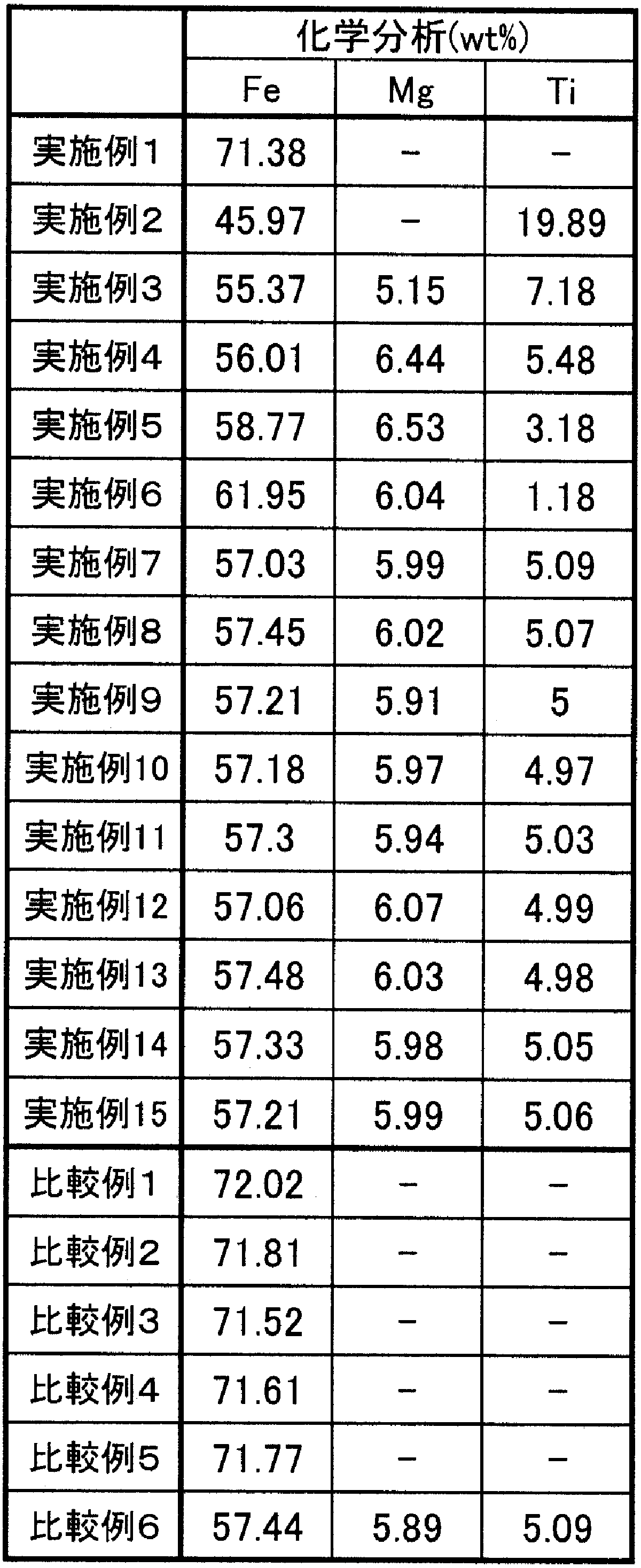
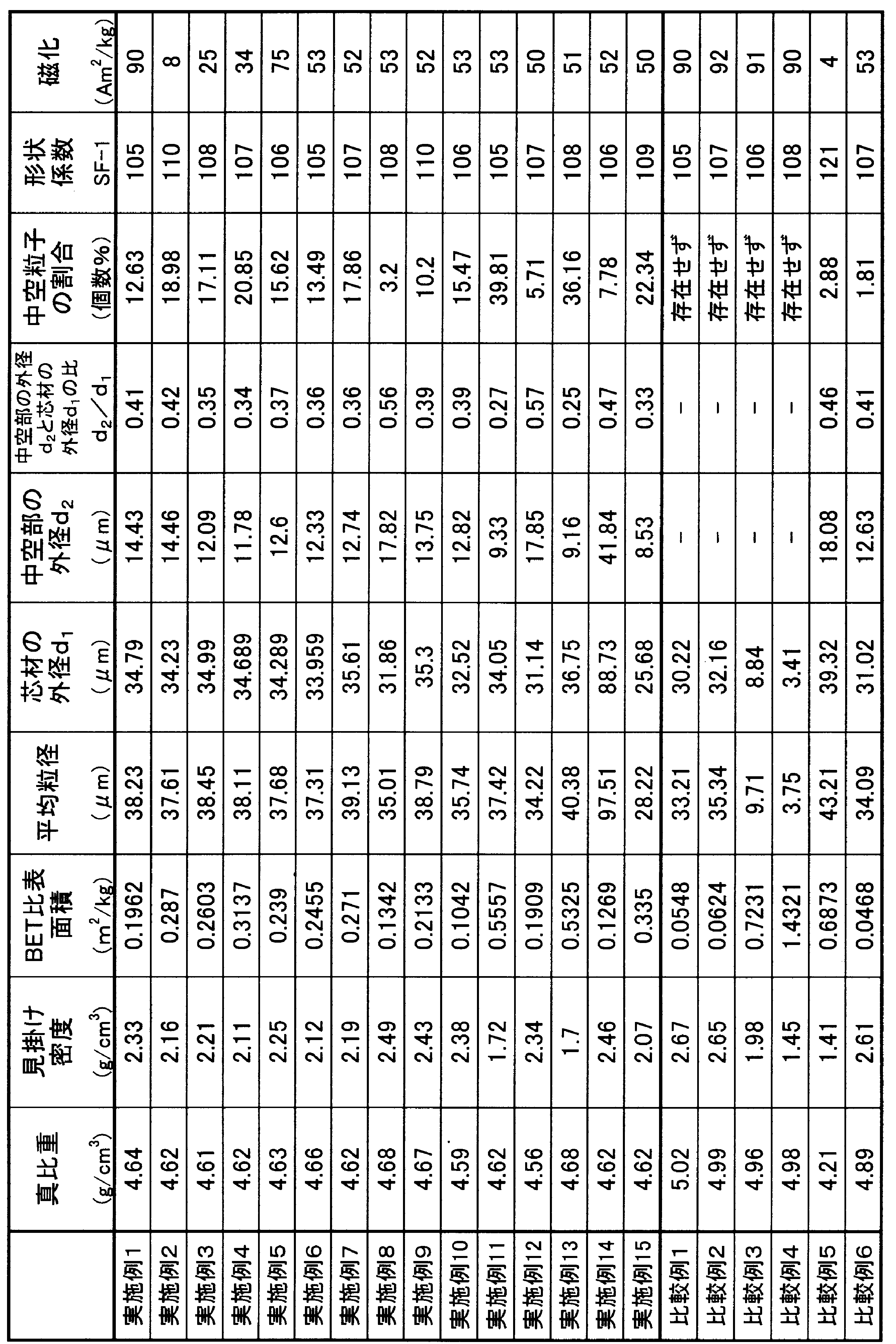
表3に示されるように、実施例1~15においては中空粒子を含有する芯材粒子を得ることが出来たが、鉄源をFeOOHでないものに変えた比較例1及び2では中空粒子を含有する芯材粒子は得られなかった。比較例3はバインダー量が少なく、溶射工程において中空粒子を維持するだけの炭酸ガス及び水蒸気が得られず中空粒子を含有する芯材粒子を得られなかった。比較例4はバインダー量が多く、溶射工程においての炭酸ガス及び水蒸気の生成量が多く中空部が膨張しすぎて破裂し、その破片が球状化し、中空粒子を含有する芯材粒子は得られなかった。比較例5は原料の供給速度が速く、溶射工程で十分は熱を与えることが出来なかったため中空粒子は生成したもののその含有率が少ないだけでなく、原料のバインダー成分だけが除去された粒子が大量に混入し、キャリア芯材として使えないものとなった。比較例6は溶射工程で過剰に熱を与えられ炭酸ガスや水蒸気が一度に粒子の中空部から抜けることで中空粒子は生成したもののその含有率が少なく従来の中空粒子を含有しない芯材粒子と変わらない結果となった。
本発明に係る電子写真現像剤用キャリア芯材及びキャリアは、真球状で、強度に優れ、かつ真密度及び/又は見掛け密度を制御できる。また、本発明の製造方法によって、上記キャリア芯材及びキャリアを好適に生産できる。そして、上記キャリアを用いた電子写真現像剤は現像器におけるトナーとの攪拌において、トナーに対するストレスを軽減することができる。
従って、本発明は、特に高画質の要求されるフルカラー機並びに画像維持の信頼性及び耐久性の要求される高速機の分野に広く使用可能である。
Claims (13)
- 鉄の含有量が36~78重量%の中空の粒子を3~100個数%含有することを特徴とする電子写真現像剤用キャリア芯材。
- 平均粒径が20~150μmである請求項1記載の電子写真現像剤用キャリア芯材。
- 真比重が2.5~4.75g/cm3である請求項1又は2に記載の電子写真現像剤用キャリア芯材。
- 見掛け密度が1.5~2.6g/cm3である請求項1、2又は3記載の電子写真現像剤用キャリア芯材。
- 磁化が5~95Am2/kg(emu/g)である請求項1~4のいずれかに記載の電子写真現像剤用キャリア芯材。
- 芯材の外径(平均粒径)をd1、芯材内部に存在する中空部の外径をd2とした時に0.10<d2/d1<0.90である請求項1~5のいずれかに記載の電子写真現像剤用キャリア芯材。
- 請求項1~6のいずれかに記載のキャリア芯材の表面に樹脂を被覆してなる電子写真現像剤用キャリア。
- キャリア芯材原料をバインダーと共に調製して得られた造粒物を、大気中で溶射してフェライト化し、次いで急冷凝固することを特徴とする電子現像剤用キャリア芯材の製造方法。
- 上記造粒物の見掛け密度が0.4~1.0g/cm3である請求項8記載の電子現像剤用キャリア芯材の製造方法。
- 上記キャリア芯材原料の鉄成分原料としてFeOOHを用いる請求項8又は9記載の電子現像剤用キャリア芯材の製造方法。
- 上記造粒物中のバインダーの含有量が固形分換算で0.8~3.5重量%である請求項8、9又は10記載の電子現像剤用キャリア芯材の製造方法。
- 請求項8~11のいずれかの製造方法によって得られキャリア芯材の表面に樹脂を被覆することを特徴とする電子現像剤用キャリアの製造方法。
- 請求項7記載のキャリアとトナーとからなる電子写真現像剤。
Priority Applications (2)
| Application Number | Priority Date | Filing Date | Title |
|---|---|---|---|
| EP09728593A EP2267550A4 (en) | 2008-03-31 | 2009-02-27 | CARRIER CORE FOR ELECTROPHOTOGRAPHIC DEVELOPER AND METHOD FOR PRODUCING THE SAME, CARRIER AND METHOD FOR PRODUCING SAME, AND ELECTROPHOTOGRAPHIC REVELER |
| US12/921,408 US20110013948A1 (en) | 2008-03-31 | 2009-02-27 | Core material of carrier for electrophotographic developer and method for manufacturing the core material, carrier and method for manufacturing the carrier, and electrophotographic developer using the carrier |
Applications Claiming Priority (2)
| Application Number | Priority Date | Filing Date | Title |
|---|---|---|---|
| JP2008090669A JP5152649B2 (ja) | 2008-03-31 | 2008-03-31 | 電子写真現像剤用キャリア芯材及びその製造方法、キャリア及びその製造方法並びに該キャリアを用いた電子写真現像剤 |
| JP2008-090669 | 2008-03-31 |
Publications (1)
| Publication Number | Publication Date |
|---|---|
| WO2009122832A1 true WO2009122832A1 (ja) | 2009-10-08 |
Family
ID=41135228
Family Applications (1)
| Application Number | Title | Priority Date | Filing Date |
|---|---|---|---|
| PCT/JP2009/053676 WO2009122832A1 (ja) | 2008-03-31 | 2009-02-27 | 電子写真現像剤用キャリア芯材及びその製造方法、キャリア及びその製造方法並びに該キャリアを用いた電子写真現像剤 |
Country Status (4)
| Country | Link |
|---|---|
| US (1) | US20110013948A1 (ja) |
| EP (1) | EP2267550A4 (ja) |
| JP (1) | JP5152649B2 (ja) |
| WO (1) | WO2009122832A1 (ja) |
Cited By (1)
| Publication number | Priority date | Publication date | Assignee | Title |
|---|---|---|---|---|
| CN106715334A (zh) * | 2014-09-19 | 2017-05-24 | 保德科技股份有限公司 | 纳米尺寸的圆球状铁氧体粒子以及其制造方法 |
Families Citing this family (12)
| Publication number | Priority date | Publication date | Assignee | Title |
|---|---|---|---|---|
| JP5522446B2 (ja) * | 2010-01-28 | 2014-06-18 | パウダーテック株式会社 | 電子写真現像剤用フェライトキャリア芯材、フェライトキャリア及び該フェライトキャリアを用いた電子写真現像剤 |
| JP2011227452A (ja) * | 2010-03-30 | 2011-11-10 | Powdertech Co Ltd | 電子写真現像剤用フェライトキャリア芯材、フェライトキャリア及びこれらの製造方法、並びに該フェライトキャリアを用いた電子写真現像剤 |
| JP5488910B2 (ja) | 2010-06-30 | 2014-05-14 | パウダーテック株式会社 | 電子写真現像剤用フェライトキャリア芯材及びフェライトキャリア、並びに該フェライトキャリアを用いた電子写真現像剤 |
| JP5115617B2 (ja) * | 2010-10-29 | 2013-01-09 | 富士ゼロックス株式会社 | 画像形成装置、プロセスカートリッジ、及び画像形成方法 |
| JP2012215858A (ja) | 2011-03-31 | 2012-11-08 | Powdertech Co Ltd | 電子写真現像剤用樹脂被覆キャリア及び該樹脂被覆キャリアを用いた電子写真現像剤 |
| JP5895528B2 (ja) * | 2011-12-28 | 2016-03-30 | パウダーテック株式会社 | 電子写真現像剤用フェライトキャリア芯材、フェライトキャリア及びこれらの製造方法、並びに該フェライトキャリアを用いた電子写真現像剤 |
| JP5870448B2 (ja) * | 2011-12-28 | 2016-03-01 | パウダーテック株式会社 | 電子写真現像剤用フェライトキャリア芯材、フェライトキャリア及びこれらの製造方法、並びに該フェライトキャリアを用いた電子写真現像剤 |
| JP6163652B2 (ja) * | 2012-01-13 | 2017-07-19 | パウダーテック株式会社 | 電子写真現像剤用多孔質フェライト芯材、樹脂被覆フェライトキャリア及び該フェライトキャリアを用いた電子写真現像剤 |
| JP6089333B2 (ja) | 2013-03-21 | 2017-03-08 | パウダーテック株式会社 | 電子写真現像剤用樹脂充填型フェライトキャリア芯材及びフェライトキャリア、並びに該フェライトキャリアを用いた電子写真現像剤 |
| JP6061423B2 (ja) * | 2013-03-29 | 2017-01-18 | Dowaエレクトロニクス株式会社 | キャリア芯材及びそれを用いた電子写真現像用キャリア及び電子写真用現像剤 |
| JP6163963B2 (ja) * | 2013-08-23 | 2017-07-19 | コニカミノルタ株式会社 | 静電荷像現像用二成分現像剤、及びその製造方法 |
| JP6515406B2 (ja) | 2015-01-27 | 2019-05-22 | パウダーテック株式会社 | キャリア及び該キャリアを用いた電子写真現像剤 |
Citations (11)
| Publication number | Priority date | Publication date | Assignee | Title |
|---|---|---|---|---|
| JPS57177160A (en) * | 1981-04-24 | 1982-10-30 | Nec Corp | Developer for electrophotography |
| JPS5823032A (ja) * | 1981-08-04 | 1983-02-10 | Hitachi Metals Ltd | 電子写真用フエライトキヤリヤ−粒子 |
| JPS617851A (ja) * | 1984-06-22 | 1986-01-14 | Hitachi Metals Ltd | フエライトキヤリアの製造方法 |
| JPS6250839A (ja) | 1985-08-30 | 1987-03-05 | Dowa Teppun Kogyo Kk | 電子写真現像剤用フエライトキヤリヤの製造方法 |
| JPH0689046A (ja) * | 1992-09-08 | 1994-03-29 | Hitachi Metals Ltd | 静電荷像現像用磁性粒子の製造方法 |
| JPH07237923A (ja) | 1994-01-07 | 1995-09-12 | Japan Synthetic Rubber Co Ltd | フェライト含有中空粒子 |
| JP2005029437A (ja) | 2003-07-08 | 2005-02-03 | Yazaki Corp | フェライト中空粒子の製造方法 |
| JP2005091486A (ja) * | 2003-09-12 | 2005-04-07 | Canon Inc | 二成分系現像剤及び現像装置 |
| JP2005345675A (ja) * | 2004-06-02 | 2005-12-15 | Matsushita Electric Ind Co Ltd | 電子写真現像剤用キャリア及び電子写真現像剤 |
| JP2007034249A (ja) | 2005-06-22 | 2007-02-08 | Dowa Holdings Co Ltd | 電子写真現像用キャリア芯材、電子写真現像用キャリアおよびその製造方法、並びに電子写真現像剤 |
| WO2007063933A1 (ja) | 2005-11-30 | 2007-06-07 | Powdertech Co., Ltd. | 電子写真現像剤用樹脂コートフェライトキャリア及びその製造方法、並びに該樹脂コートフェライトキャリアを用いた電子写真現像剤 |
Family Cites Families (4)
| Publication number | Priority date | Publication date | Assignee | Title |
|---|---|---|---|---|
| JP4001606B2 (ja) * | 2005-05-31 | 2007-10-31 | パウダーテック株式会社 | 樹脂充填型キャリア及び該キャリアを用いた電子写真現像剤 |
| CN102081317B (zh) * | 2005-09-29 | 2015-03-04 | 同和电子科技有限公司 | 电子照相显影剂用载体芯材、电子照相显影剂用载体及其制造方法、以及电子照相显影剂 |
| JP5333882B2 (ja) * | 2006-09-14 | 2013-11-06 | 株式会社リコー | 電子写真用現像剤 |
| JP5334251B2 (ja) * | 2009-02-04 | 2013-11-06 | パウダーテック株式会社 | 電子写真現像剤用キャリア芯材、キャリア及びこれらの製造方法、並びに該キャリアを用いた電子写真現像剤 |
-
2008
- 2008-03-31 JP JP2008090669A patent/JP5152649B2/ja active Active
-
2009
- 2009-02-27 WO PCT/JP2009/053676 patent/WO2009122832A1/ja active Application Filing
- 2009-02-27 EP EP09728593A patent/EP2267550A4/en not_active Withdrawn
- 2009-02-27 US US12/921,408 patent/US20110013948A1/en not_active Abandoned
Patent Citations (11)
| Publication number | Priority date | Publication date | Assignee | Title |
|---|---|---|---|---|
| JPS57177160A (en) * | 1981-04-24 | 1982-10-30 | Nec Corp | Developer for electrophotography |
| JPS5823032A (ja) * | 1981-08-04 | 1983-02-10 | Hitachi Metals Ltd | 電子写真用フエライトキヤリヤ−粒子 |
| JPS617851A (ja) * | 1984-06-22 | 1986-01-14 | Hitachi Metals Ltd | フエライトキヤリアの製造方法 |
| JPS6250839A (ja) | 1985-08-30 | 1987-03-05 | Dowa Teppun Kogyo Kk | 電子写真現像剤用フエライトキヤリヤの製造方法 |
| JPH0689046A (ja) * | 1992-09-08 | 1994-03-29 | Hitachi Metals Ltd | 静電荷像現像用磁性粒子の製造方法 |
| JPH07237923A (ja) | 1994-01-07 | 1995-09-12 | Japan Synthetic Rubber Co Ltd | フェライト含有中空粒子 |
| JP2005029437A (ja) | 2003-07-08 | 2005-02-03 | Yazaki Corp | フェライト中空粒子の製造方法 |
| JP2005091486A (ja) * | 2003-09-12 | 2005-04-07 | Canon Inc | 二成分系現像剤及び現像装置 |
| JP2005345675A (ja) * | 2004-06-02 | 2005-12-15 | Matsushita Electric Ind Co Ltd | 電子写真現像剤用キャリア及び電子写真現像剤 |
| JP2007034249A (ja) | 2005-06-22 | 2007-02-08 | Dowa Holdings Co Ltd | 電子写真現像用キャリア芯材、電子写真現像用キャリアおよびその製造方法、並びに電子写真現像剤 |
| WO2007063933A1 (ja) | 2005-11-30 | 2007-06-07 | Powdertech Co., Ltd. | 電子写真現像剤用樹脂コートフェライトキャリア及びその製造方法、並びに該樹脂コートフェライトキャリアを用いた電子写真現像剤 |
Non-Patent Citations (1)
| Title |
|---|
| See also references of EP2267550A4 * |
Cited By (2)
| Publication number | Priority date | Publication date | Assignee | Title |
|---|---|---|---|---|
| CN106715334A (zh) * | 2014-09-19 | 2017-05-24 | 保德科技股份有限公司 | 纳米尺寸的圆球状铁氧体粒子以及其制造方法 |
| CN106715334B (zh) * | 2014-09-19 | 2019-08-16 | 保德科技股份有限公司 | 纳米尺寸的圆球状铁氧体粒子以及其制造方法 |
Also Published As
| Publication number | Publication date |
|---|---|
| JP2009244572A (ja) | 2009-10-22 |
| JP5152649B2 (ja) | 2013-02-27 |
| EP2267550A4 (en) | 2011-07-27 |
| EP2267550A1 (en) | 2010-12-29 |
| US20110013948A1 (en) | 2011-01-20 |
Similar Documents
| Publication | Publication Date | Title |
|---|---|---|
| JP5152649B2 (ja) | 電子写真現像剤用キャリア芯材及びその製造方法、キャリア及びその製造方法並びに該キャリアを用いた電子写真現像剤 | |
| JP4781015B2 (ja) | 電子写真用フェライトキャリア芯材、電子写真用フェライトキャリア及びこれらの製造方法、並びに該フェライトキャリアを用いた電子写真用現像剤 | |
| JP5166881B2 (ja) | 電子写真現像剤用樹脂コートフェライトキャリア及びその製造方法、並びに該樹脂コートフェライトキャリアを用いた電子写真現像剤 | |
| JP5334251B2 (ja) | 電子写真現像剤用キャリア芯材、キャリア及びこれらの製造方法、並びに該キャリアを用いた電子写真現像剤 | |
| JP5281251B2 (ja) | 電子写真現像剤用樹脂コートフェライトキャリア及び該樹脂コートフェライトキャリアを用いた電子写真現像剤 | |
| JP5488910B2 (ja) | 電子写真現像剤用フェライトキャリア芯材及びフェライトキャリア、並びに該フェライトキャリアを用いた電子写真現像剤 | |
| JP5692766B1 (ja) | 外殻構造を有するフェライト粒子を用いた電子写真現像剤用フェライトキャリア芯材及びフェライトキャリア、並びに該フェライトキャリアを用いた電子写真現像剤 | |
| JP5360701B2 (ja) | 電子写真現像剤用キャリア芯材、キャリア及びこれらの製造方法、並びに該キャリアを用いた電子写真現像剤 | |
| JP4646781B2 (ja) | 電子写真現像剤用樹脂被覆フェライトキャリア及びその製造方法、並びに該樹脂被覆フェライトキャリアを用いた電子写真現像剤 | |
| JP2009258595A (ja) | 電子写真現像剤用樹脂充填型キャリア及び該樹脂充填型キャリアを用いた電子写真現像剤 | |
| JP2011154288A (ja) | 電子写真現像剤用フェライトキャリア芯材、フェライトキャリア及び該フェライトキャリアを用いた電子写真現像剤 | |
| JP2011008298A (ja) | 電子写真現像剤用樹脂被覆フェライトキャリア及びその製造方法、並びに該樹脂被覆フェライトキャリアを用いた電子写真現像剤 | |
| JP2009175666A (ja) | 電子写真現像剤用樹脂充填型キャリア及び該樹脂充填型キャリアを用いた電子写真現像剤 | |
| JP2009244837A (ja) | 電子写真現像剤用樹脂充填型キャリア及び該樹脂充填型キャリアを用いた電子写真現像剤 | |
| JP5850331B2 (ja) | 電子写真現像剤用フェライトキャリア芯材及びフェライトキャリア、並びに該フェライトキャリアを用いた電子写真現像剤 | |
| JP5541598B2 (ja) | 電子写真現像剤用フェライトキャリア芯材及び電子写真現像剤用フェライトキャリア、並びに該電子写真現像剤用フェライトキャリアを用いた電子写真現像剤 | |
| JP5995048B2 (ja) | 電子写真現像剤用フェライトキャリア芯材、フェライトキャリア及びこれらの製造方法、並びに該フェライトキャリアを用いた電子写真現像剤 | |
| JP5240901B2 (ja) | 電子写真現像剤用キャリア芯材、キャリア及び該キャリアを用いた電子写真現像剤 | |
| JP6569173B2 (ja) | 外殻構造を有するフェライト粒子 | |
| JP2015190995A (ja) | 電子写真現像剤用フェライトキャリア芯材、フェライトキャリア及び該フェライトキャリアを用いた電子写真現像剤 | |
| JP5348587B2 (ja) | 電子写真現像剤用樹脂充填型キャリア及び該樹脂充填型キャリアを用いた電子写真現像剤 | |
| JP4567600B2 (ja) | 電子写真現像剤用樹脂被覆キャリア及びその製造方法、並びに該樹脂被覆キャリアを用いた電子写真現像剤 | |
| JP2007148452A (ja) | 不定形フェライトキャリア及び該フェライトキャリアを用いた電子写真現像剤 |
Legal Events
| Date | Code | Title | Description |
|---|---|---|---|
| 121 | Ep: the epo has been informed by wipo that ep was designated in this application |
Ref document number: 09728593 Country of ref document: EP Kind code of ref document: A1 |
|
| WWE | Wipo information: entry into national phase |
Ref document number: 12921408 Country of ref document: US |
|
| NENP | Non-entry into the national phase |
Ref country code: DE |
|
| WWE | Wipo information: entry into national phase |
Ref document number: 2009728593 Country of ref document: EP |