WO2009122775A1 - Capteur de position rotatif - Google Patents
Capteur de position rotatif Download PDFInfo
- Publication number
- WO2009122775A1 WO2009122775A1 PCT/JP2009/052188 JP2009052188W WO2009122775A1 WO 2009122775 A1 WO2009122775 A1 WO 2009122775A1 JP 2009052188 W JP2009052188 W JP 2009052188W WO 2009122775 A1 WO2009122775 A1 WO 2009122775A1
- Authority
- WO
- WIPO (PCT)
- Prior art keywords
- housing
- axis
- annular
- rotational position
- rotor
- Prior art date
Links
Images


Classifications
-
- G—PHYSICS
- G01—MEASURING; TESTING
- G01D—MEASURING NOT SPECIALLY ADAPTED FOR A SPECIFIC VARIABLE; ARRANGEMENTS FOR MEASURING TWO OR MORE VARIABLES NOT COVERED IN A SINGLE OTHER SUBCLASS; TARIFF METERING APPARATUS; MEASURING OR TESTING NOT OTHERWISE PROVIDED FOR
- G01D5/00—Mechanical means for transferring the output of a sensing member; Means for converting the output of a sensing member to another variable where the form or nature of the sensing member does not constrain the means for converting; Transducers not specially adapted for a specific variable
- G01D5/12—Mechanical means for transferring the output of a sensing member; Means for converting the output of a sensing member to another variable where the form or nature of the sensing member does not constrain the means for converting; Transducers not specially adapted for a specific variable using electric or magnetic means
- G01D5/14—Mechanical means for transferring the output of a sensing member; Means for converting the output of a sensing member to another variable where the form or nature of the sensing member does not constrain the means for converting; Transducers not specially adapted for a specific variable using electric or magnetic means influencing the magnitude of a current or voltage
- G01D5/142—Mechanical means for transferring the output of a sensing member; Means for converting the output of a sensing member to another variable where the form or nature of the sensing member does not constrain the means for converting; Transducers not specially adapted for a specific variable using electric or magnetic means influencing the magnitude of a current or voltage using Hall-effect devices
- G01D5/145—Mechanical means for transferring the output of a sensing member; Means for converting the output of a sensing member to another variable where the form or nature of the sensing member does not constrain the means for converting; Transducers not specially adapted for a specific variable using electric or magnetic means influencing the magnitude of a current or voltage using Hall-effect devices influenced by the relative movement between the Hall device and magnetic fields
-
- G—PHYSICS
- G01—MEASURING; TESTING
- G01D—MEASURING NOT SPECIALLY ADAPTED FOR A SPECIFIC VARIABLE; ARRANGEMENTS FOR MEASURING TWO OR MORE VARIABLES NOT COVERED IN A SINGLE OTHER SUBCLASS; TARIFF METERING APPARATUS; MEASURING OR TESTING NOT OTHERWISE PROVIDED FOR
- G01D11/00—Component parts of measuring arrangements not specially adapted for a specific variable
- G01D11/24—Housings ; Casings for instruments
- G01D11/245—Housings for sensors
-
- G—PHYSICS
- G01—MEASURING; TESTING
- G01D—MEASURING NOT SPECIALLY ADAPTED FOR A SPECIFIC VARIABLE; ARRANGEMENTS FOR MEASURING TWO OR MORE VARIABLES NOT COVERED IN A SINGLE OTHER SUBCLASS; TARIFF METERING APPARATUS; MEASURING OR TESTING NOT OTHERWISE PROVIDED FOR
- G01D5/00—Mechanical means for transferring the output of a sensing member; Means for converting the output of a sensing member to another variable where the form or nature of the sensing member does not constrain the means for converting; Transducers not specially adapted for a specific variable
- G01D5/12—Mechanical means for transferring the output of a sensing member; Means for converting the output of a sensing member to another variable where the form or nature of the sensing member does not constrain the means for converting; Transducers not specially adapted for a specific variable using electric or magnetic means
- G01D5/244—Mechanical means for transferring the output of a sensing member; Means for converting the output of a sensing member to another variable where the form or nature of the sensing member does not constrain the means for converting; Transducers not specially adapted for a specific variable using electric or magnetic means influencing characteristics of pulses or pulse trains; generating pulses or pulse trains
- G01D5/24428—Error prevention
- G01D5/24433—Error prevention by mechanical means
- G01D5/24442—Error prevention by mechanical means by mounting means
-
- G—PHYSICS
- G01—MEASURING; TESTING
- G01D—MEASURING NOT SPECIALLY ADAPTED FOR A SPECIFIC VARIABLE; ARRANGEMENTS FOR MEASURING TWO OR MORE VARIABLES NOT COVERED IN A SINGLE OTHER SUBCLASS; TARIFF METERING APPARATUS; MEASURING OR TESTING NOT OTHERWISE PROVIDED FOR
- G01D2205/00—Indexing scheme relating to details of means for transferring or converting the output of a sensing member
- G01D2205/60—Means for precisely aligning or centering the disk of a rotary encoder, e.g. fitting jigs
Definitions
- the present invention relates to a rotational position sensor that detects an angular position of a rotating body, and in particular, a contact that detects a rotational angle of a throttle shaft of an engine mounted on a vehicle or the like, a depression angle of an accelerator pedal that swings around a predetermined axis, and the like.
- the present invention relates to a rotary position sensor of the type or non-contact type.
- Conventional rotational position sensors include a housing having a radial bearing hole and a thrust bearing end face, a rotor having a shaft portion rotatably inserted into the bearing bore of the housing and abutted against the bearing end face.
- a return spring that rotates and urges the rotor to a predetermined rotational angle position, and a fixed terminal for detection disposed so as to face a disk-shaped flange portion formed radially outside the shaft portion of the rotor in the housing.
- Rotal position sensors include a housing having a radial bearing hole, a shaft having a shaft portion rotatably inserted into the bearing hole of the housing, and a radially outer side than the shaft portion of the shaft in the housing.
- a ring-shaped movable magnet fixed to a disk-shaped flange formed on a plurality of members, a plurality of magnetic plates fixed to the housing so as to sandwich the movable magnet in the axial direction of the shaft, a Hall element arranged between the magnetic plates, etc.
- the shaft rotates, the relative angular position of the movable magnet (N pole and S pole) of the shaft, the magnetic plate fixed to the housing, and the Hall element changes, and the hall changes according to the change in the angular position.
- a device that detects a rotational angle position of a shaft by detecting a change in magnetic flux flowing through an element is known (for example, Patent Document 2). Irradiation).
- the shaft portion of the rotor or shaft is rotatably supported by the bearing hole of the housing, and on the radially outer side of the shaft portion, a movable contact for detection and a fixed terminal or a movable magnet and Since the Hall element is arranged, the center of rotation of the rotor or shaft fluctuates to be positioned at a predetermined position due to wear on the outer peripheral surface of the shaft portion or the inner peripheral surface of the bearing hole.
- the relative positional relationship between the fixed terminal and the relative position between the movable magnet and the Hall element changes, and the rotational position of the rotor or shaft may not be detected with high accuracy.
- the present invention has been made in view of the circumstances of the above-described conventional apparatus.
- the object of the present invention is to provide a rotating body such as a rotor or a shaft whose rotational position is detected over time due to wear or the like in its bearing area. Even if a change occurs, it can be supported so that the centering action can be obtained automatically, and the rotational angle position of the rotating body can be detected with high accuracy, and the axis of the rotating body (rotation center line)
- An object of the present invention is to provide a rotational position sensor capable of simplifying the structure, reducing the size, and the like by effectively using the region located above as a part placement location.
- the rotational position sensor of the present invention is provided in the rotating body so as to detect a rotation angle position of the rotating body, a housing having a bearing portion, a rotating body that is rotatably supported around the predetermined axis by the bearing portion.
- a movable sensor element and a sensor unit including a fixed sensor element provided in the housing, wherein the rotating body has an annular contact surface centered on the axis, and the bearing portion is centered on the axis and annularly contacted.
- An annular bearing surface that receives the contact surface, and at least one of the annular abutment surface and the annular bearing surface is formed as an annular tapered surface that defines a part of an imaginary conical surface having an apex on the axis; It has become.
- the rotating body and the bearing portion are supported so that the annular contact surface comes into contact with the annular bearing surface and is rotatable about a predetermined axis, and at least one of the annular contact surface and the annular bearing surface Is formed in an annular tapered surface that defines a part of a virtual conical surface having a vertex on a predetermined axis, so that the rotating body is always positioned on the axis by automatic alignment. Therefore, even if the bearing area changes with time, such as wear, it is possible to prevent the displacement of the movable sensor element of the rotating unit constituting the sensor unit from the axis of the fixed sensor element of the housing, and the rotational angle position of the rotating body. Can be detected with high accuracy.
- the housing may include a guide member formed separately, and the guide member may have an annular bearing surface.
- the annular bearing surface by forming the annular bearing surface with the guide member formed separately from the housing, a dedicated material excellent in wear resistance different from the material of the housing can be used. Therefore, the overall cost can be reduced while ensuring the wear resistance of the bearing region.
- the said structure WHEREIN The structure currently formed so that the cyclic
- the rotating body may have a connection hole that connects a shaft that is disposed outside the housing and detects a rotation angle. According to this configuration, it is possible to detect the angular position only by connecting the shaft that should originally detect the rotational angular position to the connection hole of the rotating body. Therefore, this rotational position sensor can be handled as an independent and highly versatile module product, and this rotational position sensor can be applied to all objects including the shaft to be detected.
- the rotating body has a cylindrical portion centered on the axis, and a disk portion that is integrally formed on one end side of the cylindrical portion and defines an annular contact surface
- the housing has an annular bearing surface
- a housing cover including a cylindrical bearing surface that is detachably formed with respect to the housing body and rotatably supports the cylindrical portion.
- the annular cover is brought into contact with the annular bearing surface, the rotating body is incorporated into the housing body, the cylindrical portion is fitted into the cylindrical bearing surface, and the housing cover is coupled to the housing body.
- the rotating body can be easily incorporated into the housing.
- the housing is provided with a return spring that returns the rotating body to a predetermined angular position.
- the return spring is disposed around the cylindrical portion and between the disc portion and the housing cover, and is attached in the axial direction.
- a configuration that is a torsion spring that exerts an urging force and an urging force around the axis can be adopted.
- the rotating body is assembled in the housing body, and the torsion spring as the return spring is fitted into the cylindrical portion of the rotating body so as to contact the disk portion of the rotating body, and the housing cover is attached to the housing from above.
- the rotating body and the return spring can be easily incorporated into the housing, and rattling of the rotating body in the thrust direction can be reliably prevented.
- the housing cover may be configured to be snap-fit coupled to the housing body. According to this configuration, the housing cover can be connected to the housing body with a simple structure, and the structure can be simplified, the number of parts can be reduced, and the like.
- the movable sensor element of the sensor unit includes a magnet formed in a disk shape, the magnet is embedded in a central region through which the axis of the rotating body passes, and the fixed sensor element of the sensor unit is emitted from the magnet.
- a configuration may be employed in which a magnetic sensing element that can pass magnetic lines of force and sense a change in magnetic flux density is disposed in a central region through which the axis of the housing passes.
- a non-contact type magnetic sensor including a magnet and a magnetic sensing element can be used as the sensor unit, and the sensor unit is disposed in a central region through which the axis of the rotating body passes ( In other words, since it is possible to arrange components centering on the axis), the structure can be simplified, downsized, and the like.
- the rotational position sensor having the above-described configuration, even if a rotating body such as a rotor or a shaft whose rotational position is detected undergoes a change over time due to wear or the like in its bearing area, the alignment operation is automatically obtained. Therefore, the rotation angle position of the rotating body can be detected with high accuracy, and the region located on the axis (rotation center line) of the rotating body is used as the component placement location. By making effective use, the structure can be simplified, downsized, and the like.
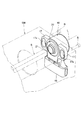
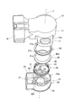
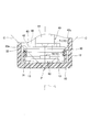
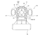
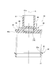
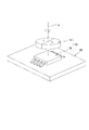
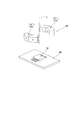
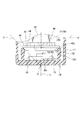
- FIG. 1 is an external perspective view showing an embodiment of a rotational position sensor according to the present invention. It is a disassembled perspective view which shows one Embodiment of the rotational position sensor which concerns on this invention. It is a disassembled perspective view which shows one Embodiment of the rotational position sensor which concerns on this invention. It is sectional drawing which shows one Embodiment of the rotational position sensor which concerns on this invention. It is the fragmentary sectional view which expanded a part of rotation position sensor shown in FIG. It is a top view which shows the housing main body which makes a part of rotational position sensor which concerns on this invention. It is a side view which shows the housing main body which makes a part of rotational position sensor which concerns on this invention.
- FIG. 5 is a cross-sectional view showing a rotor (rotary body) and a guide member that constitute a part of the rotational position sensor, showing another embodiment of the rotational position sensor according to the present invention.
- FIG. 14 is a cross-sectional view illustrating a rotor (rotary body) and a guide member that constitute a part of the rotational position sensor according to still another embodiment of the rotational position sensor according to the present invention.
- FIG. 5 is a partial cross-sectional view showing a further embodiment of the rotational position sensor according to the present invention and enlarging a part of the rotational position sensor.
- this rotational position sensor is attached to, for example, an engine throttle device SM and is applied to detect the rotational angle position of the throttle shaft S. That is, as shown in FIGS. 1 and 2, this rotational position sensor is disposed rotatably in a housing body 10 and a housing cover 20 as a housing, a guide member 30 fixed to the housing body 10, and the housing.
- a sensor unit 70 including a fixed sensor element provided, a terminal 80 provided on the housing body 10 and the like are provided.
- the housing main body 10 has a cylindrical portion 11 defining a cylindrical accommodating recess 11a closed at one end, and has a center on the same axis L in the cylindrical portion 11.
- the fitting portion 12 that is formed as described above to fit the guide member 30 described later, the four clamping pieces 13 and the one positioning protrusion 14 that are formed inside the annular fitting portion 12 to fix the circuit board 60, the housing A fitting groove 15 to which the cover 20 is fitted and joined, a connector part 16 that protrudes in the radial direction from the cylindrical part 11 and accommodates the terminal 80 therein, two mounting flange parts 17 that protrude in the radial direction from the cylindrical part 11, etc. I have.
- the fitting part 12 fits a guide member 30 to be described later and is integrally fixed to the housing main body 10.
- the arcuate part 12a and the arcuate part 12a are arranged in the radial direction. It is formed so as to define an extending parallel portion 12b.
- the clamping piece 13 and the positioning projection 14 clamp the edge of the circuit board 60 with the four clamping pieces 13 while aligning with the positioning projection 14 when the circuit board 60 is arranged and fixed in the accommodating recess 11a. And snap-fit to secure.
- the fitting groove 15 is formed so as to be integrally fixed to the housing main body 10 by fitting a fitting portion 22 (latching piece 22a thereof) of the housing cover 20 to be described later and snap-fitting them together.
- the mounting flange portion 17 has an arc-shaped bolt hole 17a, and is formed so as to be fastened and fixed to the side surface of the throttle device SM while adjusting the angular position using the bolt B as shown in FIG. Has been.
- the housing cover 20 is detachably formed with respect to the housing body 10 by snap-fit coupling. As shown in FIGS. 1 to 4, the housing cover 20 is rotatably supported through a cylindrical portion 41 of a rotor 40 described later. A hole 21, a fitting portion 22 fitted in the fitting groove 15 of the housing body 10, a spring receiving surface 25 that receives one end of the return spring 50 in the direction of the axis L, and a hook that latches one end 51 of the return spring 50.
- the stop projection 26 and two stoppers 27 for restricting the rotation angle range of the rotor 40 are provided.
- the through-hole 21 is formed to have an inner diameter dimension that forms a minute gap with the outer peripheral surface of the cylindrical portion 41 in order to smoothly rotate the cylindrical portion 41 of the rotor 40 and prevent dust and the like from entering.
- the fitting portion 22 has three hooking pieces 22 a extending in a direction parallel to the axis L, and is fitted into the fitting groove 15 of the housing body 10 and snap fit. It is formed to bond.
- the spring receiving surface 25 cooperates with a disk portion 42 of the rotor 40 to be described later, and compresses the return spring 50 by a predetermined amount in the direction of the axis L, so that one end side of the return spring 50 is It is configured to be seated and received.
- the latching protrusion 26 is formed so as to latch one end 51 of the return spring 50 so as to generate an urging force to return to the initial position when the return spring 50 is twisted about the axis L.
- the two stoppers 27 protrude from the spring receiving surface 25 in the direction of the axis L, and in contact with a contact piece 46 of the rotor 40 described later in the rotational direction around the axis L, It is formed so as to regulate the rotation range.
- the guide member 30 is integrally formed with a coupling portion 31 that is fitted to the fitting portion 12 of the housing body 10, and the annular bearing.
- An annular bearing portion 32 that defines a surface 32a is provided.
- the connecting portion 31 is formed so as to define an arc-shaped portion 31a and two parallel portions 31b extending in the radial direction from the arc-shaped portion 31a, and the guide member 30 rotates around the axis L.
- the fitting portion 12 is fitted so as to restrict and position the center on the axis L.
- the bearing portion 32 abuts on the end surface of the fitting portion 12 and is formed in an annular shape protruding in the radial direction from the coupling portion 31 so as to be positioned in the axis L direction, and rotates the rotor 40 in the inner edge region.
- An annular bearing surface 32a is movably supported.
- the annular bearing surface 32a defines a part of a virtual conical surface C having an apex P on the axis L as shown in FIG. 5 so as to rotatably support an annular contact surface 42a of the rotor 40 described later. That is, it is formed as an annular tapered surface that defines the outer peripheral surface of the truncated cone.
- the guide member 30 is formed separately from the housing main body 10 and is then fitted and fixed to the fitting portion 12 of the housing main body 10. As described above, the guide member 30 that is separately formed and then fixed to the housing body 10 is adopted as the bearing portion that rotatably supports the rotor 40, and the annular bearing surface 32 a is formed on the guide member 30. Thus, a dedicated material excellent in wear resistance different from the material of the housing (housing main body 10) can be used, and the overall cost can be reduced while ensuring the wear resistance of the bearing region. .
- the rotor 40 includes a cylindrical portion 41 centered on the axis L, and a disk that is integrally formed on one end side of the cylindrical portion 41 and defines an annular contact surface 42 a.
- the cylindrical portion 41 defines a connection hole 41a that is disposed outside the housing (the housing main body 10 and the housing cover 20) and connects the shaft S whose rotation angle is detected so as to rotate integrally. Yes.
- the circular plate portion 42 defines an annular contact surface 42 a that rotatably contacts the annular bearing surface 32 a of the guide member 30.
- the annular contact surface 42a is formed so as to define a part of the virtual conical surface C having the apex P on the axis L, that is, as an annular tapered surface that defines the outer peripheral surface of the truncated cone. Has been. As shown in FIG.
- the spring receiving surface 43 cooperates with the spring receiving surface 25 of the housing cover 20, and compresses the return spring 50 by a predetermined amount in the direction of the axis L. It is configured to be seated and received.
- the annular positioning portion 44 is formed in an arc shape having a center coaxially with the axis L around the cylindrical portion 41, and the return spring 50 moves in the radial direction on the disc portion 42 (spring receiving surface 43 thereof). It is formed so as to restrict it.
- the latching groove 45 is formed to latch the other end 52 of the return spring 50 so as to generate an urging force that returns to the initial position when the return spring 50 is twisted about the axis L. .
- the rotor 40 includes a magnet 71 (as a movable sensor element) of the sensor unit 70 embedded in a central region through which the axis L passes.
- the rotor 40 is accommodated in the housing (the housing body 10 and the housing cover 20) by the annular bearing surface 32a of the guide member 30 in which the annular contact surface 42a of the disc portion 42 is fixed to the housing body 10.
- the cylindrical portion 41 is rotatably supported by the through hole 21 of the housing cover 20. Therefore, at the time of assembly, the annular cover part 42a is brought into contact with the annular bearing surface 32a, the rotor 40 is incorporated into the housing body 10, and the cylindrical part 41 is fitted into the through hole 21, so that the housing cover 20 is fitted into the housing body.
- the rotor 40 can be easily incorporated into the housing by being snap-fit coupled to the housing 10.
- the rotor 40 since the rotor 40 has a connection hole 41a that connects the shaft S that is arranged outside the housing and whose rotation angle is detected, the shaft S that should originally detect the rotation angle position is connected to the connection hole 41a. Only the angular position can be detected. Therefore, this rotational position sensor can be handled as an independent and highly versatile module product, and this rotational position sensor can be applied to all objects including the shaft S to be detected.
- the return spring 50 is a torsion spring that is incorporated in a state compressed by a predetermined amount in the direction of the axis L and exerts a rotational biasing force around the axis L, and one end side of which is a cylinder of the rotor 40.
- the portion 41 is seated on the spring receiving surface 25 of the housing cover 20, one end 51 is hooked on the hooking protrusion 26 of the housing cover 20, and the other end is spring receiving around the annular positioning portion 44 of the rotor 40. While being seated on the surface 43, the other end 52 is latched in the latching groove 45 of the rotor 40.
- the return spring 50 incorporates the rotor 40 into the housing body 10, contacts the spring receiving surface 43 (of the disc portion 42) of the rotor 40, and engages the other end 52 with the retaining groove 45. Then, the housing cover 20 is fitted to the housing body 10 so as to be fitted around the cylindrical portion 41 of the rotor 40 and the one end portion 51 is hooked on the hooking projection 26 from above, so that the rotor 40 and The return spring 50 can be easily incorporated into the housing.
- the return spring 50 exerts a rotational biasing force so as to return the rotor 40 to a predetermined angular position (initial position), and also biases the rotor 40 so as to prevent rattling of the rotor 40 in the axis L direction (thrust direction). It has come to exert.
- the circuit board 60 is formed in a substantially rectangular shape, a positioning hole 61 in a part thereof, and a magnetic sensing element 72 as a fixed sensor element to be described later mounted on the upper surface thereof. And other mounted electronic components (not shown).
- the circuit board 60 is positioned at a predetermined position in the housing recess 11 with the positioning projections 14 of the housing body 10 being fitted into the positioning holes 61 and the edges thereof being sandwiched between the four clamping pieces 13 of the housing body 10. Has been fixed.
- the sensor unit 70 includes a magnet 71 as a movable sensor element embedded in the rotor 40, a magnetic sensing element 72 as a fixed sensor element mounted on the circuit board 60, and the like. Is formed. As shown in FIG. 7, the magnet 71 is embedded in a central region through which the axis L of the rotor 40 passes, and as shown in FIG. 8, the magnet 71 is formed in a disk shape having a predetermined thickness, and approximately half is N The other half of the pole is magnetized to the S pole. As shown in FIGS. 2, 5, and 8, the magnetic sensing element 72 is disposed through a circuit board 60 in a central region through which the axis L of the housing body 10 passes, and changes in relative angle with the magnet 71.
- the resistance value changes due to (that is, a change in magnetic field). That is, the magnetic sensing element 72 detects the angular position of the rotor 40 by sensing a change in the incident angle of the magnetic flux.
- this sensor unit 70 there is a certain allowable range (ie, insensitivity) with respect to the deviation in the direction of the axis L in the relative positional relationship between the magnet 71 and the magnetic sensing element 72, and the sensor unit 70 is perpendicular to the axis L. It is necessary to manage the direction deviation (center deviation) with high accuracy (that is, it is sensitive).
- the magnet 71 embedded in the rotor 40 and the magnetic sensing element 72 on the circuit board 60 fixed to the housing body 10 need to be positioned (centered) with high accuracy in a plane perpendicular to the axis L. is there.
- the annular contact surface 42a of the rotor 40 comes into contact with the annular bearing surface 32a included in the housing body 10 and is supported rotatably about the axis L.
- the annular contact surface 42a and the annular bearing surface 32a are supported by the axis L. Since the rotor 40 is positioned on the virtual conical surface C having the apex P on the upper side, the rotor 40 is always positioned on the axis L by the automatic alignment action.
- the positional deviation with respect to L can be prevented, and the rotational angle position of the rotor 40 can be detected with high accuracy.
- the movable sensor element (magnet 71) and the fixed sensor element (magnetic sensing element 72) of the sensor unit 70 are arranged in a central region through which the axis L of the rotor 40 passes, that is, the component arrangement centered on the axis L. Therefore, simplification of the structure, size reduction, and the like can be achieved. Further, since the fixed sensor element (magnetic sensing element 72) of the sensor unit 70 is provided on the circuit board 60 that is detachable from the housing body 10, only the circuit board 60 is fitted into the housing (housing body 10). Thus, the fixed sensor element (such as the magnetic sensing element 72) of the sensor unit 70 can be fixed to the housing, and assembly can be easily performed as a whole.
- a non-contact type sensor composed of a magnet 71 and a magnetic sensing element 72 is shown as the sensor unit 70, but the present invention is not limited to this, and a magnetoresistive element (MR) is used as the magnetic sensing element 72.
- MR magnetoresistive element
- a contact sensor that includes a movable contact as a movable sensor element and a wiring terminal as a fixed sensor element and detects a rotation angle in accordance with a change in resistance value may be employed.
- FIG. 9 is a sectional view showing another embodiment of the rotational position sensor according to the present invention, in which the shape of the annular bearing surface 32a of the guide member 30 in the embodiment shown in FIG. 7 is changed. Therefore, the same components as those of the above-described embodiment are denoted by the same reference numerals and description thereof is omitted.
- the guide member 30 ′ is formed integrally with the coupling portion 31 that is fitted to the fitting portion 12 of the housing body 10, and the annular bearing surface 32 a ′.
- An annular bearing portion 32 is defined.
- the annular bearing surface 32 a ′ is formed so as to have a cross section curved in a convex shape toward the annular contact surface 42 a.
- the rotor 40 is supported so as to be rotatable about the axis L, with the annular contact surface 42a contacting the annular bearing surface 32a 'included in the housing body 10. Since the annular contact surface 42a and the annular bearing surface 32a 'are positioned on the virtual conical surface C having the apex P on the axis L, the rotor 40 is always positioned on the axis L by the automatic alignment action. . Therefore, even if the bearing region changes with time, such as wear, the axis L of the movable sensor element (magnet 71) of the rotor 40 and the fixed sensor element (magnetic sensing element 72) of the housing constituting the sensor unit 70 can be reduced.
- the rotor 40 ′ includes a cylindrical portion 41, a disc portion 42, a spring receiving surface 43, an annular positioning portion 44, a latching groove 45, a contact piece 46, etc., as shown in FIG. .
- the annular contact surface 42 a ′ is formed to have a cross section that is curved in a convex shape toward the annular bearing surface 32 a of the guide member 30.
- the rotor 40 ′ is supported so as to be rotatable about the axis L with the annular contact surface 42 a ′ contacting the annular bearing surface 32 a included in the housing body 10. Since the annular contact surface 42a ′ and the annular bearing surface 32a are located on the virtual conical surface C having the apex P on the axis L, the rotor 40 ′ is always positioned on the axis L by the automatic alignment action. Yes.
- the annular contact surface 42a ' is formed in a convexly curved cross-sectional shape, the annular contact surface 42a' and the annular bearing surface 32a are secured while ensuring the self-aligning action of the rotor 40 '. The sliding resistance between them can be reduced, and the rotor 40 'can be rotated more smoothly.
- FIG. 11 shows still another embodiment of the rotational position sensor according to the present invention, in which the shape of the magnet 71 of the sensor unit 70 in the embodiment shown in FIG. 8 is changed. Therefore, the same components as those of the above-described embodiment are denoted by the same reference numerals and description thereof is omitted.
- the sensor unit 70 ′ includes a magnet 71 ′ as a movable sensor element embedded in the rotor 40, a magnetic sensing element 72 as a fixed sensor element mounted on the circuit board 60, and the like. It is formed by. As shown in FIG.
- the magnet 71 ′ is composed of two divided magnets 71 a ′ and 71 b ′, and is embedded in a central region through which the axis L of the rotor 40 passes. As shown in FIG. 11, the magnets 71 a ′ and 71 b ′ are formed in an arc shape having a predetermined thickness, and approximately half are magnetized to the N pole and the remaining approximately half are magnetized to the S pole in the circumferential direction. .
- the movable sensor element (magnet 71 ′) and the fixed sensor element (magnetic sensing element 72) of the sensor unit 70 ′ are arranged in the central region through which the axis L of the rotor 40 passes, That is, since the components can be arranged around the axis L, simplification of the structure, size reduction, and the like can be achieved.
- the fixed sensor element (magnetic sensing element 72) of the sensor unit 70 ' is provided on the circuit board 60 that is detachable from the housing body 10, the circuit board 60 is fitted into the housing (housing body 10).
- the fixed sensor element (such as the magnetic sensing element 72) of the sensor unit 70 ' can be fixed to the housing, and assembly can be easily performed as a whole.
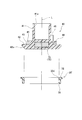
- FIG. 12 shows still another embodiment of the rotational position sensor according to the present invention.
- the guide members 30 and 30 ′ are eliminated, and the bearing portion 12 ′ is mounted on the housing body 10 ′.
- symbol is attached
- the annular bearing surface 12a ′ defines a part of a virtual conical surface C having an apex P on the axis L, as shown in FIG. 12, to rotatably support the annular contact surface 42a of the rotor 40. That is, it is formed in a tapered surface shape that defines the outer peripheral surface of the truncated cone.
- the rotor 40 is supported so as to be rotatable around the axis L with the annular contact surface 42a contacting the annular bearing surface 12a 'included in the housing body 10'. Since the annular contact surface 42a and the annular bearing surface 12a 'are positioned on the virtual conical surface C having the apex P on the axis L, the rotor 40 is always positioned on the axis L by the automatic alignment action. Yes. Therefore, even if the bearing region changes with time, such as wear, the axis L of the movable sensor element (magnet 71) of the rotor 40 and the fixed sensor element (magnetic sensing element 72) of the housing constituting the sensor unit 70 can be reduced.
- the bearing portion 12 ′ is formed integrally with the housing body 10 ′, the number of parts of the housing body 10 ′ can be reduced, and the structure can be simplified.
- the rotor 40 accommodated in the housing (the housing body 10 and the housing cover 20) is shown as the rotating body.
- the rotor 40 is not limited to this, and is inserted directly from the outside to the inside of the housing.
- the shaft S may be used.
- the throttle device SM is shown as an object to which the rotational position sensor is applied.
- the throttle device SM is not limited to this, and is applied to the accelerator pedal device to detect the depression degree of the accelerator pedal.
- the present invention may be applied to an apparatus that needs to detect other rotation angles.
- the housing divided into the housing main body 10 and the housing cover 20 is shown.
- the housing is not limited to this, as long as the rotor 40, the return spring 50, and the like can be assembled. An integral housing may be employed.
- the torsion spring is shown as the return spring 50.
- the present invention is not limited to this, and the return spring 50 acts to urge the rotor 40 around the axis L and urge it in the direction of the axis L. If so, other springs may be employed.
- the return spring 50 is included has been described in the above embodiment, the present invention is not limited to this, and the present invention has a configuration in which the return spring 50 is eliminated from the rotational position sensor and provided on the external object side. May be adopted.
- the rotational position sensor of the present invention automatically aligns a rotating body such as a rotor or a shaft whose rotational position is detected even if a change with time due to wear or the like of the bearing area occurs. Any object that can be supported so that the action can be obtained, and can be simplified, downsized, etc., so that the rotational angle position of the rotating body needs to be detected with high accuracy.
- the present invention is not limited to an apparatus related to an engine, but is useful for other machine-related apparatus or an electric-related apparatus.
Abstract
Le capteur de position rotatif selon la présente invention est doté d’une unité de capteur (70) comprenant un corps rotatif (40) supporté de sorte à tourner librement autour d’une ligne axiale prescrite (L) par une partie support de logement (10, 20), un composant de capteur mobile (71) disposé sur le corps rotatif afin de détecter une position d’angle rotatif du corps rotatif et un composant de capteur fixe (72) disposé sur les logements. Le corps rotatif (40) a une surface de butée annulaire effilée (42a) qui délimite une partie de surface de cône virtuelle (C) avec un pic (P) sur la ligne axiale (L) et la partie support a une surface de support annulaire effilée (32a) supportant la surface de butée annulaire pour qu’elle tourne librement sur la surface de cône virtuelle (C). Ainsi, le corps rotatif peut toujours être positionné sur la ligne axiale en raison d’un effet d’auto-alignement. Par conséquent, même lorsqu’un changement tel que l’usure a lieu avec le passage du temps dans une région de support, la position d’angle rotatif pour le corps rotatif peut être détectée à une précision élevée.
Priority Applications (3)
| Application Number | Priority Date | Filing Date | Title |
|---|---|---|---|
| CN200980110810XA CN101981414B (zh) | 2008-03-31 | 2009-02-10 | 旋转位置传感器 |
| EP09728745.2A EP2264408A4 (fr) | 2008-03-31 | 2009-02-10 | Capteur de position rotatif |
| US12/923,615 US8400144B2 (en) | 2008-03-31 | 2010-09-29 | Rotational position sensor having axially central sensor unit |
Applications Claiming Priority (2)
| Application Number | Priority Date | Filing Date | Title |
|---|---|---|---|
| JP2008-089905 | 2008-03-31 | ||
| JP2008089905A JP5301864B2 (ja) | 2008-03-31 | 2008-03-31 | 回転位置センサ |
Related Child Applications (1)
| Application Number | Title | Priority Date | Filing Date |
|---|---|---|---|
| US12/923,615 Continuation US8400144B2 (en) | 2008-03-31 | 2010-09-29 | Rotational position sensor having axially central sensor unit |
Publications (1)
| Publication Number | Publication Date |
|---|---|
| WO2009122775A1 true WO2009122775A1 (fr) | 2009-10-08 |
Family
ID=41135174
Family Applications (1)
| Application Number | Title | Priority Date | Filing Date |
|---|---|---|---|
| PCT/JP2009/052188 WO2009122775A1 (fr) | 2008-03-31 | 2009-02-10 | Capteur de position rotatif |
Country Status (5)
| Country | Link |
|---|---|
| US (1) | US8400144B2 (fr) |
| EP (1) | EP2264408A4 (fr) |
| JP (1) | JP5301864B2 (fr) |
| CN (1) | CN101981414B (fr) |
| WO (1) | WO2009122775A1 (fr) |
Cited By (1)
| Publication number | Priority date | Publication date | Assignee | Title |
|---|---|---|---|---|
| CN114216393A (zh) * | 2022-02-21 | 2022-03-22 | 泉州昆泰芯微电子科技有限公司 | 旋转角度检测装置、旋钮、学习用具及娱乐用具 |
Families Citing this family (24)
| Publication number | Priority date | Publication date | Assignee | Title |
|---|---|---|---|---|
| JP5384267B2 (ja) * | 2009-09-16 | 2014-01-08 | 株式会社ミクニ | 回転角検出装置 |
| US9188462B2 (en) | 2010-06-30 | 2015-11-17 | Ntn Corporation | Rotation sensor-equipped bearing |
| JP5484221B2 (ja) * | 2010-06-30 | 2014-05-07 | Ntn株式会社 | 回転検出機能付き滑り軸受装置 |
| JP5535018B2 (ja) * | 2010-09-17 | 2014-07-02 | Ntn株式会社 | 回転センサ付軸受 |
| US8390276B2 (en) * | 2010-09-27 | 2013-03-05 | Bourns Incorporated | Target magnet assembly for a sensor used with a steering gear |
| DE102011002254A1 (de) * | 2011-04-22 | 2012-10-25 | Schaeffler Technologies AG & Co. KG | Positionsgeber insbesondere zur Bestimmung der Position eines Läufers eines planaren Direktantriebs |
| DE102011081637A1 (de) * | 2011-08-26 | 2013-02-28 | Zf Friedrichshafen Ag | Führungsabschnitt eines Gehäuses für einen Sensor, Gehäuse für einen Sensor sowie Sensor, insbesondere für ein Fahrzeuggetriebe und Verfahren zum Herstellen eines Gehäuses für einen Sensor, insbesondere für ein Fahrzeuggetriebe |
| US10365953B2 (en) * | 2012-05-01 | 2019-07-30 | Red Hat, Inc. | Tracking and utilizing facts about a node of a multi-tenant cloud hosting environment |
| DE102012105969A1 (de) * | 2012-07-04 | 2014-01-09 | Hella Kgaa Hueck & Co. | Drehwinkelsensor |
| CN102881065B (zh) * | 2012-10-10 | 2015-04-08 | 红门智能科技股份有限公司 | 转动式车辆出入管理装置 |
| JP6190157B2 (ja) * | 2013-05-16 | 2017-08-30 | アズビル株式会社 | 回転角度検出器 |
| JP5987877B2 (ja) * | 2013-10-04 | 2016-09-07 | 株式会社デンソー | 電子スロットル |
| JP6584424B2 (ja) * | 2014-03-26 | 2019-10-02 | シェフラー テクノロジーズ アー・ゲー ウント コー. カー・ゲーSchaeffler Technologies AG & Co. KG | センサ磁石アッセンブリ |
| KR102221836B1 (ko) * | 2014-08-13 | 2021-03-03 | 현대모비스 주식회사 | 차량용 램프 |
| GB2535556B (en) | 2015-07-14 | 2017-06-28 | Longvale Ltd | Electrical Process Control Sensor Assemblies |
| CN105532177B (zh) * | 2016-02-22 | 2017-12-26 | 农业部南京农业机械化研究所 | 一种纵轴流收割机滚筒转速检测装置 |
| CN107796298B (zh) * | 2016-09-05 | 2024-04-19 | 泰科电子(上海)有限公司 | 角度传感器 |
| JP6741611B2 (ja) * | 2017-02-20 | 2020-08-19 | 株式会社不二工機 | 電動弁 |
| DE102017117759A1 (de) * | 2017-08-04 | 2019-02-07 | Mimatic Gmbh | Sensornachrüstsatz |
| JP6913625B2 (ja) * | 2017-12-22 | 2021-08-04 | 三菱重工コンプレッサ株式会社 | ジャーナル軸受、回転機械、及びジャーナル軸受製造方法 |
| DE102019106288B3 (de) * | 2019-03-12 | 2020-03-05 | Sick Stegmann Gmbh | Drehgeber |
| DE102020100319A1 (de) * | 2020-01-09 | 2021-07-15 | HELLA GmbH & Co. KGaA | Drehwinkelsensor zur Bestimmung eines Drehwinkels und/oder eines Drehmoments |
| US20230258519A1 (en) * | 2022-02-14 | 2023-08-17 | KSR IP Holdings, LLC | Pedal assembly having force sensing |
| DE102022103731A1 (de) * | 2022-02-17 | 2023-08-17 | HELLA GmbH & Co. KGaA | Drehwinkelsensoreinheit, Deckel für ein Gehäuse einer Drehwinkelsensoreinheit und Verfahren zum Herstellen einer Drehwinkelsensoreinheit |
Citations (8)
| Publication number | Priority date | Publication date | Assignee | Title |
|---|---|---|---|---|
| JPS6423114A (en) * | 1987-07-20 | 1989-01-25 | Agency Ind Science Techn | Magnetic rotary sensor |
| JPH04115120A (ja) * | 1990-09-05 | 1992-04-16 | Alps Electric Co Ltd | 磁気式ロータリエンコーダの組立方法 |
| JPH11201713A (ja) * | 1998-01-16 | 1999-07-30 | Unisia Jecs Corp | 回動角検出装置 |
| JP2000107288A (ja) * | 1998-10-05 | 2000-04-18 | Terumo Corp | シリンジポンプ |
| JP2001124508A (ja) | 1999-10-22 | 2001-05-11 | Aisan Ind Co Ltd | ロータリポジションセンサ |
| JP2002250343A (ja) * | 2001-02-21 | 2002-09-06 | Minebea Co Ltd | 特殊軸受装置 |
| JP2003269992A (ja) * | 2002-03-12 | 2003-09-25 | Alps Electric Co Ltd | ロータリポジションセンサ |
| JP2004150905A (ja) | 2002-10-30 | 2004-05-27 | Hitachi Ltd | 非接触式回転位置センサ及び非接触式回転位置センサを有する電子制御スロットル弁装置 |
Family Cites Families (6)
| Publication number | Priority date | Publication date | Assignee | Title |
|---|---|---|---|---|
| JP3587695B2 (ja) * | 1998-09-08 | 2004-11-10 | アルプス電気株式会社 | 回転型センサ |
| US6445178B1 (en) * | 1999-02-24 | 2002-09-03 | Donnelly Corporation | Vehicular magnetic displacement sensor for determining an offset in the output of the sensor |
| JP4174222B2 (ja) * | 2002-03-07 | 2008-10-29 | アルプス電気株式会社 | 回転型センサ |
| JP4039665B2 (ja) * | 2002-10-04 | 2008-01-30 | タカラベルモント株式会社 | エステ機器における施術器具ホルダー装置 |
| JP4524099B2 (ja) * | 2003-12-19 | 2010-08-11 | オリンパス株式会社 | 内視鏡装置 |
| JP2009180499A (ja) * | 2006-03-17 | 2009-08-13 | Murata Mfg Co Ltd | 角度検出装置 |
-
2008
- 2008-03-31 JP JP2008089905A patent/JP5301864B2/ja not_active Expired - Fee Related
-
2009
- 2009-02-10 CN CN200980110810XA patent/CN101981414B/zh not_active Expired - Fee Related
- 2009-02-10 EP EP09728745.2A patent/EP2264408A4/fr not_active Withdrawn
- 2009-02-10 WO PCT/JP2009/052188 patent/WO2009122775A1/fr active Application Filing
-
2010
- 2010-09-29 US US12/923,615 patent/US8400144B2/en not_active Expired - Fee Related
Patent Citations (8)
| Publication number | Priority date | Publication date | Assignee | Title |
|---|---|---|---|---|
| JPS6423114A (en) * | 1987-07-20 | 1989-01-25 | Agency Ind Science Techn | Magnetic rotary sensor |
| JPH04115120A (ja) * | 1990-09-05 | 1992-04-16 | Alps Electric Co Ltd | 磁気式ロータリエンコーダの組立方法 |
| JPH11201713A (ja) * | 1998-01-16 | 1999-07-30 | Unisia Jecs Corp | 回動角検出装置 |
| JP2000107288A (ja) * | 1998-10-05 | 2000-04-18 | Terumo Corp | シリンジポンプ |
| JP2001124508A (ja) | 1999-10-22 | 2001-05-11 | Aisan Ind Co Ltd | ロータリポジションセンサ |
| JP2002250343A (ja) * | 2001-02-21 | 2002-09-06 | Minebea Co Ltd | 特殊軸受装置 |
| JP2003269992A (ja) * | 2002-03-12 | 2003-09-25 | Alps Electric Co Ltd | ロータリポジションセンサ |
| JP2004150905A (ja) | 2002-10-30 | 2004-05-27 | Hitachi Ltd | 非接触式回転位置センサ及び非接触式回転位置センサを有する電子制御スロットル弁装置 |
Non-Patent Citations (1)
| Title |
|---|
| See also references of EP2264408A4 |
Cited By (2)
| Publication number | Priority date | Publication date | Assignee | Title |
|---|---|---|---|---|
| CN114216393A (zh) * | 2022-02-21 | 2022-03-22 | 泉州昆泰芯微电子科技有限公司 | 旋转角度检测装置、旋钮、学习用具及娱乐用具 |
| CN114216393B (zh) * | 2022-02-21 | 2022-05-17 | 泉州昆泰芯微电子科技有限公司 | 旋转角度检测装置、旋钮、学习用具及娱乐用具 |
Also Published As
| Publication number | Publication date |
|---|---|
| JP5301864B2 (ja) | 2013-09-25 |
| EP2264408A4 (fr) | 2014-09-17 |
| CN101981414A (zh) | 2011-02-23 |
| CN101981414B (zh) | 2012-08-08 |
| JP2009244039A (ja) | 2009-10-22 |
| US20110018529A1 (en) | 2011-01-27 |
| EP2264408A1 (fr) | 2010-12-22 |
| US8400144B2 (en) | 2013-03-19 |
Similar Documents
| Publication | Publication Date | Title |
|---|---|---|
| JP5301864B2 (ja) | 回転位置センサ | |
| WO2012063599A1 (fr) | Capteur d'angle sans contact | |
| JP2013190337A (ja) | 回転角度検出装置 | |
| JP2009229395A (ja) | 回転センサユニット | |
| JP3496581B2 (ja) | 回転角検出装置 | |
| US6836111B2 (en) | Sensor assembly with a universal sensor module for sensing angular position of an object | |
| JP2024026598A (ja) | アブソリュートエンコーダ | |
| EP1850094A2 (fr) | Capteur de rotation | |
| JP5400571B2 (ja) | 回転シャフトに組み立てるための角度位置センサ | |
| JP2005345170A (ja) | 回転角度検出装置 | |
| JP2008267966A (ja) | マグネットユニット及びアクセルペダル装置 | |
| JP5192926B2 (ja) | 回転角検出装置 | |
| JP2001133212A (ja) | 非接触式回転角センサ及びセンサコア | |
| US11578994B2 (en) | Fixing structure | |
| US8497675B2 (en) | Angle detector | |
| JP2013244842A (ja) | アクセルペダル装置 | |
| JP2007085743A (ja) | 非接触回転変位センサ | |
| JP2001141412A (ja) | 非接触式回転角センサ及びセンサコア | |
| JP2002286497A (ja) | 変位センサ | |
| JP2023154041A (ja) | 回転角度検出装置 | |
| JP6451252B2 (ja) | 回転角検出装置 | |
| JP2004155377A (ja) | アクセルペダル装置 | |
| JP2004155374A (ja) | アクセルペダル装置 | |
| JP2013076715A (ja) | 被読取板固定用部材、被読取板固定用組立体、及び信号検出装置、並びにロータリーエンコーダ | |
| JP2003139228A (ja) | 自動変速機のポジションセンサ |
Legal Events
| Date | Code | Title | Description |
|---|---|---|---|
| WWE | Wipo information: entry into national phase |
Ref document number: 200980110810.X Country of ref document: CN |
|
| 121 | Ep: the epo has been informed by wipo that ep was designated in this application |
Ref document number: 09728745 Country of ref document: EP Kind code of ref document: A1 |
|
| REEP | Request for entry into the european phase |
Ref document number: 2009728745 Country of ref document: EP |
|
| WWE | Wipo information: entry into national phase |
Ref document number: 2009728745 Country of ref document: EP |
|
| NENP | Non-entry into the national phase |
Ref country code: DE |