WO2009122600A1 - 発進装置 - Google Patents
発進装置 Download PDFInfo
- Publication number
- WO2009122600A1 WO2009122600A1 PCT/JP2008/065356 JP2008065356W WO2009122600A1 WO 2009122600 A1 WO2009122600 A1 WO 2009122600A1 JP 2008065356 W JP2008065356 W JP 2008065356W WO 2009122600 A1 WO2009122600 A1 WO 2009122600A1
- Authority
- WO
- WIPO (PCT)
- Prior art keywords
- oil passage
- input shaft
- radial
- hydraulic
- oil
- Prior art date
- Legal status (The legal status is an assumption and is not a legal conclusion. Google has not performed a legal analysis and makes no representation as to the accuracy of the status listed.)
- Ceased
Links
Images


Classifications
-
- F—MECHANICAL ENGINEERING; LIGHTING; HEATING; WEAPONS; BLASTING
- F16—ENGINEERING ELEMENTS AND UNITS; GENERAL MEASURES FOR PRODUCING AND MAINTAINING EFFECTIVE FUNCTIONING OF MACHINES OR INSTALLATIONS; THERMAL INSULATION IN GENERAL
- F16D—COUPLINGS FOR TRANSMITTING ROTATION; CLUTCHES; BRAKES
- F16D25/00—Fluid-actuated clutches
- F16D25/12—Details not specific to one of the before-mentioned types
- F16D25/123—Details not specific to one of the before-mentioned types in view of cooling and lubrication
-
- F—MECHANICAL ENGINEERING; LIGHTING; HEATING; WEAPONS; BLASTING
- F16—ENGINEERING ELEMENTS AND UNITS; GENERAL MEASURES FOR PRODUCING AND MAINTAINING EFFECTIVE FUNCTIONING OF MACHINES OR INSTALLATIONS; THERMAL INSULATION IN GENERAL
- F16D—COUPLINGS FOR TRANSMITTING ROTATION; CLUTCHES; BRAKES
- F16D25/00—Fluid-actuated clutches
- F16D25/06—Fluid-actuated clutches in which the fluid actuates a piston incorporated in, i.e. rotating with the clutch
- F16D25/062—Fluid-actuated clutches in which the fluid actuates a piston incorporated in, i.e. rotating with the clutch the clutch having friction surfaces
- F16D25/063—Fluid-actuated clutches in which the fluid actuates a piston incorporated in, i.e. rotating with the clutch the clutch having friction surfaces with clutch members exclusively moving axially
- F16D25/0635—Fluid-actuated clutches in which the fluid actuates a piston incorporated in, i.e. rotating with the clutch the clutch having friction surfaces with clutch members exclusively moving axially with flat friction surfaces, e.g. discs
- F16D25/0638—Fluid-actuated clutches in which the fluid actuates a piston incorporated in, i.e. rotating with the clutch the clutch having friction surfaces with clutch members exclusively moving axially with flat friction surfaces, e.g. discs with more than two discs, e.g. multiple lamellae
-
- F—MECHANICAL ENGINEERING; LIGHTING; HEATING; WEAPONS; BLASTING
- F16—ENGINEERING ELEMENTS AND UNITS; GENERAL MEASURES FOR PRODUCING AND MAINTAINING EFFECTIVE FUNCTIONING OF MACHINES OR INSTALLATIONS; THERMAL INSULATION IN GENERAL
- F16H—GEARING
- F16H61/00—Control functions within control units of change-speed- or reversing-gearings for conveying rotary motion ; Control of exclusively fluid gearing, friction gearing, gearings with endless flexible members or other particular types of gearing
- F16H2061/0046—Details of fluid supply channels, e.g. within shafts, for supplying friction devices or transmission actuators with control fluid
-
- F—MECHANICAL ENGINEERING; LIGHTING; HEATING; WEAPONS; BLASTING
- F16—ENGINEERING ELEMENTS AND UNITS; GENERAL MEASURES FOR PRODUCING AND MAINTAINING EFFECTIVE FUNCTIONING OF MACHINES OR INSTALLATIONS; THERMAL INSULATION IN GENERAL
- F16H—GEARING
- F16H61/00—Control functions within control units of change-speed- or reversing-gearings for conveying rotary motion ; Control of exclusively fluid gearing, friction gearing, gearings with endless flexible members or other particular types of gearing
- F16H61/0003—Arrangement or mounting of elements of the control apparatus, e.g. valve assemblies or snapfittings of valves; Arrangements of the control unit on or in the transmission gearbox
- F16H61/0009—Hydraulic control units for transmission control, e.g. assembly of valve plates or valve units
Definitions
- the present invention relates to a starting device in a vehicle having an automatic transmission.
- This launcher has an oil-tight housing (input side member) connected to the output shaft of the engine, and in the housing, the input shaft of the transmission mechanism is normally inserted by spline connection.
- a turbine hub integrally rotatably coupled to a shaft, and a clutch mechanism for mechanically connecting and directly connecting the turbine hub and the housing by clutch operation.
- a thrust bearing that regulates the axial movement of the turbine hub is interposed between the inner surface of the housing and the axial front and rear end surfaces of the turbine hub. Then, an oil passage for supplying lubricating oil to each component such as the thrust bearing and the clutch mechanism, and an oil passage for supplying hydraulic oil for switching the clutch mechanism from the non-engagement state to the engagement state as necessary. are provided so as to form an oil passage structure according to the arrangement location of each part in the housing.
- a hydraulic oil passage for supplying hydraulic oil discharged from an oil pump to a clutch mechanism is provided in the following oil passage structure. That is, in the starting device of Patent Document 1, an axial oil passage portion in which the hydraulic oil passage is bored in the axial direction from the tip end portion of the input shaft of the transmission mechanism, and the tip (front end) of the axial oil passage portion And an oil passage structure including at least a radially extending oil passage extending radially outward so as to penetrate radially outward from the inside of the front cover constituting the front half of the housing and communicate with the oil pressure chamber of the clutch mechanism. doing.
- the lubricating oil path that circulates the lubricating oil discharged from the oil pump so as to circulate around the location of each component such as the thrust bearing and the clutch mechanism is the supply oil path that supplies the lubricating oil into the housing from the oil pump side.
- a return oil passage for returning lubricating oil from the inside of the housing to the oil pump side, and each oil passage is provided in the following oil passage structure.
- the oil passage portion on the upstream side in the supply direction is the inner peripheral surface of the sleeve shaft fitted in the cylindrical portion projecting rearward from the turbine hub and the through hole in which the spline is formed in the turbine hub
- It is constituted by an axial oil passage portion extending in the axial direction so as to reach the front end side in the axial direction of the turbine hub through between the peripheral surface and the outer peripheral surface of the input shaft of the transmission mechanism.
- an oil passage portion on the downstream side of the supply oil passage in the supply direction is a front thrust interposed between the front end (front end) of the axial oil passage portion and the inner surface of the front cover and the axial front end surface of the turbine hub.
- It is constituted by a radial oil passage extending at least radially so as to supply lubricating oil radially outward while lubricating the bearing.
- the return oil passage is a rear thrust bearing in which the oil passage portion on the upstream side in the return direction is interposed between the inner surface of the pump cover constituting the rear half of the housing and the axial rear end surface of the turbine hub It comprises a radial oil passage portion extending at least radially so as to return the lubricating oil radially inward while lubricating. Then, the inner peripheral surface of the cylindrical portion in which the oil passage portion on the downstream side in the return direction of the return oil passage protrudes rearward from the inner peripheral edge portion of the pump cover corresponding to the tip (inner end) of the radial oil passage portion.
- An object of the present invention is to provide a launch device capable of miniaturizing a device by suppressing an increase in axial direction even when a plurality of oil passages including at least radially extending oil passages are provided. It is in.
- the starting device of the present invention has a housing connected to an output shaft of a drive source, and a through hole through which an input shaft of a transmission mechanism can be inserted, and the input shaft
- the output side member is connected integrally rotatably with the input shaft by being inserted from the tip end portion of the input shaft, and the housing and the output side member are directly coupled so as to be able to transmit power by operating the clutch.
- At least one of the supply oil passage and the return oil passage in the lubricating oil passage includes at least a radial oil passage extending radially, and the hydraulic oil passage is at least radially
- the radial oil passage portion in the lubricating oil passage and the radial oil passage portion in the hydraulic oil passage, which extend in the radial oil passage, are offset from each other in the circumferential direction about the axis of the input shaft.
- At least one of the supply oil passage and the return oil passage in the lubricating oil passage includes at least a radial oil passage extending radially, and the hydraulic oil passage is at least radially
- the radial oil passage portion includes an extending radial oil passage portion, and a part of the radial oil passage portion in the lubricating oil passage extends in a direction orthogonal to the axis of the input shaft, while the radial oil in the hydraulic oil passage A part of the passage portion is a part of the radial oil passage portion in the lubricating oil passage, rather than a portion on the radial direction inward side of a portion on the radial direction outward side in a portion of the radial direction oil passage portion.
- the extending direction is inclined so as to be separated from the portion in the axial direction.
- At least one of the supply oil passage and the return oil passage in the lubricating oil passage includes at least a radial oil passage extending radially, and an axial end face of the output side member
- a thrust bearing is interposed between the housing and the inner surface of the housing facing the end face, and a portion of the radial oil passage portion in the lubricating oil passage is a portion of the radial oil passage portion.
- the thrust bearing can be lubricated by flowing lubricating oil.
- the thrust bearing is disposed between the axial end face of the output side member and the inner surface of the housing in order to bear an axial load on the output side member. Therefore, the axial length of the entire device is increased by the axial thickness of the thrust bearing.
- this problem can be solved by applying an oil path configuration in which a portion of the radial oil path portion of the lubricating oil path that lubricates such a thrust bearing partially overlaps the hydraulic oil path in the axial direction. It can respond suitably.
- the hydraulic fluid passage includes an axial fluid passage extending axially along the inside of the input shaft, and a radial fluid passage extending at least radially,
- the radial oil passage portion of the oil passage is configured such that an oil hole is opened at an outer peripheral surface portion of the input shaft facing the inner peripheral surface of the through hole in a state where the output side member is connected to the input shaft.
- the hydraulic fluid passage has a radial oil passage portion formed in the output side member so as to extend at least radially.
- the radial oil passage portion of the hydraulic oil passage is formed on the output side member coupled integrally rotatably with the input shaft. Therefore, when the axial oil passage portion of the hydraulic oil passage communicates with the radial oil passage portion through the oil hole opened from the middle position of the input shaft in the axial direction to the outer peripheral surface portion of the input shaft, the oil of the output side member
- the opening on the inner diameter side of the passage (radial oil passage portion) is disposed so as to always face the oil hole of the input shaft along the radial direction. Therefore, the hydraulic pressure supplied through the axial oil passage portion of the hydraulic oil passage can be responsively supplied to the clutch mechanism at least through the radial oil passage portion of the hydraulic oil passage.
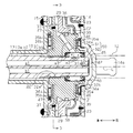
- the longitudinal section of the starting device concerning one embodiment of the present invention.
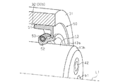
- the principal part expanded sectional view of the starting apparatus of FIG. FIG. 2 is a partial sectional view taken along line 3-3 in FIG. The perspective view which shows the oil seal mounting state of this embodiment.
- FIGS. 1 to 8 an embodiment of a starting device embodying the present invention will be described with reference to FIGS. 1 to 8.
- the front-rear direction indicated by the arrow in FIG.
- the starting device 11 is a device for transmitting the torque of the output shaft 12 of the engine as a drive source to the input shaft 13 of the transmission mechanism, and is connected to the output shaft 12 of the engine
- a housing 16 as an input side member is constituted by the front cover 14 and the pump cover 15 fixed to the outer peripheral end of the front cover 14 by welding.
- a damper device 17 and a start clutch 18 as a clutch mechanism are housed inside the housing 16 and filled with oil and hydraulic fluid and ATF (automatic transmission fluid) as lubricating oil. There is.
- the front cover 14 has a bottomed, substantially cylindrical shape with a closed front side and an open rear side, and an output of the engine at a connecting portion 14 a protruding forward from a substantially central portion of an outer surface (front surface) of the bottom wall thereof.
- the shaft 12 is connected to rotate around the axis L of the input shaft 13 of the transmission mechanism based on the rotational drive of the output shaft 12 of the engine.
- the pump cover 15 has a substantially annular shape that can close the opening on the rear side of the front cover 14, and a cylinder connected to the drive shaft of an oil pump (not shown) as a hydraulic pressure source at its center.
- Support cover 19 is fixed so as to constitute a part of the pump cover 15. That is, the rotation of the output shaft 12 of the engine is transmitted to the oil pump through the front cover 14 and the pump cover 15 (and the support cover 19).
- the damper device 17 includes an annular damper plate 20 connected to the engine side, an annular damper disk 21 connected to the transmission mechanism side, and a torque transmission means for transmitting the rotational force of the damper plate 20 to the damper disk 21. It has 22 and.
- the damper plate 20 is fixed to a rear surface (an inner surface facing the pump cover 15) on the outer peripheral side of the front cover 14, and rotates integrally with the front cover 14.
- the damper disc 21 restricts the axial movement of the transmission mechanism about the axis L of the input shaft 13 by fitting to the cylindrical support member 23 whose inner peripheral edge is fixed to the rear surface of the front cover 14 It is rotatably supported in the closed state.
- the damper disk 21 rotates at a relative angle with respect to the front cover 14 exceeding a predetermined angle, the predetermined position in the circumferential direction is locked to a part of the outer peripheral surface of the support member 23. Further rotation restrictions are to be made.
- the torque transfer means 22 is composed of a plurality of damper springs 24 and an intermediate member 25 interposed between the damper springs 24 so as to elastically connect the damper springs 24 in series.
- Each damper spring 24 has its one end in contact with the damper plate 20 or the damper disk 21 and its other end in contact with the intermediate member 25. Therefore, the rotational drive from the output shaft 12 of the engine transmitted to the damper plate 20 through the front cover 14 is a torque that exerts a damper function as the damper spring 24 and the intermediate member 25 are elastically connected in series. It is transmitted to the damper disc 21 via the transmission means 22.
- the damper disc 21 is restricted in rotation by engagement with the support member 23 so that the relative angle with the front cover 14 does not exceed a predetermined value, the spring length of the damper spring 24 reaches a limit value. It does not shrink.
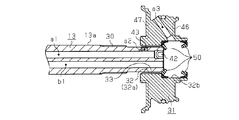
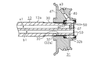
- the input shaft 13 of the transmission mechanism has a spline 30 as an uneven engaged portion on the outer peripheral surface 13a on the base end (rear end) side by a predetermined distance from the front end (front end). It is formed along the front-rear direction. Further, a tapered surface 13b is formed on the periphery of the tip end surface of the input shaft 13 by chamfering so that the diameter decreases toward the tip end.
- the input shaft 13 of this transmission mechanism has an axial length portion from the tip end to the position where the spline 30 is formed penetrating the turbine hub 31 as an output side member.
- the turbine hub 31 is formed to have a cylindrical shape, and a through hole 32 through which the input shaft 13 can be inserted is formed in the axial center thereof.
- the through hole 32 is formed as a small diameter portion 32a having a diameter substantially the same as the diameter of the input shaft 13 from the middle to the rear in the axial direction, and from the axial middle to the front has a diameter larger than the small diameter portion 32a. It is formed as a large diameter portion 32b.
- the turbine hub 31 and the input shaft 13 can be axially moved relative to the spline 30 formed on the outer peripheral surface 13a of the input shaft 13 in the circumferential direction
- the spline 33 is formed as a concavo-convex engaging portion which engages in a relative non-movable manner.
- the spline 33 formed on the inner peripheral surface of the small diameter portion 32 a of the through hole 32 is the input shaft 13.
- the input shaft 13 and the turbine hub 31 are coupled so as to be able to rotate integrally with each other by engaging with the splines 30 formed on the side in a concavo-convex manner.
- a pair of front and rear oil seals 50 are press-fit into the large diameter portion 32b of the through hole 32 of the turbine hub 31 in a state in which the tip end portion of the input shaft 13 is pierced. ing.
- the specific configuration of the oil seal 50 will be described in detail later.
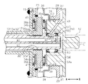
- the turbine hub 31 is coupled to the input shaft 13 of the transmission mechanism in a state where annular thrust bearings 34a and 34b capable of withstanding the load in the thrust direction accompanying the rotation thereof are disposed on both sides in the axial direction. That is, the first thrust bearing 34a is interposed between the rear surface (inner surface) of the front cover 14 and the axial front end surface of the turbine hub 31, and the rear end surface of the turbine hub 31 and the pump cover 15 (support cover A second thrust bearing 34b is interposed between the front surface (inner surface) of 19).
- the thrust bearings 34 a and 34 b are disposed in an annulus region radially outward of the through hole 32 at the front and rear end surfaces of the turbine hub 31. Further, washers 35a and 35b are interposed between the thrust bearings 34a and 34b and the turbine hub 31 for the purpose of enhancing the stability of the contact state of the two.
- the start clutch 18 includes a cylindrical clutch hub 26 extending rearward while being fastened to the inner peripheral side of the damper disc 21 by a pin 48, and a plurality of sheets (in this embodiment, in the present embodiment) Four) inner friction engagement plates 27 are spline-fitted so as to be movable in the front-rear direction.
- a bottom inner peripheral edge of a bottomed substantially cylindrical clutch drum 36 whose front side is open is fixed to a rear end outer peripheral portion of the turbine hub 31, and an inner peripheral side of the outer peripheral side cylindrical portion 36 a of the clutch drum 36
- a plurality of (four in the present embodiment) outer friction engagement plates 28 are spline fitted so as to be movable in the front and rear direction so that the inner friction engagement plates 27 and the outer friction engagement plates 27 are alternately positioned one by one in the front and rear direction.
- annular piston 29 is axially movably supported relative to the turbine hub 31 by slidably fitting its inner peripheral edge.
- the piston 29 is formed to have a crank-like cross section along the axial direction, and the outer peripheral surface of the midway cylindrical portion 29 a bent in the crank shape is the inner peripheral side cylindrical portion 36 b of the clutch drum 36.
- O-rings c1 and c2 are provided between the midway cylindrical portion 29a of the piston 29 and the inner peripheral side cylindrical portion 36b of the clutch drum 36 and between the inner peripheral edge of the piston 29 and the peripheral surface of the turbine hub 31, respectively.
- a hydraulic pressure chamber 37 is formed on the back (rear) side of the piston 29 by the sealing function of the O-rings c1 and c2 disposed.
- annular cancel plate 38 is supported by a snap ring 39 at a position on the front end outer peripheral portion of the turbine hub 31 that is axially forward of the piston 29 in a state in which the movement is restricted.
- a return spring 49 is disposed between the cancel plate 38 and the piston 29. The biasing force of the return spring 49 causes the piston 29 to always approach the clutch drum 36 (each friction engagement plate 27 , 28) in the direction away from.
- a fluid coupling 40 having no torque amplification function is disposed at a position corresponding to the outer peripheral side front surface (the inner surface facing the front cover 14) of the pump cover 15 in the housing 16, The rotational difference between the pump cover 15 and the clutch drum 36 at the time is absorbed.
- the fluid coupling 40 has one blade member of the pair of blade members fixed to the pump cover 15 and the other blade member fixed to the clutch drum 36 by rivets 41.
- a first hydraulic oil passage a1 communicating with the oil pump on the base end side is formed along the axial direction.
- the opening of the tip of the hydraulic oil passage a1 is closed by the plug member 42.
- a position which is located on the tip end side of the position where the spline 30 in the input shaft 13 is formed and which corresponds to the large diameter portion 32b of the through hole 32 of the turbine hub 31.
- the second hydraulic fluid passage a2 is formed so as to open the oil hole 43 in the outer peripheral surface 13a of the input shaft 13 radially outward.
- the second hydraulic oil passage a2 is formed by a pair of front and rear oil seals 50 in the large diameter portion 32b of the through hole 32 of the turbine hub 31 through the oil hole 43 opened in the outer peripheral surface 13a of the input shaft 13. It is in communication with the oil reservoir chamber 31a.
- the first hydraulic oil passage a1, the second hydraulic oil passage a2, the oil reservoir chamber 31a, and the third hydraulic oil passage a3 cause the ATF as the hydraulic fluid to the hydraulic chamber 37 when the clutch is actuated.
- a hydraulic oil passage to be supplied is configured.
- the first hydraulic oil passage a1 constitutes an axial oil passage extending in the axial direction
- the second hydraulic oil passage a2 the oil reservoir chamber 31a
- the third hydraulic oil passage A radial oil passage portion extending at least in the radial direction is constituted by a3.
- a first lubricating oil passage b1 communicating with the oil pump on the proximal end side is connected to the first hydraulic oil passage a1 of the hydraulic oil passage. It is formed in parallel along the axial direction.
- the tip of the first lubricating oil passage b1 is open at the tip (front end) surface of the input shaft 13, and the oil formed at the approximate center of the inner surface (rear surface) of the bottom wall of the front cover 14 through the tip opening. It is in communication with the passage forming recess 45.
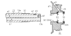
- each of the axial front and rear end faces of the turbine hub 31 at radial positions corresponding to the thrust bearings 34 a and 34 b, as shown in FIGS. 1 to 3, radial directions orthogonal to the axis L of the input shaft 13.
- a plurality of (four each in the present embodiment) oil grooves 46 and 47 extending in the length direction are formed.
- the oil grooves 46 and 47 are equiangularly spaced (90 degrees apart) circumferentially about the axis L of the input shaft 13 of the transmission mechanism, and the second and third hydraulic oil passages of the hydraulic oil passage
- the elements a2 and a3 are formed to be circumferentially offset from each other.
- a second lubricating oil passage b2 communicating with the oil pump on the base end side It is formed to communicate with the radially inner side of each oil groove 47. Then, the lubricating oil supplied via the supply oil passage to the place requiring lubrication (for example, the start clutch 18 etc.) in the housing 16 by the second lubricating oil passage b2 and the respective oil grooves 47 on the rear end face side A return oil passage for returning to the oil pump side is configured.
- the supply oil passage which consists of said 1st lubricating oil passage b1, oil passage formation crevice 45, and each oil groove 46 of the front end face side, said 2nd lubricating oil passage b2, the back end face side
- a return oil passage consisting of the oil grooves 47 of each of the above forms a lubricating oil passage that circulates and supplies ATF as a lubricating oil in the housing 16.
- the first oil passage b1 and the second oil passage b2 constitute an axial oil passage extending in the axial direction, and the oil passage forming recess 45 and the oil grooves 46 and 47 are provided.
- a radial oil passage portion extending at least radially is configured.
- each oil groove 46 on the front end face side among the oil grooves 46 and 47 constituting a part of the radial oil passage portion is a radial oil passage portion in the hydraulic oil passage.
- the installation spaces of the second hydraulic fluid passage a2 and the third hydraulic fluid passage a3 which form a part of the second hydraulic fluid passage a2 overlap the respective installation spaces in the axial direction of the input shaft 13 ing. That is, at the same position in the axial direction of the input shaft 13 or in the vicinity thereof, each oil groove 46, the second hydraulic oil passage a2, and the radially inner portion of the third hydraulic oil passage a3 It is formed along the radial direction in a state of being partially overlapped in the axial direction of the input shaft 13.
- the third hydraulic oil passage a3 constituting a part of the radial oil passage portion in the hydraulic oil passage has a portion on the radially outer side that is a portion on the radially inner side (and a second operation
- the oil seal 50 interposed between the inner peripheral surface of the through hole 32 (large diameter portion 32b) of the turbine hub 31 and the outer peripheral surface 13a of the input shaft 13 of the transmission mechanism will be described in detail.
- the oil seal 50 has an annular fitting member 51 fitted into the large diameter portion 32 b of the through hole 32 in the turbine hub 31, and an outer side in the radial direction on the fitting member 51.
- an annular sealing lip 52 fixed in part.
- the oil seal 50 has an annular spring member 53 as an urging member that urges the radially inner portion on the inner peripheral side of the seal lip 52 against the outer peripheral surface 13 a of the input shaft 13.
- the fitting member 51 is made of a rigid material such as a metal having an L-shaped cross section along the axial direction.
- the fitting member 51 is formed such that its outer diameter is slightly larger than the inner diameter of the large diameter portion 32 b of the through hole 32, and when the fitting member 51 is fitted into the large diameter portion 32 b of the through hole 32.
- the outer surface is in pressure contact with the inner peripheral surface of the large diameter portion 32b.
- a portion on the radially inner portion of the seal lip 52 in sliding contact with the outer peripheral surface of the input shaft 13 is formed to have a curved shape, and the spring member 53 is fitted on the outer peripheral surface of the curved portion. It is united.
- the curved surface of the seal lip 52 is urged radially inward by the spring member 53 and is in sliding contact with the outer peripheral surface 13 a of the input shaft 13 of the transmission mechanism, and this curved surface is in sliding contact with the outer peripheral surface of the input shaft 13
- the radially inner portion of the seal lip 52 is mounted on the outer peripheral surface based on the above.
- an elastic material applied to the seal lip 52 it is desirable to select an appropriate one in consideration of the type of oil to be sealed, the abrasion resistance, the water resistance, and the like.
- the input shaft 13 of the transmission mechanism is inserted into the through hole 32 of the turbine hub 31 by being inserted from the tip end side, but the large diameter portion of the through hole 32 in the turbine hub 31 is Inside 32b, as shown in FIG. 5, a pair of oil seal 50 is attached beforehand. That is, one oil seal 50 is fitted and disposed at each of the deepest portion in the large diameter portion 32b and the opening.
- each oil seal 50 is positioned and mounted at each mounting position (the deepest portion and the opening) in a state in which the movement in the axial direction is restricted. That is, even if the annular concave groove is not formed on the outer peripheral surface 13 a of the input shaft 13, the oil seal 50 has a large diameter of the through hole 32 when the outer surface of the fitting member 51 is elastically deformed. Since the inner peripheral surface of the portion 32 b and the outer peripheral surface 13 a of the input shaft 13 are in pressure contact with each other, the positioning movement is performed with the axial movement restricted.
- the seal lip 52 of the oil seal 50 at the deepest portion tilts while the curved surface of the radially inner portion thereof slides smoothly along the tapered surface 13 b of the tip of the input shaft 13. That is, the end of the input shaft 13 and the radially inner portion of the seal lip 52 will not be caught. Then, when the input shaft 13 is further inserted to the front side in the insertion direction, the seal lip 52 of the oil seal 50 at the deepest portion is pressed against the outer peripheral surface 13 a of the input shaft 13 by the biasing force of the spring member 53. It comes in sliding contact with elastic deformation.
- the seal lip 52 of the oil seal 50 It abuts on the seal lip 52 of the oil seal 50 that has been Then, as in the case of the seal lip 52 of the oil seal 50 at the deepest portion, the curved surface of the radially inner portion of the seal lip 52 of the oil seal 50 at this opening is the tapered surface 13 b of the tip of the input shaft 13 Tilt while sliding smoothly along. Finally, as shown in FIG. 8, the seal lip 52 is further pressed against the outer peripheral surface 13 a of the input shaft 13 by the biasing force of the spring member 53 so as to further increase the pressing force, accompanied by elastic deformation. It comes in sliding contact.
- the splines 30 formed on the outer peripheral surface 13a of the input shaft 13 are unevenly fitted to the splines 33 of the small diameter portion 32a as the input shaft 13 is inserted into the through hole 32, As described above, the insertion direction front side (that is, the inside of the large diameter portion 32b of the through hole 32) is not approached. Therefore, the spline 30 on the input shaft 13 side does not come into contact with the seal lip 52 of the oil seal 50 mounted at the deepest portion of the large diameter portion 32 b of the through hole 32. The lip 52 will not be damaged.
- the input shaft 13 and the turbine hub 31 can not be moved relative to each other in the circumferential direction by the concavo-convex engagement of the two splines 30 and 33, and they are integrally rotatably connected.
- the oil hole 43 of the second hydraulic oil passage a2 opened in the outer peripheral surface 13a on the tip end side of the input shaft 13 is located substantially at the center in the axial direction of the large diameter portion 32b of the through hole 32 in the turbine hub 31.
- a pair of front and rear oil seals 50 inserted between the outer peripheral surface 13 a of the input shaft 13 and the inner peripheral surface of the large diameter portion 32 b of the through hole 32 has oil holes opened on the outer peripheral surface 13 a of the input shaft 13.
- the oil reservoir chamber 31a is formed between the two oil seals 50 in an arrangement mode in which 43 is sandwiched from both sides in the axial direction. Then, the assembling process of connecting the input shaft 13 of the transmission mechanism and the turbine hub 31 so as to be integrally rotatable is completed.
- the first hydraulic oil passage a1 from the oil pump side, and the second ATF is supplied as hydraulic fluid into the hydraulic chamber 37 via the hydraulic fluid passage a2, the oil reservoir chamber 31a, and the third hydraulic fluid passage a3.
- the piston 29 moves in the direction of pressing the outer friction engagement plate 28 against the inner friction engagement plate 27 as the hydraulic pressure in the hydraulic chamber 37 rises, and the start clutch 18 is engaged from the non-engagement state.
- the first lubricating oil passage b1 the oil passage forming recess 45 and The ATF is supplied to the location where the start clutch 18 is disposed via the oil grooves 46 on the front end face side, and the housing 16 is connected via the oil grooves 47 on the rear end face side and the second lubricating oil passage b2.
- ATF is returned from the inside to the oil pump side.
- ATF is supplied as lubricating oil to the start clutch 18 while lubricating the thrust bearing 34a through the oil grooves 46 on the surface side.
- the oil seal 50 is used as a seal member for restricting the leakage of ATF in the axial direction from the oil hole 43 opened in the outer peripheral surface 13a of the input shaft 13.
- the oil seal 50 has the outer surface of the fitting member 51 in pressure contact with the inner peripheral surface of the large diameter portion 32 b of the through hole 32 of the turbine hub 31, and the radial direction of the seal lip 52 with the outer peripheral surface 13 a of the input shaft 13.
- the inner part is mounted immovably in the axial direction by pressure contact with elastic deformation. Therefore, it is unnecessary to provide an annular recessed groove for mounting the seal member in the axial direction so as not to move on the outer peripheral surface 13a of the input shaft 13 of the transmission mechanism.
- an oil hole is formed in the outer peripheral surface 13a of the input shaft 13 of the transmission mechanism while responding to the request for downsizing of the launch device 11 because it is not necessary to secure such a groove arrangement space for the input shaft 13.
- the axial leakage of oil supplied through the oil passage including 43 can be preferably restricted.
- the splines 30 on the input shaft 13 side are formed at positions closer to the base end of the input shaft 13 than the arrangement position of the oil seal 50 on the outer peripheral surface 13 a of the input shaft 13. Therefore, when the input shaft 13 is assembled to the turbine hub 31, the seal lip 52 of the oil seal 50 in which the spline 30 on the input shaft 13 side is fitted into the large diameter portion 32 b of the through hole 32 in the turbine hub 31. There is no contact with Therefore, it is possible to prevent the spline 30 of the input shaft 13 from damaging the seal lip 52 of the oil seal 50 in the process of assembling the input shaft 13.
- the peripheral edge of the tip end surface of the input shaft 13 is chamfered to form a tapered surface 13 b having a smaller diameter toward the tip end. Therefore, when the input shaft 13 is assembled to the turbine hub 31, the curved surface of the radially inner portion of the seal lip 52 of the oil seal 50 slides while smoothly sliding along the tapered surface 13 b of the tip of the input shaft 13 You will come to Therefore, in the process of assembling the input shaft 13, the radially inner portion of the seal lip 52 of the oil seal 50 does not get caught on the tip of the input shaft 13, and the assembly work of the input shaft 13 to the turbine hub 31 is made smooth. You can do it.
- the radially inner portion of the seal lip 52 of the oil seal 50 is bent outward in the radial direction. Therefore, when the input shaft 13 is assembled to the turbine hub 31, the curved surface formed on the radially inner portion of the seal lip 52 smoothly slides from the tip of the input shaft 13 to the outer peripheral surface 13 a. Therefore, in the process of assembling the input shaft 13, the operation of assembling the input shaft 13 to the turbine hub 31 can be smoothly performed without the input shaft 13 being caught on the seal lip 52.
- each oil groove 46 forming a part of the radial oil passage in the lubricating oil passage and a second hydraulic oil passage forming a part of the radial oil passage in the hydraulic oil passage A2 (and the radially inner portion of the third hydraulic fluid passage a3) is formed so as to axially overlap the respective installation spaces. Therefore, in the launch device 11, it is possible to shorten the axial length of the entire device by this overlap.
- each oil groove 46 in the lubricating oil path and the second hydraulic oil path a2 (and the radially inner portion of the third hydraulic oil path a3) in the hydraulic oil path are:
- Each radially outer side portion is extended to be separated from each other in the circumferential direction centering on the axis L of the input shaft 13. Therefore, it is possible to easily realize an oil passage configuration in which the installation spaces of the radial oil passage portions in the respective oil passages partially overlap in the axial direction.
- each oil groove 46 in the lubricating oil passage is disposed radially outward of the portion radially inward of the third hydraulic oil passage a3 in the working oil passage, whereby An oil passage configuration in which the installation space axially overlaps can be easily realized.
- the second hydraulic oil passage a2 constituting the radial oil passage portion is directed radially outward from the first hydraulic oil passage a1 constituting the axial oil passage portion in the hydraulic oil passage.
- the bent position and the hydraulic pressure chamber 37 of the start clutch 18 are disposed apart in the axial direction.
- the third hydraulic fluid passage a3 communicating with the second hydraulic fluid passage a2 via the oil reservoir chamber 31a obliquely penetrates the inside of the turbine hub 31 linearly toward the hydraulic chamber 37. Therefore, the ATF can be promptly supplied to the hydraulic pressure chamber 37.
- the third hydraulic fluid passage a3 which is a part of the radial oil passage portion in the hydraulic fluid passage, is formed in the turbine hub 31 coupled integrally rotatably with the input shaft 13. ing. Therefore, the opening on the inner diameter side of the third hydraulic fluid passage a3 in the turbine hub 31 is always disposed radially opposite to the oil hole 43 formed in the outer peripheral surface portion of the input shaft 13. Therefore, the hydraulic pressure supplied through the first hydraulic oil passage a1 can be responsively supplied to the starting clutch 18 through the third hydraulic oil passage a3.
- a radial oil passage portion of the hydraulic oil passage and a radial oil passage portion of the lubricating oil passage may be formed in the center piece 54 provided substantially at the center of the front cover 14. That is, the third hydraulic fluid passage a3 penetrating the center piece 54 radially outward from the inner peripheral surface of the cylindrical hub portion 54a of the center piece 54 is diagonally connected to communicate with the hydraulic chamber 37. It is formed in a straight line.
- a third lubricating oil passage b3 is formed by the oil groove extending in a vertical direction.
- the third hydraulic fluid passage a3 is formed so that the third lubricating fluid passage b3 is circumferentially offset about the axis L of the input shaft 13.
- the radially inner portion of the seal lip 52 of the oil seal 50 does not necessarily have to be bent radially outward, and may be formed to be linear. In this case, it is desirable that the radially inner portion of the seal lip 52 be inclined with respect to the axial direction.
- the input shaft 13 may not be chamfered on the periphery of the tip end surface thereof.
- the oil seal 50 may be configured such that the spring member 53 for urging the radially inner portion of the seal lip 52 into pressure contact with the outer peripheral surface 13 a of the input shaft 13 is omitted. Also in this case, the radially inner portion of the seal lip 52 can be brought into pressure contact with the outer peripheral surface 13 a of the input shaft 13 with elastic deformation by the elastic force of the seal lip 52 itself.
- oil seal 50 is disposed in the large diameter portion 32b of the through hole 32 of the turbine hub 31, the oil hole 43 opened in the outer peripheral surface 13a of the input shaft 13 is sandwiched from both sides in the axial direction.
- three or more oil seals 50 may be disposed without being limited to a pair of front and rear.
- the second hydraulic fluid passage a2 and the third hydraulic fluid passage a3 that constitute the radial oil passage portion in the hydraulic fluid passage may be formed in a bent or curved shape.
- the thrust bearings 34a and 34b disposed on the front and back sides of the turbine hub 31 may be omitted. In this case, the axial length of the starting device 11 can be shortened by the distance corresponding to the installation space of the thrust bearings 34a and 34b.
- the third hydraulic oil passage a3 constituting a part of the radial oil passage in the hydraulic oil passage is each oil on the front end face side constituting a part of the radial oil passage in the lubricating oil passage.
- the groove 46 and the entire oil passage may overlap in the axial direction.
- the radial oil passage portion is formed bent in the middle of the first lubricating oil passage b1 of the lubricating oil passage, and the oil hole of the radial oil passage portion is the outer peripheral surface of the input shaft 13 in the through hole 32.
- the oil hole may be opened in 13a, and the oil seal may be disposed so as to be disposed in such a manner as to sandwich the oil hole from both sides in the axial direction.
- the second hydraulic fluid passage a2 and the third hydraulic fluid passage a3 that constitute a part of the radial fluid passage in the hydraulic fluid passage are part of the radial fluid passage in the lubricating fluid passage.
- the oil grooves 46 may not be offset in the circumferential direction about the axis L of the input shaft 13. Even in this case, if the radially inward portion of the third hydraulic fluid passage a3 is positioned radially inward of the radially inward portion of each oil groove 46, the axial direction can be obtained.
- An overlapped oil passage structure can be formed.
- the launch device 11 is not limited to the one provided with the multi-plate launch clutch 18.
- the present invention can also be applied to a torque converter or the like provided with a lockup clutch whose engagement state is switched based on hydraulic pressure supplied to the clutch mechanism.
Landscapes
- Engineering & Computer Science (AREA)
- General Engineering & Computer Science (AREA)
- Mechanical Engineering (AREA)
- General Details Of Gearings (AREA)
- Hydraulic Clutches, Magnetic Clutches, Fluid Clutches, And Fluid Joints (AREA)
Priority Applications (2)
| Application Number | Priority Date | Filing Date | Title |
|---|---|---|---|
| DE112008003612.8T DE112008003612B4 (de) | 2008-03-31 | 2008-08-28 | Vorrichtung zum Übertragen eines Drehmoments |
| CN2008801244631A CN101910668B (zh) | 2008-03-31 | 2008-08-28 | 起步装置 |
Applications Claiming Priority (2)
| Application Number | Priority Date | Filing Date | Title |
|---|---|---|---|
| JP2008091407A JP5401821B2 (ja) | 2008-03-31 | 2008-03-31 | 発進装置 |
| JP2008-091407 | 2008-03-31 |
Publications (1)
| Publication Number | Publication Date |
|---|---|
| WO2009122600A1 true WO2009122600A1 (ja) | 2009-10-08 |
Family
ID=41115454
Family Applications (1)
| Application Number | Title | Priority Date | Filing Date |
|---|---|---|---|
| PCT/JP2008/065356 Ceased WO2009122600A1 (ja) | 2008-03-31 | 2008-08-28 | 発進装置 |
Country Status (5)
| Country | Link |
|---|---|
| US (1) | US8215470B2 (enExample) |
| JP (1) | JP5401821B2 (enExample) |
| CN (1) | CN101910668B (enExample) |
| DE (1) | DE112008003612B4 (enExample) |
| WO (1) | WO2009122600A1 (enExample) |
Families Citing this family (29)
| Publication number | Priority date | Publication date | Assignee | Title |
|---|---|---|---|---|
| EP2267329A1 (de) * | 2009-06-24 | 2010-12-29 | ZF Friedrichshafen AG | Kupplungsanordnung, insbesondere für den Antriebsstrang eines Fahrzeugs |
| DE102009045610A1 (de) * | 2009-10-13 | 2011-05-05 | Zf Friedrichshafen Ag | Nasslaufende Kupplungsanordnung |
| JP5513199B2 (ja) * | 2010-03-26 | 2014-06-04 | 本田技研工業株式会社 | エンジンの油圧クラッチ用油路構造 |
| JP5372830B2 (ja) * | 2010-04-13 | 2013-12-18 | 株式会社ユタカ技研 | 動力伝達装置 |
| JP5330310B2 (ja) * | 2010-04-13 | 2013-10-30 | 株式会社ユタカ技研 | 動力伝達装置 |
| JP5605078B2 (ja) * | 2010-08-20 | 2014-10-15 | マツダ株式会社 | トルクコンバータ |
| JP5685112B2 (ja) | 2011-03-07 | 2015-03-18 | Ntn株式会社 | 電気自動車用駆動装置 |
| JP5541259B2 (ja) * | 2011-03-30 | 2014-07-09 | アイシン・エィ・ダブリュ株式会社 | 油圧クラッチおよびそれを備えた変速装置 |
| WO2012132739A1 (ja) * | 2011-03-31 | 2012-10-04 | アイシン・エィ・ダブリュ株式会社 | 発進装置 |
| JP5621916B2 (ja) * | 2011-03-31 | 2014-11-12 | アイシン・エィ・ダブリュ株式会社 | 発進装置 |
| JP5609897B2 (ja) * | 2012-01-16 | 2014-10-22 | マツダ株式会社 | トルクコンバータ |
| DE102012201510A1 (de) * | 2012-02-02 | 2013-08-08 | Zf Friedrichshafen Ag | Kupplungsanordnung |
| JP2014066317A (ja) * | 2012-09-26 | 2014-04-17 | Aisin Seiki Co Ltd | トルクコンバータ |
| JP6155782B2 (ja) * | 2013-04-11 | 2017-07-05 | スズキ株式会社 | 自動二輪車用クラッチ装置の潤滑構造 |
| DE112014003759B4 (de) | 2013-09-26 | 2018-11-15 | Aisin Aw Co., Ltd. | Kupplung mit einseitigen Reibscheiben |
| DE102013018713B4 (de) * | 2013-11-08 | 2025-10-02 | Sew-Eurodrive Gmbh & Co Kg | Getriebe mit Gehäuse |
| KR101519269B1 (ko) * | 2013-12-18 | 2015-05-11 | 현대자동차주식회사 | 발진 클러치장치 |
| CN105443605B (zh) * | 2015-12-18 | 2017-11-03 | 陕西航天动力高科技股份有限公司 | 独立式湿式主离合器总成 |
| US9759302B2 (en) * | 2016-01-25 | 2017-09-12 | Ford Global Technologies, Llc | Bypass clutch for a torque converter |
| JP6656967B2 (ja) * | 2016-03-18 | 2020-03-04 | 株式会社エクセディ | トルクコンバータのロックアップ装置 |
| JP6725278B2 (ja) * | 2016-03-18 | 2020-07-15 | 株式会社エクセディ | トルクコンバータのロックアップ装置 |
| JP6967994B2 (ja) * | 2018-02-23 | 2021-11-17 | 本田技研工業株式会社 | 潤滑油供給装置 |
| JP2020122549A (ja) * | 2019-01-31 | 2020-08-13 | 株式会社小松製作所 | 作業機械 |
| DE102019201646A1 (de) * | 2019-02-08 | 2020-08-13 | Zf Friedrichshafen Ag | Kupplungsanordnung |
| DE102019201644A1 (de) | 2019-02-08 | 2020-08-13 | Zf Friedrichshafen Ag | Kupplungsanordnung |
| JP6734967B1 (ja) * | 2019-06-07 | 2020-08-05 | 川崎重工業株式会社 | 湿式多板クラッチの給油構造およびアジマススラスタ |
| US11802596B2 (en) * | 2020-11-25 | 2023-10-31 | Dana Belgium N.V. | Systems and methods for rotary seal drag reduction |
| CN113483088B (zh) * | 2021-07-22 | 2022-06-14 | 中国船舶重工集团公司第七0三研究所 | 一种带有供油装置的船用齿轮箱摩擦离合器输入轴组件 |
| KR102876353B1 (ko) * | 2022-11-28 | 2025-10-29 | 주식회사 카펙발레오 | 하이브리드 구동 모듈 |
Citations (3)
| Publication number | Priority date | Publication date | Assignee | Title |
|---|---|---|---|---|
| JPH0765645B2 (ja) * | 1987-03-31 | 1995-07-19 | 日産自動車株式会社 | 自動変速機の油路構造 |
| JP2000283188A (ja) * | 1999-03-26 | 2000-10-13 | Aisin Aw Co Ltd | 流体継手装置 |
| JP2000320572A (ja) * | 1999-03-10 | 2000-11-24 | Nsk Warner Kk | 発進クラッチ |
Family Cites Families (12)
| Publication number | Priority date | Publication date | Assignee | Title |
|---|---|---|---|---|
| FR336843A (fr) * | 1903-10-31 | 1904-03-18 | Auerbach Et Cie Soc | Outil à percer des trous à angles vifs |
| JPH0755401Y2 (ja) * | 1987-07-23 | 1995-12-20 | 日産自動車株式会社 | 変速機の油路構造 |
| JP2765645B2 (ja) | 1992-06-19 | 1998-06-18 | 株式会社小糸製作所 | 自動車用ヘッドランプにおけるエイミング用水準器 |
| DE4342439C2 (de) * | 1992-12-17 | 1995-11-30 | Daimler Benz Ag | Hydrodynamischer Drehmomentwandler mit einer Überbrückungskupplung |
| KR0111136Y1 (en) | 1993-08-09 | 1997-12-22 | Um Jung Tae | Auto moving forward tapeline |
| JP3715114B2 (ja) * | 1998-09-09 | 2005-11-09 | 株式会社エクセディ | トルクコンバータ |
| US6332521B1 (en) * | 1999-03-10 | 2001-12-25 | Nsk-Warner K.K. | Starting clutch |
| DE19932576B4 (de) * | 1999-07-13 | 2011-03-03 | Zf Sachs Ag | Hydrodynamischer Drehmomentwandler |
| JP4267445B2 (ja) | 2001-08-14 | 2009-05-27 | アイシン・エィ・ダブリュ株式会社 | 発進クラッチ装置 |
| EP1584830B2 (de) * | 2004-04-10 | 2016-09-21 | BorgWarner, Inc. | Kupplungseinrichtung, insbesondere Anfahrkupplungseinrichtung |
| DE102004060256A1 (de) * | 2004-12-15 | 2006-06-29 | Zf Friedrichshafen Ag | Hydrodynamische Kopplungsvorrichtung |
| DE102006009987A1 (de) * | 2006-03-03 | 2007-09-06 | Zf Friedrichshafen Ag | Hydrodynamische Kopplungsvorrichtung |
-
2008
- 2008-03-31 JP JP2008091407A patent/JP5401821B2/ja active Active
- 2008-08-28 CN CN2008801244631A patent/CN101910668B/zh active Active
- 2008-08-28 DE DE112008003612.8T patent/DE112008003612B4/de active Active
- 2008-08-28 WO PCT/JP2008/065356 patent/WO2009122600A1/ja not_active Ceased
-
2009
- 2009-01-23 US US12/320,335 patent/US8215470B2/en active Active
Patent Citations (3)
| Publication number | Priority date | Publication date | Assignee | Title |
|---|---|---|---|---|
| JPH0765645B2 (ja) * | 1987-03-31 | 1995-07-19 | 日産自動車株式会社 | 自動変速機の油路構造 |
| JP2000320572A (ja) * | 1999-03-10 | 2000-11-24 | Nsk Warner Kk | 発進クラッチ |
| JP2000283188A (ja) * | 1999-03-26 | 2000-10-13 | Aisin Aw Co Ltd | 流体継手装置 |
Also Published As
| Publication number | Publication date |
|---|---|
| CN101910668B (zh) | 2013-08-07 |
| JP5401821B2 (ja) | 2014-01-29 |
| US8215470B2 (en) | 2012-07-10 |
| JP2009243597A (ja) | 2009-10-22 |
| DE112008003612B4 (de) | 2015-05-28 |
| CN101910668A (zh) | 2010-12-08 |
| US20090242348A1 (en) | 2009-10-01 |
| DE112008003612T5 (de) | 2010-10-28 |
Similar Documents
| Publication | Publication Date | Title |
|---|---|---|
| JP5401821B2 (ja) | 発進装置 | |
| KR100881792B1 (ko) | 발진 클러치 장치 | |
| JP5835391B2 (ja) | 発進装置 | |
| JP5472486B2 (ja) | 車両用動力伝達装置 | |
| CN102224354B (zh) | 干式离合器 | |
| US10302150B2 (en) | Clutch | |
| KR20170107924A (ko) | 습식 이중 클러치용 유압식 제어 시스템 | |
| US10458484B2 (en) | Dual clutch | |
| KR20170107926A (ko) | 제어 시스템 상에 지지된 습식 이중 클러치 | |
| JP2009133444A (ja) | トルクコンバータ | |
| JP4720302B2 (ja) | 自動変速機のクラッチ装置 | |
| KR20170107927A (ko) | 제어 시스템의 피스톤의 행정을 제한할 수 있는 안전 베어링을 구비한 습식 이중 클러치 | |
| KR20160042387A (ko) | 습식 이중 클러치 메커니즘을 포함하는 트랜스미션 시스템 | |
| KR101786805B1 (ko) | 이중 클러치용 액츄에이터 | |
| JP6173814B2 (ja) | クラッチ | |
| JP5250822B2 (ja) | トルク伝達装置 | |
| JP4978536B2 (ja) | 発進装置 | |
| JP2022158058A (ja) | 流体継手 | |
| JP6034641B2 (ja) | 発進装置 | |
| JP5986868B2 (ja) | クラッチ | |
| KR20150003976A (ko) | 브레이크 | |
| KR20180058901A (ko) | 이중 클러치 | |
| JP7326046B2 (ja) | 流体継手及びトルクコンバータ | |
| JP2007333075A (ja) | 流体伝動装置と出力部材との接続構造 | |
| JP2004360849A (ja) | トルクコンバータ |
Legal Events
| Date | Code | Title | Description |
|---|---|---|---|
| WWE | Wipo information: entry into national phase |
Ref document number: 200880124463.1 Country of ref document: CN |
|
| 121 | Ep: the epo has been informed by wipo that ep was designated in this application |
Ref document number: 08873773 Country of ref document: EP Kind code of ref document: A1 |
|
| RET | De translation (de og part 6b) |
Ref document number: 112008003612 Country of ref document: DE Date of ref document: 20101028 Kind code of ref document: P |
|
| 122 | Ep: pct application non-entry in european phase |
Ref document number: 08873773 Country of ref document: EP Kind code of ref document: A1 |