WO2009113252A1 - 車輪用軸受装置 - Google Patents
車輪用軸受装置 Download PDFInfo
- Publication number
- WO2009113252A1 WO2009113252A1 PCT/JP2009/000792 JP2009000792W WO2009113252A1 WO 2009113252 A1 WO2009113252 A1 WO 2009113252A1 JP 2009000792 W JP2009000792 W JP 2009000792W WO 2009113252 A1 WO2009113252 A1 WO 2009113252A1
- Authority
- WO
- WIPO (PCT)
- Prior art keywords
- cap
- wheel
- bearing device
- wheel bearing
- axial direction
- Prior art date
Links
Images


Classifications
-
- B—PERFORMING OPERATIONS; TRANSPORTING
- B60—VEHICLES IN GENERAL
- B60B—VEHICLE WHEELS; CASTORS; AXLES FOR WHEELS OR CASTORS; INCREASING WHEEL ADHESION
- B60B27/00—Hubs
- B60B27/0015—Hubs for driven wheels
- B60B27/0021—Hubs for driven wheels characterised by torque transmission means from drive axle
- B60B27/0026—Hubs for driven wheels characterised by torque transmission means from drive axle of the radial type, e.g. splined key
-
- B—PERFORMING OPERATIONS; TRANSPORTING
- B60—VEHICLES IN GENERAL
- B60B—VEHICLE WHEELS; CASTORS; AXLES FOR WHEELS OR CASTORS; INCREASING WHEEL ADHESION
- B60B27/00—Hubs
- B60B27/0005—Hubs with ball bearings
-
- B—PERFORMING OPERATIONS; TRANSPORTING
- B60—VEHICLES IN GENERAL
- B60B—VEHICLE WHEELS; CASTORS; AXLES FOR WHEELS OR CASTORS; INCREASING WHEEL ADHESION
- B60B27/00—Hubs
- B60B27/0078—Hubs characterised by the fixation of bearings
- B60B27/0084—Hubs characterised by the fixation of bearings caulking to fix inner race
-
- B—PERFORMING OPERATIONS; TRANSPORTING
- B60—VEHICLES IN GENERAL
- B60B—VEHICLE WHEELS; CASTORS; AXLES FOR WHEELS OR CASTORS; INCREASING WHEEL ADHESION
- B60B7/00—Wheel cover discs, rings, or the like, for ornamenting, protecting, venting, or obscuring, wholly or in part, the wheel body, rim, hub, or tyre sidewall, e.g. wheel cover discs, wheel cover discs with cooling fins
- B60B7/06—Fastening arrangements therefor
- B60B7/061—Fastening arrangements therefor characterised by the part of the wheels to which the discs, rings or the like are mounted
- B60B7/066—Fastening arrangements therefor characterised by the part of the wheels to which the discs, rings or the like are mounted to the hub
-
- F—MECHANICAL ENGINEERING; LIGHTING; HEATING; WEAPONS; BLASTING
- F16—ENGINEERING ELEMENTS AND UNITS; GENERAL MEASURES FOR PRODUCING AND MAINTAINING EFFECTIVE FUNCTIONING OF MACHINES OR INSTALLATIONS; THERMAL INSULATION IN GENERAL
- F16C—SHAFTS; FLEXIBLE SHAFTS; ELEMENTS OR CRANKSHAFT MECHANISMS; ROTARY BODIES OTHER THAN GEARING ELEMENTS; BEARINGS
- F16C35/00—Rigid support of bearing units; Housings, e.g. caps, covers
- F16C35/04—Rigid support of bearing units; Housings, e.g. caps, covers in the case of ball or roller bearings
- F16C35/06—Mounting or dismounting of ball or roller bearings; Fixing them onto shaft or in housing
- F16C35/063—Fixing them on the shaft
-
- F—MECHANICAL ENGINEERING; LIGHTING; HEATING; WEAPONS; BLASTING
- F16—ENGINEERING ELEMENTS AND UNITS; GENERAL MEASURES FOR PRODUCING AND MAINTAINING EFFECTIVE FUNCTIONING OF MACHINES OR INSTALLATIONS; THERMAL INSULATION IN GENERAL
- F16C—SHAFTS; FLEXIBLE SHAFTS; ELEMENTS OR CRANKSHAFT MECHANISMS; ROTARY BODIES OTHER THAN GEARING ELEMENTS; BEARINGS
- F16C35/00—Rigid support of bearing units; Housings, e.g. caps, covers
- F16C35/04—Rigid support of bearing units; Housings, e.g. caps, covers in the case of ball or roller bearings
- F16C35/06—Mounting or dismounting of ball or roller bearings; Fixing them onto shaft or in housing
- F16C35/07—Fixing them on the shaft or housing with interposition of an element
- F16C35/073—Fixing them on the shaft or housing with interposition of an element between shaft and inner race ring
-
- F—MECHANICAL ENGINEERING; LIGHTING; HEATING; WEAPONS; BLASTING
- F16—ENGINEERING ELEMENTS AND UNITS; GENERAL MEASURES FOR PRODUCING AND MAINTAINING EFFECTIVE FUNCTIONING OF MACHINES OR INSTALLATIONS; THERMAL INSULATION IN GENERAL
- F16C—SHAFTS; FLEXIBLE SHAFTS; ELEMENTS OR CRANKSHAFT MECHANISMS; ROTARY BODIES OTHER THAN GEARING ELEMENTS; BEARINGS
- F16C19/00—Bearings with rolling contact, for exclusively rotary movement
- F16C19/02—Bearings with rolling contact, for exclusively rotary movement with bearing balls essentially of the same size in one or more circular rows
- F16C19/14—Bearings with rolling contact, for exclusively rotary movement with bearing balls essentially of the same size in one or more circular rows for both radial and axial load
- F16C19/18—Bearings with rolling contact, for exclusively rotary movement with bearing balls essentially of the same size in one or more circular rows for both radial and axial load with two or more rows of balls
- F16C19/181—Bearings with rolling contact, for exclusively rotary movement with bearing balls essentially of the same size in one or more circular rows for both radial and axial load with two or more rows of balls with angular contact
- F16C19/183—Bearings with rolling contact, for exclusively rotary movement with bearing balls essentially of the same size in one or more circular rows for both radial and axial load with two or more rows of balls with angular contact with two rows at opposite angles
- F16C19/184—Bearings with rolling contact, for exclusively rotary movement with bearing balls essentially of the same size in one or more circular rows for both radial and axial load with two or more rows of balls with angular contact with two rows at opposite angles in O-arrangement
- F16C19/186—Bearings with rolling contact, for exclusively rotary movement with bearing balls essentially of the same size in one or more circular rows for both radial and axial load with two or more rows of balls with angular contact with two rows at opposite angles in O-arrangement with three raceways provided integrally on parts other than race rings, e.g. third generation hubs
-
- F—MECHANICAL ENGINEERING; LIGHTING; HEATING; WEAPONS; BLASTING
- F16—ENGINEERING ELEMENTS AND UNITS; GENERAL MEASURES FOR PRODUCING AND MAINTAINING EFFECTIVE FUNCTIONING OF MACHINES OR INSTALLATIONS; THERMAL INSULATION IN GENERAL
- F16C—SHAFTS; FLEXIBLE SHAFTS; ELEMENTS OR CRANKSHAFT MECHANISMS; ROTARY BODIES OTHER THAN GEARING ELEMENTS; BEARINGS
- F16C19/00—Bearings with rolling contact, for exclusively rotary movement
- F16C19/52—Bearings with rolling contact, for exclusively rotary movement with devices affected by abnormal or undesired conditions
- F16C19/527—Bearings with rolling contact, for exclusively rotary movement with devices affected by abnormal or undesired conditions related to vibration and noise
-
- F—MECHANICAL ENGINEERING; LIGHTING; HEATING; WEAPONS; BLASTING
- F16—ENGINEERING ELEMENTS AND UNITS; GENERAL MEASURES FOR PRODUCING AND MAINTAINING EFFECTIVE FUNCTIONING OF MACHINES OR INSTALLATIONS; THERMAL INSULATION IN GENERAL
- F16C—SHAFTS; FLEXIBLE SHAFTS; ELEMENTS OR CRANKSHAFT MECHANISMS; ROTARY BODIES OTHER THAN GEARING ELEMENTS; BEARINGS
- F16C2326/00—Articles relating to transporting
- F16C2326/01—Parts of vehicles in general
- F16C2326/02—Wheel hubs or castors
-
- F—MECHANICAL ENGINEERING; LIGHTING; HEATING; WEAPONS; BLASTING
- F16—ENGINEERING ELEMENTS AND UNITS; GENERAL MEASURES FOR PRODUCING AND MAINTAINING EFFECTIVE FUNCTIONING OF MACHINES OR INSTALLATIONS; THERMAL INSULATION IN GENERAL
- F16D—COUPLINGS FOR TRANSMITTING ROTATION; CLUTCHES; BRAKES
- F16D3/00—Yielding couplings, i.e. with means permitting movement between the connected parts during the drive
- F16D3/16—Universal joints in which flexibility is produced by means of pivots or sliding or rolling connecting parts
- F16D3/20—Universal joints in which flexibility is produced by means of pivots or sliding or rolling connecting parts one coupling part entering a sleeve of the other coupling part and connected thereto by sliding or rolling members
- F16D3/22—Universal joints in which flexibility is produced by means of pivots or sliding or rolling connecting parts one coupling part entering a sleeve of the other coupling part and connected thereto by sliding or rolling members the rolling members being balls, rollers, or the like, guided in grooves or sockets in both coupling parts
- F16D3/223—Universal joints in which flexibility is produced by means of pivots or sliding or rolling connecting parts one coupling part entering a sleeve of the other coupling part and connected thereto by sliding or rolling members the rolling members being balls, rollers, or the like, guided in grooves or sockets in both coupling parts the rolling members being guided in grooves in both coupling parts
- F16D2003/22326—Attachments to the outer joint member, i.e. attachments to the exterior of the outer joint member or to the shaft of the outer joint member
Definitions
- the present invention relates to a wheel bearing device for supporting a wheel of a vehicle such as an automobile, and more specifically, a drive wheel (a front wheel of an FF vehicle, FR) provided with a wheel bearing and a constant velocity universal joint and mounted on an independent suspension type suspension.
- the present invention relates to a wheel bearing device that rotatably supports a rear wheel of a car or an RR car and all wheels of a 4WD car) with respect to a suspension device.
- a power transmission device that transmits engine power of a vehicle such as an automobile to a wheel transmits power from the engine to the wheel, and also causes radial or axial displacement from the wheel that occurs when the vehicle bounces or turns when traveling on a rough road.
- one end of the drive shaft interposed between the engine side and the drive wheel side is connected to the differential through a sliding type constant velocity universal joint, and the like.
- the end is connected to the drive wheel via a wheel bearing device including a fixed type constant velocity universal joint.
- the wheel bearing device 50 is connected to a hub wheel 51 for mounting a wheel (not shown) at one end, a double row rolling bearing 52 for rotatably supporting the hub wheel 51, and the hub wheel 51.
- a fixed type constant velocity universal joint 53 that transmits power of a drive shaft (not shown) to the hub wheel 51 is provided.
- the hub wheel 51 integrally has a wheel mounting flange 54 for mounting a wheel at one end, an inner rolling surface 51a on the outer periphery, and a cylindrical small-diameter step portion 51b extending in the axial direction from the inner rolling surface 51a. Is formed.
- the double-row rolling bearing 52 has a vehicle body mounting flange 55b integrally fixed to a suspension device (not shown) on the outer periphery, and an outer side in which double-row outer rolling surfaces 55a and 55a are formed on the inner periphery. It comprises a member 55 and an inner member 57 inserted into the outer member 55 via double rows of balls 56.
- the inner member 57 includes a hub wheel 51 and a separate inner ring 58 that is press-fitted into the small-diameter step portion 51b of the hub wheel 51 and has an inner rolling surface 58a formed on the outer periphery.
- the inner ring 58 is fixed to the hub wheel 51 in the axial direction by a caulking portion 51 c formed by plastically deforming the end portion of the small-diameter stepped portion 51 b of the hub wheel 51 radially outward.
- the constant velocity universal joint 53 includes an outer joint member 62 integrally including a cup-shaped mouth portion 59, a shoulder portion 60 that forms the bottom of the mouth portion 59, and a shaft portion 61 that extends from the shoulder portion 60 in the axial direction.
- the outer joint member 62 is fitted into the hub wheel 51 so as to be able to transmit torque. That is, the female serration 63 is formed on the inner periphery of the hub wheel 51, and the male serration 64 is formed on the outer periphery of the shaft portion 61 of the outer joint member 62, and both the serrations 63 and 64 are engaged with each other.
- the shaft portion 61 of the outer joint member 62 is fitted into the hub wheel 51 until the shoulder portion 60 is abutted against the caulking portion 51 c of the hub wheel 51, and the male screw 65 formed at the end of the shaft portion 61.
- the fixing nut 66 is fastened with a predetermined tightening torque, and the hub wheel 51 and the outer joint member 62 are detachably coupled in the axial direction.
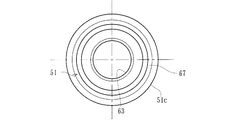
- a portion that contacts the shoulder portion 60 of the outer joint member 62, that is, a caulking portion 51c of the hub wheel 51 is formed on a flat surface, as shown in FIG.
- the concave groove 67 is formed in the central portion in the radial direction of the flat surface of the caulking portion 51c.
- grease is filled in the concave groove 67.
- the present invention has been made in view of the above circumstances, and is a wheel bearing that alleviates a sudden slip that occurs between a caulking portion and a shoulder portion of an outer joint member, and prevents the occurrence of stick-slip noise.
- the object is to provide a device.
- the invention according to claim 1 of the present invention includes an outer member in which a double row outer rolling surface is integrally formed on the inner periphery, and a wheel for attaching a wheel to one end.
- a hub ring integrally having a mounting flange and having a cylindrical small-diameter step portion extending in the axial direction on the outer periphery, and at least one inner ring press-fitted into the small-diameter step portion of the hub ring,
- a movable body and a constant velocity universal joint connected to the hub ring, and the inner ring is connected to the hub ring by a caulking portion formed by plastically deforming an end of the small diameter step portion radially outward.
- the outer joint member of the constant velocity universal joint is fixed in the axial direction, and a cup-shaped mouth portion and this A shoulder portion that forms the bottom of the usb portion, and a stem portion that extends in the axial direction from the shoulder portion and is internally fitted to the hub wheel so as to be able to transmit torque via serrations, are integrally formed with the shoulder portion.
- a cap made of a low friction member is interposed between the crimping portion and the shoulder portion.
- the cap includes a disk-shaped contact portion, a cylindrical portion extending in an axial direction from an outer diameter portion of the contact portion, and a locking portion protruding radially inward from an end portion of the cylindrical portion.
- an inner diameter of the locking portion is set to be slightly smaller than an outer diameter of the crimping portion, and the cap is attached to the crimping portion by elastically deforming the locking portion.
- the caulking part and the shoulder A cap made of a low-friction member is interposed between the cylindrical portion, and the cap includes a disk-shaped contact portion, a cylindrical portion extending in an axial direction from the outer diameter portion of the contact portion, and the cylindrical portion A locking portion protruding radially inward from the end portion, the inner diameter of the locking portion is set to be slightly smaller than the outer diameter of the caulking portion, and the locking portion is elastically deformed.
- the cap Since the cap is attached to the caulking portion, when a large torque is applied to the drive shaft and a large twist occurs in the outer joint member, the cap is either one of the caulking portion and the shoulder portion of the outer joint member. To be accompanied by a moment later This reduces the friction coefficient of the abutment surface and suppresses the wear of the cap itself and the caulking part, and also reduces the sudden slip that occurs between the caulking part and the shoulder part with this cap. Generation of slip noise can be prevented.
- the cap is formed by pressing from a steel plate and a low friction film is formed on the surface by the permeation diffusion plating of molybdenum disulfide, as in the invention described in claim 2, the adhesion is improved. It is effective for this kind of application, which has good durability and abrupt slip on the contact surface.
- the ground treatment is performed by spraying grid-like silicon carbide on the surface of the cap, the adhesion of the low friction film can be improved.
- the cap may be formed by injection molding from a synthetic resin material to which a fibrous reinforcing material is added.
- the slit extended in an axial direction may be formed in the outer-diameter part which extends over the latching
- the locking portion may be formed of a locking piece formed in the circumferential direction. Thereby, it can be easily elastically deformed without strictly restricting the dimension of the locking portion, and the assembling performance of the cap is improved.
- the wheel bearing device integrally has an outer member integrally formed with a double row outer rolling surface on the inner periphery, and a wheel mounting flange for mounting the wheel on one end, and on the outer periphery.
- a hub wheel formed with a cylindrical small-diameter step portion extending in the axial direction, and at least one inner ring press-fitted into the small-diameter step portion of the hub wheel.
- a constant velocity universal joint and the inner ring is axially fixed to the hub ring by a caulking portion formed by plastically deforming an end of the small diameter step portion radially outward.
- the outer joint member of the universal joint includes a cup-shaped mouth portion and a shoulder portion that forms the bottom of the mouth portion,
- the hub wheel is integrally provided with a stem portion that extends in an axial direction from the shoulder portion and is fitted into the hub wheel so as to transmit torque via serration, and the shoulder portion is in contact with the caulking portion.
- a cap made of a low friction member is interposed between the caulking portion and the shoulder portion.
- a contact portion a cylindrical portion extending in an axial direction from an outer diameter portion of the contact portion; and a locking portion protruding radially inward from an end portion of the cylindrical portion.
- An outer member integrally having a vehicle body mounting flange on the outer periphery, an outer member formed integrally with a double row outer rolling surface on the inner periphery, a wheel mounting flange integrally on one end, and the double row on the outer periphery.
- a hub ring formed with an inner rolling surface facing one of the outer rolling surfaces, a cylindrical small diameter step portion extending in an axial direction from the inner rolling surface, and a small diameter step portion of the hub ring,
- An inner member composed of an inner ring having an inner race surface formed with an inner race surface facing the other of the outer rows of the double rows on the outer periphery, and freely rollable between both raceway surfaces of the inner member and the outer member.
- a constant velocity universal joint connected to the hub wheel, and a crimping portion formed by plastically deforming an end portion of the small diameter step portion radially outward.
- An inner ring is fixed in an axial direction with respect to the hub ring, and an outer joint member of the constant velocity universal joint is a cup-shaped mouse. And a stem part extending in the axial direction from the shoulder part and fitted in the hub wheel so as to be able to transmit torque via serration.
- a cap formed by pressing from the steel plate is attached to the caulking portion
- the cap protrudes inward in the radial direction from the disk-shaped contact portion, the cylindrical portion extending in the axial direction from the outer diameter portion of the contact portion, and the end portion of the cylindrical portion.
- a locking portion having a diameter slightly smaller than the outer diameter of the tightening portion, and a low-friction film formed by permeation diffusion plating of molybdenum disulfide is formed on the surface of the cap.
- FIG. 1 is a longitudinal sectional view showing an embodiment of a wheel bearing device according to the present invention
- FIG. 2 is an enlarged view of a main part of FIG. 1
- FIG. 3 is a test of a sample equipped with a cap according to the present invention.
- FIG. 4 is a graph showing a waveform in a test of a sample as a comparative example
- FIG. 5A is a front view showing a modified example of the cap of FIG. 2, and FIG. FIG.
- the side closer to the outer side of the vehicle when assembled to the vehicle is referred to as the outer side (left side in FIG. 1), and the side closer to the center is referred to as the inner side (right side in FIG. 1).
- This wheel bearing device is referred to as a third generation for driving wheels, and is a double row rolling element (ball) accommodated in a freely rollable manner between the inner member 1, the outer member 10, and both members 1, 10.
- the constant velocity universal joint 13 is detachably coupled.
- the inner member 1 includes a hub ring 2 and an inner ring 3 press-fitted into the hub ring 2.
- the hub wheel 2 integrally has a wheel mounting flange 4 for attaching a wheel (not shown) to an end portion on the outer side, one (outer side) inner rolling surface 2a on the outer periphery, and this inner rolling.
- a cylindrical small diameter step portion 2b extending in the axial direction from the surface 2a is formed, and a serration (or spline) 2c for torque transmission is formed on the inner periphery.
- Hub bolts 5 for attaching the wheels are planted at circumferentially equidistant positions of the wheel mounting flanges 4.
- the hub wheel 2 is formed of medium and high carbon steel containing 0.40 to 0.80% by weight of carbon such as S53C, and includes a base portion serving as a seal land portion in which an outer rolling seal 11 to be described later comes into sliding contact with the inner rolling surface 2a. 7 to the small diameter step portion 2b, the surface hardness is set in the range of 58 to 64HRC by induction hardening. Then, the inner ring 3 with the other (inner side) inner rolling surface 3a formed on the outer periphery is press-fitted into the small-diameter step portion 2b of the hub wheel 2 via a predetermined shimiro, and the end portion of the small-diameter step portion 2b is radially inserted.
- the inner ring 3 is fixed in the axial direction by a caulking portion 6 formed by plastic deformation outward.
- the end surface of the crimping portion 6 is formed as a flat surface, so that the surface pressure applied to the crimping portion 6 by the axial force can be reduced, and plastic deformation and wear of the crimping portion 6 can be prevented.
- the inner ring 3 and the rolling element 8 are made of high carbon chrome steel such as SUJ2, and the other (inner side) inner rolling surface 3a is formed on the outer periphery, and is hardened in the range of 58 to 64 HRC to the core part by quenching. Has been processed.
- the outer member 10 integrally has a vehicle body mounting flange 10b for mounting to the vehicle body (not shown) on the outer periphery, and has a double row facing the inner rolling surfaces 2a and 3a of the inner member 1 on the inner periphery.
- Outer rolling surfaces 10a and 10a are integrally formed.
- the outer member 10 is made of medium and high carbon steel containing 0.40 to 0.80% by weight of carbon such as S53C, and the double row outer rolling surfaces 10a and 10a have a surface hardness in the range of 58 to 64HRC by induction hardening. Is cured.
- the double-row rolling elements 8 and 8 are accommodated so that rolling is possible via the holder
- Seals 11 and 12 are attached to the opening of the annular space formed between the outer member 10 and the inner member 1 to prevent leakage of the lubricating grease sealed inside the bearing and from the outside. It prevents rainwater and dust from entering the
- a double row angular contact ball bearing using a ball as the rolling element 8 is exemplified.
- the present invention is not limited to this.
- a double row tapered roller bearing using a tapered roller as the rolling element 8 is provided.
- a so-called third generation structure in which one inner rolling surface 2a is directly formed on the outer periphery of the hub wheel 2 is illustrated, but although not illustrated, a pair of inner rings are provided on the small-diameter step portion of the hub wheel. It may be a so-called first or second generation structure that is press-fitted.
- the constant velocity universal joint 13 includes an outer joint member 14, a joint inner ring, a cage and a torque transmission ball (not shown).
- the outer joint member 14 is made of medium-high carbon steel containing 0.40 to 0.80% by weight of carbon such as S53C, and has a cup-shaped mouth portion (not shown) and a shoulder portion 15 that forms the bottom of the mouth portion.
- the stem portion 16 extending in the axial direction from the shoulder portion 15 is integrally provided.
- the stem portion 16 has a serration (or spline) 16a engaged with the serration 2c of the hub wheel 2 on the outer periphery, and a male screw 16b formed at the end of the serration 16a.
- the stem portion 16 of the outer joint member 14 is fitted and inserted into the hub wheel 2 until the shoulder portion 15 abuts against the caulking portion 6 via a cap 17 which will be described later, and the caulking portion 6 and the shoulder portion 15 face each other.
- the fixing nut 18 is fastened to the male screw 16b with a predetermined tightening torque, and the hub wheel 2 and the outer joint member 14 are detachably coupled in the axial direction.
- a cap 17 is attached to the caulking portion 6.
- the cap 17 has a cross-section by pressing a corrosion-resistant steel plate such as a cold-rolled steel plate (JIS standard SPCC type) or austenitic stainless steel plate (JIS standard SUS304 type) that has been rust-proofed.
- a corrosion-resistant steel plate such as a cold-rolled steel plate (JIS standard SPCC type) or austenitic stainless steel plate (JIS standard SUS304 type) that has been rust-proofed.
- JIS standard SPCC type cold-rolled steel plate
- austenitic stainless steel plate JIS standard SUS304 type
- the inner diameter of the locking portion 17c is set to be slightly smaller than the outer diameter of the crimping portion 6, and the cap 17 is attached to the crimping portion 6 by elastically deforming the locking portion 17c.
- the cap 17 faces the large end surface 3b of the inner ring 3 through an axial clearance of 1 mm at the maximum, and has a labyrinth structure.
- the cap 17 can be attached to the caulking portion 6 with one touch, and the cap 17 can be prevented from falling off from the caulking portion 6 in the assembling process, and the labyrinth structure allows the cap 17 to move to the caulking portion 6. Intrusion of foreign matter such as rainwater and dust can be prevented, and rusting of the crimped portion 6 can be prevented to improve durability.
- the elastic deformation can be performed without strictly restricting the size of the locking portion 17c.
- the cap 17 can be easily assembled.
- a low friction film 19 having a film thickness of 0.3 to 1.0 mm is formed on the surface of the cap 17.
- the low friction film 19 is formed by a so-called PIP process (penetration diffusion plating process) in which a powder made of molybdenum disulfide is shot peened on the surface of the cap 17 to diffuse and infiltrate the element.
- this treatment was performed by applying molybdenum disulfide having a particle size of about 5 ⁇ m in a scaly particle shape at an injection pressure of 0.5 MPa for about 20 sec. This is done by shot peening.
- ground treatment by spraying grid-like SiC (silicon carbide) having a particle size number of 400 (40 to 50 ⁇ m) onto the surface of the cap 17.
- the cap 17 on which such a low friction film 19 is formed is attached to the caulking portion 6, and the caulking portion 6 and the shoulder portion 15 are in contact with each other through the cap 17, and the hub wheel 2 and the outer joint member 14 are in the axial direction. Since a large torque is applied to the drive shaft (not shown) and a large twist occurs in the outer joint member 14, the cap 17 is attached to the shoulders of the caulking portion 6 and the outer joint member 14. The unit 15 will be accompanied by a momentary delay. Accordingly, the friction coefficient of the abutting surface is reduced to suppress the wear of the cap 17 itself and the wear of the caulking portion 6, and a sudden slip generated between the caulking portion 6 and the shoulder portion 15 is caused by the cap 17. And can prevent the occurrence of stick-slip noise.
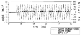
- FIG. 3 and 4 show the results of the abnormal noise generation test conducted by the applicant.
- FIG. 3 shows a waveform graph of a sample with a low friction coating 19 according to the present invention, that is, a sample with a cap 17 whose surface is subjected to PIP treatment of molybdenum disulfide
- FIG. 4 is a sample with other caps attached.
- the waveform graph of (typical example) is shown.
- the test conditions are a set axial force of 50 kN, an input torque of ⁇ 0.6 kN ⁇ m, a frequency of 0.8 Hz, and an operation frequency of 36,000 times.
- the criterion was determined as pass / fail based on the presence or absence of abnormal noise of 77 db or more after the initial and endurance tests.
- Table 1 shows the test results of each sample performed.
- the accelerations of the outer joint member 14 and the inner ring 3 are substantially the same, the acceleration of the inner ring 3 is not greatly changed, and abnormal noise is generated. There wasn't.
- the acceleration of the outer joint member 14 and the inner ring 3 is different, and the acceleration of the inner ring 3 varies greatly everywhere, and abnormal noise is observed. It was.
- the low friction film 19 obtained by PIP treatment of MoS 2 has better adhesion and durability than Sn shot products, and as can be seen from Table 1, this kind of abrupt slip occurs on the contact surface. It is considered effective for use.
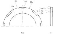
- FIG. 5 is a modified example of the cap described above, (a) is a front view, and (b) is a cross-sectional view.
- the cap 20 is formed by injection molding from a synthetic resin material made of PA (polyamide) 66 to which 30 wt% of a fiber reinforcing material of GF (glass fiber) is added.
- a cylindrical portion 20b extending in the axial direction from the outer diameter portion of the contact portion 20a, and a locking portion 20c protruding inward in the radial direction are provided at the end of the cylindrical portion 20b.
- the locking portion 20c is composed of a plurality of locking pieces formed in the circumferential direction.
- the inner diameter of the locking portion 20c is set to be slightly smaller than the outer diameter of the crimping portion 6, and the cap 20 is attached to the crimping portion 6 by elastically deforming the locking portion 20c.
- the wear resistance is improved, the elastic deformation is facilitated and the assemblability is remarkably improved, and the caulking portion 6 and the shoulder portion 15 of the outer joint member 14 are in contact with each other as in the cap 17 described above. Since the cap 20 slightly moves with a twist of one of the members, the wear of the caulking portion 6 is suppressed, and a sudden slip generated between the caulking portion 6 and the shoulder portion 15 occurs. Can be mitigated and the occurrence of stick-slip noise can be prevented.
- the cap 20 is made of PPA (polyphthalamide), PBT (polybutylene terephthalate), polyphenylene sulfide (PPS), polyetheretherketone (PEEK), thermoplastic polyimide (PI), polyamideimide (PAI) in addition to the materials described above. ) And the like can be illustrated as an injection-moldable synthetic resin.
- PPA polyphthalamide
- PBT polybutylene terephthalate
- PPS polyphenylene sulfide
- PEEK polyetheretherketone
- PI polyetheretherketone
- PAI polyamideimide
- a wheel bearing device includes an inner member composed of a hub wheel and an inner ring, and a constant velocity universal joint, and the inner member and the outer joint member of the constant velocity universal joint are detachably fastened in a butted state. Further, the present invention can be applied to wheel bearing devices having first to third generation structures.
- FIG. 7 is an arrow view along the line VII-VII in FIG. 6.
- Car body mounting flange 56 ... ⁇ ⁇ ⁇ ⁇ ⁇ ⁇ ⁇ ⁇ ⁇ Ball 57 ⁇ ⁇ ⁇ ⁇ ⁇ ⁇ ⁇ ⁇ ⁇ ⁇ ⁇ Inner member 58 ⁇ ⁇ ⁇ ⁇ ⁇ ⁇ ⁇ ⁇ ⁇ ⁇ Inner ring 59 ⁇ ⁇ ⁇ ⁇ ⁇ ⁇ ⁇ ⁇ ⁇ ... Mouse part 60 ......... Shoulder part 60a ......... Contact surface 61 ... Portion 62 ... Outer joint member 63 ... Female serration 64 ...
Abstract
【課題】加締部と外側継手部材の肩部との間で発生する急激なスリップを緩和し、スティックスリップ音の発生を防止した車輪用軸受装置を提供する。 【解決手段】加締部6によって内輪3が固定されたハブ輪2にセレーションを介して外側継手部材14がトルク伝達可能に、かつ軸方向に着脱自在に結合された車輪用軸受装置において、加締部6に鋼板からプレス加工によって形成されたキャップ17が装着され、このキャップ17が、円板状の当接部17aと、この当接部17aの外径部から軸方向に延びる円筒部17bと、この円筒部17bの端部から径方向内方に突出し、内径が加締部6の外径よりも僅かに小径に設定された係止部17cとを備えると共に、当該キャップ17の表面に二硫化モリブデンの浸透拡散メッキ処理による低摩擦皮膜19が形成されている。
Description
本発明は、自動車等の車両の車輪を支持する車輪用軸受装置、詳しくは、車輪用軸受と等速自在継手とを備え、独立懸架式サスペンションに装着された駆動輪(FF車の前輪、FR車あるいはRR車の後輪、および4WD車の全輪)を懸架装置に対して回転自在に支持する車輪用軸受装置に関するものである。
自動車等の車両のエンジン動力を車輪に伝達する動力伝達装置は、エンジンから車輪へ動力を伝達すると共に、悪路走行時における車両のバウンドや車両の旋回時に生じる車輪からの径方向や軸方向変位、およびモーメント変位を許容する必要があるため、例えば、エンジン側と駆動車輪側との間に介装されるドライブシャフトの一端が摺動型の等速自在継手を介してディファレンシャルに連結され、他端が固定型の等速自在継手を含む車輪用軸受装置を介して駆動輪に連結されている。
この車輪用軸受装置として従来から種々の構造のものが提案されているが、例えば図6に示すようなものが知られている。この車輪用軸受装置50は、車輪(図示せず)を一端部に装着するハブ輪51と、このハブ輪51を回転自在に支承する複列の転がり軸受52、およびハブ輪51に連結され、ドライブシャフト(図示せず)の動力をハブ輪51に伝達する固定型の等速自在継手53を備えている。
ハブ輪51は、一端部に車輪を取り付けるための車輪取付フランジ54を一体に有し、外周に内側転走面51aと、この内側転走面51aから軸方向に延びる円筒状の小径段部51bが形成されている。複列の転がり軸受52は、外周に懸架装置(図示せず)に固定される車体取付フランジ55bを一体に有し、内周に複列の外側転走面55a、55aが形成された外方部材55と、この外方部材55に複列のボール56、56を介して内挿される内方部材57とからなる。
内方部材57は、ハブ輪51と、このハブ輪51の小径段部51bに圧入され、外周に内側転走面58aが形成された別体の内輪58とからなる。そして、ハブ輪51の小径段部51bの端部を径方向外方に塑性変形させて形成した加締部51cにより、ハブ輪51に対して内輪58が軸方向に固定されている。
等速自在継手53は、カップ状のマウス部59と、このマウス部59の底部をなす肩部60と、この肩部60から軸方向に延びる軸部61とを一体に有する外側継手部材62を備えている。また、ハブ輪51にこの外側継手部材62がトルク伝達可能に内嵌されている。すなわち、ハブ輪51の内周に雌セレーション63が形成されると共に、外側継手部材62の軸部61の外周に雄セレーション64が形成され、両セレーション63、64が噛合されている。そして、ハブ輪51の加締部51cに肩部60が突き合わされるまで外側継手部材62の軸部61がハブ輪51に内嵌されると共に、軸部61の端部に形成された雄ねじ65に固定ナット66が所定の締め付けトルクで締結され、ハブ輪51と外側継手部材62とが軸方向に着脱自在に結合されている。
こうした車両の車輪には、エンジン低速回転時、例えば車両発進時に、エンジンから摺動型の等速自在継手(図示せず)を介して大きなトルクが負荷され、ドライブシャフトに捩じれが生じることが知られている。その結果、このドライブシャフトを支持する複列の転がり軸受52の内方部材57にも捩じれが生じることになる。このようにドライブシャフトに大きな捩じれが発生した場合、外側継手部材62と内方部材57との当接面60aで急激なスリップによるスティックスリップ音が発生する。
この対策手段として、従来の車輪用軸受装置50において、外側継手部材62の肩部60と当接する部分、すなわち、ハブ輪51の加締部51cが平坦面に形成されると共に、図7に示すように、加締部51cの平坦面の径方向中央部に凹溝67が形成されている。そして、この凹溝67内にグリースが充填されている。これにより、固定ナット66の緊締力に基いて加締部51cに加えられる面圧を小さくすることができ、加締部51cの塑性変形と固定ナット66の弛みを防止すると共に、グリースにより当接面の摩擦係数を低くできるため、この当接面の摩擦エネルギを低減して肩部60と加締部51cとの当接面で急激なスリップによるスティックスリップ音が発生するのを防止することができる。
特開2003-136908号公報
然しながら、この従来の車輪用軸受装置50では、加締部51cの平坦面に凹溝67を形成するための加工が必要となり、コストアップの要因となるばかりか、加締部51cの強度が低下する恐れがある。また、加締部51cの凹溝67内に充填させたグリースが運転中に漏れ出し、長期間に亘ってスティックスリップ音の発生を防止することが困難となる。
本発明は、このような事情に鑑みてなされたもので、加締部と外側継手部材の肩部との間で発生する急激なスリップを緩和し、スティックスリップ音の発生を防止した車輪用軸受装置を提供することを目的としている。
係る目的を達成すべく、本発明のうち請求項1に記載の発明は、内周に複列の外側転走面が一体に形成された外方部材と、一端部に車輪を取り付けるための車輪取付フランジを一体に有し、外周に軸方向に延びる円筒状の小径段部が形成されたハブ輪、およびこのハブ輪の小径段部に圧入された少なくとも一つの内輪からなり、前記複列の外側転走面に対向する複列の内側転走面が形成された内方部材と、この内方部材と前記外方部材の両転走面間に転動自在に収容された複列の転動体と、前記ハブ輪に連結された等速自在継手とを備え、前記小径段部の端部を径方向外方に塑性変形させて形成した加締部により前記内輪が前記ハブ輪に対して軸方向に固定されると共に、前記等速自在継手の外側継手部材が、カップ状のマウス部と、このマウス部の底部をなす肩部と、この肩部から軸方向に延び、前記ハブ輪にセレーションを介してトルク伝達可能に内嵌されたステム部とを一体に有し、前記肩部が前記加締部と突き合わせ状態で、前記ハブ輪と外側継手部材が軸方向に着脱自在に結合された車輪用軸受装置において、前記加締部と肩部との間に低摩擦部材からなるキャップが介装され、このキャップが、円板状の当接部と、この当接部の外径部から軸方向に延びる円筒部と、この円筒部の端部から径方向内方に突出する係止部とを備えると共に、この係止部の内径が前記加締部の外径よりも僅かに小径に設定され、この係止部を弾性変形させることにより当該キャップが前記加締部に装着されている。
このように、加締部によって内輪が固定されたハブ輪にセレーションを介して外側継手部材がトルク伝達可能に、かつ軸方向に着脱自在に結合された車輪用軸受装置において、加締部と肩部との間に低摩擦部材からなるキャップが介装され、このキャップが、円板状の当接部と、この当接部の外径部から軸方向に延びる円筒部と、この円筒部の端部から径方向内方に突出する係止部とを備えると共に、この係止部の内径が加締部の外径よりも僅かに小径に設定され、この係止部を弾性変形させることにより当該キャップが加締部に装着されているので、ドライブシャフトに大きなトルクが負荷され、外側継手部材に大きな捩じれが発生した場合、キャップが加締部と外側継手部材の肩部のうちどちらか一方に一瞬遅れて連れ回りすることになり、当接面の摩擦係数が減少してキャップ自体の摩耗と加締部の摩耗を抑制すると共に、加締部と肩部との間で発生する急激なスリップをこのキャップで緩和し、スティックスリップ音の発生を防止することができる。
また、請求項2に記載の発明のように、前記キャップが鋼板からプレス加工によって形成されると共に、この表面に二硫化モリブデンの浸透拡散メッキ処理による低摩擦皮膜が形成されていれば、密着性や耐久性が良好で、当接面で急激なスリップが発生するこの種の用途には効果的である。
好ましくは、請求項3に記載の発明のように、前記キャップの表面にグリッド状の炭化ケイ素を噴射させて下地処理が施されていれば、低摩擦皮膜の密着性を向上させることができる。
また、請求項4に記載の発明のように、前記キャップが、繊維状の強化材が添加された合成樹脂材から射出成形によって形成されていても良い。
また、請求項5に記載の発明のように、前記キャップの円筒部から係止部に亙る外径部に軸方向に延びるスリットが形成されていても良いし、また、請求項6に記載の発明のように、前記係止部が周方向に複数形成された係止片で構成されていても良い。これにより、係止部の寸法を厳しく規制することなく容易に弾性変形させることができ、キャップの組立性が向上する。
また、請求項7に記載の発明のように、前記キャップと内輪の大端面との間に僅かな軸方向すきまからなるラビリンス構造が形成されていれば、加締部への雨水やダスト等の異物の侵入が防止でき、加締部の発錆を防止して耐久性を向上させることができる。
本発明に係る車輪用軸受装置は、内周に複列の外側転走面が一体に形成された外方部材と、一端部に車輪を取り付けるための車輪取付フランジを一体に有し、外周に軸方向に延びる円筒状の小径段部が形成されたハブ輪、およびこのハブ輪の小径段部に圧入された少なくとも一つの内輪からなり、前記複列の外側転走面に対向する複列の内側転走面が形成された内方部材と、この内方部材と前記外方部材の両転走面間に転動自在に収容された複列の転動体と、前記ハブ輪に連結された等速自在継手とを備え、前記小径段部の端部を径方向外方に塑性変形させて形成した加締部により前記内輪が前記ハブ輪に対して軸方向に固定されると共に、前記等速自在継手の外側継手部材が、カップ状のマウス部と、このマウス部の底部をなす肩部と、この肩部から軸方向に延び、前記ハブ輪にセレーションを介してトルク伝達可能に内嵌されたステム部とを一体に有し、前記肩部が前記加締部と突き合わせ状態で、前記ハブ輪と外側継手部材が軸方向に着脱自在に結合された車輪用軸受装置において、前記加締部と肩部との間に低摩擦部材からなるキャップが介装され、このキャップが、円板状の当接部と、この当接部の外径部から軸方向に延びる円筒部と、この円筒部の端部から径方向内方に突出する係止部とを備えると共に、この係止部の内径が前記加締部の外径よりも僅かに小径に設定され、この係止部を弾性変形させることにより当該キャップが前記加締部に装着されているので、ドライブシャフトに大きなトルクが負荷され、外側継手部材に大きな捩じれが発生した場合、キャップが加締部と外側継手部材の肩部のうちどちらか一方に一瞬遅れて連れ回りすることになり、当接面の摩擦係数が減少してキャップ自体の摩耗と加締部の摩耗を抑制すると共に、加締部と肩部との間で発生する急激なスリップをこのキャップで緩和し、スティックスリップ音の発生を防止することができる。
外周に車体取付フランジを一体に有し、内周に複列の外側転走面が一体に形成された外方部材と、一端部に車輪取付フランジを一体に有し、外周に前記複列の外側転走面の一方に対向する内側転走面と、この内側転走面から軸方向に延びる円筒状の小径段部が形成されたハブ輪、およびこのハブ輪の小径段部に圧入され、外周に前記複列の外側転走面の他方に対向する内側転走面が形成された内輪からなる内方部材と、この内方部材と前記外方部材の両転走面間に転動自在に収容された複列の転動体と、前記ハブ輪に連結された等速自在継手とを備え、前記小径段部の端部を径方向外方に塑性変形させて形成した加締部により前記内輪が前記ハブ輪に対して軸方向に固定されると共に、前記等速自在継手の外側継手部材が、カップ状のマウス部と、このマウス部の底部をなす肩部と、この肩部から軸方向に延び、前記ハブ輪にセレーションを介してトルク伝達可能に内嵌されたステム部とを一体に有し、前記肩部が前記加締部と突き合わせ状態で、前記ハブ輪と外側継手部材が軸方向に着脱自在に結合された車輪用軸受装置において、前記加締部に鋼板からプレス加工によって形成されたキャップが装着され、このキャップが、円板状の当接部と、この当接部の外径部から軸方向に延びる円筒部と、この円筒部の端部から径方向内方に突出し、内径が前記加締部の外径よりも僅かに小径に設定された係止部とを備えると共に、当該キャップの表面に二硫化モリブデンの浸透拡散メッキ処理による低摩擦皮膜が形成されている。
以下、本発明の実施の形態を図面に基いて詳細に説明する。
図1は、本発明に係る車輪用軸受装置の一実施形態を示す縦断面図、図2は、図1の要部拡大図、図3は、本発明に係るキャップが装着されたサンプルの試験における波形を示すグラフ、図4は、比較例となるサンプルの試験における波形を示すグラフ、図5(a)は、図2のキャップの変形例を示す正面図、(b)は、(a)の横断面図である。なお、以下の説明では、車両に組み付けた状態で車両の外側寄りとなる側をアウター側(図1の左側)、中央寄り側をインナー側(図1の右側)という。
図1は、本発明に係る車輪用軸受装置の一実施形態を示す縦断面図、図2は、図1の要部拡大図、図3は、本発明に係るキャップが装着されたサンプルの試験における波形を示すグラフ、図4は、比較例となるサンプルの試験における波形を示すグラフ、図5(a)は、図2のキャップの変形例を示す正面図、(b)は、(a)の横断面図である。なお、以下の説明では、車両に組み付けた状態で車両の外側寄りとなる側をアウター側(図1の左側)、中央寄り側をインナー側(図1の右側)という。
この車輪用軸受装置は駆動輪用の第3世代と呼称され、内方部材1と外方部材10、および両部材1、10間に転動自在に収容された複列の転動体(ボール)8、8とを備え、等速自在継手13が着脱自在に結合されている。内方部材1は、ハブ輪2と、このハブ輪2に圧入された内輪3とからなる。
ハブ輪2は、アウター側の端部に車輪(図示せず)を取り付けるための車輪取付フランジ4を一体に有し、外周に一方(アウター側)の内側転走面2aと、この内側転走面2aから軸方向に延びる円筒状の小径段部2bが形成され、内周にトルク伝達用のセレーション(またはスプライン)2cが形成されている。車輪取付フランジ4の円周等配位置には車輪を取り付けるハブボルト5が植設されている。
ハブ輪2はS53C等の炭素0.40~0.80重量%を含む中高炭素鋼で形成され、内側転走面2aをはじめ、後述するアウター側のシール11が摺接するシールランド部となる基部7から小径段部2bに亙り高周波焼入れによって表面硬さを58~64HRCの範囲に硬化処理が施されている。そして、外周に他方(インナー側)の内側転走面3aが形成された内輪3がハブ輪2の小径段部2bに所定のシメシロを介して圧入され、小径段部2bの端部を径方向外方に塑性変形させて形成した加締部6によって内輪3が軸方向に固定されている。この加締6の端面は平坦面に形成され、軸力によって加締部6に加えられる面圧を小さくすることができ、加締部6の塑性変形と摩耗を防止することができる。
一方、内輪3および転動体8はSUJ2等の高炭素クロム鋼で形成され、外周に他方(インナー側)の内側転走面3aが形成されてズブ焼入れにより芯部まで58~64HRCの範囲に硬化処理されている。
外方部材10は、外周に車体(図示せず)に取り付けるための車体取付フランジ10bを一体に有し、内周に前記内方部材1の内側転走面2a、3aに対向する複列の外側転走面10a、10aが一体に形成されている。外方部材10はS53C等の炭素0.40~0.80重量%を含む中高炭素鋼で形成され、複列の外側転走面10a、10aが高周波焼入れによって表面硬さを58~64HRCの範囲に硬化処理が施されている。そして、それぞれの転走面10a、2aと10a、3a間に複列の転動体8、8が保持器9、9を介して転動自在に収容されている。また、外方部材10と内方部材1との間に形成される環状空間の開口部にはシール11、12が装着され、軸受内部に封入された潤滑グリースの漏洩を防止すると共に、外部から軸受内部に雨水やダスト等が侵入するのを防止している。
なお、本実施形態では、転動体8にボールを使用した複列アンギュラ玉軸受を例示したが、これに限らず、例えば、転動体8に円すいころを用いた複列の円すいころ軸受であっても良い。また、ここでは、ハブ輪2の外周に一方の内側転走面2aが直接形成された、所謂第3世代構造を例示したが、図示はしないが、ハブ輪の小径段部に一対の内輪が圧入された、所謂第1または第2世代構造であっても良い。
等速自在継手13は、外側継手部材14と、図示はしないが継手内輪とケージおよびトルク伝達ボールを備えている。外側継手部材14はS53C等の炭素0.40~0.80重量%を含む中高炭素鋼で形成され、カップ状のマウス部(図示せず)と、このマウス部の底部をなす肩部15と、この肩部15から軸方向に延びるステム部16を一体に有している。ステム部16は、外周にハブ輪2のセレーション2cに係合するセレーション(またはスプライン)16aと、このセレーション16aの端部に雄ねじ16bが形成されている。外側継手部材14のステム部16は、後述するキャップ17を介して肩部15が加締部6に衝合するまでハブ輪2に嵌挿され、加締部6と肩部15とが突き合わせ状態で、雄ねじ16bに固定ナット18が所定の締付トルクで締結され、ハブ輪2と外側継手部材14が軸方向に着脱自在に結合されている。
ここで、加締部6にキャップ17が装着されている。このキャップ17は、耐食性を有する鋼板、例えば、防錆処理された冷間圧延鋼鈑(JIS規格のSPCC系)やオーステナイト系ステンレス鋼鈑(JIS規格のSUS304系)等をプレス加工にて断面が略L字状に形成され、図2に拡大して示すように、円板状の当接部17aと、この当接部17aの外径部から軸方向に延びる円筒部17bと、この円筒部17bの端部から径方向内方に折曲された係止部17cとを備えている。この係止部17cの内径は加締部6の外径よりも僅かに小径に設定され、この係止部17cを弾性変形させることによりキャップ17が加締部6に装着されている。また、キャップ17は、内輪3の大端面3bに最大1mmの軸方向すきまを介して対峙し、ラビリンス構造を有している。これにより、キャップ17を加締部6にワンタッチで装着することができ、組立工程において加締部6からキャップ17が脱落するのを防止することができると共に、ラビリンス構造により、加締部6への雨水やダスト等の異物の侵入が防止でき、加締部6の発錆を防止して耐久性を向上させることができる。
なお、図示はしないが、キャップ17の円筒部17bから係止部17cに亙る外径部に軸方向に延びるスリットが形成されていれば、係止部17cの寸法を厳しく規制することなく弾性変形を容易にすることができ、キャップ17の組立性が向上する。
そして、本実施形態では、キャップ17の表面に膜厚0.3~1.0mmの低摩擦皮膜19が形成されている。この低摩擦皮膜19は、二硫化モリブデンからなる粉体をキャップ17の表面にショットピーニングしてその元素を拡散浸透させた、所謂PIP処理(浸透拡散メッキ処理)によって形成されている。ここで、この処理は、鱗片状の粒形状をなす粒度5μm程度の二硫化モリブデンを噴射圧力0.5MPaにて略20sec.ショットピーニングすることによって行われる。なお、低摩擦皮膜19の密着性を向上させるために、粒度番号400(40~50μm)のグリッド状のSiC(炭化ケイ素)をキャップ17の表面に噴射させて下地処理を行うのが好ましい。
こうした低摩擦皮膜19が形成されたキャップ17が加締部6に装着され、このキャップ17を介して加締部6と肩部15が突き合わせ状態で、ハブ輪2と外側継手部材14が軸方向に着脱自在に結合されているので、ドライブシャフト(図示せず)に大きなトルクが負荷され、外側継手部材14に大きな捩じれが発生した場合、キャップ17が加締部6と外側継手部材14の肩部15のうちどちらか一方に一瞬遅れて連れ回りすることになる。したがって、当接面の摩擦係数が減少してキャップ17自体の摩耗と加締部6の摩耗を抑制すると共に、加締部6と肩部15との間で発生する急激なスリップをこのキャップ17で緩和し、スティックスリップ音の発生を防止することができる。
本出願人が実施した異音発生試験の結果を図3および図4に示す。図3は、本発明に係る低摩擦皮膜19、すなわち、表面に二硫化モリブデンをPIP処理したキャップ17が装着されたサンプルの波形グラフを示し、図4は、それ以外のキャップが装着されたサンプル(代表例)の波形グラフを示している。ここで、試験条件は、設定軸力が50kN、入力トルクが±0.6kN・m、周波数が0.8Hz、運転回数が3.6万回である。そして、判定基準は、初期および耐久試験後に77db以上の異音の有無をもって合否を決定した。なお、実施した各サンプルの試験結果を表1に示す。

図3に示すように、本発明に係るキャップ17が装着されたサンプルでは、外側継手部材14と内輪3との加速度が略一致すると共に、内輪3の加速度に大きな変動がなく、異音発生がなかった。一方、図4に示す波形グラフから明らかなように、比較例のサンプルでは、外側継手部材14と内輪3との加速度が異なると共に、随所で内輪3の加速度に大きな変動があり異音発生が認められた。
また、MoS2をPIP処理した低摩擦皮膜19は、Snのショット品に比べ密着性や耐久性が良好で、表1からも判るように、当接面で急激なスリップが発生するこの種の用途には効果的と考えられる。
図5は、前述したキャップの変形例で、(a)は、正面図、(b)は、横断面図を示す。
このキャップ20は、GF(ガラスファイバー)の繊維状の強化材が30wt%添加されたPA(ポリアミド)66からなる合成樹脂材から射出成形によって形成され、円板状の当接部20aと、この当接部20aの外径部から軸方向に延びる円筒部20bと、この円筒部20bの端部に径方向内方に突出する係止部20cとを備えている。この係止部20cは、周方向に複数形成された係止片で構成されている。なお、係止部20cの内径は加締部6の外径よりも僅かに小径に設定され、係止部20cを弾性変形させてキャップ20を加締部6に装着される。
このキャップ20は、GF(ガラスファイバー)の繊維状の強化材が30wt%添加されたPA(ポリアミド)66からなる合成樹脂材から射出成形によって形成され、円板状の当接部20aと、この当接部20aの外径部から軸方向に延びる円筒部20bと、この円筒部20bの端部に径方向内方に突出する係止部20cとを備えている。この係止部20cは、周方向に複数形成された係止片で構成されている。なお、係止部20cの内径は加締部6の外径よりも僅かに小径に設定され、係止部20cを弾性変形させてキャップ20を加締部6に装着される。
これにより、耐摩耗性の向上と、弾性変形が容易になって組立性が格段に向上すると共に、前述したキャップ17と同様、加締部6と外側継手部材14の肩部15とが当接せず、キャップ20がどちらか一方の部材の捩れに伴って遅れて微動するため、加締部6の摩耗を抑制すると共に、加締部6と肩部15との間で発生する急激なスリップを緩和し、スティックスリップ音の発生を防止することができる。なお、キャップ20は前述した材質以外に、PPA(ポリフタルアミド)、PBT(ポリブチレンテレフタレート)、ポリフェニレンサルファイド(PPS)、ポリエーテルエーテルケトン(PEEK)、熱可塑性ポリイミド(PI)、ポリアミドイミド(PAI)等の射出成形可能な合成樹脂を例示することができる。
以上、本発明の実施の形態について説明を行ったが、本発明はこうした実施の形態に何等限定されるものではなく、あくまで例示であって、本発明の要旨を逸脱しない範囲内において、さらに種々なる形態で実施し得ることは勿論のことであり、本発明の範囲は、特許請求の範囲の記載によって示され、さらに特許請求の範囲に記載の均等の意味、および範囲内のすべての変更を含む。
本発明に係る車輪用軸受装置は、ハブ輪と内輪からなる内方部材と等速自在継手とを備え、内方部材と等速自在継手の外側継手部材とが突き合わせ状態で分離可能に締結された第1乃至第3世代構造の車輪用軸受装置に適用できる。
1・・・・・・・・・・・・・内方部材
2・・・・・・・・・・・・・ハブ輪
2a、3a・・・・・・・・・内側転走面
2b・・・・・・・・・・・・小径段部
2c、16a・・・・・・・・セレーション
3・・・・・・・・・・・・・内輪
3b・・・・・・・・・・・・内輪の大端面
4・・・・・・・・・・・・・車輪取付フランジ
5・・・・・・・・・・・・・ハブボルト
6・・・・・・・・・・・・・加締部
7・・・・・・・・・・・・・基部
8・・・・・・・・・・・・・転動体
9・・・・・・・・・・・・・保持器
10・・・・・・・・・・・・外方部材
10a・・・・・・・・・・・外側転走面
10b・・・・・・・・・・・車体取付フランジ
11、12・・・・・・・・・シール
13・・・・・・・・・・・・等速自在継手
14・・・・・・・・・・・・外側継手部材
15・・・・・・・・・・・・肩部
16・・・・・・・・・・・・ステム部
16b・・・・・・・・・・・雄ねじ
17、20・・・・・・・・・キャップ
17a、20a・・・・・・・当接部
17b、20b・・・・・・・円筒部
17c、20c・・・・・・・係止部
18・・・・・・・・・・・・固定ナット
19・・・・・・・・・・・・低摩擦皮膜
50・・・・・・・・・・・・車輪用軸受装置
51・・・・・・・・・・・・ハブ輪
51a、58a・・・・・・・内側転走面
51b・・・・・・・・・・・小径段部
51c・・・・・・・・・・・加締部
52・・・・・・・・・・・・複列の転がり軸受
53・・・・・・・・・・・・等速自在継手
54・・・・・・・・・・・・車輪取付フランジ
55・・・・・・・・・・・・外方部材
55a・・・・・・・・・・・外側転走面
55b・・・・・・・・・・・車体取付フランジ
56・・・・・・・・・・・・ボール
57・・・・・・・・・・・・内方部材
58・・・・・・・・・・・・内輪
59・・・・・・・・・・・・マウス部
60・・・・・・・・・・・・肩部
60a・・・・・・・・・・・当接面
61・・・・・・・・・・・・軸部
62・・・・・・・・・・・・外側継手部材
63・・・・・・・・・・・・雌セレーション
64・・・・・・・・・・・・雄セレーション
65・・・・・・・・・・・・雄ねじ
66・・・・・・・・・・・・固定ナット
67・・・・・・・・・・・・凹溝
Claims (7)
- 内周に複列の外側転走面が一体に形成された外方部材と、
一端部に車輪を取り付けるための車輪取付フランジを一体に有し、外周に軸方向に延びる円筒状の小径段部が形成されたハブ輪、およびこのハブ輪の小径段部に圧入された少なくとも一つの内輪からなり、前記複列の外側転走面に対向する複列の内側転走面が形成された内方部材と、
この内方部材と前記外方部材の両転走面間に転動自在に収容された複列の転動体と、
前記ハブ輪に連結された等速自在継手とを備え、
前記小径段部の端部を径方向外方に塑性変形させて形成した加締部により前記内輪が前記ハブ輪に対して軸方向に固定されると共に、
前記等速自在継手の外側継手部材が、カップ状のマウス部と、このマウス部の底部をなす肩部と、この肩部から軸方向に延び、前記ハブ輪にセレーションを介してトルク伝達可能に内嵌されたステム部とを一体に有し、前記肩部が前記加締部と突き合わせ状態で、前記ハブ輪と外側継手部材が軸方向に着脱自在に結合された車輪用軸受装置において、
前記加締部と肩部との間に低摩擦部材からなるキャップが介装され、このキャップが、円板状の当接部と、この当接部の外径部から軸方向に延びる円筒部と、この円筒部の端部から径方向内方に突出する係止部とを備えると共に、この係止部の内径が前記加締部の外径よりも僅かに小径に設定され、この係止部を弾性変形させることにより当該キャップが前記加締部に装着されていることを特徴とする車輪用軸受装置。 - 前記キャップが鋼板からプレス加工によって形成されると共に、この表面に二硫化モリブデンの浸透拡散メッキ処理による低摩擦皮膜が形成されている請求項1に記載の車輪用軸受装置。
- 前記キャップの表面にグリッド状の炭化ケイ素を噴射させて下地処理が施されている請求項2に記載の車輪用軸受装置。
- 前記キャップが、繊維状の強化材が添加された合成樹脂材から射出成形によって形成されている請求項1に記載の車輪用軸受装置。
- 前記キャップの円筒部から係止部に亙る外径部に軸方向に延びるスリットが形成されている請求項1乃至4いずれかに記載の車輪用軸受装置。
- 前記係止部が周方向に複数形成された係止片で構成されている請求項1乃至4いずれかに記載の車輪用軸受装置。
- 前記キャップと内輪の大端面との間に僅かな軸方向すきまからなるラビリンス構造が形成されている請求項1乃至6いずれかに記載の車輪用軸受装置。
Priority Applications (2)
| Application Number | Priority Date | Filing Date | Title |
|---|---|---|---|
| CN2009801082595A CN102015326B (zh) | 2008-03-10 | 2009-02-24 | 车轮用轴承装置 |
| US12/879,344 US8313245B2 (en) | 2008-03-10 | 2010-09-10 | Wheel bearing apparatus for a vehicle |
Applications Claiming Priority (2)
| Application Number | Priority Date | Filing Date | Title |
|---|---|---|---|
| JP2008-059720 | 2008-03-10 | ||
| JP2008059720A JP5595641B2 (ja) | 2008-03-10 | 2008-03-10 | 車輪用軸受装置 |
Related Child Applications (1)
| Application Number | Title | Priority Date | Filing Date |
|---|---|---|---|
| US12/879,344 Continuation US8313245B2 (en) | 2008-03-10 | 2010-09-10 | Wheel bearing apparatus for a vehicle |
Publications (1)
| Publication Number | Publication Date |
|---|---|
| WO2009113252A1 true WO2009113252A1 (ja) | 2009-09-17 |
Family
ID=41064925
Family Applications (1)
| Application Number | Title | Priority Date | Filing Date |
|---|---|---|---|
| PCT/JP2009/000792 WO2009113252A1 (ja) | 2008-03-10 | 2009-02-24 | 車輪用軸受装置 |
Country Status (4)
| Country | Link |
|---|---|
| US (1) | US8313245B2 (ja) |
| JP (1) | JP5595641B2 (ja) |
| CN (1) | CN102015326B (ja) |
| WO (1) | WO2009113252A1 (ja) |
Cited By (1)
| Publication number | Priority date | Publication date | Assignee | Title |
|---|---|---|---|---|
| US8944196B2 (en) | 2010-03-30 | 2015-02-03 | Ntn Corporation | Wheel bearing apparatus incorporated with an in-wheel motor |
Families Citing this family (4)
| Publication number | Priority date | Publication date | Assignee | Title |
|---|---|---|---|---|
| JP2012001010A (ja) * | 2010-06-14 | 2012-01-05 | Ntn Corp | 車輪用軸受装置 |
| ITTO20130507A1 (it) * | 2013-06-19 | 2014-12-20 | Skf Ab | Dispositivo flessibile di tenuta per gruppi mozzi ruota connessi a giunti omocinetici |
| JP6449689B2 (ja) * | 2015-03-11 | 2019-01-09 | Ntn株式会社 | 車輪用軸受装置 |
| CN114033810A (zh) * | 2021-11-11 | 2022-02-11 | 上海纳铁福传动系统有限公司 | 一种等速万向节传动轴与轮毂轴承单元的扭矩传递结构 |
Citations (6)
| Publication number | Priority date | Publication date | Assignee | Title |
|---|---|---|---|---|
| JP2005145315A (ja) * | 2003-11-18 | 2005-06-09 | Ntn Corp | 駆動車輪用軸受装置 |
| JP2006188187A (ja) * | 2005-01-07 | 2006-07-20 | Ntn Corp | 車輪用軸受装置 |
| JP2006275174A (ja) * | 2005-03-29 | 2006-10-12 | Ntn Corp | 駆動車輪用軸受装置 |
| JP2007276764A (ja) * | 2006-03-13 | 2007-10-25 | Ntn Corp | 駆動車輪用軸受装置 |
| JP2007292203A (ja) * | 2006-04-25 | 2007-11-08 | Ntn Corp | 駆動車輪用軸受装置 |
| JP2007298092A (ja) * | 2006-04-28 | 2007-11-15 | Ntn Corp | 駆動車輪用軸受装置 |
Family Cites Families (10)
| Publication number | Priority date | Publication date | Assignee | Title |
|---|---|---|---|---|
| US3300258A (en) * | 1964-03-05 | 1967-01-24 | Teleflex Inc | Bearing and method for making same |
| JPS5285617A (en) * | 1976-01-12 | 1977-07-16 | Riken Corp | Sliding member surface layer |
| JPH0718906U (ja) * | 1993-09-17 | 1995-04-04 | 光洋精工株式会社 | 車輪用軸受装置 |
| JPH07317753A (ja) * | 1994-05-31 | 1995-12-08 | Ntn Corp | 車輪用軸受ユニット |
| ITTO20010849A1 (it) * | 2001-09-06 | 2003-03-06 | Skf Ind Spa | Dispositivo di tenuta per cuscinetti. |
| JP2003136908A (ja) | 2001-10-30 | 2003-05-14 | Nsk Ltd | 車輪駆動用軸受ユニット |
| EP1526297B1 (de) * | 2003-10-24 | 2007-03-28 | GKN Driveline International GmbH | Gelenkaussenteil mit Abstützscheibe |
| JP2005147298A (ja) * | 2003-11-18 | 2005-06-09 | Ntn Corp | 車輪用軸受装置 |
| JP2005324714A (ja) * | 2004-05-17 | 2005-11-24 | Ntn Corp | 車輪用軸受装置 |
| JP5184820B2 (ja) | 2007-06-01 | 2013-04-17 | Ntn株式会社 | 車輪用軸受装置 |
-
2008
- 2008-03-10 JP JP2008059720A patent/JP5595641B2/ja active Active
-
2009
- 2009-02-24 WO PCT/JP2009/000792 patent/WO2009113252A1/ja active Application Filing
- 2009-02-24 CN CN2009801082595A patent/CN102015326B/zh not_active Expired - Fee Related
-
2010
- 2010-09-10 US US12/879,344 patent/US8313245B2/en not_active Expired - Fee Related
Patent Citations (6)
| Publication number | Priority date | Publication date | Assignee | Title |
|---|---|---|---|---|
| JP2005145315A (ja) * | 2003-11-18 | 2005-06-09 | Ntn Corp | 駆動車輪用軸受装置 |
| JP2006188187A (ja) * | 2005-01-07 | 2006-07-20 | Ntn Corp | 車輪用軸受装置 |
| JP2006275174A (ja) * | 2005-03-29 | 2006-10-12 | Ntn Corp | 駆動車輪用軸受装置 |
| JP2007276764A (ja) * | 2006-03-13 | 2007-10-25 | Ntn Corp | 駆動車輪用軸受装置 |
| JP2007292203A (ja) * | 2006-04-25 | 2007-11-08 | Ntn Corp | 駆動車輪用軸受装置 |
| JP2007298092A (ja) * | 2006-04-28 | 2007-11-15 | Ntn Corp | 駆動車輪用軸受装置 |
Cited By (1)
| Publication number | Priority date | Publication date | Assignee | Title |
|---|---|---|---|---|
| US8944196B2 (en) | 2010-03-30 | 2015-02-03 | Ntn Corporation | Wheel bearing apparatus incorporated with an in-wheel motor |
Also Published As
| Publication number | Publication date |
|---|---|
| US20100329598A1 (en) | 2010-12-30 |
| CN102015326B (zh) | 2013-01-02 |
| CN102015326A (zh) | 2011-04-13 |
| JP2009214676A (ja) | 2009-09-24 |
| US8313245B2 (en) | 2012-11-20 |
| JP5595641B2 (ja) | 2014-09-24 |
Similar Documents
| Publication | Publication Date | Title |
|---|---|---|
| JP5184820B2 (ja) | 車輪用軸受装置 | |
| JP4557223B2 (ja) | 駆動車輪用軸受装置 | |
| JP4526998B2 (ja) | 駆動車輪用軸受装置 | |
| WO2009113252A1 (ja) | 車輪用軸受装置 | |
| JP5134356B2 (ja) | 車輪用軸受装置 | |
| JP6629545B2 (ja) | 車輪用軸受装置 | |
| WO2014109331A1 (ja) | 車輪用軸受装置 | |
| JP6309228B2 (ja) | 車輪用軸受装置の製造方法 | |
| JP2009287699A (ja) | 車輪用軸受装置 | |
| JP4868891B2 (ja) | 車輪用軸受装置 | |
| WO2007122809A1 (ja) | 車輪用軸受装置 | |
| JP6534458B2 (ja) | 密封装置およびこれを備えた車輪用軸受装置 | |
| JP5415773B2 (ja) | 車輪用軸受装置 | |
| JP2008163979A (ja) | 車輪用軸受装置 | |
| JP2004084763A (ja) | 駆動車輪用軸受 | |
| JP6661308B2 (ja) | 車輪用軸受装置 | |
| JP2009257375A (ja) | 車輪用軸受装置 | |
| JP2013166487A (ja) | 車輪用軸受装置 | |
| JP2013040664A (ja) | 車輪用軸受装置 | |
| JP2006297963A (ja) | 駆動車輪用軸受装置 | |
| JP4371428B2 (ja) | 車輪用軸受およびそれを備えた車輪用軸受装置 | |
| JP2009286310A (ja) | 駆動車輪用軸受装置 | |
| JP2011005956A (ja) | 車輪用軸受装置 | |
| JP2010023604A (ja) | 車輪用軸受装置 | |
| JP2010042763A (ja) | 車輪用軸受装置 |
Legal Events
| Date | Code | Title | Description |
|---|---|---|---|
| WWE | Wipo information: entry into national phase |
Ref document number: 200980108259.5 Country of ref document: CN |
|
| 121 | Ep: the epo has been informed by wipo that ep was designated in this application |
Ref document number: 09720420 Country of ref document: EP Kind code of ref document: A1 |
|
| NENP | Non-entry into the national phase |
Ref country code: DE |
|
| 122 | Ep: pct application non-entry in european phase |
Ref document number: 09720420 Country of ref document: EP Kind code of ref document: A1 |