WO2009113252A1 - Dispositif de palier de roue - Google Patents
Dispositif de palier de roue Download PDFInfo
- Publication number
- WO2009113252A1 WO2009113252A1 PCT/JP2009/000792 JP2009000792W WO2009113252A1 WO 2009113252 A1 WO2009113252 A1 WO 2009113252A1 JP 2009000792 W JP2009000792 W JP 2009000792W WO 2009113252 A1 WO2009113252 A1 WO 2009113252A1
- Authority
- WO
- WIPO (PCT)
- Prior art keywords
- cap
- wheel
- bearing device
- wheel bearing
- axial direction
- Prior art date
Links
Images


Classifications
-
- B—PERFORMING OPERATIONS; TRANSPORTING
- B60—VEHICLES IN GENERAL
- B60B—VEHICLE WHEELS; CASTORS; AXLES FOR WHEELS OR CASTORS; INCREASING WHEEL ADHESION
- B60B27/00—Hubs
- B60B27/0015—Hubs for driven wheels
- B60B27/0021—Hubs for driven wheels characterised by torque transmission means from drive axle
- B60B27/0026—Hubs for driven wheels characterised by torque transmission means from drive axle of the radial type, e.g. splined key
-
- B—PERFORMING OPERATIONS; TRANSPORTING
- B60—VEHICLES IN GENERAL
- B60B—VEHICLE WHEELS; CASTORS; AXLES FOR WHEELS OR CASTORS; INCREASING WHEEL ADHESION
- B60B27/00—Hubs
- B60B27/0005—Hubs with ball bearings
-
- B—PERFORMING OPERATIONS; TRANSPORTING
- B60—VEHICLES IN GENERAL
- B60B—VEHICLE WHEELS; CASTORS; AXLES FOR WHEELS OR CASTORS; INCREASING WHEEL ADHESION
- B60B27/00—Hubs
- B60B27/0078—Hubs characterised by the fixation of bearings
- B60B27/0084—Hubs characterised by the fixation of bearings caulking to fix inner race
-
- B—PERFORMING OPERATIONS; TRANSPORTING
- B60—VEHICLES IN GENERAL
- B60B—VEHICLE WHEELS; CASTORS; AXLES FOR WHEELS OR CASTORS; INCREASING WHEEL ADHESION
- B60B7/00—Wheel cover discs, rings, or the like, for ornamenting, protecting, venting, or obscuring, wholly or in part, the wheel body, rim, hub, or tyre sidewall, e.g. wheel cover discs, wheel cover discs with cooling fins
- B60B7/06—Fastening arrangements therefor
- B60B7/061—Fastening arrangements therefor characterised by the part of the wheels to which the discs, rings or the like are mounted
- B60B7/066—Fastening arrangements therefor characterised by the part of the wheels to which the discs, rings or the like are mounted to the hub
-
- F—MECHANICAL ENGINEERING; LIGHTING; HEATING; WEAPONS; BLASTING
- F16—ENGINEERING ELEMENTS AND UNITS; GENERAL MEASURES FOR PRODUCING AND MAINTAINING EFFECTIVE FUNCTIONING OF MACHINES OR INSTALLATIONS; THERMAL INSULATION IN GENERAL
- F16C—SHAFTS; FLEXIBLE SHAFTS; ELEMENTS OR CRANKSHAFT MECHANISMS; ROTARY BODIES OTHER THAN GEARING ELEMENTS; BEARINGS
- F16C35/00—Rigid support of bearing units; Housings, e.g. caps, covers
- F16C35/04—Rigid support of bearing units; Housings, e.g. caps, covers in the case of ball or roller bearings
- F16C35/06—Mounting or dismounting of ball or roller bearings; Fixing them onto shaft or in housing
- F16C35/063—Fixing them on the shaft
-
- F—MECHANICAL ENGINEERING; LIGHTING; HEATING; WEAPONS; BLASTING
- F16—ENGINEERING ELEMENTS AND UNITS; GENERAL MEASURES FOR PRODUCING AND MAINTAINING EFFECTIVE FUNCTIONING OF MACHINES OR INSTALLATIONS; THERMAL INSULATION IN GENERAL
- F16C—SHAFTS; FLEXIBLE SHAFTS; ELEMENTS OR CRANKSHAFT MECHANISMS; ROTARY BODIES OTHER THAN GEARING ELEMENTS; BEARINGS
- F16C35/00—Rigid support of bearing units; Housings, e.g. caps, covers
- F16C35/04—Rigid support of bearing units; Housings, e.g. caps, covers in the case of ball or roller bearings
- F16C35/06—Mounting or dismounting of ball or roller bearings; Fixing them onto shaft or in housing
- F16C35/07—Fixing them on the shaft or housing with interposition of an element
- F16C35/073—Fixing them on the shaft or housing with interposition of an element between shaft and inner race ring
-
- F—MECHANICAL ENGINEERING; LIGHTING; HEATING; WEAPONS; BLASTING
- F16—ENGINEERING ELEMENTS AND UNITS; GENERAL MEASURES FOR PRODUCING AND MAINTAINING EFFECTIVE FUNCTIONING OF MACHINES OR INSTALLATIONS; THERMAL INSULATION IN GENERAL
- F16C—SHAFTS; FLEXIBLE SHAFTS; ELEMENTS OR CRANKSHAFT MECHANISMS; ROTARY BODIES OTHER THAN GEARING ELEMENTS; BEARINGS
- F16C19/00—Bearings with rolling contact, for exclusively rotary movement
- F16C19/02—Bearings with rolling contact, for exclusively rotary movement with bearing balls essentially of the same size in one or more circular rows
- F16C19/14—Bearings with rolling contact, for exclusively rotary movement with bearing balls essentially of the same size in one or more circular rows for both radial and axial load
- F16C19/18—Bearings with rolling contact, for exclusively rotary movement with bearing balls essentially of the same size in one or more circular rows for both radial and axial load with two or more rows of balls
- F16C19/181—Bearings with rolling contact, for exclusively rotary movement with bearing balls essentially of the same size in one or more circular rows for both radial and axial load with two or more rows of balls with angular contact
- F16C19/183—Bearings with rolling contact, for exclusively rotary movement with bearing balls essentially of the same size in one or more circular rows for both radial and axial load with two or more rows of balls with angular contact with two rows at opposite angles
- F16C19/184—Bearings with rolling contact, for exclusively rotary movement with bearing balls essentially of the same size in one or more circular rows for both radial and axial load with two or more rows of balls with angular contact with two rows at opposite angles in O-arrangement
- F16C19/186—Bearings with rolling contact, for exclusively rotary movement with bearing balls essentially of the same size in one or more circular rows for both radial and axial load with two or more rows of balls with angular contact with two rows at opposite angles in O-arrangement with three raceways provided integrally on parts other than race rings, e.g. third generation hubs
-
- F—MECHANICAL ENGINEERING; LIGHTING; HEATING; WEAPONS; BLASTING
- F16—ENGINEERING ELEMENTS AND UNITS; GENERAL MEASURES FOR PRODUCING AND MAINTAINING EFFECTIVE FUNCTIONING OF MACHINES OR INSTALLATIONS; THERMAL INSULATION IN GENERAL
- F16C—SHAFTS; FLEXIBLE SHAFTS; ELEMENTS OR CRANKSHAFT MECHANISMS; ROTARY BODIES OTHER THAN GEARING ELEMENTS; BEARINGS
- F16C19/00—Bearings with rolling contact, for exclusively rotary movement
- F16C19/52—Bearings with rolling contact, for exclusively rotary movement with devices affected by abnormal or undesired conditions
- F16C19/527—Bearings with rolling contact, for exclusively rotary movement with devices affected by abnormal or undesired conditions related to vibration and noise
-
- F—MECHANICAL ENGINEERING; LIGHTING; HEATING; WEAPONS; BLASTING
- F16—ENGINEERING ELEMENTS AND UNITS; GENERAL MEASURES FOR PRODUCING AND MAINTAINING EFFECTIVE FUNCTIONING OF MACHINES OR INSTALLATIONS; THERMAL INSULATION IN GENERAL
- F16C—SHAFTS; FLEXIBLE SHAFTS; ELEMENTS OR CRANKSHAFT MECHANISMS; ROTARY BODIES OTHER THAN GEARING ELEMENTS; BEARINGS
- F16C2326/00—Articles relating to transporting
- F16C2326/01—Parts of vehicles in general
- F16C2326/02—Wheel hubs or castors
-
- F—MECHANICAL ENGINEERING; LIGHTING; HEATING; WEAPONS; BLASTING
- F16—ENGINEERING ELEMENTS AND UNITS; GENERAL MEASURES FOR PRODUCING AND MAINTAINING EFFECTIVE FUNCTIONING OF MACHINES OR INSTALLATIONS; THERMAL INSULATION IN GENERAL
- F16D—COUPLINGS FOR TRANSMITTING ROTATION; CLUTCHES; BRAKES
- F16D3/00—Yielding couplings, i.e. with means permitting movement between the connected parts during the drive
- F16D3/16—Universal joints in which flexibility is produced by means of pivots or sliding or rolling connecting parts
- F16D3/20—Universal joints in which flexibility is produced by means of pivots or sliding or rolling connecting parts one coupling part entering a sleeve of the other coupling part and connected thereto by sliding or rolling members
- F16D3/22—Universal joints in which flexibility is produced by means of pivots or sliding or rolling connecting parts one coupling part entering a sleeve of the other coupling part and connected thereto by sliding or rolling members the rolling members being balls, rollers, or the like, guided in grooves or sockets in both coupling parts
- F16D3/223—Universal joints in which flexibility is produced by means of pivots or sliding or rolling connecting parts one coupling part entering a sleeve of the other coupling part and connected thereto by sliding or rolling members the rolling members being balls, rollers, or the like, guided in grooves or sockets in both coupling parts the rolling members being guided in grooves in both coupling parts
- F16D2003/22326—Attachments to the outer joint member, i.e. attachments to the exterior of the outer joint member or to the shaft of the outer joint member
Definitions
- the present invention relates to a wheel bearing device for supporting a wheel of a vehicle such as an automobile, and more specifically, a drive wheel (a front wheel of an FF vehicle, FR) provided with a wheel bearing and a constant velocity universal joint and mounted on an independent suspension type suspension.
- the present invention relates to a wheel bearing device that rotatably supports a rear wheel of a car or an RR car and all wheels of a 4WD car) with respect to a suspension device.
- a power transmission device that transmits engine power of a vehicle such as an automobile to a wheel transmits power from the engine to the wheel, and also causes radial or axial displacement from the wheel that occurs when the vehicle bounces or turns when traveling on a rough road.
- one end of the drive shaft interposed between the engine side and the drive wheel side is connected to the differential through a sliding type constant velocity universal joint, and the like.
- the end is connected to the drive wheel via a wheel bearing device including a fixed type constant velocity universal joint.
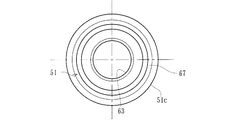
- the wheel bearing device 50 is connected to a hub wheel 51 for mounting a wheel (not shown) at one end, a double row rolling bearing 52 for rotatably supporting the hub wheel 51, and the hub wheel 51.
- a fixed type constant velocity universal joint 53 that transmits power of a drive shaft (not shown) to the hub wheel 51 is provided.
- the hub wheel 51 integrally has a wheel mounting flange 54 for mounting a wheel at one end, an inner rolling surface 51a on the outer periphery, and a cylindrical small-diameter step portion 51b extending in the axial direction from the inner rolling surface 51a. Is formed.
- the double-row rolling bearing 52 has a vehicle body mounting flange 55b integrally fixed to a suspension device (not shown) on the outer periphery, and an outer side in which double-row outer rolling surfaces 55a and 55a are formed on the inner periphery. It comprises a member 55 and an inner member 57 inserted into the outer member 55 via double rows of balls 56.
- the inner member 57 includes a hub wheel 51 and a separate inner ring 58 that is press-fitted into the small-diameter step portion 51b of the hub wheel 51 and has an inner rolling surface 58a formed on the outer periphery.
- the inner ring 58 is fixed to the hub wheel 51 in the axial direction by a caulking portion 51 c formed by plastically deforming the end portion of the small-diameter stepped portion 51 b of the hub wheel 51 radially outward.
- the constant velocity universal joint 53 includes an outer joint member 62 integrally including a cup-shaped mouth portion 59, a shoulder portion 60 that forms the bottom of the mouth portion 59, and a shaft portion 61 that extends from the shoulder portion 60 in the axial direction.
- the outer joint member 62 is fitted into the hub wheel 51 so as to be able to transmit torque. That is, the female serration 63 is formed on the inner periphery of the hub wheel 51, and the male serration 64 is formed on the outer periphery of the shaft portion 61 of the outer joint member 62, and both the serrations 63 and 64 are engaged with each other.
- the shaft portion 61 of the outer joint member 62 is fitted into the hub wheel 51 until the shoulder portion 60 is abutted against the caulking portion 51 c of the hub wheel 51, and the male screw 65 formed at the end of the shaft portion 61.
- the fixing nut 66 is fastened with a predetermined tightening torque, and the hub wheel 51 and the outer joint member 62 are detachably coupled in the axial direction.
- a portion that contacts the shoulder portion 60 of the outer joint member 62, that is, a caulking portion 51c of the hub wheel 51 is formed on a flat surface, as shown in FIG.
- the concave groove 67 is formed in the central portion in the radial direction of the flat surface of the caulking portion 51c.
- grease is filled in the concave groove 67.
- the present invention has been made in view of the above circumstances, and is a wheel bearing that alleviates a sudden slip that occurs between a caulking portion and a shoulder portion of an outer joint member, and prevents the occurrence of stick-slip noise.
- the object is to provide a device.
- the invention according to claim 1 of the present invention includes an outer member in which a double row outer rolling surface is integrally formed on the inner periphery, and a wheel for attaching a wheel to one end.
- a hub ring integrally having a mounting flange and having a cylindrical small-diameter step portion extending in the axial direction on the outer periphery, and at least one inner ring press-fitted into the small-diameter step portion of the hub ring,
- a movable body and a constant velocity universal joint connected to the hub ring, and the inner ring is connected to the hub ring by a caulking portion formed by plastically deforming an end of the small diameter step portion radially outward.
- the outer joint member of the constant velocity universal joint is fixed in the axial direction, and a cup-shaped mouth portion and this A shoulder portion that forms the bottom of the usb portion, and a stem portion that extends in the axial direction from the shoulder portion and is internally fitted to the hub wheel so as to be able to transmit torque via serrations, are integrally formed with the shoulder portion.
- a cap made of a low friction member is interposed between the crimping portion and the shoulder portion.
- the cap includes a disk-shaped contact portion, a cylindrical portion extending in an axial direction from an outer diameter portion of the contact portion, and a locking portion protruding radially inward from an end portion of the cylindrical portion.
- an inner diameter of the locking portion is set to be slightly smaller than an outer diameter of the crimping portion, and the cap is attached to the crimping portion by elastically deforming the locking portion.
- the caulking part and the shoulder A cap made of a low-friction member is interposed between the cylindrical portion, and the cap includes a disk-shaped contact portion, a cylindrical portion extending in an axial direction from the outer diameter portion of the contact portion, and the cylindrical portion A locking portion protruding radially inward from the end portion, the inner diameter of the locking portion is set to be slightly smaller than the outer diameter of the caulking portion, and the locking portion is elastically deformed.
- the cap Since the cap is attached to the caulking portion, when a large torque is applied to the drive shaft and a large twist occurs in the outer joint member, the cap is either one of the caulking portion and the shoulder portion of the outer joint member. To be accompanied by a moment later This reduces the friction coefficient of the abutment surface and suppresses the wear of the cap itself and the caulking part, and also reduces the sudden slip that occurs between the caulking part and the shoulder part with this cap. Generation of slip noise can be prevented.
- the cap is formed by pressing from a steel plate and a low friction film is formed on the surface by the permeation diffusion plating of molybdenum disulfide, as in the invention described in claim 2, the adhesion is improved. It is effective for this kind of application, which has good durability and abrupt slip on the contact surface.
- the ground treatment is performed by spraying grid-like silicon carbide on the surface of the cap, the adhesion of the low friction film can be improved.
- the cap may be formed by injection molding from a synthetic resin material to which a fibrous reinforcing material is added.
- the slit extended in an axial direction may be formed in the outer-diameter part which extends over the latching
- the locking portion may be formed of a locking piece formed in the circumferential direction. Thereby, it can be easily elastically deformed without strictly restricting the dimension of the locking portion, and the assembling performance of the cap is improved.
- the wheel bearing device integrally has an outer member integrally formed with a double row outer rolling surface on the inner periphery, and a wheel mounting flange for mounting the wheel on one end, and on the outer periphery.
- a hub wheel formed with a cylindrical small-diameter step portion extending in the axial direction, and at least one inner ring press-fitted into the small-diameter step portion of the hub wheel.
- a constant velocity universal joint and the inner ring is axially fixed to the hub ring by a caulking portion formed by plastically deforming an end of the small diameter step portion radially outward.
- the outer joint member of the universal joint includes a cup-shaped mouth portion and a shoulder portion that forms the bottom of the mouth portion,
- the hub wheel is integrally provided with a stem portion that extends in an axial direction from the shoulder portion and is fitted into the hub wheel so as to transmit torque via serration, and the shoulder portion is in contact with the caulking portion.
- a cap made of a low friction member is interposed between the caulking portion and the shoulder portion.
- a contact portion a cylindrical portion extending in an axial direction from an outer diameter portion of the contact portion; and a locking portion protruding radially inward from an end portion of the cylindrical portion.
- An outer member integrally having a vehicle body mounting flange on the outer periphery, an outer member formed integrally with a double row outer rolling surface on the inner periphery, a wheel mounting flange integrally on one end, and the double row on the outer periphery.
- a hub ring formed with an inner rolling surface facing one of the outer rolling surfaces, a cylindrical small diameter step portion extending in an axial direction from the inner rolling surface, and a small diameter step portion of the hub ring,
- An inner member composed of an inner ring having an inner race surface formed with an inner race surface facing the other of the outer rows of the double rows on the outer periphery, and freely rollable between both raceway surfaces of the inner member and the outer member.
- a constant velocity universal joint connected to the hub wheel, and a crimping portion formed by plastically deforming an end portion of the small diameter step portion radially outward.
- An inner ring is fixed in an axial direction with respect to the hub ring, and an outer joint member of the constant velocity universal joint is a cup-shaped mouse. And a stem part extending in the axial direction from the shoulder part and fitted in the hub wheel so as to be able to transmit torque via serration.
- a cap formed by pressing from the steel plate is attached to the caulking portion
- the cap protrudes inward in the radial direction from the disk-shaped contact portion, the cylindrical portion extending in the axial direction from the outer diameter portion of the contact portion, and the end portion of the cylindrical portion.
- a locking portion having a diameter slightly smaller than the outer diameter of the tightening portion, and a low-friction film formed by permeation diffusion plating of molybdenum disulfide is formed on the surface of the cap.
- FIG. 1 is a longitudinal sectional view showing an embodiment of a wheel bearing device according to the present invention
- FIG. 2 is an enlarged view of a main part of FIG. 1
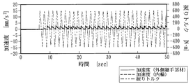
- FIG. 3 is a test of a sample equipped with a cap according to the present invention.
- FIG. 4 is a graph showing a waveform in a test of a sample as a comparative example
- FIG. 5A is a front view showing a modified example of the cap of FIG. 2, and FIG. FIG.
- the side closer to the outer side of the vehicle when assembled to the vehicle is referred to as the outer side (left side in FIG. 1), and the side closer to the center is referred to as the inner side (right side in FIG. 1).
- This wheel bearing device is referred to as a third generation for driving wheels, and is a double row rolling element (ball) accommodated in a freely rollable manner between the inner member 1, the outer member 10, and both members 1, 10.
- the constant velocity universal joint 13 is detachably coupled.
- the inner member 1 includes a hub ring 2 and an inner ring 3 press-fitted into the hub ring 2.
- the hub wheel 2 integrally has a wheel mounting flange 4 for attaching a wheel (not shown) to an end portion on the outer side, one (outer side) inner rolling surface 2a on the outer periphery, and this inner rolling.
- a cylindrical small diameter step portion 2b extending in the axial direction from the surface 2a is formed, and a serration (or spline) 2c for torque transmission is formed on the inner periphery.
- Hub bolts 5 for attaching the wheels are planted at circumferentially equidistant positions of the wheel mounting flanges 4.
- the hub wheel 2 is formed of medium and high carbon steel containing 0.40 to 0.80% by weight of carbon such as S53C, and includes a base portion serving as a seal land portion in which an outer rolling seal 11 to be described later comes into sliding contact with the inner rolling surface 2a. 7 to the small diameter step portion 2b, the surface hardness is set in the range of 58 to 64HRC by induction hardening. Then, the inner ring 3 with the other (inner side) inner rolling surface 3a formed on the outer periphery is press-fitted into the small-diameter step portion 2b of the hub wheel 2 via a predetermined shimiro, and the end portion of the small-diameter step portion 2b is radially inserted.
- the inner ring 3 is fixed in the axial direction by a caulking portion 6 formed by plastic deformation outward.
- the end surface of the crimping portion 6 is formed as a flat surface, so that the surface pressure applied to the crimping portion 6 by the axial force can be reduced, and plastic deformation and wear of the crimping portion 6 can be prevented.
- the inner ring 3 and the rolling element 8 are made of high carbon chrome steel such as SUJ2, and the other (inner side) inner rolling surface 3a is formed on the outer periphery, and is hardened in the range of 58 to 64 HRC to the core part by quenching. Has been processed.
- the outer member 10 integrally has a vehicle body mounting flange 10b for mounting to the vehicle body (not shown) on the outer periphery, and has a double row facing the inner rolling surfaces 2a and 3a of the inner member 1 on the inner periphery.
- Outer rolling surfaces 10a and 10a are integrally formed.
- the outer member 10 is made of medium and high carbon steel containing 0.40 to 0.80% by weight of carbon such as S53C, and the double row outer rolling surfaces 10a and 10a have a surface hardness in the range of 58 to 64HRC by induction hardening. Is cured.
- the double-row rolling elements 8 and 8 are accommodated so that rolling is possible via the holder
- Seals 11 and 12 are attached to the opening of the annular space formed between the outer member 10 and the inner member 1 to prevent leakage of the lubricating grease sealed inside the bearing and from the outside. It prevents rainwater and dust from entering the
- a double row angular contact ball bearing using a ball as the rolling element 8 is exemplified.
- the present invention is not limited to this.
- a double row tapered roller bearing using a tapered roller as the rolling element 8 is provided.
- a so-called third generation structure in which one inner rolling surface 2a is directly formed on the outer periphery of the hub wheel 2 is illustrated, but although not illustrated, a pair of inner rings are provided on the small-diameter step portion of the hub wheel. It may be a so-called first or second generation structure that is press-fitted.
- the constant velocity universal joint 13 includes an outer joint member 14, a joint inner ring, a cage and a torque transmission ball (not shown).
- the outer joint member 14 is made of medium-high carbon steel containing 0.40 to 0.80% by weight of carbon such as S53C, and has a cup-shaped mouth portion (not shown) and a shoulder portion 15 that forms the bottom of the mouth portion.
- the stem portion 16 extending in the axial direction from the shoulder portion 15 is integrally provided.
- the stem portion 16 has a serration (or spline) 16a engaged with the serration 2c of the hub wheel 2 on the outer periphery, and a male screw 16b formed at the end of the serration 16a.
- the stem portion 16 of the outer joint member 14 is fitted and inserted into the hub wheel 2 until the shoulder portion 15 abuts against the caulking portion 6 via a cap 17 which will be described later, and the caulking portion 6 and the shoulder portion 15 face each other.
- the fixing nut 18 is fastened to the male screw 16b with a predetermined tightening torque, and the hub wheel 2 and the outer joint member 14 are detachably coupled in the axial direction.
- a cap 17 is attached to the caulking portion 6.
- the cap 17 has a cross-section by pressing a corrosion-resistant steel plate such as a cold-rolled steel plate (JIS standard SPCC type) or austenitic stainless steel plate (JIS standard SUS304 type) that has been rust-proofed.
- a corrosion-resistant steel plate such as a cold-rolled steel plate (JIS standard SPCC type) or austenitic stainless steel plate (JIS standard SUS304 type) that has been rust-proofed.
- JIS standard SPCC type cold-rolled steel plate
- austenitic stainless steel plate JIS standard SUS304 type
- the inner diameter of the locking portion 17c is set to be slightly smaller than the outer diameter of the crimping portion 6, and the cap 17 is attached to the crimping portion 6 by elastically deforming the locking portion 17c.
- the cap 17 faces the large end surface 3b of the inner ring 3 through an axial clearance of 1 mm at the maximum, and has a labyrinth structure.
- the cap 17 can be attached to the caulking portion 6 with one touch, and the cap 17 can be prevented from falling off from the caulking portion 6 in the assembling process, and the labyrinth structure allows the cap 17 to move to the caulking portion 6. Intrusion of foreign matter such as rainwater and dust can be prevented, and rusting of the crimped portion 6 can be prevented to improve durability.
- the elastic deformation can be performed without strictly restricting the size of the locking portion 17c.
- the cap 17 can be easily assembled.
- a low friction film 19 having a film thickness of 0.3 to 1.0 mm is formed on the surface of the cap 17.
- the low friction film 19 is formed by a so-called PIP process (penetration diffusion plating process) in which a powder made of molybdenum disulfide is shot peened on the surface of the cap 17 to diffuse and infiltrate the element.
- this treatment was performed by applying molybdenum disulfide having a particle size of about 5 ⁇ m in a scaly particle shape at an injection pressure of 0.5 MPa for about 20 sec. This is done by shot peening.
- ground treatment by spraying grid-like SiC (silicon carbide) having a particle size number of 400 (40 to 50 ⁇ m) onto the surface of the cap 17.
- the cap 17 on which such a low friction film 19 is formed is attached to the caulking portion 6, and the caulking portion 6 and the shoulder portion 15 are in contact with each other through the cap 17, and the hub wheel 2 and the outer joint member 14 are in the axial direction. Since a large torque is applied to the drive shaft (not shown) and a large twist occurs in the outer joint member 14, the cap 17 is attached to the shoulders of the caulking portion 6 and the outer joint member 14. The unit 15 will be accompanied by a momentary delay. Accordingly, the friction coefficient of the abutting surface is reduced to suppress the wear of the cap 17 itself and the wear of the caulking portion 6, and a sudden slip generated between the caulking portion 6 and the shoulder portion 15 is caused by the cap 17. And can prevent the occurrence of stick-slip noise.
- FIG. 3 and 4 show the results of the abnormal noise generation test conducted by the applicant.
- FIG. 3 shows a waveform graph of a sample with a low friction coating 19 according to the present invention, that is, a sample with a cap 17 whose surface is subjected to PIP treatment of molybdenum disulfide
- FIG. 4 is a sample with other caps attached.
- the waveform graph of (typical example) is shown.
- the test conditions are a set axial force of 50 kN, an input torque of ⁇ 0.6 kN ⁇ m, a frequency of 0.8 Hz, and an operation frequency of 36,000 times.
- the criterion was determined as pass / fail based on the presence or absence of abnormal noise of 77 db or more after the initial and endurance tests.
- Table 1 shows the test results of each sample performed.
- the accelerations of the outer joint member 14 and the inner ring 3 are substantially the same, the acceleration of the inner ring 3 is not greatly changed, and abnormal noise is generated. There wasn't.
- the acceleration of the outer joint member 14 and the inner ring 3 is different, and the acceleration of the inner ring 3 varies greatly everywhere, and abnormal noise is observed. It was.
- the low friction film 19 obtained by PIP treatment of MoS 2 has better adhesion and durability than Sn shot products, and as can be seen from Table 1, this kind of abrupt slip occurs on the contact surface. It is considered effective for use.
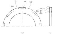
- FIG. 5 is a modified example of the cap described above, (a) is a front view, and (b) is a cross-sectional view.
- the cap 20 is formed by injection molding from a synthetic resin material made of PA (polyamide) 66 to which 30 wt% of a fiber reinforcing material of GF (glass fiber) is added.
- a cylindrical portion 20b extending in the axial direction from the outer diameter portion of the contact portion 20a, and a locking portion 20c protruding inward in the radial direction are provided at the end of the cylindrical portion 20b.
- the locking portion 20c is composed of a plurality of locking pieces formed in the circumferential direction.
- the inner diameter of the locking portion 20c is set to be slightly smaller than the outer diameter of the crimping portion 6, and the cap 20 is attached to the crimping portion 6 by elastically deforming the locking portion 20c.
- the wear resistance is improved, the elastic deformation is facilitated and the assemblability is remarkably improved, and the caulking portion 6 and the shoulder portion 15 of the outer joint member 14 are in contact with each other as in the cap 17 described above. Since the cap 20 slightly moves with a twist of one of the members, the wear of the caulking portion 6 is suppressed, and a sudden slip generated between the caulking portion 6 and the shoulder portion 15 occurs. Can be mitigated and the occurrence of stick-slip noise can be prevented.
- the cap 20 is made of PPA (polyphthalamide), PBT (polybutylene terephthalate), polyphenylene sulfide (PPS), polyetheretherketone (PEEK), thermoplastic polyimide (PI), polyamideimide (PAI) in addition to the materials described above. ) And the like can be illustrated as an injection-moldable synthetic resin.
- PPA polyphthalamide
- PBT polybutylene terephthalate
- PPS polyphenylene sulfide
- PEEK polyetheretherketone
- PI polyetheretherketone
- PAI polyamideimide
- a wheel bearing device includes an inner member composed of a hub wheel and an inner ring, and a constant velocity universal joint, and the inner member and the outer joint member of the constant velocity universal joint are detachably fastened in a butted state. Further, the present invention can be applied to wheel bearing devices having first to third generation structures.
- FIG. 7 is an arrow view along the line VII-VII in FIG. 6.
- Car body mounting flange 56 ... ⁇ ⁇ ⁇ ⁇ ⁇ ⁇ ⁇ ⁇ ⁇ Ball 57 ⁇ ⁇ ⁇ ⁇ ⁇ ⁇ ⁇ ⁇ ⁇ ⁇ ⁇ Inner member 58 ⁇ ⁇ ⁇ ⁇ ⁇ ⁇ ⁇ ⁇ ⁇ ⁇ Inner ring 59 ⁇ ⁇ ⁇ ⁇ ⁇ ⁇ ⁇ ⁇ ⁇ ... Mouse part 60 ......... Shoulder part 60a ......... Contact surface 61 ... Portion 62 ... Outer joint member 63 ... Female serration 64 ...
Landscapes
- Engineering & Computer Science (AREA)
- Mechanical Engineering (AREA)
- General Engineering & Computer Science (AREA)
- Rolling Contact Bearings (AREA)
- Mounting Of Bearings Or Others (AREA)
Abstract
L'invention porte sur un palier de roue pouvant réduire le glissement brusque qui se produit entre la partie matée et la partie épaulement de l'élément de joint externe et qui peut empêcher la génération de bruit de broutage. Dans un dispositif de palier de roue dans lequel un élément de joint externe (14) est couplé, d'une manière librement détachable dans la direction axiale et d'une manière permettant le transfert de couple par l'intermédiaire de dentelures, à une bague de moyeu (2) sur laquelle une bague interne (3) est fixée par une partie matée (6), un capuchon (17), formé par pressage à partir d'une tôle d'acier, est monté sur la partie matée (6). Ledit capuchon (17) est équipé d'une partie contact en forme de disque (17a), d'une partie cylindrique (17b) qui s'étend dans la direction axiale à partir de la partie diamètre externe de ladite partie contact (17a), et d'une partie fixation (17c) qui se projette vers l'intérieur dans la direction radiale à partir de la partie extrémité de ladite partie cylindrique (17b) et dont le diamètre interne est légèrement plus petit que le diamètre externe de la partie matée (6). Un film à faible friction (19) est également formé par placage à diffusion pénétrante de disulfure de molybdène sur la surface dudit capuchon (17).
Priority Applications (2)
| Application Number | Priority Date | Filing Date | Title |
|---|---|---|---|
| CN2009801082595A CN102015326B (zh) | 2008-03-10 | 2009-02-24 | 车轮用轴承装置 |
| US12/879,344 US8313245B2 (en) | 2008-03-10 | 2010-09-10 | Wheel bearing apparatus for a vehicle |
Applications Claiming Priority (2)
| Application Number | Priority Date | Filing Date | Title |
|---|---|---|---|
| JP2008-059720 | 2008-03-10 | ||
| JP2008059720A JP5595641B2 (ja) | 2008-03-10 | 2008-03-10 | 車輪用軸受装置 |
Related Child Applications (1)
| Application Number | Title | Priority Date | Filing Date |
|---|---|---|---|
| US12/879,344 Continuation US8313245B2 (en) | 2008-03-10 | 2010-09-10 | Wheel bearing apparatus for a vehicle |
Publications (1)
| Publication Number | Publication Date |
|---|---|
| WO2009113252A1 true WO2009113252A1 (fr) | 2009-09-17 |
Family
ID=41064925
Family Applications (1)
| Application Number | Title | Priority Date | Filing Date |
|---|---|---|---|
| PCT/JP2009/000792 WO2009113252A1 (fr) | 2008-03-10 | 2009-02-24 | Dispositif de palier de roue |
Country Status (4)
| Country | Link |
|---|---|
| US (1) | US8313245B2 (fr) |
| JP (1) | JP5595641B2 (fr) |
| CN (1) | CN102015326B (fr) |
| WO (1) | WO2009113252A1 (fr) |
Cited By (1)
| Publication number | Priority date | Publication date | Assignee | Title |
|---|---|---|---|---|
| US8944196B2 (en) | 2010-03-30 | 2015-02-03 | Ntn Corporation | Wheel bearing apparatus incorporated with an in-wheel motor |
Families Citing this family (4)
| Publication number | Priority date | Publication date | Assignee | Title |
|---|---|---|---|---|
| JP2012001010A (ja) * | 2010-06-14 | 2012-01-05 | Ntn Corp | 車輪用軸受装置 |
| ITTO20130507A1 (it) * | 2013-06-19 | 2014-12-20 | Skf Ab | Dispositivo flessibile di tenuta per gruppi mozzi ruota connessi a giunti omocinetici |
| JP6449689B2 (ja) * | 2015-03-11 | 2019-01-09 | Ntn株式会社 | 車輪用軸受装置 |
| CN114033810A (zh) * | 2021-11-11 | 2022-02-11 | 上海纳铁福传动系统有限公司 | 一种等速万向节传动轴与轮毂轴承单元的扭矩传递结构 |
Citations (6)
| Publication number | Priority date | Publication date | Assignee | Title |
|---|---|---|---|---|
| JP2005145315A (ja) * | 2003-11-18 | 2005-06-09 | Ntn Corp | 駆動車輪用軸受装置 |
| JP2006188187A (ja) * | 2005-01-07 | 2006-07-20 | Ntn Corp | 車輪用軸受装置 |
| JP2006275174A (ja) * | 2005-03-29 | 2006-10-12 | Ntn Corp | 駆動車輪用軸受装置 |
| JP2007276764A (ja) * | 2006-03-13 | 2007-10-25 | Ntn Corp | 駆動車輪用軸受装置 |
| JP2007292203A (ja) * | 2006-04-25 | 2007-11-08 | Ntn Corp | 駆動車輪用軸受装置 |
| JP2007298092A (ja) * | 2006-04-28 | 2007-11-15 | Ntn Corp | 駆動車輪用軸受装置 |
Family Cites Families (10)
| Publication number | Priority date | Publication date | Assignee | Title |
|---|---|---|---|---|
| US3300258A (en) * | 1964-03-05 | 1967-01-24 | Teleflex Inc | Bearing and method for making same |
| JPS5285617A (en) * | 1976-01-12 | 1977-07-16 | Riken Corp | Sliding member surface layer |
| JPH0718906U (ja) * | 1993-09-17 | 1995-04-04 | 光洋精工株式会社 | 車輪用軸受装置 |
| JPH07317753A (ja) * | 1994-05-31 | 1995-12-08 | Ntn Corp | 車輪用軸受ユニット |
| ITTO20010849A1 (it) * | 2001-09-06 | 2003-03-06 | Skf Ind Spa | Dispositivo di tenuta per cuscinetti. |
| JP2003136908A (ja) | 2001-10-30 | 2003-05-14 | Nsk Ltd | 車輪駆動用軸受ユニット |
| DE50306919D1 (de) * | 2003-10-24 | 2007-05-10 | Gkn Driveline Int Gmbh | Gelenkaussenteil mit Abstützscheibe |
| JP2005147298A (ja) * | 2003-11-18 | 2005-06-09 | Ntn Corp | 車輪用軸受装置 |
| JP2005324714A (ja) * | 2004-05-17 | 2005-11-24 | Ntn Corp | 車輪用軸受装置 |
| JP5184820B2 (ja) * | 2007-06-01 | 2013-04-17 | Ntn株式会社 | 車輪用軸受装置 |
-
2008
- 2008-03-10 JP JP2008059720A patent/JP5595641B2/ja active Active
-
2009
- 2009-02-24 CN CN2009801082595A patent/CN102015326B/zh not_active Expired - Fee Related
- 2009-02-24 WO PCT/JP2009/000792 patent/WO2009113252A1/fr active Application Filing
-
2010
- 2010-09-10 US US12/879,344 patent/US8313245B2/en not_active Expired - Fee Related
Patent Citations (6)
| Publication number | Priority date | Publication date | Assignee | Title |
|---|---|---|---|---|
| JP2005145315A (ja) * | 2003-11-18 | 2005-06-09 | Ntn Corp | 駆動車輪用軸受装置 |
| JP2006188187A (ja) * | 2005-01-07 | 2006-07-20 | Ntn Corp | 車輪用軸受装置 |
| JP2006275174A (ja) * | 2005-03-29 | 2006-10-12 | Ntn Corp | 駆動車輪用軸受装置 |
| JP2007276764A (ja) * | 2006-03-13 | 2007-10-25 | Ntn Corp | 駆動車輪用軸受装置 |
| JP2007292203A (ja) * | 2006-04-25 | 2007-11-08 | Ntn Corp | 駆動車輪用軸受装置 |
| JP2007298092A (ja) * | 2006-04-28 | 2007-11-15 | Ntn Corp | 駆動車輪用軸受装置 |
Cited By (1)
| Publication number | Priority date | Publication date | Assignee | Title |
|---|---|---|---|---|
| US8944196B2 (en) | 2010-03-30 | 2015-02-03 | Ntn Corporation | Wheel bearing apparatus incorporated with an in-wheel motor |
Also Published As
| Publication number | Publication date |
|---|---|
| US8313245B2 (en) | 2012-11-20 |
| JP5595641B2 (ja) | 2014-09-24 |
| JP2009214676A (ja) | 2009-09-24 |
| CN102015326A (zh) | 2011-04-13 |
| US20100329598A1 (en) | 2010-12-30 |
| CN102015326B (zh) | 2013-01-02 |
Similar Documents
| Publication | Publication Date | Title |
|---|---|---|
| JP5184820B2 (ja) | 車輪用軸受装置 | |
| JP4557223B2 (ja) | 駆動車輪用軸受装置 | |
| JP4526998B2 (ja) | 駆動車輪用軸受装置 | |
| JP5134356B2 (ja) | 車輪用軸受装置 | |
| WO2009113252A1 (fr) | Dispositif de palier de roue | |
| JP6629545B2 (ja) | 車輪用軸受装置 | |
| WO2014109331A1 (fr) | Dispositif de palier pour roue | |
| JP6309228B2 (ja) | 車輪用軸受装置の製造方法 | |
| JP2009287699A (ja) | 車輪用軸受装置 | |
| JP4868891B2 (ja) | 車輪用軸受装置 | |
| WO2007122809A1 (fr) | Dispositif de palier pour roue | |
| JP6534458B2 (ja) | 密封装置およびこれを備えた車輪用軸受装置 | |
| JP5415773B2 (ja) | 車輪用軸受装置 | |
| JP2008163979A (ja) | 車輪用軸受装置 | |
| JP2004084763A (ja) | 駆動車輪用軸受 | |
| JP6661308B2 (ja) | 車輪用軸受装置 | |
| JP2009257375A (ja) | 車輪用軸受装置 | |
| JP2006297963A (ja) | 駆動車輪用軸受装置 | |
| JP2013166487A (ja) | 車輪用軸受装置 | |
| JP2013040664A (ja) | 車輪用軸受装置 | |
| JP4371428B2 (ja) | 車輪用軸受およびそれを備えた車輪用軸受装置 | |
| JP2009286310A (ja) | 駆動車輪用軸受装置 | |
| JP2011005956A (ja) | 車輪用軸受装置 | |
| JP2010023604A (ja) | 車輪用軸受装置 | |
| JP2010042763A (ja) | 車輪用軸受装置 |
Legal Events
| Date | Code | Title | Description |
|---|---|---|---|
| WWE | Wipo information: entry into national phase |
Ref document number: 200980108259.5 Country of ref document: CN |
|
| 121 | Ep: the epo has been informed by wipo that ep was designated in this application |
Ref document number: 09720420 Country of ref document: EP Kind code of ref document: A1 |
|
| NENP | Non-entry into the national phase |
Ref country code: DE |
|
| 122 | Ep: pct application non-entry in european phase |
Ref document number: 09720420 Country of ref document: EP Kind code of ref document: A1 |