WO2009107388A1 - レール装置とこれを用いた冷蔵庫 - Google Patents
レール装置とこれを用いた冷蔵庫 Download PDFInfo
- Publication number
- WO2009107388A1 WO2009107388A1 PCT/JP2009/000873 JP2009000873W WO2009107388A1 WO 2009107388 A1 WO2009107388 A1 WO 2009107388A1 JP 2009000873 W JP2009000873 W JP 2009000873W WO 2009107388 A1 WO2009107388 A1 WO 2009107388A1
- Authority
- WO
- WIPO (PCT)
- Prior art keywords
- rail
- refrigerator
- flange
- refrigerator according
- inner box
- Prior art date
Links
Images


Classifications
-
- A—HUMAN NECESSITIES
- A47—FURNITURE; DOMESTIC ARTICLES OR APPLIANCES; COFFEE MILLS; SPICE MILLS; SUCTION CLEANERS IN GENERAL
- A47B—TABLES; DESKS; OFFICE FURNITURE; CABINETS; DRAWERS; GENERAL DETAILS OF FURNITURE
- A47B88/00—Drawers for tables, cabinets or like furniture; Guides for drawers
- A47B88/40—Sliding drawers; Slides or guides therefor
- A47B88/49—Sliding drawers; Slides or guides therefor with double extensible guides or parts
- A47B88/493—Sliding drawers; Slides or guides therefor with double extensible guides or parts with rollers, ball bearings, wheels, or the like
-
- F—MECHANICAL ENGINEERING; LIGHTING; HEATING; WEAPONS; BLASTING
- F25—REFRIGERATION OR COOLING; COMBINED HEATING AND REFRIGERATION SYSTEMS; HEAT PUMP SYSTEMS; MANUFACTURE OR STORAGE OF ICE; LIQUEFACTION SOLIDIFICATION OF GASES
- F25D—REFRIGERATORS; COLD ROOMS; ICE-BOXES; COOLING OR FREEZING APPARATUS NOT OTHERWISE PROVIDED FOR
- F25D25/00—Charging, supporting, and discharging the articles to be cooled
- F25D25/02—Charging, supporting, and discharging the articles to be cooled by shelves
- F25D25/024—Slidable shelves
- F25D25/025—Drawers
-
- A—HUMAN NECESSITIES
- A47—FURNITURE; DOMESTIC ARTICLES OR APPLIANCES; COFFEE MILLS; SPICE MILLS; SUCTION CLEANERS IN GENERAL
- A47B—TABLES; DESKS; OFFICE FURNITURE; CABINETS; DRAWERS; GENERAL DETAILS OF FURNITURE
- A47B2210/00—General construction of drawers, guides and guide devices
- A47B2210/17—Drawers used in connection with household appliances
-
- F—MECHANICAL ENGINEERING; LIGHTING; HEATING; WEAPONS; BLASTING
- F25—REFRIGERATION OR COOLING; COMBINED HEATING AND REFRIGERATION SYSTEMS; HEAT PUMP SYSTEMS; MANUFACTURE OR STORAGE OF ICE; LIQUEFACTION SOLIDIFICATION OF GASES
- F25D—REFRIGERATORS; COLD ROOMS; ICE-BOXES; COOLING OR FREEZING APPARATUS NOT OTHERWISE PROVIDED FOR
- F25D23/00—General constructional features
- F25D23/02—Doors; Covers
- F25D23/021—Sliding doors
Definitions
- the present invention relates to a refrigerator, and more particularly to a drawer structure of a storage room.
- a refrigerator has a plurality of storage rooms such as a refrigerator compartment, a freezer compartment, and a vegetable compartment.
- the freezer compartment and the vegetable compartment are generally provided as drawer-type storage rooms in the lower stage of the refrigerator from the viewpoint of cooling efficiency and convenience.
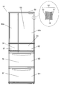
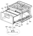
- FIG. 40 is a side sectional view of a conventional refrigerator.
- a conventional refrigerator 4051 shown in FIG. 40 has an ice box (not shown) provided in the heat-insulating box 4019, the refrigerator compartment 4025 from the top, the switching chamber 4026 capable of changing the temperature below the refrigerator compartment 4025, and the switching chamber 4026. 1), a vegetable room 4027 is provided below the switching room 4026 and the ice making room, and a freezing room 4028 is provided below the vegetable room 4027 as a storage room.
- the heat insulation box 4019 is formed of an outer box 4021 and an inner box 4020, and a foam heat insulating material 4022 filled between the outer box 4021 and the inner box 4020.
- the container 4027a forming the vegetable compartment 4027 is supported by two rail members 4031 connected to the vegetable compartment drawer door 4029.
- the container 4028a forming the freezer compartment 4028 is supported by two rail members 4031 connected to the freezer compartment drawer door 4030.
- the vegetable compartment 4027 and the freezer compartment 4028 are configured as described above, so that they are drawer-type storage rooms that can be taken in and out of the heat insulating box 4019.
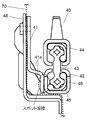
- FIG. 41 is an exploded view of the rail member 4031 in the conventional refrigerator 4051.
- FIG. 42 is a front view showing an outline of the configuration of the rail member 4031 in the conventional refrigerator 4051.
- the conventional rail member 4031 shown in FIGS. 41 and 42 includes a first rail (fixed rail) 4031a, a third rail (moving rail) 4031b, a first rail (fixed rail) 4031a, and a third rail (moving rail).
- the second rail (intermediate traveling rail) 4031c provided between 4031b, the second rail (intermediate traveling rail) 4031c, the first rail (fixed rail) 4031a, and the third rail (moving rail) 4031b are engaged. It comprises a plurality of bearings 4031d to support.
- the plurality of bearings 4031d are rotatably held by a ball gauge 4031e.
- the rail member 4031 in a state in which these components are combined is attached to the heat insulating box 4019 by fixing the first rail (fixed rail) 4031a to the inner side surface of the inner box 4020.
- one rail member 4031 is attached to the inner side surface of the inner box 4020 at positions corresponding to the left and right sides of the vegetable room 4027 and the freezing room 4028, respectively. That is, if the left and right are one set, two sets of first rails (fixed rails) 4031a are attached to the inner side surface of the inner box 4020.
- each 1st rail (fixed rail) 4031a is attached to the inner surface of the inner box 4020 by fastening with the holder rail 4032 and the bolt across the inner box 4020 as shown in FIG.
- a vegetable room drawer door 4029 is attached to the tip of two third rails (moving rails) 4031b of one set located above, and frozen at the tip of the two third rails (moving rails) 4031b of the other set.
- a room drawer door 4030 is attached.
- the container 4027a of the vegetable compartment 4027 is supported on the left and right by two third rails (moving rails) 4031b, and is synchronized with the movement of the vegetable compartment drawer door 4029 in the front-rear direction together with the third rail (moving rail) 4031b. Move back and forth.
- the container 4027a can be easily attached and detached upward.
- the container 4028a can be easily attached and detached upward.
- the rail member 4031 adopts the structure as described above, so that the so-called rattling is reduced and the container can be easily attached and detached.
- pull-out storage rooms such as vegetable rooms in refrigerators tend to increase the capacity that can be accommodated by deciding the arrangement of components in the refrigerator in response to consumer needs.
- a conventional rail member 4031 is used as a drawer mechanism for a storage chamber having a larger capacity.
- the rail member 4031 is heavier to support and has a longer pull-out distance.
- the portion surrounded by the dotted line of the first rail (fixed rail) 4031a is in the direction of the arrow. Easier to fall down (inside the cabinet). In other words, the first rail (fixed rail) 4031a is placed in an environment that is easier to open.
- the deformation problem can be solved by increasing the thickness of the first rail (fixed rail) 4031a or the like, or by using a special material having high rigidity.
- the innermost part (the storage chamber side end face) of the third rail (moving rail) is often located outside the forefront part of the outer box. It is desirable to protect the exposed part of the innermost part (end surface on the storage room side) of the rail (moving rail).
- the present invention provides a refrigerator that includes a drawer-type storage room and that does not lose its usability even if the storage room has a large capacity.
- the refrigerator of the present invention is a refrigerator including an inner box, an outer box, a heat insulating box formed by a heat insulating material filled between the inner box and the outer box, and a drawer-type storage chamber.
- the storage chamber has a long first rail (first rail (fixed rail)), second rail (intermediate rail) and third rail (third rail (moving rail)).
- a rail device is provided that supports the storage container so as to be movable back and forth.
- the said rail apparatus is provided with the fall prevention part of the said rail apparatus, and supports the said storage container directly or indirectly to the said 3rd rail, and can slide back and forth.
- the present invention is a refrigerator provided with a rail protection component on the end face of the third rail on the storage room side.
- the rail device includes a rail device falling prevention portion, and therefore, it is difficult to open when a force is applied to the rail device. Moreover, even if the rail apparatus in the refrigerator of this invention supports the large-capacity storage room so that it can be fully opened, the deformation
- the rail protection component even when the large-capacity storage room is supported so as to be fully opened, the end face of the third rail on the storage room side can be protected. Safety and appearance are preserved.
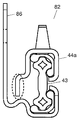
- FIG. 1 is a front view of the refrigerator according to Embodiment 1 of the present invention.
- FIG. 2 is a perspective view showing a state in which the vegetable compartment of the refrigerator in Embodiment 1 of the present invention is pulled out.
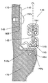
- FIG. 3 is a front view showing a schematic configuration of the rail device according to the first embodiment.
- FIG. 4 is a first perspective view showing the appearance of the rail device according to the first embodiment.
- FIG. 5 is a second perspective view showing the appearance of the rail device according to the first embodiment.
- FIG. 6 is a cross-sectional view seen from the side of the refrigerator in Embodiment 1 of the present invention.
- FIG. 7 is a cross-sectional view seen from the front of the refrigerator in the first embodiment of the present invention.
- FIG. 8 is an exploded view of the refrigerator according to Embodiment 1 of the present invention.
- FIG. 9 is an exploded view of the rail device according to the first embodiment of the present invention.
- FIG. 10 is a front view showing a schematic configuration of the rail device according to the first embodiment of the present invention.
- FIG. 11 is a front view showing a schematic configuration of the rail device according to the second embodiment of the present invention.
- FIG. 12 is a front view showing a schematic configuration of the rail device 81 according to the third embodiment of the present invention.
- FIG. 13: is a front view which shows the structure outline
- FIG. 14 is a front view showing a configuration outline of the rail device according to the fifth embodiment of the present invention.
- FIG. 14 is a front view showing a configuration outline of the rail device according to the fifth embodiment of the present invention.
- FIG. 15 is a front view of a refrigerator according to Embodiment 6 of the present invention.
- FIG. 16 is a perspective view which shows the state which pulled out the vegetable compartment of the refrigerator in Embodiment 6 of this invention.
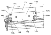
- FIG. 17 is a cross-sectional view showing a schematic configuration of rail device 140 according to Embodiment 6 of the present invention.
- FIG. 18 is a perspective view showing the appearance of the rail device in the sixth embodiment of the present invention.
- FIG. 19 is a perspective view showing the attachment state of the holder rail in the sixth embodiment of the present invention.
- FIG. 20 is a perspective view showing a holder rail in the sixth embodiment of the present invention.
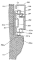
- FIG. 21 is a sectional view showing a schematic configuration of another rail device according to the sixth embodiment of the present invention.
- FIG. 22 is a sectional view showing a schematic configuration of the rail device according to the seventh embodiment of the present invention.
- FIG. 23 is a cross-sectional view showing a schematic configuration of another rail device according to the seventh embodiment of the present invention.
- FIG. 24 is a front view of the refrigerator according to the eighth embodiment of the present invention.
- FIG. 25 is a longitudinal sectional view of the refrigerator according to the eighth embodiment.
- FIG. 26 is an enlarged perspective view showing the appearance of the storage case in the eighth embodiment.
- FIG. 27 is a plan sectional view showing the storage case 521 and the drawer unit 540 according to the eighth embodiment.
- FIG. 28 is a front view of the refrigerator according to the ninth embodiment of the present invention.
- FIG. 29 is a front view of the refrigerator in the tenth embodiment of the present invention.
- FIG. 30 is a perspective view showing a state in which the vegetable room of the refrigerator in the tenth embodiment of the present invention is pulled out.
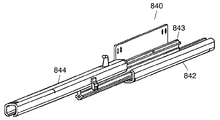
- FIG. 31 is a perspective view showing the appearance of the rail device for the refrigerator in the tenth embodiment of the present invention.
- FIG. 32 is a side view showing a state in which the vegetable compartment of the refrigerator in the tenth embodiment of the present invention is pulled out.
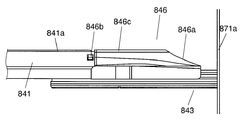
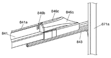
- FIG. 33 is a side view of a main part of the rail device for the refrigerator according to the tenth embodiment of the present invention.
- FIG. 34 is a perspective view of relevant parts of the rail device for the refrigerator according to the tenth embodiment of the present invention.
- FIG. 35 is a cross-sectional view showing an attachment state of the rail protection component and the door frame of the rail device for the refrigerator in the tenth embodiment of the present invention.
- FIG. 36 is a perspective view of the rail protection component of the rail device for the refrigerator according to the tenth embodiment of the present invention as seen from the back.
- FIG. 37 is a sectional view showing an outline of a rail device for a refrigerator in an eleventh embodiment of the present invention.
- FIG. 38 is a sectional view showing an outline of another rail device of the refrigerator in the eleventh embodiment of the present invention.
- FIG. 39 is a perspective view showing a rail device mounting method according to Embodiment 12 of the present invention.
- FIG. 40 is a side sectional view of a conventional refrigerator.
- FIG. 41 is an exploded view of a rail member 4031 in a conventional refrigerator 4051.
- FIG. 42 is a front view showing a configuration outline of rail member 4031 in conventional refrigerator 4051.
- Rail protection component 41, 84, 541 Bracket (fixing member) 41a, 900, 902, 905 rib (reinforcement part) 42, 86, 142, 201, 211 First rail 43, 43a, 85, 143, 203, 213 Second rail 43b Upper flange 43c Base plate 43d Lower flange 44, 44a, 144, 202, 212 Third rail 45, 145 204,631d Bearing (sliding member) 46,146 Ball gauge 48,148,205,215 Holder rail (auxiliary member) 51,151,500,618,700,851 Refrigerator 52,152,570,619,770,852 Heat insulation box 53,153,510,625,710,853 Refrigeration room 54,154,854 Ice making room 55,155 626,855 Switching room 56, 156, 520, 627, 720, 856 Veget
- the present invention is a refrigerator comprising an inner box, an outer box, a heat insulating box formed by a heat insulating material filled between the inner box and the outer box, and a drawer-type storage chamber
- the storage chamber includes a rail device having a long first rail, a second rail, and a third rail, and supporting the storage container so as to be movable back and forth. Equipped with a fall prevention part. Since the rail device includes the rail device falling prevention portion by supporting the storage container directly or indirectly on the third rail and making it slidable back and forth, a force is applied to the rail device. It becomes a structure that is difficult to open. Therefore, even if the rail device in the refrigerator of the present invention supports a large-capacity storage room so as to be fully opened, deformation of the rail device is suppressed, and the usability of the storage room is maintained.
- the second rail has flanges protruding left and right in the longitudinal direction, and the first rail extends to a height exceeding a flange below the second rail.
- the third rail is held so as to be movable via a sliding member.
- the third rail is held so as to be movable via the sliding member.
- the rail device has a fixing member fixed to the inner side surface of the inner box, and supports the storage container directly or indirectly on the third rail so as to be slidable back and forth.
- the fall prevention part of the apparatus is configured by joining in advance a flat part of the fixing member fixed to the inner box and a flat part of the outline of the first rail.
- the first rail has a cross-sectional shape that is difficult to open when a force is applied to the first rail via the second rail that is movably installed in the groove, and supports the large-capacity storage chamber so that it can be fully opened. Even if it is a case, the deformation
- the first rail is symmetric when viewed from the front, it can be easily produced with high accuracy when the first rail is produced, for example, by roll molding a plate material.
- the length of the fixing member in the depth direction can be determined regardless of the length of the first rail, and the length of the fixing member is the rail. Only the length necessary for fixing the device to the inner box is required, and the amount (length) of the material necessary for manufacturing the rail device can be reduced as compared with the conventional case.
- the first rail has a side surface of the first rail joined to the fixing member, so that the height of the entire rail device is not increased.
- the first rail and the fixing member can be joined at the same height as the rail device (the rail device of the conventional example) in which the shape of the fixing member is integrally formed with the first rail.
- the portion where the fixing member extends to the lower surface of the first rail is reduced, the amount of material necessary for manufacturing the fixing member (as compared to the case where the fixing member is fixed to the lower surface of the first rail) ( (Length) can be reduced.
- the first rail has a force from a direction that is mainly perpendicular to the joint surface between the fixing member and the first rail, because the lower surface of the first rail is joined to the fixing member.
- the reliability of the joint portion is improved. Also, the reliability is improved in the strength when the rail device is pulled out.
- the fixing member has at least one bent portion, and has a reinforcing portion that connects two non-parallel surfaces existing across the bent portion.
- the second rail has a vertical dimension longer than a predetermined dimension, and a second moment of section in a cross section perpendicular to the longitudinal direction is larger than a predetermined value.
- the deformation of the second rail is suppressed by changing the dimension of the second rail so as to increase the second moment of section.
- the third rail has downward flanges on the left and right in the longitudinal direction across the flange on the second rail, and the flange on the inner surface side of the left and right flanges is The lower flange extends below the other flange.
- At least one of the first rail and the third rail supports the second rail in the longitudinal direction by supporting the second rail from four directions in a cross section perpendicular to the longitudinal direction. Hold it movable. Thereby, the intensity
- the second rail has flanges protruding left and right in the longitudinal direction, and the first rail is fixed to an inner surface of the inner box.
- the third rail slides on the flange above the second rail, and has a flange extending to a height exceeding the lower flange in one of the longitudinal directions and is movably held via a sliding member. It is held movably through the member.
- the falling prevention portion of the rail device has a configuration in which the secondary moment in a cross section perpendicular to the longitudinal direction is larger than a predetermined value because the vertical dimension of the second rail is longer than a predetermined dimension. Therefore, the cross-sectional secondary moment in the cross section perpendicular to the longitudinal direction is larger than a predetermined value, and the rail device fixes the first rail to the inner side surface of the inner box and directly or directly to the third rail.
- a large-capacity storage chamber is obtained by changing the dimensions of the second rail so as to increase the cross-sectional secondary moment of the second rail by indirectly supporting the storage container and allowing it to slide back and forth. Even if it is supported so that it can be fully opened, the deformation of the second rail is suppressed, and the usability of the storage room is maintained.
- the second rail has flanges protruding left and right in the longitudinal direction, and the first rail is fixed to an inner surface of the inner box.
- the third rail slides on the flange above the second rail, and has a flange extending to a height exceeding the lower flange in one of the longitudinal directions and is movably held via a sliding member. It is held movably through the member.
- the fall prevention portion of the rail device has a flange of the third rail that is a downward flange on the left and right in the longitudinal direction across the flange on the second rail, and the inner side of the left and right flanges
- the flange is configured to extend below the other flange. Therefore, by changing the shape of the cross section of the third rail so as to increase the moment of inertia of the cross section of the third rail, even when the large capacity storage chamber is supported to be fully openable, Deformation is suppressed, and the usability of the storage room is maintained.
- an auxiliary member for fixing the rail device to the inner box is provided on the opposite side of the rail device across the inner surface.
- the auxiliary member has a flange that suppresses the downward deformation of the first rail by extending to a position directly below the lower surface of the first rail.
- the length of each of the first rail, the second rail, and the third rail is such that when the storage container is pulled out to the maximum pull-out position, the back end side of the storage container is , And a length positioned forward of the front surface of the door immediately above the storage chamber.
- the first rail and the fixing member are joined by spot welding.
- spot welding is performed, and compared to the case of continuous welding in the longitudinal direction, thermal deformation (distortion) due to welding in the longitudinal direction of the rail device is suppressed, and a large-capacity storage chamber can be fully opened. Even in the case of supporting the storage room, the convenience of the storage room is maintained.
- the second rail has flanges protruding left and right in the longitudinal direction, and the first rail is fixed to an inner surface of the inner box.
- the third rail slides on the flange above the second rail, and has a flange extending to a height exceeding the lower flange in one of the longitudinal directions and is movably held via a sliding member.
- An auxiliary member for holding the rail device to the inner box is provided on a side opposite to the rail device across the inner side surface with the member interposed therebetween.
- the falling prevention portion of the rail device has a flange portion that is disposed on the heat insulating material side of the inner box to which the rail device is attached and that extends at least to the center position of the lower surface of the first rail. It is configured.
- the auxiliary member for fixing the rail device by devising the shape of the auxiliary member for fixing the rail device to the inner box, the material strength of the auxiliary member itself is improved and the vertical deformation of the auxiliary member in the foam insulation is suppressed. Thus, the vertical inclination of the rail device when a load is applied to the rail device is suppressed.
- the auxiliary member that plays a role of fixing the rail device can be further made to play a role of reinforcing the rail device.
- the upper surface of the flange portion of the auxiliary member and the lower surface of the inner box are in direct contact with each other without using a heat insulating material.
- the auxiliary member can be directly attached to the inner box surface, it is easy to regulate the attachment position of the auxiliary member, and the auxiliary member can be reliably attached to the predetermined position, and the auxiliary member has a reinforcing effect. It is definitely obtained.
- the lower surface of the first rail and the upper surface of the inner box are in direct contact with each other.
- the rail device will continue to be deformed without any obstruction.
- the auxiliary member attached in the foam heat insulating material of the inner box there is no space between the lower surface of the first rail and the upper surface of the inner box, and the rail device is deformed by the load. Can be suppressed by the auxiliary member attached in the foam heat insulating material of the inner box, and the reinforcing effect of the auxiliary member can be surely brought about.
- the auxiliary member has, on the bottom surface side of the rail device, a vertical flange portion that extends in the same direction as the direction of the force applied to the rail device when the drawer door is pulled out.
- the material strength of the auxiliary member itself is improved and horizontal deformation of the auxiliary member in the foam insulation is suppressed. it can. Therefore, the horizontal inclination of the rail device when a load is applied to the rail device is suppressed.
- the auxiliary member is formed of a metal material.
- the necessary strength can be easily secured in the fixing portion of the rail device provided on the auxiliary member, and the rail device that is originally intended for use can be securely fixed, that is, the rail device is fixed.
- the auxiliary member that combines both the reinforcement and the reinforcement can be formed as a single component.
- the auxiliary member has a reinforcing shape in the bent portion between the two planes having an angle, so that when the load is applied to the flange portion of the auxiliary member, The deformation can be suppressed by the shape of the auxiliary member itself, the strength of the auxiliary member can be improved, and the deformation of the rail device can be suppressed.
- the auxiliary member has a shape that can be used for both left and right, it is not necessary to use the auxiliary member on the left and right when attaching the left and right auxiliary members to the inner box. Mold cost for molding can be suppressed.
- a certain distance is provided between the lower surface of the vertical flange portion and the inner box facing the lower surface of the vertical flange portion.
- the deformation of the rail due to the load also affects the auxiliary member, and the lower surface of the vertical flange portion of the auxiliary member and the inner box that try to deform in the same direction as the load applied to the rail device. Because there is a certain distance between the lower surface of the vertical flange portion and the inner box is not in direct contact with each other, foam insulation is present, and the deformation of the auxiliary member causes the vertical flange portion of the auxiliary member to The shape of the surface of the inner box can be maintained well without causing damage such as breaking through the inner box on the lower surface.
- the vertical flange portion is inclined to the opposite side to the inner side.
- the deformation of the rail due to the load also affects the auxiliary member, and the deformation of the vertical flange portion of the auxiliary member is prevented from being deformed to the inner side where the inner box is present.
- the inner box does not exist more reliably with respect to the direction of travel of the vertical flange part of the material, and the foam insulation is present, and the deformation of the auxiliary member causes damage such as breaking through the inner box at the end face of the auxiliary member.
- the shape of the surface of the inner box can be maintained better.
- the length of each of the first rail, the second rail, and the third rail is such that when the storage container is pulled out to the maximum pull-out position, the back end side of the storage container is , And a length positioned forward of the front surface of the door immediately above the storage chamber.
- the refrigerator according to the present invention includes a heat insulating box having a front opening formed of an inner box, an outer box, a foam heat insulating material filled between the inner box and the outer box, and a drawer type formed in the heat insulating box.
- the first rail, the third rail, and the second rail are supported by rotation support members, respectively, and the first rail, the third rail, and the second rail are assembled in advance. Is fixed to the side wall of the inner box, and includes a rail device that allows the container provided in the storage chamber to move back and forth.
- the innermost portion (storage chamber side end surface) of the third rail is an outer box. Even if it is located outside the foremost part of the rail, the rail protection part attached to the storage rail side end surface of the third rail is the exposed part of the innermost part (storage chamber side end surface) of the third rail. Protect. Therefore, it is possible to prevent the hand from touching the end surface of the third rail, improve safety, and even when supporting a large-capacity storage room so that it can be fully opened, the convenience and use of the storage room are improved. Safety and appearance quality can be maintained.
- the rail protection component is provided with an inclined surface at the rear end, so that the amount of drawer increases, and the innermost portion (storage chamber side) of the rail protection component is the frontmost portion of the outer box. Even when the drawer door is pulled out to the outside and the finger is placed in the gap formed between the innermost part of the rail protection part and the frontmost part of the outer box, the inclined surface makes the finger It is possible to make it escape so as to push it outward, and safety when closing the drawer door can be improved.
- the inclined surface has an angle of 10 degrees to 45 degrees. If the angle of inclination of the inclined surface is too small, the size of the inclined surface provided on the rail protection component will increase, and the size of the rail protection component itself will also increase, so the shape will not fit within the required dimensions. In addition, it is difficult to ensure the strength because the shape thickness is thin on the tip side of the inclined surface. On the other hand, if the inclination angle of the inclined surface is too large, there is a possibility that the finger cannot be smoothly pushed out of the inclined surface when the finger is placed on the back side of the rail protection component. Therefore, by setting the inclination angle of the inclined surface to an angle of 10 degrees or more and 45 degrees or less, it is not necessary to enlarge the rail protection component more than necessary, and safety can be improved.
- the drawer door includes a door frame fixed to the drawer door, the door frame is fixed to the third rail, and the rail protection component is an end surface on the storage chamber side of the door frame. It is fixed to. This makes it possible to fix the rail protection component to the door frame, and in the manufacturing process, the drawer door with the door frame and the rail protection component attached can be joined to the rail device, improving workability. Can be planned.
- the rail protection component protects a fixing portion between the third rail and the door frame.
- the fixing portion between the door frame and the third rail By covering the fixing portion between the door frame and the third rail, it is possible to prevent the hand from hitting the fixing portion when the drawer door is opened and closed, and safety can be improved. Moreover, generation
- fixed part can also be suppressed.
- the rail protection component protects a suspension hole provided in the door frame in order to paint the door frame, so that the burr formed around the suspension hole for painting the door frame. There is no need to take the work. Furthermore, the occurrence of rust in the suspension hole for painting can be suppressed.
- the rail protection component is formed using a resin material.
- the rail protection component can be molded, and it is easy to color, so it is not necessary to paint, and it can be made rounded, such as fingers Even if it contacts, the pain at the time of contact can be eased and safety can be improved.
- the rail protection component can be installed without making the rail protection component conspicuous by matching the same color with the door frame.
- the top surface of the rail protection component is substantially the same height as the top surface of the door frame, so that when the container is attached to the door frame, the rail protection component does not hinder container installation. , The usability can be improved.
- the top surface of the rail protection component is approximately the same height as the top surface of the door frame, the container can be mounted on the rail protection component, and the load on the container is balanced between the door frame and the rail protection component. As a result, the durability of the rail device can be improved.
- the length of each of the third rail and the first rail is such that when the container is pulled out to the maximum pull-out position, the back end side of the container is the frontmost part of the outer box. It is the length to be positioned further forward. Thereby, since the container does not interfere with the upper door when the container is taken out and attached, the container can be taken out and attached easily.
- the rail protection component is attached and fixed to the door frame so as to cover the door frame.
- the rail protection component can be easily installed when the rail protection component is installed, and the strength of the rail protection component can be secured against the load applied from the top of the rail protection component when the container is fixed on the rail protection component. Can be performed relatively easily.
- a part of the rail protection component is brought into contact with the third rail. This makes it possible to support the load applied from the top of the rail protection component with the third rail, which is a rigid body, when the container is fixed on the rail protection component. Securement can be performed easily.
- a rib is provided inside the rail protection component.
- the deformation of the rail protection component itself can be suppressed, and the strength of the rail protection component can be reduced against the load applied from the top of the rail protection component when the container is fixed on the rail protection component by the rib. Securement can be performed easily.
- the mounting strength of the rail protection component is improved and a load is applied from all directions. Even if it adds, it becomes difficult to remove a rail protection component, and the end surface protection of a rail apparatus can be performed reliably.
- a rail device includes an inner box, an outer box, a heat insulating box formed by a heat insulating material filled between the inner box and the outer box, and the drawer-type storage chamber. It can be attached to the refrigerator. Further, the storage container forming the storage chamber is supported so as to be movable back and forth. And it has the fixing member fixed to the inner surface of the said inner box, and the elongate 1st rail, 2nd rail, and 3rd rail arrange
- the second rail has flanges protruding left and right in the longitudinal direction, and a lower flange is held by the first rail so as to be movable in the longitudinal direction, and the first rail is fixed
- the third rail has a flange above the second rail. It is realized as a rail device that can be attached to various refrigerators by holding the container so as to be movable in the longitudinal direction and supporting the storage container.
- FIG. 1 is a front view of the refrigerator according to Embodiment 1 of the present invention.
- the refrigerator 51 is a refrigerator having a double door and includes a plurality of storage compartments in a heat insulating box 52.
- a storage room includes a refrigerating room 53, an ice making room 54, an ice making room 54, a switching room 55, a vegetable room 56, and a freezing room 57 that can change the room temperature.
- a heat insulating door filled with a foam heat insulating material such as urethane is provided in the opening of each storage room.
- the refrigerator compartment 53 is provided with a left door 60a and a right door 60b that close the opening of the heat insulating box 52 so as to be opened and closed.
- the ice making chamber 54, the switching chamber 55, the vegetable chamber 56, and the freezing chamber 57 are provided with a drawer type door 61, a door 62, a door 63, and a door 64, respectively.
- the storage rooms other than the refrigerator compartment 53 are drawer-type storage rooms.
- the heat insulation box 52 is a foam heat insulating material in the space comprised by the inner box 70 which vacuum-formed resin bodies, such as ABS, and the outer box 71 using metal materials, such as a precoat steel plate.
- 72 is composed of a heat insulating wall filled with 72.
- a cooler (not shown) and a fan (not shown) are provided on the rear side of the vegetable compartment 56 and the freezer compartment 57, and a compressor (not shown) installed at the lower part of the main body of the refrigerator 51.
- the cooler is driven, and the air cooled from the cooler is sent to each storage chamber.
- cooling is controlled to a predetermined temperature for each storage chamber.
- FIG. 2 is a perspective view showing a state in which the vegetable compartment 56 of the refrigerator 51 in the first embodiment is pulled out.
- FIG. 2 is a perspective view showing a state in which the vegetable compartment of the refrigerator in Embodiment 1 of the present invention is pulled out.
- the vegetable compartment 56 is a drawer-type storage compartment, and the storage container 63 a forming the vegetable compartment 56 is provided so as to be able to be taken in and out of the heat insulating box 52 by the rail device 40.
- the storage container 63a is arranged on the left and right sides (the front side and the back side in FIG. 2) of the third rail (top rail) 44 that can move in the front-rear direction of the refrigerator 51 via the second rail (middle rail) 43. ) Is supported.
- the second rail (middle rail) 43 is movably supported by a first rail (cabinet rail) 42 (not shown in FIG. 2).
- the bracket 41 is fixed to the inner side surface of the inner box 70.
- the end of the third rail (top rail) 44 that supports the left and right sides of the storage container 63a is connected to the door 63.
- the maximum pull-out distance of the door 63 is a length that allows the storage container 63a to be completely opened.
- the maximum pull-out distance is such that when the vegetable compartment 56 is fully opened, the end surface (the left side in FIG. 2) of the storage container 63a is positioned in front of the front surfaces of the door 61 and the door 62 immediately above the vegetable compartment 56. Length.
- the storage container 63a does not interfere with the upper door 61 and the door 62 when the storage container 63a is taken out and attached. Therefore, the storage container 63a can be easily taken out and attached.
- the maximum pull-out distance is determined similarly to the vegetable compartment 56, and the user can easily attach and detach the storage container forming the freezer compartment 57.
- the vegetable compartment 56 and the freezing compartment 57 are pulled out to such a position when the rail device 40 extends.
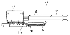
- FIG. 3 is a front view showing an outline of the configuration of the rail device according to the first embodiment.
- the rail device 40 is a device that supports the storage container forming the drawer-type storage chamber so as to be movable back and forth, and includes a bracket 41, a first rail (cabinet rail) 42, and a second rail.
- a rail (middle rail) 43 and a third rail (top rail) 44 are provided.
- the first rail (cabinet rail) 42, the second rail (middle rail) 43, and the third rail (top rail) 44 are each long and are arranged so that their longitudinal directions are the same.
- the bracket 41 is an example of a fixing member in the refrigerator of the present invention.
- the bracket 41 is fastened with a holder rail 48 and a bolt (not shown) with an inner box 70 represented by a dotted line interposed therebetween. Thereby, the rail device 40 is fixed to the inner side surface of the inner box 70.
- bracket 41 two bent portions of the bracket 41 are provided with ribs 41a that connect two non-parallel surfaces existing across the bending position.
- the rib 41a is an example of the reinforcement part in the refrigerator of this invention, and has improved the strength with respect to the bending of the bracket 41.
- the rib 41a may be integrally formed with the bracket 41 by punching out the bracket 41 main body, for example. Further, for example, a separately prepared rib 41 a may be welded to the bracket 41.
- bracket 41 is joined to the side surface of the bracket 41 and the first rail (cabinet rail) 42 so that the height of the rail device 40 is integrated with the first rail (cabinet rail) 42 so that the shape of the fixed portion is formed.
- the first rail and the fixing member can be joined at the same height as the manufactured first rail (cabinet rail) 42.
- the height of the entire rail device increases by the plate thickness of the fixing member, but the side surface of the first rail is joined to the fixing member.
- the fixing member does not exist under the first rail.
- the first rail and the fixing member can be joined at the same height as the rail device (the rail device of the conventional example) in which the height of the entire rail device is integrated with the first rail and the shape of the fixing member is produced. it can.
- bracket 41 it is possible to reduce the amount (length) of the material necessary for manufacturing the bracket 41 as compared with the conventional case when the bracket 41 extends below the first rail (cabinet rail) 42.
- the holder rail 48 is an example of an auxiliary member in the refrigerator of the present invention, and is a member for fixing the rail device 40 to the inner side surface of the inner box 70.
- the holder rail 48 has a flange that extends to a position directly below the lower surface of the first rail (cabinet rail) 42. Thereby, the downward deflection of the first rail (cabinet rail) 42 can be suppressed.
- the holder rail 48 has a flange portion extending at least to the center position of the lower surface of the first rail (cabinet rail) 42, so that the first rail (cabinet rail) 42 has a first lower portion.
- the center position with respect to the bottom surface of the rail (cabinet rail) 42 is received by the holder rail 48.
- the holder rail 48 is disposed on the foam heat insulating material 72 side and the holder rail 48 is embedded in the foam heat insulating material 72, the contact area between the holder rail 48 and the foam heat insulating material 72 is increased. Deformation of the device 40 in the vertical direction can be suppressed by resistance by the foam heat insulating material 72.
- the material strength of the holder rail 48 itself is improved, and the holder rail 48 within the foam heat insulating material 72 is improved.
- the deformation in the vertical direction can be suppressed, and the vertical inclination of the rail device 40 when a load is applied to the rail device 40 is suppressed.
- the opening of the first rail (cabinet rail) 42 is suppressed.
- the holder rail 48 that plays a role of fixing the rail device 40 can be further provided with a role of reinforcing the rail device 40.
- the holder rail 48 has a vertical flange portion on the bottom surface side of the rail device 40 that extends in the same direction as the direction of the force applied to the rail device 40 when the drawer door is pulled out. Strength is improved by increasing the moment of inertia of the longitudinal section as a shape, and the contact area with the foam insulation 72 in the horizontal direction of the vertical flange portion of the holder rail 48 is added, so that the horizontal direction of the vertical flange portion is increased. It is possible to suppress deformation due to contact with the foam heat insulating material 72. In other words, by devising the shape of the holder rail for fixing the rail device to the inner box, the material strength of the holder rail itself is improved and horizontal deformation in the foam insulation of the holder rail is suppressed. Thus, the horizontal inclination of the rail device when a load is applied to the rail device is suppressed.
- the shape of the holder rail 48 for fixing the rail device 40 to the inner box 70 is devised.
- the holder rail 48 is disposed on the side of the foam insulation 72 of the inner box 70 to which the rail device 40 is attached, and at least the first rail (cabinet rail) 42 as a fall prevention portion of the rail device. It was set as the structure which has the flange part extended to the center position of the lower surface of this. Thereby, deformation
- the holder rail 48 which originally plays a role of fixing the rail device 40, can be further provided with a role of reinforcing the rail device 40.
- the first rail (cabinet rail) 42 is an example of the first rail in the refrigerator of the present invention, and the side surface thereof is surface-bonded to the bracket 41. Specifically, the bracket 41 and the first rail (cabinet rail) 42 are joined by spot welding, and the bracket 41 and the first rail (cabinet rail) 42 are connected to the conventional first rail (fixed rail) 131a ( This corresponds to FIG.
- the rail device 40 is configured by previously joining a flat portion of the bracket 41 fixed to the inner box 70 and a flat portion of the outer surface of the first rail (cabinet rail) 42. .
- the flat surface portion constituting the bracket 41 and the flat surface portion constituting the outline of the first rail (cabinet rail) 42 face each other.
- the flat portion of the bracket 41 and the outer flat portion of the first rail (cabinet rail) 42 face each other, and the end portion of the bracket 41 is the outer flat portion of the first rail (cabinet rail) 42. It is not something that is abutted and joined.
- the rail device 40 has the bracket 41 fixed to the inner surface of the inner box 70 and then supports the storage container 63a directly or indirectly on the third rail (top rail) 44 so as to be slidable back and forth. Is.
- the thickness of the material can be easily increased or the material can be changed.
- spot welding In this spot welding, three spots are provided at almost equal intervals with intervals in the longitudinal direction. Specifically, spot welding is provided at three locations, near both ends of the bracket 41 and near the center of the bracket 41.
- the first rail (cabinet rail) 42 has flanges extending upward on the left and right in the longitudinal direction (in FIG. 3, the direction perpendicular to the plane of the paper, the same applies hereinafter).
- the second rail (middle rail) 43 is an example of the second rail in the refrigerator of the present invention.
- the second rail (middle rail) 43 has a I-shaped cross section perpendicular to the longitudinal direction, and has a shape having flanges protruding left and right in the vertical direction.
- the lower flange of the upper and lower flanges is held by the first rail (cabinet rail) 42 so as to be movable in the longitudinal direction.
- the left and right flanges of the first rail (cabinet rail) 42 are extended to a height exceeding the lower flange of the second rail (middle rail) 43, as shown in FIG. Thereby, the second rail (middle rail) 43 is movable and stably held.
- 3rd rail (top rail) 44 is an example of the 3rd rail in the refrigerator of this invention, and is a rail which supports the container which forms drawer-type storage rooms, such as the storage container 63a.
- the third rail (top rail) 44 has the same cross-sectional shape as the first rail (cabinet rail) 42, and holds the flange on the second rail (middle rail) 43 so as to be movable in the longitudinal direction.
- each of the first rail (cabinet rail) 42 and the third rail (top rail) 44 can move the second rail (middle rail) 43 by a plurality of bearings 45 held by a ball gauge 46.
- the bearing 45 is an example of a sliding member in the refrigerator of the present invention.
- first rail (cabinet rail) 42 holds the portions centering on the lower flange among the upper and lower flanges of the second rail (middle rail) 43 by a plurality of bearings 45.
- first rail (cabinet rail) 42 supports the second rail (middle rail) 43 from three directions via a plurality of bearings 45 in the cross section so that the second rail (middle rail) 43 is elongated. Holds movable in the direction.
- the third rail (top rail) 44 holds the portion centering on the upper flange of the second rail (middle rail) 43 with a plurality of bearings 45. Further, the third rail (top rail) 44 also supports the second rail (middle rail) 43 from three directions via a plurality of bearings 45 in the cross section so that the second rail (middle rail) 43 is elongated. Holds movable in the direction.
- the second rail (middle rail) 43 is It can move on the (cabinet rail) 42 in its longitudinal direction.
- the third rail (top rail) 44 is movable on the second rail (middle rail) 43 in the longitudinal direction. That is, the third rail (top rail) 44 can move in the longitudinal direction on the first rail (cabinet rail) 42 via the second rail (middle rail) 43.
- FIG. 4 is a first perspective view showing the appearance of the rail device according to the first embodiment.
- FIG. 5 is a second perspective view showing the appearance of the rail device according to the first embodiment.
- the third rail (top rail) 44 moves relative to the first rail (cabinet rail) 42 via the second rail (middle rail) 43. That is, the rail device 40 as a whole expands and contracts.
- the lengths of the first rail (cabinet rail) 42, the second rail (middle rail) 43, and the third rail (top rail) 44 are stored when the storage container 63a is pulled out to the maximum pull-out position.
- the rear end side of the container 63 a is a length that is positioned forward of the front surface of the door directly above the vegetable compartment 56.
- the refrigerator 51 of the present embodiment in which the vegetable compartment 56 that is a drawer-type storage room can be fully opened does not lose convenience such as smoothness of drawer due to various technical features of the rail device 40.
- the left and right flanges of the first rail (cabinet rail) 42 are both extended to a height exceeding the flange below the second rail (middle rail) 43.
- the cross section perpendicular to the longitudinal direction of the first rail (cabinet rail) 42 is approximately bilaterally symmetric.
- first rail (cabinet rail) 42 is surface-joined with a bracket 41 fixed to the inner box 70.
- the cross section perpendicular to the longitudinal direction of the first rail (cabinet rail) 42 is approximately bilaterally symmetric as compared with the conventional first rail (fixed rail) 4031a of FIG. ) 43 to the first rail (cabinet rail) 42 is applied almost equally to the left and right, so that it is difficult to open against a load having a component in the interior direction.
- the load applied to the first rail (cabinet rail) 42 is transmitted to the bracket 41 joined to the first rail (cabinet rail) 42 by spot welding.
- the bent portion of the bracket 41 is provided with a plurality of ribs 41a as shown in FIGS. Therefore, compared with the case where there is no rib 41a, the bending amount with respect to the same load is suppressed.
- a part of the portion of the holder rail 48 that is bent toward the inner side extends below the first rail (cabinet rail) 42.
- the length of the portion of the holder rail 48 that is bent toward the inner side is approximately the length beyond the center of the first rail (cabinet rail) 42 in the left-right direction.
- first rail (cabinet rail) 42 is approximately bilaterally symmetric, the formability during roll molding is good. That is, it is easy to manufacture with high accuracy.
- the joint between the first rail (cabinet rail) 42 and the bracket 41 is spot-welded, so that it is locally welded, and compared with the case where welding is continuously performed in the longitudinal direction, Deformation (distortion) in the longitudinal direction of the rail device due to heating is suppressed, and even when a large-capacity storage chamber is supported so as to be fully opened, the usability of the storage chamber is maintained.
- the fall prevention portion of the rail device is obtained by previously joining the flat portion of the bracket 41 fixed to the inner box 70 and the flat portion of the outer wall of the first rail (cabinet rail) 42.
- the first rail (cabinet rail) 42 applies a force to the first rail (cabinet rail) 42 via the second rail (middle rail) 43 movably installed in the groove. Even if it is a case where it becomes a cross-sectional shape which is hard to open when supported, and supports a large-capacity storage chamber so that it can be fully opened, deformation of the rail device is suppressed, and the usability of the storage chamber is maintained.
- the first rail (cabinet rail) 42 is symmetrical when viewed from the front, the first rail (cabinet rail) 42 is produced with high accuracy, for example, by roll forming a plate material. Easy to do.
- the length of the bracket 41 in the depth direction can be determined regardless of the length of the first rail (cabinet rail) 42.
- the amount (length) of the material necessary for manufacturing the rail device may be reduced as compared with the conventional case. Is possible.
- the two rails sandwiching the second rail (middle rail) 43 of the first rail (cabinet rail) 42 are both equal to or higher than a predetermined height, and the rib 41a is provided at the bent portion of the bracket 41.
- the holder rail 48 has a shape capable of supporting the first rail (cabinet rail) 42 from below, so that deformation of the rail device 40 such as tilting, bending or bending of the rail device 40 is suppressed.
- the rail device of the freezer compartment 57 can have the same configuration as the vegetable compartment 56.
- the refrigerator 51 according to the first embodiment is a refrigerator including a drawer-type storage room, and is a refrigerator that does not lose the usability even if the capacity of the storage room is large.
- the first rail (cabinet rail) 42 is a separate body from the bracket 41 for fixing the rail device 40 to the inner box 70. Therefore, the bracket 41 need only have a length necessary for fixing the rail device 40 to the inner box 70. Thereby, the effect that the material required for the rail apparatus 40 is reduced is also exhibited.
- first rail (cabinet rail) 42 and the bracket 41 are joined by spot welding, but may be joined continuously in the longitudinal direction by arc welding or the like.
- the upper surface of the flange portion of the holder rail 48 and the lower surface of the inner box 70 are in direct contact with each other without using a heat insulating material.
- This deformation can be suppressed by the holder rail 48 which is a strong material without using the flexible foam heat insulating material 72, and the reinforcing effect of the holder rail 48 can be brought about reliably.
- the holder rail 48 can be directly attached to the inner box surface, the attachment position of the holder rail 48 can be easily regulated, and the holder rail 48 can be reliably attached to the required predetermined position. The reinforcing effect can be obtained with certainty.
- the lower surface of the first rail (cabinet rail) 42 and the upper surface of the inner box 70 are in direct contact with each other, so that when a load is applied to the rail device 40, the lower surface of the first rail (cabinet rail) 42. If there is a space between the inner box 70 and the upper surface of the inner box 70, the rail device will continue to be deformed without any obstruction.
- the lower surface of the first rail (cabinet rail) 42 and the upper surface of the inner box 70 are in direct contact with each other, so that there is a space between the lower surface of the first rail (cabinet rail) 42 and the upper surface of the inner box 70.
- the deformation of the rail device 40 due to the load can be suppressed by the holder rail 48 attached in the foam heat insulating material 72 of the inner box 70, and the reinforcing effect of the holder rail 48 can be brought about reliably. .
- the lower surface of the first rail (cabinet rail) 42 and the upper surface of the inner box 70 may not necessarily be in direct contact with each other due to the effects of variations in the rail device mounting process and product variations. If the clearance between the lower surface of the first rail (cabinet rail) 42 and the upper surface of the inner box 70 is 1 mm or less, the deterioration in the reinforcing effect of the holder rail 48 is small compared to the case of direct contact, and the first rail (cabinet) If the clearance between the lower surface of the (rail) 42 and the upper surface of the inner box 70 is 1 mm or less, substantially the same effect as the direct contact can be obtained.
- the rail apparatus 40 in this Embodiment 1 shown in FIGS. 3-5 is a case where the storage room has a large capacity and the storage room is pulled out until the storage room is fully opened. It is an example of the rail apparatus which can hold
- the rail structure of the present invention is not limited to a refrigerator, and is applicable not only to a system kitchen, a cupboard, a dishwasher, a desk, etc., but also to all having a drawer mechanism.
- the end of the third rail (top rail) 44 is connected to the door 63, and the storage container 63a is supported by the third rail (top rail) 44. That is, the storage container 63 a is directly supported by the third rail (top rail) 44.
- the storage container 63 a may be supported by a door frame (not shown) connected to the door 63. That is, the storage container 63 a is indirectly supported by the third rail (top rail) 44.
- the door frame is formed of, for example, a metal material such as iron, and is fixed to the door 63 using screws or the like (not shown) substantially perpendicular to the surface of the door 63 on the storage chamber side. It is connected. Further, the door frame is joined to the third rail (top rail) 44.
- the user in order to enable the container to be attached and detached and cleaned at any time at the same use position as in the normal use state in which the stored item is taken in and out, the user can perform one action (one time) pull-out operation.
- the design concept of the dimensional relationship in the front-rear direction with the refrigerator body so that it can be pulled out to the position where the container can be attached and detached in the upward direction by simply performing A precision rail device, a refrigerator body that makes good use of the rail device, and a fixing and mounting structure with little variation on the door are required.
- the present invention provides a built-in configuration of a drawer rail device to a refrigerator that can comprehensively solve this problem.
- FIG. 6 is a cross-sectional view seen from the side of the refrigerator according to Embodiment 1 of the present invention.
- FIG. 7 is a cross-sectional view seen from the front of the refrigerator in the first embodiment of the present invention.
- FIG. 8 is an exploded view of the refrigerator according to Embodiment 1 of the present invention.
- FIG. 9 is an exploded view of the rail device according to the first embodiment of the present invention.
- FIG. 10 is a front view showing a schematic configuration of the rail device according to the first embodiment of the present invention.
- a heat insulating box 619 of the refrigerator 618 is obtained by filling a foam heat insulating material 622 between an inner box 620 and an outer box 621, has a front opening 619a, and partition walls 623, 623a. , 624 form a refrigerator compartment 625, a switching chamber 626, a vegetable compartment 627, and a freezer compartment 628 from above.
- both side surfaces of the partition wall 624 have open portions 624a, and the partition wall 624 is filled with a foam heat insulating material 622 in the same manner as the heat insulating box 619.
- the vegetable room 627 arranged at the upper part of the partition wall 624 has a cooling temperature of about 5 ° C.
- the freezing room 628 arranged at the lower part of the vegetable room 627 has a cooling temperature of about ⁇ 20 ° C.
- the vegetable compartment 627 and the freezer compartment 628 are drawer-type storage rooms each having a front opening 619a and a vegetable compartment drawer door 629 and a freezer compartment drawer door 630.
- the vegetable compartment 627, the vegetable compartment drawer door 629, and the freezer compartment drawer are also provided.
- Each door 630 is connected by a rail member 631 so that it can be drawn and slid in the front-rear direction.
- the switching chamber 626 is also a drawer type storage chamber.
- the upper end of the vegetable room drawer door 629 is set to be located at 1000 mm or less corresponding to the height of the human elbow from the floor surface.
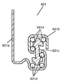
- the rail member 631 includes a first rail (fixed rail) 631a, a third rail (moving rail) 631b, and a second rail provided between the first rail (fixed rail) 631a and the third rail (moving rail) 631b.
- a plurality of rotation support members that support the engagement of the rail (intermediate traveling rail) 631c, the second rail (intermediate traveling rail) 631c, the first rail (fixed rail) 631a, and the third rail (moving rail) 631b. It consists of a bearing 631d.
- the first rail (fixed rail) 631a, the third rail (moving rail) 631b, the second rail (intermediate running rail) 631c, and the bearing 631d are assembled in advance, and the first rail (fixed rail) 631a is installed in the inner box.
- the third rail (moving rail) 631b is connected to and supported by a vegetable compartment drawer door 629 and a freezer compartment drawer door 630 which are arranged vertically via a partition wall 624.
- the container 632 of each storage chamber is supported by the third rail (moving rail) 631b of the rail member 631 after the rail member 631 is fixed to the inner box 620, and in synchronization with the drawer of each storage chamber drawer door in the front-rear direction.
- the container 632 can be easily attached and detached in the upward direction when it moves back and forth together with the third rail (moving rail) 631b and when each storage room drawer door is fully opened.
- the operation when opening such a drawer type door can be pulled out to the maximum open position by a single drawer operation performed by the user.
- the rail member 631 may be disposed on the partition wall 624.
- first rail (fixed rail) 631a and the third rail (moving rail) 631b, and the first rail (fixed rail) 631a and the third rail (moving rail) 631b are arranged via bearings 631d.
- the rail member 631 composed of the second rail (intermediate running rail) 631c is incorporated in advance, and the clearance between the respective rails is set to a minimum for the first time by using the pre-installed high-precision rail. be able to.
- the depth (P dimension) of the container 632 is set to be greater than the depth (H dimension), and the withdrawal allowance (L dimension) of the vegetable room drawer door 629 and the freezer compartment drawer door 630 is the depth (P dimension) of the container 632. It is set larger.
- the inner wall surface (c surface) on the back side of the container 632 is the front opening 619a, that is, the front opening surface (a It is set so as to be located in front of the surface.
- the depth (P dimension) of the container 632 provided in the vegetable compartment 627 is about 60% with respect to the depth dimension (M dimension) of the heat insulation box 619, and it is a drawer-type storage chamber with a deep depth. .
- this vegetable room 627 is a storage room having the largest capacity among a plurality of drawer-type storage rooms.
- the total length (D dimension) of the third rail (moving rail) 631b of the rail member 631 is set larger than the total length (E dimension) of the first rail (fixed rail) 31a. Yes.
- the total length (F dimension) of the second rail (intermediate travel rail) 631c disposed via the bearing 631d between the first rail (fixed rail) 631a and the third rail (moving rail) 631b is It is substantially the same as the rail (fixed rail) 631a (E dimension).
- the tips of the first rail (fixed rail) 631a and the third rail (movable rail) 631b are substantially flush with the third rail (movable rail).
- the rear end of 631b and the second rail (intermediate running rail) 631c are substantially flush with each other.
- the rear end of the third rail (moving rail) 631b is substantially in the same position as the front end of the first rail (fixed rail) 631a.
- the second rail (intermediate travel rail) 631c slides so that the lap allowance of the two rails (intermediate travel rail) 631c with the first rail (fixed rail) 631a and the third rail (movable rail) 631b has substantially the same size. Operate.
- left and right rail members 631 fixed to the both side wall surfaces of the inner box 620 have a symmetrical shape, and exhibit better sliding performance by providing both left and right.
- a small container 632a shallower than the container 632 is installed on the upper part of the container 632 of the freezer compartment 628, so that food can be stored separately.
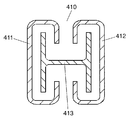
- the fixed positions of the first rails (fixed rails) 631a of the pair of left and right rail members 631 are restricted via the inner box 620 by the connecting members 633 that are position restricting portions.
- the connecting member 633 has a horizontal section 633a and an H-shaped cross section having a vertical section 633b at both ends of the horizontal section 633a.
- the horizontal section 633a is fixed inside the partition wall 624 between the upper partition wall 624b and the lower partition wall 624c.
- the vertical portion 633b protrudes from the opening 624a of the partition wall 624 to the outside of the partition wall 624 and is disposed on the side of the inner box 620 that is filled with the foam insulation 622, so that the connecting member 33 is not exposed to each storage chamber. It has become.
- both ends of the vertical portion 633b reach the vicinity of the center in the vertical direction of the vegetable compartment 627 and the freezing compartment 628, respectively, and the first rail (fixed rail) 631a of the left and right rail members 631 in each storage chamber is the vertical portion 633b. It is fixed to the fixing portion 633c, and at least the fixing portion 633c of the vertical portion 633b is in contact with the surface of the inner box 620 on the side filled with the foam heat insulating material 622. Further, the left and right vertical portions 633b are provided with holes 633d.
- the connecting member 633 When the connecting member 633 becomes larger, it is divided into a plurality of front and rear parts, each having a horizontal portion 633a, a vertical portion 633b, and a fixing portion 633c, and if necessary, a hole 633d is provided, the connecting member 633 is integrated. The same effect as that obtained can be obtained.
- the bearing 631d may be a rotation support member, and for example, a roller or the like may be used.
- the third rail (moving rail) 631b and the second rail (intermediate running rail) 631c of the rail member 631 provided on both sides of each storage room rotate the bearing 631d. By doing so, it slides smoothly toward the front side.
- the container 632 supported by the rail member 631 is also pulled out to the front, so that the object to be cooled stored in the container 632 can be taken out and a new object to be cooled can be stored.
- first rail (fixed rail) is fixed by fixing the high-precision rail member 631 in which the first rail (fixed rail) 631a and the third rail (moving rail) 631b are assembled in advance to both side walls of the inner box 620.
- the clearance between 631a and the third rail (moving rail) 631b can be reduced, and a drawer with little backlash can be configured.
- the variation in the mounting can be reduced by reducing the clearance, it is possible to suppress the appearance defect such as the inclination due to the mounting failure of the drawer door and the non-uniform spacing with other drawer doors. These effects are more effective as the allowance for the rail member 631 is larger.
- the inner wall surface (c surface) on the back side of the container 632 is positioned in front of the front opening surface (a surface) of the heat insulating box 619 when fully opened.
- the moving rail and the fixed rail as described in the background art are separate bodies, and are provided on the door side after the groove of the fixed rail provided on the heat insulating box side.
- the storage chamber has a large drawer allowance. Even when applied to the above, sufficient reliability can be ensured.
- the back side of the container 632 in the maximum open position of the vegetable compartment 627 which is the drawer-type storage chamber with the largest capacity among the plurality of drawer-type storage chambers provided in the heat insulation box 619, the back side of the container 632
- the inner wall surface (c surface) of the heat insulation box 619 is located in front of the front opening surface (a surface).
- the depth (P dimension) of the container 632 with which the vegetable compartment 627 was equipped is about 60% with respect to the depth dimension (M dimension) of the heat insulation box 619, and depth is. Deep drawer storage room.
- the first rail (fixed rail) 631a and the third rail (moving rail) 631b are assembled in advance.
- the rail member 631 By applying the rail member 631 with high accuracy, it can be pulled out smoothly to the back of the container 32 provided in the drawer-type storage chamber. Thereby, the storability of the user's refrigerator can be improved, and a user-friendly refrigerator can be provided.
- the ratio of the depth (P dimension) of the container 632 provided in the vegetable compartment 627 to the depth dimension (M dimension) of the heat insulation box 619 is in the range of 55% or more and 90% or less, the deep type By opening the upper surface of the container in this range with a large withdrawal allowance, the user's usability is greatly improved as compared with the conventional case.
- the refrigeration cycle parts such as a compressor, a cooler, and a condenser are not arranged behind the drawer-type storage chamber or are thinned even if arranged. It is easy to realize with a refrigerator and is easy to differentiate compared to conventional refrigerators.
- the ratio does not exceed 80%, the structure and rail specifications related to securing the strength against the load on the drawer-type container can be handled within a relatively reasonable range, and the cost burden is reduced. it can.
- the vegetable room 627 which is a drawer-type storage room, can be pulled out to the maximum open position by a single drawer operation performed by the user.
- the third rail Since the moving rail 631b can move, the operation force of the drawer can be reduced and the usability can be improved.
- the width dimension or parallelism of the pair of left and right rail members 631 can be held as prescribed, and the connecting member 633
- the clearance between the first rail (fixed rail) 631a and the third rail (moving rail) 631b is set small by suppressing dimensional changes due to heat shrinkage or the like during cooling after the foamed heat insulating material 622 is filled in the heat insulating box 619.
- the dimensional accuracy between the pair of left and right rail members 631 can be kept high. It can be increased by some connecting member 633. In addition, it is possible to ensure operation reliability over a long period of time.
- the second rail (intermediate running rail) 631c is provided, and the total length (D dimension) of the third rail (moving rail) 631b of the rail member 631 is set larger than the first rail (fixed rail) 631a (E dimension). Yes. Therefore, when the vegetable compartment drawer door 629 and the freezer compartment drawer door 630 are fully opened, the withdrawal allowance (L dimension) can be set larger than the depth of the container 32 (P dimension). ) Can be positioned in front of the front opening surface (a surface) of the heat insulating box 619.
- the container room 632 linked to the vegetable room drawer door 629 and the freezer compartment drawer door 630 can be pulled out to the back of the container 32, and the container 32 can be overlooked. Loss due to forgetting to use the object to be cooled in 632 can be prevented. Furthermore, since the container 632 can be easily attached to and detached from the rail member 631, the usability can be improved.
- the user can easily attach and detach the container when removing the container to clean the container, etc.
- User convenience can be significantly improved.
- the rear side of the container 632 is located at the maximum open position of the vegetable compartment 627, which is the drawer-type storage chamber having the largest capacity among the plurality of drawer-type storage chambers provided in the heat insulating box 619. It is assumed that the inner wall surface (c-plane) is positioned in front of the front opening surface (a-plane) of the heat insulating box 619 and that the food can be easily taken out and the container 632 can be easily attached and detached. However, among the plurality of drawer-type storage chambers, such a container is provided in the drawer-type storage chamber where the effect is most required. A reasonable configuration can be selected for a refrigerator with many drawer storage rooms.
- the need for a relatively compact and small-capacity drawer container is reduced, and when the door located directly above is a double-folded type rotary door instead of a drawer door, the upper door is opened.
- the container can be attached / detached relatively easily if it is present, and it is difficult to feel much inconvenience even if the container is not configured as described above, considering the balance with the attachment / detachment opportunity.
- the back side of the container 632 In the maximum open position of the vegetable compartment 627 which is the drawer-type storage chamber with the largest capacity among the plurality of drawer-type storage chambers provided in the heat insulation box 619, the back side of the container 632
- the inner wall surface (c surface) of the heat insulation box 619 is located in front of the front opening surface (a surface).
- the rear end surface of the container 632 is provided in a storage room located above and adjacent to the drawer-type storage room.
- the container 632 when the user removes the container 632 in order to clean the container 632, the container 632 can be easily attached and detached without any obstacles simply by lifting the container 632 upward, and food and the like are stored. It is possible to greatly improve the convenience of the user when keeping the refrigerator, which is easily contaminated with dirt, clean by washing or washing.
- the small container 632a shallower than the container 632 is installed on the upper part of the container 632 of the freezer compartment 628, the food can be stored separately, and the usability is further improved.
- the positional relationship between the inner wall surface on the back side of the shallow accessory container 632a, the front opening surface (a surface) of the heat insulating box 619, the rear end surface, and the front surface (b surface) of the door interposed at the top is the same as that of the container 632 described above. By setting to, a similar effect can be obtained for the shallow accessory container 632a.
- the upper end of the vegetable room drawer door 629 is set to 1000 mm or less lower than the position of the human elbow, food in and out of the container 632 can be easily taken in and out.
- connecting member 633 is not exposed in each storage chamber, it is possible to suppress the reduction of the storage volume as compared with the case where the connecting member 633 is disposed in each storage chamber.
- the connecting member 633 is formed of a metal material, it is possible to prevent injuries due to the edge of the end face, so that safety can be improved, and furthermore, the edge deletion processing of the end face can be abolished, so that cost can be reduced.
- connecting member 633 that connects the left and right first rails (fixed rails) 631a is embedded in the foam heat insulating material 622 of the heat insulating box 619, it is possible to prevent condensation and frost formation of the connecting member 633 when the refrigerator 618 is used. Further, since the connecting member 633 does not come into contact with air, the corrosion resistance of the connecting member 633 can be improved, and the rust prevention treatment of the connecting member 633 can be reduced, so that the cost can be reduced.
- the foam heat insulating material 622 is provided around the connecting member 633, the mounting strength of the connecting member 633 can be improved, and the reliability of position regulation and the mounting strength of the rail member 631 can be improved.
- the partition wall 624 that partitions the heat insulation box 619 into the vegetable compartment 627 and the freezing compartment 628 is provided, and the connecting member 633 that connects the left and right first rails (fixed rails) 631a is provided inside the partition wall 624. In the case of having a plurality of storage spaces, it is possible to suppress the reduction of the storage internal volume due to the connection member 633 being arranged.
- the vegetable chamber 627 and the freezing chamber 628 adjacent to each other are provided with rail members 631 and the first rail (fixed rail) 631a of each rail member 631 is integrally fixed by the connecting member 633, a plurality of storages are stored. The operability of the room can be improved at the same time.
- the connecting member 633 has an H-shaped cross section having vertical portions 633b at both ends, and the vegetable chamber 627 and the first rail (fixed rail) 631a of the rail member 631 of the freezing chamber 628 that are vertically adjacent to the vertical portion 633b are integrated. Since the first rails (fixed rails) 631a of the plurality of rail members 631 are fixed to one connecting member 633, the cost can be reduced by reducing the number of components.
- the connecting member 633 has a vertical portion 633b at both ends and a cross-sectional H shape having a horizontal portion 633a therebetween, and the connecting member 633 has a cross-sectional H shape having vertical portions 633b at both ends.
- the connecting member 633 provided with the hole 633d is enlarged in the left and right vertical portions 633b, the connecting member 633 is divided into a plurality of front and rear portions, each having a horizontal portion 633a, a vertical portion 633b, and a fixing portion 633c. Accordingly, if the hole 633d is provided, the same effect as that obtained when the connecting member 633 is integrated can be obtained.
- the horizontal portion 633a of the connecting member 633 may not necessarily be necessary depending on the design of the refrigerator.
- the connecting member 633 does not have the horizontal portion 633a, and the left and right sides of the inner box 620 are filled with the foam heat insulating material 622. It may have a pair of vertical portions 633b.
- the vertical portion 633b is not connected to each other and is a separate body, but even in that case, the left and right mounting of the rail member 631 can be performed by positioning the vertical portion 633b on the left and right by providing a position restricting portion in some way. Position accuracy can be improved, and a high-precision rail member can be provided while saving resources by eliminating the horizontal portion 633a.
- the holes 631c are provided in the vertical portions 631b at both ends of the connecting member 633, heat transfer from the connecting member 633 is suppressed when the temperature zones of the plurality of storage chambers are different, and condensation on the storage chamber side having a high temperature zone is suppressed. And increase in power consumption due to heat leakage can be suppressed.
- the amount of heat transfer can be effectively reduced by providing a plurality of holes 631c provided in the vertical portion 631b to such an extent that the strength can be maintained.
- the connecting members 633 are used particularly when the rail members 631 are used in a large refrigerator. Since the connecting member 633 can be reduced in size by dividing into a plurality of parts, the cost can be reduced.
- the rail member 631 is shared by the vegetable compartment 627 and the freezer compartment 628.
- the use of materials formed by different storage chambers depending on the storage configuration of actual use further reduces the cost. Reliability can be improved.
- the connecting member 633 is made of a material having a linear expansion coefficient of 1.0 to 3.0 ⁇ 10 ⁇ 6 cm / cm ⁇ ° C. and a thermal conductivity of 0.1 to 0.2 W / m ⁇ K.
- metals are 1.0 to 3.0 ⁇ 10 ⁇ 6 cm / cm ⁇ ° C. and resins are 1.0 to 15.0 ⁇ 10 ⁇ 5 cm / cm ⁇ ° C.
- the thermal conductivity is 1.0 to 400.0 W / m ⁇ K for metals and 0.1 to 0.2 W / m ⁇ K for resins.
- the connecting member 633 is made of metal having a low linear expansion coefficient, and prevents condensation on the storage room side having a high temperature zone.
- resins having a low thermal conductivity it is desirable to use resins having a low thermal conductivity. Moreover, you may integrate and use both with respect to several storage chambers.
- the connecting member 633 has a horizontal portion 633a and an H-shaped cross section having vertical portions 633b at both ends of the horizontal portion 633a, and the rail members 631 of the vegetable compartment 627 and the freezing compartment 628 are integrally formed.
- a connecting member having vertical portions at both ends may be used in each of the vegetable compartment 627 and the freezing compartment 628. In this case, in a refrigerator in which the vegetable compartment 627 and the freezer compartment 628 are not provided vertically, it is possible to provide an easy-to-use drawer with little operational force even if a load is applied with little backlash.
- heat transfer from the connecting member is further suppressed when the temperature zones of the plurality of storage chambers are different compared to when a plurality of rail members are fixed to one connecting member, and condensation on the storage chamber side having a high temperature zone is prevented. And increase in power consumption due to heat leakage can be suppressed.
- the first rail (fixed rail) of the pair of left and right rail members may be connected by a plurality of connecting members.
- the connecting member can be reduced in size by dividing the connecting member into a plurality of parts, the cost can be reduced and the weight can be reduced.
- FIG. 11 is a front view showing a schematic configuration of the rail device according to the second embodiment of the present invention.
- the rail device 80 according to the second embodiment differs from the rail device 40 according to the first embodiment in the joining position of the first rail (cabinet rail) 42 and the bracket 84.
- the bracket 84 is L-shaped as a whole. Further, the lower surface of the first rail (cabinet rail) 42 and the bracket 84 are joined by spot welding (portion surrounded by a dotted line in FIG. 11).
- the bracket 84 has a structure that supports the first rail (cabinet rail) 42 from below.
- a load is applied mainly from a perpendicular direction to the joint surface between the first rail (cabinet rail) 42 and the bracket 84. Therefore, the reliability of the joint portion is improved.
- the bracket 84 has one less bent portion than the bracket 41 in the first embodiment. That is, the bracket 84 can be manufactured with fewer steps than the bracket 41.
- the rail device 80 according to the second embodiment mainly has high strength and reliability with respect to a load in the vertical direction.
- the rail device 80 supports a large-capacity storage room so as to be fully opened, the deformation of the rail device 80 is suppressed, and the usability of the storage room is maintained.
- FIG. 12 is a front view showing a schematic configuration of the rail device 81 according to the third embodiment of the present invention.
- the rail device 81 in the third embodiment includes a first rail (cabinet rail) 86 having the same shape as a conventional fixed rail 4031a (see FIG. 42).
- the first rail (cabinet rail) 86 is directly fixed to the inner box 70.
- first rail (cabinet rail) 86 is not symmetrical with the first rail (cabinet rail) 42, unlike the first rail (cabinet rail) 42.
- the vertical dimension of the second rail (middle rail) 85 is longer than the vertical dimension of the second rail 43 in the first embodiment.
- the cross-sectional secondary moment of the second rail (middle rail) 85 is larger than the cross-sectional secondary moment of the second rail (middle rail) 43. That is, the second rail (middle rail) 85 has higher bending strength than the second rail (middle rail) 43.
- the secondary moment of inertia about the centroid axis required for the second rail (middle rail) 85 is calculated.
- the actual dimension in the vertical direction of the second rail (middle rail) 85 By making the actual dimension in the vertical direction of the second rail (middle rail) 85 longer than the dimension thus determined, the actual moment of inertia of the cross section becomes the value of the calculated moment of inertia of the cross section. Bigger than.
- the falling prevention portion of the rail device has a predetermined secondary moment in a cross section perpendicular to the longitudinal direction because the vertical dimension of the second rail (middle rail) 85 is longer than the predetermined dimension.
- FIG. 13 is a front view which shows the structure outline
- the rail device 82 in the fourth embodiment includes a first rail (cabinet rail) 86 having the same shape as a conventional fixed rail 4031a (see FIG. 42).
- the flange on the inner box 70 side (left side in FIG. 13) of the third rail (top rail) 44a is longer than the third rail 44 in the first embodiment (encircled by the dotted line in FIG. 13). portion).
- the third rail (top rail) 44 a has downward flanges on the left and right in the longitudinal direction across the flange on the second rail 43.
- the flange on the inner surface side (the left side in FIG. 13) of the inner box 70 extends below the other flange.
- the cross-sectional secondary moment of the third rail (top rail) 44 a is larger than the cross-sectional secondary moment of the third rail 44. That is, the third rail (top rail) 44 a has higher bending strength than the third rail 44.
- the rail device 82 supports the large-capacity storage room so as to be fully opened, the deformation of the rail device 82 is suppressed, and the usability of the storage room is maintained.
- the fall prevention portion of the rail device is configured such that the flange of the third rail (top rail) 44a is a flange that faces downward in the longitudinal direction across the flange on the second rail (middle rail) 43.
- the flange on the inner side surface of the left and right flanges is configured to extend below the other flange so that the second moment of the cross section of the third rail (top rail) 44a is increased.
- FIG. 14 is a front view showing a configuration outline of the rail device according to the fifth embodiment of the present invention.
- the rail device 83 in the fifth embodiment has an L-shaped bracket 84 as a whole, like the rail device 80 in the second embodiment described above.
- the lower surface of the first rail (cabinet rail) 42 and the bracket 84 are joined by spot welding, and the bracket 84 is configured to support the first rail (cabinet rail) 42 from below.
- the support form of the first rail (cabinet rail) 42 and the third rail (top rail) 44 with respect to the second rail (middle rail) 43a is different from the support form in the first to fourth embodiments.
- each portion of the second rail (middle rail) 43 a is an upper flange 43 b, a base plate 43 c, and a lower flange 43 d, the following support form is provided.
- the first rail (cabinet rail) 42 supports a portion centering on the lower flange 43d from four directions in cross section via a plurality of bearings 45. Thereby, the 2nd rail (middle rail) 43 is hold
- the third rail (top rail) 44 supports a portion centering on the upper flange 43b from four directions in cross section through a plurality of bearings 45. Thereby, the 2nd rail (middle rail) 43 is hold
- the second rail (middle rail) 43a is supported from more directions in relation to the first rail (cabinet rail) 42 and the third rail (top rail) 44, respectively. Has been.
- the rail device 83 supports the large-capacity storage room so as to be fully opened, the deformation of the rail device 83 is suppressed, and the usability of the storage room is maintained.
- the second rail (middle rail) 43a is supported from three directions as long as it is supported from at least one of the first rail (cabinet rail) 42 and the third rail (top rail) 44 from four directions. Compared to the case, the strength of the rail device 83 is improved.
- the holder rail 48 shown in FIG. 3 may be used for fixing the rail device 80 in the second embodiment to the inner box 70. By doing so, deformations such as inclination of the rail device 80 toward the inner side and deflection in the vertical direction are suppressed.
- the same effect can be obtained by using the holder rail 48 for fixing the rail device to the inner box 70 in the third to fifth embodiments.
- a rib similar to the bracket 41 in the first embodiment may be provided in the bent portion of the first rail (cabinet rail) 86 in the third embodiment.
- strength with respect to the bending of the 1st rail (cabinet rail) 86 improves.
- the lower surface of the first rail (cabinet rail) 42 and the L-shaped bracket 84 are joined by spot welding.
- the 2nd rail (middle rail) 85 shown in Embodiment 3 with a long vertical dimension and the 3rd rail (top rail) 44a with a long flange part shown in Embodiment 4 are used.
- the second rail (middle rail) 85 is supported from four directions in the cross section from the first rail (cabinet rail) 42 and the third rail (top rail) 44a.
- a plurality of bearings 45 are arranged.
- a rail device that realizes an easy-to-use drawer-type storage room can also be provided by combining various technical features that enhance the reliability of the rail device.
- the various rail devices in the first to fifth embodiments can be used as a drawer mechanism in the ice making chamber 54 and the switching chamber 55 which are not only the vegetable chamber 56 and the freezing chamber 57 but also a drawer-type storage chamber.
- FIG. 15 is a front view of the refrigerator according to the sixth embodiment of the present invention.
- the refrigerator 151 is a refrigerator including a double door and includes a storage compartment partitioned into a plurality of parts in the heat insulating box 152.
- the storage room is provided with a refrigerating room 153, an ice making room 154, an ice making room 154, a switching room 155, a vegetable room 156, and a freezing room 157 that can change the room temperature.
- a heat insulating door filled with a foam heat insulating material such as urethane is provided in the opening of each storage room.
- the refrigerator compartment 153 is provided with a left door 160a and a right door 160b that close the opening of the heat insulation box 152 so as to be opened and closed.
- the ice making room 154, the switching room 155, the vegetable room 156, and the freezing room 157 are provided with a drawer type door 161, a door 162, a door 163, and a door 164, respectively.
- the storage rooms other than the refrigerator compartment 153 are drawer-type storage rooms.
- the heat insulating box 152 is a foam heat insulating material in a space formed by an inner box 170 obtained by vacuum forming a resin body such as ABS and an outer box 171 using a metal material such as a pre-coated steel plate. It is comprised with the heat insulation wall with which 172 was filled.
- a cooler (not shown) and a fan (not shown) are provided on the rear side of the vegetable room 156 and the freezing room 157, and a compressor (not shown) installed at the lower part of the main body of the refrigerator 151.
- the cooler is driven, and the air cooled from the cooler is sent to each storage chamber.
- cooling is controlled to a predetermined temperature for each storage chamber.
- FIG. 16 is a perspective view showing a state in which the vegetable room of the refrigerator in the sixth embodiment of the present invention is pulled out.
- the vegetable compartment 156 is a drawer-type storage room, and the storage container 163 a forming the vegetable compartment 156 is provided in a heat-insulating box 152 by the rail device 140.
- the storage container 163a is provided with a third rail (top rail) 144 that is movable in the front-rear direction of the refrigerator 151 via the second rail (middle rail) 143, on its left and right sides (front side and back side in FIG. 14). ) Is supported.
- a third rail (top rail) 144 that is movable in the front-rear direction of the refrigerator 151 via the second rail (middle rail) 143, on its left and right sides (front side and back side in FIG. 14). ) Is supported.
- the second rail (middle rail) 143 is movably supported by a first rail (cabinet rail) 142 not shown in FIG.
- the first rail (cabinet rail) 142 is fixed to the inner side surface of the inner box 170.
- the end of the third rail (top rail) 144 that supports the left and right sides of the storage container 163a is connected to the door 163.
- the maximum pull-out distance of the door 163 is a length that allows the storage container 163a to be completely opened.
- the maximum pull-out distance is such that when the vegetable compartment 156 is fully opened, the end surface (the left side in FIG. 14) of the storage container 163a is positioned in front of the front surfaces of the door 161 and the door 162 immediately above the vegetable compartment 156. Length.
- the storage container 163a does not interfere with the upper door 161 and the door 162 when the storage container 163a is taken out and attached. Therefore, the storage container 163a can be easily taken out and attached.
- the maximum pull-out distance is determined similarly to the vegetable compartment 156, and the user can easily attach and detach the storage container forming the freezer compartment 157.
- the vegetable room 156 and the freezing room 157 are pulled out to such a position when the rail device 140 extends.
- FIG. 17 is a cross-sectional view showing a schematic configuration of the rail device 140 according to the sixth embodiment of the present invention.
- the rail device 140 is a device that supports a storage container forming a drawer-type storage chamber so as to be movable back and forth, and includes a first rail (cabinet rail) 142 and a second rail (middle rail). ) 143 and a third rail (top rail) 144.
- the first rail (cabinet rail) 142, the second rail (middle rail) 143, and the third rail (top rail) 144 are each elongated, and are arranged so that their longitudinal directions are the same.
- the first rail (cabinet rail) 142 is fastened with the holder rail 148 and the screw 150a with the inner box 170 in between.
- the rail device 140 is fixed to the inner surface of the inner box 170.
- the holder rail 148 is an example of an auxiliary member in the refrigerator of the present invention, and is a member for fixing the rail device 140 to the inner side surface of the inner box 170.
- the holder rail 148 is disposed on the foam heat insulating material 172 side. Specifically, the holder rail 148 is embedded in the foam heat insulating material 172.
- the holder rail 148 has a flange portion 148 a that extends to a position directly below the lower surface of the first rail (cabinet rail) 142. Thereby, the downward deflection of the first rail (cabinet rail) 142 can be suppressed.
- the holder rail 148 has a flange portion 148 a that extends to at least the center position of the lower surface of the first rail (cabinet rail) 142.
- the holder rail 148 has a vertical flange portion 148e in which the front end of the flange portion 148a is bent substantially perpendicularly downward in the vertical direction.
- the first rail (cabinet rail) 142 is an example of the first rail in the refrigerator of the present invention.
- the rail device 140 has a first rail (cabinet rail) 142 fixed to the inner side surface of the inner box 170 and supports the storage container 163a directly or indirectly on the third rail (top rail) 144 to slide back and forth. It is possible to move.
- the cross-sectional shape of the first rail (cabinet rail) 142 is not symmetrical.
- the second rail (middle rail) 143 is an example of the second rail in the refrigerator of the present invention.
- the second rail (middle rail) 143 has a I-shaped cross section perpendicular to the longitudinal direction, and has a shape having flanges protruding left and right in the vertical direction.
- the lower flange of the upper and lower flanges is held by the first rail (cabinet rail) 142 so as to be movable in the longitudinal direction.
- the third rail (top rail) 144 is an example of the third rail in the refrigerator of the present invention, and is a rail that supports a container that forms a drawer-type storage chamber such as the storage container 163a.
- the third rail (top rail) 144 has a U-shaped cross section, and holds the flange on the second rail (middle rail) 143 so as to be movable in the longitudinal direction.
- each of the first rail (cabinet rail) 142 and the third rail (top rail) 144 can move the second rail (middle rail) 143 by a plurality of bearings 145 held by a ball gauge 146.
- the bearing 145 is an example of a sliding member in the refrigerator of the present invention.
- first rail (cabinet rail) 142 holds the portions centering on the lower flange among the upper and lower flanges of the second rail (middle rail) 143 by a plurality of bearings 145.
- first rail (cabinet rail) 142 supports the second rail (middle rail) 143 from three directions via a plurality of bearings 145 in the cross section, thereby extending the second rail (middle rail) 143 in the longitudinal direction. Holds movable in the direction.
- the third rail (top rail) 144 holds the portion centering on the upper flange of the second rail (middle rail) 143 with a plurality of bearings 145. Further, the third rail (top rail) 144 also supports the second rail (middle rail) 143 from three directions via a plurality of bearings 145 in the cross section so that the second rail (middle rail) 143 is elongated. Holds movable in the direction.
- the first rail (cabinet rail) 142, the second rail (middle rail) 143, and the third rail (top rail) 144 are combined in this way, so that the second rail (middle rail) 143 is the first rail.
- (Cabinet rail) 142 is movable in the longitudinal direction.
- the third rail (top rail) 144 is movable on the second rail (middle rail) 143 in the longitudinal direction. That is, the third rail (top rail) 144 can move in the longitudinal direction on the first rail (cabinet rail) 142 via the second rail (middle rail) 143.
- the rail device 4031 when a load is applied to the conventional rail device 4031, the rail device 4031 tends to deform in the direction of the arrow. That is, the fixed rail 4031a tries to open its mouth.
- the holder rail 148 has a flange portion 148 a extending at least to the center position of the lower surface of the first rail (cabinet rail) 142, so that the first rail (cabinet rail) 142 is In the lower part, the center position with respect to the bottom surface of the first rail (cabinet rail) 142 is received by the holder rail 148.
- the holder rail 148 is arrange
- the holder rail 148 that originally plays a role of fixing the rail device 140 can be made to further play a role of reinforcing the rail device 140.
- the holder rail 148 has a vertical flange portion 148e on the bottom surface side of the rail device 140 that extends in the same direction as the direction of the force applied to the rail device 140 when the drawer door is pulled out.
- the strength of the vertical rail section 148e is increased and the contact area of the vertical flange portion 148e of the holder rail 148 with the foam heat insulating material 172 in the horizontal direction is added, so that the vertical flange portion 148e is added.
- the deformation (indicated by the arrow in FIG. 17) that tends to move in the horizontal direction can be suppressed by the resistance due to contact with the foam heat insulating material 172.
- the material strength of the holder rail itself is improved and horizontal deformation in the foam insulation of the holder rail is suppressed.
- the horizontal inclination of the rail device when a load is applied to the rail device is suppressed.
- the shape of the holder rail 148 for fixing the rail device 140 to the inner box 170 is devised, that is, in the sixth embodiment, the rail device 140 is used as the rail device 140 for preventing the rail device from falling.
- the rail device 140 is configured to have the flange portion 148a that is disposed on the foam insulation 172 side of the attached inner box 170 and extends at least to the center position of the lower surface of the first rail (cabinet rail) 142. Deformation such as the inclination of the rail device 140 when a load is applied to the rail device 140 is suppressed.
- the holder rail 148 that essentially plays the role of fixing the rail device 140 can be further given the role of reinforcing the rail device 140.
- FIG. 18 is a perspective view showing the appearance of the rail device according to the sixth embodiment of the present invention.
- the third rail (top rail) 144 moves relative to the first rail (cabinet rail) 142 via the second rail (middle rail) 143. That is, the rail device 140 as a whole expands and contracts.
- the storage container 163 a supported by the third rail (top rail) 144 is pulled out of the heat insulating box 152. That is, the vegetable room 156 is fully opened.
- the lengths of the first rail (cabinet rail) 142, the second rail (middle rail) 143, and the third rail (top rail) 144 are stored when the storage container 163a is pulled out to the maximum pull-out position.
- the rear end side of the container 163a is a length that is positioned forward of the front surface of the door immediately above the vegetable compartment 156.
- the refrigerator 151 according to the sixth embodiment in which the vegetable compartment 156 that is a drawer-type storage room can be fully opened does not lose the usability such as smoothness of the drawer due to various technical features of the rail device 140. .
- FIG. 19 is a perspective view showing the attachment state of the holder rail in the sixth embodiment of the present invention. As shown in FIG. 19, the holder rail 148 is attached to the back side surface of the inner box 170.
- the fixing portion 148b of the auxiliary member for fixing to the inner box 170 provided on the holder rail 148 and the hole provided in the inner box 170 are combined and fixed by the screw 150b.
- a foam heat insulating material 172 such as urethane is foamed and filled in a gap between the inner box 170 and the outer box 171, so that the holder rail 148 is embedded in the foam heat insulating material 172 in a state of being fixed to the back surface of the inner box 170.
- the holder rail 148 is more firmly fixed as the foam heat insulating material 172 is solidified.
- the rail device 140 is arranged in the inner box 170, and a hole (not shown) provided in the first rail (cabinet rail) 142 and a fixing portion 148c of the rail device provided in the holder rail 148 are combined,
- the rail device 140 is fixed to the inner box 170 by being fixed by screws 150a.
- FIG. 20 is a perspective view showing a holder rail in the sixth embodiment of the present invention.
- the flange portion 148a provided on the holder rail 148 is in a state of receiving a downward load applied to the rail device 140 extending in the longitudinal direction.
- the flange portion 148a causes the flange portion 148a and the side surface 148f of the holder rail 148 to be a mounting surface of the holder rail 148 provided with the fixing portion 148b of the auxiliary member and the fixing portion 148c of the rail device by the load transmitted from the rail device 140.
- the angle formed by the surface to have is a movement that widens and widens. If the angle formed by these two surfaces is increased, the rail device 140 will bend and the operability when opening and closing the drawer door will be impaired.
- the rail device that realizes an easy-to-use drawer-type storage room can be provided by devising the shape of the holder rail 148.
- the holder rail 148 has the flange portion 148a extending to at least the center position of the lower surface of the first rail (cabinet rail) 142, so that the first rail (cabinet rail) 142 has a lower portion.
- the center position of one rail (cabinet rail) 142 is received by the holder rail 148, and the contact area between the holder rail 148 and the foamed heat insulating material 172 is increased, so that the rail device 140 tends to be lowered in the vertical direction. Deformation can be suppressed by resistance by the foam heat insulating material 172.
- the material strength of the holder rail 148 itself is improved, and the holder rail 148 in the foam heat insulating material 172 is improved.
- the deformation in the vertical direction can be suppressed, and the vertical inclination of the rail device 140 when a load is applied to the rail device 140 is suppressed.
- the opening of the first rail (cabinet rail) 142 is suppressed.
- the holder rail 148 that originally plays a role of fixing the rail device 140 can be made to further play a role of reinforcing the rail device 140.
- the holder rail 148 has a vertical flange portion 148e on the bottom surface side of the rail device 140 that extends in the same direction as the direction of the force applied to the rail device 140 when the drawer door is pulled out.
- the strength of the vertical rail section 148e is increased and the contact area of the vertical flange portion 148e of the holder rail 148 with the foam heat insulating material 172 in the horizontal direction is added, so that the vertical flange portion 148e is added.
- the deformation (indicated by the arrow in FIG. 17) that tends to move in the horizontal direction can be suppressed by the resistance due to contact with the foam heat insulating material 172.
- the material strength of the holder rail itself is improved and the horizontal deformation of the holder rail 148 in the foam heat insulating material 172 is improved.
- the horizontal inclination of the rail device when a load is applied to the rail device is suppressed.
- the flange portion 148 a bent to the inner side of the holder rail 148 extends to the center position of the lower surface of the first rail (cabinet rail) 142.
- the length of the flange portion 148a bent to the inner side of the holder rail 148 is preferably longer than the center of the first rail (cabinet rail) 142 in the left-right direction.
- the rail device of the freezer compartment 157 can have the same configuration as the vegetable compartment 156.
- the refrigerator 151 according to the sixth embodiment is a refrigerator including a drawer-type storage room, and is a refrigerator that does not lose usability even if the capacity of the storage room is large.
- the rail device in the sixth embodiment can be used as a drawer mechanism not only in the vegetable room 156 and the freezing room 157 but also in the ice making room 154 and the switching room 155 which are drawer-type storage rooms.
- the attachment position of the holder rail 148 can be easily regulated, and the holder rail 148 can be reliably attached to the required predetermined position. The reinforcing effect can be obtained with certainty.
- the lower surface of the first rail (cabinet rail) 142 and the upper surface of the inner box 170 are in direct contact with each other, so that when a load is applied to the rail device 140, the first rail If there is a space between the lower surface of the (cabinet rail) 142 and the upper surface of the inner box 170, the rail device will continue to be deformed without any obstruction.
- the lower surface of the first rail (cabinet rail) 142 and the upper surface of the inner box 170 are in direct contact with each other, so that there is a space between the lower surface of the first rail (cabinet rail) 142 and the upper surface of the inner box 170.
- the lower surface of the first rail (cabinet rail) 142 and the upper surface of the inner box 170 may not necessarily be in direct contact with each other due to variations in the rail device mounting process, product variations, and the like.
- the gap between the lower surface of the first rail (cabinet rail) 142 and the upper surface of the inner box 170 is 1 mm or less, the deterioration in the reinforcing effect of the holder rail 148 is small compared to the case of direct contact, and the first rail (cabinet) If the clearance between the lower surface of the (rail) 142 and the upper surface of the inner box 170 is 1 mm or less, substantially the same effect as that of the direct contact can be obtained.
- the holder rail 148 has, on the bottom surface side of the rail device 140, a vertical flange portion 148e extending in the same direction as the direction of the force applied to the rail device when the drawer door is pulled out.
- the shape of the holder rail 148 improves the strength by increasing the moment of inertia of the longitudinal section, and the contact area with the foam heat insulating material 172 in the horizontal direction of the vertical flange portion 148e of the holder rail is added.
- the deformation of the vertical flange portion 148e of the holder rail 148 that attempts to move in the horizontal direction can be suppressed by the resistance by the foam heat insulating material 172.
- the material strength of the holder rail 148 itself is improved and the horizontal direction of the holder rail 148 in the foam insulation 172 is increased.
- the horizontal inclination of the rail device when a load is applied to the rail device is suppressed.
- the holder rail 148 is formed of a metal material, so that the strength necessary for the fixing portion 148 c of the rail device provided on the holder rail 148 can be easily secured.
- the rail device that is the purpose of use can be securely fixed. That is, the holder rail 148 that combines both fixing and reinforcement of the rail device can be formed as a single component.
- the holder rail 148 has a reinforcing shape 148d at a bent portion between two planes having an angle, so that the holder rail 148 is a holder when a load is applied to the flange portion 148a of the holder rail 148.
- the deformation of the bent portion of the rail 148 can be suppressed by the shape of the holder rail itself, the strength of the holder rail 148 can be improved, and the deformation of the rail device 140 can be suppressed.
- the holder rail 148 has a shape that can be used for both the left and right sides, it is not necessary to use the right and left holder rails 148 separately when attaching the left and right holder rails 148 to the inner box 170, thereby improving workability and molding the holder rail 148. Therefore, the mold cost can be suppressed.
- a load is applied to the rail device by providing a certain distance between the lower surface 148 g of the vertical flange portion and the inner box 170 facing the lower surface 148 g of the vertical flange portion.
- the deformation of the rail due to the load also affects the holder rail 148, and between the lower surface 148 g of the vertical flange portion of the holder rail 148 and the inner box 170 that tries to deform in the same direction as the load applied to the rail device. Because of the fixed distance, the lower surface 148g of the vertical flange portion and the inner box 170 are not in direct contact with each other, and the foam heat insulating material 172 exists.
- the shape of the surface of the inner box 170 can be satisfactorily maintained without causing damage such as breaking through the inner box 170 at the lower surface 148g of the vertical flange portion of the holder rail 148 due to the deformation of the holder rail 148.
- the fixed distance is 1 mm or more and 5 mm or less. It is preferable.
- FIG. 21 is a cross-sectional view showing a schematic configuration of another rail device according to the sixth embodiment of the present invention.
- the vertical flange portion 148 e is inclined so as to be away from the inner side 170, that is, on the opposite side (left side in FIG. 21). Therefore, when a load is applied to the rail device, the deformation of the rail due to the load also affects the holder rail 148, and the deformation of the vertical flange portion 148e of the holder rail 148 is deformed to the inner side where the inner box 170 exists. Suppress.
- the inner box 170 does not exist more reliably with respect to the traveling direction of the vertical flange portion 148e of the holder rail 148, and the foam heat insulating material 172 exists, and the inner surface of the vertical flange portion 148g is deformed by the deformation of the holder rail 148.
- the shape of the surface of the inner box 170 can be better maintained without causing damage such as breaking through the box 170.
- auxiliary member fixing portions 148b there are two auxiliary member fixing portions 148b on the front side and the rear side for each holder rail 148.
- the fixing portion 148b is fixed to the holder 150b with a screw 150b. Only the front side of the rail 148 is used. This is because the deformation of the rail is hardly deformed downward on the rear side in the longitudinal direction, and the deformation of the holder rail hardly occurs.
- the fixing portion 148b of the auxiliary member is the front side where strength is required. This is because a sufficient reinforcing effect can be obtained even at one location.
- the reason for fixing with the screws 150b is to fix the holder rail 148 to the inner box before foaming.
- the holder rail 148 After filling the foam heat insulating material 172, the holder rail 148 is embedded in the foam heat insulating material 172.
- the holder rail 148 can be securely fixed at the required position even in the inner box before foaming. Therefore, the reinforcing effect of the holder rail 148 can be brought about reliably. Further, as described above, the holder rail 148 is finally attached to the side surface of the inner box 170 and embedded in the foam heat insulating material 172.
- the fixing part 148b of the auxiliary member may be fixed only at one place.
- auxiliary member fixing portions 148b are provided on the front side and the rear side, respectively, for each holder rail 148.
- the auxiliary member fixing portion 148b is fixed with screws 150b. Only the front side of the holder rail 148 is used.
- the rear side of the holder rail 148 may also be fixed with screws 150b.
- auxiliary member fixing portion 148b is located closer to the flange portion 148a than the rail device fixing portion 148c, so that when the rail device is loaded, the deformation of the holder rail 148 is affected by the rail deformation. Can be more effectively suppressed.
- the deformation of the holder rail exerted by the rail deformation is deformed with the fixing portion 148c of the rail device as a fulcrum. Do. The farther the point where the load is applied to the fulcrum, the easier the deformation will occur.
- the fulcrum in the deformation of the holder rail 148 is not the fixed part 148c of the rail device but the fixed part 148b of the auxiliary member, and the fixed part 148b of the auxiliary member is used.
- the fixing device 148c of the rail device is provided at two positions, one on each of the front side and the rear side, for each holder rail 148, and is fixed with two screws 150a.
- the fixing unit 148c of the rail device may be provided at two or more locations, for example, three locations, for example, the front side, the rear side, the middle, and the three rails 150a.
- FIG. 22 is a sectional view showing a schematic configuration of the rail device according to the seventh embodiment of the present invention.
- the rail device in the seventh embodiment is different from the rail device in the sixth embodiment in the configuration of the rail device. Specifically, as shown in FIG. 22, the rail device 200 according to the seventh embodiment is different from the rail device 40 that is vertically stacked in three stages as shown in FIG. 3, for example. , With three rails arranged side by side and in three rows.
- the points different from the sixth embodiment will be mainly described.
- the rail device 200 includes a first rail (fixed rail) 201 provided with flanges 201a extending inwardly on the upper and lower sides of a plate-like body, and a container (not shown).
- the flange 202a is narrower than the height dimension of the first rail (fixed rail) 201 fixed to the outside of a support frame (not shown) that supports the first rail (fixed rail) 201 via the support fitting 206 and outward from the upper and lower sides.
- the extended third rail (movable rail) 202 and the inner and outer rails 201, 202 are smaller than the first rail (fixed rail) 201 and have a height dimension larger than the movable rail 202.
- a second rail (intermediate rail) 203 provided with a flange 203a inward from the upper and lower sides.
- the first rail is fixed to the inner side surface of the inner box, and has a flange portion 201a extending inward on the upper and lower sides of the plate-like body
- the third rail is Extending outwardly from the upper and lower sides of the flange 202a is narrower than the height dimension of the first rail (fixed rail) 201 fixed to the outside of a support frame (not shown) for supporting the container via a support fitting 206.
- the second rail is provided between the first rail (fixed rail) 201 and the third rail (movable rail) 202 and is smaller than the first rail (fixed rail) 201. ) It has a height dimension larger than 202, and has a flange 203a inward from its upper and lower sides.
- the second rail (intermediate rail) 203 is substantially integrated by a ball bearing 204 fitted between the flanges 201a, 203a, 202a of the first rail (fixed rail) 201 and the third rail (movable rail) 202. And is slidable in the first rail (fixed rail) 201 and slides in the second rail (intermediate rail) 203 and the second rail (intermediate rail) 203.
- the third rail (movable rail) 202 is pulled out in two stages.
- the container held on the third rail (movable rail) 202 in the pulled-out state via a support frame has a rear end at the storage chamber by the holding mechanism between the rails 201, 202, 203. Is fully pulled out to the front opening of the fully opened state.
- the first rail (fixed rail) 201 is fastened to the holder rail 205 with screws (not shown) with the inner box 170 in between. Thereby, the rail device 200 is fixed to the inner side surface of the inner box 170.
- the holder rail 205 is an example of an auxiliary member in the refrigerator of the present invention, and is a member for fixing the rail device 200 to the inner side surface of the inner box 170.
- the holder rail 205 is disposed on the foam heat insulating material 172 side. Specifically, the holder rail 205 is embedded in the foam heat insulating material 172.
- the holder rail 205 has a flange portion 205 a that extends to a position directly below the lower surface of the first rail (fixed rail) 201. Thereby, the downward deflection of the first rail (fixed rail) 201 can be suppressed.
- the holder rail 205 has a flange portion 205 a extending at least to the center position of the lower surface of the first rail (fixed rail) 201.
- the holder rail 205 has a vertical flange portion 205e in which the front end of the flange portion 205a is bent substantially perpendicularly downward in the vertical direction.
- the rail device 4031 when a load is applied to the conventional rail device 4031, the rail device 4031 tends to deform in the direction of the arrow. That is, the first rail 4031a tries to open the mouth.
- the holder rail 205 has a flange portion 205 a extending at least to the center position of the lower surface of the first rail (fixed rail) 201, so that the first rail (fixed rail) 201 In the lower part, the center position with respect to the bottom surface of the first rail (fixed rail) 201 is received by the holder rail 205, the holder rail 205 is disposed on the foam heat insulating material 172 side, and the holder rail 205 is the foam heat insulating material.
- the contact area between the holder rail 205 and the foam heat insulating material 172 is increased, and the deformation of the rail device 200 that attempts to fall in the vertical direction is suppressed by the resistance of the foam heat insulating material 172.
- the shape of the holder rail 205 for fixing the rail device 200 to the inner box 170 the material strength of the holder rail 205 itself is improved, and the holder rail 205 in the foam insulation 172 is improved. Vertical deformation can be suppressed.
- the inclination of the vertical direction of the rail apparatus 200 when a load is applied to the rail apparatus 200 is suppressed, and as a result, the opening of the first rail (fixed rail) 201 can be suppressed.
- the holder rail 205 that plays a role of fixing the rail device 200 can be further made to reinforce the rail device 200.
- the holder rail 205 has a vertical flange portion 205e on the bottom surface side of the rail device 200 that extends in the same direction as the direction of the force applied to the rail device 200 when the drawer door is pulled out.
- the vertical moment of inertia of the longitudinal section of the holder rail 205 is increased, and the contact area of the vertical flange portion 205e of the holder rail 205 with the foam heat insulating material 172 in the horizontal direction is added.
- the deformation that tends to move in the horizontal direction can be suppressed by resistance due to contact with the foam heat insulating material 172.
- the material strength of the holder rail itself is improved and horizontal deformation in the foam insulation of the holder rail is suppressed. it can. Thereby, the horizontal inclination of the rail device when a load is applied to the rail device is suppressed.
- the shape of the holder rail 205 for fixing the rail device 200 to the inner box 170 is devised. That is, in the seventh embodiment, the holder rail 205 is disposed on the side of the foam insulation 172 of the inner box 170 to which the rail device 200 is attached, and at least the first rail (fixed rail) as the rail device collapse prevention portion. 201 has a flange portion 205 a extending to the center position of the lower surface of 201. Thereby, deformation
- the holder rail 205 which originally plays a role of fixing the rail device 200, can be further provided with a role of reinforcing the rail device 200.
- the upper surface of the flange portion 205a of the holder rail 205 and the lower surface of the inner box 170 are in direct contact with each other without using a heat insulating material.
- the attachment position of the holder rail 205 can be easily regulated, and the holder rail 205 can be reliably attached to the required predetermined position. The reinforcing effect can be obtained with certainty.
- the lower surface of the first rail (fixed rail) 201 (more specifically, the lower surface of the flange 201a below the first rail (fixed rail) 201) and the upper surface of the inner box 170 Is in direct contact. Therefore, when a load is applied to the rail device 200, if there is a space between the lower surface of the first rail (fixed rail) 201 and the upper surface of the inner box 170, the rail device is not obstructed. Deformation will continue. However, the lower surface of the first rail (fixed rail) 201 and the upper surface of the inner box 170 are in direct contact with each other, so that there is a space between the lower surface of the first rail (fixed rail) 201 and the upper surface of the inner box 170.
- the deformation of the rail device 200 due to the load can be suppressed by the holder rail 205 attached in the foam heat insulating material 172 of the inner box 170, and the reinforcing effect of the holder rail 205 is surely brought about. Can do.
- the lower surface of the first rail (fixed rail) 201 and the upper surface of the inner box 170 may not necessarily be in direct contact with each other due to variations in the rail device mounting process, product variations, and the like. If the gap between the lower surface of the first rail (fixed rail) 201 and the upper surface of the inner box 170 is 1 mm or less, the deterioration in the reinforcing effect of the holder rail 205 is small compared to the case of direct contact, and the first rail (fixed) If the clearance between the lower surface of the (rail) 201 and the upper surface of the inner box 170 is 1 mm or less, the same effect as that of the direct contact can be obtained.
- the holder rail is formed of a metal material, the holder rail has a reinforcing shape at a bent portion between two planes having an angle, and the holder rail has a shape that can be used for both right and left.
- the lengths of the first rail (fixed rail) 201, the second rail (intermediate rail) 203, and the third rail (movable rail) 202 are the same as the length of the storage container when the storage container is pulled out to the maximum drawer position. Is the length that is positioned in front of the front surface of the door directly above the storage chamber.
- the refrigerator according to the seventh embodiment in which the storage room which is a drawer-type storage room can be fully opened does not lose usability such as smoothness of the drawer due to various technical features of the rail device 200.
- FIG. 23 is a cross-sectional view showing a schematic configuration of another rail device according to the seventh embodiment of the present invention.
- the rail device 210 according to the seventh embodiment is similar to the rail device 200 shown in FIG. 22, for example, a rail device 40 vertically stacked in three stages as shown in FIG. 3.
- the rail device 210 has three rails arranged side by side in three rows.
- the second rail (intermediate rail) 213 having an H-shaped cross section is movable with respect to the first rail (fixed rail) 211
- the third rail (movable rail) 212 is the first rail.
- bearings that are sliding members are omitted.
- the holder rail 215 extends to at least the center position of the lower surface of the first rail (fixed rail) 211. , The center position with respect to the bottom surface of the first rail (fixed rail) 211 is received by the holder rail 215 at the lower part of the first rail (fixed rail) 211.
- the holder rail 215 is disposed on the foam heat insulating material 172 side and the holder rail 215 is embedded in the foam heat insulating material 172, the contact area between the holder rail 215 and the foam heat insulating material 172 is increased, and the rail The deformation of the device 210 that is about to go down in the vertical direction can be suppressed by the resistance by the foam heat insulating material 172. That is, by devising the shape of the holder rail 215 for fixing the rail device 210 to the inner box 170, the material strength of the holder rail 215 itself is improved, and the holder rail 215 in the foam heat insulating material 172 is improved.
- the deformation in the vertical direction can be suppressed, and the vertical inclination of the rail device 210 when a load is applied to the rail device 210 is suppressed.
- the opening of the first rail (fixed rail) 211 is suppressed.
- the holder rail 215 that essentially plays the role of fixing the rail device 210 can be further given the role of reinforcing the rail device 210.
- the holder rail 215 has a vertical flange portion 215e on the bottom surface side of the rail device 210 that extends in the same direction as the direction of the force applied to the rail device 210 when the drawer door is pulled out.
- the strength is increased by increasing the moment of inertia of the longitudinal section, and the contact area of the vertical flange portion 215e of the holder rail 215 with the foamed heat insulating material 172 in the horizontal direction is added, so that the vertical flange portion 215e is added.
- the deformation that tends to move in the horizontal direction can be suppressed by resistance due to contact with the foam heat insulating material 172.
- the material strength of the holder rail itself is improved and horizontal deformation in the foam insulation of the holder rail is suppressed.
- the horizontal inclination of the rail device when a load is applied to the rail device is suppressed.
- the holder rail 215 can be directly attached to the inner box surface, it becomes easy to regulate the attachment position of the holder rail 215, and the holder rail 215 can be reliably attached to the predetermined position required. The reinforcing effect can be obtained with certainty.
- the lower surface of the first rail (fixed rail) 211 and the upper surface of the inner box 170 are in direct contact with each other, so that when a load is applied to the rail device 210, the first rail If there is a space between the lower surface of the (fixed rail) 211 and the upper surface of the inner box 170, the rail device will continue to be deformed without any obstruction.
- the lower surface of the first rail (fixed rail) 211 and the upper surface of the inner box 170 are in direct contact with each other, so that there is a space between the lower surface of the first rail (fixed rail) 211 and the upper surface of the inner box 170.
- the lower surface of the first rail (fixed rail) 211 and the upper surface of the inner box 170 may not necessarily be in direct contact with each other due to variations in the rail device mounting process, product variations, and the like.
- the gap between the lower surface of the first rail (fixed rail) 211 and the upper surface of the inner box 170 is 1 mm or less, the deterioration in the reinforcing effect of the holder rail 215 is small compared to the case of direct contact, and the first rail (fixed) If the gap between the lower surface of the (rail) 211 and the upper surface of the inner box 170 is 1 mm or less, substantially the same effect as the direct contact can be obtained.
- a drawer-type door is not provided, but a single-open hinge-type door (rotating door) is provided, and this hinge-type door is opened and opened from the opening of the storage room.
- a single-open hinge-type door rotating door
- this hinge-type door is opened and opened from the opening of the storage room.
- FIG. 24 is a front view of the refrigerator according to the eighth embodiment of the present invention.
- the refrigerator 500 is a refrigerator including two doors, and includes a storage room divided into three in a heat insulating box 570.
- the heat insulation box 570 is constituted by a heat insulation wall in which a foam heat insulation 573 is filled in a space constituted by an inner box 571 obtained by vacuum molding a resin body such as ABS and an outer box 572 using a metal material such as a pre-coated steel plate. Has been.
- the refrigerator 500 includes a refrigerator compartment 510, a vegetable compartment 520, and a freezer compartment 530.
- rectangular dotted lines represent the openings of the respective storage chambers.
- the vegetable compartment 520 accommodates a drawer-type container described later.
- a heat insulating door filled with a foam heat insulating material such as urethane is provided.
- a hinge-type first door 511 that closes the opening of the refrigerator compartment 510 and the vegetable compartment 520 so as to be freely opened and closed is provided.
- the first door 511 is provided with a hinge at the left end thereof, and rotates about a vertical rotation axis.
- the freezer compartment 530 is provided with a second drawer-type door 531.
- the refrigerator compartment 510 is cooled by a direct cooling method, and the vegetable room 520 and the freezing room 530 are cooled by an indirect cooling method.
- FIG. 25 is a longitudinal sectional view of the refrigerator according to the eighth embodiment. As shown in FIG. 25, in the heat insulation box 570, the refrigerator compartment 510 and the vegetable compartment 520 are partitioned by an upper partition 515. Moreover, the vegetable compartment 520 and the freezer compartment 530 are partitioned by a lower partition 525.
- the refrigerator 500 includes two coolers. Specifically, a first cooler 512 is provided on the back side of the back surface 510 a of the refrigerator compartment 510. The inner surface 510 a of the refrigerator compartment 510 is cooled by heat conduction from the first cooler 512. The air in the refrigerator compartment 510 is cooled by the cooled back surface 510a.
- the first cooler 512 includes a cooling pipe 512a and a metal plate 512b.
- the back surface 510a of the refrigerator compartment 510 is directly cooled by a metal plate 512b attached so as to be in contact with the back side of the back surface 510a.
- the refrigerator 500 includes a second cooler 532 on the back side of the back surface of the freezer compartment 530.
- the inside of the freezer compartment 530 is cooled by circulating the cool air discharged from the second cooler 532.
- the cold air discharged from the second cooler 532 is also supplied to the vegetable compartment 520, and is maintained in a temperature zone between, for example, the temperature zone of the refrigerator compartment 510 and the temperature zone of the freezer compartment 530 by opening / closing control of the damper.
- the vegetable compartment 520 accommodates a drawer-type storage case 521, and the user can pull out the storage case 521 by opening the first door 511.
- the storage case 521 described in the eighth embodiment corresponds to the storage container described in the first to seventh embodiments.
- the refrigerator 500 according to the eighth embodiment is characterized in that food and the like can be easily taken in and out of the storage case 521 and the storage case 521 can be easily attached and detached.
- the storage case 521 and its drawer configuration will be described with reference to FIGS. 26 and 27.
- FIG. 26 is an enlarged perspective view showing the appearance of the storage case according to the eighth embodiment.
- the storage case 521 is supported by a rail member 542.
- the rail member 542 is long in the front-rear direction, and is supported so as to be slidable in the front-rear direction by a fixing member 541 fixed in the vegetable compartment 520.
- the storage case 521 has holding portions 523 that protrude outward from the left and right ends, more specifically, at the bottom of the storage case 521 and at both ends in the left-right direction.
- the holding portion 523 is provided with an attachment hole 523a for detachably attaching the storage case 521 to the rail member 542.
- the rail member 542 is provided with a protruding portion 543 that protrudes upward and engages with the mounting hole 523a.
- Each of the protrusions 543 of the left and right rail members 542 of the storage case 521 can be inserted into and removed from the mounting hole 523a.
- the drawer unit 540 supports the storage case 521 so as to be detachable in the vertical direction.
- the storage case 521 is formed of a light-transmitting resin capable of confirming the stored items in the storage case 521 from the side of the storage case 521. That is, the storage case 521 is made of a resin having a relatively high transparency.
- the type and number of food items stored in the storage case 521 can be easily confirmed from the side of the storage case 521.
- an accessory case 522 is detachably attached to the upper part and rear part of the storage case 521.
- the storage case 521 and the accessory case 522 can be used properly.
- the small case 22 suppresses the amount of distortion of the storage case 521 when a heavy food is stored in the storage case 521.
- the drawer unit 540 is composed of left and right rail members 542 and a fixing member 541 of the storage case 521.
- drawer unit 540 described in the eighth embodiment corresponds to the rail device described in the first to seventh embodiments.
- FIG. 27 is a plan sectional view showing the storage case 521 and the drawer unit 540 in the eighth embodiment.
- the drawer unit 540 has a first rail (fixed member) 541 and a rail member 542 disposed on the left and right sides of the storage case 521, respectively.
- Each of the two rail members 542 includes a second rail (middle rail) 542a and a third rail (support rail) 542b.
- the third rail (support rail) 542b is a rail that directly supports the storage case 521, and is slidable in the front-rear direction with respect to the second rail (middle rail) 542a. Further, the second rail (middle rail) 542a is slidable in the front-rear direction with respect to the first rail (fixing member) 541.
- the entire drawing unit 540 can be expanded and contracted in the front-rear direction.
- the maximum pull-out distance of the storage case 521 is a distance that improves the usability of the storage case 521.
- a hinge door (revolving door) with a single opening is provided, and the hinge door is opened and the storage container is pulled out from the opening of the storage room (storage container)
- the storage container is directly or indirectly supported and pulled out by the third rail, and is included in the drawer-type storage chamber.
- FIG. 28 is a front view of the refrigerator according to the ninth embodiment of the present invention.
- the refrigerator 700 is a refrigerator having three doors, and has three storage rooms in the heat insulating box 770.
- the refrigerator 700 includes a refrigerator compartment 710, a vegetable compartment 720 whose room temperature can be changed, and a freezer compartment 730.
- a heat insulating door is provided at the opening of each storage room.
- the refrigerator 700 opens and closes the upper door 711 that opens and closes the opening of the refrigerator compartment 710, the middle door 721 that closes the opening of the vegetable compartment 720, and the opening of the freezer compartment 730. And a lower door 731 that is freely closed.
- rectangular dotted lines represent the openings of the respective storage chambers.
- the upper door 711 and the middle door 721 are hinge type doors, each provided with a hinge at the left end, and rotated around a vertical rotation axis.
- each of the three storage rooms is the same as in the eighth embodiment. That is, the refrigerator compartment 710 is cooled by the direct cooling method, and the vegetable room 720 and the freezing room 730 are cooled by the indirect cooling method.
- a drawer-type storage case (not shown) is accommodated and is detachably supported by a drawer unit (not shown).
- the refrigerator 700 according to the ninth embodiment includes a door in each of the refrigerator compartment 710 and the vegetable compartment 720.
- a hinge door (rotary door) with a single opening is provided, the hinge door is opened, and the storage container is pulled out from the opening of the storage chamber (storage container)
- the storage container is directly or indirectly supported and pulled out by the third rail, and is included in the drawer-type storage chamber.
- the direct cooling method and the indirect cooling method are adopted as the cooling methods for the three storage rooms.
- the cooling method of each storage room is not limited to a specific one.
- all of the refrigerator compartment 510, the vegetable compartment 520, and the freezer compartment 530 may be cooled by an indirect cooling method.
- each storage room is not limited to the type described in the eighth and ninth embodiments.
- the vegetable room 520 and the vegetable room 720 may be storage rooms called variable temperature chambers in which a user can set a temperature zone.
- the hinge type doors such as the first door 511 and the middle door 721 are so-called single-open doors.
- the hinged doors such as the first door 511 and the middle door 721 are double doors in which each of the two door plates arranged on the left and right pivots around a pivot axis near the outer edge. There may be.
- one first door 511 may be constituted by two door plates. The same applies to the middle door 721.
- the effect of suppressing the deformation of the rail device which is the effect of the present invention, is exhibited without depending on the type of storage room, the cooling method, and the like.
- FIG. 29 is a front view of the refrigerator in the tenth embodiment of the present invention.
- the refrigerator 851 is a refrigerator including a double door type door, and includes a plurality of storage compartments within the heat insulating box 852.
- the storage room is provided with a refrigerating room 853, an ice making room 854, an ice making room 854, a switching room 855, a vegetable room 856, and a freezing room 857, which can change the room temperature, from the top.
- a heat insulating door filled with a foam heat insulating material such as urethane is provided in the opening of each storage room.
- the refrigerator compartment 853 is provided with a left door 860a and a right door 860b that close the opening of the heat insulating box 852 so as to be openable and closable.
- a drawer type drawer door 861, a door 862, a door 863, and a door 864 are provided in the ice making room 854, the switching room 855, the vegetable room 856, and the freezing room 857, respectively.
- the storage rooms other than the refrigerator room 853 are drawer-type storage rooms.
- the heat insulating box 852 includes a foam heat insulating material in a space formed by an inner box 870 obtained by vacuum forming a resin body such as ABS and an outer box 871 using a metal material such as a pre-coated steel plate. It is comprised with the heat insulation wall with which 872 was filled.
- a cooler (not shown) and a fan (not shown) are provided on the rear side of the vegetable room 856 and the freezing room 857, and the cooler is driven by a compressor installed at the lower part of the main body of the refrigerator 851. The air cooled from the cooler is sent to each storage room. In addition, cooling is controlled to a predetermined temperature for each storage chamber.
- FIG. 30 is a perspective view showing a state in which the vegetable room of the refrigerator in the tenth embodiment of the present invention is pulled out.
- the vegetable room 856 is a drawer-type storage room, and the container 863a forming the vegetable room 856 is provided in a heat-insulating box 852 by a rail device 840.
- the container 863a is a third rail (top rail) 844 that is a third rail (moving rail) that is movable in the front-rear direction of the refrigerator 851 via a second rail (middle rail) 843 that is an intermediate rail.
- the left and right sides are supported by the door frame 841 joined to each other.
- the second rail (middle rail) 843 is movably supported by a first rail (cabinet rail) 842 (not shown in FIG. 30), which is a first rail (fixed rail), and is also supported by a third rail (top).
- Rail) 844 is movably supported by a second rail (middle rail) 843.
- the first rail (cabinet rail) 842 is fixed to the inner side surface of the inner box 870.
- the first rail (cabinet rail) 842, the third rail (top rail) 844, and the second rail (middle rail) 843 are each supported by a rotation support member (not shown), and the first rail (cabinet rail).
- the first rail (cabinet rail) 842 is fixed to the side wall of the inner box 870 in a state where 842, the third rail (top rail) 844, and the second rail (middle rail) 843 are assembled in advance.
- the door frame 841 that supports the left and right sides of the container 863a is fixedly connected to the drawer door 863 using screws.
- the maximum pull-out distance of the drawer door 863 is a length that allows the container 863a to be completely opened.
- the maximum drawing distance is a length in which the end surface of the container 863a (the left side in FIG. 30) is located in front of the forefront portion of the outer box 871 when the vegetable compartment 856 is fully opened.
- the container 863a does not interfere with the upper drawer door 861 and the drawer door 862 when the container 863a is taken out and attached. Accordingly, the container 863a can be easily taken out and attached.
- the maximum drawing distance is determined similarly to the vegetable compartment 856, and the user can easily attach and detach the container forming the freezer compartment 857.
- the vegetable room 856 and the freezing room 857 are pulled out to such a position when the rail device 840 extends.
- FIG. 31 is a perspective view showing the appearance of the refrigerator rail device according to the tenth embodiment of the present invention.
- the third rail (top rail) 844 moves relative to the first rail (cabinet rail) 842 via the second rail (middle rail) 843. That is, the rail device 840 as a whole expands and contracts.
- the left and right door frames 841 and the third rail (top rail) 844 connected to the drawer door 863 are pulled out.
- the container 863a supported by the door frame 841 joined to the third rail (top rail) 844 is drawn out of the heat insulating box 852. That is, the vegetable room 856 is fully opened.
- first rail (cabinet rail) 842, the second rail (middle rail) 843, and the third rail (top rail) 844 are such that the container 863a is pulled out to the maximum drawing position. Is the length that is positioned forward of the forefront portion 871a of the outer box.
- the refrigerator 851 of the tenth embodiment in which the vegetable room 856 which is a drawer-type storage room can be fully opened loses the usability such as smoothness of the drawer due to various technical features of the rail device 840. Absent.
- FIG. 32 is a side view showing a state in which the vegetable room of the refrigerator in the tenth embodiment of the present invention is pulled out.
- FIG. 33 is a side view of a main part of the rail device for the refrigerator according to the tenth embodiment of the present invention.
- FIG. 34 is a perspective view of relevant parts of the rail device for the refrigerator according to the tenth embodiment of the present invention.
- the container 863a forming the vegetable compartment 856 is provided so as to be able to be taken in and out of the heat insulating box 852 by the rail device 840, and the vegetable compartment 856 is in a state of being fully opened.
- the maximum pull-out distance of the pull-out door 863 is the length that the container 863a is completely opened.
- the maximum drawing distance is a length in which the rear end face of the container 863a is positioned in front of the forefront portion 871a of the outer box when the vegetable compartment 856 is fully opened.
- the container 863a does not interfere with the upper drawer door 861 and the drawer door 862 when the container 863a is taken out and attached. Accordingly, the container 863a can be easily taken out and attached.
- the maximum drawing distance is determined similarly to the vegetable compartment 856, and the user can easily attach and detach the container forming the freezer compartment 857.
- the innermost part which is the storage chamber side end face of the third rail (top rail) 844 is positioned in front of the forefront part 871a of the outer box 871. Since the end surface on the back side of the third rail (top rail) 844 is exposed to the outside of the heat insulation box 852, the exposed portion of the innermost portion (end surface on the storage chamber side) of the third rail (moving rail) It is desirable to protect.
- the innermost portion of the door frame 841 formed of a metal material which is the end surface on the storage chamber side, is positioned in front of the outermost front portion 871a of the outer box. Assuming that the drawer door 863 is closed with a finger placed in the gap between the box and the foremost part 871a, the innermost part of the third rail (moving rail) (end face on the storage room side) It is desirable to protect exposed parts of
- the rail protection component 846 is attached to the end surface of the third rail (top rail) 844 on the storage chamber side.
- the rail protection component 846 may not be able to completely eliminate the gap generated by the storage chamber side end surface of the door frame 841 and the outermost surface portion 871a of the outer box.
- the storage chamber side end surface of the rail protection component 846 attached to the door frame 841 is located outside the forefront portion 871a of the outer box due to the recent increase in storage capacity of the storage chamber.
- the amount of drawer may increase to a position.
- the depth length of the rail protection component 846 cannot be extended. That is, since the depth length of the rail protection component 846 cannot be extended, there is a gap between the innermost portion of the rail protection component 846 and the forefront portion 871a of the outer box when the drawer door 863 is pulled out to the maximum. It will be possible. If the drawer door 863 is closed with the finger placed in the gap, there is a possibility that the finger is pinched between them.
- an upward inclined surface and an outer side are provided on the back side of the rail protection component 846.
- An inclined surface 846a having a shape combined with an inclined surface facing is provided.
- the inclined surface 846a of the rail protection component is separated from the upward inclined surface.
- the shape is combined with the inclined surface. From the gap formed between the innermost part of the rail protection component 846 and the outermost front surface part 871a of the outer box, it is possible to release the finger by pushing it outward along the inclined surface, and the drawer door 863 is closed. The safety at the time can be increased.
- the angle of this inclined surface 846a is an angle of 10 degrees or more and 45 degrees or less. If the angle is less than 10 degrees, the size of the inclined surface 846a provided on the rail protection component 846 increases, so that the size of the rail protection component 846 itself also increases. There is also sex. In addition, since the shape thickness is thin on the tip side of the inclined surface, it is difficult to ensure the strength of the rail protection component 846.
- the inclined surface 846a has a shape in which an upward inclined surface and an outward inclined surface are combined.
- the finger placed on the inclined surface 846a closes the drawer door 863
- the finger slides on the rail protective component 846 and contacts the case placed above the rail protective component 846.
- the outwardly inclined surfaces when the finger placed on the inclined surface 846a closes the drawer door 863, the finger slides on the rail protection component and is lifted upward, and at the same time pushes outward. It is possible to escape and secure more safety.
- the door frame 841 is fixed to the third rail (top rail) 844, and the rail protection component 846 is fixed to the end surface of the door frame 841 on the storage chamber side.
- the rail protection component 846 is fixed to the door frame 841 by inserting the door frame attachment shape 846b provided in the rail protection component 846 into the hole provided in the door frame 841. Since the rail protection component 846 can be fixed to the door frame 841, the drawer door 863 having the door frame 841 and the rail protection component 846 attached thereto can be joined to the rail device 840 in the manufacturing process. The workability can be improved.
- the door frame 841 is inserted into the hook shape provided on the third rail (top rail) 844. Then, the door frame 841 and the third rail (top rail) 844 are fixed using screws. At this time, since the fixed portion between the third rail (top rail) 844 and the door frame 841 has a hook shape, when the drawer door 863 is opened and closed, a hand or the like may hit the hook shape. Even if the hook shape is not used, the fixing portion of the door frame 841 and the third rail (top rail) 844 has a shape that protrudes from the surface, so that a finger or the like may hit when the door is opened or closed.
- the rail protection component 846 protects the storage chamber side end surface of the third rail (top rail) 844 and also covers the fixing portion between the door frame 841 and the third rail (top rail) 844, thereby When opening and closing, it was suppressed that a hand etc. hit the fixed part of door frame 841 and the 3rd rail (top rail) 844.
- the rail protection component 846 has a shape that also covers a coating suspension hole (not shown) provided near the tip of the door frame 841.
- the door frame 841 is made of a metal material and is painted to improve the aesthetics, cleanliness, etc. of the refrigerator.
- a hole (not shown) for suspending the door frame 841 is required at the time of painting.
- a hanging painting work is performed through a rod or the like in the hanging hole for painting. However, at the time of painting, a hanging rod is passed through the hole, so that no paint adheres to the hole, and a burr made of the paint is generated around the hanging hole.
- the rail device 840 installed in the freezer compartment when touched, the moisture contained in the finger by the rail device 840 cooled in the freezing temperature zone may be instantaneously frozen, and the finger may stick to the rail device 840. is there. Furthermore, rust may occur due to moisture or the like adhering to the exposed rail device 840. By attaching the rail protection component 846, the generation of these rusts can be suppressed.
- the rail protection component 846 is substantially the same height as the upper surface 841a of the door frame, and the upper surface 846c of the rail protection component is provided, so that when the container 863a is mounted on the door frame 841, the rail protection component 846 is It is possible to improve the usability without hindering the attachment of 863a.
- the container 863a can be attached to the rail protection component 846 as shown in FIG. It becomes.
- the load of the container 863a can be applied to the door frame 841 and the rail protection component 846 in a balanced manner.
- the durability of the rail device 840 can be improved.
- the container 863a can be attached to the rail protection component 846, the relationship between the depth length of the door frame 841 and the rail protection component 846 can be changed to an optimal balance.
- the rail protection component 846 formed of a resin material is inferior in strength to the door frame 841 formed of a metal material.
- the rail device 840 is a metal material, the length of the door frame 841 is shortened. If sufficient strength is obtained, the depth length of the rail protection component 846 formed of the resin material is increased.
- the weight of the refrigerator can be reduced. That is, the degree of freedom in selecting the lengths of the door frame 841 and the rail protection component 846 is increased.
- the material of the rail protection component 846 is a resin material. Thereby, even if the shape of the rail protection component 846 is complicated, it can be molded and coloring is easy, so that it is not necessary to paint. Further, the rail protection component 846 can be formed in a rounded shape, and since the material itself is elastic, even when a finger or the like comes into contact with the rail protection component 846, The pain can be relieved.
- the rail protection component 846 and the door frame 841 are set to the same color. Thereby, the rail protection component 846 can be installed without making it conspicuous. Moreover, in order to give a clean feeling as an impression in the refrigerator, white is mainly used. For this reason, it is the mainstream to use a door frame 841 painted in white. Since the door frame 841 is white and the container 863a is mainly white, it is desirable that the rail protection component 846 be also white in the tenth embodiment. Therefore, since the resin color itself is white based on the use of polypropylene resin that is generally easily available, the rail protection component 846 can be used without being colored.
- the innermost portion (the end surface on the storage chamber side) of the third rail (top rail) 844 is outside the forefront portion 871a of the outer box 871.
- the rail protection component 846 attached to the end surface on the storage chamber side of the third rail (top rail) 844 is the innermost portion (end surface on the storage chamber side) of the third rail (top rail) 844.
- Protect exposed parts of As a result it is possible to prevent the hand from touching the end surface of the third rail (top rail) 844, improve safety, and even when supporting a large-capacity storage room in a fully openable state, Good usability, safety in use, and aesthetics can be maintained.
- FIG. 35 is a cross-sectional view showing an attached state of the rail protection component and the door frame of the refrigerator rail device according to the tenth embodiment of the present invention.
- FIG. 36 is a perspective view of the rail protection component of the rail device for the refrigerator according to the tenth embodiment of the present invention as seen from the back.
- the rail protection component 846 is attached and fixed to the door frame 841 so as to cover the door frame 841. That is, the direction in which the load is applied and the mounting direction of the rail protection component are the same direction. Accordingly, the rail protection component 846 can be easily attached, and the rail protection component is protected against the load applied from the upper portion of the rail protection component 846 when the container 863a is fixed on the rail protection component 846. The strength of 846 can be secured relatively easily.
- the rail protection component 846 has at least a part of the rail protection component 846 in contact with the third rail (moving rail) 844 (dotted line A portion in FIG. 35, FIG. 36 Dotted line A section).
- the lower surfaces of the ribs 900, 901, 905, and 906 described below are in contact with the upper surface of the third rail (moving rail) 844.
- a rib is provided inside the rail protection component 846. More specifically, on the inner side of the rail protection component 846, ribs 905 and 906 formed integrally with the rail protection component 846 in order from the front (tip of the inclined portion) in parallel with the longitudinal direction (depth direction of the refrigerator). 907 are provided. In addition, on the inner side of the rail protection component 846, the front portion has a predetermined interval in order from the front (tip of the inclined portion) in the longitudinal direction (depth direction of the refrigerator) and the rail protection component 846.
- Ribs 900 and 901 formed integrally are provided, and a predetermined interval is provided in the rear portion in order from the front (tip of the inclined portion) in the direction perpendicular to the longitudinal direction (depth direction of the refrigerator).
- Ribs 902, 903, 904 formed integrally with the rail protection component 846 are provided.
- the deformation of the rail protection component 846 itself can be suppressed, and the rail protection is applied to the load applied from the upper portion of the rail protection component 846 when the container 863a is fixed on the rail protection component 846 by the rib.
- the strength of the component 846 can be easily ensured.
- the ribs 900, 901, 902, 903, and 904 provided in the direction perpendicular to the longitudinal direction of the rail protection component 846 (the depth direction of the refrigerator) are side surfaces to make it difficult to open the side surface 930 of the rail protection component 846 outward. Are connected together. Therefore, the strength of the rail protection component 846 can be easily secured against the load applied from the upper portion of the rail protection component 846, the rail protection component 846 is difficult to come off, and the end face of the rail device is reliably protected. Can do. That is, the rail protection component 846 molded from a resin material is inferior in strength to a door frame molded from a metal material. However, by providing a rib inside the rail protection component 846, the decrease in the strength is compensated. be able to.
- a plurality (specifically, two places) of fitting portions for joining the rail protection component 846 and the door frame 841 are provided in the rail protection component 846.
- fitting portions 910 and 920 are provided in the vicinity of the rear end of the rail protection component 846, and fitting holes are provided at positions corresponding to the fitting portions 910 and 920 in the door frame 841.
- the fitting strength of the rail protection component 846 is improved by fitting the fitting portions 910 and 920 to the fitting holes provided at the corresponding positions, and a load is applied from the left, right, up, down, and diagonal directions.
- the rail protection component 846 is difficult to come off, and the end face of the rail device can be reliably protected.
- the rail protection component 846 has a structure having a space inside (that is, a line contact by a rib), but at least a part of the inside has a space. It is good also as a structure which does not (namely, it is filled with resin and has surface contact).
- FIG. 37 is a sectional view showing an outline of a rail device for a refrigerator in an eleventh embodiment of the present invention.
- the rail device in the eleventh embodiment is different from the rail device in the tenth embodiment in the configuration of the rail device. Specifically, as shown in FIG. 37, the rail device according to the eleventh embodiment is different from the rail device 840 that is vertically stacked in three stages as shown in FIG. 31, for example. It has three rails arranged in three rows.
- differences from the tenth embodiment will be mainly described.
- the rail device 400 includes a first rail (fixed rail) 401 provided with flanges 401a extending inwardly on upper and lower sides of a plate-like body, and a container (not shown).
- the flange 402a is narrower than the height dimension of the first rail (fixed rail) 401 fixed to the outside of a support frame (not shown) that supports the first rail (fixed rail) 401 and is outward from the upper and lower sides.
- the height of the third rail (moving rail) 402 which is provided between the extended third rail (moving rail) 402 and the inner and outer rails 401 and 402, which is smaller than the first rail (fixed rail) 401 and larger than the third rail (moving rail) 402.
- a second rail (intermediate rail) 403 provided with a flange 403a inward from the upper and lower sides thereof.
- the intermediate rail 403 is movable with respect to the first rail (fixed rail) 401, and the third rail (movable rail) 402 is movable with respect to the second rail (intermediate rail) 403. As stretchable.
- FIG. 38 is a cross-sectional view showing an outline of another rail device of the refrigerator in the eleventh embodiment of the present invention.
- the other rail device 410 in the eleventh embodiment is different from the rail device 840 in the tenth embodiment in the configuration of the rail device. Specifically, as shown in FIG. 38, another rail device 410 of the eleventh embodiment is different from a rail device 840 that is vertically stacked in three stages as shown in FIG. Has three rails arranged side by side in three rows.
- differences from the tenth embodiment will be mainly described.
- an intermediate rail 413 having a H-shaped cross section is movable with respect to the first rail (fixed rail) 411, and the third rail (moving rail) 412 is By being movable with respect to the second rail (intermediate rail) 413, it is possible to expand and contract as a whole.
- bearings that are sliding members are omitted.
- the refrigerator has a drawer-type storage room and a drawer door located in front of the storage room, and the longitudinal direction is the same.
- the rail protection component 846 is provided so that the rail protection component attached to the storage chamber side end surface of the third rail (moving rail) It will protect the exposed part of the innermost part (the end face on the storage room side), prevent the hand from touching the end face of the third rail (moving rail), improve safety, and create a large capacity storage room. Support fully open Even if, ease of use of the storage room, safety in use, can hold aesthetic.
- the rail protection component 846 is provided with an inclined surface 846a at the rear end, so that the amount of drawer increases, and the drawer door is extended to a position where the innermost portion of the rail protection component is located outside the frontmost portion of the outer box. Is withdrawn. Therefore, even when a finger is placed in the gap between the innermost part of the rail protection part and the frontmost part of the outer box, the inclined surface allows the finger to be pushed out and the drawer door can be pushed out. Safety when closing can be increased.
- FIG. 39 is a perspective view showing a rail device mounting method according to Embodiment 12 of the present invention.
- the door of the refrigerator is formed of a foam heat insulating material filled between a door outer plate (not shown) and a door inner plate 475.
- the rail device 440 is coupled to the rail fixing component 474 attached to the door inner plate 475.
- the door inner plate 475 may have a shape like the rail fixing component 474, and the door inner plate 475 and the rail fixing component may be integrated into the door inner plate 475.
- the rail device 440 is fixed without using the door frame 841 shown in the tenth embodiment. It is possible to provide the shape of the end face protection of the rail device by covering the rail device 440 with the container 863a, but it is difficult to protect the end face of the rail device 440 only by the container 863a due to the depth dimension in the refrigerator. There is. Further, if the inner end surface of the rail device 440 is protected by the container 863a, it becomes difficult to position the inner end of the container 863a in front of the front surface of the door immediately above the storage chamber, and the container 863a is taken out and attached. At this time, the container 863a interferes with the upper door 861, and the take-out property of the container 863a is deteriorated.
- the safety of the rail device can be ensured regardless of the presence or absence of the container 863a.
- the various rail devices in the tenth to twelfth embodiments can be used not only as a vegetable room 856 and a freezing room 857 but also as a drawer mechanism in an ice making room 854 and a switching room 855 which are drawer-type storage rooms.
- the refrigerator according to the present invention is a refrigerator provided with a drawer-type storage room, and can provide a refrigerator that does not lose usability even if the capacity of the storage room is large. Therefore, it can be applied to various types and sizes of refrigerators for home use and business use.
- the rail device according to the present invention is most suitable as a drawer mechanism for a storage room in various types and sizes of refrigerators for home use and business use, and is not limited to refrigerators.
- the present invention can be applied to kitchens, cupboards, dishwashers, desks, and the like that have a drawer mechanism as well as food.
Landscapes
- Engineering & Computer Science (AREA)
- Chemical & Material Sciences (AREA)
- Combustion & Propulsion (AREA)
- Physics & Mathematics (AREA)
- Mechanical Engineering (AREA)
- Thermal Sciences (AREA)
- General Engineering & Computer Science (AREA)
- Refrigerator Housings (AREA)
Abstract
Description
846 レール保護部品
41,84,541 ブラケット(固定部材)
41a,900,902,905 リブ(補強部)
42,86,142,201,211 第1レール
43,43a,85,143,203,213 第2レール
43b 上フランジ
43c ベースプレート
43d 下フランジ
44,44a,144,202,212 第3レール
45,145,204,631d ベアリング(摺動部材)
46,146 ボールゲージ
48,148,205,215 ホルダレール(補助部材)
51,151,500,618,700,851 冷蔵庫
52,152,570,619,770,852 断熱箱体
53,153,510,625,710,853 冷蔵室
54,154,854 製氷室
55,155,626,855 切換室
56,156,520,627,720,856 野菜室
57,157,530,628,730,857 冷凍室
60a,160a,860a 左扉
60b,160b,860b 右扉
61,62,63,64,161,162,163,164,629,630,861,862,863,864 扉
63a,163a 収納容器
70,170,571,620,870 内箱
71,171,572,621,871 外箱
72,172,573,622,872 発泡断熱材
148a フランジ部
148b 補助部材の固定部
148c レール装置の固定部
148d 補強形状
148e 縦フランジ部
148g 縦フランジ部の下面
205a,215a フランジ部
205e,215e 縦フランジ部
以下、本発明の冷蔵庫の実施の形態1について、図面を参照しながら説明する。
図11は本発明の実施の形態2におけるレール装置の構成概要を示す正面図である。
図12は本発明の実施の形態3におけるレール装置81の構成概要を示す正面図である。
図13は本発明の実施の形態4におけるレール装置の構成概要を示す正面図である。
図14は本発明の実施の形態5におけるレール装置の構成概要を示す正面図である。
以下、本発明の冷蔵庫の実施の形態6について、図面を参照しながら説明する。
図22は本発明の実施の形態7におけるレール装置の構成概要を示す断面図である。
上記した、実施の形態1から7については、引き出し式の扉を引き出すことで、収納容器が引き出される(すなわち、引き出し式の扉と一体に収納容器が引き出される)ものについて説明した。
実施の形態9として、扉を三つ備える冷蔵庫について説明する。実施の形態8と異なるのは、扉を三つ備える点で、異なる点を中心に説明する。図28は本発明の実施の形態9の冷蔵庫の正面図である。
図29は本発明の実施の形態10における冷蔵庫の正面図である。図29に示すように、冷蔵庫851は、観音開き式の扉を備える冷蔵庫であり、断熱箱体852内に複数に区画された貯蔵室を備えている。
図37は本発明の実施の形態11における冷蔵庫のレール装置の概要を示す断面図である。
図39は本発明の実施の形態12おけるレール装置の取り付け方法を示す斜視図である。
Claims (38)
- 内箱と外箱と前記内箱および前記外箱の間に充填された断熱材とにより形成された断熱箱体と、
引出し式の貯蔵室と、を備える冷蔵庫であって、
前記貯蔵室内に、長尺状の、第1レール、第2レールおよび第3レールと、を有して収納容器を前後に移動可能に支持するレール装置を備え、
前記レール装置は、前記レール装置の倒れ防止部を備え、前記第3レールに前記収納容器を支持して前後に摺動可能にした
冷蔵庫。 - 前記第2レールは、左右に突出したフランジを長手方向の上下に有し、
前記第1レールは、前記第2レールの下のフランジを越える高さまで延設されたフランジを長手方向の左右に有して摺動部材を介して移動可能に保持され、前記第3レールは、前記第2レールの上のフランジを摺動部材を介して移動可能に保持され、
前記レール装置は、前記内箱の内側面に固定部材を固定した上で前記第3レールに直接的又は間接的に前記収納容器を支持して前後に摺動可能にするとともに、
前記レール装置の倒れ防止部は、前記内箱に対して固定される前記固定部材の平面部と前記第1レールの外郭の平面部とが予め接合されることによって構成された
請求項1に記載の冷蔵庫。 - 前記第1レールの側面が前記固定部材と接合されている
請求項2に記載の冷蔵庫。 - 前記第1レールの下面が前記固定部材と接合されている
請求項2に記載の冷蔵庫。 - 前記固定部材は、少なくとも1箇所、折り曲げられた部分を有し、
前記折り曲げられた部分を挟んで存在する平行ではない2つの面を接続する補強部を有する
請求項2に記載の冷蔵庫。 - 前記第2レールは、上下方向の寸法が所定の寸法より長いことにより、長手方向に垂直な断面における断面2次モーメントが所定の値より大きい
請求項2に記載の冷蔵庫。 - 前記第3レールは、前記第2レールの上のフランジを挟んで長手方向の左右に下向きのフランジを有し、
前記左右のフランジのうちの前記内側面側のフランジは、他方のフランジよりも下方まで延設されている
請求項2に記載の冷蔵庫。 - 前記第1レールおよび前記第3レールのうち少なくとも一方は、前記第2レールを、長手方向に垂直な断面において四方向から支持することにより前記第2レールを前記長手方向に移動可能に保持する
請求項2に記載の冷蔵庫。 - 前記第2レールは、左右に突出したフランジを長手方向の上下に有し、
前記第1レールは、前記内箱の内側面に固定されており、前記第2レールの下のフランジを越える高さまで延設されたフランジを長手方向の一方に有して摺動部材を介して移動可能に保持され、
前記第3レールは、前記第2レールの上のフランジを摺動部材を介して移動可能に保持され、
前記レール装置は、前記内箱の内側面に前記第1レールを固定した上で前記第3レールに直接的又は間接的に前記収納容器を支持して前後に摺動可能にするとともに、
前記レール装置の倒れ防止部は、前記第2レールの上下方向の寸法が所定の寸法より長いことにより、前記長手方向に垂直な断面における断面2次モーメントが所定の値より大きい構成とした
請求項1に記載の冷蔵庫。 - 前記第2レールは、左右に突出したフランジを長手方向の上下に有し、
前記第1レールは、前記内箱の内側面に固定されており、前記第2レールの下のフランジを越える高さまで延設されたフランジを長手方向の一方に有して摺動部材を介して移動可能に保持され、
前記第3レールは、前記第2レールの上のフランジを摺動部材を介して移動可能に保持され、
前記レール装置は、前記内箱の内側面に前記第1レールを固定した上で前記第3レールに前記収納容器を支持して前後に摺動可能にするとともに、
前記レール装置の倒れ防止部は、前記第3レールのフランジを前記第2レールの上のフランジを挟んで前記長手方向の左右に下向きのフランジとし、前記左右のフランジのうちの前記内側面側のフランジは、他方のフランジよりも下方まで延設される構成とした
請求項1に記載の冷蔵庫。 - 前記内側面を挟んで、前記レール装置とは反対側に、前記レール装置を前記内箱に固定するための補助部材を備え、
前記補助部材は、前記第1レールの下面の直下まで延設されることにより前記第1レールの下方への変形を抑制するフランジを有する請求項2に記載の冷蔵庫。 - 前記第1レール、前記第2レール、および前記第3レールそれぞれの長さは、前記収納容器が最大引き出し位置まで引き出された場合に、前記収納容器の奥端辺が、前記貯蔵室の直上部の扉の前面より前方に位置させる長さである
請求項2に記載の冷蔵庫。 - 前記第1レールと前記固定部材との接合は、スポット溶接とした
請求項3または4に記載の冷蔵庫。 - 前記第2レールは、左右に突出したフランジを長手方向の上下に有し、
前記第1レールは、前記内箱の内側面に固定されており、前記第2レールの下のフランジを越える高さまで延設されたフランジを長手方向の一方に有して摺動部材を介して移動可能に保持され、
前記第3レールは、前記第2レールの上のフランジを摺動部材を介して移動可能に保持され、
前記内側面を挟んで、前記レール装置とは反対側に、前記レール装置を前記内箱に固定するための補助部材を備え、
前記レール装置は、前記内箱の内側面に前記第1レールを固定した上で前記第3レールに前記収納容器を支持して前後に摺動可能にするとともに、
前記レール装置の倒れ防止部は、前記補助部材を前記レール装置が取り付けられた内箱の断熱材側に配置するとともに、少なくとも前記第1レールの下面の中心位置まで延設されたフランジ部を有する構成とした
請求項1に記載の冷蔵庫。 - 前記補強部材の前記フランジ部の上面と前記内箱の下面とが、直接に接している
請求項14に記載の冷蔵庫。 - 前記第1レールの下面と前記内箱の上面とが、直接に接している
請求項14に記載の冷蔵庫。 - 前記補助部材は、前記レール装置の底面側に、前記引出扉が引き出された際に前記レール装置に加わる力の向きと同方向に伸びた縦フランジ部を有した
請求項14に記載の冷蔵庫。 - 前記補助部材は、金属材料によって成形された
請求項14に記載の冷蔵庫。 - 前記補助部材は、角度を持った2平面間の曲げ部に、補強形状を有した
請求項14に記載の冷蔵庫。 - 前記補助部材は、金属材料によって成形された前記補助部材は、左右兼用である形状をした
請求項14に記載の冷蔵庫。 - 前記縦フランジ部の下面と前記縦フランジ部の下面に対向する前記内箱との間に、一定の距離を持たせた
請求項17に記載の冷蔵庫。 - 前記縦フランジ部は、庫内側とは反対側に傾斜させた
請求項17に記載の冷蔵庫。 - 前記第1レール、前記第2レール、および前記第3レールそれぞれの長さは、前記収納容器が最大引き出し位置まで引き出された場合に、前記収納容器の奥端辺が、前記貯蔵室の直上部の扉の前面より前方に位置させる長さである
請求項14に記載の冷蔵庫。 - 前記第3レールの前記貯蔵室側端面にレール保護部品を備えた
請求項2に記載の冷蔵庫。 - 前記レール保護部品は、後方端部に傾斜面を設けた
請求項24に記載の冷蔵庫。 - 前記傾斜面は、10度以上45度以下の角度である
請求項25に記載の冷蔵庫。 - 引出扉と、
前記引出扉に固定された扉フレームを備え、
前記扉フレームは前記第3レールに固定され、前記レール保護部品は前記扉フレームの前記貯蔵室側端面に固着された
請求項24に記載の冷蔵庫。 - 前記レール保護部品は、前記第3レールと前記扉フレームとの固定部を保護した
請求項27に記載の冷蔵庫。 - 前記レール保護部品は、前記扉フレームを塗装するために前記扉フレームに設けられた吊り穴を保護した
請求項27に記載の冷蔵庫。 - 前記レール保護部品は、樹脂材料を用いて形成された
請求項24に記載の冷蔵庫。 - 前記レール保護部品は、前記扉フレームと同系色で合わせた
請求項27に記載の冷蔵庫。 - 前記レール保護部品の上面は、前記扉フレームの上面と同一高さとした
請求項27に記載の冷蔵庫。 - 前記第3レールと前記第1レールと前記第2レールそれぞれの長さは、前記容器が最大引出し位置まで引出された場合に、前記容器の奥端辺が、前記外箱の最前面部より前方に位置させる長さである
請求項24に記載の冷蔵庫。 - 前記レール保護部品は、前記扉フレームの上から被せるようにして、前記扉フレームに取り付け固定した
請求項27に記載の冷蔵庫。 - 前記レール保護部品の一部を、前記第3レールに接触させた
請求項24に記載の冷蔵庫。 - 前記レール保護部品の内側にリブを設けた
請求項24に記載の冷蔵庫。 - 前記レール保護部品と前記扉フレームとを接合する勘合部を、前記レール保護部品に複数設けた
請求項27に記載の冷蔵庫。 - 内箱と外箱と前記内箱および前記外箱の間に充填された断熱材とにより形成された断熱箱体と、引き出し式の前記貯蔵室と、を備える冷蔵庫に取り付け可能であり、前記貯蔵室を形成する収納容器を前後に移動可能に支持するレール装置であって、
前記内箱の内側面に固定された固定部材と、長手方向が同一になるように配置された、長尺状の、第1レール、第2レールおよび第3レールとを有し、
前記第2レールは、左右に突出したフランジを前記長手方向の上下に有し、下のフランジは前記第1レールに前記長手方向に移動可能に保持されており、
前記第1レールは、前記固定部材に接合されており、前記第2レールの下のフランジを越える高さまで延設されたフランジを前記長手方向の左右に有し、
前記第3レールは、前記第2レールの上のフランジを前記長手方向に移動可能に保持し、かつ、前記収納容器を支持する
レール装置。
Priority Applications (5)
| Application Number | Priority Date | Filing Date | Title |
|---|---|---|---|
| BRPI0907964A BRPI0907964B1 (pt) | 2008-02-29 | 2009-02-27 | refrigerador |
| EP09714681.5A EP2249111B1 (en) | 2008-02-29 | 2009-02-27 | Rail device and refrigerator using the same |
| US13/202,942 US9332840B2 (en) | 2008-02-29 | 2009-02-27 | Rail device and refrigerator using the same |
| CN2009801116765A CN101981395B (zh) | 2008-02-29 | 2009-02-27 | 导轨装置和使用导轨装置的冷藏库 |
| JP2010500570A JP5633368B2 (ja) | 2008-02-29 | 2009-02-27 | レール装置とこれを用いた冷蔵庫 |
Applications Claiming Priority (8)
| Application Number | Priority Date | Filing Date | Title |
|---|---|---|---|
| JP2008049087 | 2008-02-29 | ||
| JP2008-049087 | 2008-02-29 | ||
| JP2008-126775 | 2008-05-14 | ||
| JP2008126775 | 2008-05-14 | ||
| JP2008191947 | 2008-07-25 | ||
| JP2008-191947 | 2008-07-25 | ||
| JP2008234711A JP4353315B1 (ja) | 2008-07-25 | 2008-09-12 | 冷蔵庫 |
| JP2008-234711 | 2008-09-12 |
Publications (1)
| Publication Number | Publication Date |
|---|---|
| WO2009107388A1 true WO2009107388A1 (ja) | 2009-09-03 |
Family
ID=42830473
Family Applications (1)
| Application Number | Title | Priority Date | Filing Date |
|---|---|---|---|
| PCT/JP2009/000873 WO2009107388A1 (ja) | 2008-02-29 | 2009-02-27 | レール装置とこれを用いた冷蔵庫 |
Country Status (7)
| Country | Link |
|---|---|
| US (1) | US9332840B2 (ja) |
| EP (1) | EP2249111B1 (ja) |
| JP (1) | JP5633368B2 (ja) |
| CN (3) | CN102767933B (ja) |
| BR (1) | BRPI0907964B1 (ja) |
| TW (1) | TWI448655B (ja) |
| WO (1) | WO2009107388A1 (ja) |
Cited By (9)
| Publication number | Priority date | Publication date | Assignee | Title |
|---|---|---|---|---|
| WO2012117732A1 (ja) * | 2011-03-02 | 2012-09-07 | パナソニック株式会社 | 冷蔵庫 |
| JP2012193949A (ja) * | 2011-03-02 | 2012-10-11 | Panasonic Corp | 冷蔵庫 |
| JP2012229826A (ja) * | 2011-04-25 | 2012-11-22 | Panasonic Corp | 冷蔵庫 |
| US20120306338A1 (en) * | 2010-03-25 | 2012-12-06 | Panasonic Corporation | Refrigerator |
| WO2013042338A3 (en) * | 2011-09-22 | 2013-06-20 | Panasonic Corporation | Refrigerator |
| CN104913588A (zh) * | 2015-06-16 | 2015-09-16 | 无锡海达尔精密滑轨有限公司 | 用于冰箱的搁物架轨道系统 |
| JP2017026165A (ja) * | 2015-07-15 | 2017-02-02 | 日立アプライアンス株式会社 | 冷蔵庫 |
| CN107684633A (zh) * | 2016-08-04 | 2018-02-13 | 博西华电器(江苏)有限公司 | 消毒柜 |
| CN110440513A (zh) * | 2019-09-03 | 2019-11-12 | 海信容声(广东)冰箱有限公司 | 一种冰箱 |
Families Citing this family (61)
| Publication number | Priority date | Publication date | Assignee | Title |
|---|---|---|---|---|
| DE202009003047U1 (de) * | 2009-03-06 | 2010-07-22 | Paul Hettich Gmbh & Co. Kg | Befestigungsanordnung |
| US8231189B2 (en) * | 2009-08-14 | 2012-07-31 | King Slide Works Co., Ltd. | Undermount drawer slide |
| CN102052817B (zh) * | 2010-12-10 | 2012-07-04 | 海尔集团公司 | 抽屉滑道及安装有该抽屉滑道的冰箱 |
| CN102353222B (zh) * | 2011-08-23 | 2013-07-03 | 合肥美的荣事达电冰箱有限公司 | 冰箱 |
| WO2013031149A2 (en) * | 2011-08-31 | 2013-03-07 | Panasonic Corporation | Refrigerator |
| US9221210B2 (en) | 2012-04-11 | 2015-12-29 | Whirlpool Corporation | Method to create vacuum insulated cabinets for refrigerators |
| US9038403B2 (en) | 2012-04-02 | 2015-05-26 | Whirlpool Corporation | Vacuum insulated door structure and method for the creation thereof |
| DE102013102949A1 (de) * | 2012-07-12 | 2014-06-26 | Paul Hettich Gmbh & Co. Kg | Auszugsführung |
| KR101995427B1 (ko) * | 2012-10-29 | 2019-07-02 | 엘지전자 주식회사 | 냉장고 |
| CN104567248B (zh) * | 2013-10-17 | 2019-07-23 | 博西华电器(江苏)有限公司 | 具有导轨组件的制冷器具 |
| US10052819B2 (en) | 2014-02-24 | 2018-08-21 | Whirlpool Corporation | Vacuum packaged 3D vacuum insulated door structure and method therefor using a tooling fixture |
| US9689604B2 (en) | 2014-02-24 | 2017-06-27 | Whirlpool Corporation | Multi-section core vacuum insulation panels with hybrid barrier film envelope |
| KR102211725B1 (ko) * | 2014-05-28 | 2021-02-03 | 삼성전자주식회사 | 오븐 |
| US9435580B2 (en) * | 2014-07-17 | 2016-09-06 | Electrolux Home Products, Inc. | Drawer assembly |
| US10076188B2 (en) * | 2014-12-10 | 2018-09-18 | Shane MILES | Drawers and components for drawers |
| KR101708698B1 (ko) * | 2015-02-13 | 2017-02-21 | 엘지전자 주식회사 | 냉장고 |
| US9476633B2 (en) | 2015-03-02 | 2016-10-25 | Whirlpool Corporation | 3D vacuum panel and a folding approach to create the 3D vacuum panel from a 2D vacuum panel of non-uniform thickness |
| US10161669B2 (en) | 2015-03-05 | 2018-12-25 | Whirlpool Corporation | Attachment arrangement for vacuum insulated door |
| US9897370B2 (en) | 2015-03-11 | 2018-02-20 | Whirlpool Corporation | Self-contained pantry box system for insertion into an appliance |
| CN104773425B (zh) * | 2015-03-24 | 2017-03-22 | 苏州优点优唯医疗科技有限公司 | 一种智能冷链储物库 |
| KR101784808B1 (ko) * | 2015-04-13 | 2017-10-17 | (주)세고스 | 서랍용 슬라이드 유닛 |
| US9441779B1 (en) | 2015-07-01 | 2016-09-13 | Whirlpool Corporation | Split hybrid insulation structure for an appliance |
| US9759479B2 (en) | 2015-10-22 | 2017-09-12 | Whirlpool Corporation | Appliance modular system for incorporating a pantry compartment within an appliance |
| US10006693B2 (en) * | 2015-10-22 | 2018-06-26 | Whirlpool Corporation | Appliance modular system for incorporating a pantry compartment within an appliance |
| US10041724B2 (en) | 2015-12-08 | 2018-08-07 | Whirlpool Corporation | Methods for dispensing and compacting insulation materials into a vacuum sealed structure |
| US10422573B2 (en) | 2015-12-08 | 2019-09-24 | Whirlpool Corporation | Insulation structure for an appliance having a uniformly mixed multi-component insulation material, and a method for even distribution of material combinations therein |
| US11052579B2 (en) | 2015-12-08 | 2021-07-06 | Whirlpool Corporation | Method for preparing a densified insulation material for use in appliance insulated structure |
| US10429125B2 (en) | 2015-12-08 | 2019-10-01 | Whirlpool Corporation | Insulation structure for an appliance having a uniformly mixed multi-component insulation material, and a method for even distribution of material combinations therein |
| EP3387351B1 (en) | 2015-12-09 | 2021-10-13 | Whirlpool Corporation | Vacuum insulation structures with multiple insulators |
| US9752817B2 (en) | 2015-12-18 | 2017-09-05 | Whirlpool Corporation | Door/drawer panel adjustment mechanism for an appliance |
| US10422569B2 (en) | 2015-12-21 | 2019-09-24 | Whirlpool Corporation | Vacuum insulated door construction |
| US10610985B2 (en) | 2015-12-28 | 2020-04-07 | Whirlpool Corporation | Multilayer barrier materials with PVD or plasma coating for vacuum insulated structure |
| US10018406B2 (en) | 2015-12-28 | 2018-07-10 | Whirlpool Corporation | Multi-layer gas barrier materials for vacuum insulated structure |
| US10030905B2 (en) | 2015-12-29 | 2018-07-24 | Whirlpool Corporation | Method of fabricating a vacuum insulated appliance structure |
| US10807298B2 (en) | 2015-12-29 | 2020-10-20 | Whirlpool Corporation | Molded gas barrier parts for vacuum insulated structure |
| US11247369B2 (en) | 2015-12-30 | 2022-02-15 | Whirlpool Corporation | Method of fabricating 3D vacuum insulated refrigerator structure having core material |
| KR101754368B1 (ko) * | 2016-04-12 | 2017-07-07 | 동부대우전자 주식회사 | 냉장고 및 냉장고의 서랍가이드 어셈블리 |
| EP3443284B1 (en) | 2016-04-15 | 2020-11-18 | Whirlpool Corporation | Vacuum insulated refrigerator structure with three dimensional characteristics |
| US10712080B2 (en) | 2016-04-15 | 2020-07-14 | Whirlpool Corporation | Vacuum insulated refrigerator cabinet |
| CN105841432B (zh) * | 2016-05-25 | 2018-04-20 | 青岛海尔股份有限公司 | 滑轨机构及具有其的冰箱 |
| CN106016940B (zh) * | 2016-05-25 | 2018-04-20 | 青岛海尔股份有限公司 | 滑轨机构及具有其的冰箱 |
| CN106016939B (zh) * | 2016-05-25 | 2018-10-12 | 青岛海尔股份有限公司 | 滑轨机构及具有其的冰箱 |
| WO2018022007A1 (en) | 2016-07-26 | 2018-02-01 | Whirlpool Corporation | Vacuum insulated structure trim breaker |
| CN106225396A (zh) * | 2016-08-03 | 2016-12-14 | 青岛海尔股份有限公司 | 布线机构及导轨组件、抽屉组件、冰箱 |
| CN106225410A (zh) * | 2016-08-03 | 2016-12-14 | 青岛海尔股份有限公司 | 导轨组件及抽屉组件、冰箱 |
| US11391506B2 (en) | 2016-08-18 | 2022-07-19 | Whirlpool Corporation | Machine compartment for a vacuum insulated structure |
| AT518980B1 (de) * | 2016-10-28 | 2018-03-15 | Blum Gmbh Julius | Schubladenausziehführung |
| EP3548813B1 (en) | 2016-12-02 | 2023-05-31 | Whirlpool Corporation | Hinge support assembly |
| US10352613B2 (en) | 2016-12-05 | 2019-07-16 | Whirlpool Corporation | Pigmented monolayer liner for appliances and methods of making the same |
| USD900587S1 (en) * | 2016-12-28 | 2020-11-03 | Whirlpool Corporation | Handle |
| KR102474192B1 (ko) * | 2017-11-22 | 2022-12-06 | 엘지전자 주식회사 | 냉장고 |
| CN110345684A (zh) * | 2018-04-08 | 2019-10-18 | 陈明 | 一种新型冰箱 |
| US10342344B1 (en) | 2018-05-10 | 2019-07-09 | Prince Castle LLC | Refrigeration drawer organization insert |
| US10907888B2 (en) | 2018-06-25 | 2021-02-02 | Whirlpool Corporation | Hybrid pigmented hot stitched color liner system |
| DE102018116943A1 (de) * | 2018-07-12 | 2020-01-16 | Liebherr-Hausgeräte Lienz Gmbh | Kühl- und/oder Gefriergerät |
| CN109556340B (zh) * | 2019-01-21 | 2024-03-12 | 冰山松洋冷链(大连)股份有限公司 | 制冷设备及其导轨和具有抽拉式制冷单元的智能制冷货柜 |
| US10907891B2 (en) | 2019-02-18 | 2021-02-02 | Whirlpool Corporation | Trim breaker for a structural cabinet that incorporates a structural glass contact surface |
| US20200355021A1 (en) * | 2019-05-06 | 2020-11-12 | Southeast Cooler, Corp. | Method and apparatus for reinforcing sheet metal door assemblies |
| CN112797691B (zh) * | 2019-11-14 | 2024-01-19 | 博西华家用电器有限公司 | 冰箱 |
| CN111990777B (zh) * | 2020-09-09 | 2022-04-01 | 索菲亚家居湖北有限公司 | 一种抽拉式衣柜 |
| DE102020211570A1 (de) * | 2020-09-15 | 2022-03-17 | BSH Hausgeräte GmbH | Einhängevorrichtung für einen Lebensmittel-Aufnahmebehälter mit einer Profilschiene aus Metall, Anordnung sowie Haushaltskältegerätbauteil |
Citations (5)
| Publication number | Priority date | Publication date | Assignee | Title |
|---|---|---|---|---|
| JPH06282746A (ja) * | 1993-03-26 | 1994-10-07 | Toshiba Corp | 自動販売機の引出し式商品収納コラム |
| JP2005265244A (ja) * | 2004-03-17 | 2005-09-29 | Matsushita Electric Ind Co Ltd | 冷蔵庫 |
| JP2006038376A (ja) * | 2004-07-29 | 2006-02-09 | Matsushita Electric Ind Co Ltd | 冷蔵庫 |
| JP2006046710A (ja) | 2004-08-02 | 2006-02-16 | Matsushita Electric Ind Co Ltd | 冷蔵庫 |
| JP2006177653A (ja) | 2004-11-26 | 2006-07-06 | Matsushita Electric Ind Co Ltd | 冷蔵庫 |
Family Cites Families (22)
| Publication number | Priority date | Publication date | Assignee | Title |
|---|---|---|---|---|
| CH652579A5 (en) * | 1982-11-26 | 1985-11-29 | Elfa Syst | Distance bracket for mounting on the walls in a furniture unit in order to hold a bin or container |
| DE59710502D1 (de) * | 1996-10-07 | 2003-09-04 | Blum Gmbh Julius | Ausziehführungsgarnitur für Schubladen |
| US6244679B1 (en) | 1999-05-05 | 2001-06-12 | Accuride International Inc. | Embosses and method of using same for attachment of members |
| KR100377729B1 (ko) | 1999-09-11 | 2003-03-29 | 주식회사 엘지이아이 | 전도방지 기능을 구비한 서랍형 냉장고 |
| JP2003014370A (ja) * | 2001-06-29 | 2003-01-15 | Toshiba Corp | 貯蔵庫 |
| CN1311991C (zh) | 2002-01-29 | 2007-04-25 | 乐金电子(天津)电器有限公司 | 滚轮组件 |
| US6971730B2 (en) * | 2002-03-15 | 2005-12-06 | Maytag Corporation | Freezer drawer support assembly |
| DE20204860U1 (de) * | 2002-03-26 | 2003-07-31 | Alfit Ag Goetzis | Schubladen-Ausziehführungen mit Einzugsautomatik mit integrierter Dämpfung |
| MY131063A (en) * | 2002-05-17 | 2007-07-31 | Harn Marketing Sdn Bhd | Guide rails pull-out drawer/equipment |
| WO2005116550A1 (ja) * | 2004-05-31 | 2005-12-08 | Matsushita Electric Industrial Co., Ltd. | 冷蔵庫 |
| JP3900199B2 (ja) * | 2004-11-26 | 2007-04-04 | 松下電器産業株式会社 | 冷蔵庫 |
| JP2006177655A (ja) * | 2004-11-26 | 2006-07-06 | Matsushita Electric Ind Co Ltd | 冷蔵庫 |
| JP4070785B2 (ja) * | 2005-09-01 | 2008-04-02 | 株式会社東芝 | 冷蔵庫 |
| KR100714971B1 (ko) | 2005-10-17 | 2007-05-07 | 삼성전자주식회사 | 냉장고 |
| EP1775534A2 (en) | 2005-10-17 | 2007-04-18 | Samsung Electronics Co., Ltd. | Refrigerator |
| US20070085457A1 (en) * | 2005-10-17 | 2007-04-19 | Samsung Electronics Co., Ltd. | Refrigerator |
| CN101004315B (zh) | 2006-01-18 | 2010-06-16 | 海尔集团公司 | 可组合的冰箱用双层搁架 |
| KR20070097211A (ko) * | 2006-03-28 | 2007-10-04 | 삼성전자주식회사 | 냉장고 |
| US8528994B2 (en) * | 2006-04-20 | 2013-09-10 | Whirlpool Corporation | Drawer glide assembly for a drawer-type dishwasher |
| KR100833356B1 (ko) * | 2006-05-10 | 2008-05-28 | 엘지전자 주식회사 | 냉장고의 저장용기 자동 개방구조 |
| JP2007303780A (ja) * | 2006-05-15 | 2007-11-22 | Matsushita Electric Ind Co Ltd | レール部材および冷蔵庫 |
| DK200700224A (da) * | 2007-02-12 | 2008-08-13 | Inter Ikea Sys Bv | Udtrækningsanordning til en skuffe |
-
2009
- 2009-02-25 TW TW098105957A patent/TWI448655B/zh active
- 2009-02-27 EP EP09714681.5A patent/EP2249111B1/en not_active Not-in-force
- 2009-02-27 BR BRPI0907964A patent/BRPI0907964B1/pt active IP Right Grant
- 2009-02-27 US US13/202,942 patent/US9332840B2/en active Active
- 2009-02-27 JP JP2010500570A patent/JP5633368B2/ja active Active
- 2009-02-27 WO PCT/JP2009/000873 patent/WO2009107388A1/ja active Application Filing
- 2009-02-27 CN CN201210212459.9A patent/CN102767933B/zh active Active
- 2009-02-27 CN CN201210211777.3A patent/CN102721256B/zh active Active
- 2009-02-27 CN CN2009801116765A patent/CN101981395B/zh active Active
Patent Citations (5)
| Publication number | Priority date | Publication date | Assignee | Title |
|---|---|---|---|---|
| JPH06282746A (ja) * | 1993-03-26 | 1994-10-07 | Toshiba Corp | 自動販売機の引出し式商品収納コラム |
| JP2005265244A (ja) * | 2004-03-17 | 2005-09-29 | Matsushita Electric Ind Co Ltd | 冷蔵庫 |
| JP2006038376A (ja) * | 2004-07-29 | 2006-02-09 | Matsushita Electric Ind Co Ltd | 冷蔵庫 |
| JP2006046710A (ja) | 2004-08-02 | 2006-02-16 | Matsushita Electric Ind Co Ltd | 冷蔵庫 |
| JP2006177653A (ja) | 2004-11-26 | 2006-07-06 | Matsushita Electric Ind Co Ltd | 冷蔵庫 |
Non-Patent Citations (1)
| Title |
|---|
| See also references of EP2249111A4 |
Cited By (12)
| Publication number | Priority date | Publication date | Assignee | Title |
|---|---|---|---|---|
| US20120306338A1 (en) * | 2010-03-25 | 2012-12-06 | Panasonic Corporation | Refrigerator |
| WO2012117732A1 (ja) * | 2011-03-02 | 2012-09-07 | パナソニック株式会社 | 冷蔵庫 |
| JP2012193949A (ja) * | 2011-03-02 | 2012-10-11 | Panasonic Corp | 冷蔵庫 |
| JP2012193944A (ja) * | 2011-03-02 | 2012-10-11 | Panasonic Corp | 冷蔵庫 |
| JP2012229826A (ja) * | 2011-04-25 | 2012-11-22 | Panasonic Corp | 冷蔵庫 |
| WO2013042338A3 (en) * | 2011-09-22 | 2013-06-20 | Panasonic Corporation | Refrigerator |
| CN104913588A (zh) * | 2015-06-16 | 2015-09-16 | 无锡海达尔精密滑轨有限公司 | 用于冰箱的搁物架轨道系统 |
| CN104913588B (zh) * | 2015-06-16 | 2017-12-08 | 无锡海达尔精密滑轨股份有限公司 | 用于冰箱的搁物架轨道系统 |
| JP2017026165A (ja) * | 2015-07-15 | 2017-02-02 | 日立アプライアンス株式会社 | 冷蔵庫 |
| CN107684633A (zh) * | 2016-08-04 | 2018-02-13 | 博西华电器(江苏)有限公司 | 消毒柜 |
| CN110440513A (zh) * | 2019-09-03 | 2019-11-12 | 海信容声(广东)冰箱有限公司 | 一种冰箱 |
| CN110440513B (zh) * | 2019-09-03 | 2024-04-19 | 海信容声(广东)冰箱有限公司 | 一种冰箱 |
Also Published As
| Publication number | Publication date |
|---|---|
| CN102767933B (zh) | 2014-12-31 |
| CN102767933A (zh) | 2012-11-07 |
| BRPI0907964A2 (pt) | 2015-08-04 |
| EP2249111A1 (en) | 2010-11-10 |
| BRPI0907964B1 (pt) | 2020-04-28 |
| JPWO2009107388A1 (ja) | 2011-06-30 |
| TW200944736A (en) | 2009-11-01 |
| US9332840B2 (en) | 2016-05-10 |
| EP2249111A4 (en) | 2012-01-11 |
| CN102721256B (zh) | 2015-02-18 |
| TWI448655B (zh) | 2014-08-11 |
| CN101981395B (zh) | 2013-03-06 |
| US20110309732A1 (en) | 2011-12-22 |
| JP5633368B2 (ja) | 2014-12-03 |
| CN101981395A (zh) | 2011-02-23 |
| EP2249111B1 (en) | 2017-06-21 |
| CN102721256A (zh) | 2012-10-10 |
Similar Documents
| Publication | Publication Date | Title |
|---|---|---|
| JP5633368B2 (ja) | レール装置とこれを用いた冷蔵庫 | |
| US8141968B2 (en) | Support beam for a cabinet drawer | |
| EP2549212B1 (en) | Refrigerator | |
| US8056996B2 (en) | Support assembly for an appliance storage bin or storage shelf | |
| WO2010021091A1 (ja) | 冷蔵庫 | |
| US20070085457A1 (en) | Refrigerator | |
| EP2175218B1 (en) | Refrigerator | |
| JP4434133B2 (ja) | 冷蔵庫 | |
| EP2159523B1 (en) | Refrigeration equipment and console system for use therein | |
| US7410229B2 (en) | Refrigerator with bowed mullion | |
| JP5783983B2 (ja) | 冷蔵庫 | |
| JP4353315B1 (ja) | 冷蔵庫 | |
| JP3900199B2 (ja) | 冷蔵庫 | |
| RU2445559C1 (ru) | Рельсовое направляющее устройство и холодильник, использующий его | |
| JP2011214725A (ja) | 冷蔵庫 | |
| JP3900198B2 (ja) | 冷蔵庫 | |
| JP2006177660A5 (ja) | ||
| JP4270325B1 (ja) | 冷蔵庫 | |
| JP4406670B1 (ja) | 冷蔵庫 | |
| JP4285584B1 (ja) | 冷蔵庫 | |
| JP3946674B2 (ja) | 冷蔵庫 | |
| JP2006177659A5 (ja) | ||
| JP2006177656A (ja) | 冷蔵庫 | |
| JP2007147223A (ja) | 冷蔵庫 | |
| JP2013242076A (ja) | 冷蔵庫および冷凍庫 |
Legal Events
| Date | Code | Title | Description |
|---|---|---|---|
| WWE | Wipo information: entry into national phase |
Ref document number: 200980111676.5 Country of ref document: CN |
|
| 121 | Ep: the epo has been informed by wipo that ep was designated in this application |
Ref document number: 09714681 Country of ref document: EP Kind code of ref document: A1 |
|
| REEP | Request for entry into the european phase |
Ref document number: 2009714681 Country of ref document: EP |
|
| WWE | Wipo information: entry into national phase |
Ref document number: 2010500570 Country of ref document: JP Ref document number: 2009714681 Country of ref document: EP |
|
| NENP | Non-entry into the national phase |
Ref country code: DE |
|
| WWE | Wipo information: entry into national phase |
Ref document number: 2010136269 Country of ref document: RU |
|
| WWE | Wipo information: entry into national phase |
Ref document number: 13202942 Country of ref document: US |
|
| ENP | Entry into the national phase |
Ref document number: PI0907964 Country of ref document: BR Kind code of ref document: A2 Effective date: 20100830 |