WO2006059534A1 - パターン形成材料及びパターン形成方法 - Google Patents

パターン形成材料及びパターン形成方法 Download PDF

Info

Publication number
WO2006059534A1
WO2006059534A1 PCT/JP2005/021598 JP2005021598W WO2006059534A1 WO 2006059534 A1 WO2006059534 A1 WO 2006059534A1 JP 2005021598 W JP2005021598 W JP 2005021598W WO 2006059534 A1 WO2006059534 A1 WO 2006059534A1
Authority
WO
WIPO (PCT)
Prior art keywords
light
pattern forming
forming material
photosensitive layer
pattern
Prior art date
Application number
PCT/JP2005/021598
Other languages
English (en)
French (fr)
Inventor
Shinichiro Serizawa
Yoshiharu Sasaki
Original Assignee
Fujifilm Corporation
Priority date (The priority date is an assumption and is not a legal conclusion. Google has not performed a legal analysis and makes no representation as to the accuracy of the date listed.)
Filing date
Publication date
Application filed by Fujifilm Corporation filed Critical Fujifilm Corporation
Publication of WO2006059534A1 publication Critical patent/WO2006059534A1/ja

Links

Classifications

    • GPHYSICS
    • G03PHOTOGRAPHY; CINEMATOGRAPHY; ANALOGOUS TECHNIQUES USING WAVES OTHER THAN OPTICAL WAVES; ELECTROGRAPHY; HOLOGRAPHY
    • G03FPHOTOMECHANICAL PRODUCTION OF TEXTURED OR PATTERNED SURFACES, e.g. FOR PRINTING, FOR PROCESSING OF SEMICONDUCTOR DEVICES; MATERIALS THEREFOR; ORIGINALS THEREFOR; APPARATUS SPECIALLY ADAPTED THEREFOR
    • G03F7/00Photomechanical, e.g. photolithographic, production of textured or patterned surfaces, e.g. printing surfaces; Materials therefor, e.g. comprising photoresists; Apparatus specially adapted therefor
    • G03F7/004Photosensitive materials
    • G03F7/027Non-macromolecular photopolymerisable compounds having carbon-to-carbon double bonds, e.g. ethylenic compounds
    • G03F7/028Non-macromolecular photopolymerisable compounds having carbon-to-carbon double bonds, e.g. ethylenic compounds with photosensitivity-increasing substances, e.g. photoinitiators
    • G03F7/029Inorganic compounds; Onium compounds; Organic compounds having hetero atoms other than oxygen, nitrogen or sulfur
    • G03F7/0295Photolytic halogen compounds
    • GPHYSICS
    • G03PHOTOGRAPHY; CINEMATOGRAPHY; ANALOGOUS TECHNIQUES USING WAVES OTHER THAN OPTICAL WAVES; ELECTROGRAPHY; HOLOGRAPHY
    • G03FPHOTOMECHANICAL PRODUCTION OF TEXTURED OR PATTERNED SURFACES, e.g. FOR PRINTING, FOR PROCESSING OF SEMICONDUCTOR DEVICES; MATERIALS THEREFOR; ORIGINALS THEREFOR; APPARATUS SPECIALLY ADAPTED THEREFOR
    • G03F7/00Photomechanical, e.g. photolithographic, production of textured or patterned surfaces, e.g. printing surfaces; Materials therefor, e.g. comprising photoresists; Apparatus specially adapted therefor
    • G03F7/004Photosensitive materials
    • G03F7/027Non-macromolecular photopolymerisable compounds having carbon-to-carbon double bonds, e.g. ethylenic compounds
    • G03F7/028Non-macromolecular photopolymerisable compounds having carbon-to-carbon double bonds, e.g. ethylenic compounds with photosensitivity-increasing substances, e.g. photoinitiators
    • G03F7/031Organic compounds not covered by group G03F7/029

Definitions

  • the present invention relates to a pattern forming material suitable for dry film resist (DFR) and the like, and a pattern forming method using the pattern forming material.
  • DFR dry film resist
  • a pattern forming material in which a photosensitive layer is formed by applying and drying a photosensitive resin composition on a support has been used.
  • a laminate is formed by laminating the pattern forming material on a substrate such as a copper clad laminate on which the permanent pattern is formed, and the photosensitive layer in the laminate is formed on the photosensitive layer.
  • the permanent pattern is formed by exposing to light, developing the photosensitive layer to form a pattern, and then performing an etching process or the like.
  • the pattern forming material is prepared by blending particles in a support on which the photosensitive layer is laminated, and forming a fine protrusion on the surface of the support.
  • the blending of the particles causes a problem that the transparency of the support is lowered and exposure light is scattered, and a high-definition pattern cannot be obtained.
  • a pattern forming material capable of efficiently and efficiently forming a permanent pattern such as a wiring pattern without impairing the operability of the pattern forming material, and a pattern forming apparatus including the pattern forming material And a pattern shape using the pattern forming material
  • a pattern forming material capable of efficiently and efficiently forming a permanent pattern such as a wiring pattern without impairing the operability of the pattern forming material
  • a pattern forming apparatus including the pattern forming material And a pattern shape using the pattern forming material
  • Patent Literature l WO00Z. No. 79344
  • the present invention has been made in view of the current situation, and it is an object of the present invention to solve the conventional problems and achieve the following objects. That is, in the present invention, the total light transmittance at a wavelength of 405 nm is 80% or more, the diffusion angle formed by the optical axis of the light to be irradiated and the diffused light is within 2 degrees, and the diffusion angle Is less than 1% of diffused light energy (mjZcm 2 ) force with respect to the irradiated light energy (mjZcm 2 ) at 1.5 degrees, and the fine particles of the support made of a synthetic resin film containing fine particles.
  • the total light transmittance at a wavelength of 405 nm is 80% or more
  • the diffusion angle formed by the optical axis of the light to be irradiated and the diffused light is within 2 degrees
  • a pattern forming material characterized by having a photosensitive layer made of a photosensitive resin composition.
  • the support has a total light transmittance of 80% or more, and a diffusion angle which is an angle formed by an optical axis of the light to be irradiated and diffused light is 2 By being within the range, when the photosensitive layer is exposed and developed from the support side, a pattern having an excellent shape is formed.
  • ⁇ 2> The pattern forming material according to ⁇ 1>, wherein the wavelength of light to be irradiated is 405 nm.
  • the average particle diameter of the fine particles contained in the support is within a predetermined range, the operability and transparency of the support are compatible.
  • ⁇ 5> The pattern forming material according to any one of ⁇ 1> to ⁇ 4>, wherein a photosensitive layer and a protective film are laminated in this order on a support.
  • ⁇ 6> The pattern forming material according to any one of ⁇ 1> to ⁇ 5>, wherein the support is biaxially stretched.
  • ⁇ 7> The pattern formation according to any one of ⁇ 1> to ⁇ 6>, wherein the support is a laminate, and at least two of the plurality of compositions forming each layer in the laminate are different from each other Material.
  • the non-turn forming material described in ⁇ 7> is different in the resin composition constituting each layer of the laminate and the fine particles contained therein, the difference in the amount of the particles is different. Can be selected as appropriate.
  • the arithmetic average roughness (Ra) of the surface on which the photosensitive layer of the support is laminated is 0.3 or less, and at least the surface of the support on which the photosensitive layer is not laminated (Ra) Is the pattern forming material according to any one of ⁇ 1> to ⁇ 7>, which is 0.02 to 0.5 ⁇ m.
  • An antistatic agent is contained on at least the surface of the support on which the photosensitive layer is not laminated, and the surface resistance is 1 X 10 18 ⁇ Z in an environment where the temperature is 10 ° C and the relative humidity is 35%.
  • ⁇ 10> The pattern forming material according to any one of ⁇ 1> to ⁇ 9>, wherein the coefficient of friction of the surface of the support on which the photosensitive layer is not laminated is 0.3 to 1.0.
  • the handling process is good in the transporting process. If the coefficient of static friction is less than 0.3, there is a case where sliding or immediately winding with a roll cannot be made uniform, while the coefficient of friction exceeds 1.0. In other words, there may be a case where a coating or transporting process is carried out.
  • the photosensitive layer includes a polymerizable compound, and the polymerizable compound includes at least one of a urethane group and an aryl group, and the monomer includes any one of ⁇ 1> to ⁇ 10>. It is a pattern formation material of description.
  • the photosensitive layer contains a photopolymerization initiator, and the photopolymerization initiator is a halogenated hydrocarbon derivative, hexarylbiimidazole, an oxime derivative, an organic peroxide, a thioi compound, a ketone compound.
  • the pattern forming material according to any one of ⁇ 1> to ⁇ 11>, comprising at least one kind selected from the group consisting of a product, an aromatic salt, and meta-octane power.
  • ⁇ 13> The pattern forming material according to any one of ⁇ 1> to ⁇ 12>, wherein the photosensitive layer contains a binder, a polymerizable compound, and a photopolymerization initiator.
  • ⁇ 15> The pattern forming material according to any one of ⁇ 13> to ⁇ 14>, wherein the binder is a vinyl copolymer.
  • ⁇ 18> The pattern forming material according to any one of ⁇ 1> and ⁇ 17>, wherein the photosensitive layer has a thickness of 1 to 100 m.
  • Pattern forming material force The pattern forming material according to any one of the above ⁇ 1> to ⁇ 18>, which is long and wound in a roll shape.
  • ⁇ 20> The pattern forming material according to any one of ⁇ 1> to ⁇ 19>, wherein a protective film is formed on the photosensitive layer in the pattern forming material.
  • the pattern forming material according to any one of ⁇ 1> and ⁇ 20>, and a light irradiation unit capable of irradiating light, and modulating the light from the light irradiation unit to form the pattern Having at least light modulation means for exposing the photosensitive layer in the material The pattern forming apparatus characterized by the above.
  • the light irradiation unit irradiates light toward the light modulation unit.
  • the light modulation means modulates light received from the light irradiation means.
  • the light modulated by the light modulating means is exposed to the photosensitive layer. For example, when the photosensitive layer is subsequently developed, a high-definition pattern is formed.
  • a pattern forming method wherein the photosensitive layer in the pattern forming material according to any one of ⁇ 1> to ⁇ 20> is exposed.
  • the exposure is performed on the pattern forming material.
  • the photosensitive layer is subsequently developed, a high-definition pattern is formed.
  • the light from the light irradiation means is modulated by the light modulation means having n pixel parts for receiving and emitting the light from the light irradiation means. Then, the image is exposed with light passing through a microlens array in which microlenses having aspherical surfaces capable of correcting aberrations due to distortion of the exit surface in the pixel portion are arranged.
  • ⁇ 24> The pattern forming method according to any one of the above items 22> to 23>, in which a pattern forming material is laminated on a substrate while performing heating and pressurizing at least one of them and exposed.
  • ⁇ 26> The exposure is performed based on the pattern information to be formed! /, And a control signal is generated using light modulated according to the control signal. This is a pattern forming method described in Crab.
  • a control signal is generated based on pattern formation information to be formed, and light is modulated in accordance with the control signal.
  • the aberration caused by the distortion of the exit surface in the picture element portion is corrected by passing through the aspherical surface in the microlens array modulated by the light modulation unit.
  • the as a result distortion of an image formed on the pattern forming material is suppressed, and exposure to the pattern forming material is performed with extremely high definition. For example, when the photosensitive layer is subsequently developed, an extremely fine pattern is formed.
  • the aspherical surface is a toric surface
  • aberration due to distortion of the radiation surface in the pixel portion is efficiently corrected, and the pattern is formed on the pattern forming material.
  • the distortion of the image to be imaged is efficiently suppressed.
  • the exposure to the pattern forming material is performed with extremely high definition. For example, when the photosensitive layer is developed thereafter, an extremely fine pattern is formed.
  • the extinction ratio is improved by performing exposure through the aperture array.
  • the exposure is performed with extremely high definition. For example, when the photosensitive layer is subsequently developed, an extremely fine pattern is formed.
  • the exposure is performed at a high speed by performing exposure while relatively moving the modulated light and the photosensitive layer. For example, when the photosensitive layer is developed thereafter, a high-definition pattern is formed.
  • ⁇ 32> The pattern forming method according to ⁇ 22> to ⁇ 31>, wherein the exposure is performed on a partial region of the photosensitive layer.
  • ⁇ 33> The pattern forming method according to any one of ⁇ 22>, ⁇ 32>, wherein the photosensitive layer is developed after the exposure.
  • a high-definition pattern is formed by developing the photosensitive layer after the exposure.
  • ⁇ 34> The pattern forming method according to any one of ⁇ 22> to ⁇ 33>, wherein a permanent pattern is formed after development.
  • ⁇ 35> The pattern forming method according to ⁇ 34>, wherein the permanent pattern is a wiring pattern, and the permanent pattern is formed by at least one of an etching process and a plating process.
  • the conventional problems can be solved, the total light transmittance when irradiating light with a wavelength of 405 nm is 80% or more, and the optical axis of the irradiating light and the diffused light
  • the diffusion angle which is the angle between the two, is within 2 degrees, and the diffusion light energy (mj / cm 2 ) is within 1% of the irradiation light energy (mj / cm 2 ) when the diffusion angle is 1.5 degrees.
  • at least a photosensitive layer on a support having a synthetic resin film containing fine particles, and at least one refractive index of the fine particles and the refractive index of the synthetic resin film are constant numerical values.
  • a pattern forming material capable of efficiently and accurately forming a permanent pattern such as a wiring pattern having no defects that impairs the operability of the pattern forming material, and the pattern forming material are provided.
  • Forming apparatus and said It is possible to provide a pattern forming method using the turn-forming material.
  • FIG. 1 is an explanatory diagram of a method for measuring the light transmittance of a support.
  • FIG. 2 is an example of a partially enlarged view showing the configuration of a digital micromirror device (DMD).
  • DMD digital micromirror device
  • FIG. 3A is an example of an explanatory diagram for explaining the operation of the DMD.
  • FIG. 3B is an example of an explanatory diagram for explaining the operation of the DMD similar to FIG. 3A.
  • FIG. 4A is an example of a plan view showing the arrangement of exposure beams and the scanning lines in a case where the DMD is not inclined and in a case where the DMD is inclined.
  • FIG. 4B is an example of a plan view showing the arrangement of exposure beams and the scanning lines in a case where DMDs similar to FIG. 4A are not inclined and in a case where they are inclined.
  • FIG. 5A is an example of a diagram illustrating an example of a DMD usage area.
  • FIG. 5B is an example of a diagram showing an example of a DMD usage area similar to FIG. 5A.
  • FIG. 6 is an example of a plan view for explaining an exposure method for exposing a pattern forming material by one scanning by a scanner.
  • FIG. 7A is an example of a plan view for explaining an exposure method for exposing a pattern forming material by a plurality of scans by a scanner.
  • FIG. 7B is an example of a plan view for explaining an exposure method for exposing the pattern forming material by a plurality of scans by the same scanner as in FIG. 7A.
  • FIG. 8 is an example of a schematic perspective view showing an appearance of an example of a pattern forming apparatus.
  • FIG. 9 is an example of a schematic perspective view showing a configuration of a scanner of the pattern forming apparatus.
  • FIG. 10A is an example of a plan view showing an exposed region formed on the pattern forming material.
  • FIG. 10B is an example of a diagram showing an arrangement of exposure areas by each exposure head.
  • FIG. 11 is an example of a perspective view showing a schematic configuration of an exposure head including light modulation means.
  • FIG. 12 is an example of a sectional view in the sub-scanning direction along the optical axis showing the configuration of the exposure head shown in FIG. 11.
  • FIG. 13 is an example of a controller that controls DMD based on pattern information.
  • FIG. 14A is an example of a cross-sectional view along the optical axis showing the configuration of another exposure head having a different coupling optical system.
  • FIG. 14B is an example of a plan view showing a light image projected on the exposed surface when a microlens array or the like is not used.
  • FIG. 14C is projected onto an exposed surface when a microlens array or the like is used. It is an example of the top view which shows an optical image.
  • FIG. 15 is an example of a diagram showing the distortion of the reflection surface of the micromirror constituting the DMD with contour lines.
  • FIG. 16A is an example of a graph showing distortion of the reflection surface of the micromirror in two diagonal directions of the mirror.
  • FIG. 16B is an example of a graph showing distortion of the reflection surface of the micromirror similar to that in FIG. 16B in two diagonal directions of the mirror.
  • FIG. 17A is an example of a front view of a microlens array used in a pattern forming apparatus.
  • FIG. 17B is an example of a side view of a microlens array used in the pattern forming apparatus.
  • FIG. 18A is an example of a front view of a microlens constituting a microlens array.
  • FIG. 18B is an example of a side view of a microlens constituting a microlens array.
  • FIG. 19A is an example of a schematic view showing a condensing state by a microlens in one cross section.
  • FIG. 19B is an example of a schematic diagram showing a condensing state by a microlens in one cross section.
  • FIG. 20A is an example of a diagram illustrating a result of simulating a beam diameter in the vicinity of a condensing position of a microlens.
  • FIG. 20B is an example of a diagram showing the same simulation results as in FIG. 20A but at different positions.
  • FIG. 20C is an example of a diagram illustrating the simulation result similar to FIG. 20A at another position.
  • FIG. 20D is an example of a diagram showing a simulation result similar to FIG. 20A at another position.
  • FIG. 21A shows the vicinity of the condensing position of the microlens in the conventional pattern formation method. It is an example of the figure which shows the result of having simulated the beam diameter in the side.
  • FIG. 21B is an example of a diagram showing the same simulation results as in FIG. 21A but at different positions.
  • FIG. 21C is an example of a diagram showing the same simulation results as in FIG. 21A but at different positions.
  • FIG. 21D is an example of a diagram showing the same simulation results as in FIG. 21A but at different positions.
  • FIG. 22 is an example of a plan view showing another configuration of the combined laser light source.
  • FIG. 23A is an example of a front view of a microlens constituting a microlens array.
  • FIG. 23B is an example of a side view of the microlens constituting the microlens array.
  • FIG. 24A is an example of a schematic diagram showing the condensing state by the microlens of FIGS. 23A and B in one cross section.
  • FIG. 24B is an example of a schematic diagram showing another cross section of the example of FIG. 24A.
  • FIG. 25A is an example of an explanatory diagram of the concept of correction by the light quantity distribution correction optical system.
  • FIG. 25B is an example of an explanatory diagram of the concept of correction by the light quantity distribution correcting optical system.
  • FIG. 25C is an example of an explanatory diagram about the concept of correction by the light quantity distribution correcting optical system.
  • FIG. 26 is an example of a graph showing a light amount distribution when the light irradiation means is a Gaussian distribution and the light amount distribution is not corrected.
  • FIG. 27 is an example of a graph showing the light amount distribution after correction by the light amount distribution correcting optical system.
  • FIG. 28A is a perspective view showing the configuration of the fiber array light source
  • FIG. 28A (B) is an example of a partially enlarged view of FIG. 28A (A)
  • FIG. 28A (C) and FIG. (D) is an example of a plan view showing an array of light emitting points in the laser emitting section.
  • FIG. 28B is an example of a front view showing the arrangement of light emitting points in the laser emitting section of the fiber array light source.
  • FIG. 29 is an example of a diagram showing a configuration of a multimode optical fiber.
  • FIG. 30 is an example of a plan view showing a configuration of a combined laser light source.
  • FIG. 31 is an example of a plan view showing a configuration of a laser module.
  • FIG. 32 is an example of a side view showing the configuration of the laser module shown in FIG. 31.
  • FIG. 33 is a partial side view showing the configuration of the laser module shown in FIG. 31.
  • FIG. 34 is an example of a perspective view showing a configuration of a laser array.
  • FIG. 35A is an example of a perspective view showing a configuration of a multi-cavity laser.
  • FIG. 35B is an example of a perspective view of a multi-cavity laser array in which the multi-cavity lasers shown in FIG. 35A are arranged in an array.
  • FIG. 36 is an example of a plan view showing another configuration of the combined laser light source.
  • FIG. 37A is an example of a plan view showing another configuration of the combined laser light source.
  • FIG. 37B is an example of a cross-sectional view along the optical axis of FIG. 37A.
  • FIG. 38A is a diagram illustrating the depth of focus in a conventional exposure apparatus and the pattern forming method of the present invention.
  • FIG. 3 is an example of a cross-sectional view along an optical axis showing a difference from a depth of focus by a (pattern forming device).
  • FIG. 38B is an example of a cross-sectional view along the optical axis showing the difference between the depth of focus in the conventional exposure apparatus and the depth of focus by the pattern forming method (pattern forming apparatus) of the present invention.
  • FIG. 39 is a perspective view showing the MD direction in which the support film is slid in the measurement of the friction coefficient.
  • the pattern forming material of the present invention may have a support and a photosensitive layer laminated on the support, and may have other layers appropriately selected as necessary.
  • the optical characteristics can be appropriately selected according to the purpose without any particular limitation.
  • the total light transmittance of the pattern forming material is preferably 0% or more, more preferably 85% or more, and particularly preferably 87% or more.
  • the total light transmittance is less than 80%, the energy reaching the photosensitive layer decreases, the exposure amount becomes insufficient, the light scattering amount in the pattern forming material increases, and the resolution decreases. May be invited.
  • the diffusion angle which is an angle formed by the optical axis of the light to be irradiated and the diffused light, is within 2 degrees. 1.5 degrees or less is more preferable.
  • the diffused light energy (mj Zcm 2 ) with respect to the irradiation light energy (mjZcm 2 ) at the diffusion angle of 1.5 ° is preferably within 1%, more preferably 0.5% or less.
  • the line width becomes wider than a predetermined width during exposure, so that the resolution is lowered and it is difficult to form a high-definition pattern.
  • the diffused light energy exceeds 1% with respect to the irradiation light energy, it is difficult to obtain a high-definition pattern.
  • the haze value of the support is preferably 10% or less, 7% or less is more preferable 5% or less is more preferable 3% or less is particularly preferable 1% or less is most preferable.
  • the diffusion angle and the haze value are somewhat overlapped, they are different from each other, and no correlation is recognized between them. In other words, the haze value is affected by the refractive index, and the haze value changes depending on the amount of particles contained in the pattern forming material. Since it varies depending on the shape and size, it is a separate value.
  • the haze value exceeds 10%, the amount of light scattering in the photosensitive layer increases, resolution may deteriorate, and the resist shape may be inferior.
  • the method for measuring the total light transmittance can be appropriately selected depending on the purpose without particular limitation.
  • the method for measuring the haze value is appropriately selected according to the purpose for which there is no particular limitation. For example, the method described below can be mentioned.
  • the parallel light transmittance is measured in the same manner as the total light transmittance measurement method except that the integrating sphere is not used.
  • the oxygen permeability of the pattern forming material can be appropriately selected according to the purpose without any particular limitation.
  • a temperature of 23 ° C and a relative humidity of 50% 200 cc / Less than m 2 ⁇ day ⁇ atm is preferred, less than 150cc / m 2 ⁇ day ⁇ atm is more preferred.
  • the oxygen transmission rate exceeds 200 ccZm 2 'day atm, the preservability of the photosensitive layer is lowered, and the resolution and developability may change.
  • the method for measuring the diffusion angle and diffused light energy of the pattern forming material can be appropriately selected according to the purpose without any particular limitation.
  • the light is emitted from the pattern using a light source such as a laser. Irradiate the forming material and receive the transmitted light with a sensor.
  • the support supports the laminated photosensitive layers and the like, and is not particularly limited as long as the photosensitive layer can be peeled off, has good optical characteristics, and has good surface smoothness. It can be appropriately selected depending on the case.
  • the material of the support can be appropriately selected depending on the purpose without any limitation as long as it has mechanical strength with good optical characteristics, and is made of, for example, a synthetic resin film.
  • the synthetic resin film can be appropriately selected according to the purpose for which there is no particular limitation, and is preferably a transparent film.
  • a polyester resin film is preferable.
  • polyester resin examples include polyethylene terephthalate, polyethylene naphthalate, poly (meth) acrylic acid ester copolymer, poly (meth) acrylic acid alkyl ester, polyethylene 2, 6 naphthalate, polytetramethylene terephthalate, poly Examples include tetramethylene 1, 2, 6 naphthalate. These may be used alone or in combination of two or more.
  • Examples of the resin other than the polyester resin include polypropylene, polyethylene, cellulose triacetate, cellulose diacetate, polychlorinated butyl, polybutyl alcohol, polycarbonate, polystyrene, cellophane, and polysalt vinylidene copolymer.
  • Examples include coalescides, polyamides, polyimides, butyl chloride butyl acetate copolymers, polytetrafluoroethylene, polytrifluoroethylene, cellulosic resin, and nylon resin. These may be used alone or in combination of two or more.
  • the synthetic resin film may be composed of one layer, or may be composed of two or more layers. In the case of two or more layers, it is preferable that the fine particles are contained in a layer located farthest from the photosensitive layer.
  • the synthetic resin film is preferably a biaxially oriented polyester film from the viewpoint of mechanical strength characteristics and optical characteristics.
  • the biaxial orientation method of the biaxially oriented polyester film can be appropriately selected according to the purpose without any particular limitation.
  • the polyester resin is melt-extruded into a sheet shape, rapidly cooled to form an unstretched film, and when the unstretched film is biaxially stretched, the stretching temperature is 85 to 145 ° C., stretching in the machine and transverse directions. It can be prepared by setting the magnification to 2.6 to 4.0 times and heat-fixing the film after biaxial stretching as necessary at 150 to 210 ° C.
  • the biaxial stretching is a sequential biaxial stretching method in which an unstretched film is stretched in the longitudinal direction or the transverse direction to form a uniaxially stretched film, and then the -axially stretched film is stretched in the transverse direction or the longitudinal direction.
  • a simultaneous biaxial stretching method may be used in which the unstretched film is stretched simultaneously in the machine direction and the transverse direction.
  • the biaxially stretched film can be further stretched in at least one of the longitudinal direction and the transverse direction as necessary.
  • the refractive index of the synthetic resin film is preferably 1.5 to 1.7, more preferably 1.55 to L.65.
  • the refractive index of the synthetic resin film can be measured using a refractometer (for example, APPE manufactured by Atago Co., Ltd.) and using a sodium lamp as a light source.
  • the refractive index is calculated as the average refractive index nl obtained by the following formula, where the maximum refractive index in the film plane is 7 ?, the refractive index in the perpendicular direction is 7? J8, and the refractive index in the thickness direction is r? Can do.
  • the difference from the refractive index of the synthetic resin film needs to be 0.3 or less, for example, fine particles having a refractive index of 1.3 to 1.9 are preferable. 1. It is preferable to the fine particle power of 5 to 1.7! / ⁇ .
  • the refractive index of the fine particles can be measured by a known method such as extrapolation, Becke's line method, or immersion method.
  • the average particle size of the fine particles is preferably 0.01 to 2.0 ⁇ m, more preferably 0.01 to: L 5 ⁇ m, more preferably 0.01 to L 0 111. 1, 0
  • the diameter of the aggregate formed by the fine particles in the synthetic resin film is preferably 2 ⁇ m, preferably 5 ⁇ m or less, and more preferably 1 ⁇ m or less.
  • Examples of the fine particles include crosslinked polymer particles; calcium carbonate, calcium phosphate, silica, kaolin, talc, titanium dioxide, alumina, barium sulfate, calcium fluoride, lithium fluoride, zeolite, and sulfate.
  • Inorganic particles such as molybdenum; Hexamethylene bis-behenamide, hexamethylene bisstearyl amide, N, N '— Organic particles such as distearyl terephthalamide, silicone, calcium oxalate; Precipitated particles generated during polyester polymerization, etc.
  • silica, calcium carbonate, and hexamethylenebisbehenamide are preferable.
  • the precipitated particles are, for example, particles precipitated in a reaction system by polymerizing a system using an alkali metal or alkaline earth metal compound as a transesterification catalyst by a conventional method. It may be precipitated by adding terephthalic acid during the reaction or polycondensation reaction.
  • phosphoric acid trimethyl phosphate, triethyl phosphate, tributyl phosphate, acidic ethyl phosphate, phosphorous acid, trimethyl phosphite, triethyl phosphite, tributyl phosphite, etc.
  • phosphoric acid trimethyl phosphate
  • triethyl phosphate triethyl phosphate
  • tributyl phosphate acidic ethyl phosphate
  • phosphorous acid trimethyl phosphite
  • triethyl phosphite triethyl phosphite
  • the synthetic resin containing the fine particles may be melted and discharged from a die die to be formed into a film shape.
  • the fine particles may be applied by a known method.
  • the content of the fine particles in the support is not particularly limited and may be appropriately selected depending on the purpose.
  • the content is preferably 30 to 800 ppm, more preferably 30 to 500 ppm based on the synthetic resin film. I like it!
  • the content is less than 30 ppm, the slipping property of the support is deteriorated, and the handleability when producing the pattern forming material and the handleability of the pattern forming material itself may be reduced. If it exceeds 800 ppm, the transparency may deteriorate and the resolution may decrease.
  • the antistatic agent can be appropriately selected from known antistatic agents with no particular limitations. Examples thereof include compounds having two or more sulfonic acid metal bases. Examples of the compounds include lauryl diphenol. -Luether disulfonate, dilauryl diphenylenoatenoresinosulfonate, stearinoresinenoenoethenoresenosulfonate, distearyl diphenol ether disulfonate, diphenol diphenol ether disulfonate, and the like.
  • the content of the antistatic agent in the support is not particularly limited and may be appropriately selected depending on the purpose. For example, 1 to 20% by mass is preferable with respect to the polyester resin. 5-15 mass% is more preferable.
  • the synthetic resin containing the antistatic agent may be melted and discharged from a die and molded onto the film.
  • the antistatic agent may be applied by a known method after film production.
  • the antistatic agent is contained at least on the surface of the support on which the photosensitive layer is not laminated.
  • the surface resistance of the support containing the antistatic agent is preferably 1 X 10 18 ⁇ ⁇ or less when stored for 6 hours at 10 ° C and 35% relative humidity. 8 X 10 17 ⁇ ⁇ or less is more preferable.
  • the surface resistance value exceeds 1 X 10 18 ⁇ Dcm, the amount of static electricity generated easily increases and the amount of charge increases, causing dust and dust to be adsorbed and causing a foreign matter failure immediately.
  • the structure of the support can be appropriately selected depending on the purpose without any particular limitation.
  • the support is a laminate in which a plurality of layers may be laminated. Also good.
  • the support is a laminate, two or more of the plurality of types of compositions forming each layer in the laminate may be different from each other.
  • the resin composition constituting each layer of the laminate is different, when the type of the fine particles contained in each layer is different, when the content of the fine particles contained in each layer is different, and when each layer contains fine particles. Examples include cases where the presence or absence is different, and can be appropriately selected according to the purpose.
  • the support is preferably biaxially stretched from the viewpoint of mechanical strength characteristics and optical characteristics.
  • the thickness of the support can be appropriately selected according to the purpose for which there is no particular limitation. If it is arranged, it is preferably 10 to 50 111 or more preferably 10 to 30 111. ⁇ 20 111 is particularly preferred.
  • the shape of the support can be appropriately selected according to the purpose without particular limitation, and is preferably long.
  • Examples of the length of the long support include those having a length of 10 to 20, OOOm.
  • the surface roughness of the support is the arithmetic average roughness (Ra) of the surface on which the photosensitive layer is laminated.
  • the arithmetic average roughness (Ra) of the surface on which the photosensitive layer is not laminated is preferably 0.02 to 0.5 m.
  • the arithmetic average roughness (Ra) on the surface of the support on which the photosensitive layer side is laminated is preferably 0 or less, more preferably 0.2 m or less.
  • the arithmetic average roughness (Ra) on the surface on which the photosensitive layer side is laminated exceeds 0.3 ⁇ m, the resist surface state after exposure, exposure and development may be inferior.
  • the arithmetic average roughness (Ra) of the surface of the support on which the photosensitive layer is not laminated is 0.02.
  • the transportability may be deteriorated during the production of the pattern forming material, and if it exceeds 0.5 m. Resolution may decrease due to scattering of exposure light.
  • the arithmetic average roughness (Ra) is a value determined by the following calculation formula.
  • Ra represents the arithmetic average roughness
  • f (x) represents the roughness curved surface
  • 1 represents the reference length
  • 1 100 mm.
  • the arithmetic average roughness is a value measured using Surfcom 1400-3DF manufactured by Tokyo Seimitsu Co., Ltd. under the conditions of a measurement length of 10 cm and a cutoff of 0.08 mm according to JIS B 0601.
  • the heat shrinkage rate in the width direction of the support can be appropriately selected according to the purpose without any particular limitation.
  • the support is maintained at a temperature of 160 ⁇ 3 ° C for 5 minutes. In this case, 2% or less is preferable 1. 8% or less is more preferable 1.5% or less is particularly preferable.
  • the heat shrinkage rate in the longitudinal direction of the support can be appropriately selected according to the purpose without any particular limitation.
  • the support is maintained at a temperature of 160 ⁇ 3 ° C for 5 minutes. 3% or less is preferable, 2.5% or less is more preferable, and 2.0% or less is particularly preferable.
  • thermal shrinkage rate exceeds 3%, streaky winding and winding deviation may occur in the manufacturing process of coating, drying and scraping finishing of the photosensitive resin composition solution.
  • the friction coefficient force of the surface of the support on which the photosensitive layer is not laminated is preferably 0.3 to 1.0.
  • the coefficient of static friction is less than 0.3, sliding or immediately winding with a roll may not be uniform. On the other hand, if the coefficient of friction is more than 1.0, it may be difficult to carry out the transfer process during coating or processing. May occur.
  • the method for measuring the friction coefficient can be appropriately selected according to the purpose without any particular limitation.
  • the photosensitive layer can be appropriately selected from known pattern forming materials that are not particularly limited.
  • the photosensitive layer includes a binder, a polymerizable compound, and a photopolymerization initiator, and other components appropriately selected. Prefers to contain,
  • the number of laminated photosensitive layers can be appropriately selected according to the purpose without any particular limitation.
  • it may be one layer or two or more layers.
  • the noinder is preferably swellable in an alkaline aqueous solution and more preferably soluble in an alkaline aqueous solution.
  • the binder exhibiting swellability or solubility with respect to the alkaline aqueous solution for example, those having an acidic group are preferably exemplified.
  • the acidic group is not particularly limited and may be appropriately selected depending on the purpose. Examples thereof include a carboxyl group, a sulfonic acid group, and a phosphoric acid group. Among these, a carboxyxenore group is preferable. .
  • binder having a carboxyl group examples include a vinyl copolymer having a carboxyl group, polyurethane resin, polyamic acid resin, and modified epoxy resin.
  • solubility in a coating solvent Viewpoints such as solubility in alkaline developer, suitability for synthesis, and ease of adjustment of film properties.
  • Vinyl copolymers having a carboxyl group are preferred.
  • the vinyl copolymer having a carboxyl group can be obtained by copolymerization of at least (1) a vinyl monomer having a carboxyl group and (2) a monomer copolymerizable therewith.
  • Examples of the butyl monomer having a carboxyl group include (meth) acrylic acid, belbenzoic acid, maleic acid, maleic acid monoalkyl ester, fumaric acid, itaconic acid, crotonic acid, cinnamic acid and acrylic acid.
  • (meth) acrylic acid is particularly preferred from the viewpoint of copolymerization cost and solubility.
  • monomers having anhydrides such as maleic anhydride, itaconic anhydride, citraconic anhydride, etc. may be used as the precursor of the carboxyl group.
  • the other copolymerizable monomer is not particularly limited and may be appropriately selected depending on the purpose. Examples thereof include (meth) acrylic acid esters, crotonic acid esters, beryl esters, maleic acid. Acid diesters, fumaric acid diesters, itaconic acid diesters, (meth) acrylamides, butyl ethers, butyl alcohol esters, styrenes, (meth) acrylonitrile, heterocyclic groups substituted by butyl groups (for example, , Belpyridine, bull pyrrolidone, bel carbazole, etc.), ⁇ ⁇ -Buluformamide, ⁇ -Bulacetoamide, ⁇ -Buylimidazole, Bulle Prolataton, 2-acrylamide- 2-methylpropanesulfonic acid, monophosphate (2-Ataliloyloxetyl ester) , Phosphoric acid mono (1-methyl-2-allyloyloxychetyl ester), and
  • Examples of the (meth) acrylic acid esters include methyl (meth) acrylate and ethyl.
  • crotonic acid esters examples include butyl crotonic acid and hexyl crotonic acid.
  • Examples of the vinyl esters include vinyl acetate, vinyl propionate, butyl butyrate, vinyl methoxyacetate, vinyl benzoate and the like.
  • Examples of the maleic diesters include dimethyl maleate, diethyl maleate, and dibutyl maleate.
  • Examples of the fumaric acid diesters include dimethyl fumarate, diethyl fumarate, and dibutyl fumarate.
  • Examples of the itaconic acid diesters include dimethyl itaconate, dimethyl itaconate, and dibutyl itaconate.
  • Examples of the (meth) acrylamides include (meth) acrylamide, N-methyl (meth) acrylamide, N-ethyl (meth) acrylamide, N-propyl (meth) acrylamide, N-isopropyl (meth) acrylamide, N- n-Butylacrylic (meth) amide, N-t-butyl (meth) acrylamide, N cyclohexyl (meth) acrylamide, N— (2-methoxyethyl) (meth) acrylamide, N, N dimethyl (meth) acrylamide N, N Jetyl (meth) acrylamide, N-phenyl (meth) acrylamide, N-benzyl (meth) acrylamide, (meth) attalyloylmorpholine, diacetone acrylamide and the like.
  • styrenes examples include styrene, methyl styrene, dimethyl styrene, trimethyl styrene, ethyl styrene, isopropylino styrene, butyl styrene, hydroxy styrene, methoxy styrene, butoxy styrene, aceto styrene, chlorostyrene, Examples thereof include dichlorostyrene, bromostyrene, chloromethylstyrene, hydroxystyrene protected with a group that can be deprotected by an acidic substance (for example, t-Boc, etc.), methyl vinylbenzoate, and a-methylstyrene.
  • an acidic substance for example, t-Boc, etc.
  • butyl ethers examples include methyl butyl ether, butyl butyl ether, hexyl butyl ether, methoxy ethyl butyl ether, and the like.
  • Examples of a method for synthesizing a vinyl monomer having a urethane group or a urea group as the functional group include an addition reaction of an isocyanate group and a hydroxyl group or an amino group. Specifically, an isocyanate group is specifically mentioned. Addition reaction of a monomer having a hydroxyl group with a compound having one hydroxyl group or a compound having one primary or secondary amino group, a monomer having a hydroxyl group or a monomer having a primary or secondary amino group, Addition reaction with cyanate can be mentioned.
  • Examples of the monomer having an isocyanate group include the following structural formulas (1) to (3): And the compounds represented.
  • IT represents a hydrogen atom or a methyl group.
  • Examples of the monoisocyanate include cyclohexylenoisocyanate, n-butynoleisocyanate, toluylisocyanate, benzylisocyanate, phenylisocyanate, and the like.
  • Examples of the monomer having a hydroxyl group include compounds represented by the following structural formulas (4) to (12).
  • Structural formula (1 2) [0078] However, in the structural formulas (4) to (12), represents a hydrogen atom or a methyl group, and n, nl, and n2 represent an integer of 1 or more.
  • Examples of the compound containing one hydroxyl group include alcohols (for example, methanol, ethanol, n -propanol, i-propanol, n-butanol, sec-butanol, t-butanol, n-hexanol).
  • alcohols for example, methanol, ethanol, n -propanol, i-propanol, n-butanol, sec-butanol, t-butanol, n-hexanol.
  • phenols eg, phenol, cresol, Naphthol and the like, and those further containing a substituent include fluoroethanol, trifluoroethanol, methoxyethanol, phenoxyethanol, black mouth phenol, dichloro phenol, methoxy phenol, and acetophenol.
  • Examples of the monomer having a primary or secondary amino group include vinylbenzylamine.
  • Examples of the compound containing one primary or secondary amino group include alkylamines (methylamine, ethylamine, n-propylamine, i-propylamine, n-butylamine, sec-butylamine, t-butylamine, hexylamine, 2 —Ethylhexylamine, decylamine, dodecylamine, octadecylamine, dimethylamine, jetylamine, dibutylamine, dioctylamine, cyclic alkylamines (cyclopentylamine, cyclohexylamine, etc.), aralkylamines (benzylamine, phenethylamine, etc.), arylamines , Phosphorus, tolylamine, xylylamine, naphthylamine, etc.), combinations thereof (N-methyl-N-benzylamine, etc.), and amines containing further substituents (trifluorine,
  • Examples of the other copolymerizable monomers other than those described above include, for example, methyl (meth) acrylate, ethyl (meth) acrylate, butyl (meth) acrylate, and benzyl (meth) acrylate. Suitable examples include (meth) acrylic acid 2-ethylhexyl, styrene, chlorostyrene, bromostyrene, hydroxystyrene and the like.
  • the other copolymerizable monomers may be used singly or in combination of two or more.
  • the vinyl copolymer can be prepared by copolymerizing the corresponding monomers by a known method according to a conventional method. For example, it can be prepared by using a method (solution polymerization method) in which the monomer is dissolved in a suitable solvent and a radical polymerization initiator is added thereto to polymerize in a solution. Further, it can be prepared by utilizing polymerization such as so-called emulsion polymerization in a state where the monomer is dispersed in an aqueous medium.
  • the suitable solvent used in the solution polymerization method is not particularly limited and can be appropriately selected depending on the monomer used and the solubility of the copolymer to be produced.
  • solvents may be used alone or in combination of two or more.
  • the radical polymerization initiator is not particularly limited.
  • peracids such as benzoyl peroxide
  • persulfates such as potassium persulfate and ammonium persulfate.
  • the content of the polymerizable compound having a carboxyl group in the vinyl copolymer can be appropriately selected according to the purpose without any particular limitation, for example, 5 to 50 mol.
  • 15 to 35 mol% is particularly preferred. 10 to 40 mol% is more preferred.
  • the developer resistance of the cured part (image part) may be insufficient.
  • the molecular weight of the binder having a carboxyl group can be appropriately selected depending on the purpose without any particular limitation.
  • the mass average molecular weight is 2,000-300,
  • the noinder having a carboxyl group may be used alone or in combination of two or more. Examples of the case where two or more binders are used in combination include, for example, two or more binders having different copolymer component forces, two or more binders having different mass average molecular weights, two or more binders having different dispersities, And the like.
  • the binder having a carboxyl group a part or all of the carboxyl group may be neutralized with a basic substance. Further, the binder may be used in combination with different types of resin such as polyester resin, polyamide resin, polyurethane resin, epoxy resin, polyvinyl alcohol, and gelatin.
  • binder for example, a resin soluble in an alkaline aqueous solution described in Japanese Patent No. 2873889 can be used.
  • the content of the binder in the photosensitive layer is not particularly limited and can be appropriately selected according to the purpose. For example, 10 to 90% by mass is preferable, and 20 to 80% by mass is more preferable. 40 to 80% by mass is particularly preferable.
  • the content is less than 10% by mass, the alkali developability and the adhesion to a printed wiring board forming substrate (for example, a copper-clad laminate) may be deteriorated. The stability against image time and the strength of the cured film (tent film) may be reduced.
  • the above content may be the total content of the binder and the polymer binder used in combination as necessary.
  • the acid value of the binder is not particularly limited and may be appropriately selected depending on the purpose. For example, 70 to 250 (mgKOH / g) is preferable, and 90 to 200 (mgKOH / g) is preferable. 100 to 180 (mgKOH / g) is particularly preferable.
  • the acid value is less than 70 (mgKOHZg)
  • developability may be insufficient
  • resolution may be inferior
  • permanent patterns such as wiring patterns may not be obtained in high definition
  • the polymerizable compound is not particularly limited and may be appropriately selected depending on the purpose.
  • the polymerizable compound may be a monomer or monomer having at least one of a urethane group and an aryl group. Rigomer is preferably mentioned. In addition, these preferably have two or more polymerizable groups.
  • Examples of the polymerizable group include an ethylenically unsaturated bond (for example, a (meth) atalyl group, a (meth) acrylamide group, a styryl group, a beryl group such as a bull ester or a bull ether, a aryl ether, Aryl groups such as aryl esters) and polymerizable cyclic ether groups (for example, epoxy groups, oxetane groups, etc.), among which ethylenically unsaturated bonds are preferred.
  • an ethylenically unsaturated bond for example, a (meth) atalyl group, a (meth) acrylamide group, a styryl group, a beryl group such as a bull ester or a bull ether, a aryl ether, Aryl groups such as aryl esters
  • polymerizable cyclic ether groups for example, epoxy groups, oxetane groups
  • the monomer having a urethane group is not particularly limited as long as it has a urethane group, and can be appropriately selected according to the purpose.
  • JP-B-48-41708, JP-B-51-37193 Japanese Patent Publication No. 5-50737, Japanese Patent Publication No. 7-7208, Japanese Patent Publication No. 2001-154346, Japanese Patent Application Laid-Open No. 2001-356476, and the like.
  • Examples thereof include an adduct of a polyisocyanate compound having two or more isocyanate groups and a vinyl monomer having a hydroxyl group in the molecule.
  • polyisocyanate compounds having two or more isocyanate groups in the molecule include hexamethylene diisocyanate, trimethylhexamethylene diisocyanate, and isophorone diisocyanate.
  • Diisocyanates such as' -diphenyl diisocyanate; an adduct of the diisocyanate with a bifunctional alcohol (in this case, both ends are also isocyanate groups); a trimer such as a burette or isocyanurate of the diisocyanate; Diisocyanate or diisocyanates and trimethylolpropane, penta Examples thereof include adducts with other functional alcohols such as polyfunctional alcohols such as erythyl alcohols
  • butyl monomer having a hydroxyl group in the molecule examples include 2-hydroxyethyl (meth) acrylate, 2-hydroxypropyl (meth) acrylate, 4-hydroxybutyl (meth) acrylate, diethylene glycol mono ( (Meta) attalylate, triethylene glycol Mono (meth) acrylate, tetraethylene dallicol mono (meth) acrylate, otaethylene glycol mono (meth) acrylate, polyethylene glycol mono (meth) acrylate, dipropylene glycol mono (meth) acrylate, tripropylene glycol Mono (meth) acrylate, tetrapropylene glycol mono (meth) acrylate, octapropylene glycol mono (meth) acrylate, polypropylene glycol mono (meth) acrylate, dibutylene glycol mono (meth) acrylate, tri Butylene glycol mono (meth) acrylate, tetrabutylene glyco
  • one-terminal (meth) acrylates of diols having different alkylene oxide parts such as copolymers of ethylene oxide and propylene oxide (random, block, etc.) can be mentioned.
  • examples of the monomer having a urethane group include tri ((meth) acryloyloxy) isocyanurate, di (meth) acrylated isocyanurate, and tri (meth) acrylate of ethylene oxide-modified isocyanuric acid.
  • the compound represented by the following structural formula (13) or the structural formula (14) is preferable. From the viewpoint of tentability, it is particularly preferable that at least the compound represented by the structural formula (14) is included. These compounds may be used alone or in combination of two or more.
  • ⁇ ⁇ Represents a hydrogen atom or a methyl group, respectively.
  • X to X represent alkylene oxides, which may be used alone or in combination of two or more. Yes.
  • alkylene oxide group examples include, for example, an ethylene oxide group, a propylene oxide group, a butylene oxide group, a pentylene oxide group, a hexylene oxide group, a combination of these (random and block combinations) Among them, an ethylene oxide group, a propylene oxide group, a butylene oxide group, or a combination thereof is more preferable an ethylene oxide group or a propylene oxide group.
  • ml to m3 represent an integer of 1 to 60, preferably 2 to 30, more preferably 4 to 15 force! / ⁇ .
  • Y and Y are divalent organic groups having 2 to 30 carbon atoms.
  • Preferred examples include a mino group in which the hydrogen atom is substituted with a monovalent hydrocarbon group, a sulfonyl group (So 1), or a combination thereof.
  • Rene group, arylene group, or a combination of these is preferred.
  • the alkylene group may have a branched structure or a cyclic structure, for example, a methylene group, an ethylene group, a propylene group, an isopropylene group, a butylene group, an isobutylene group, a pentylene group, a neopentylene group, A xylene group, trimethylhexylene group, cyclohexylene group, heptylene group, octylene group, 2-ethylhexylene group, nonylene group, decylene group, dodecylene group, octadecylene group, or any of the following groups are preferred. Can be mentioned.
  • the arylene group may be substituted with a hydrocarbon group, for example, a phenylene group, a tolylene group, a diphenylene group, a naphthylene group, a group shown below, or the like. It is done. [0109] [Chemical 16]
  • Examples of the group in which these are combined include a xylylene group.
  • the alkylene group, arylene group, or a combination thereof may further have a substituent.
  • substituents include a halogen atom (for example, a fluorine atom, a chlorine atom, Bromine atom, iodine atom), aryl group, alkoxy group (for example, methoxy group, ethoxy group, 2-ethoxyethoxy group), aryloxy group (for example, phenoxy group), acyl group (for example, acetyl group, propionyl group), acyloxy group Groups (for example, acetooxy groups, butyryloxy groups), alkoxy carbo yl groups (for example, methoxy carbo ol groups, ethoxy carbo ol groups), aryloxy carbo ol groups (for example, phenoxy carbo ol groups), etc. Is mentioned.
  • n represents an integer of 3 to 6, and 3, 4 or 6 is preferable from the viewpoint of raw material supply for synthesizing a polymerizable monomer.
  • Z represents an n-valent (trivalent to hexavalent) linking group, and examples thereof include any of the groups shown below.
  • X represents an alkylene oxide.
  • m4 represents an integer of 1 to 20.
  • n is 3-6
  • A represents an n-valent (trivalent to hexavalent) organic group.
  • Examples of A include, for example, an n-valent aliphatic group, an n-valent aromatic group, and an alkylene group, an arylene group, an alkylene group, an alkylene group, a carbonyl group, oxygen, and the like.
  • Preferred is an atom, sulfur atom, imino group, a substituted amino group in which a hydrogen atom of an imino group is substituted with a monovalent hydrocarbon group, or a group in combination with a sulfo group, an n-valent aliphatic group, An n-valent aromatic group or a group in which these are combined with an alkylene group, an arylene group, or an oxygen atom is more preferable.
  • the group is particularly preferred.
  • As the number of carbon atoms of A for example, an integer of 1 to 100 is preferable. An integer of 1 to 50 is preferable. An integer of 3 to 30 is particularly preferable.
  • the n-valent aliphatic group may have a branched structure or a cyclic structure.
  • the number of carbon atoms of the aliphatic group for example, an integer of 1 to 30 is preferable, and an integer of 1 to 20 is more preferable, and an integer of 3 to 10 is particularly preferable.
  • an integer of 6 to: an integer of LOO is preferred
  • An integer of 6 to 50 is more preferred
  • An integer of 6 to 30 is particularly preferred.
  • the n-valent aliphatic group or aromatic group may further have a substituent.
  • substituents include a hydroxyl group and a halogen atom (for example, a fluorine atom, a chlorine atom, Oxygen atom, iodine atom), aryl group, alkoxy group (for example, methoxy group, ethoxy group, 2-ethoxyethoxy group), aryloxy group (for example, phenoxy group), acyl group (for example,
  • Acetyl group, propionyl group acyloxy group (for example, acetooxy group, butyryloxy group), alkoxy carbo yl group (for example, methoxy carbo yl group, ethoxy carbo yl group), aryloxy carbo yl group (For example, phenoxycarbonyl group) and the like.
  • the alkylene group may have a branched structure or a cyclic structure! /.
  • the number of carbon atoms of the alkylene group for example, an integer of 1 to 18 is preferable, and an integer of 1 to 10 is more preferable.
  • the arylene group may be further substituted with a hydrocarbon group.
  • the number of carbon atoms of the arylene group is preferably an integer of 6 to 18, more preferably an integer of 6 to 10.
  • the number of carbon atoms of the monovalent hydrocarbon group of the substituted imino group is preferably an integer of 1 to 18, and more preferably an integer of 1 to 10.
  • Examples of the compounds represented by the structural formulas (13) and (14) include the following structural formulas (15),
  • n, nl, n2 and m represent 1 to 60, 1 represents 1 to 20, and R represents a hydrogen atom or methyl. Represents a group.
  • the monomer having an aryl group is not particularly limited as long as it has an aryl group, and can be appropriately selected depending on the purpose.
  • a polyhydric alcohol compound having a aryl group a polyvalent amine compound.
  • esters or amides of unsaturated carboxylic acids with at least one of polyamino amino alcohol compounds are examples of a polyhydric alcohol compound having a aryl group, a polyvalent amine compound.
  • polyhydric alcohol compound, polyamine compound or polyamino alcohol compound having an aryl group examples include, for example, polystyrene oxide, xylylenediol, di--hydroxyethoxy) benzene, 1, 5 Dihydroxy mono 1, 2, 3, 4-tetrahydronaphthalene, 2, 2 diphenyl 2, 1, 3 propanediol, hydroxybenzyl alcohol, hydroxyethyl resorcinol, 1 phenyl 1, 2 ethanediol, 2, 3, 5, 6-tetramethyl- ⁇ -xylene ⁇ , ⁇ '-diol, 1, 1, 4, 4-tetraphenol 2 1,4-butanediol, 1, 1, 4, 4-tetrafluoro ninole 2 butyne 1,4-diol 1, 1'—B 2—Naphthol, Dihydroxynaphthalene, 1, 1'-Methylene oxy 2 Naphthol, 1, 2, 4 Benzenetriol,
  • xylylene bis (meth) acrylamide, novolac-type epoxy resin bisphenol A diglycidyl ether and other glycidyl compounds 0 compounds obtained by adding ⁇ unsaturated carboxylic acid, phthalic acid N trimellit Vinyl monomers that contain acid and other hydroxyl groups in the molecule Esterified products obtained, diallyl phthalate, triallyl trimellitic acid, diallyl benzendisulfonate, cationically polymerizable dibule ethers as polymerizable monomers (for example, bisphenol ⁇ Dibutyl ether), epoxy compounds (for example, novolak type epoxy resin, bisphenol A diglycidyl ether, etc.), bur esters (for example, dibutyl phthalate, dibuter terephthalate, divinylbenzene 1,3 disulfonate, etc.) , Still Compounds such as dibutenebenzene, p-aryl styrene, p-iso
  • R 4 and R 5 represent a hydrogen atom or an alkyl group.
  • X and X each represents an alkylene oxide group, and may be one kind alone.
  • alkylene oxide group examples include an ethylene oxide group, a propylene oxide group, a butylene oxide group, a pentylene oxide group, a hexylene oxide group, and a combination of these (which may be combined in any of random and block), Among these, ethylene oxide groups, propylene oxide groups, butylene oxide groups, or ethylene oxide groups and propylene oxide groups, which are preferred in combination thereof, are more preferable.
  • m5 and m6 are preferably an integer of 1 to 60, more preferably an integer of 2 to 30, and an integer of 4 to 15 is particularly preferable.
  • T represents a divalent linking group, and examples thereof include methylene, ethylene, MeC Me, CF CCF, CO, and SO.
  • ⁇ Ar 2 represents an aryl group which may have a substituent, and examples thereof include phenylene and naphthylene. Examples of the substituent include an alkyl group, an aryl group, an aralkyl group, a halogen group, an alkoxy group, or a combination thereof.
  • the monomer having an aryl group examples include 2, 2 bis [4 (3 (meth) acryloxy 2 hydroxypropoxy) phenol] propane, 2, 2 bis [4 ((meth) acrylic. Oxyethoxy) phenol] propane, a phenolic OH group substituted with 2 to 20 ethoxy groups with 2, 2 bis (4- ((meth) attaroyloxypolyethoxy) ) Phenol) propane (eg, 2, 2 bis (4 — ((meth) attayloxyoxy) phenol) propane, 2,2 bis (4 — ((meth) attayloxytetra) Ethoxy) phenol) propane, 2,2 bis (4-(((meth)) aryloxypentaethoxy) phenol) Propane, 2,2 bis (4-(((meth)) aryloxydecaethoxy) (Phenol) propane, 2, 2 Bis (4— ((meth) atariloy) Oxypentadecaethoxy) (Pheno
  • Examples of the polymerizable compound having a bisphenol skeleton and a urethane group include biphenyl.
  • Compounds having an isocyanate group and a polymerizable group in a compound having a hydroxyl group at the terminal obtained as an adduct such as suphenol and ethylene oxide or propylene oxide or a polyadduct for example, 2-isocyanate ethyl ( (Meth) acrylate, ⁇ , ⁇ -dimethyl-benzylbenzyl isocyanate, etc.).
  • a polymerizable monomer other than the monomer containing a urethane group and the monomer having an aryl group may be used in combination as long as the characteristics as the pattern forming material are not deteriorated.
  • the polymerizable monomer other than the monomer containing a urethane group and the monomer containing an aromatic ring for example, unsaturated carboxylic acid (for example, acrylic acid, methacrylic acid, itaconic acid, crotonic acid, isocrotonic acid, And an amide of an unsaturated carboxylic acid and a polyvalent amine compound.
  • unsaturated carboxylic acid for example, acrylic acid, methacrylic acid, itaconic acid, crotonic acid, isocrotonic acid
  • an amide of an unsaturated carboxylic acid and a polyvalent amine compound for example, unsaturated carboxylic acid (for example, acrylic acid, methacrylic acid, itaconic acid, crotonic acid, isocrotonic acid, And an amide of an unsaturated carboxylic acid and a polyvalent amine compound.
  • ester monomer of the unsaturated carboxylic acid and the aliphatic polyhydric alcohol compound examples include, for example, (meth) acrylic acid ester, ethylene glycol di (meth) atrelate, and the number of ethylene groups of 2 to Polyethylene glycol di (meth) acrylate (eg, diethylene glycol di (meth) acrylate, triethylene glycol di (meth) acrylate, tetraethylene glycol di (meth) acrylate, nonaethylene glycol di (meth) ) Phthalate, dodecaethylene glycol di (meth) acrylate, tetradeca ethylene glycol di (meth) acrylate, etc.), propylene glycol di (meth) acrylate, polypropylene glycol di (2-18 propylene groups) (Meta) attalate (eg Dipropylene glycol di (meth) acrylate, tripropylene glycol di (meth) acrylate, tetrapropylene glycol
  • ethylene glycol di (meth) acrylate polyethylene glycol di (meth) acrylate, propylene glycol di (meth) acrylate, Polypropylene glycol di (meth) acrylate, ethylene glycol chain Z Dialkyl (ethylene) chain with at least one propylene glycol chain (meth) acrylate, trimethylolpropane tri (meth) acrylate, pentaerythritol tetra ( (Meth) Atalylate, Pentaerythritol Triatalylate, Pentaerythritol Di (Meth) Atylate, Dipentaerythritol Penta (Meth) Atylate, Dipentaerythritol Hexa (Meth) Atalylate, Glycerol Tri (Meth) Attalylate, Diglycerin Di (Meth) Atalylate, 1,3-Pro
  • ester (itaconic acid ester) of the itaconic acid and the aliphatic polyhydric alcohol compound examples include ethylene glycol diitaconate, propylene glycol diitaconate, and 1,3 butanediol diitaco. 1,4,1 butanediol diitaconate, tetramethylene glycol diitaconate, pentaerythritol diitaconate and sorbitol tetritaconate.
  • Esters of the crotonic acid and the aliphatic polyhydric alcohol compound include, for example, ethylene glycol dicrotonate, tetramethylene glycol dicrotonate, pentaerythritol dicrotonate, and sorbitol. Examples include tetradicrotonate.
  • esters (isocrotonic acid ester) of the isocrotonic acid and the aliphatic polyhydric alcohol compound examples include ethylene glycol diisocrotonate, pentaerythritol diisocrotonate, and sorbitol tetraisocrotonate. Etc.
  • esters (maleic acid ester) of the maleic acid and the aliphatic polyhydric alcohol compound examples include ethylene glycol dimaleate, triethylene glycol dimaleate, pentaerythritol dimaleate, and sorbitol. Examples include tetramaleate.
  • Examples of the amide from which the polyvalent amine compound and the unsaturated carboxylic acid compound are also derived include, for example, Samethylene bis (meth) acrylamide, Ottamethylene bis (meth) acrylamide, Jetylene triamine tris (meth) acrylamide, Diethylene Triamine bis (meth) acrylamide.
  • the polymerizable monomer for example, butanediol-1,4 diglycidyl ether, cyclohexane dimethanol glycidyl ether, ethylene glycol diglycidyl ether, diethylene glycol diglycidyl ether, dipropylene glycol diester
  • ⁇ , ⁇ -unsaturated carboxylic acid to glycidyl group-containing compounds such as glycidyl ether, hexanediol diglycidyl ether, trimethylolpropane triglycidyl ether, pentaerythritol tetraglycidyl ether, glycerin triglycidyl ether, etc.
  • Hexane dimethanol glycidyl ether diethylene glycol diglycidyl ether, dipropylene glycol diglycidyl ether, hexanediol diglycidyl ether, trimethylolpropane triglycidyl ether, pentaerythritol tetraglycidyl ether, glycerin triglycidyl ether, etc.
  • bull esters examples include divinyl succinate and dibula adipate.
  • polyfunctional monomers or oligomers may be used alone or in combination of two or more.
  • the polymerizable monomer may be used in combination with a polymerizable compound (monofunctional monomer) containing one polymerizable group in the molecule, if necessary.
  • Examples of the monofunctional monomer include a compound exemplified as a raw material for the binder, a dibasic mono ((meth) atallylooxyalkyl ester) mono (noro) described in JP-A-6-236031.
  • Monofunctional monomers such as hydroxyalkyl esters (for example, ⁇ -chloro-j8-hydroxypropyl j8′-methacryloyloxychetilo o-phthalate, etc.), Patent 2744643, WOOOZ52529, Patent 2548016, etc. And the compounds described.
  • the content of the polymerizable compound in the photosensitive layer is, for example, preferably 5 to 90% by mass, more preferably 15 to 60% by mass, and particularly preferably 20 to 50% by mass.
  • the strength of the tent film may be reduced. If the content exceeds 90% by mass, edge fusion during storage (extruding failure of the roll end force) is poor. May be hesitant.
  • LOO mass% is preferable 20-: LOO mass% is more preferable 40-: LOO Mass% is particularly preferred.
  • the photopolymerization initiator can be appropriately selected from known photopolymerization initiators that are not particularly limited as long as it has the ability to initiate polymerization of the polymerizable compound.
  • the photopolymerization initiator is visible from the ultraviolet region.
  • a photo-sensitive sensitizer that has photosensitivity to light causes some action with the photo-excited sensitizer and initiates cationic polymerization according to the type of monomer that may be an active agent that generates active radicals. Such an initiator may be used.
  • the photopolymerization initiator preferably contains at least one component having a molecular extinction coefficient of at least about 50 within a range of about 300 to 800 nm (more preferably 330 to 500 nm).
  • Examples of the photopolymerization initiator include halogenated hydrocarbon derivatives (for example, triazide). Having skeleton, oxadiazole skeleton, etc.), hexarylbiimidazole, oxime derivatives, organic peroxides, thio compounds, ketone compounds, aromatic onium salts, metaguchines Etc.
  • halogenated hydrocarbons, oxime derivatives, and ketone compounds having a triazine skeleton are used from the viewpoints of the sensitivity and storage stability of the photosensitive layer and the adhesion between the photosensitive layer and the printed wiring board forming substrate.
  • a xialyl imidazole compound is preferred.
  • Examples of the hexarylbiimidazole include, for example, 2, 2 'bis (2-clonal phenol) 4, 4', 5, 5'-tetraphenylbiimidazole, 2, 2'-bis ( o Fluoro-phenyl) 4, 4 ', 5, 5' — Tetraphenyl bibiimidazole, 2, 2 ′ — Bis (2 bromophenol) 1, 4, 4 ', 5, 5' — Tetra-phenol biimidazole, 2, 2 '— Bis (2, 4 Diclonal Membrane) 4, 4', 5, 5 '— Tetraphenol Biimidazole, 2, 2' — Bis (2 — Diclonal Membrane) 4 , 4 ', 5, 5' — Tetra (3-methoxyphenol) biimidazole, 2, 2 '— Bis (2-chlorophenol) 1, 4, 4', 5, 5 '— Tetra (4-methoxyphenol) -L) biimidazole, 2,2'--chlor
  • the biimidazoles can be easily prepared by a method disclosed in Bull. Chem. Soc. Japan, 33, 565 (1960) and J. Org. Chem, 36 (16) 2262 (1971), for example. Can be synthesized.
  • halogenated hydrocarbon compounds having a triazine skeleton examples include compounds described in Wakabayashi et al., Bull. Chem. Soc. Japan, 42, 2924 (1969), and described in British Patent 1388492.
  • Compounds described in JP-A-62-58241, JP-A-5-281 examples thereof include compounds described in Japanese Patent No. 728, compounds described in JP-A-5-34920, and compounds described in US Pat. No. 421 2976.
  • Examples of the compounds described in Wakabayashi et al., Bull. Chem. Soc. Japan, 42, 2924 (1969) include, for example, 2 phenol-4, 6 bis (trichloromethyl) -1, 3, 5 Triazine, 2 — (4 Chlorphenol) — 4, 6 Bis (trichloromethyl) —1, 3, 5 Triazine, 2- (4 Tolyl) — 4, 6 Bis (trichloromethyl) —1, 3, 5 Triazine, 2— (4-Methoxyphenyl) —4, 6 Bis (trichloromethyl) —1, 3, 5 Triazine, 2- (2,4 Dichlorophenol) — 4, 6 Bis (trichloromethyl) —1, 3, 5 Triazine, 2, 4, 6 Tris (trichloromethyl) -1, 3, 5 Triazine, 2-methyl-4, 6 Bis (trichloromethyl) -1,
  • Examples of the compound described in the British Patent 1388492 include 2-styryl
  • Examples of the compound described in JP-A-53-133428 include 2- (4-methoxy-naphth-1-yl) -4,6 bis (trichloromethyl) -1,3,5 triazine. , 2- (4-Ethoxy-naphtho-1-yl) -4,6 bis ( ⁇ chloromethyl) -1,3,5 riadine, 2- [4- (2-ethoxyethyl) -naphtho-1-yl ] -4,6 bis (trichloromethyl) 1,3,5 triazine, 2- (4,7 dimethoxymononaphtho-1-yl) 4,6 bis (trichloromethyl) — 1, 3, 5 triazine and 2— ( Caseenaft-5-yl) -4,6 bis (trimethylmethyl) -1,3,5 triazine.
  • Examples of the compound described in the specification of the German Patent 3337024 include, for example, 2- (4-striylolenobinole) 4,6 bis (trichloromethinole) -1,3,5 triazine, 2- (4— (4-methoxystyryl) phenol) -4,6 bis (trichloromethyl) -1,3,5 triazine, 2- (1-naphthyl vinylenephenol) 1,4 bis (trichloromethyl) 1,3 , 5 Triazine, 2 Chlorostyryl 1,4,6 Bis (trichloromethyl) 1, 3,5 Triazine, 2— (4 Thiophene-1,2 Bilenphenol) 1,4,6 Bis (trichloromethyl) 1, 3, 5— Triazine, 2- (4-thiophene, 3-bi-phenylene), 1, 4- 6-bis (trichloromethyl), 1, 3, 5 Triazine, 2- ((4 furan, 2-bi-phenylene) 4,6 bis (trichloromethyl) 1,3,
  • Examples of the compounds described in J. Org. Chem .; 29, 1527 (1964) by FC Schaefer et al. include 2-methyl-4,6 bis (tribromomethyl) -1,3,5 Triazine, 2, 4, 6 Tris (tribromomethyl) 1, 3, 5 Triazine, 2, 4, 6 Tris (dibromomethyl) 1, 3, 5 Triazine, 2 Amamino-4-methyl-6 Tri (Bromomethyl) — 1, 3, 5 triazine and 2-methoxy-4-methyl 6 trichloromethyl 1, 3, 5 triazine.
  • Examples of the compound described in JP-A-62-58241 include 2- (4-phenylethyl-sulfur) -4,6 bis (trichloromethyl) -1,3,5 triazine, 2— (4— Naphthyl 1-Ethurhue-Lu 4, 6 Bis (trichloromethyl) 1, 3, 5 Triazine, 2— (4— (4 Tril-Ethyl) phenol) — 4, 6 Bis (trichloromethyl) —1 , 3, 5 — Triazine, 2- (4— (4-Methoxyphenyl) ether furol) 4, 6—Bis (Trimethylromethyl) 1, 3, 5 Triazine, 2— (4— (4-Isopropylphenol) -Luture) Hue) 4, 6 Bis (trichloromethyl) 1, 3, 5 Triazine, 2— (4— (4 ethyl fuse-rucheur) Grav) 1, 4, 6 Bis (trichloromethyl) 1, 3 , 5 Triazines.
  • Examples of the compound described in JP-A-5-281728 include 2- (4 trifluoromethylphenol) -4,6 bis (trichloromethyl) -1,3,5 triazine, 2- (2, 6—Difluorophenol) —4, 6 Bis (trichloromethyl) —1, 3, 5 Triazine, 2- (2, 6 Dichlorophenol) — 4, 6 Bis (trichloromethyl) —1, 3, 5 Triazine 2- (2, 6 dibromophenol) 1,6,6 bis (trichloromethyl) 1, 3, 5 triazine and the like.
  • the compounds described in JP-A-5-34920 include, for example, 2, 4 bis Methyl) —6— [4— (N, N-diethoxycarboromethylamino) —3-bromophenol] —1, 3, 5 triazine, trihalomethyl described in US Pat. No. 4,239,850 Triazine compounds, 2,4,6 tris (trichloromethyl) -s triazine, 2- (4-chlorophenol) 4,6-bis (tribromomethyl) s triazine and the like.
  • Examples of the compound described in the above-mentioned US Pat. No. 4,212,976 include compounds having an oxadiazole skeleton (for example, 2 trichloromethyl-5 phenyl 1,3,4-oxadiazole, 2 trichloromethyl).
  • Examples of the oxime derivative suitably used in the present invention include the following structural formulas (39) to (39)
  • Structural formula (7 1) nC 3 H 7 Structural formula (72) p-CH 3 C 6 H 4
  • Examples of the ketone compound include benzophenone, 2 methylbenzophenone, 3 methylbenzophenone, and 4 methylbenzophenone.
  • metacathenes examples include bis (7? 5-2, 4 cyclopentadiene 1-yl) -bis (2, 6 difluoro 3- (1H pyrrole-1-yl)- (Phenol) Titanium, 7-5 Cyclopentagel 6 Tame-Lu Iron (1 +) —Hexafluorophosphate (1), JP-A-53-133428, JP-B-57-1819 And compounds described in 57-609 6 and US Pat. No. 3,615,455.
  • Atalidine derivatives for example, 9-phenol lysine, 1,7 bis (9,9--ataridyl) heptane, etc.
  • N-phenol glycine for example, N-phenol glycine
  • Halogen compounds eg, carbon tetrabromide, felt rib mouth methylsulfone, felt trichloromethyl ketone, etc.
  • coumarins eg, 3- (2-benzofuroyl) -7-jetylaminocoumarin, 3- (2 Benzofuroyl)-7-(1-Pyrrolidyl) coumarin, 3 Ben Zoyl 7 Jetylaminocoumarin, 3— (2-Methoxybenzoyl) 7 Jetylamino Nocoumarin, 3 -— (4-Dimethylaminobenzol) 7—Jetylaminocoumarin, 3,3, 1 Carborubbis (5, 7 —Di-n-propoxycoumarin), 3, 3, -carborubis (7-deethylaminocoumarin), 3-benzoyl 7-methoxycoumarin, 3- (2-furoyl) 7-jetylaminocoumarin , 3- (4-Jetylaminocinnamoyl) 7-Jety
  • the photopolymerization initiators may be used alone or in combination of two or more.
  • combinations of two or more include, for example, a combination of hexarylbiimidazole and 4 aminoketones described in US Pat. No. 3,549,367, a benzothiazole compound described in Japanese Patent Publication No. 51-48516 and trihalomethyl-s—
  • the content of the photopolymerization initiator in the photosensitive layer is preferably from 0.1 to 30% by mass, more preferably from 0.5 to 20% by mass, particularly preferably from 0.5 to 15% by mass.
  • Examples of the other components include sensitizers, thermal polymerization inhibitors, plasticizers, color formers, colorants, and the like, and adhesion promoters to the substrate surface and other auxiliary agents (for example, pigments). , Conductive particles, fillers, antifoaming agents, flame retardants, leveling agents, release accelerators, antioxidants, fragrances, thermal crosslinking agents, surface tension modifiers, chain transfer agents, etc.) . By appropriately containing these components, it is possible to adjust properties such as stability, photographic properties, print-out properties, and film properties of the target pattern forming material.
  • the sensitizer can be appropriately selected by using visible light, ultraviolet light, visible light laser, or the like as light irradiation means described later.
  • the sensitizer is excited by active energy rays and interacts with other substances (for example, radical generator, acid generator, etc.) (for example, energy transfer, electron transfer, etc.), thereby causing radicals and It is possible to generate useful groups such as acids.
  • the sensitizer can be appropriately selected from known sensitizers that are not particularly limited, and examples thereof include known polynuclear aromatics (for example, pyrene, perylene, triphenylene), oxalates.
  • Nentenes eg, fluorescein, eosin, erythrocin, rhodamine B, rose bengal
  • cyanines eg, indocarboyanine, thiacarboyanine, oxacarboyanine
  • merocyanines eg, merocyanine, carbomerocyanine
  • Thiazines eg, thionine, methylene blue, toluidine blue
  • atalidines eg, acridine orange, chloroflavin, acriflavine
  • anthraquinones eg, anthraquinone
  • squaliums eg, squalium
  • atalidones eg, , Ataridon, Chloroata Don, N-Methyl Ataridon, N Butyl Ataridon, N Butyl Monochloro Acridone, etc.
  • Coumarins eg 3— (2 Benzofuroyl) 7 Jet
  • Examples of the combination of the photopolymerization initiator and the sensitizer include, for example, an electron transfer-type initiator system described in JP-A-2001-305734 [(1) an electron-donating initiator and a sensitizing dye (2) Electron-accepting initiators and sensitizing dyes, (3) Electron-donating initiators, sensitizing dyes and electron-accepting initiators (ternary initiation system)], and the like.
  • the content of the sensitizer can be appropriately selected according to the purpose without any particular limitation, and is preferably 0.05 to 30% by mass with respect to all the components of the photosensitive resin composition. 0.1 to 20% by mass is more preferable, and 0.2 to 10% by mass is particularly preferable.
  • the content is less than 0.05% by mass, the sensitivity to active energy rays decreases, The exposure process takes time and the productivity may be reduced, and if it exceeds 30% by mass, it may be deposited from the photosensitive layer during storage.
  • the thermal polymerization inhibitor may be added to prevent thermal polymerization or temporal polymerization of the polymerizable compound in the photosensitive layer.
  • thermal polymerization inhibitor examples include 4-methoxyphenol, hydroquinone, alkyl or aryl substituted nanoquinone, t-butylcatechol, pyrogallol, 2-hydroxybenzophenone, 4-methoxy1-2hydroxybenzophenone, Cuprous chloride, phenothiazine, chloranil, naphthylamine, 13 naphthol, 2,6 di-tert-butyl-4 cresol, 2,2, -methylenebis (4-methyl-6-tert-butylphenol), pyridine, nitrobenzene, dinitrobenzene, picric acid, 4 Toluidine, methylene blue, copper and organic chelating agent reactant, methyl salicylate, phenothiazine, nitroso compound and -troso compound and A1 chelate.
  • the content of the thermal polymerization inhibitor is preferably 0.005 to 5% by mass, more preferably 0.005 to 2% by mass with respect to the polymerizable compound of the photosensitive layer. 01 to 1% by mass is particularly preferred.
  • the content is less than 0.001% by mass, stability during storage may be reduced, and when it exceeds 5% by mass, sensitivity to active energy rays may be reduced.
  • the plasticizer should be added to control the film physical properties (flexibility) of the photosensitive layer.
  • plasticizer examples include dimethyl phthalate, dibutyl phthalate, diisopropyl phthalate, diheptyl phthalate, dioctyl phthalate, dicyclohexyl phthalate, ditridecyl phthalate, butyl benzyl phthalate, diisodecyl phthalate, diphenyl phthalate, diphenyl phthalate.
  • Phthalic acid esters such as ril phthalate and octyl capryl phthalate; triethylene glycol diacetate, tetraethylene glycol diacetate, dimethyl dallicose phthalate, ethino retino eno ethino reglycolate, methyl phthal yl acetyl glycolate Norephthalino lebutino glycolate, triethylene glycol di Glycol esters such as cabric acid esters; Phosphate esters such as tricresyl phosphate and triphenyl phosphate; 4 Toluenesulfonamide, benzenesulfonamide, Nn-butylbenzenesulfonamide, Nn-butyla Amides such as cetamide; Aliphatic dibasic acid esters such as diisobutyl adipate, dioctyl adipate, dimethyl sebacate, dibutyl sebacate, dioctyl
  • the content of the plasticizer is preferably 0.1 to 50% by mass, more preferably 0.5 to 40% by mass, and particularly preferably 1 to 30% by mass with respect to all components of the photosensitive layer. preferable.
  • the color former should be added to give a visible image (printing function) to the photosensitive layer after exposure.
  • Examples of the color former include tris (4-dimethylaminophenol) methane (leucocrystal violet), tris (4-jetylaminophenol) methane, and tris (4-dimethylamino-2-methylphenol).
  • Methane Tris (4-Jetylamino 2-methylphenol) Methane, Bis (4-dibutylaminophenol) One [4 (2-Cyanethyl) methylaminophenol] Methane, Bis (4-dimethylaminophenol) 2 Aminotriarylmethanes such as quinolylmethane and tris (4 dipropylaminophenol) methane; 3, 6-bis (dimethylamino) 9-phenyl-xanthine, 3 —amino 6 dimethylamino mono 2-methyl 9— (2 Mouthphenyl) Aminoxanthines such as xanthine; 3, 6 bis (jetylamino) 9 (2 etoxycarbol) thixanthene, 3,
  • Leucoin digoid dyes organic amines that can oxidize to a colored form as described in US Pat. Nos. 3,042,515 and 3,042,517 (eg, 4,4,1 ethylenediamine); , Diphenylamine, N, N dimethylaniline, 4,4'-methylenediamine triphenylamine, N vinylcarbazole), and among these, triarylmethane compounds such as leucocrystal violet are included. preferable.
  • the color former is combined with a halogen compound for the purpose of coloring the leuco body.
  • halogen compound examples include halogenated hydrocarbons (for example, carbon tetrabromide, iodine form, bromoethylene, odorous methylene, amyl bromide, odorous isoamyl, yowiyamyl, isobutylene bromide, iodine Butyl bromide, diphenylmethyl bromide, hexachloroethane, 1,2-dibromoethane, 1,1,2,2-tetrabromoethane, 1,2-dib-mouthed 1,1,2-trichloroethane, 1, 2,3-tribromopronokun, 1-bromo-4-chlorobutane, 1,2,3,4-tetrabromobutane, tetrachlorocyclopropene, hexachlorocyclopentadiene, dibromocyclohexane, 1, 1,1-trichrome 1, 2, bis (4-chlorophenol), etc .
  • organic halogen compounds halogen compounds having two or more halogen atoms bonded to the same carbon atom are preferred. Halogen compounds having three halogen atoms per carbon atom are more preferable. .
  • the organic halogen compounds may be used alone or in combination of two or more. Among these, tribromomethyl phenol sulfonate and 2,4 bis (trichloromethyl) 6 phenol triazole are preferable.
  • the content of the color former is preferably 0.01 to 20% by mass, more preferably 0.05 to 10% by mass, based on all components of the photosensitive layer, and 0.1 to 5% by mass. % Is particularly preferred.
  • the content of the halogen compound is preferably 0.005 to 5% by mass, more preferably 0.001 to 1% by mass, based on all components of the photosensitive layer.
  • a dye can be used for the purpose of coloring the photosensitive resin composition for improving handleability or imparting storage stability.
  • the dye examples include brilliant green (for example, sulfate thereof), eosin, ethyl violet, erythine cin B, methyl green, crystal violet, basic fuchsin. , Phenolphthalein, 1,3 diphenyltriazine, alizarin red S, thymolphthalein, methyl violet 2B, quinalzine red, rose bengal, meta-youroyl, thymolsulfophthalein, xylenol blue, methyl orange, orange IV, diph Eniltylocarbazone, 2, 7 Diclonal fluorescein, paramethyl red, Congo red, Benzopurpurin 4B, a Naphthyl red, Nile blue A, Phenacetalin, Methyl violet, Malachite green, Parafuchsin, Oil blue # 603 (Orien Toho Kogyo Co., Ltd.), rhodamine B, rotamine 6G, Victoria pure blue BOH, and
  • cationic dyes for example, malachite green oxalate, malachite green sulfate
  • the cationic dye may be a residue of an organic acid or an inorganic acid, such as bromic acid, iodic acid, sulfuric acid, phosphoric acid, oxalic acid, methanesulfonic acid, toluenesulfonic acid, etc. And the like (a-on).
  • the content of the dye is preferably 0.001 to 10% by mass, more preferably 0.01 to 5% by mass, and more preferably 0.1 to 2% by mass with respect to all components of the photosensitive layer. Is particularly preferred.
  • a known adhesion promoter may be used for each layer.
  • adhesion promoter examples include adhesion promoters described in JP-A-5-11439, JP-A-5-341532, and JP-A-6-43638.
  • the content of the adhesion promoter is preferably 0.001% by mass to 20% by mass with respect to all components of the photosensitive layer, and more preferably 0.01 to 10% by mass. A mass% to 5 mass% is particularly preferred.
  • the photosensitive layer may be, for example, an organic sulfur compound, peroxide, redox compound, azo or diazo as described in Chapter 5 of “Light Sensitive Systems” written by J. Kosa. It may contain a compound, a photoreducing dye, an organic halogen compound, and the like.
  • organic sulfur compound examples include di-n-butyl disulfide, dibenzyl disulfide, 2-mercaprobebenthiazole, 2-mercaptobenzoxazole, thiophenol, etyltrichloromethanesulfate, 2 —Mercaptobens imidazole.
  • Examples of the peroxide include diethyl butyl peroxide, benzoyl peroxide, and methyl ethyl ketone peroxide.
  • the redox compound also serves as a combination force of a peroxy compound and a reducing agent, and examples thereof include ferrous ions and persulfate ions, ferric ions and peracid compounds. .
  • Examples of the azo and diazo compounds include ⁇ , ⁇ '-azobis-ylibuchi-tolyl, 2-azobis1-2-methylbutyguchi-tolyl, and diaminonium of 4-aminodiphenylamine.
  • Examples of the photoreducible dye include rose bengal, erythricin, eosin, acriflavine, riboflavin, and thionine.
  • a known surfactant can be added.
  • the surfactant can be appropriately selected from, for example, an anionic surfactant, a cationic surfactant, a non-one surfactant, an amphoteric surfactant, and a fluorine-containing surfactant.
  • the content of the surfactant is 0.001 with respect to the solid content of the photosensitive resin composition.
  • the content is less than 0.001% by mass, the effect of improving the surface shape may not be obtained, and when it exceeds 10% by mass, the adhesion may be lowered.
  • a fluorosurfactant contains 40 mass% or more of fluorine atoms in a carbon chain of 3 to 20, and is small from the number of non-bonded ends.
  • Preferable examples also include polymer surfactants having acrylate or metatalylate having a fluoroaliphatic group in which a hydrogen atom bonded to at least 3 carbon atoms is fluorine-substituted as a copolymerization component.
  • the thickness of the photosensitive layer is not particularly limited and can be appropriately selected according to the purpose. If it is omitted, 1 to: LOO ⁇ m force S, preferably 2 to 50 ⁇ m force S More preferably, 4 to 30 ⁇ m force S is particularly preferable.
  • the other layer can be appropriately selected according to the purpose without any particular limitation, and examples thereof include a cushion layer, a barrier layer, a release layer, an adhesive layer, a light absorbing layer, a surface protective layer, and the like.
  • the pattern forming material may have one or more of these layers, or two or more of them. Moreover, you may have two or more layers of the same kind.
  • the pattern forming material may form a protective film on the photosensitive layer.
  • Examples of the protective film include those used for the support, paper, polyethylene, paper laminated with polypropylene, and the like. Among these, a polyethylene film and a polypropylene film are preferable.
  • the thickness of the protective film is not particularly limited and can be appropriately selected according to the purpose. If it is arranged, 5 to: LOO ⁇ m force S is preferable, and 8 to 50 ⁇ m force S is more preferable. 10-30 ⁇ m is particularly preferred.
  • the adhesive force A of the photosensitive layer and the support and the adhesive force B of the photosensitive layer and the protective film satisfy the relationship of adhesive force A> adhesive force B.
  • Examples of the combination of the support and the protective film include, for example, polyethylene terephthalate z polypropylene, polyethylene terephthalate z polyethylene, polychlorinated bur Z cellophane, polyimide Z polypropylene, polyethylene terephthalate z polyethylene terephthalate. Etc.
  • the above-described adhesive force relationship can be satisfied by surface-treating at least one of the support and the protective film. The surface treatment of the support is performed to increase the adhesive strength with the photosensitive layer.
  • coating of a primer layer corona discharge treatment, flame treatment, ultraviolet irradiation treatment, high frequency irradiation treatment, glow discharge irradiation treatment, active plasma irradiation treatment, laser beam irradiation treatment, etc. can be mentioned. .
  • the coefficient of static friction between the support and the protective film is preferably 0.3 to 1.4, more preferably 0.5 to 1.2 force! / !.
  • the pattern forming material is preferably stored, for example, wound around a cylindrical core and wound into a long roll.
  • the length of the long pattern forming material is not particularly limited, and can be appropriately selected, for example, a range force of 10 m to 20, OOOm.
  • slitting may be performed so that it is easy for the user to use, and a long body in the range of 100 m to l, OOOm may be rolled.
  • the support is wound up so as to be the outermost side.
  • the roll-shaped pattern forming material may be slit into a sheet shape.
  • a separator especially moisture-proof and desiccant-containing
  • the protective film may be surface-treated in order to adjust the adhesion between the protective film and the photosensitive layer.
  • an undercoat layer made of a polymer such as polyorganosiloxane, fluorinated polyolefin, polyfluoroethylene, or polybutyl alcohol is formed on the surface of the protective film.
  • the undercoat layer is formed by applying the polymer coating solution to the surface of the protective film and then drying at 30 to 150 ° C (particularly 50 to 120 ° C) for 1 to 30 minutes. Can do.
  • the pattern forming material can be manufactured, for example, as follows. First, the above-mentioned various materials are dissolved, emulsified or dispersed in water or a solvent to prepare a photosensitive resin composition solution.
  • the solvent of the photosensitive resin composition solution is not particularly limited and may be appropriately selected according to the purpose.
  • methanol, ethanol, n propanol, isopropanol, n-butanol, sec butanol Alcohols such as n-hexanol; ketones such as acetonitrile, methyl ethyl ketone, methyl isobutyl ketone, cyclohexanone, diisoptyl ketone; ethyl acetate, butyl acetate, n-amyl acetate, methyl sulfate, propionic acid Esters such as ethyl, dimethyl phthalate, ethyl benzoate and methoxypropyl acetate; aromatic hydrocarbons such as toluene, xylene, benzene, ethylbenzene; tetrasalt carbon, trichloroethylene, black mouth form, 1, 1, 1-trich
  • the photosensitive resin composition solution is applied onto a support and dried to form a photosensitive layer, whereby a pattern forming material can be produced.
  • the method for applying the photosensitive resin composition solution is not particularly limited and can be appropriately selected depending on the purpose.
  • a spray method, a roll coating method, a spin coating method, a slit coating method, an etasion coating Various coating methods such as a coating method, a curtain coating method, a die coating method, a gravure coating method, a wire bar coating method, and a knife coating method may be mentioned.
  • the drying conditions vary depending on each component, the type of solvent, the ratio of use, etc., but are usually 60 to 110 ° C. for 30 seconds to 15 minutes.
  • the object of exposure is not particularly limited as long as it is the pattern forming material having a photosensitive layer, and can be appropriately selected according to the purpose.
  • a laminate formed by forming the pattern forming material on a substrate It is preferable to be performed.
  • the substrate can be appropriately selected from known materials that are not particularly limited to those having a high surface smoothness and a surface having an uneven surface, and a plate-like substrate (substrate) is preferred.
  • known printed wiring board forming substrates for example, copper-clad laminates
  • glass plates for example, soda glass plates
  • synthetic resin films paper, metal plates, and the like.
  • the substrate can be used by forming a laminated body in which the photosensitive layer of the pattern forming material is laminated on the substrate. That is, by exposing the photosensitive layer of the pattern forming material in the laminate, the exposed region can be cured, and a pattern can be formed by a development process described later.
  • the pattern forming material can be widely used for forming printed wiring boards, color filters, pillar materials, rib materials, spacers, display members such as barrier ribs, and patterns such as holograms, micromachines, and proofs. In particular, it can be suitably used in the pattern forming method and the pattern forming apparatus of the present invention.
  • the pattern forming method of the present invention includes at least an exposure step and includes other steps appropriately selected.
  • the light irradiation is performed by a light modulation unit having n pixel portions that receive and emit light from the light irradiation unit with respect to the photosensitive layer in the pattern forming material having a photosensitive layer on a support.
  • a light modulation unit having n pixel portions that receive and emit light from the light irradiation unit with respect to the photosensitive layer in the pattern forming material having a photosensitive layer on a support.
  • exposure is performed through a microlens array in which microlenses having aspherical surfaces capable of correcting aberrations due to distortion of the exit surface in the picture element portion are arranged.
  • the light modulation means as long as it has n picture elements, it can be appropriately selected according to the purpose without any particular limitation, and for example, a spatial light modulation element or the like is preferable.
  • the spatial light modulator include a digital micromirror device (DMD) and a MEMS (Micro Electro Mechanical Systems) type spatial light modulator (S).
  • MEMS Micro Electro Mechanical Systems
  • S Micro Electro Mechanical Systems
  • Examples of the spatial light modulator include a digital micromirror device (DMD) and a MEMS (Micro Electro Mechanical Systems) type spatial light modulator (S).
  • Examples include LM (Special Light Modulator), optical elements (PLZT elements) that modulate transmitted light using electro-optic effects, and liquid crystal light shatters (FLC).
  • DMD is preferred.
  • the DMD 50 has an SRAM cell (memory cell) 60 and a large number of micromirrors 62 (for example, 1024 x 768) that make up each pixel. It is a mirror device arranged in a shape. In each pixel, a micromirror 62 supported by a support column is provided at the top, and a highly reflective material such as aluminum is deposited on the surface of the micromirror 62. Note that the reflectance of the micromirror 62 is 90% or more, and the arrangement pitch thereof is 13. as an example in both the vertical and horizontal directions.
  • a silicon gate CMOS SRAM cell 60 manufactured on a normal semiconductor memory manufacturing line is disposed directly below the micromirror 62 via a support including a hinge and a yoke. The entire structure is monolithically configured. ing.
  • the microphone mirror 62 supported by the support is ⁇ degrees (for example ⁇ 12 °) from the substrate side on which the DMD50 is placed with the diagonal line as the center. ) Tilted within the range.
  • FIG. 3A shows a state tilted to + ⁇ degrees when the micromirror 62 is in the on state
  • FIG. 3B shows a state tilted to ⁇ degrees when the micromirror 62 is in the off state. Therefore, by controlling the tilt of the micro mirror 62 in each pixel of the DMD 50 according to the pattern information as shown in FIG. 2, the laser light incident on the DMD 50 is tilted in the direction of the tilt of each micro mirror 62. Reflected to.
  • the DMD 50 is arranged with a slight inclination so that the short side forms a predetermined angle ⁇ (for example, 0.1 ° to 5 °) with the sub-scanning direction.
  • Fig. 4 (4) shows the scanning trajectory of the reflected light image (exposure beam) 53 from each micromirror when the DMD 50 is not tilted.
  • B shows the scanning locus of the exposure beam 53 when the DMD 50 is tilted.
  • Micromirror array force A number of ⁇ 1_ (for example, 756 threads) arranged in the lateral direction Figure 4B As shown, by tilting the DMD 50, the pitch P of the scanning trajectory (scan line) of the exposure beam 53 by each micromirror P 1S, the pitch P of the scanning line when the DMD 50 is not tilted
  • the scanning width w in this case is substantially the same.
  • high-speed modulation a method for increasing the modulation speed in the optical modulation means (hereinafter referred to as “high-speed modulation”) will be described.
  • the light modulation means can control any less than n pixel elements arranged continuously from the n pixel elements according to pattern information.
  • the modulation speed per line is determined in proportion to the number of pixels to be used. Using only this increases the modulation rate per line.
  • the laser beam reflected when the DMD50 microphone mirror is on is imaged on the pattern forming material 150 by the lens systems 54 and 58.
  • the laser light emitted from the fiber array light source 66 is turned on / off for each pixel, and the pattern forming material 150 is exposed in the same number of pixel units (exposure area 168) as the number of used pixels of DMD50. (See Fig. 11 and Fig. 12).
  • the pattern forming material 150 is moved at a constant speed together with the stage 152, the pattern forming material 150 is sub-scanned in the direction opposite to the stage moving direction by the scanner 162, and a strip-shaped exposed area for each exposure head 166. 170 is formed (see FIGS. 8 and 9).
  • the DMD 50 has a force in which 768 pairs of micro mirror arrays in which 1024 microphone aperture mirrors are arranged in the main scanning direction are arranged in the sub scanning direction.
  • a part of the micromirror array (example) is controlled by the controller 302 (see FIG. 13). For example, only 1024 x 256 columns) are driven.
  • the micromirror array arranged at the end of DMD50 may be used as shown in FIG. 5B. May be used.
  • the micromirror array used may be appropriately changed depending on the situation, such as using a micromirror array in which no defect has occurred.
  • the data processing speed of DMD50 is limited, and the modulation speed per line is determined in proportion to the number of pixels to be used. The modulation speed per hit is increased. On the other hand, in the case of an exposure method in which the exposure head is continuously moved relative to the exposure surface, it is not necessary to use all the pixels in the sub-scanning direction.
  • stage 152 is moved along the guide 158 by the stage driving device 304. Returning to the origin on the uppermost stream side of the gate 160, it is moved again along the guide 158 from the upstream side to the downstream side of the gate 160 at a constant speed.
  • modulation can be performed twice as fast per line as compared to using all 768 sets. Also, when only 256 pairs are used in the 768 micromirror array, modulation can be performed three times faster per line than when all 768 pairs are used.
  • the micromirror row force in which 1024 micromirrors are arranged in the main scanning direction includes the DMD arranged in 768 threads in the subscanning direction.
  • the force described in the example of partially driving the micromirror of the DMD has a length in the direction corresponding to the predetermined direction is longer than the length in the direction intersecting the predetermined direction, and each control signal is output to the control signal. Even if a long and narrow DMD in which a number of micromirrors that can change the angle of the reflecting surface are arranged in two dimensions is used, the number of micromirrors that control the angle of the reflecting surface is reduced. Can be fast. [0250] In addition, it is preferable that the exposure is performed while relatively moving the exposure light and the photosensitive layer. In this case, it is preferable to use in combination with the high-speed modulation. Thereby, high-speed exposure can be performed in a short time.
  • the entire surface of the pattern forming material 150 may be exposed by one scanning in the X direction by the scanner 162, as shown in FIGS. 7A and 7B.
  • the scanner 162 is moved one step in the Y direction, and scanning is performed in the X direction.
  • the entire surface of 150 may be exposed.
  • the scanner 162 includes 18 exposure heads 166.
  • the exposure head has at least the light irradiation means and the light modulation means.
  • the exposure is performed on a partial area of the photosensitive layer, whereby the partial area is cured, and an uncured area other than the cured partial area in a development step described later.
  • the area is removed and a pattern is formed.
  • the pattern forming apparatus including the light modulating means includes a flat plate stage 152 that adsorbs and holds a sheet-like pattern forming material 150 on the surface.
  • Two guides 158 extending along the stage moving direction are installed on the upper surface of the thick plate-like installation table 156 supported by the four legs 154.
  • the stage 152 is arranged so that the longitudinal direction thereof faces the stage moving direction, and is supported by the guide 158 so as to be reciprocally movable.
  • the pattern forming apparatus includes a driving device (not shown) for driving the stage 152 along the guide 158.
  • a U-shaped gate 160 is provided at the center of the installation table 156 so as to straddle the moving path of the stage 152. Each end of the U-shaped gate 160 is fixed to both side surfaces of the installation table 156.
  • a scanner 162 is provided on one side of the gate 160, and a plurality of (for example, two) detection sensors 164 for detecting the front and rear ends of the pattern forming material 150 are provided on the other side. Yes.
  • the scanner 162 and the detection sensor 164 are respectively attached to the gate 160 and fixedly arranged above the moving path of the stage 152. Na
  • the scanner 162 and the detection sensor 164 are connected to a controller (not shown) that controls them.
  • the scanner 162 includes a plurality of (for example, 14) exposure heads 166 arranged in a substantially matrix of m rows and n columns (eg, 3 rows and 5 columns). I have. In this example, four exposure heads 166 are arranged in the third row in relation to the width of the pattern forming material 150. When individual exposure heads arranged in the m-th row and the n-th column are shown, they are expressed as an exposure head 166.
  • An exposure area 168 by the exposure head 166 has a rectangular shape with the short side in the sub-scanning direction.
  • a strip-shaped exposed region 170 is formed in the pattern forming material 150 for each exposure head 166. If the exposure area by each exposure head arranged in the m-th row and the n-th column is shown, the exposure area 168
  • each of the exposure heads in each row arranged in a line so that the strip-shaped exposed regions 170 are arranged without gaps in the direction orthogonal to the sub-scanning direction is Arranged at a predetermined interval in the arrangement direction (natural number times the long side of the exposure area, twice in this example). Therefore, the exposure between the exposure area 168 in the first row and the exposure area 168
  • Each of the exposure heads 166 to 166 has an incident light beam as shown in FIG. 11 and FIG.
  • a light modulation means spatial light modulation element that modulates each pixel in accordance with pattern information
  • a digital 'micromirror' device manufactured by Texas Instruments Inc., USA
  • the DMD 50 is connected to the controller 302 (see FIG. 13) having a data processing unit and a mirror drive control unit.
  • the data processing unit of the controller 302 generates a control signal for driving and controlling each micromirror in the region to be controlled by the DMD 50 for each exposure head 166 based on the input pattern information. The areas to be controlled will be described later.
  • the mirror drive control unit controls the angle of the reflection surface of each micromirror of the DMD 50 for each exposure head 166 based on the control signal generated by the pattern information processing unit. The control of the angle of the reflecting surface will be described later.
  • the exit end (light emitting point) force of the optical fiber A fiber array light source 66 having laser emission units arranged in a line along the direction corresponding to the long side direction, a lens system 67 for correcting the laser light emitted from the fiber array light source 66 and condensing it on the DMD, A mirror 69 that reflects the laser light transmitted through the lens system 67 toward the DMD 50 is arranged in this order.
  • the lens system 67 is schematically shown.
  • the lens system 67 has a condensing lens 71 that condenses laser light B as illumination light emitted from the fiber array light source 66, and an optical path of light that has passed through the condensing lens 71.
  • the inserted rod-shaped optical integrator (hereinafter referred to as rod integrator) 72 and the imaging lens 74 force arranged in front of the rod integrator 72, that is, on the mirror 69 side, are also configured.
  • the condensing lens 71, the rod integrator 72, and the imaging lens 74 cause the laser light emitted from the fiber array light source 66 to enter the DMD 50 as a light beam that is close to parallel light and has a uniform intensity in the beam cross section.
  • the shape and action of the rod integrator 72 will be described in detail later.
  • the laser beam B emitted from the lens system 67 is reflected by the mirror 69 and is irradiated to the DMD 50 via the TIR (total reflection) prism 70.
  • the TIR prism 70 is omitted.
  • an imaging optical system 51 for imaging the laser beam B reflected by the DMD 50 on the pattern forming material 150 is disposed.
  • the imaging optical system 51 is schematically shown in FIG. 11, but as shown in detail in FIG. 12, the first imaging optical system including the lens systems 52 and 54 and the lens systems 57 and 58 are used.
  • the second imaging optical system, the microlens array 55 inserted between these imaging optical systems, and the aperture array 59 are also configured.
  • the microlens array 55 is formed by two-dimensionally arranging a number of microlenses 55a corresponding to each picture element of the DMD 50.
  • the microlens 55a is arranged by 1024 x 256 rows.
  • the arrangement pitch of microlenses 55a is 41 ⁇ m in both the vertical and horizontal directions.
  • this micro lens 55a has a focal length of 0.19 mm, NA (numerical aperture) of 0.11, and is formed from optical glass BK7. It is made.
  • the shape of the microlens 55a will be described in detail later.
  • the beam diameter of the laser beam B at the position of each microlens 55a is 41 ⁇ m.
  • the aperture array 59 is formed by forming a large number of apertures (openings) 59a corresponding to the respective microlenses 55a of the microlens array 55.
  • the diameter of the aperture 59a is, for example, 10 m.
  • the first imaging optical system forms an image on the microlens array 55 by enlarging the image by the DMD 50 three times. Then, the second imaging optical system forms an image on the pattern forming material 150 and projects it by enlarging the image that has passed through the microlens array 55 by 1.6 times. Therefore, as a whole, the image formed by the DMD 50 is magnified by 4.8 times and is formed and projected on the pattern forming material 150.
  • a prism pair 73 is disposed between the second imaging optical system and the pattern forming material 150, and the pattern forming material 150 is moved by moving the prism pair 73 in the vertical direction in FIG. You can adjust the focus of the image above. In the figure, the pattern forming material 150 is sub-scan fed in the direction of arrow F.
  • the pixel part can be appropriately selected according to the purpose without any limitation as long as it can receive and emit light from the light irradiation means.
  • the pattern formation of the present invention When the pattern formed by the method is an image pattern, it is a pixel, and when the light modulation means includes a DMD, it is a micromirror.
  • the number of picture element portions (n mentioned above) of the light modulation element can be appropriately selected according to the purpose without particular limitation.
  • the arrangement of the picture element portions in the light modulation element can be appropriately selected according to the purpose for which there is no particular limitation.
  • the arrangement is preferably a two-dimensional arrangement in a lattice shape, U, more preferred to be.
  • the microlens array can be appropriately selected depending on the purpose without any limitation as long as microlenses having an aspheric surface capable of correcting aberration due to distortion of the exit surface in the pixel portion are arranged. .
  • the aspherical surface can be appropriately selected depending on the purpose without any particular limitation.
  • a toric surface is preferable.
  • FIG. 14A shows DMD50, light irradiation means 144 for irradiating DMD50 with laser light, and a lens system (imaging optical system) 454, 458, DM D50 for enlarging and imaging the laser light reflected by DMD50.
  • a microlens array 472 in which a large number of microlenses 474 are arranged corresponding to each pixel part, an aperture array 476 in which a large number of apertures 478 are provided corresponding to each microlens of the microlens array 472, and an aperture
  • FIG. 1 lens systems
  • FIG. 15 shows the result of measuring the flatness of the reflecting surface of the micromirror 62 constituting the DMD 50.
  • the same height positions of the reflecting surfaces are shown connected by contour lines, and the pitch of the contour lines is 5 nm.
  • the X direction and the y direction shown in the figure are two diagonal directions of the micromirror 62, and the micromirror 62 rotates around the rotation axis extending in the y direction as described above.
  • 16A and 16B show the height position displacement of the reflecting surface of the micromirror 62 along the X direction and the y direction, respectively.
  • the reflection surface of the micromirror 62 is distorted, and if one focuses on the center of the mirror, one diagonal direction (y direction) ) Distortion 1S
  • the distortion is larger than the distortion in another diagonal direction (X direction). For this reason, the problem that the shape in the condensing position of the laser beam B condensed by the microlens 55a of the microlens array 55 may be distorted.
  • the microlens 55a of the microlens array 55 has a special shape different from the conventional one. This will be described in detail below.
  • FIGS. 17A and 17B respectively show the front shape and side shape of the entire microlens array 55 in detail. These figures also show the dimensions of each part of the microlens array 55, and their units are mm.
  • the 1024 ⁇ 256 micromirrors 62 of the DMD 50 are driven. 1024 in the direction
  • the microlens 55a is arranged in 256 rows in the vertical direction.
  • the arrangement order of the microlens array 55 is indicated by j in the horizontal direction and k in the vertical direction.
  • FIG. 18A and 18B show the front shape and side shape of one microphone opening lens 55a in the microlens array 55, respectively.
  • FIG. 18A also shows the contour lines of the microlens 55a.
  • the end surface of each microlens 55a on the light emission side has an aspherical shape that corrects aberration due to distortion of the reflection surface of the micromirror 62.
  • the condensing state of the laser beam B in the cross section parallel to the X direction and the y direction is roughly as shown in FIGS. 19A and 19B, respectively.
  • the radius of curvature of the microlens 55a is smaller and the focal length is shorter in the latter cross section. ing.
  • the value of z in each figure indicates the evaluation position in the focus direction of the microlens 55a by the distance from the beam exit surface of the microlens 55a!
  • X is the lens optical axis in the X direction.
  • Mean distance of O force Y represents the distance of the lens optical axis repulsion in the y direction.
  • the microlens 55a is cut in parallel to the focal length force direction in the cross section parallel to the y direction.
  • a toric lens that is smaller than the in-plane focal length, distortion of the beam shape near the condensing position is suppressed. If so, the pattern forming material 150 can be exposed to a higher definition image without distortion.
  • the region where the direction beam diameter is small in this embodiment shown in FIGS. 22A to 22D is wider, that is, the depth of focus is larger.
  • the focal length in the cross section parallel to the X direction is parallel to the y direction. If the microlens is made up of a toric lens that is smaller than the focal length in the cross section, similarly, a higher definition image without distortion can be exposed to the pattern forming material 150.
  • the aperture array 59 arranged in the vicinity of the condensing position of the microlens array 55 is arranged so that only light having passed through the corresponding microlens 55a is incident on each aperture 59a. . That is, by providing this aperture array 59, it is possible to prevent light from adjacent microlenses 55a not corresponding to each aperture 59a from entering, and to increase the extinction ratio.
  • the microlens 55a may be a secondary aspherical shape or a higher order (4th order, 6th order, aspherical shape). By adopting the higher-order aspherical shape, the beam shape can be further refined.
  • the end surface of the microlens 55a on the light emission side is an aspherical surface.
  • one of the two light-passing end surfaces is a spherical surface and the other is a cylindrical
  • the same effect as that of the above-described embodiment can be obtained by forming a microlens array having a cull surface.
  • the microlens 55a of the microlens array 55 has an aspherical shape that corrects aberration due to distortion of the reflection surface of the micromirror 62, but such an aspherical surface is used.
  • the same effect can be obtained even if each microlens constituting the microlens array has a refractive index distribution that corrects aberration due to distortion of the reflecting surface of the micromirror 62 instead of adopting the shape.
  • FIGS. 23A and 23B An example of such a microlens 155a is shown in FIGS. 23A and 23B.
  • FIG. 23A and FIG. 23B show a front shape and a side shape of the micro lens 155a, respectively.
  • the outer shape of the micro lens 155a is a parallel plate shape.
  • the x and y directions in the figure are as described above.
  • FIG. 24A and FIG. 24B schematically show the condensing state of the laser beam B in the cross section parallel to the x direction and the y direction by the microlens 155a.
  • the microlens 155a has a refractive index distribution in which the optical axis O force gradually increases outward, and the broken line shown in the microlens 155a in FIGS. 24A and 24B indicates that the refractive index is the optical axis.
  • O force Shows the position changed at a predetermined equal pitch.
  • the ratio of the refractive index change of the micro lens 155a is larger in the latter cross section, and the focal length is larger. It is getting shorter. Even when such a microlens array configured by a gradient index lens lens is used, the same effects as those obtained when the microlens array 55 is used can be obtained.
  • the above refractive index distribution is also given, and the surface shape and the refractive index distribution are given. It is possible to correct the aberration caused by the distortion of the reflection surface of the micromirror 62 by both of the above.
  • the aberration due to the distortion of the reflection surface of the micromirror 62 constituting the DMD 50 is corrected.
  • the pattern forming method of the present invention using a spatial light modulation element other than the DMD.
  • the present invention is applied to correct the aberration caused by the distortion, and the beam shape may be distorted. Can be prevented.
  • the cross-sectional area of the beam line reflected in the ON direction by the DMD 50 is several times (for example, twice) by the lens systems 454 and 458. Enlarged.
  • the expanded laser light is condensed by each microlens of the microlens array 472 so as to correspond to each pixel part of the DMD 50, and passes through the corresponding aperture of the aperture array 476.
  • the laser beam that has passed through the aperture is imaged on the exposed surface 56 by the lens systems 480 and 482.
  • the laser beam reflected by the DMD 50 is magnified several times by the magnifying lenses 454 and 458 and projected onto the exposed surface 56, so that the entire image area is widened. .
  • the micro lens array 472 and the aperture array 476 are not arranged, as shown in FIG. 14B, one pixel size (spot size) of each beam spot BS projected onto the exposure surface 56 is the exposure area.
  • MTF Modulation Transfer Function
  • the laser light reflected by the DMD50 corresponds to each pixel part of the DMD50 by each microlens of the microlens array 472. Focused.
  • the spot size of each beam spot BS can be reduced to a desired size (for example, lO ⁇ mX lO ⁇ m). It is possible to perform high-definition exposure by preventing deterioration of characteristics.
  • the exposure area 468 is tilted because the DMD 50 is tilted in order to eliminate gaps between pixels.
  • the aperture array can shape the beam so that the spot size on the exposed surface 56 is constant. At the same time, by passing through an aperture array provided corresponding to each pixel, crosstalk between adjacent pixels can be prevented.
  • the pattern forming method of the present invention may be used in combination with other optical systems appropriately selected from known optical systems, for example, a light quantity distribution correcting optical system composed of a pair of combination lenses.
  • the light quantity distribution correcting optical system changes the light flux width at each exit position so that the ratio of the light flux width in the peripheral portion to the light flux width in the central portion close to the optical axis is smaller on the exit side than on the entrance side.
  • the light amount distribution on the irradiated surface is corrected so as to be substantially uniform.
  • the entire luminous flux width (total luminous flux width) HO and HI is the same for the incident luminous flux and the outgoing luminous flux will be described.
  • the portions denoted by reference numerals 51 and 52 virtually represent the entrance surface and the exit surface of the light quantity distribution correcting optical system.
  • the light quantity distribution correcting optical system expands the light flux width hO of the incident light flux at the central portion with respect to the light having the same light flux width hO, hi on the incident side.
  • it acts to reduce the luminous flux width hi. That is, the width hlO of the emitted light beam in the central portion and the width hl l of the emitted light beam in the peripheral portion are set to satisfy hl l ⁇ hlO.
  • the ratio of the luminous flux width of the peripheral part to the luminous flux width of the central part on the exit side is “hllZhlO” force. ).
  • the central luminous flux which normally has a large light quantity distribution, can be utilized in the peripheral part where the quantity of light is insufficient, and the light utilization as a whole is improved.
  • the light amount distribution on the irradiated surface is made substantially uniform without reducing the use efficiency.
  • the degree of uniformity is, for example, such that the unevenness in the amount of light within the effective area is within 30%, preferably within 20%.
  • Figure 25B shows the case where the entire luminous flux width HO on the incident side is “reduced” to the width H2 before being emitted (HO
  • the light quantity distribution correcting optical system has the same light flux width hO, hi on the incident side, and the light flux width hlO in the central portion is larger than that in the peripheral portion on the outgoing side.
  • the light flux width hi 1 at the peripheral part is made smaller than that at the central part.
  • the reduction rate of the luminous flux the reduction rate for the incident light flux in the central portion is made smaller than that in the peripheral portion, and the reduction rate for the incident light flux in the peripheral portion is made larger than that in the central portion.
  • FIG. 25C shows the case where the entire light flux width H0 on the incident side is “expanded” to the width H3 (H0 and H3).
  • the light quantity distribution correcting optical system has the same light flux width h0, hi on the incident side, and the light flux width hlO in the central portion is larger than that in the peripheral portion on the outgoing side.
  • the light flux width hi 1 at the peripheral part is made smaller than that at the central part.
  • the light quantity distribution correction optical system changes the light beam width at each emission position, and outputs the ratio of the light beam width in the peripheral part to the light beam width in the central part near the optical axis Z1 compared to the incident side. Since the emission side is smaller, the light having the same luminous flux width on the incident side has a larger luminous flux width in the central part than in the peripheral part on the outgoing side, and the luminous flux width in the peripheral part is Smaller than the center. As a result, the light beam in the central part can be utilized to the peripheral part, and a light beam cross-section with a substantially uniform light quantity distribution can be formed without reducing the light use efficiency of the entire optical system.
  • lens data is shown in the case where the light amount distribution in the cross section of the emitted light beam is a Gaussian distribution, as in the case where the light irradiation means is a laser array light source.
  • the light intensity distribution of the emitted light beam from the optical fino becomes a Gaussian distribution.
  • the pattern forming method of the present invention can be applied to such a case. Also applicable to cases where the core diameter is close to the optical axis by reducing the core diameter of the multimode optical fiber and approaching the configuration of the single mode optical fiber, etc. It is.
  • Table 1 below shows basic lens data.
  • a pair of combination lenses is composed of two rotationally symmetric aspherical lenses. If the light incident side surface of the first lens arranged on the light incident side is the first surface and the light output side surface is the second surface, the first surface is aspherical. In addition, when the surface on the light incident side of the second lens disposed on the light emitting side is the third surface and the surface on the light emitting side is the fourth surface, the fourth surface is aspherical.
  • the unit of the surface distance di value is millimeter (mm).
  • Refractive index Ni indicates the value of the refractive index with respect to the wavelength of 405 nm of the optical element having the i-th surface.
  • Table 2 below shows the aspherical data for the first and fourth surfaces.
  • each coefficient is defined as follows.
  • E indicates that the next numerical value is an exponent that has a base of 10
  • the numerical force E expressed by an exponential function with the base of 10 Number before " To be multiplied. For example, “1. OE-02” indicates “1.0 X 10”.
  • FIG. 27 shows the light amount distribution of illumination light obtained by the pair of combination lenses shown in Table 1 and Table 2.
  • the horizontal axis indicates coordinates from the optical axis, and the vertical axis indicates the light amount ratio (%).
  • Fig. 26 shows the light intensity distribution (Gaussian distribution) of illumination light when correction is applied.
  • the light irradiation means can be appropriately selected according to the purpose without any particular limitation.
  • a known light source such as a semiconductor laser or means capable of combining and irradiating two or more lights can be mentioned. Among these, means capable of combining and irradiating two or more lights are preferable.
  • the light emitted from the light irradiation means is, for example, an electromagnetic wave that passes through the support and activates the photopolymerization initiator and sensitizer used when the light is irradiated through the support.
  • electromagnetic wave that passes through the support and activates the photopolymerization initiator and sensitizer used when the light is irradiated through the support.
  • ultraviolet to visible light, electron beams, X-rays, laser light, etc. are mentioned, and among these, laser light is preferred.
  • Laser that combines two or more lights hereinafter sometimes referred to as “combined laser”) ) Is more preferable. Even when the support is peeled off and the light is irradiated with light, the same light can be used.
  • the wavelength of the ultraviolet ray is also preferably 300 to 1500 nm, more preferably 320 to 800 mn, and 330 ⁇ ! ⁇ 650mn force ⁇ especially preferred!
  • the wavelength of the laser beam is, for example, preferably 200 to 1500 nm force S, more preferably 300 to 800 nm force S, and 330 mm! ⁇ 500mn force more preferred, 400 ⁇ ! ⁇ 450mn power ⁇ especially preferred! /,
  • Means capable of irradiating the combined laser include, for example, a plurality of lasers, a multimode optical fiber, and a laser beam irradiated with each of the plurality of laser forces to collect the multi-beam.
  • Means having a collective optical system coupled to the bimode optical fiber is preferred.
  • the fiber array light source 66 includes a plurality of (for example, 14) laser modules 64, and one end of the multimode optical fiber 30 is coupled to each laser module 64. ing.
  • the other end of the multimode optical fiber 30 is coupled with an optical fiber 31 having the same core diameter as the multimode optical fiber 30 and a cladding diameter smaller than the multimode optical fiber 30.
  • seven ends of the multimode optical fiber 31 opposite to the optical fiber 30 are arranged along the main scanning direction orthogonal to the sub-scanning direction, and they are arranged in two rows.
  • a laser emitting unit 68 is configured.
  • the laser emitting portion 68 constituted by the end portion of the multimode optical fiber 31 is sandwiched and fixed between two support plates 65 having a flat surface. Further, it is desirable that a transparent protective plate such as glass is disposed on the light emitting end face of the multimode optical fiber 31 for protection.
  • the light exit end face of the multimode optical fiber 31 is easy to collect dust and easily deteriorate due to its high light density, but the protective plate as described above prevents the dust from adhering to the end face and prevents deterioration. Can be delayed.
  • the multimode optical fiber 30 between two adjacent multimode optical fibers 30 with a large cladding diameter is arranged.
  • the optical fiber 30 is stacked, and the output end of the optical fiber 31 coupled to the stacked multimode optical fiber 30 is connected to the two multimode optical fibers 30 adjacent to each other at the portion where the cladding diameter is large. They are arranged so as to be sandwiched between the two exit ends.
  • Such an optical fiber is, for example, as shown in FIG. 29, a light with a small cladding diameter of 1 to 30 cm in length at the tip of the multimode optical fiber 30 with a large cladding diameter on the laser light emission side. It can be obtained by coupling the fibers 31 coaxially. The two optical fibers are fused and bonded to the incident end face force of the optical fiber 31 and the outgoing end face of the multimode optical fiber 30 so that the central axes of both optical fibers coincide. As described above, the diameter of the core 31a of the optical fiber 31 is the same as the diameter of the core 30a of the multimode optical fiber 30.
  • a short optical fiber obtained by fusing an optical fiber having a short length and a large clad diameter to which the clad diameter is fused and the optical fiber is fused to the output end of the multimode optical fiber 30 through a ferrule, an optical connector or the like. May be combined.
  • the tip portion can be easily replaced when the diameter of the clad or the optical fiber is broken, and the cost required for exposure head maintenance can be reduced.
  • the optical fiber 31 may be referred to as an emission end portion of the multimode optical fiber 30.
  • the multimode optical fiber 30 and the optical fiber 31 may be any of a step index type optical fiber, a graded index type optical fiber, and a composite type optical fiber.
  • a step index type optical fiber manufactured by Mitsubishi Cable Industries, Ltd. can be used.
  • the cladding thickness ⁇ (cladding diameter, one core diameter) Z2 ⁇ is set to the 800 nm wavelength band. About 1Z2 when propagating infrared light, 1.
  • the cladding diameter can be reduced to 60 m.
  • the cladding diameter of the optical fiber 31 is not limited to 60 ⁇ m.
  • Conventional fiber array The optical fiber used in the light source has a cladding diameter of 125 m.
  • m is preferably 40 m or less.
  • the cladding diameter of the optical fiber 31 is preferably 10 ⁇ m or more.
  • the laser module 64 uses a combined laser light source (fiber array light source) shown in FIG. Configured.
  • This combined laser light source is composed of a plurality of (for example, 7) chip-shaped lateral multimode or single mode GaN-based semiconductor lasers LD1, LD2, LD3, LD4, LD5, LD6 arranged and fixed on the heat block 10.
  • LD1, LD2, LD3, LD4, LD5, LD6 arranged and fixed on the heat block 10.
  • And LD7, and GaN-based semiconductor laser L D1 ⁇ Collimator lenses 11, 12, 13, 14, 15, 16, and 17 provided corresponding to each of LD7, one condenser lens 20, and 1 And a multimode optical fiber 30.
  • the number of semiconductor lasers is not limited to seven.
  • the GaN-based semiconductor lasers LD1 to LD7 all have the same oscillation wavelength (for example, 405 nm), and all the maximum outputs are also common (for example, 100 mW for the multimode laser and 30 mW for the single mode laser).
  • As the GaN-based semiconductor lasers LD1 to LD7 lasers having an oscillation wavelength other than the above-described 405 nm in a wavelength range of 350 nm to 450 nm may be used.
  • the combined laser light source is housed in a box-shaped package 40 having an upper opening, together with other optical elements.
  • the package 40 is provided with a package lid 41 created so as to close the opening thereof. After the degassing process, a sealing gas is introduced, and the opening of the knock 40 is closed by the package lid 41, whereby the package 40 and the package 40 are packaged.
  • the combined laser light source is hermetically sealed in a closed space (sealed space) formed by the cage lid 41.
  • a base plate 42 is fixed to the bottom surface of the package 40.
  • the heat block 10 On the top surface of the base plate 42, the heat block 10, the condensing lens holder 45 that holds the condensing lens 20, and the multimode light.
  • a fiber holder 46 that holds the incident end of the fiber 30 is attached. The exit end of the multimode optical fiber 30 is drawn out of the package through an opening formed in the wall surface of the knock 40.
  • a collimator lens holder 44 is attached to the side surface of the heat block 10, and the collimator lenses 11 to 17 are held.
  • An opening is formed in the lateral wall surface of the package 40, and a driving current is supplied to the GaN-based semiconductor lasers LD1 to LD7 through the opening. Wiring 47 is pulled out of the package.
  • FIG. 32 in order to avoid complication of the drawing, only the GaN semiconductor laser LD7 among the plurality of GaN semiconductor lasers is numbered, and the collimator lens 17 among the plurality of collimator lenses is assigned. Only numbered.
  • Fig. 33 shows a front shape of a mounting portion of the collimator lenses 11-17.
  • Each of the collimator lenses 11 to 17 is formed in a shape obtained by cutting an area including the optical axis of a circular lens having an aspherical surface into an elongated shape with a parallel plane.
  • This elongated collimator lens can be formed, for example, by molding a resin or optical glass.
  • the collimator lenses 11 to 17 are closely arranged in the arrangement direction of the light emitting points so that the longitudinal direction is perpendicular to the arrangement direction of the light emitting points of the GaN-based semiconductor lasers LD1 to LD 7 (left and right direction in FIG. 33). .
  • each of the GaN-based semiconductor lasers LD1 to LD7 includes an active layer having an emission width of 2 m, and the divergence angles in the direction parallel to and perpendicular to the active layer are 10 ° and 30 °, respectively. Lasers that emit laser beams B1 to B7 are used. These GaN-based semiconductor lasers LD1 to LD7 are arranged so that the light emitting points are arranged in a line in a direction parallel to the active layer.
  • the laser beams B1 to B7 emitted from the respective light emitting points have a direction in which the direction of the larger divergence angle coincides with the longitudinal direction with respect to each of the elongated collimator lenses 11 to 17 as described above.
  • the incident light is incident in a state in which the direction with the smaller width coincides with the width direction (direction perpendicular to the longitudinal direction).
  • the width of each collimator lens 11 to 17 is 1. lmm and the length is 4.6 mm, and the beam diameters of the laser beams B1 to B7 incident thereon are 0.9 mm and 2 respectively. 6mm.
  • Each of the collimator lenses 11 to 17 has a focal length f
  • the condensing lens 20 is obtained by cutting an area including the optical axis of a circular lens having an aspherical surface into a thin plane in a parallel plane and perpendicular to the arrangement direction of the collimator lenses 11 to 17, that is, in the horizontal direction. It is formed in a shape that is short in the direction.
  • the condensing lens 20 is also formed, for example, by molding a resin or optical glass.
  • the light emitting means for illuminating the DMD uses a high-intensity fiber array light source in which the output ends of the optical fibers of the combined laser light source are arranged in an array, a high output and deep focus A pattern forming apparatus having a depth can be realized. Furthermore, since the output of each fiber array light source is increased, the number of fiber array light sources required to obtain a desired output is reduced, and the cost of the pattern forming apparatus can be reduced.
  • the cladding diameter of the output end of the optical fiber is made smaller than the cladding diameter of the incident end, the diameter of the light emitting portion is further reduced, and the brightness of the fiber array light source can be increased.
  • a pattern forming apparatus having a deeper depth of focus can be realized. For example, even in the case of ultra-high resolution exposure with a beam diameter of 1 ⁇ m or less and a resolution of 0.1 ⁇ m or less, a deep focal depth can be obtained, and high-speed and high-definition exposure is possible. Therefore, it is suitable for a thin film transistor (TFT) exposure process that requires high resolution.
  • TFT thin film transistor
  • the light irradiation means is not limited to a fiber array light source including a plurality of the combined laser light sources.
  • laser light incident from a single semiconductor laser having one light emitting point is used.
  • a fiber array light source in which a fiber light source including one optical fiber emitting light is arrayed can be used.
  • the light irradiation means having a plurality of light emitting points for example, as shown in FIG. 34, a plurality of (for example, seven) chip-shaped semiconductor lasers LD1 to LD7 on a heat block 100: LD7 Can be used.
  • a chip-shaped multi-cavity laser 110 shown in FIG. 35A in which a plurality of (for example, five) light emitting points 110a are arranged in a predetermined direction is known.
  • the light emitting points can be arranged with higher positional accuracy than in the case where the chip-shaped semiconductor lasers are arranged, so that the laser beams emitted from the respective light emitting point forces can be easily combined.
  • the number of light emitting points increases, it becomes easy for the multi-cavity laser 110 to stagnate during laser manufacturing, so the number of light emitting points 110a is preferably 5 or less.
  • a plurality of multi-cavity lasers 110 are arranged on the heat block 100 as shown in FIG. 35B.
  • a multi-cavity laser array arranged in the same direction can be used as a laser light source.
  • the combined laser light source is not limited to one that combines laser beams emitted from a plurality of chip-shaped semiconductor lasers.
  • a combined laser light source including a chip-shaped multi-cavity laser 110 having a plurality of (for example, three) emission points 110a can be used.
  • the combined laser light source includes a multi-cavity laser 110, a single multimode optical fiber 130, and a condenser lens 120.
  • the multi-cavity laser 110 can be composed of, for example, a GaN-based laser diode having an oscillation wavelength of 405 nm.
  • each of the laser beams B also emitted from each of the plurality of emission points 110a of the multi-cavity laser 110 is collected by the condenser lens 120 and is incident on the core 130a of the multimode optical fiber 130. To do.
  • the laser light incident on the core 130a is propagated in the optical fiber, combined into one, and emitted.
  • a plurality of emission points 110a of the multi-cavity laser 110 are juxtaposed within a width substantially equal to the core diameter of the multi-mode optical fiber 130, and as the condenser lens 120, the multi-mode optical fiber 130
  • the convex lens with a focal length approximately equal to the core diameter or a rod lens that collimates the outgoing beam from the multi-cavity laser 110 only in a plane perpendicular to its active layer, the multimode of laser light B
  • the coupling efficiency to the optical fiber 130 can be increased.
  • a plurality of (for example, nine) multi-carriers are provided on the heat block 111 using a multi-cavity laser 110 having a plurality of (for example, three) emission points.
  • a combined laser light source having a laser array 140 in which the bit lasers 110 are arranged at equal intervals can be used.
  • the plurality of multi-cavity lasers 110 are arranged and fixed in the same direction as the arrangement direction of the light emitting points 110a of each chip.
  • This combined laser light source is arranged between the laser array 140, the plurality of lens arrays 114 arranged corresponding to each multi-cavity laser 110, and the laser array 140 and the plurality of lens arrays 114. Further, it is configured to include one rod lens 113, one multimode optical fiber 130, and a condensing lens 120.
  • the lens array 114 includes a plurality of microlenses corresponding to the emission points of the multi-cavity laser 110.
  • each of the plurality of light emitting points 10a of the plurality of multi-cavity lasers 110 is provided.
  • Each of the laser beams B from which the force is emitted is condensed in a predetermined direction by the rod lens 113 and then converted into parallel light by each microlens of the lens array 114.
  • the collimated laser beam L is collected by the condensing lens 120 and enters the core 130a of the multimode optical fiber 130.
  • the laser light incident on the core 130a propagates in the optical fiber, and is combined into one and emitted.
  • this combined laser light source has a heat block 182 having an L-shaped cross section in the optical axis direction mounted on a substantially rectangular heat block 180, and is stored between two heat blocks. A space is formed.
  • a plurality of (for example, two) multi-cavity lasers in which a plurality of light-emitting points (for example, five) are arranged in an array form 110 power light-emitting points for each chip 110a It is fixed and arranged at equal intervals in the same direction as the direction of arrangement.
  • the substantially rectangular heat block 180 has a recess, and a plurality of light emitting points (for example, five) are arranged on the space side upper surface of the heat block 180 (for example, five). 2) multi-cavity lasers 110 are arranged such that their emission points are located on the same vertical plane as the emission points of the laser chips arranged on the upper surface of the heat block 182.
  • a collimating lens array 184 in which collimating lenses are arranged corresponding to the light emitting points 110a of the respective chips is arranged.
  • the longitudinal direction of each collimating lens coincides with the laser beam divergence angle V and the direction (fast axis direction), and the collimating lens width direction divergence angle is small! /, Direction ( (Slow axis direction).
  • collimating lenses are arrayed and integrated to improve the space utilization efficiency of the laser beam, increase the output of the combined laser light source, reduce the number of parts, and reduce the cost. it can.
  • the collimating lens array 184 there is a single multimode optical fiber 130 and a condensing unit that condenses and combines the laser beam at the incident end of the multimode optical fiber 130.
  • An optical lens 120 is disposed.
  • each of the laser beams B also emitted from the plurality of light emitting points 10a of the plurality of multi-cavity lasers 110 arranged on the laser blocks 180 and 182 is collimated by the collimating lens array 184. Is collected by the condenser lens 120 and is It enters the core 130a of the optical fiber 130. The laser light incident on the core 130a propagates in the optical fiber, and is combined into one and emitted.
  • the combined laser light source can achieve particularly high output by the multistage arrangement of multi-cavity lasers and the array of collimate lenses.
  • a higher-intensity fiber array light source or bundle fiber light source can be formed, which is particularly suitable as a fiber light source constituting the laser light source of the pattern forming apparatus of the present invention.
  • a laser module in which each of the combined laser light sources is housed in a casing and the emission end portion of the multimode optical fiber 130 is pulled out from the casing can be configured.
  • another optical fiber having the same core diameter as the multimode optical fiber and a cladding diameter smaller than the multimode optical fiber is coupled to the output end of the multimode optical fiber of the combined laser light source.
  • the example of increasing the brightness of the light source has been explained.
  • a multimode optical fiber with a cladding diameter of 125 m, 80 m, 60 ⁇ m, etc. can be used without connecting another optical fiber to the output end. Also good.
  • each exposure head 166 of the scanner 162 laser light Bl, B2, B3, B4, GaN-based semiconductor lasers LD1 to LD7 constituting the combined laser light source of the fiber array light source 66 is emitted in the state of divergent light.
  • Each of B5, B6, and B7 is collimated by the corresponding collimator lenses 11-17.
  • the collimated laser beams B1 to B7 are collected by the condenser lens 20 and converge on the incident end face of the core 30a of the multimode optical fiber 30.
  • the collimator lenses 11 to 17 and the condenser lens 20 constitute a condensing optical system
  • the condensing optical system and the multimode optical fiber 30 constitute a multiplexing optical system. That is, the laser beams B1 to B7 condensed as described above by the condenser lens 20 are incident on the core 30a of the multimode optical fiber 30 and propagate through the optical fiber. The light is output from the optical fiber 31 combined and coupled to the output end of the multimode optical fiber 30.
  • each laser module laser light B1 to: B7 multimode optical fiber 30
  • the output efficiency of the GaN-based semiconductor lasers LD1 to LD7 is 30 mW
  • the laser emitting section 68 of the fiber array light source 66 light emission points with high luminance are arranged in a line along the main scanning direction as described above.
  • a conventional fiber light source that couples laser light from a single semiconductor laser to a single optical fiber has low output, so if the multiple rows are not arranged, the desired force cannot be obtained. Since the wave laser light source has high output, a desired output can be obtained even with a small number of columns, for example, one column.
  • a laser with an output of about 30 mW (milliwatt) is usually used as the semiconductor laser, and the core diameter is used as the optical fiber.
  • Multimode optical fiber with 50 m, clad diameter 125 m, NA (numerical aperture) 0.2 is used, so if you want to obtain an output of about 1 W (watt), 48 multimode optical fibers ( 8 X 6)
  • the luminous area is 0.62 mm 2 (0.675 mm X O. 925 mm)
  • the brightness at the laser emitting section 68 is 1.6 X 10 6 (W / m 2)
  • brightness per optical fiber is 3.2 X 10 6 (WZm 2 ).
  • the light irradiation means is a means capable of irradiating a combined laser
  • an output of about 1 W can be obtained with six multimode optical finos. Since the area of the optical region is 0.0081 mm 2 (0.325 mm X 0.025 mm), the brightness at the laser emission section 68 is 123 X 10 6 (WZm 2 ), which is about 80 times higher than the conventional brightness. Can be achieved.
  • the luminance per optical fiber is 90 X 10 6 (WZm 2 ), which is about 28 times higher than before.
  • the diameter of the light emission area of the bundled fiber light source of the conventional exposure head is 0.675 mm, and the diameter of the light emission area of the fiber array light source of the exposure head is 0.025 mm.
  • the light emission area of the light irradiation means (bundle fiber light source) 1 is large. Therefore, the angle of the light beam incident on the DMD 3 increases, and as a result, the angle of the light beam incident on the scanning surface 5 increases. For this reason, the beam diameter tends to increase with respect to the condensing direction (shift in the focus direction).
  • the diameter of the light emitting region of the fiber array light source 66 in the sub-scanning direction is reduced.
  • the angle of the light beam incident on the scanning surface 56 is decreased. That is, the depth of focus becomes deep.
  • the diameter of the light emitting region in the sub-scanning direction is about 30 times that of the conventional one, and a depth of focus corresponding to the diffraction limit can be obtained. Therefore, it is suitable for exposure of a minute spot.
  • the effect on the depth of focus becomes more significant and effective as the required light quantity of the exposure head increases.
  • the size of one pixel projected on the exposure surface is 10 m x 10 m.
  • the DMD is a reflective spatial light modulator, but FIGS. 38A and 38B are developed views for explaining the optical relationship.
  • Pattern information power corresponding to the exposure pattern is input to a controller (not shown) connected to the DMD 50 and stored in a frame memory in the controller.
  • This pattern information is data that represents the density of each pixel constituting the image as binary values (whether or not dots are recorded).
  • the stage 152 having the pattern forming material 150 adsorbed on the surface thereof is moved at a constant speed from the upstream side to the downstream side of the gate 160 along the guide 158 by a driving device (not shown).
  • a driving device not shown.
  • the pattern information stored in the frame memory is sequentially read for each of a plurality of lines.
  • a control signal is generated for each exposure head 166 based on the pattern information read out and read out by the data processing unit.
  • each of the micromirrors of the DMD 50 is controlled on and off for each exposure head 166 based on the generated control signal by the mirror drive control unit.
  • the DMD50 When the DMD50 is irradiated with laser light from the fiber array light source 66, the laser light reflected when the microphone mouth mirror of the DMD50 is turned on is exposed to the exposed surface of the pattern forming material 150 by the lens systems 54 and 58. Imaged on 56. In this way, the fiber array light source 66 The laser beam from which the force is also emitted is turned on / off for each pixel, and the pattern forming material 150 is exposed in approximately the same number of pixel units (exposure area 168) as the number of pixels used in DM D50.
  • the pattern forming material 150 is moved at a constant speed together with the stage 152, the pattern forming material 150 is sub-scanned in the direction opposite to the stage moving direction by the scanner 162, and a strip-shaped exposure is performed for each exposure head 166. Region 170 is formed.
  • the developing step exposes the photosensitive layer of a laminate formed by laminating the pattern forming material on a substrate to be processed in the exposing step, cures the exposed region of the photosensitive layer, and then forms an ineffective region. It is a process of developing by removing and forming a pattern.
  • the method for removing the uncured region is not particularly limited and may be appropriately selected depending on the intended purpose. Examples thereof include a method using a developer.
  • the developer is not particularly limited and may be appropriately selected depending on the purpose.
  • examples thereof include an alkaline aqueous solution, an aqueous developer, an organic solvent, and the like.
  • a weak alkaline aqueous solution is used.
  • examples of the base component of the weak alkaline aqueous solution include lithium hydroxide, sodium hydroxide, potassium hydroxide, lithium carbonate, sodium carbonate, potassium carbonate, lithium hydrogen carbonate, sodium hydrogen carbonate, potassium hydrogen carbonate, phosphoric acid.
  • Examples thereof include sodium, potassium phosphate, sodium pyrophosphate, potassium pyrophosphate, and borax.
  • the pH of the weakly alkaline aqueous solution is more preferably about 9 to 11 force, for example, preferably about 8 to 12.
  • Examples of the weak alkaline aqueous solution include 0.1 to 5% by mass of sodium carbonate aqueous solution or potassium carbonate aqueous solution.
  • the temperature of the developer can be appropriately selected according to the developability of the photosensitive layer, and is preferably about 25 ° C. to 40 ° C., for example.
  • the developer includes a surfactant, an antifoaming agent, an organic base (for example, ethylenediamine, ethanolamine, tetramethylammonium hydroxide, diethylenetriamine, triethyl). Renpentamine, morpholine, triethanolamine, etc.) and organic solvents (for example, alcohols, ketones, esters, ethers, amides, latatones, etc.) may be used in combination to accelerate development.
  • the developer may be an aqueous developer obtained by mixing water or an alkaline aqueous solution and an organic solvent, or may be an organic solvent alone.
  • the etching step can be performed by a method appropriately selected from the known etching methods.
  • the etching solution used for the etching process can be appropriately selected according to the purpose without any particular limitation.
  • a cupric chloride solution a chloride chloride solution is used.
  • examples thereof include a ferric solution, an alkaline etching solution, and a hydrogen peroxide-based etching solution.
  • a point strength of etching factor—a ferric salt solution is preferable.
  • a permanent pattern can be formed on the surface of the substrate by removing the pattern after performing the etching process in the etching step.
  • the permanent pattern is not particularly limited and can be appropriately selected according to the purpose, and examples thereof include a wiring pattern.
  • the plating step can be performed by an appropriately selected method selected from known plating processes.
  • Examples of the plating treatment include, for example, copper plating such as copper sulfate plating and copper pyrophosphate plating, solder plating such as high-speed solder plating, plating bath (nickel sulfate-nickel chloride) plating, nickel plating such as nickel sulfamate, and hard plating.
  • Examples include gold plating such as gold plating and soft gold plating.
  • a permanent pattern can be formed on the surface of the substrate by removing the pattern after performing a plating process in the plating process, and further removing unnecessary portions by an etching process or the like as necessary.
  • the pattern forming method of the present invention can form a permanent pattern with high definition and efficiency by suppressing distortion of an image formed on the pattern forming material. It can be suitably used for forming various patterns that require a high degree of wiring, and can be particularly suitably used for forming high-definition wiring patterns. [0373] —Method of manufacturing printed wiring board——
  • the pattern forming method of the present invention can be suitably used for the production of a printed wiring board, particularly for the production of a printed wiring board having a hole portion such as a through hole or a via hole.
  • a method for producing a printed wiring board using the pattern forming method of the present invention will be described.
  • the pattern forming material is formed on a printed wiring board forming substrate having a hole portion as the base.
  • a photosensitive layer is laminated in a positional relationship to be on the substrate side to form a laminated body.
  • a wiring pattern forming region and a hole portion forming region are irradiated with light.
  • the photosensitive layer is cured, (3) the support in the pattern forming material is removed from the laminate, and (4) the photosensitive layer in the laminate is developed, and the uncured portion in the laminate is removed.
  • a pattern can be formed by removing.
  • the removal of the support in (3) may be performed between (1) and (2) instead of between (2) and (4). Good.
  • a method of etching or plating the printed wiring board forming substrate using the formed pattern for example, a known subtractive method or additive method (for example, Semi-additive method and full additive method)).
  • the subtractive method is preferable in order to form a printed wiring board with industrially advantageous tenting.
  • the cured resin remaining on the printed wiring board forming substrate is peeled off.
  • a desired printed wiring board is manufactured by further etching the copper thin film portion after peeling. be able to.
  • a multilayer printed wiring board can also be manufactured in the same manner as the printed wiring board manufacturing method.
  • a printed wiring board forming substrate having through holes and having a surface covered with a metal plating layer is prepared.
  • the printed wiring board forming substrate include a copper-clad laminated substrate and A substrate in which a copper plating layer is formed on an insulating base material such as glass-epoxy, or a substrate in which an interlayer insulating film is laminated on these substrates to form a copper plating layer (laminated substrate) can be used.
  • the protective film is peeled off so that the photosensitive layer in the pattern forming material is in contact with the surface of the printed wiring board forming substrate. And press-bonding using a pressure roller (lamination process). Thereby, the laminated body which has the said board
  • the lamination temperature of the pattern forming material is not particularly limited, for example, room temperature (15 to 30 ° C.) or under heating (30 to 180 ° C.). Among these, under heating (60 to 140 ° C.) ° C) is preferred.
  • the roll pressure of the crimping roll is not particularly limited, for example, 0.1 to lMPa is preferable.
  • the crimping speed is preferably 1 to 3 mZ, which is not particularly limited.
  • the printed wiring board forming substrate may be preheated or may be laminated under reduced pressure.
  • the laminated body may be formed by laminating the pattern forming material on the printed wiring board forming substrate.
  • the photosensitive resin composition solution for producing the pattern forming material may be used as the printed wiring board.
  • the photosensitive layer may be laminated on the printed wiring board forming substrate by applying directly to the surface of the board forming substrate and drying.
  • the photosensitive layer is cured by irradiating light from the surface of the laminate opposite to the substrate.
  • the support may be peeled off and force exposure may be performed.
  • the support is still peeled! /, In this case, the support is peeled off from the laminate (support peeling step).
  • the uncured region of the photosensitive layer on the printed wiring board forming substrate is dissolved and removed with an appropriate developer, and the cured layer for forming the wiring pattern and the curing for protecting the metal layer of the through hole A layer pattern is formed, and the metal layer is exposed on the surface of the printed wiring board forming substrate (development process).
  • post-heating treatment or post-exposure treatment may be performed to cure the cured portion. You can do some processing to further enhance the response.
  • the development may be a wet development method as described above or a dry development method.
  • etching step the metal layer exposed on the surface of the printed wiring board forming substrate is dissolved and removed with an etching solution (etching step). Since the opening of the through hole is covered with a cured resin composition (tent film), the metal coating of the through hole prevents the etching solution from entering the through hole and corroding the metal plating in the through hole. Will remain in the prescribed shape. Thereby, a wiring pattern is formed on the printed wiring board forming substrate.
  • the etching solution is not particularly limited and may be appropriately selected depending on the purpose.
  • a cupric chloride solution ferric chloride is used.
  • ferric chloride examples thereof include a solution, an alkaline etching solution, a hydrogen peroxide-based etching solution, and the like.
  • a salty ferric solution is preferable from the viewpoint of an etching factor.
  • the cured layer is removed from the printed wiring board forming substrate as a peeled piece with a strong alkaline aqueous solution or the like (cured product removing step).
  • the base component in the strong alkaline aqueous solution is not particularly limited, and examples thereof include sodium hydroxide and potassium hydroxide.
  • the pH of the strong alkaline aqueous solution is, for example, preferably about 13-14, more preferably about 12-14.
  • the strong alkaline aqueous solution is not particularly limited, and examples thereof include 1 to 10% by mass of sodium hydroxide aqueous solution or potassium hydroxide aqueous solution.
  • the printed wiring board may be a multilayer printed wiring board.
  • the pattern forming material may be used in a Meki process that is performed only by the etching process.
  • the plating method include copper plating such as copper sulfate plating and copper pyrophosphate plating, solder plating such as high-throw solder plating, watt bath (nickel sulfate-salt nickel) plating, nickel plating such as nickel sulfamate, Examples include hard gold plating and gold plating such as soft gold plating.
  • PET-A Polyethylene terephthalate A
  • PET-B polyethylene terephthalate B
  • an unstretched laminated film consisting of two layers of PET-A layer and ZPET-B layer was prepared.
  • the unstretched laminated film was stretched 3.5 times in the longitudinal direction between a pair of 85 ° C rolls having different peripheral speeds to obtain a uniaxially stretched film.
  • the film was stretched 3.5 times in the transverse direction at 98 ° C with a tenter, and then heat-fixed at 200-210 ° C to obtain a thickness of 16 ⁇ m (PET-A layer (thickness: 8 m) ZPET-B
  • a layered (biaxially stretched) laminated polyester film was produced as a support. Table 3 shows the conditions for the support.
  • the refractive index ⁇ 2 ⁇ of the amorphous silica particles having an average particle diameter of 1.3 m and the refractive index n2y of hexamethylenebisbehenamide having an average particle diameter of 1.0 m are set to be a refractometer (manufactured by Atago Co., Ltd., digital uppe refractometer 4). Type).
  • the refractive index value was large! /
  • the refractive index n 2x of the atypical silica particles was defined as n2, and the difference from the refractive index nl of the laminated polyester film was determined.
  • I nl -n2 I was 0.220.
  • the surface resistance value was stored for 6 hours under conditions of 10 ° C and 35% relative humidity, and then PET-A (surface on which the photosensitive layer was not laminated) was added to the surface resistance measuring instrument. (Measured using an R8340 ultra high resistance meter, Rl 2704 thermally chamber, manufactured by Advantest Corporation). As a result, the surface resistance value was 7.1 to 10 13 ⁇ / mouth.
  • the arithmetic average roughness (Ra) is measured in accordance with JIS B 0601 with a cut-off of 0.08 mm for each of the surface on which the photosensitive layer is laminated and the surface on which the photosensitive layer is not laminated. Measured using Surfcom 1400-3DF, manufactured by Tokyo Seimitsu Co., Ltd. under the condition of 10 cm.
  • the arithmetic average roughness (Ra) is a value determined by the following formula.
  • Ra represents the arithmetic average roughness
  • f (x) represents the roughness curved surface
  • 1 represents the reference length
  • 1 100 mm.
  • the peeling charge amount is the amount of charge on the peeled surface when the support wound in a roll is stored for 7 days under conditions of 23 ° C and 10% relative humidity, and then peeled off at a speed of lOmZmin. Measurements were made using a surface potential meter (AS-10, manufactured by Achilles). As a result, the peel charge amount was 600V. If the peeling charge exceeds 5000V, it may cause an electrostatic failure of the apparatus, which is not preferable.
  • a photosensitive resin composition solution having the following composition was applied and dried to form a photosensitive layer having a thickness of 15 m, thereby producing the pattern forming material.
  • composition of photosensitive resin composition solution 'Methyl metatalylate / 2-ethylhexyl talylate / benzyl metatalylate Z methacrylic acid copolymer (copolymer composition (mass ratio): 50Z20Z7Z23, mass average molecular weight: 90,000, acid value 150) 15 mass Part
  • Structural formula (73) where m + n represents 10 in the structural formula (73).
  • Structural formula (73) is an example of a compound represented by structural formula (38).
  • the photosensitive layer of the pattern forming material On the photosensitive layer of the pattern forming material, a 20 m thick polyethylene film was laminated as the protective film.
  • the pattern forming material is exposed to light while the protective film of the pattern forming material is peeled off from the surface of the copper-clad laminate (no through-hole, copper thickness 12 m) whose surface is polished, washed and dried as the substrate.
  • a laminator (MODEL8B-720-PH, manufactured by Taisei Laminator Co., Ltd.) is used so that the layer is in contact with the copper-clad laminate, and the copper-clad laminate, the photosensitive layer, and the polyethylene terephthalate A laminate in which a film (support) was laminated in this order was prepared.
  • the pressure bonding conditions were a pressure roll temperature of 105 ° C, a pressure roll pressure of 0.3 MPa, and a laminating speed of 1 mZ.
  • the manufactured laminate was evaluated for the total light transmittance, haze value, arithmetic average roughness (Ra), heat shrinkage rate, resolution, pattern defects, and occurrence of wrinkles. The results are shown in Tables 4 and 5.
  • the total light transmittance is obtained by irradiating the support with a laser beam of 405 nm using an apparatus incorporating an integrating sphere in a spectrophotometer (manufactured by Shimadzu Corporation, UV-2400). It was measured.
  • the parallel light transmittance was measured in the same manner as the total light transmittance measurement method except that the integrating sphere was not used for the total light transmittance measurement method.
  • diffuse light transmittance the total light transmittance—one parallel light transmittance
  • haze value diffuse light transmittance Z, total light transmittance X 100 It was obtained by calculating.
  • the diffusion angle was measured by the method shown in FIG.
  • the plane of sample 1 to be measured is placed 140 mm away from laser oscillator 1 (ULSU405B-02 manufactured by Digital Stream Co., Ltd.) so that the plane of sample 1 faces the oscillation part of laser oscillator 1, and
  • the sensor 3 (FUJIX D IGITAL CAMERA HC— 2500 3CCD manufactured by Fuji Film Co., Ltd.) was installed at a position 400 mm away from the surface so that the light-receiving surface was facing sample 3.
  • Laser light having a wavelength of 405 nm was irradiated from the laser oscillator 1 toward the sample 2, and the parallel light beam 5 transmitted through the sample was received by the sensor 3, and the diffused light beam 4 refracted when passing through the sample 3 was measured.
  • the angle formed by the parallel light beam 5 and the diffused light beam 4 irradiated from the laser oscillator 1 was measured as the diffusion angle ⁇ .
  • the diffused light energy (mjZcm 2 ) was simultaneously measured by the sensor 3. .
  • the percentage of the diffused light energy B (mjZcm 2 ) relative to the irradiated light energy A (mjZcm 2 ) at the diffusion angle 0 of 1.5 ° was determined. That is, it was obtained by calculating BZAX 100.
  • the above-mentioned measurement uses a 1 mm ⁇ slit for adjusting the light receiving area energy of the sensor, fixed at a position 140 mm from the laser oscillator, and a CCD sensor that can adjust the angle arbitrarily to the left and right at a position of 440 mm with the laser oscillator as a fulcrum.
  • a CCD sensor that can adjust the angle arbitrarily to the left and right at a position of 440 mm with the laser oscillator as a fulcrum.
  • the friction coefficient of the pattern forming material was determined by the gradient method (static friction) using Static Friction TE STER HEIDON-10 manufactured by HEIDON.
  • the sample to be measured is conditioned at room temperature 23 ° C ⁇ 2 ° C and relative humidity 50 ⁇ 5% RH for at least 24 hours, and then a sample of length 200mm x width 100mm is attached to the metal plate (fixed side) and slipped. Affix the sample to a piece (length 40mm x width 20mm x thickness 26mm, weight 25gf).
  • the sliding piece with the sample was placed on the metal plate with the sample, and the metal plate was tilted with an inclination of 0 °, and the angle (tan ⁇ ) at which the sliding piece started to move was read.
  • the laminate strength polyethylene terephthalate film (support) is peeled off, and a 1 mass% sodium carbonate aqueous solution at 30 ° C. is sprayed at a pressure of 0.15 MPa over the entire surface of the photosensitive layer on the copper clad laminate.
  • a pressure of 0.15 MPa is sprayed at a pressure of 0.15 MPa over the entire surface of the photosensitive layer on the copper clad laminate.
  • Spraying was carried out at 15 MPa for twice the minimum development time determined in (1) above, the uncured area was dissolved and removed, and the thickness of the remaining cured area was measured. Next, a sensitivity curve is obtained by plotting the relationship between the light irradiation amount and the thickness of the cured layer. The amount of light energy when the thickness of the sensitivity curve force cured region thus obtained was 15 m was determined as the amount of light energy necessary to cure the photosensitive layer.
  • the amount of light energy necessary for curing the photosensitive layer was 3 miZcm 2 .
  • a 1% by weight sodium carbonate aqueous solution at 30 ° C is sprayed over the entire surface of the photosensitive layer on the copper-clad laminate at a spray pressure of 0.15 MPa for twice the minimum development time determined in (1) above, and it is uncured. Dissolve the area.
  • the surface of the copper clad laminate with a cured resin pattern obtained in this way was observed with an optical microscope, and the minimum line width without any abnormalities such as tsumari and crease was measured in the cured resin pattern line. this was defined as the resolution. The smaller the numerical value, the better the resolution.
  • the salted iron etchant salt-iron ferric-containing etching solution, 40 °
  • the etching process was performed by spraying the liquid layer at a liquid temperature of 40 ° C. at 0.25 MPa for 36 seconds to dissolve and remove the exposed copper layer not covered with the hardened layer.
  • the formed pattern was removed by spraying a 2% by mass aqueous solution of sodium hydroxide and sodium hydroxide to prepare a printed wiring board having a copper layer wiring pattern on the surface as the permanent pattern.
  • the pattern surface (50 m x 50 m) formed in the above was photographed with a scanning electron microscope (SEM), and the formed pattern and the shape of the wiring pattern were evaluated according to the following evaluation criteria. Went.
  • the pattern surface 50 m ⁇ 50 m
  • a laser microscope Keyence Co., VK-9500
  • Maximum diameter and maximum depth were measured.
  • the maximum depth was within 1Z2 of the thickness (15 m) of the photosensitive layer, the wiring pattern formed after the etching process was not broken.
  • the photosensitive resin composition solution is applied onto the support (24 cm wide) at a speed of 9 mZmin, and dried at 120 ° C. for 60 seconds to produce a pattern forming material.
  • the presence or absence of wrinkling and wrinkling in the case of winding with the take-up tension was visually observed.
  • Example 1 a pattern forming material was produced in the same manner as in Example 1 except that the support was replaced with polyethylene terephthalate film produced by the following production method. Table 3 shows the conditions of the support. Using the produced support, the refractive index, surface resistance value, arithmetic average roughness (Ra) and peel charge amount were evaluated in the same manner as in Example 1.
  • the shortest development time is 10 seconds, and the light energy required to cure the photosensitive layer is approximately 3 mj / cm (?
  • PET-A polyethylene terephthalate A
  • PET-B polyethylene terephthalate B
  • the unstretched laminated film was stretched 3.5 times in the machine direction between a pair of 85 ° C rolls having different peripheral speeds to obtain a uniaxially stretched film.
  • the film was stretched 3.5 times in the transverse direction at 98 ° C with a tenter, and then heat-set at 200 to 210 ° C to obtain a thickness of 16 m (PET—A layer (thickness: 8 / ⁇ ⁇ ) ⁇ ⁇ ⁇ A layer (thickness: 8 m)) of a biaxially stretched laminated polyester film and a support were produced.
  • Example 3 In Example 1, a pattern forming material was produced in the same manner as in Example 1 except that the support was replaced with polyethylene terephthalate film produced by the following production method. Table 3 shows the conditions of the support. Using the produced support, the refractive index, surface resistance value, arithmetic average roughness (Ra) and peel charge amount were evaluated in the same manner as in Example 1.
  • the shortest development time is 10 seconds, and the light energy required to cure the photosensitive layer is approximately 3 mj / cm (?
  • Polyethylene terephthalate A (containing 40 ppm of spherical silica particles having an average particle size of 0.1 ⁇ m, 50 ppm of calcium carbonate having an average particle size of 0.6 ⁇ m, and 5% by mass of lauryl diphenyl ether disulfonate as an antistatic agent ( PET-A and B (hereinafter referred to as “PET-A”) and polyethylene terephthalate B (hereinafter referred to as “PET-B”) are prepared by a conventional method. -An unstretched laminated film consisting of two layers of A layer / PET—B layer was prepared.
  • the unstretched laminated film was stretched 3.5 times in a longitudinal direction between a pair of 85 ° C rolls having different peripheral speeds to obtain a uniaxially stretched film.
  • the film was stretched 3.5 times in the transverse direction at 98 ° C with a tenter, and then heat-set at 200 to 210 ° C to obtain a thickness of 16 m (PET-A layer (thickness: 6 m)) ZPET-B layer (Thickness: 10 m)) was produced as a biaxially stretched laminated polyester film support.
  • Example 1 a pattern forming material was produced in the same manner as in Example 1 except that the support was replaced with polyethylene terephthalate film produced by the following production method. Table 3 shows the conditions of the support. Using the produced support, the refractive index, surface resistance value, arithmetic average roughness (Ra) and peel charge amount were evaluated in the same manner as in Example 1.
  • Example 2 the total light transmittance, the haze value, the diffusion angle ⁇ , and the diffusion angle 0 with respect to the irradiation light energy at 1.5 ° were expanded. The percentage of diffused energy, friction coefficient, thermal shrinkage rate, resolution, pattern defects, and the presence or absence of wrinkles were evaluated. The results are shown in Tables 4 and 5.
  • the shortest development time is 10 seconds, and the light energy required to cure the photosensitive layer is 3mjZ cm.
  • An average particle size of 1.0 atypical silica particles 200ppm of m, Raurirujifu E as an antistatic agent - polyethylene terephthalate containing the ether disulfonate 2 parts by mass 0/0 were prepared by atmospheric law, melt extrusion, and cooled and solidified
  • An unstretched film was prepared. The unstretched film was stretched 3.5 times in the longitudinal direction between a pair of 85 ° C rolls having different peripheral speeds to obtain a uniaxially stretched film. Next, the film was stretched 3.5 times in the transverse direction at 98 ° C. with a tenter, and then heat-set at 200 to 210 ° C. to form a support made of a biaxially stretched polyester film having a thickness of 16 ⁇ m. Manufactured.
  • Example 1 a pattern forming material was produced in the same manner as in Example 1 except that the support was replaced with polyethylene terephthalate film produced by the following production method. Table 3 shows the conditions of the support. Using the produced support, the refractive index, surface resistance value, arithmetic average roughness (Ra) and peel charge amount were evaluated in the same manner as in Example 1.
  • the shortest development time is 10 seconds, and the light energy required to cure the photosensitive layer is 3mjZ cm.
  • the film was stretched 3.5 times in the transverse direction at 98 ° C by a tenter, and further heat-set at 200 to 210 ° C to produce a support having a biaxially stretched polyester film strength of 16 / zm. .
  • a pattern forming material was produced in the same manner as in Example 1 except that the support was replaced with a polyethylene terephthalate film (Toray 16 ⁇ m PET T16QS52) in Example 1.
  • Table 3 shows the conditions of the support. Using the produced support, the refractive index, surface resistance value, arithmetic average roughness (Ra) and peel charge amount were evaluated in the same manner as in Example 1.
  • the shortest development time is 10 seconds, and the light energy required to cure the photosensitive layer is approximately 3 mj / cm (?
  • a pattern forming material was produced in the same manner as in Example 1 except that the support was replaced with a polyethylene terephthalate film (Toyobo 16 ⁇ m PET A1517).
  • Table 3 shows the conditions of the support. Using the produced support, the refractive index, surface resistance value, arithmetic average roughness (Ra) and peel charge amount were evaluated in the same manner as in Example 1.
  • the shortest development time is 10 seconds, and the light energy required to cure the photosensitive layer is 3mjZ cm.
  • Example 1 except that the support was changed to a polyethylene terephthalate film (Mitsubishi Chemical Polyester Film R340G), the pattern forming material was changed in the same manner as in Example 1.
  • Table 3 shows the conditions of the support. Using the manufactured support, evaluation of refractive index, surface resistance value, arithmetic average roughness (Ra), and peel charge amount was performed in the same manner as in Example 1. Further, the manufactured pattern forming material was used. Similar to Example 1, total light transmittance, haze value, diffusion angle ⁇ , diffusion light energy percentage with respect to irradiation light energy when diffusion angle 0 is 1.5 °, friction coefficient, thermal shrinkage, resolution, pattern defect In addition, wrinkles were evaluated for the presence or absence of wrinkles. The results are shown in Tables 4 and 5.
  • the shortest development time is 10 seconds, and the light energy required to cure the photosensitive layer is approximately 3 mj / cm (?
  • Example 1 the support was replaced with a polyethylene terephthalate film (Toray 16 ⁇ m PE T 16QS52), and the photosensitive resin composition solution “methyl metatalylate ⁇ 2-ethylhexyl talylate ⁇ benzyl metatalylate” ⁇ Methacrylic acid copolymer (copolymer composition (mass ratio): 50 ⁇ 20 ⁇ 7 ⁇ 23, weight average molecular weight: 90,000, acid value 150) 15 parts by weight ”is” methyl methacrylate ⁇ methacrylic acid ⁇ styrene copolymer (copolymer Polymer composition (mass ratio): 19/29/29/52, mass-average molecular weight: 60,000, acid value 189) 15 mass parts ” did.
  • Table 3 shows the conditions of the support. Using the produced support, the refractive index, surface resistance value, arithmetic average roughness (Ra), and peel charge amount were evaluated in the same manner as in Example 1.
  • the shortest development time is 10 seconds, and the light energy required to cure the photosensitive layer is 3mjZ cm.
  • Example 1 a pattern forming material was produced in the same manner as in Example 1 except that the support was replaced with polyethylene terephthalate film produced by the following production method. Table 3 shows the conditions of the support. Using the produced support, the refractive index, surface resistance value, arithmetic average roughness (Ra) and peel charge amount were evaluated in the same manner as in Example 1.
  • the shortest development time is 10 seconds, and the light energy required to cure the photosensitive layer is approximately 3 mj / cm (?
  • PET-A Polyethylene terephthalate A
  • PET-B polyethylene terephthalate B
  • the PET-A and B were melt-extruded by a coextrusion method and cooled and solidified to prepare an unstretched laminated film having a two-layer strength of PET-A layer ZPET-B layer.
  • the unstretched laminated film was stretched 3.5 times in the machine direction between a pair of 85 ° C rolls having different peripheral speeds to obtain a uniaxially stretched film.
  • the film was stretched 3.5 times in the transverse direction at 98 ° C with a tenter, and then heat-set at 200 to 210 ° C to obtain a thickness of 16 m (PET—A layer (thickness: 8 / ⁇ ⁇ ) ⁇ ⁇ —
  • a support having a biaxially stretched laminated polyester film strength of a heel layer (thickness: 8 m) was produced.
  • Example 1 a pattern forming material was produced in the same manner as in Example 1 except that the support was replaced with polyethylene terephthalate film produced by the following production method. Table 3 shows the conditions of the support. Using the produced support, the refractive index, surface resistance value, arithmetic average roughness (Ra) and peel charge amount were evaluated in the same manner as in Example 1.
  • the shortest development time is 10 seconds and the light energy required to cure the photosensitive layer. One amount was 3mjZ cm 2.
  • Polyethylene terephthalate containing lOOppm of zirconium oxide having an average particle size of 2.0 ⁇ m was prepared by a conventional method, melt-extruded, and cooled and solidified to prepare an unstretched film.
  • the unstretched film was stretched 3.5 times in the longitudinal direction between a pair of 85 ° C rolls having different peripheral speeds to obtain a uniaxially stretched film.
  • the film was stretched 3.5 times in the transverse direction at 98 ° C by a tenter, and then heat-fixed at 200 to 210 ° C, and a support having a 19 m thick biaxially stretched polyester film was also obtained.
  • Manufactured Manufactured.
  • Example 1 a pattern forming material was produced in the same manner as in Example 1 except that the support was replaced with polyethylene terephthalate film produced by the following production method. Table 3 shows the conditions of the support. Using the produced support, the refractive index, surface resistance value, arithmetic average roughness (Ra) and peel charge amount were evaluated in the same manner as in Example 1.
  • the shortest development time is 10 seconds, and the light energy required to cure the photosensitive layer is approximately 3 mj / cm (?
  • Polyethylene terephthalate containing 200 ppm of calcium carbonate having an average particle size of 3.0 ⁇ m was prepared by a conventional method, melt-extruded, and cooled and solidified to prepare an unstretched film.
  • the unstretched film was stretched 3.5 times in the machine direction between a pair of 85 ° C rolls having different peripheral speeds to obtain a uniaxially stretched film.
  • it was stretched 3.5 times in the transverse direction at 98 ° C with a tenter, and then heat-set at 200-210 ° C, and a biaxially stretched polyester film with a thickness of 16 ⁇ m.
  • Example 1 the support was a polyethylene terephthalate film (Teijin DuPont 20 A pattern forming material was produced in the same manner as in Example 1 except that mPET G2-20) was used. Table 3 shows the conditions of the support. Using the produced support, the refractive index, surface resistance value, arithmetic average roughness (Ra), and peel charge amount were evaluated in the same manner as in Example 1. Further, using the manufactured pattern forming material, the same as in Example 1, the total light transmittance, the haze value, the diffusion angle ⁇ , the percentage of the diffused light energy with respect to the irradiated light energy when the diffusion angle 0 is 1.5 °, The friction coefficient, thermal shrinkage rate, resolution, pattern defects and wrinkles were evaluated. The results are shown in Tables 4 and 5.
  • the shortest development time is 10 seconds, and the light energy required to cure the photosensitive layer is approximately 3 mj / cm (?
  • Example 1 a pattern forming material was produced in the same manner as in Example 1 except that the support was replaced with polyethylene terephthalate film produced by the following production method. Table 3 shows the conditions of the support. Using the produced support, the refractive index, surface resistance value, arithmetic average roughness (Ra) and peel charge amount were evaluated in the same manner as in Example 1.
  • the shortest development time is 10 seconds, and the light energy required to cure the photosensitive layer is 3mjZ cm.
  • Polyethylene terephthalate containing 25 ppm of spherical silica with an average particle size of 0.1 ⁇ m, 30 ppm of true spherical silica with an average particle size of 0.6 ⁇ m, and 65 ppm of zirconium oxide with an average particle size of 2.0 ⁇ m is a conventional method.
  • the unstretched film was stretched 3.5 times in the machine direction between a pair of 85 ° C rolls having different peripheral speeds to obtain a uniaxially stretched film.
  • the sliding direction is the film-to-film direction and the deviation is the MD direction shown in Fig. 39.
  • the no-turn forming materials of Examples 1 to 9 have a total light transmittance of 88% or more and a diffusion angle of 2 compared to the pattern forming materials of Comparative Examples 1 to 5.
  • the diffused light energy at a diffusion angle of 1.5 degrees is within 0.5%, the optical characteristics are excellent, the resist shape is also good, and the resist width when the line Z space is 20Z20 ⁇ m is also within 20.4 m.
  • the friction coefficient is low, the transportability is excellent, and the support has both excellent operability and transparency, and a high-definition pattern can be obtained after development.
  • the pattern forming material of the present invention has at least a photosensitive layer on a support made of a synthetic resin film containing fine particles, has a total light transmittance of 80% or more at a wavelength of 405 nm, and is irradiated.
  • the pattern forming apparatus and the forming method of the present invention are equipped with the pattern forming material of the present invention, various patterns are formed, permanent patterns such as wiring patterns are formed, color filters, pillar materials, rib materials, spacers. 1. It can be suitably used for the production of liquid crystal structural members such as partition walls, the production of holograms, micromachines, and proofs, and can be particularly suitably used for the formation of high-definition wiring patterns.

Landscapes

  • Physics & Mathematics (AREA)
  • Spectroscopy & Molecular Physics (AREA)
  • General Physics & Mathematics (AREA)
  • Chemical & Material Sciences (AREA)
  • Inorganic Chemistry (AREA)
  • Materials For Photolithography (AREA)
  • Manufacturing Of Printed Circuit Boards (AREA)
  • Photosensitive Polymer And Photoresist Processing (AREA)

Abstract

 本発明の目的は、光学特性を改善したパターン形成材料を提供し、該パターン形成材料上に結像させる像の歪みを抑制し、かつ、欠陥のない配線パターン等の永久パターンを高精細に、効率よく形成可能なパターン形成装置及び形成方法を提供することにある。  すなわち本発明は、微粒子を含有する合成樹脂製フィルムを有する支持体上に感光層を有し、波長405nmの光を照射する場合における全光線透過率が80%以上であり、かつ照射する前記光の光軸と拡散光とのなす角である拡散角度が2度以内であり、また、前記拡散角度が、1.5度における照射光エネルギーに対する拡散光エネルギーが、1%以内にあるパターン形成材料を提供する。

Description

明 細 書
パターン形成材料及びパターン形成方法
技術分野
[0001] 本発明は、ドライ ·フィルム ·レジスト(DFR)等に好適なパターン形成材料及び該パ ターン形成材料を用いたパターン形成方法に関する。
背景技術
[0002] 従来より、配線パターンなどの永久パターンを形成するに際して、支持体上に感光 性榭脂組成物を塗布、乾燥することにより感光層を形成させたパターン形成材料が 用いられている。前記永久パターンの形成方法としては、例えば、前記永久パターン が形成される銅張積層板等の基体上に、前記パターン形成材料を積層させて積層 体を形成し、該積層体における前記感光層に対して露光を行い、該感光層を現像し てパターンを形成させ、その後エッチング処理等を行うことにより前記永久パターンが 形成される。
[0003] 近年では、前記永久パターンの高精細化が進むに伴い、前記パターン形成材料に 対しても高感度で転写不良を生じさせない性能が強く要求されている。前記パターン 形成材料は、製造時の操作性を向上させるために、前記感光層が積層される支持体 中に粒子を配合し、前記支持体表面に微細な突起を形成する方法が用いられて 、 る。しかし、前記粒子の配合によって前記支持体の透明度の低下や、露光光の散乱 が生じ、高精細なパターンが得られなくなるという問題がある。
[0004] この問題に対して、前記支持体 (支持フィルム)の表層に粒子径が一定範囲の微粒 子を含有させることにより、優れた解像度と操作性とを有するパターン形成材料が提 案されている (例えば、特許文献 1参照)。しかし、この場合、前記支持体と含有させ る粒子との屈折率の関係を規定することによる前記パターン形成材料の解像度と操 作性の両立にっ 、ては、何ら開示されて ヽな 、。
[0005] よって、パターン形成材料の操作性を損なうことなぐ配線パターン等の永久パター ンを高精細に、かつ、効率よく形成可能なパターン形成材料、並びに該パターン形 成材料を備えたパターン形成装置及び前記パターン形成材料を用いたパターン形 成方法は未だ提供されておらず、更なる改良開発が望まれているのが現状である。
[0006] 特許文献 l :WO00Z。79344号公報
発明の開示
[0007] 本発明は、力かる現状に鑑みてなされたものであり、従来における前記諸問題を解 決し、以下の目的を達成することを課題とする。即ち、本発明は、波長 405nmの全 光線透過率が 80%以上であり、かつ照射する前記光の光軸と拡散光とのなす角で ある拡散角度が 2度以内であり、また、拡散角度が、 1. 5度における照射光エネルギ 一 (mjZcm2)に対する拡散光エネルギー (mjZcm2)力 1%以内にあり、更に、微 粒子を含有する合成樹脂製フィルムカゝらなる支持体の該微粒子の少なくとも 1種の屈 折率と、該合成樹脂製フィルムの屈折率とが一定の数値範囲であることにより、前記 ノターン形成材料の製造時の操作性を損なうことなぐ欠陥のない配線パターン等の 永久パターンを高精細に、かつ、効率よく形成可能なパターン形成材料、並びに該 ノターン形成材料を備えたパターン形成装置及び前記パターン形成材料を用いた パターン形成方法を提供することを目的とする。
[0008] 前記課題を解決するための手段としては、以下の通りである。即ち、
< 1 > 光を照射する場合における全光線透過率が 80%以上であり、かつ照射す る前記光の光軸と拡散光とのなす角である拡散角度が 2度以内である支持体上に、 感光性榭脂組成物からなる感光層を有することを特徴とするパターン形成材料であ る。
該 < 1 >に記載のパターン形成材料においては、前記支持体が、全光線透過率 8 0%以上を有し、かつ照射する前記光の光軸と拡散光のなす角である拡散角度が 2 度以内であることにより、前記支持体側から前記感光層に対して露光し、現像した場 合に、優れた形状のパターンが形成される。
< 2> 照射する光の波長が、 405nmである前記 < 1 >に記載のパターン形成材 料である。
< 3 > 拡散角度が、 1. 5度における照射光エネルギー (mjZcm2)に対する拡散 光エネルギー(njZcm2)力 1%以内にある前記 < 1 >から < 2 >のいずれかに記 載のパターン形成材料である。 <4> 支持体が、不活性粒子を含むポリエステルフィルムカゝらなり、前記不活性粒 子が、平均粒子径 0. 01〜2 111の粒子でぁる前記< 1 >から< 3 >のぃずれかに記 載のパターン形成材料である。
該 < 4 >に記載のパターン形成材料においては、支持体に含まれる微粒子の平均 粒子径が所定範囲であることにより、支持体の操作性と透明性とが両立する。
< 5 > 支持体上に感光層及び保護フィルムをこの順に積層した前記く 1 >からく 4 >の 、ずれかに記載のパターン形成材料である。
< 6 > 支持体が、二軸延伸されてなる前記 < 1 >から < 5 >のいずれかに記載の パターン形成材料である。
< 7> 支持体が、積層体であり、該積層体における各層を形成する複数種の組成 物のうち、少なくとも 2種が互いに異なる前記 < 1 >から < 6 >のいずれかに記載の パターン形成材料である。
該 < 7 >に記載のノターン形成材料にぉ 、ては、該積層体の各層を構成する榭脂 組成物及び含有する前記微粒子の!/ヽずれかが異なるため、前記積層体の態様を目 的に応じて適宜選択することができる。
< 8 > 支持体の感光層が積層される面の算術平均粗さ (Ra)が、 0. 3以下であり 、かつ、支持体の少なくとも感光層が積層されない面の算術平均粗さ (Ra)が、 0. 02 〜0. 5 μ mである前記 < 1 >から < 7 >のいずれかに記載のパターン形成材料であ る。
< 9 > 支持体の少なくとも感光層が積層されない面の表面に帯電防止剤を含有 し、該表面の表面抵抗が、温度 10°C、相対湿度 35%の環境下において、 1 X 10¹⁸ Ω Z口以下である前記 < 1 >から < 8 >のいずれかに記載のパターン形成材料であ る。
< 10> 支持体の感光層が積層されていない面の摩擦係数力 0. 3〜1. 0である 前記 < 1 >から < 9 >のいずれかに記載のパターン形成材料である。
該く 10 >に記載のパターン形成材料では、摩擦係数が上記範囲にあるので、搬 送工程において取り扱いが良好となる。前記静摩擦係数が、 0. 3未満であると、滑り やすぐロールでの巻き取りが均一にできない場合があり、一方摩擦係数が 1. 0を超 えると、塗布あるいはカ卩ェでの搬送工程でシヮを生ずることがある。
<11> 感光層が、重合性化合物を含み、該重合性化合物がウレタン基及びァリ ール基の少なくとも 、ずれかを有するモノマーを含む前記 < 1 >から < 10 >のいず れかに記載のパターン形成材料である。
<12> 感光層が、光重合開始剤を含み、該光重合開始剤がハロゲン化炭化水 素誘導体、へキサァリールビイミダゾール、ォキシム誘導体、有機過酸化物、チオイ匕 合物、ケトンィ匕合物、芳香族ォ-ゥム塩及びメタ口セン類力も選択される少なくとも 1 種を含む前記 < 1 >から < 11 >のいずれかに記載のパターン形成材料である。
<13> 感光層が、バインダーと、重合性化合物と、光重合開始剤とを含む前記 < 1>から < 12 >のいずれかに記載のパターン形成材料である。
<14> ノインダ一力 酸性基を有する前記く 13 >に記載のパターン形成材料 である。
<15> バインダーが、ビニル共重合体である前記く 13>からく 14>のいずれ かに記載のパターン形成材料である。
<16> バインダーの酸価力 70〜250(mgKOH/g)である前記く 13>からく 15 >のいずれかに記載のパターン形成材料である。
<17> 感光層が、ノ インダーを 30〜90質量%含有し、重合性化合物を 5〜60 質量%含有し、光重合開始剤を 0. 1〜30質量%含有する前記く 1>からく 16>の V、ずれかに記載のパターン形成材料である。
<18> 感光層の厚みが、 1〜100 mである前記 <1>からく 17>のいずれか に記載のパターン形成材料である。
<19> パターン形成材料力 長尺状であり、ロール状に巻かれてなる前記く 1 > からく 18 >のいずれかに記載のパターン形成材料である。
<20> パターン形成材料における感光層上に保護フィルムを形成する前記く 1 >から < 19 >のいずれかに記載のパターン形成材料である。
<21> 前記く 1 >からく 20 >のいずれかに記載のパターン形成材料を備えて おり、光を照射可能な光照射手段と、該光照射手段からの光を変調し、前記パター ン形成材料における感光層に対して露光を行う光変調手段とを少なくとも有すること を特徴とするパターン形成装置である。
該< 21 >に記載のパターン形成装置においては、前記光照射手段が、前記光変 調手段に向けて光を照射する。前記光変調手段が、前記光照射手段から受けた光 を変調する。前記光変調手段により変調した光が前記感光層に対して露光される。 例えば、その後、前記感光層を現像すると、高精細なパターンが形成される。
< 22> 前記 < 1 >から < 20 >のいずれかに記載のパターン形成材料における 感光層に対し、露光を行うことを特徴とするパターン形成方法である。
該< 22 >に記載のパターン形成方法においては、前記露光が前記パターン形成材 料に対して行われる。例えば、その後、前記感光層を現像すると、高精細なパターン が形成される。
< 23 > 感光層が、被処理基体上に積層された後、光照射手段からの光を受光し 出射する描素部を n個有する光変調手段により、前記光照射手段からの光を変調さ せた後、前記描素部における出射面の歪みによる収差を補正可能な非球面を有す るマイクロレンズを配列したマイクロレンズアレイを通した光で、露光される前記く 22
>に記載のパターン形成方法である。
< 24> 基体上にパターン形成材料を加熱及び加圧の少なくともいずれかを行い ながら積層し、露光する前記く 22>からく 23 >のいずれかに記載のパターン形成 方法である。
< 25 > 露光が、形成するパターン情報に基づいて像様に行われる前記く 22 > からく 24 >のいずれかに記載のパターン形成方法である。
< 26 > 露光が、形成するパターン情報に基づ!/、て制御信号を生成し、該制御信 号に応じて変調させた光を用いて行われる前記く 22 >から < 25 >の 、ずれかに記 載のパターン形成方法である。
該< 26 >に記載のパターン形成方法においては、形成するパターン形成情報に 基づ!/、て制御信号が生成され、該制御信号に応じて光が変調される。
< 27> 露光が、光を照射する光照射手段と、形成するパターン情報に基づいて 前記光照射手段から照射される光を変調させる光変調手段とを用いて行われる前記 < 22 >から < 26 >の!、ずれかに記載のパターン形成方法である。 < 28 > 露光が、光変調手段により光を変調させた後、前記光変調手段における 描素部の出射面の歪みによる収差を補正可能な非球面を有するマイクロレンズを配 列したマイクロレンズアレイを通して行われる前記く 22 >からく 27 >の!、ずれかに 記載のパターン形成方法である。
該< 28 >に記載のパターン形成方法においては、前記光変調手段により変調した 光力 前記マイクロレンズアレイにおける前記非球面を通ることにより、前記描素部に おける出射面の歪みによる収差が補正される。この結果、パターン形成材料上に結 像させる像の歪みが抑制され、該パターン形成材料への露光が極めて高精細に行 われる。例えば、その後、前記感光層を現像すると、極めて高精細なパターンが形成 される。
< 29 > 非球面が、トーリック面である前記く 28 >に記載のパターン形成方法で ある。
該< 29 >に記載のパターン形成方法においては、前記非球面がトーリック面であ ることにより、前記描素部における放射面の歪みによる収差が効率よく補正され、バタ ーン形成材料上に結像させる像の歪みが効率よく抑制される。この結果、前記バタ ーン形成材料への露光が極めて高精細に行われる。例えば、その後、前記感光層を 現像すると、極めて高精細なパターンが形成される。
< 30> 露光が、アパーチャアレイを通して行われる前記く 22>からく 29 >のい ずれかに記載のパターン形成方法である。
該< 30 >に記載のパターン形成方法においては、露光が前記アパーチャアレイを 通して行われることにより、消光比が向上する。この結果、露光が極めて高精細に行 われる。例えば、その後、前記感光層を現像すると、極めて高精細なパターンが形成 される。
< 31 > 露光が、露光光と感光層とを相対的に移動させながら行われる前記く 22 >からく 30 >のいずれかに記載のパターン形成方法である。
該< 31 >に記載のパターン形成方法にお!、ては、前記変調させた光と前記感光 層とを相対的に移動させながら露光することにより、露光が高速に行われる。例えば 、その後、前記感光層を現像すると、高精細なパターンが形成される。 < 32> 露光が、感光層の一部の領域に対して行われる前記 < 22>から < 31 > の!、ずれかに記載のパターン形成方法である。
< 33 > 露光が行われた後、感光層の現像を行う前記 < 22 >力らく 32 >のいず れかに記載のパターン形成方法である。
該< 33 >に記載のパターン形成方法においては、前記露光が行われた後、前記 感光層を現像することにより、高精細なパターンが形成される。
< 34> 現像が行われた後、永久パターンの形成を行う前記 < 22>から < 33 > の!、ずれかに記載のパターン形成方法である。
< 35 > 永久パターンが、配線パターンであり、該永久パターンの形成がエツチン グ処理及びメツキ処理の少なくともいずれかにより行われる前記く 34>に記載のパ ターン形成方法である。
[0009] 本発明によると、従来における問題を解決することができ、波長 405nmの光を照射 する場合における全光線透過率が 80%以上であり、かつ照射する前記光の光軸と 拡散光とのなす角である拡散角度が 2度以内であり、また、拡散角度が、 1. 5度にお ける照射光エネルギー (mj/cm2)に対する拡散光エネルギー (mj/cm2)力 1% 以内にあり、更に微粒子を含有する合成樹脂製フィルムを有する支持体上に、少なく とも感光層を有し、該微粒子の少なくとも 1種の屈折率と、合成樹脂製フィルムの屈折 率とが一定の数値範囲であることにより、前記パターン形成材料の操作性を損なうこ となぐ欠陥のない配線パターン等の永久パターンを高精細に、かつ、効率よく形成 可能なパターン形成材料、並びに該パターン形成材料を備えた形成装置及び前記 ノターン形成材料を用いたパターン形成方法を提供することができる。
図面の簡単な説明
[0010] [図 1]図 1は、支持体の光透過率を測定する方法の説明図である。
[図 2]図 2は、デジタル ·マイクロミラー ·デバイス (DMD)の構成を示す部分拡大図の 一例である。
[図 3A]図 3 Aは、 DMDの動作を説明するための説明図の一例である。
[図 3B]図 3Bは、図 3Aと同様の DMDの動作を説明するための説明図の一例である [図 4A]図 4Aは、 DMDを傾斜配置しない場合と傾斜配置する場合とで、露光ビーム の配置及び走査線を比較して示した平面図の一例である。
[図 4B]図 4Bは、図 4Aと同様の DMDを傾斜配置しな ヽ場合と傾斜配置する場合と で、露光ビームの配置及び走査線を比較して示した平面図の一例である。
[図 5A]図 5Aは、 DMDの使用領域の例を示す図の一例である。
[図 5B]図 5Bは、図 5Aと同様の DMDの使用領域の例を示す図の一例である。
[図 6]図 6は、スキャナによる 1回の走査でパターン形成材料を露光する露光方式を 説明するための平面図の一例である。
[図 7A]図 7Aは、スキャナによる複数回の走査でパターン形成材料を露光する露光 方式を説明するための平面図の一例である。
[図 7B]図 7Bは、図 7Aと同様のスキャナによる複数回の走査でパターン形成材料を 露光する露光方式を説明するための平面図の一例である。
[図 8]図 8は、パターン形成装置の一例の外観を示す概略斜視図の一例である。
[図 9]図 9は、パターン形成装置のスキャナの構成を示す概略斜視図の一例である。
[図 10A]図 10Aは、パターン形成材料に形成される露光済み領域を示す平面図の一 例である。
[図 10B]図 10Bは、各露光ヘッドによる露光エリアの配列を示す図の一例である。
[図 11]図 11は、光変調手段を含む露光ヘッドの概略構成を示す斜視図の一例であ る。
[図 12]図 12は、図 11に示す露光ヘッドの構成を示す光軸に沿った副走査方向の断 面図の一例である。
[図 13]図 13は、パターン情報に基づいて、 DMDの制御をするコントローラの一例で ある。
[図 14A]図 14Aは、結合光学系の異なる他の露光ヘッドの構成を示す光軸に沿った 断面図の一例である。
[図 14B]図 14Bは、マイクロレンズアレイ等を使用しな ヽ場合に被露光面に投影され る光像を示す平面図の一例である。
[図 14C]図 14Cは、マイクロレンズアレイ等を使用した場合に被露光面に投影される 光像を示す平面図の一例である。
[図 15]図 15は、 DMDを構成するマイクロミラーの反射面の歪みを等高線で示す図 の一例である。
[図 16A]図 16Aは、前記マイクロミラーの反射面の歪みを、該ミラーの 2つの対角線方 向につ 、て示すグラフの一例である。
[図 16B]図 16Bは、図 16Bと同様の前記マイクロミラーの反射面の歪みを、該ミラーの 2つの対角線方向について示すグラフの一例である。
[図 17A]図 17Aは、パターン形成装置に用いられたマイクロレンズアレイの正面図の 一例である。
[図 17B]図 17Bは、パターン形成装置に用いられたマイクロレンズアレイの側面図の 一例である。
[図 18A]図 18Aは、マイクロレンズアレイを構成するマイクロレンズの正面図の一例で ある。
[図 18B]図 18Bは、マイクロレンズアレイを構成するマイクロレンズの側面図の一例で ある。
[図 19A]図 19Aは、マイクロレンズによる集光状態を 1つの断面内について示す概略 図の一例である。
[図 19B]図 19Bは、マイクロレンズによる集光状態を 1つの断面内について示す概略 図の一例である。
[図 20A]図 20Aは、マイクロレンズの集光位置近傍におけるビーム径をシミュレーショ ンした結果を示す図の一例である。
[図 20B]図 20Bは、図 20Aと同様のシミュレーション結果を、別の位置について示す 図の一例である。
[図 20C]図 20Cは、図 20Aと同様のシミュレーション結果を、別の位置について示す 図の一例である。
[図 20D]図 20Dは、図 20Aと同様のシミュレーション結果を、別の位置について示す 図の一例である。
[図 21A]図 21Aは、従来のパターン形成方法において、マイクロレンズの集光位置近 傍におけるビーム径をシミュレーションした結果を示す図の一例である。
[図 21B]図 21Bは、図 21Aと同様のシミュレーション結果を、別の位置について示す 図の一例である。
[図 21C]図 21Cは、図 21Aと同様のシミュレーション結果を、別の位置について示す 図の一例である。
[図 21D]図 21Dは、図 21Aと同様のシミュレーション結果を、別の位置について示す 図の一例である。
[図 22]図 22は、合波レーザ光源の他の構成を示す平面図の一例である。
[図 23A]図 23Aは、マイクロレンズアレイを構成するマイクロレンズの正面図の一例で ある。
[図 23B]図 23Bは、マイクロレンズアレイを構成するマイクロレンズの側面図の一例で ある。
[図 24A]図 24Aは、図 23A及び Bのマイクロレンズによる集光状態を 1つの断面内に つ!、て示す概略図の一例である。
[図 24B]図 24Bは、図 24Aの一例と別の断面内について示す概略図の一例である。
[図 25A]図 25Aは、光量分布補正光学系による補正の概念についての説明図の一 例である。
[図 25B]図 25Bは、光量分布補正光学系による補正の概念についての説明図の一 例である。
[図 25C]図 25Cは、光量分布補正光学系による補正の概念についての説明図の一 例である。
[図 26]図 26は、光照射手段がガウス分布で且つ光量分布の補正を行わない場合の 光量分布を示すグラフの一例である。
[図 27]図 27は、光量分布補正光学系による補正後の光量分布を示すグラフの一例 である。
[図 28A]図 28A(A)は、ファイバアレイ光源の構成を示す斜視図であり、図 28A(B) は、図 28A(A)の部分拡大図の一例であり、図 28A(C)及び (D)は、レーザ出射部 における発光点の配列を示す平面図の一例である。 [図 28B]図 28Bは、ファイバアレイ光源のレーザ出射部における発光点の配列を示す 正面図の一例である。
[図 29]図 29は、マルチモード光ファイバの構成を示す図の一例である。
[図 30]図 30は、合波レーザ光源の構成を示す平面図の一例である。
[図 31]図 31は、レーザモジュールの構成を示す平面図の一例である。
[図 32]図 32は、図 31に示すレーザモジュールの構成を示す側面図の一例である。
[図 33]図 33は、図 31に示すレーザモジュールの構成を示す部分側面図である。
[図 34]図 34は、レーザアレイの構成を示す斜視図の一例である。
[図 35A]図 35Aは、マルチキヤビティレーザの構成を示す斜視図の一例である。
[図 35B]図 35Bは、図 35Aに示すマルチキヤビティレーザをアレイ状に配列したマル チキヤビティレーザアレイの斜視図の一例である。
[図 36]図 36は、合波レーザ光源の他の構成を示す平面図の一例である。
[図 37A]図 37Aは、合波レーザ光源の他の構成を示す平面図の一例である。
[図 37B]図 37Bは、図 37Aの光軸に沿った断面図の一例である。
[図 38A]図 38Aは、従来の露光装置における焦点深度と本発明のパターン形成方法
(パターン形成装置)による焦点深度との相違を示す光軸に沿った断面図の一例で ある。
[図 38B]図 38Bは、従来の露光装置における焦点深度と本発明のパターン形成方法 (パターン形成装置)による焦点深度との相違を示す光軸に沿った断面図の一例で ある。
[図 39]図 39は、摩擦係数の測定における支持体フィルムを滑らす MD方向を示す斜 視図である。
発明を実施するための最良の形態
[0011] パターン形成材料
本発明のパターン形成材料は、支持体及び該支持体上に積層される感光層力ゝらな り、必要に応じて適宜選択したその他の層などを有してもよい。
[0012] ——光学的特性——
前記光学的特性としては、特に制限はなぐ目的に応じて適宜選択することができ 、波長 405nmの光を照射する場合における前記パターン形成材料の全光線透過率 力 ¾0%以上であることが好ましぐ 85%以上がより好ましぐ 87%以上が特に好まし い。
前記全光線透過率が、 80%未満となると、前記感光層に到達するエネルギーが減 少し、露光量不足となったり、前記パターン形成材料内での光散乱量が増加し、解 像性の低下を招 ヽたりすることがある。
更に照射する前記光の光軸と拡散光とのなす角である拡散角度が 2度以内である ことが好ましぐ 1. 5度以下がより好ましぐ 1度以下が特に好ましい。更に前記拡散 角度 1. 5度における照射光エネルギー (mjZcm2)に対する拡散光エネルギー (mj Zcm2)が、 1%以内にあることが好ましぐ 0. 5%以下がより好ましい。
前記拡散角度が 2度を超えると、露光の際に線幅が所定の幅より広がってしまうな ど、解像性が低下し、高精細のパターン形成が得られ難い。前記拡散光エネルギー が前記照射光エネルギーに対して 1%を超えた場合も同様に高精細なパターン形成 が得られ難い。
[0013] 前記パターン形成材料に対し 405nmの光を照射する場合における該支持体のへ ィズ値 (入射光軸から 2. 5度以上外れた光の百分率)としては、 10%以下が好ましく 、 7%以下がより好ましぐ 5%以下が更に好ましぐ 3%以下が特に好ましぐ 1%以 下が最も好ましい。なお、前記拡散角度と前記ヘイズ値は、多少重なる部分はあるが 、互いに別個の値であり、両者の相関関係は認められない。即ち、ヘイズ値は、屈折 率により影響を受け、前記パターン形成材料に含まれる粒子の量によりヘイズ値が変 化するが、透過する光がどのように拡散するかという拡散角度については、特に粒子 の形状や大きさによって変化するので別個の値となる。
前記ヘイズ値が、 10%を超えると、前記感光層内の光散乱量が増加し、解像性が 低下すると共に、レジスト形状が劣ることがある。
[0014] 前記全光線透過率の測定方法としては、特に制限はなぐ目的に応じて適宜選択 することができ、例えば、積分球と、 405nmの光を照射可能な分光光度計 (例えば、 島津製作所社製、 UV- 2400)とを用いて測定する方法が挙げられる。
前記ヘイズ値の測定方法としては、特に制限はなぐ目的に応じて適宜選択するこ とができ、例えば、以下に説明する方法が挙げられる。
まず、(1)前記全光線透過率の測定方法において、前記積分球を使用しない以外 は前記全光線透過率の測定方法と同様にして平行光線透過率を測定する。次に、 (
2)次計算式、前記全光線透過率一前記平行光線透過率、から求められる拡散光透 過率を計算し、(3)次計算式、前記拡散光透過率 Z前記全光線透過率 X 100、から 前記ヘイズ値を求めることができる。
[0015] また、前記パターン形成材料の酸素透過率としては、特に制限はなぐ目的に応じ て適宜選択することができ、例えば、温度 23°C及び相対湿度 50%の条件下で、 200 cc/m2 · day · atm以下が好ましく、 150cc/m2 · day · atm以下がより好ま ヽ。 前記酸素透過率が、 200ccZm2' day atmを超えると、前記感光層の保存性が低 下し、解像性及び現像性等に変化が生じることがある。
[0016] 前記パターン形成材料の拡散角度及び拡散光エネルギーの測定方法としては、特 に制限はなぐ目的に応じて適宜選択することができ、例えば、レーザなどの光源を 用いて、光を前記パターン形成材料に照射し、透過した光をセンサーにより受光して
、透過した平行光線と拡散光とがなす角度を測定すると同時に拡散光エネルギーの 量を測定する方法などが挙げられる。
[0017] ——支持体——
前記支持体は、積層された各感光層などを支持するものであり、感光層を剥離可 能、かつ光学的特性が良好であり、表面の平滑性が良好であれば特に制限はなぐ 目的に応じて適宜選択することができる。
[0018] 材料
前記支持体の材料としては、光学的特性がよぐ機械的強度があれば、特に制限 はなぐ目的に応じて適宜選択することができ、例えば、合成樹脂製フィルムからなり
、微粒子、帯電防止剤などその他の成分を含んでいてもよい。
[0019] 合成樹脂製フィルム
前記合成樹脂製フィルムとしては、特に制限はなぐ目的に応じて適宜選択するこ とができ、透明であるものが好ましぐ例えば、ポリエステル榭脂製フィルムが好ましく
、少なくとも 2種類のポリエステル組成物が積層されてなる二軸配向ポリエステルフィ ルムであることが特に好まし!/、。
[0020] 前記ポリエステル榭脂としては、例えば、ポリエチレンテレフタレート、ポリエチレン ナフタレート、ポリ (メタ)アクリル酸エステル共重合体、ポリ(メタ)アクリル酸アルキル エステル、ポリエチレン 2, 6 ナフタレート、ポリテトラメチレンテレフタレート、ポリ テトラメチレン一 2, 6 ナフタレート等が挙げられる。これらは、 1種単独で使用しても よぐ 2種以上を併用してもよい。
[0021] 前記ポリエステル榭脂以外の榭脂としては、例えば、ポリプロピレン、ポリエチレン、 三酢酸セルロース、二酢酸セルロース、ポリ塩化ビュル、ポリビュルアルコール、ポリ カーボネート、ポリスチレン、セロファン、ポリ塩ィ匕ビユリデン共重合体、ポリアミド、ポリ イミド、塩化ビュル'酢酸ビュル共重合体、ポリテトラフロロエチレン、ポリトリフロロェチ レン、セルロース系榭脂、ナイロン榭脂などが挙げられる。これらは、 1種単独で使用 してもよく、 2種以上を併用してもよい。
[0022] 前記合成樹脂製フィルムは 1層からなるものであってもよぐ 2層以上の層からなるも のであってもよい。 2層以上の層からなる場合、感光層力も最も遠くに位置する層に 前記微粒子を含有させることが好ま 、。
[0023] また、前記合成樹脂製フィルムは、機械的強度特性及び光学的特性の観点から二 軸配向ポリエステルフィルムであることが好ましい。
前記二軸配向ポリエステルフィルムの二軸配向方法は、特に制限はなぐ 目的に応 じて適宜選択することができる。例えば、前記ポリエステル榭脂をシート状に溶融押 出し、急冷して未延伸フィルムをつくり、該未延伸フィルムを二軸延伸する際に延伸 温度を 85〜145°C、縦方向及び横方向の延伸倍率を 2. 6〜4. 0倍とし、必要に応 じて二軸延伸した後のフィルムを 150〜210°Cで熱固定することにより調製すること ができる。
前記二軸延伸は、未延伸フィルムを縦方向又は横方向に延伸して一軸延伸フィル ムとし、次いで該ー軸延伸フィルムを横方向又は縦方向に延伸することによる逐次二 軸延伸法であってもよぐ該未延伸フィルムを縦方向及び横方向に同時に延伸する 同時二軸延伸法であってもよい。また、前記二軸延伸フィルムは必要に応じて縦方 向及び横方向の少なくともいずれかの方向に更に延伸することができる。 [0024] 前記合成樹脂製フィルムの屈折率は、 1. 5〜1. 7が好ましぐ 1. 55〜: L . 65がより 好ましい。
前記合成樹脂製フィルムの屈折率は、屈折計 (例えば、ァタゴ株式会社製 アッペ 等)を使用し、光源にナトリウムランプを用いて測定することができる。前記屈折率は、 フィルム面内の最大屈折率を 7? γ、直角方向の屈折率を 7? j8及び厚み方向の屈折 率を r? ひとし、下記の式で求められる平均屈折率 nlとして求めることができる。
η1 =、 γ + 77 j8 + 77 ) / ά
[0025] 微粒子
前記支持体中に含有させる微粒子としては、前記合成樹脂製フィルムの屈折率と の差が 0. 3以下である必要があり、例えば、屈折率が 1. 3〜1. 9の微粒子が好まし く、 1. 5〜1. 7の微粒子力より好まし!/ヽ。
前記微粒子の屈折率は、外挿法、ベッケ線法、液浸法など公知の方法で測定する ことができる。
[0026] 前記微粒子の平均粒子径としては、 0. 01〜2. 0 μ mが好ましぐ 0. 01〜: L 5 μ m力より好ましく、 0. 01〜: L 0 111カ^特に好まし1、0
前記微粒子の平均粒子径が、 0. 01 μ m未満であると、前記パターン形成材料の 搬送性が悪ィ匕することがあり、搬送性を得るために前記微粒子を多量に含有させるこ とによって、前記支持体のヘイズ値が上昇することがある。また、前記微粒子の平均 粒子径が 2. 0 mを超えると、露光光の散乱によって解像度が低下することがある。 また、前記微粒子が前記合成樹脂製フィルム中で形成する凝集体の径としては、 5 μ m以下が好ましぐ 2 μ mがより好ましぐ 1 μ m以下が特に好ましい。
[0027] 前記微粒子としては、例えば、架橋ポリマー粒子;炭酸カルシウム、リン酸カルシゥ ム、シリカ、カオリン、タルク、二酸化チタン、アルミナ、硫酸バリウム、フッ化カルシゥ ム、フッ化リチウム、ゼォライト、硫ィ匕モリブデン等の無機粒子;へキサメチレンビスべ ヘンアミド、へキサメチレンビスステアリルアミド、 N, N' —ジステアリルテレフタルアミ ド、シリコーン、シユウ酸カルシウム等の有機粒子;ポリエステル重合時に生成させる 析出粒子、等が挙げられ、これらの中でもシリカ、炭酸カルシウム、へキサメチレンビ スべヘンアミドが好ましい。 [0028] 前記析出粒子とは、例えば、エステル交換触媒としてアルカリ金属又はアルカリ土 類金属化合物を用いた系を、常法により重合させることにより反応系内に析出するも のを言 ヽ、エステル交換反応又は重縮合反応時にテレフタル酸を添加することにより 析出させたものでもよい。前記エステル交換反応又は重縮合反応においては、リン 酸、リン酸トリメチル、リン酸トリェチル、リン酸トリブチル、酸性リン酸ェチル、亜リン酸 、亜リン酸トリメチル、亜リン酸トリェチル、亜リン酸トリブチル等のリンィ匕合物の 1種以 上を存在させてもよい。
[0029] 前記微粒子を前記合成樹脂フィルムに含有させる方法としては、前記微粒子を含 有させた合成樹脂を溶融し、ダイカゝら吐出してフィルム状に成形してもよぐ合成樹脂 フィルム製造後に公知の方法で前記微粒子を塗布してもよ ヽ。
[0030] 前記支持体における前記微粒子の含有量としては、特に制限はなぐ 目的に応じ て適宜選択することができ、例えば、前記合成樹脂フィルムに対し、 30〜800ppmが 好ましく、 30〜500ppm力より好まし!/ヽ。
前記含有量が、 30ppm未満となると、前記支持体の滑り性が悪ィ匕し、前記パターン 形成材料を製造する際の取扱性や、該パターン形成材料自身の取扱性が低下する ことがあり、 800ppmを超えると、透明性が悪くなり、解像度が低下することがある。
[0031] 帯電防止剤
前記帯電防止剤としては、特に制限はなぐ公知の帯電防止剤の中から適宜選択 することができ、例えば、スルホン酸金属塩基を 2個以上有する化合物が挙げられ、 該化合物の一例としては、ラウリルジフエ-ルエーテルジスルホネート、ジラウリルジフ ェニノレエーテノレジスノレホネート、ステアリノレジフエニノレエーテノレジスノレホネート、ジス テアリルジフエ-ルエーテルジスルホネート、ジフエ-ルジフエ-ルエーテルジスルホ ネートなどが挙げられる。
[0032] 前記支持体における前記帯電防止剤の含有量としては、特に制限はなぐ 目的に 応じて適宜選択することができ、例えば、前記ポリエステル榭脂に対し、 1〜20質量 %が好ましぐ 5〜15質量%がより好ましい。
前記含有量が、 1%未満となると、前記支持体上にゴミ等が付着することにより、パ ターン欠陥が生じることがあり、 20質量%を超えると、前記ヘイズ値が高くなり、また、 ブロッキング等が生じる結果、前記パターン形成材料を製造する際の取扱性や、該 パターン形成材料自身の取扱性が低下することがある。
[0033] 前記帯電防止剤を前記合成樹脂フィルムに含有させる方法としては、前記帯電防 止剤を含有させた合成樹脂を溶融し、ダイから吐出してフィルム上に成形してもよぐ 合成樹脂フィルム製造後に公知の方法で前記帯電防止剤を塗布してもよ ヽ。
[0034] 前記帯電防止剤は、少なくとも前記支持体の前記感光層が積層されない面に含有 されて 、ることが好ま 、。前記帯電防止剤を含有させた前記支持体の表面抵抗値 としては、 10°C、相対湿度 35%の条件下において 6時間保存した場合には、 1 X 10 18 Ω□以下が好ましぐ 8 X 10¹⁷ Ω□以下がより好ましい。
前記表面抵抗値が、 1 X 10¹⁸ Ω Dcmを超えると、発生した静電気が帯電されやす ぐ帯電量が増加し、チリやホコリなどを吸着しやすぐ異物故障の原因となることがあ る。
[0035] 前記支持体の構造としては、特に制限はなぐ目的に応じて適宜選択することがで き、例えば、単層であってもよぐ複数の層が積層されてなる積層体であってもよい。 前記支持体が積層体である場合、前記積層体における各層を形成する複数種の組 成物のうち、 2種が互いに異なっていてもよい。例えば、前記積層体の各層を構成す る榭脂組成物が異なる場合、各層が含有する前記微粒子の種類が異なる場合、各 層が含有する前記微粒子の含有量が異なる場合及び各層の微粒子含有の有無が 異なる場合などが挙げられ、目的に応じて適宜選択することができる。また、前記支 持体は、機械的強度特性及び光学的特性の観点から、二軸延伸されてなることが好 ましい。
[0036] 前記支持体の厚みとしては、特に制限はなぐ目的に応じて適宜選択することがで き、 ί列えば、 10〜50 111カ 子ましく、 10〜30 111カょり好ましく、 10〜20 111カ特 に好ましい。
[0037] 前記支持体の形状としては、特に制限はなぐ目的に応じて適宜選択することがで き、長尺状が好ましい。前記長尺状の支持体の長さとしては、特に制限はなぐ例え ば、 10〜20, OOOmの長さのものが挙げられる。
[0038] 前記支持体の表面粗さとしては、前記感光層が積層される面の算術平均粗さ (Ra) が 0. 3以下であり、かつ、前記感光層が積層されない面の算術平均粗さ (Ra)が 0. 0 2〜0. 5 mであることが好ましい。
[0039] 前記支持体の前記感光層側が積層される面における算術平均粗さ (Ra)としては、 0. 以下が好ましぐ 0. 2 m以下がより好ましい。前記感光層側が積層される 面における算術平均粗さ (Ra)が 0. 3 μ mを超えると、露光、感光、現像後のレジスト 面状に劣ることがある。
[0040] 前記支持体の前記感光層が積層されない面の算術平均粗さ (Ra)としては、 0. 02
〜0. 力好ましく、 0. 1〜0. 5 111カょり好まし1ヽ。
前記感光層が積層されない面の算術平均粗さ (Ra)が 0. 未満であると、前 記パターン形成材料製造時において搬送性が悪ィ匕することがあり、 0. 5 mを超え ると露光光の散乱によって解像度が低下することがある。
[0041] 前記算術平均粗さ (Ra)は以下の計算式で求められる値である。
[数 1]
Figure imgf000020_0001
前記計算式中、 Raは算術平均粗さを表し、 f (x)は粗さ曲面を表し、 1は基準長さを 表し、 1= 100mmである。
なお、前記算術平均粗さは、 JIS B 0601に準じ、測定長 10cm、カットオフ 0. 08 mmの条件で、東京精密社製、サーフコム 1400— 3DFを用いて測定した値である
[0042] 前記支持体の幅方向における熱収縮率としては、特に制限はなぐ目的に応じて 適宜選択することができ、例えば、該支持体を温度 160± 3°Cの条件下で 5分間保 存した場合では、 2%以下が好ましぐ 1. 8%以下がより好ましぐ 1. 5%以下が特に 好ましい。
前記熱収縮率が、 2%を超えると、感光性榭脂組成物溶液の塗布、乾燥及び卷取 り仕上げの製造工程において、筋状の巻き姿、巻きずれが発生することがある。
[0043] 前記支持体の長手方向における熱収縮率としては、特に制限はなぐ目的に応じ て適宜選択することができ、例えば、該支持体を温度 160± 3°Cの条件下で 5分間保 存した場合では、 3%以下が好ましぐ 2. 5%以下がより好ましぐ 2. 0%以下が特に 好ましい。
前記熱収縮率が、 3%を超えると、感光性榭脂組成物溶液の塗布、乾燥及び卷取 り仕上げの製造工程において、筋状の巻き姿、巻きずれが発生することがある。
[0044] なお、前記熱収縮率は、 JIS C2318に準じ、幅 20mm、長さ 150mmの試験片を 用いて、該試験片の中央部に約 100mmの間隔で 2本の標点を入れ、該間隔を正確 に測定する(これを Ammとする)。前記試験片を無張力下で 160± 3°Cの熱風ォー ブン中で 5分間保存し、その後室温で 30分間放置した後、標点間の間隔を測定し( これを Bmm)、次式、熱収縮率 = 100 X (A— B) ZA、を計算することにより測定す る。
[0045] 前記支持体の感光層が積層されない面の摩擦係数力 0. 3〜1. 0が好ましい。
前記静摩擦係数が、 0. 3未満であると、滑りやすぐロールでの巻き取りが均一に できない場合があり、一方摩擦係数が 1. 0を超えると、塗布あるいは加工での搬送 工程でシヮを生ずることがある。
前記摩擦係数の測定方法としては、特に制限はなぐ目的に応じて適宜選択するこ とができ、例えば、摩擦抵抗試験機などを用いた傾斜法、 JIS K 7125に基づいて 、対 SUS304、面圧 0. 005MPaなどの条件で行う測定方法などが挙げられる。
[0046] ——感光層——
前記感光層としては、特に制限はなぐ公知のパターン形成材料の中から適宜選 択することができ、例えば、バインダーと、重合性化合物と、光重合開始剤とを含み、 適宜選択したその他の成分を含むものが好まし 、。
また、感光層の積層数としては、特に制限はなぐ目的に応じて適宜選択すること ができ、例えば、 1層であってもよぐ 2層以上であってもよい。
[0047] バインダ
前記ノインダ一としては、例えば、アルカリ性水溶液に対して膨潤性であることが好 ましぐアルカリ性水溶液に対して可溶性であることがより好ましい。
アルカリ性水溶液に対して膨潤性又は溶解性を示すバインダーとしては、例えば、 酸性基を有するものが好適に挙げられる。 [0048] 前記酸性基としては、特に制限はなぐ 目的に応じて適宜選択することができ、例え ば、カルボキシル基、スルホン酸基、リン酸基などが挙げられ、これらの中でもカルボ キシノレ基が好ましい。
カルボキシル基を有するバインダーとしては、例えば、カルボキシル基を有するビ- ル共重合体、ポリウレタン榭脂、ポリアミド酸榭脂、変性エポキシ榭脂などが挙げられ 、これらの中でも、塗布溶媒への溶解性、アルカリ現像液への溶解性、合成適性、膜 物性の調整の容易さ等の観点力 カルボキシル基を有するビニル共重合体が好まし い。
[0049] 前記カルボキシル基を有するビニル共重合体は、少なくとも( 1)カルボキシル基を 有するビニルモノマー及び(2)これらと共重合可能なモノマーとの共重合により得る ことができる。
[0050] 前記カルボキシル基を有するビュルモノマーとしては、例えば、(メタ)アクリル酸、ビ -ル安息香酸、マレイン酸、マレイン酸モノアルキルエステル、フマル酸、ィタコン酸 、クロトン酸、桂皮酸、アクリル酸ダイマー、水酸基を有する単量体 (例えば、 2—ヒドロ キシェチル (メタ)アタリレート等)と環状無水物(例えば、無水マレイン酸や無水フタ ル酸、シクロへキサンジカルボン酸無水物)との付カ卩反応物、 ω—カルボキシーポリ 力プロラタトンモノ (メタ)アタリレートなどが挙げられる。これらの中でも、共重合性ゃコ スト、溶解性などの観点から (メタ)アクリル酸が特に好ま 、。
また、カルボキシル基の前駆体として無水マレイン酸、無水ィタコン酸、無水シトラコ ン酸等の無水物を有するモノマーを用いてもょ 、。
[0051] 前記その他の共重合可能なモノマーとしては、特に制限はなぐ 目的に応じて適宜 選択することができ、例えば、(メタ)アクリル酸エステル類、クロトン酸エステル類、ビ -ルエステル類、マレイン酸ジエステル類、フマル酸ジエステル類、ィタコン酸ジエス テル類、(メタ)アクリルアミド類、ビュルエーテル類、ビュルアルコールのエステル類 、スチレン類、(メタ)アクリロニトリル、ビュル基が置換した複素環式基 (例えば、ビ- ルピリジン、ビュルピロリドン、ビ-ルカルバゾール等)、 Ν—ビュルホルムアミド、 Ν— ビュルァセトアミド、 Ν—ビュルイミダゾール、ビュル力プロラタトン、 2—アクリルアミド — 2—メチルプロパンスルホン酸、リン酸モノ(2—アタリロイルォキシェチルエステル) 、リン酸モノ(1ーメチルー 2—アタリロイルォキシェチルエステル)、官能基 (例えば、 ウレタン基、ウレァ基、スルホンアミド基、フエノール基、イミド基)を有するビュルモノ マーなどが挙げられる。
[0052] 前記 (メタ)アクリル酸エステル類としては、例えば、メチル (メタ)アタリレート、ェチル
(メタ)アタリレート、 n—プロピル (メタ)アタリレート、イソプロピル (メタ)アタリレート、 n —ブチル (メタ)アタリレート、イソブチル (メタ)アタリレート、 t—ブチル (メタ)アタリレー ト、 n—へキシル (メタ)アタリレート、シクロへキシル (メタ)アタリレート、 t—ブチルシク 口へキシル (メタ)アタリレート、 2—ェチルへキシル (メタ)アタリレート、 tーォクチル (メ タ)アタリレート、ドデシル (メタ)アタリレート、ォクタデシル (メタ)アタリレート、ァセトキ シェチル (メタ)アタリレート、フエ-ル (メタ)アタリレート、 2—ヒドロキシェチル (メタ)ァ タリレート、 2—メトキシェチル (メタ)アタリレート、 2—エトキシェチル (メタ)アタリレート 、 2— (2—メトキシエトキシ)ェチル (メタ)アタリレート、 3 フエノキシ 2 ヒドロキシ プロピル (メタ)アタリレート、ベンジル (メタ)アタリレート、ジエチレングリコールモノメチ ルエーテル (メタ)アタリレート、ジエチレングリコールモノェチルエーテル (メタ)アタリ レート、ジエチレングリコールモノフエ-ルエーテル(メタ)アタリレート、トリエチレングリ コールモノメチルエーテル(メタ)アタリレート、トリエチレングリコールモノェチルエー テル (メタ)アタリレート、ポリエチレングリコールモノメチルエーテル (メタ)アタリレート、 ポリエチレングリコールモノェチルエーテル (メタ)アタリレート、 β—フエノキシェトキ シェチルアタリレート、ノユルフェノキシポリエチレングリコール (メタ)アタリレート、ジシ クロペンタ-ル (メタ)アタリレート、ジシクロペンテ-ル (メタ)アタリレート、ジシクロペン テュルォキシェチル (メタ)アタリレート、トリフロロェチル (メタ)アタリレート、オタタフ口 口ペンチル(メタ)アタリレート、パーフロロォクチルェチル(メタ)アタリレート、トリブロモ フエ-ル (メタ)アタリレート、トリブロモフエ-ルォキシェチル (メタ)アタリレートなどが 挙げられる。
[0053] 前記クロトン酸エステル類としては、例えば、クロトン酸ブチル、クロトン酸へキシル などが挙げられる。
[0054] 前記ビニルエステル類としては、例えば、ビニルアセテート、ビニルプロピオネート、 ビュルブチレート、ビニルメトキシアセテート、安息香酸ビニルなどが挙げられる。 [0055] 前記マレイン酸ジエステル類としては、例えば、マレイン酸ジメチル、マレイン酸ジ ェチル、マレイン酸ジブチルなどが挙げられる。
[0056] 前記フマル酸ジエステル類としては、例えば、フマル酸ジメチル、フマル酸ジェチ ル、フマル酸ジブチルなどが挙げられる。
[0057] 前記ィタコン酸ジエステル類としては、例えば、ィタコン酸ジメチル、ィタコン酸ジェ チル、ィタコン酸ジブチルなどが挙げられる。
[0058] 前記 (メタ)アクリルアミド類としては、例えば、(メタ)アクリルアミド、 N—メチル (メタ) アクリルアミド、 N ェチル (メタ)アクリルアミド、 N プロピル (メタ)アクリルアミド、 N イソプロピル (メタ)アクリルアミド、 N—n—ブチルアクリル (メタ)アミド、 N—t—ブチ ル (メタ)アクリルアミド、 N シクロへキシル (メタ)アクリルアミド、 N— (2—メトキシェ チル)(メタ)アクリルアミド、 N, N ジメチル (メタ)アクリルアミド、 N, N ジェチル (メ タ)アクリルアミド、 N フエ-ル (メタ)アクリルアミド、 N ベンジル (メタ)アクリルアミド 、(メタ)アタリロイルモルホリン、ジアセトンアクリルアミドなどが挙げられる。
[0059] 前記スチレン類としては、例えば、スチレン、メチルスチレン、ジメチルスチレン、トリ メチルスチレン、ェチルスチレン、イソプロピノレスチレン、ブチルスチレン、ヒドロキシス チレン、メトキシスチレン、ブトキシスチレン、ァセトキシスチレン、クロロスチレン、ジク ロロスチレン、ブロモスチレン、クロロメチルスチレン、酸性物質により脱保護可能な基 (例えば、 t-Boc等)で保護されたヒドロキシスチレン、ビニル安息香酸メチル、 a—メ チルスチレンなどが挙げられる。
[0060] 前記ビュルエーテル類としては、例えば、メチルビ-ルエーテル、ブチルビ-ルェ 一テル、へキシルビ-ルエーテル、メトキシェチルビ-ルエーテルなどが挙げられる。
[0061] 前記官能基としてウレタン基又はウレァ基を有するビニルモノマーの合成方法とし ては、例えば、イソシアナ一ト基と水酸基又はアミノ基の付加反応が挙げられ、具体 的には、イソシアナ一ト基を有するモノマーと、水酸基を 1個含有する化合物又は 1級 若しくは 2級アミノ基を 1個有する化合物との付加反応、水酸基を有するモノマー又 は 1級若しくは 2級アミノ基を有するモノマーと、モノイソシァネートとの付加反応が挙 げられる。
[0062] 前記イソシアナ一ト基を有するモノマーとしては、例えば、下記構造式(1)〜(3)で 表される化合物が挙げられる。
[0063] [化 1]
H R1
c=c-coo/ ^NCO 構造式 ( 1 )
H
[0064] [化 2]
H R1
C=C-CO-NCO 楕造式 ( 2 )
H
[0065] [化 3] 構造式 (3 )
Figure imgf000025_0001
[0066] 但し、前記構造式(1)〜(3)中、 ITは水素原子又はメチル基を表す。
[0067] 前記モノイソシァネートとしては、例えば、シクロへキシノレイソシァネート、 n—ブチノレ イソシァネート、トルィルイソシァネート、ベンジルイソシァネート、フエニルイソシァネ ート等が挙げられる。
[0068] 前記水酸基を有するモノマーとしては、例えば、下記構造式 (4)〜(12)で表される 化合物が挙げられる。
[0069] [化 4]
H 構造式 (4 )
Figure imgf000025_0002
[0070] [化 5]
構造式 (5 )
Figure imgf000025_0003
[0071] [化 6] H 構造式 (6)
Figure imgf000026_0001
[0072] [化 7]
構造式 (7 )
Figure imgf000026_0002
[0073] [化 8] 構造式 (8)
Figure imgf000026_0003
[0074] [ィ匕 9] 構造式 (9)
Figure imgf000026_0004
[0075] [化 10] 構造式 (i o)
Figure imgf000026_0005
[0076] [化 11]
構造式 (1 1 )
Figure imgf000026_0006
[0077] [化 12]
構造式 (1 2)
Figure imgf000026_0007
[0078] 但し、前記構造式 (4)〜(12)中、 は水素原子又はメチル基を表し、 n、 nl及び n 2は 1以上の整数を表す。
[0079] 前記水酸基を 1個含有する化合物としては、例えば、アルコール類 (例えば、メタノ ール、エタノール、 n—プロパノール、 i プロパノール、 n—ブタノール、 sec ブタノ ール、 tーブタノール、 n—へキサノール、 2—ェチルへキサノール、 n—デカノール、 n—ドデカノール、 n—ォクタデカノール、シクロペンタノール、シクロへキサノール、ベ ンジルアルコール、フエ-ルエチルアルコール等)、フエノール類(例えば、フエノー ル、クレゾール、ナフトール等)、更に置換基を含むものとして、フロロエタノール、トリ フロロエタノール、メトキシエタノール、フエノキシエタノール、クロ口フエノーノレ、ジクロ 口フエノール、メトキシフエノール、ァセトキシフエノール等が挙げられる。
[0080] 前記 1級又は 2級アミノ基を有するモノマーとしては、例えば、ビニルベンジルァミン などが挙げられる。
[0081] 前記 1級又は 2級アミノ基を 1個含有する化合物としては、例えば、アルキルアミン( メチルァミン、ェチルァミン、 n—プロピルァミン、 i プロピルァミン、 n—ブチルァミン 、 sec ブチルァミン、 tーブチルァミン、へキシルァミン、 2—ェチルへキシルァミン、 デシルァミン、ドデシルァミン、ォクタデシルァミン、ジメチルァミン、ジェチルァミン、 ジブチルァミン、ジォクチルァミン)、環状アルキルアミン(シクロペンチルァミン、シク 口へキシルァミン等)、ァラルキルァミン(ベンジルァミン、フエネチルァミン等)、ァリー ルァミン(ァ-リン、トルィルァミン、キシリルァミン、ナフチルァミン等)、更にこれらの 組合せ (N—メチル—N ベンジルァミン等)、更に置換基を含むアミン(トリフロロェ チノレアミン、へキサフロロイソプロピルァミン、メトキシァニリン、メトキシプロピルァミン 等)などが挙げられる。
[0082] また、上記以外の前記その他の共重合可能なモノマーとしては、例えば、(メタ)ァ クリル酸メチル、(メタ)アクリル酸ェチル、(メタ)アクリル酸ブチル、(メタ)アクリル酸べ ンジル、 (メタ)アクリル酸 2—ェチルへキシル、スチレン、クロルスチレン、ブロモスチ レン、ヒドロキシスチレンなどが好適に挙げられる。
[0083] 前記その他の共重合可能なモノマーは、 1種単独で使用してもよぐ 2種以上を併 用してちょい。 [0084] 前記ビニル共重合体は、それぞれ相当するモノマーを公知の方法により常法に従 つて共重合させることで調製することができる。例えば、前記モノマーを適当な溶媒 中に溶解し、ここにラジカル重合開始剤を添加して溶液中で重合させる方法 (溶液重 合法)を利用することにより調製することができる。また、水性媒体中に前記モノマー を分散させた状態でいわゆる乳化重合等で重合を利用することにより調製することが できる。
[0085] 前記溶液重合法で用いられる適当な溶媒としては、特に制限はなぐ使用するモノ マー及び生成する共重合体の溶解性等に応じて適宜選択することができ、例えば、 メタノール、エタノール、プロパノール、イソプロパノール、 1ーメトキシー 2—プロパノ ール、アセトン、メチルェチルケトン、メチルイソブチルケトン、メトキシプロピルァセテ ート、乳酸ェチル、酢酸ェチル、ァセトニトリル、テトラヒドロフラン、ジメチルホルムアミ ド、クロ口ホルム、トルエンなどが挙げられる。これらの溶媒は、 1種単独で使用しても よぐ 2種以上を併用してもよい。
[0086] 前記ラジカル重合開始剤としては、特に制限はなぐ例えば、 2, 2'ーァゾビス (イソ ブチ口-トリル)(AIBN)、 2, 2,—ァゾビス— (2, 4,—ジメチルバレ口-トリル)等のァ ゾ化合物、ベンゾィルパーォキシド等の過酸ィ匕物、過硫酸カリウム、過硫酸アンモ- ゥム等の過硫酸塩などが挙げられる。
[0087] 前記ビニル共重合体におけるカルボキシル基を有する重合性化合物の含有率とし ては、特に制限はなぐ目的に応じて適宜選択することができ、例えば、 5〜50モル
%が好ましぐ 10〜40モル%がより好ましぐ 15〜35モル%が特に好ましい。
前記含有率が、 5モル%未満であると、アルカリ水への現像性が不足することがあり
、 50モル%を超えると、硬化部(画像部)の現像液耐性が不足することがある。
[0088] 前記カルボキシル基を有するバインダーの分子量としては、特に制限はなぐ目的 に応じて適宜選択することができ、例えば、質量平均分子量として、 2, 000-300,
000力好ましく、 4, 000〜150, 000力より好まし!/ヽ。
前記質量平均分子量が、 2, 000未満であると、膜の強度が不足しやすぐまた安 定な製造が困難になることがあり、 300, 000を超えると、現像性が低下することがあ る。 [0089] 前記カルボキシル基を有するノインダ一は、 1種単独で使用してもよぐ 2種以上を 併用してもよい。前記バインダーを 2種以上併用する場合としては、例えば、異なる共 重合成分力 なる 2種以上のバインダー、異なる質量平均分子量の 2種以上のノ ィ ンダ一、異なる分散度の 2種以上のバインダー、などの組合せが挙げられる。
[0090] 前記カルボキシル基を有するバインダーは、そのカルボキシル基の一部又は全部 が塩基性物質で中和されていてもよい。また、前記バインダーは、更にポリエステル 榭脂、ポリアミド榭脂、ポリウレタン榭脂、エポキシ榭脂、ポリビニルアルコール、ゼラ チン等の構造の異なる榭脂を併用してもよい。
[0091] また、前記バインダーとしては、特許 2873889号等に記載のアルカリ水溶液に可 溶な榭脂などを用いることができる。
[0092] 前記感光層における前記バインダーの含有量としては、特に制限はなぐ 目的に応 じて適宜選択することができ、例えば、 10〜90質量%が好ましぐ 20〜80質量%が より好ましぐ 40〜80質量%が特に好ましい。
前記含有量が 10質量%未満であると、アルカリ現像性やプリント配線板形成用基 板 (例えば、銅張積層板)との密着性が低下することがあり、 90質量%を超えると、現 像時間に対する安定性や、硬化膜 (テント膜)の強度が低下することがある。なお、前 記含有量は、前記バインダーと必要に応じて併用される高分子結合剤との合計の含 有量であってもよい。
[0093] 前記バインダーの酸価としては、特に制限はなぐ 目的に応じて適宜選択すること ができ、例えば、 70〜250 (mgKOH/g)が好ましぐ 90〜200 (mgKOH/g)がよ り好ましく、 100〜180 (mgKOH/g)が特に好ましい。
前記酸価が、 70 (mgKOHZg)未満であると、現像性が不足したり、解像性が劣り 、配線パターン等の永久パターンを高精細に得ることができないことがあり、 250 (mg KOH/g)を超えると、パターンの耐現像液性及び密着性の少なくともいずれかが悪 化し、配線パターン等の永久パターンを高精細に得ることができな 、ことがある。
[0094] 重合性化合物
前記重合性化合物としては、特に制限はなぐ 目的に応じて適宜選択することがで き、例えば、ウレタン基及びァリール基の少なくともいずれかを有するモノマー又はォ リゴマーが好適に挙げられる。また、これらは、重合性基を 2種以上有することが好ま しい。
[0095] 前記重合性基としては、例えば、エチレン性不飽和結合 (例えば、(メタ)アタリロイ ル基、(メタ)アクリルアミド基、スチリル基、ビュルエステルやビュルエーテル等のビ- ル基、ァリルエーテルゃァリルエステル等のァリル基など)、重合可能な環状エーテ ル基 (例えば、エポキシ基、ォキセタン基等)などが挙げられ、これらの中でもェチレ ン性不飽和結合が好まし 、。
[0096] ウレタン基を有するモノマ
前記ウレタン基を有するモノマーとしては、ウレタン基を有する限り、特に制限は無 く、 目的に応じて適宜選択することができ、例えば、特公昭 48— 41708号公報、特 開昭 51— 37193号公報、特公平 5— 50737号公報、特公平 7— 7208号公報、特 開 2001— 154346号公報、特開 2001— 356476号公報等に記載されている化合 物などが挙げられ、例えば、分子中に 2個以上のイソシァネート基を有するポリイソシ ァネートイ匕合物と分子中に水酸基を有するビニルモノマーとの付加物などが挙げら れる。
[0097] 前記分子中に 2個以上のイソシァネート基を有するポリイソシァネートイ匕合物として は、例えば、へキサメチレンジイソシァネート、トリメチルへキサメチレンジイソシァネー ト、イソホロンジイソシァネート、キシレンジイソシァネート、トルエンジイソシァネート、 フエ-レンジイソシァネート、ノルボルネンジイソシァネート、ジフエ-ルジイソシァネ ート、ジフエ-ルメタンジイソシァネート、 3, 3'ジメチルー 4, 4'ージフエニルジイソシ ァネート等のジイソシァネート;該ジイソシァネートを更に 2官能アルコールとの重付 加物(この場合も両末端はイソシァネート基);該ジイソシァネートのビュレット体やイソ シァヌレート等の 3量体;該ジイソシァネート若しくはジイソシァネート類と、トリメチロー ルプロパン、ペンタエリスルトール、グリセリン等の多官能アルコール、又はこれらのェ チレンォキシド付加物等の得られる他官能アルコールとの付加体などが挙げられる。
[0098] 前記分子中に水酸基を有するビュルモノマーとしては、例えば、 2—ヒドロキシェチ ル (メタ)アタリレート、 2—ヒドロキシプロピル (メタ)アタリレート、 4—ヒドロキシブチル( メタ)アタリレート、ジエチレングリコールモノ(メタ)アタリレート、トリエチレングリコール モノ (メタ)アタリレート、テトラエチレンダリコールモノ (メタ)アタリレート、オタタエチレ ングリコールモノ(メタ)アタリレート、ポリエチレングリコールモノ(メタ)アタリレート、ジ プロピレングリコールモノ(メタ)アタリレート、トリプロピレングリコールモノ(メタ)アタリレ ート、テトラプロピレングリコールモノ(メタ)アタリレート、ォクタプロピレングリコールモ ノ (メタ)アタリレート、ポリプロピレングリコールモノ (メタ)アタリレート、ジブチレングリコ ールモノ (メタ)アタリレート、トリブチレングリコールモノ (メタ)アタリレート、テトラブチレ ングリコールモノ(メタ)アタリレート、オタタブチレングリコールモノ(メタ)アタリレート、 ポリブチレンダリコールモノ (メタ)アタリレート、トリメチロールプロパンジ (メタ)アタリレ ート、ペンタエリスリトールトリ(メタ)アタリレートなどが挙げられる。また、エチレンォキ シドとプロピレンォキシドの共重合体 (ランダム、ブロック等)などの異なるアルキレン ォキシド部を有するジオール体の片末端 (メタ)アタリレート体などが挙げられる。 また、前記ウレタン基を有するモノマーとしては、トリ((メタ)アタリロイルォキシェチ ル)イソシァヌレート、ジ (メタ)アクリル化イソシァヌレート、エチレンォキシド変性イソシ ァヌル酸のトリ(メタ)アタリレート等のイソシァヌレート環を有する化合物が挙げられる
。これらの中でも、下記構造式(13)、又は構造式(14)で表される化合物が好ましぐ テント性の観点から、前記構造式(14)で示される化合物を少なくとも含むことが特に 好ましい。また、これらの化合物は、 1種単独で使用してもよぐ 2種以上を併用しても よい。
[化 13] 構造式 (1 3 )
Figure imgf000031_0001
前記構造式(13)及び(14)中、!^〜 は、それぞれ水素原子又はメチル基を表す 。 X〜Xは、アルキレンオキサイドを表し、 1種単独でもよぐ 2種以上を併用してもよ い。
[0103] 前記アルキレンオキサイド基としては、例えば、エチレンオキサイド基、プロピレンォ キサイド基、ブチレンオキサイド基、ペンチレンオキサイド基、へキシレンオキサイド基 、これらを組み合わせた基 (ランダム、ブロックのいずれに組み合わされてもよい)など が好適に挙げられ、これらの中でも、エチレンオキサイド基、プロピレンオキサイド基、 ブチレンオキサイド基、又はこれらの組み合わせた基が好ましぐエチレンオキサイド 基、プロピレンオキサイド基がより好ましい。
[0104] 前記構造式(13)及び(14)中、 ml〜m3は、 1〜60の整数を表し、 2〜30が好まし く、 4〜15力より好まし!/ヽ。
[0105] 前記構造式(13)及び(14)中、 Y及び Yは、炭素原子数 2〜30の 2価の有機基を
1 2
表し、例えば、アルキレン基、ァリーレン基、ァルケ-レン基、アルキニレン基、カルボ ニル基(一 CO )、酸素原子(一 O )、硫黄原子(一 S )、ィミノ基(一 NH )、イミ ノ基の水素原子が 1価の炭化水素基で置換された置^ミノ基、スルホニル基( S o一)又はこれらを組み合わせた基などが好適に挙げられ、これらの中でも、アルキ
2
レン基、ァリーレン基、又はこれらを組み合わせた基が好ましい。
[0106] 前記アルキレン基は、分岐構造又は環状構造を有していてもよぐ例えば、メチレン 基、エチレン基、プロピレン基、イソプロピレン基、ブチレン基、イソブチレン基、ペン チレン基、ネオペンチレン基、へキシレン基、トリメチルへキシレン基、シクロへキシレ ン基、ヘプチレン基、オタチレン基、 2—ェチルへキシレン基、ノニレン基、デシレン 基、ドデシレン基、ォクタデシレン基又は下記に示すいずれかの基などが好適に挙 げられる。
[0107] [化 15]
Figure imgf000032_0001
[0108] 前記ァリーレン基としては、炭化水素基で置換されていてもよぐ例えば、フエ-レ ン基、トリレン基、ジフエ-レン基、ナフチレン基、又は下記に示す基などが好適に挙 げられる。 [0109] [化 16]
Figure imgf000033_0001
[0110] 前記これらを組み合わせた基としては、例えば、キシリレン基などが挙げられる。
[0111] 前記アルキレン基、ァリーレン基、又はこれらを組み合わせた基としては、更に置換 基を有していてもよぐ該置換基としては、例えば、ハロゲン原子 (例えば、フッ素原 子、塩素原子、臭素原子、ヨウ素原子)、ァリール基、アルコキシ基 (例えば、メトキシ 基、エトキシ基、 2—エトキシエトキシ基)、ァリールォキシ基 (例えば、フエノキシ基)、 ァシル基 (例えば、ァセチル基、プロピオニル基)、ァシルォキシ基 (例えば、ァセトキ シ基、ブチリルォキシ基)、アルコキシカルボ-ル基(例えば、メトキシカルボ-ル基、 エトキシカルボ-ル基)、ァリールォキシカルボ-ル基(例えば、フエノキシカルボ-ル 基)などが挙げられる。
[0112] 前記構造式(13)及び(14)中、 nは 3〜6の整数を表し、重合性モノマーを合成す るための原料供給性などの観点から、 3、 4又は 6が好ましい。
[0113] 前記構造式(13)及び(14)中、 Zは n価(3価〜 6価)の連結基を表し、例えば、下 記に示すいずれかの基などが挙げられる。
[0114] [化 17]
Figure imgf000033_0002
但し、 Xはアルキレンオキサイドを表す。 m4は、 1〜20の整数を表す。 nは、 3〜6
4
の整数を表す。 Aは、 n価(3価〜 6価)の有機基を表す。
[0115] 前記 Aとしては、例えば、 n価の脂肪族基、 n価の芳香族基、又はこれらとアルキレ ン基、ァリーレン基、ァルケ-レン基、アルキ-レン基、カルボ-ル基、酸素原子、硫 黄原子、イミノ基、ィミノ基の水素原子が 1価の炭化水素基で置換された置 ミノ基 、又はスルホ-ル基とを組み合わせた基が好ましぐ n価の脂肪族基、 n価の芳香族 基、又はこれらとアルキレン基、ァリーレン基、酸素原子とを組み合わせた基がより好 ましぐ n価の脂肪族基、 n価の脂肪族基とアルキレン基、酸素原子とを組み合わせた 基が特に好ましい。 [0116] 前記 Aの炭素原子数としては、例えば、 1〜100の整数が好ましぐ 1〜50の整数 力 り好ましぐ 3〜30の整数が特に好ましい。
[0117] 前記 n価の脂肪族基としては、分岐構造又は環状構造を有していてもよい。
前記脂肪族基の炭素原子数としては、例えば、 1〜30の整数が好ましぐ 1〜20の 整数がより好ましぐ 3〜 10の整数が特に好ましい。
前記芳香族基の炭素原子数としては、 6〜: LOOの整数が好ましぐ 6〜50の整数が より好ましぐ 6〜30の整数が特に好ましい。
[0118] 前記 n価の脂肪族基、又は芳香族基は、更に置換基を有していてもよぐ該置換基 としては、例えば、ヒドロキシル基、ハロゲン原子 (例えば、フッ素原子、塩素原子、臭 素原子、ヨウ素原子)、ァリール基、アルコキシ基 (例えば、メトキシ基、エトキシ基、 2 エトキシエトキシ基)、ァリールォキシ基 (例えば、フエノキシ基)、ァシル基 (例えば
、ァセチル基、プロピオニル基)、ァシルォキシ基 (例えば、ァセトキシ基、ブチリルォ キシ基)、アルコキシカルボ-ル基(例えば、メトキシカルボ-ル基、エトキシカルボ- ル基)、ァリールォキシカルボ-ル基 (例えば、フエノキシカルボニル基)などが挙げら れる。
[0119] 前記アルキレン基は、分岐構造又は環状構造を有して!/、てもよ 、。
前記アルキレン基の炭素原子数としては、例えば、 1〜18の整数が好ましぐ 1〜1 0の整数がより好ましい。
[0120] 前記ァリーレン基は、炭化水素基で更に置換されて 、てもよ 、。
前記ァリーレン基の炭素原子数としては、 6〜18の整数が好ましぐ 6〜10の整数 力 り好ましい。
[0121] 前記置換イミノ基の 1価の炭化水素基の炭素原子数としては、 1〜18の整数が好ま しぐ 1〜10の整数がより好ましい。
[0122] 以下に、前記 Aの好ましい例は以下の通りである。
[0123] [化 18] — CH2 — CH2
— CH2— i— CH2-CH3
H2
Figure imgf000035_0001
2 — H2
iH2-CH2-CH-CH: CH3— CH2-CH2-CH— CH-CH: .H2— CH2-CH2-CH2-CH-CH2
-CH2-tH-tH-CH2
Figure imgf000035_0002
[0124] 前記構造式(13)及び(14)で表される化合物としては、例えば下記構造式(15)·
(37)で表される化合物などが挙げられる。
[0125] [化 19]
Figure imgf000035_0003
構造式 (1 5)
[0126] [化 20]
Figure imgf000035_0004
構造式 ( 1 6)
[0127] [化 21]
Figure imgf000036_0001
構造式 (1 7)
[0128] [化 22]
Figure imgf000036_0002
[0129] [化 23]
Figure imgf000036_0003
構造式 ( 1 9)
[0130] [化 24]
Figure imgf000036_0004
[0131] [化 25]
Figure imgf000036_0005
構造式 (21 )
[0132] [化 26]
Figure imgf000036_0006
構造式 (22)
Figure imgf000037_0001
構造式 (23)
Figure imgf000037_0002
(24)
Figure imgf000037_0003
(25)
Figure imgf000037_0004
(26)
Figure imgf000037_0005
(27)
Figure imgf000038_0001
Figure imgf000038_0002
(29)
[0140] [化 34]
Figure imgf000038_0003
(30)
Figure imgf000039_0001
[0142] [化 36]
Figure imgf000039_0002
[0144] [化 38]
Figure imgf000040_0001
構造式 (3 4 )
[0145] 但し、前記構造式(15)〜(34)中、 n、 nl、 n2及び mは、 1〜60を意味し、 1は、 1〜 20を意味し、 Rは、水素原子又はメチル基を表す。
[0146] ーァリール基を有するモノマ一一
前記ァリール基を有するモノマーとしては、ァリール基を有する限り、特に制限はな く、 目的に応じて適宜選択することができ、例えば、ァリール基を有する多価アルコー ル化合物、多価アミンィ匕合物及び多価ァミノアルコールィ匕合物の少なくともいずれか と不飽和カルボン酸とのエステル又はアミドなどが挙げられる。
[0147] 前記ァリール基を有する多価アルコールィヒ合物、多価アミンィヒ合物又は多価アミノ アルコール化合物としては、例えば、ポリスチレンオキサイド、キシリレンジオール、ジ — —ヒドロキシエトキシ)ベンゼン、 1, 5 ジヒドロキシ一 1, 2, 3, 4—テトラヒドロ ナフタレン、 2、 2 ジフエ二ルー 1, 3 プロパンジオール、ヒドロキシベンジルアルコ ール、ヒドロキシェチルレゾルシノール、 1 フエ二ルー 1, 2 エタンジオール、 2, 3 , 5, 6—テトラメチルー ρ キシレン α , α '—ジオール、 1 , 1, 4, 4ーテトラフエ二 ノレ 1 , 4 ブタンジォーノレ、 1, 1, 4, 4ーテトラフヱニノレー 2 ブチン 1, 4ージォ ール、 1, 1 '—ビー 2—ナフトール、ジヒドロキシナフタレン、 1, 1 'ーメチレンージー2 ナフトール、 1, 2, 4 ベンゼントリオール、ビフエノール、 2, 2,一ビス(4ーヒドロキ シフエ-ル)ブタン、 1, 1—ビス(4 ヒドロキシフエ-ル)シクロへキサン、ビス(ヒドロキ シフエ-ル)メタン、カテコール、 4—クロルレゾルシノール、ハイドロキノン、ヒドロキシ ベンジルアルコール、メチルハイドロキノン、メチレン 2, 4, 6 トリヒドロキシベンゾ エート、フロログリシノール、ピロガロール、レゾルシノール、 α - (1—アミノエチル) ρ ヒドロキシベンジルアルコール、 a - (1—アミノエチル) ρ ヒドロキシベンジル アルコール、 3—アミノー 4—ヒドロキシフエ-ルスルホンなどが挙げられる。また、この 他、キシリレンビス (メタ)アクリルアミド、ノボラック型エポキシ榭脂ゃビスフエノール A ジグリシジルエーテル等のグリシジル化合物に 0;、 β 不飽和カルボン酸を付カロし て得られる化合物、フタル酸ゃトリメリット酸などと分子中に水酸基を含有するビニル モノマー力 得られるエステル化物、フタル酸ジァリル、トリメリット酸トリアリル、ベンゼ ンジスルホン酸ジァリル、重合性モノマーとしてカチオン重合性のジビュルエーテル 類(例えば、ビスフエノール Αジビュルエーテル)、エポキシ化合物(例えば、ノボラッ ク型エポキシ榭脂、ビスフエノール Aジグリシジルエーテル等)、ビュルエステル類(例 えば、ジビュルフタレート、ジビュルテレフタレート、ジビニルベンゼン 1, 3 ジスル ホネート等)、スチレン化合物(例えば、ジビュルベンゼン、 p ァリルスチレン、 p—ィ ソプロペンスチレン等)が挙げられる。これらの中でも下記構造式(35)で表される化 合物が好ましい。
[0148] [化 39]
Figure imgf000041_0001
前記構造式 (35)中、 R4、 R5は、水素原子又はアルキル基を表す。
[0149] 前記構造式(35)中、 X及び Xは、アルキレンオキサイド基を表し、 1種単独でもよ
5 6
ぐ 2種以上を併用してもよい。該アルキレンオキサイド基としては、例えば、エチレン オキサイド基、プロピレンオキサイド基、ブチレンオキサイド基、ペンチレンオキサイド 基、へキシレンオキサイド基、これらを組み合わせた基 (ランダム、ブロックのいずれに 組み合わされてもよい)、などが好適に挙げられ、これらの中でも、エチレンォキサイ ド基、プロピレンオキサイド基、ブチレンオキサイド基、又はこれらを組み合わせた基 が好ましぐエチレンオキサイド基、プロピレンオキサイド基がより好ましい。
[0150] 前記構造式(35)中、 m5、 m6は、 1〜60の整数が好ましぐ 2〜30の整数がより好 ましぐ 4〜 15の整数が特に好ましい。
[0151] 前記構造式(35)中、 Tは、 2価の連結基を表し、例えば、メチレン、エチレン、 MeC Me、 CF CCF、 CO、 SOなどが挙げられる。 [0152] 前記構造式(35)中、 ΑΛ Ar2は、置換基を有していてもよいァリール基を表し、例 えば、フエ-レン、ナフチレンなどが挙げられる。前記置換基としては、例えば、アル キル基、ァリール基、ァラルキル基、ハロゲン基、アルコキシ基、又はこれらの組合せ などが挙げられる。
[0153] 前記ァリール基を有するモノマーの具体例としては、 2, 2 ビス〔4一(3 (メタ)ァ クリルォキシ 2 ヒドロキシプロポキシ)フエ-ル〕プロパン、 2, 2 ビス〔4 ((メタ) アクリルォキシエトキシ)フエ-ル〕プロパン、フエノール性の OH基 1個に置換しさせ たエトキシ基の数が 2から 20である 2, 2 ビス (4— ( (メタ)アタリロイルォキシポリエト キシ)フエ-ル)プロパン(例えば、 2, 2 ビス(4— ( (メタ)アタリロイルォキシジェトキ シ)フエ-ル)プロパン、 2, 2 ビス(4— ( (メタ)アタリロイルォキシテトラエトキシ)フエ -ル)プロパン、 2, 2 ビス(4— ( (メタ)アタリロイルォキシペンタエトキシ)フエ-ル) プロパン、 2, 2 ビス(4— ( (メタ)アタリロイルォキシデカエトキシ)フエ-ル)プロパン 、 2, 2 ビス(4— ( (メタ)アタリロイルォキシペンタデカエトキシ)フエ-ル)プロパン等 )、 2, 2 ビス〔4— ( (メタ)アクリルォキシプロポキシ)フエ-ル〕プロパン、フエノール 性の OH基 1個に置換させたエトキシ基の数が 2から 20である 2, 2 ビス (4— ( (メタ) アタリロイルォキシポリプロポキシ)フエ-ル)プロパン(例えば、 2, 2 ビス(4 ((メタ )アタリロイルォキシジプロポキシ)フエ-ル)プロパン、 2, 2 ビス(4— ( (メタ)アタリ口 ィルォキシテトラプロポキシ)フエ-ル)プロパン、 2, 2 ビス(4— ( (メタ)アタリロイル ォキシペンタプロボキシ)フエ-ル)プロパン、 2, 2 ビス(4— ( (メタ)アタリロイルォキ シデカプロポキシ)フエ-ル)プロパン、 2, 2 ビス(4— ( (メタ)アタリロイルォキシぺ ンタデ力プロポキシ)フエ-ル)プロパン等)、又はこれらの化合物のポリエーテル部位 として同一分子中にポリエチレンォキシド骨格とポリプロピレンォキシド骨格の両方を 含む化合物(例えば、 WO01/98832号公報に記載の化合物等、又は、市販品とし て、新中村化学工業社製、 BPE 200、 BPE 500、 BPE— 1000)、ビスフエノー ル骨格とウレタン基とを有する重合性ィ匕合物などが挙げられる。なお、これらは、ビス フエノール A骨格に由来する部分をビスフエノール F又はビスフエノール S等に変更し た化合物であってもよい。
[0154] 前記ビスフエノール骨格とウレタン基とを有する重合性ィ匕合物としては、例えば、ビ スフエノールとエチレンォキシド又はプロピレンォキシド等の付加物、重付加物として 得られる末端に水酸基を有する化合物にイソシァネート基と重合性基とを有する化 合物(例えば、 2—イソシァネートェチル (メタ)アタリレート、 α、 α—ジメチル—ビ- ルベンジルイソシァネート等)などが挙げられる。
[0155] その他の重合性モノマ
本発明のパターン形成方法には、前記パターン形成材料としての特性を悪化させ ない範囲で、前記ウレタン基を含有するモノマー、ァリール基を有するモノマー以外 の重合性モノマーを併用してもょ 、。
[0156] 前記ウレタン基を含有するモノマー、芳香環を含有するモノマー以外の重合性モノ マーとしては、例えば、不飽和カルボン酸 (例えば、アクリル酸、メタクリル酸、ィタコン 酸、クロトン酸、イソクロトン酸、マレイン酸等)と脂肪族多価アルコール化合物とのェ ステル、不飽和カルボン酸と多価アミンィ匕合物とのアミドなどが挙げられる。
[0157] 前記不飽和カルボン酸と脂肪族多価アルコール化合物とのエステルのモノマーとし ては、例えば、(メタ)アクリル酸エステルとして、エチレングリコールジ (メタ)アタリレー ト、エチレン基の数が 2〜18であるポリエチレングリコールジ (メタ)アタリレート(例え ば、ジエチレングリコールジ (メタ)アタリレート、トリエチレングリコールジ (メタ)アタリレ ート、テトラエチレングリコールジ(メタ)アタリレート、ノナエチレングリコールジ (メタ)ァ タリレート、ドデカエチレングリコールジ (メタ)アタリレート、テトラデカエチレングリコー ルジ (メタ)アタリレート等)、プロピレングリコールジ (メタ)アタリレート、プロピレン基の 数が 2から 18であるポリプロピレングリコールジ (メタ)アタリレート(例えば、ジプロピレ ングリコールジ (メタ)アタリレート、トリプロピレングリコールジ (メタ)アタリレート、テトラ プロピレングリコールジ (メタ)アタリレート、ドデカプロピレングリコールジ (メタ)アタリレ ート等)、ネオペンチルダリコールジ (メタ)アタリレート、エチレンォキシド変性ネオべ ンチルダリコールジ (メタ)アタリレート、プロピレンォキシド変性ネオペンチルグリコー ルジ(メタ)アタリレート、トリメチロールプロパントリ(メタ)アタリレート、トリメチロールプ 口パンジ (メタ)アタリレート、トリメチロールプロパントリ((メタ)アタリロイルォキシプロピ ル)エーテル、トリメチロールェタントリ(メタ)アタリレート、 1, 3 プロパンジオールジ( メタ)アタリレート、 1, 3 ブタンジオールジ (メタ)アタリレート、 1, 4 ブタンジオール ジ (メタ)アタリレート、 1, 6—へキサンジオールジ (メタ)アタリレート、テトラメチレンダリ コールジ (メタ)アタリレート、 1, 4—シクロへキサンジオールジ (メタ)アタリレート、 1, 2 , 4—ブタントリオールトリ(メタ)アタリレート、 1, 5—ベンタンジオール (メタ)アタリレー ト、ペンタエリスリトールジ (メタ)アタリレート、ペンタエリスリトールトリ(メタ)アタリレート 、ペンタエリスリトールテトラ (メタ)アタリレート、ジペンタエリスリトールペンタ(メタ)ァク リレート、ジペンタエリスリトールへキサ (メタ)アタリレート、ソルビトールトリ(メタ)アタリ レート、ソルビトールテトラ(メタ)アタリレート、ソルビトールペンタ(メタ)アタリレート、ソ ルビトールへキサ(メタ)アタリレート、ジメチロールジシクロペンタンジ (メタ)アタリレー ト、トリシクロデカンジ (メタ)アタリレート、ネオペンチルグリコールジ (メタ)アタリレート、 ネオペンチルグリコール変性トリメチロールプロパンジ(メタ)アタリレート、エチレングリ コール鎖 Zプロピレングリコール鎖を少なくとも各々一つずつ有するアルキレングリコ ール鎖のジ (メタ)アタリレート (例えば、 WO01/98832号公報に記載の化合物等)、 エチレンオキサイド及びプロピレンオキサイドの少なくとも ヽずれかを付加したトリメチ ロールプロパンのトリ(メタ)アクリル酸エステル、ポリブチレングリコールジ (メタ)アタリ レート、グリセリンジ (メタ)アタリレート、グリセリントリ(メタ)アタリレート、キシレノールジ (メタ)アタリレートなどが挙げられる。
前記 (メタ)アクリル酸エステル類の中でも、その入手の容易さ等の観点から、ェチレ ングリコールジ (メタ)アタリレート、ポリエチレングリコールジ (メタ)アタリレート、プロピ レングリコールジ(メタ)アタリレート、ポリプロピレングリコールジ (メタ)アタリレート、ェ チレングリコール鎖 Zプロピレングリコール鎖を少なくとも各々一つずつ有するアルキ レンダリコール鎖のジ (メタ)アタリレート、トリメチロールプロパントリ(メタ)アタリレート、 ペンタエリスリトールテトラ(メタ)アタリレート、ペンタエリスリトールトリアタリレート、ペン タエリスリトールジ (メタ)アタリレート、ジペンタエリスリトールペンタ(メタ)アタリレート、 ジペンタエリスリトールへキサ(メタ)アタリレート、グリセリントリ(メタ)アタリレート、ジグ リセリンジ (メタ)アタリレート、 1, 3—プロパンジオールジ (メタ)アタリレート、 1, 2, 4— ブタントリオールトリ(メタ)アタリレート、 1, 4—シクロへキサンジオールジ (メタ)アタリ レート、 1, 5—ペンタンジオール(メタ)アタリレート、ネオペンチルグリコールジ(メタ) アタリレート、エチレンオキサイド付加したトリメチロールプロパンのトリ(メタ)アクリル酸 エステルなどが好ましい。
[0159] 前記ィタコン酸と前記脂肪族多価アルコールィ匕合物とのエステル (ィタコン酸エステ ル)としては、例えば、エチレングリコールジイタコネート、プロピレングリコールジイタ コネート、 1, 3 ブタンジオールジイタコネート、 1, 4一ブタンジオールジイタコネート 、テトラメチレングリコールジイタコネート、ペンタエリスリトールジイタコネート及びソル ビトールテトライタコネートなどが挙げられる。
[0160] 前記クロトン酸と前記脂肪族多価アルコールィ匕合物とのエステル (クロトン酸エステ ル)としては、例えば、エチレングリコールジクロトネート、テトラメチレングリコールジク ロトネート、ペンタエリスリトールジクロトネート、ソルビトールテトラジクロトネートなどが 挙げられる。
[0161] 前記イソクロトン酸と前記脂肪族多価アルコールィ匕合物とのエステル (イソクロトン酸 エステル)としては、例えば、エチレングリコールジイソクロトネート、ペンタエリスリトー ルジイソクロトネート、ソルビトールテトライソクロトネートなどが挙げられる。
[0162] 前記マレイン酸と前記脂肪族多価アルコールィ匕合物とのエステル (マレイン酸エス テル)としては、例えば、エチレングリコールジマレート、トリエチレングリコールジマレ ート、ペンタエリスリトールジマレート、ソルビトールテトラマレートなどが挙げられる。
[0163] 前記多価アミンィ匕合物と前記不飽和カルボン酸類力も誘導されるアミドとしては、例 サメチレンビス (メタ)アクリルアミド、オタタメチレンビス (メタ)アクリルアミド、ジェチレ ントリアミントリス (メタ)アクリルアミド、ジエチレントリァミンビス (メタ)アクリルアミド、な どが挙げられる。
[0164] また、上記以外にも、前記重合性モノマーとして、例えば、ブタンジォールー 1, 4 ジグリシジルエーテル、シクロへキサンジメタノールグリシジルエーテル、エチレングリ コールジグリシジルエーテル、ジエチレングリコールジグリシジルエーテル、ジプロピ レングリコールジグリシジルエーテル、へキサンジオールジグリシジルエーテル、トリメ チロールプロパントリグリシジルエーテル、ペンタエリスリトールテトラグリシジルエーテ ル、グリセリントリグリシジルエーテル等のグリシジル基含有ィ匕合物に α , β—不飽和 カルボン酸を付加して得られる化合物、特開昭 48— 64183号公報、特公昭 49 43 191号公報、特公昭 52— 30490号各公報に記載されているようなポリエステルアタリ レートやポリエステル (メタ)アタリレートオリゴマー類、エポキシィ匕合物(例えば、ブタ ンジオール 1, 4ージグリシジルエーテル、シクロへキサンジメタノールグリシジルェ 一テル、ジエチレングリコールジグリシジルエーテル、ジプロピレングリコールジグリシ ジルエーテル、へキサンジオールジグリシジルエーテル、トリメチロールプロパントリグ リシジルエーテル、ペンタエリスリトールテトラグリシジルエーテル、グリセリントリグリシ ジルエーテルなど)と (メタ)アクリル酸を反応させたエポキシアタリレート類等の多官 能のアタリレートやメタタリレート、 日本接着協会誌 vol.20、No.7、 300〜308ページ (1984年)に記載の光硬化性モノマー及びオリゴマー、ァリルエステル (例えば、フタ ル酸ジァリル、アジピン酸ジァリル、マロン酸ジァリル、ジァリルアミド(例えば、ジァリ ルァセトアミド等)、カチオン重合性のジビュルエーテル類 (例えば、ブタンジオール - 1, 4 ジビニノレエーテル、シクロへキサンジメタノールジビニノレエーテル、エチレン グリコールジビニルエーテル、ジエチレングリコールジビニルエーテル、ジプロピレン グリコールジビニルエーテル、へキサンジオールジビニルエーテル、トリメチロールプ 口パントリビニルエーテル、ペンタエリスリトールテトラビニルエーテル、グリセリントリビ -ルエーテル等)、エポキシ化合物(例えば、ブタンジオール 1, 4ージグリシジル エーテル、シクロへキサンジメタノールグリシジルエーテル、エチレングリコーノレジグリ シジノレエーテル、ジエチレングリコールジグリシジノレエーテル、ジプロピレングリコー ルジグリシジルエーテル、へキサンジオールジグリシジルエーテル、トリメチロールプ 口パントリグリシジルエーテル、ペンタエリスリトールテトラグリシジルエーテル、グリセリ ントリグリシジルエーテル等)、ォキセタン類 (例えば、 1, 4 ビス〔(3 ェチノレー 3— ォキセタ -ルメトキシ)メチル〕ベンゼン等)、エポキシ化合物、ォキセタン類 (例えば、 WO01/22165号公報に記載の化合物)、 N— β—ヒドロキシェチル一 β - (メタタリ ルアミド)ェチルアタリレート、 Ν, Ν—ビス(j8—メタクリロキシェチル)アクリルアミド、 ァリルメタタリレート等の異なったエチレン性不飽和二重結合を 2個以上有する化合 物などが挙げられる。
前記ビュルエステル類としては、例えば、ジビニルサクシネート、ジビュルアジぺー トなどが挙げられる。 [0166] これらの多官能モノマー又はオリゴマーは、 1種単独で使用してもよぐ 2種以上を 併用してちょい。
[0167] 前記重合性モノマーは、必要に応じて、分子内に重合性基を 1個含有する重合性 化合物(単官能モノマー)を併用してもょ 、。
前記単官能モノマーとしては、例えば、前記バインダーの原料として例示したィ匕合 物、特開平 6— 236031号公報に記載されている 2塩基のモノ ((メタ)アタリロイルォキ シアルキルエステル)モノ(ノヽロヒドロキシアルキルエステル)等の単官能モノマー(例 えば、 γ—クロロー j8—ヒドロキシプロピル j8 ' —メタクリロイルォキシェチルー o— フタレー卜等)、特許 2744643号公報、 WOOOZ52529号公報、特許 2548016号 公報等に記載の化合物が挙げられる。
[0168] 前記感光層における重合性ィ匕合物の含有量としては、例えば、 5〜90質量%が好 ましぐ 15〜60質量%がより好ましぐ 20〜50質量%が特に好ましい。
前記含有量が、 5質量%未満であると、テント膜の強度が低下することがあり、 90質 量%を超えると、保存時のエッジフュージョン(ロール端部力 のしみだし故障)が悪 ィ匕することがある。
また、重合性化合物中に前記重合性基を 2個以上有する多官能モノマーの含有量 としては、 5〜: LOO質量%が好ましぐ 20〜: LOO質量%がより好ましぐ 40〜: LOO質量 %が特に好ましい。
[0169] ——光重合開始剤——
前記光重合開始剤としては、前記重合性化合物の重合を開始する能力を有する限 り、特に制限はなぐ公知の光重合開始剤の中から適宜選択することができ、例えば 、紫外線領域から可視の光線に対して感光性を有するものが好ましぐ光励起された 増感剤と何らかの作用を生じ、活性ラジカルを生成する活性剤であってもよぐモノマ 一の種類に応じてカチオン重合を開始させるような開始剤であってもよい。
また、前記光重合開始剤は、約 300〜800nm (より好ましくは 330〜500nm)の範 囲内に少なくとも約 50の分子吸光係数を有する成分を少なくとも 1種含有して ヽるこ とが好ましい。
[0170] 前記光重合開始剤としては、例えば、ハロゲンィ匕炭化水素誘導体 (例えば、トリアジ ン骨格を有するもの、ォキサジァゾール骨格を有するもの等)、へキサァリールビイミ ダゾール、ォキシム誘導体、有機過酸化物、チォ化合物、ケトンィ匕合物、芳香族ォニ ゥム塩、メタ口セン類などが挙げられる。これらの中でも、感光層の感度、保存性及び 感光層とプリント配線板形成用基板との密着性等の観点から、トリァジン骨格を有す るハロゲンィ匕炭化水素、ォキシム誘導体、ケトンィ匕合物、へキサァリールビイミダゾー ル系化合物が好ましい。
[0171] 前記へキサァリールビイミダゾールとしては、例えば、 2, 2' ビス(2 クロ口フエ -ル) 4, 4' , 5, 5' —テトラフエ-ルビイミダゾール、 2, 2' —ビス(o フロロフ ェ -ル) 4, 4' , 5, 5' —テトラフエ-ルビイミダゾール、 2, 2' —ビス(2 ブロモ フエ-ル)一 4, 4' , 5, 5' —テトラフエ-ルビイミダゾール、 2, 2' —ビス(2, 4 ジ クロ口フエ-ル)一 4, 4' , 5, 5' —テトラフエ-ルビイミダゾール、 2, 2' —ビス(2 —クロ口フエ-ル)一 4, 4' , 5, 5' —テトラ(3—メトキシフエ-ル)ビイミダゾール、 2 , 2' —ビス(2 クロ口フエ-ル)一 4, 4' , 5, 5' —テトラ(4—メトキシフエ-ル)ビ イミダゾール、 2, 2' —ビス(4—メトキシフエ-ル)一 4, 4' , 5, 5' —テトラフエ-ル ビイミダゾール、 2, 2' —ビス(2, 4 ジクロロフエ-ル)一 4, 4' , 5, 5' —テトラフ ェ-ルビイミダゾール、 2, 2' —ビス(2 -トロフエ-ル)一 4, 4' , 5, 5' —テトラフ ェ-ルビイミダゾール、 2, 2' —ビス(2—メチルフエ-ル)— 4, 4' , 5, 5' —テトラ フエ-ルビイミダゾール、 2, 2' ビス(2 トリフルォロメチルフエ-ル)—4, 4' , 5 , 5' —テトラフエ-ルビイミダゾール、 WOOO/52529号公報に記載の化合物など が挙げられる。
[0172] 前記ビイミダゾール類は、例えば、 Bull. Chem. Soc. Japan, 33, 565 (1960)及 び J. Org. Chem, 36 (16) 2262 (1971)に開示されている方法により容易に合成 することができる。
[0173] トリァジン骨格を有するハロゲンィ匕炭化水素化合物としては、例えば、若林ら著、 B ull. Chem. Soc. Japan, 42、 2924 (1969)記載のィ匕合物、英国特許 1388492号 明細書記載の化合物、特開昭 53— 133428号公報記載の化合物、独国特許 3337 024号明細書記載の化合物、 F. C. Schaefer等による J. Org. Chem. ; 29、 1527 (1964)記載の化合物、特開昭 62— 58241号公報記載の化合物、特開平 5— 281 728号公報記載の化合物、特開平 5— 34920号公報記載化合物、米国特許第 421 2976号明細書に記載されている化合物が挙げられる。
[0174] 前記若林ら著、 Bull. Chem. Soc. Japan, 42、 2924 (1969)記載の化合物とし ては、例えば、 2 フエ-ル— 4, 6 ビス(トリクロルメチル)—1, 3, 5 トリアジン、 2 — (4 クロルフエ-ル)— 4, 6 ビス(トリクロルメチル)—1, 3, 5 トリアジン、 2-( 4 トリル)— 4, 6 ビス(トリクロルメチル)—1, 3, 5 トリアジン、 2— (4—メトキシフ ェ-ル)—4, 6 ビス(トリクロルメチル)—1, 3, 5 トリアジン、 2- (2, 4 ジクロル フエ-ル)— 4, 6 ビス(トリクロルメチル)—1, 3, 5 トリアジン、 2, 4, 6 トリス(トリ クロルメチル)—1, 3, 5 トリアジン、 2—メチル—4, 6 ビス(トリクロルメチル)—1,
3, 5 トリアジン、 2— n—ノ-ル—4, 6 ビス(トリクロルメチル)—1, 3, 5 トリアジ ン及び 2— (α, α, β—トリクロノレェチノレ) -4, 6 ビス(トリクロノレメチノレ)一 1, 3, 5 トリァジンなどが挙げられる。
[0175] 前記英国特許 1388492号明細書記載の化合物としては、例えば、 2—スチリルー
4, 6 ビス(トリクロルメチル)—1, 3, 5 トリアジン、 2— (4—メチルスチリル)— 4, 6 —ビス(トリクロルメチル)—1, 3, 5 トリアジン、 2— (4—メトキシスチリル)— 4, 6- ビス(トリクロルメチル)—1, 3, 5 トリアジン、 2— (4—メトキシスチリル)— 4 ァミノ — 6 トリクロルメチル—1, 3, 5 トリァジンなどが挙げられる。
[0176] 前記特開昭 53— 133428号公報記載の化合物としては、例えば、 2— (4—メトキシ —ナフト— 1—ィル)—4, 6 ビス(トリクロルメチル)—1, 3, 5 トリアジン、 2- (4- エトキシ—ナフ卜— 1—ィル)—4, 6 ビス(卜リクロルメチル)—1, 3, 5 卜リアジン、 2 -〔4— (2—エトキシェチル)—ナフトー 1—ィル〕—4, 6 ビス(トリクロルメチル) 1 , 3, 5 トリァジン、 2- (4, 7 ジメトキシ一ナフトー 1—ィル) 4, 6 ビス(トリクロ ルメチル)— 1, 3, 5 トリアジン及び 2— (ァセナフト— 5—ィル)—4, 6 ビス(トリク 口ルメチル)一 1, 3, 5 トリァジンなどが挙げられる。
[0177] 前記独国特許 3337024号明細書記載の化合物としては、例えば、 2—(4ースチリ ノレフエ二ノレ) 4、 6 ビス(トリクロロメチノレ)一 1, 3, 5 トリァジン、 2- (4— (4—メト キシスチリル)フエ-ル)—4、 6 ビス(トリクロロメチル)—1, 3, 5 トリァジン、 2- (1 —ナフチルビ-レンフエ-ル)一 4、 6 ビス(トリクロロメチル) 1, 3, 5 トリァジン、 2 クロロスチリルフエ-ル一 4, 6 ビス(トリクロロメチル) 1, 3, 5 トリアジン、 2— (4 チォフェン一 2 ビ-レンフエ-ル)一 4, 6 ビス(トリクロロメチル) 1, 3, 5— トリアジン、 2— (4—チォフェン一 3—ビ-レンフエ-ル)一 4, 6—ビス(トリクロロメチ ル)一 1 , 3, 5 トリアジン、 2— (4 フラン一 2 ビ-レンフエ-ル)一 4, 6 ビス(トリ クロロメチル) 1, 3, 5 トリァジン及び 2— (4—ベンゾフラン一 2 ビ-レンフエ- ル) 4, 6 ビス(トリクロロメチル) 1, 3, 5 トリァジンなどが挙げられる。
[0178] 前記 F. C. Schaefer等による J. Org. Chem. ; 29、 1527 (1964)記載のィ匕合物 としては、例えば、 2—メチルー 4, 6 ビス(トリブロモメチル)一1, 3, 5 トリァジン、 2, 4, 6 トリス(トリブロモメチル)一1, 3, 5 トリアジン、 2, 4, 6 トリス(ジブロモメ チル) 1, 3, 5 トリアジン、 2 ァミノ— 4—メチル—6 トリ(ブロモメチル)— 1, 3, 5 トリァジン及び 2—メトキシ一 4—メチル 6 トリクロロメチル一 1, 3, 5 トリアジ ンなどが挙げられる。
[0179] 前記特開昭 62— 58241号公報記載の化合物としては、例えば、 2— (4—フエニル ェチ -ルフエ-ル)— 4, 6 ビス(トリクロロメチル)—1, 3, 5 トリアジン、 2— (4— ナフチルー 1ーェチュルフエ-ルー 4, 6 ビス(トリクロロメチル) 1, 3, 5 トリアジ ン、 2— (4— (4 トリルェチュル)フエ-ル)— 4, 6 ビス(トリクロロメチル)—1 , 3, 5 —トリァジン、 2- (4— (4—メトキシフエ-ル)ェチュルフエ-ル) 4, 6—ビス(トリク 口ロメチル) 1, 3, 5 トリァジン、 2— (4— (4—イソプロピルフエ-ルェチュル)フエ -ル) 4, 6 ビス(トリクロロメチル) 1, 3, 5 トリアジン、 2— (4— (4 ェチルフ ェ -ルェチュル)フエ-ル)一 4, 6 ビス(トリクロロメチル) 1, 3, 5 トリァジンなど が挙げられる。
[0180] 前記特開平 5— 281728号公報記載の化合物としては、例えば、 2— (4 トリフル ォロメチルフエ-ル)— 4, 6 ビス(トリクロロメチル)—1, 3, 5 トリアジン、 2- (2, 6 —ジフルオロフェ-ル)—4, 6 ビス(トリクロロメチル)—1, 3, 5 トリアジン、 2- (2 , 6 ジクロロフエ-ル)— 4, 6 ビス(トリクロロメチル)—1, 3, 5 トリアジン、 2- (2 , 6 ジブロモフエ-ル)一 4, 6 ビス(トリクロロメチル) 1, 3, 5 トリァジンなどが 挙げられる。
[0181] 前記特開平 5— 34920号公報記載化合物としては、例えば、 2, 4 ビス(トリクロ口 メチル)— 6— [4— (N, N—ジエトキシカルボ-ルメチルァミノ)—3—ブロモフエ-ル ]— 1, 3, 5 トリァジン、米国特許第 4239850号明細書に記載されているトリハロメ チル— s トリァジン化合物、更に 2, 4, 6 トリス(トリクロロメチル)—s トリァジン、 2 - (4—クロ口フエ-ル) 4, 6—ビス(トリブロモメチル) s トリァジンなどが挙げら れる。
[0182] 前記米国特許第 4212976号明細書に記載されている化合物としては、例えば、ォ キサジァゾール骨格を有する化合物(例えば、 2 トリクロロメチル— 5 フエ二ルー 1 , 3, 4—ォキサジァゾール、 2 トリクロロメチル一 5— (4 クロ口フエ二ル)一 1, 3, 4 —ォキサジァゾール、 2 トリクロロメチル一 5— (1—ナフチル) 1, 3, 4—ォキサジ ァゾール、 2 トリクロロメチル— 5— (2 ナフチル)—1, 3, 4—ォキサジァゾール、 2 トリブ口モメチルー 5—フエ二ルー 1, 3, 4 ォキサジァゾール、 2 トリブ口モメチ ル— 5— (2 ナフチル)—1, 3, 4—ォキサジァゾール; 2 トリクロロメチル— 5—ス チリル— 1, 3, 4—ォキサジァゾール、 2 トリクロロメチル— 5— (4 クロルスチリル) —1, 3, 4—ォキサジァゾール、 2 トリクロロメチル一 5— (4—メトキシスチリル)一 1 , 3, 4—ォキサジァゾール、 2 トリクロロメチル— 5— (1—ナフチル)—1, 3, 4—ォ キサジァゾール、 2 トリクロロメチル— 5— (4— n—ブトキシスチリル)— 1, 3, 4—ォ キサジァゾール、 2 トリプロメメチルー 5—スチリルー 1, 3, 4 ォキサジァゾール等 )などが挙げられる。
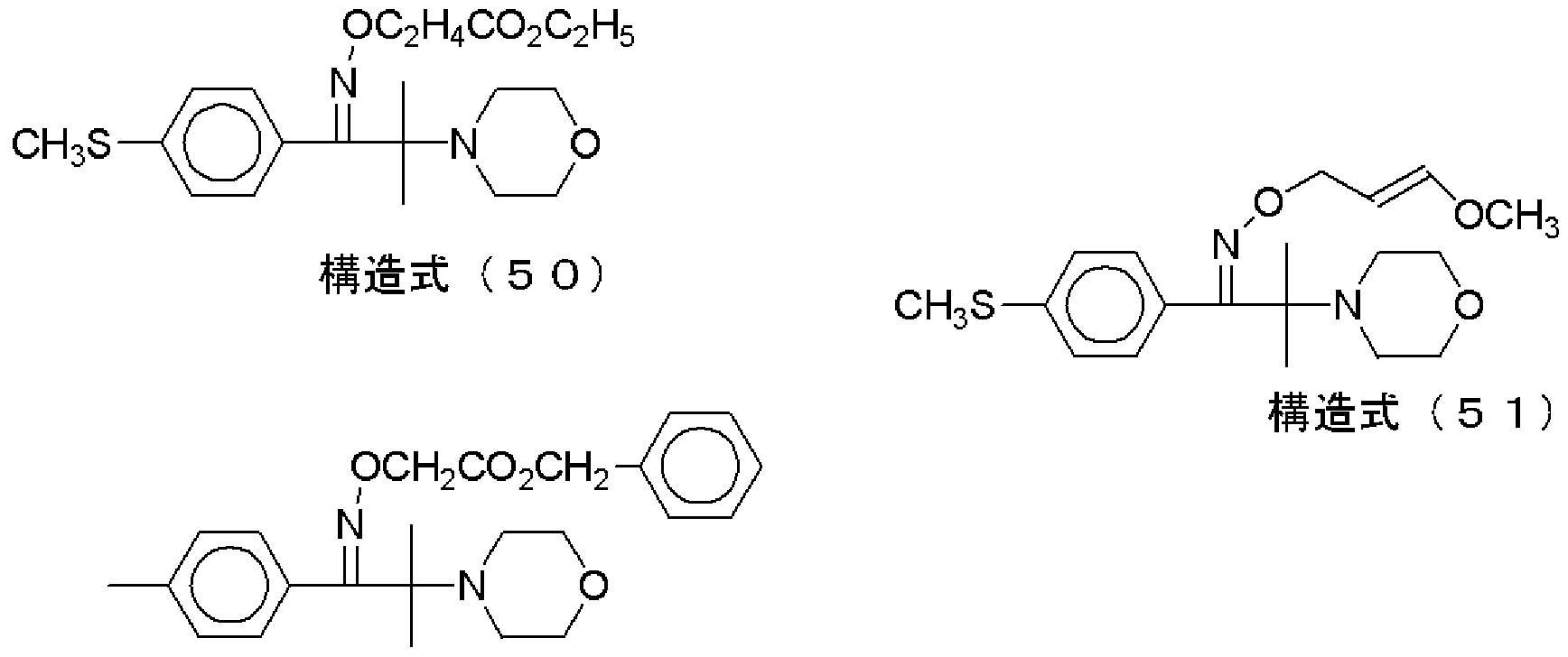
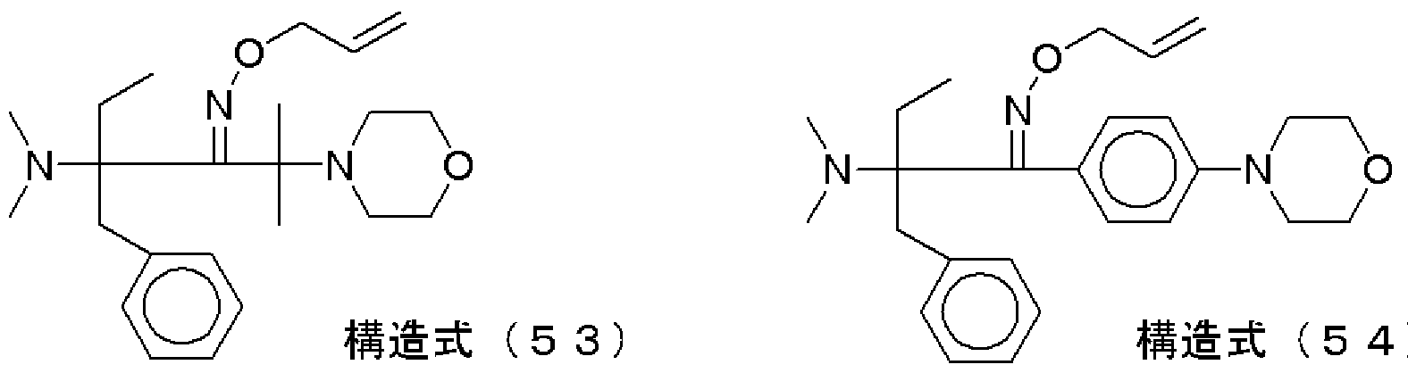
[0183] 本発明で好適に用いられるォキシム誘導体としては、例えば、下記構造式(39)〜(
72)で表される化合物が挙げられる。
[0184] [化 40]
Figure imgf000052_0001
Figure imgf000052_0002
Figure imgf000052_0003
構造式 (43) 構造式 (44)
Figure imgf000052_0004
構造式 (45) 構造式 (46
8)
Figure imgf000052_0005
構造式 (49)
[化 41]
Figure imgf000053_0001
Figure imgf000053_0002
Figure imgf000053_0003
Figure imgf000053_0004
構造式 (57)
[0186] [化 42]
Figure imgf000054_0001
Figure imgf000054_0002
Figure imgf000054_0003
Figure imgf000054_0004
)
[0187] [化 43]
Figure imgf000055_0001
R
構造式 (67) n-C3H7
構造式 (68) n-C8H17 構造式 (69) カンファー
構造式 (70) p-CH3C6H4
Figure imgf000055_0002
R
構造式 (7 1 ) n-C3H7 構造式 (72) p-CH3C6H4 前記ケトン化合物としては、例えば、ベンゾフエノン、 2 メチルベンゾフエノン、 3 メチルベンゾフエノン、 4 メチルベンゾフエノン、 4ーメトキシベンゾフエノン、 2 ク 口べンゾフエノン、 4 クロ口べンゾフエノン、 4 ブロモベンゾフエノン、 2—カノレボキ シベンゾフエノン、 2—エトキシカルボニルベンゾルフェノン、ベンゾフエノンテトラカル ボン酸又はそのテトラメチルエステル、 4, 4, 一ビス(ジアルキルァミノ)ベンゾフエノン 類(例えば、 4, 4, 一ビス(ジメチルァミノ)ベンゾフエノン、 4, 4, 一ビスジシクロへキシ ルァミノ)ベンゾフエノン、 4, 4, 一ビス(ジェチルァミノ)ベンゾフエノン、 4, 4, 一ビス( ジヒドロキシェチルァミノ)ベンゾフエノン、 4—メトキシ一 4 '—ジメチルァミノべンゾフエ ノン、 4, 4 '—ジメトキシベンゾフエノン、 4—ジメチルァミノべンゾフエノン、 4—ジメチ ルアミノアセトフエノン、ベンジル、アントラキノン、 2—t—ブチルアントラキノン、 2—メ チノレアントラキノン、フエナントラキノン、キサントン、チォキサントン、 2—クロノレーチォ キサントン、 2, 4 ジェチルチオキサントン、フルォレノン、 2 べンジルージメチルァ ミノー 1一 (4一モルホリノフエ-ル)一 1ーブタノン、 2—メチルー 1一 〔4一(メチルチオ )フエ-ル〕 2 モルホリノ一 1—プロパノン、 2 ヒドロキシー 2—メチルー〔4— ( 1— メチルビ-ル)フエ-ル〕プロパノールオリゴマー、ベンゾイン、ベンゾインエーテル類 (例えば、ベンゾインメチルエーテル、ベンゾインェチルエーテル、ベンゾインプロピ ノレエーテノレ、ベンゾインイソプロピノレエーテノレ、ベンゾインフエ-ノレエーテノレ、ベンジ ルジメチルケタール)、アタリドン、クロロアタリドン、 N—メチルアタリドン、 N ブチル アタリドン、 N ブチル一クロロアタリドンなどが挙げられる。
[0189] 前記メタ口セン類としては、例えば、ビス( 7? 5— 2, 4 シクロペンタジェン一 1—ィ ル)—ビス(2, 6 ジフロロ 3— ( 1H ピロール— 1—ィル)—フエ-ル)チタニウム 、 7? 5 シクロペンタジェ -ル一 6 タメ-ルーアイアン(1 + ) —へキサフロロホスフ エート(1 )、特開昭 53— 133428号公報、特公昭 57— 1819号公報、同 57— 609 6号公報及び米国特許第 3615455号明細書に記載された化合物などが挙げられる
[0190] また、上記以外の光重合開始剤として、アタリジン誘導体 (例えば、 9 フエ-ルァク リジン、 1 , 7 ビス(9、 9,—アタリジ-ル)ヘプタン等)、 N フエ-ルグリシン等、ポリ ハロゲン化合物(例えば、四臭化炭素、フエ-ルトリブ口モメチルスルホン、フエ-ルト リクロロメチルケトン等)、クマリン類(例えば、 3— (2—ベンゾフロイル)—7—ジェチ ルァミノクマリン、 3— (2 ベンゾフロイル) - 7 - ( 1—ピロリジ -ル)クマリン、 3 ベン ゾィル 7 ジェチルァミノクマリン、 3— (2—メトキシベンゾィル) 7 ジェチルアミ ノクマリン、 3—(4ージメチルァミノべンゾィル) 7—ジェチルァミノクマリン、 3,3,一 カルボ-ルビス(5, 7—ジ—n—プロポキシクマリン)、 3, 3,—カルボ-ルビス(7—ジ ェチルァミノクマリン)、 3—ベンゾィル 7—メトキシクマリン、 3— (2—フロイル) 7 ージェチルァミノクマリン、 3—(4ージェチルァミノシンナモイル) 7—ジェチルアミ ノクマリン、 7—メトキシ一 3— (3—ピリジルカルボ-ル)クマリン、 3—ベンゾィル 5, 7 —ジプロポキシクマリン、 7 ベンゾトリアゾール 2—イルクマリン、また、特開平 5-1 9475号公報、特開平 7- 271028号公報、特開 2002- 363206号公報、特開 2002 - 363207号公報、特開 2002 - 363208号公報、特開 2002 - 363209号公報等に記 載のクマリンィ匕合物など)、アミン類 (例えば、 4ージメチルァミノ安息香酸ェチル、 4 ジメチルァミノ安息香酸 n—ブチル、 4ージメチルァミノ安息香酸フエネチル、 4ージメ チルァミノ安息香酸 2 フタルイミドエチル、 4 ジメチルァミノ安息香酸 2—メタクリロ ィルォキシェチル、ペンタメチレンビス(4ージメチルァミノべンゾエート)、 3—ジメチ ルァミノ安息香酸のフエネチル、ペンタメチレンエステル、 4ージメチルァミノべンズァ ルデヒド、 2 クロルー4ージメチルァミノべンズアルデヒド、 4ージメチルァミノべンジ ルアルコール、ェチル(4ージメチルァミノべンゾィル)アセテート、 4ーピベリジノアセ トフエノン、 4—ジメチルァミノべンゾイン、 N, N ジメチルー 4—トルイジン、 N, N— ジェチルー 3—フエネチジン、トリベンジルァミン、ジベンジルフエニルァミン、 N—メ チル— N フエニルベンジルァミン、 4—ブロム— Ν,Ν ジメチルァニリン、トリドデシ ルァミン、ァミノフルオラン類(ODB, ODBII等)、クリスタルバイオレツトラクトン、ロイ コクリスタルバイオレット等)、ァシルホスフィンォキシド類 (例えば、ビス(2, 4, 6 トリ メチルベンゾィル)—フエ-ルホスフィンォキシド、ビス(2, 6 ジメトキシベンゾィル) - 2, 4, 4 トリメチルーペンチルフエ-ルホスフィンォキシド、 LucirinTPOなど)な どが挙げられる。
更に、米国特許第 2367660号明細書に記載されているビシナルポリケタルド-ル 化合物、米国特許第 2448828号明細書に記載されて 、るァシロインエーテルィ匕合 物、米国特許第 2722512号明細書に記載されている oc—炭化水素で置換された芳 香族ァシロインィ匕合物、米国特許第 3046127号明細書及び同第 2951758号明細 書に記載の多核キノンィ匕合物、特開 2002— 229194号公報に記載の有機ホウ素化 合物、ラジカル発生剤、トリアリールスルホ-ゥム塩 (例えば、へキサフロロアンチモン やへキサフロロホスフェートとの塩)、ホスホ-ゥム塩化合物(例えば、(フエ-ルチオ フエ-ル)ジフエ-ルスルホ-ゥム塩等)(カチオン重合開始剤として有効)、 WO01/ 71428号公報記載のォ-ゥム塩ィ匕合物などが挙げられる。
[0192] 前記光重合開始剤は、 1種単独で使用してもよぐ 2種以上を併用してもよい。 2種 以上の組合せとしては、例えば、米国特許第 3549367号明細書に記載のへキサァ リールビイミダゾールと 4 アミノケトン類との組合せ、特公昭 51—48516号公報に 記載のベンゾチアゾール化合物とトリハロメチルー s—トリァジン化合物の組合せ、ま た、芳香族ケトン化合物 (例えば、チォキサントン等)と水素供与体 (例えば、ジアルキ ルァミノ含有ィ匕合物、フエノール化合物等)の組合せ、へキサァリールビイミダゾール とチタノセンとの組合せ、クマリン類とチタノセンとフエ-ルグリシン類との組合せなど が挙げられる。
[0193] 前記感光層における光重合開始剤の含有量としては、 0. 1〜30質量%が好ましく 、0. 5〜20質量%がより好ましぐ 0. 5〜15質量%が特に好ましい。
[0194] ——その他の成分——
前記その他の成分としては、例えば、増感剤、熱重合禁止剤、可塑剤、発色剤、着 色剤などが挙げられ、更に基体表面への密着促進剤及びその他の助剤類 (例えば、 顔料、導電性粒子、充填剤、消泡剤、難燃剤、レべリング剤、剥離促進剤、酸化防止 剤、香料、熱架橋剤、表面張力調整剤、連鎖移動剤等)を併用してもよい。これらの 成分を適宜含有させることにより、 目的とするパターン形成材料の安定性、写真性、 焼きだし性、膜物性等の性質を調整することができる。
[0195] 増感剤
前記増感剤は、後述する光照射手段として可視光線や紫外光'可視光レーザなど により適宜選択することができる。
前記増感剤は、活性エネルギー線により励起状態となり、他の物質 (例えば、ラジカ ル発生剤、酸発生剤等)と相互作用(例えば、エネルギー移動、電子移動等)するこ とにより、ラジカルや酸等の有用基を発生することが可能である。 [0196] 前記増感剤としては、特に制限はなぐ公知の増感剤の中から適宜選択することが でき、例えば、公知の多核芳香族類 (例えば、ピレン、ペリレン、トリフエ-レン)、キサ ンテン類(例えば、フルォレセイン、ェォシン、エリス口シン、ローダミン B、ローズベン ガル)、シァニン類(例えば、インドカルボシァニン、チアカルボシァニン、ォキサカル ボシァニン)、メロシアニン類(例えば、メロシアニン、カルボメロシアニン)、チアジン 類(例えば、チォニン、メチレンブルー、トルイジンブルー)、アタリジン類(例えば、ァ クリジンオレンジ、クロロフラビン、ァクリフラビン)、アントラキノン類 (例えば、アントラ キノン)、スクァリウム類 (例えば、スクァリウム)、アタリドン類 (例えば、アタリドン、クロ ロアタリドン、 N—メチルアタリドン、 N ブチルアタリドン、 N ブチル一クロロアクリド ン等)、クマリン類(例えば、 3—(2 べンゾフロイル) 7 ジェチルァミノクマリン、 3 - (2 ベンゾフロイル) 7— (1—ピロリジ -ル)クマリン、 3 ベンゾィル 7 ジェ チルァミノクマリン、 3- (2—メトキシベンゾィル) 7 ジェチルァミノクマリン、 3— (4 —ジメチルァミノべンゾィル) 7—ジェチルァミノクマリン、 3,3,一カルボニルビス(5 , 7—ジ n—プロポキシクマリン)、 3, 3,一カルボニルビス(7—ジェチルァミノタマリ ン)、 3—ベンゾィル 7—メトキシクマリン、 3— (2—フロイル) 7—ジェチルアミノク マリン、 3—(4ージェチルァミノシンナモイル) 7—ジェチルァミノクマリン、 7—メトキ シ— 3— (3—ピリジルカルボ-ル)クマリン、 3—ベンゾィル—5, 7—ジプロポキシクマ リン等があげられる。他には、特開平 5-19475号公報、特開平 7-271028号公報、 特開 2002 - 363206号公報、特開 2002 - 363207号公報、特開 2002 - 363208号 公報、特開 2002-363209号公報等に記載のクマリン化合物など)も挙げられる。
[0197] 前記光重合開始剤と前記増感剤との組合せとしては、例えば、特開 2001 - 3057 34号公報に記載の電子移動型開始系 [ (1)電子供与型開始剤及び増感色素、 (2) 電子受容型開始剤及び増感色素、(3)電子供与型開始剤、増感色素及び電子受容 型開始剤 (三元開始系)]などの組合せが挙げられる。
[0198] 前記増感剤の含有量としては、特に制限はなぐ目的に応じて適宜選択することが でき、感光性榭脂組成物の全成分に対し、 0. 05〜30質量%が好ましぐ 0. 1〜20 質量%がより好ましぐ 0. 2〜10質量%が特に好ましい。
前記含有量が、 0. 05質量%未満となると、活性エネルギー線への感度が低下し、 露光プロセスに時間がかかり、生産性が低下することがあり、 30質量%を超えると、 前記感光層から保存時に析出することがある。
[0199] 熱重合禁止剤
前記熱重合禁止剤は、前記感光層における前記重合性化合物の熱的な重合又は 経時的な重合を防止するために添加してもよ 、。
前記熱重合禁止剤としては、例えば、 4—メトキシフエノール、ハイドロキノン、アル キルまたはァリール置換ノヽイドロキノン、 tーブチルカテコール、ピロガロール、 2—ヒド ロキシベンゾフエノン、 4—メトキシ一 2 ヒドロキシベンゾフエノン、塩化第一銅、フエ ノチアジン、クロラニル、ナフチルァミン、 13 ナフトール、 2, 6 ジ tーブチルー 4 クレゾール、 2, 2,ーメチレンビス(4ーメチルー 6 t—ブチルフエノール)、ピリジン 、ニトロベンゼン、ジニトロベンゼン、ピクリン酸、 4ートルイジン、メチレンブルー、銅と 有機キレート剤反応物、サリチル酸メチル、フエノチアジン、ニトロソィ匕合物及び-トロ ソ化合物と A1とのキレート等が挙げられる。
[0200] 前記熱重合禁止剤の含有量としては、前記感光層の前記重合性化合物に対して 0 . 001〜5質量%が好ましぐ 0. 005〜2質量%がより好ましぐ 0. 01〜1質量%が 特に好ましい。
前記含有量が、 0. 001質量%未満であると、保存時の安定性が低下することがあ り、 5質量%を超えると、活性エネルギー線に対する感度が低下することがある。
[0201] 可塑剤
前記可塑剤は、前記感光層の膜物性 (可撓性)をコントロールするために添加して ちょい。
前記可塑剤としては、例えば、ジメチルフタレート、ジブチルフタレート、ジイソプチ ルフタレート、ジヘプチルフタレート、ジォクチルフタレート、ジシクロへキシルフタレ ート、ジトリデシルフタレート、ブチルベンジルフタレート、ジイソデシルフタレート、ジ フエ-ルフタレート、ジァリルフタレート、ォクチルカプリールフタレート等のフタル酸ェ ステル類;トリエチレングリコールジアセテート、テトラエチレングリコールジアセテート 、ジメチルダリコースフタレート、ェチノレフタリーノレエチノレグリコレート、メチルフタリー ルェチルダリコレート、ブチノレフタリーノレブチノレグリコレート、トリエチレングリコールジ カブリル酸エステル等のグリコールエステル類;トリクレジルホスフェート、トリフエ-ル ホスフェート等のリン酸エステル類; 4 トルエンスルホンアミド、ベンゼンスルホンアミ ド、 N—n—ブチルベンゼンスルホンアミド、 N—n—ブチルァセトアミド等のアミド類; ジイソブチルアジペート、ジォクチルアジペート、ジメチルセバケート、ジブチルセパ ケート、ジォクチルセパケート、ジォクチルァゼレート、ジブチルマレート等の脂肪族 二塩基酸エステル類;タエン酸トリエチル、タエン酸トリブチル、グリセリントリァセチル エステル、ラウリン酸ブチル、 4, 5 ジエポキシシクロへキサン 1, 2 ジカルボン酸 ジォクチル等、ポリエチレングリコール、ポリプロピレングリコール等のダリコール類が 挙げられる。
[0202] 前記可塑剤の含有量としては、前記感光層の全成分に対して 0. 1〜50質量%が 好ましく、 0. 5〜40質量%がより好ましぐ 1〜30質量%が特に好ましい。
[0203] 発色剤
前記発色剤は、露光後の前記感光層に可視像を与える (焼きだし機能)ために添 カロしてちょい。
前記発色剤としては、例えば、トリス (4—ジメチルァミノフエ-ル)メタン (ロイコクリス タルバイオレット)、トリス(4—ジェチルァミノフエ-ル)メタン、トリス(4—ジメチルァミノ - 2 メチルフエ-ル)メタン、トリス(4 -ジェチルァミノ 2 メチルフエ-ル)メタン、 ビス(4 ジブチルァミノフエ-ル)一〔4一(2 シァノエチル)メチルァミノフエ-ル〕メ タン、ビス(4 ジメチルァミノフエ-ル) 2 キノリルメタン、トリス(4 ジプロピルアミ ノフエ-ル)メタン等のアミノトリアリールメタン類; 3, 6—ビス(ジメチルァミノ) 9—フ ェ -ルキサンチン、 3—ァミノ 6 ジメチルァミノ一 2—メチル 9— (2 クロ口フエ二 ル)キサンチン等のアミノキサンチン類; 3, 6 ビス(ジェチルァミノ) 9 (2 ェトキ シカルボ-ルフエ-ル)チォキサンテン、 3, 6—ビス(ジメチルァミノ)チォキサンテン 等のアミノチォキサンテン類; 3, 6 ビス(ジェチルァミノ) 9, 10 ジヒドロー 9ーフ ェ-ルアタリジン、 3, 6 ビス(ベンジルァミノ)一 9, 10 ジビドロ一 9—メチルアタリ ジン等のアミノー 9, 10 ジヒドロアクリジン類; 3, 7 ビス(ジェチルァミノ)フエノキサ ジン等のアミノフエノキサジン類; 3, 7—ビス(ェチルァミノ)フエノチアゾン等のアミノフ エノチアジン類; 3, 7 ビス(ジェチルァミノ) 5 へキシルー 5, 10 ジヒドロフエナ ジン等のアミノジヒドロフエナジン類;ビス(4 -ジメチルァミノフエ-ル)ァ-リノメタン等 のァミノフエ-ルメタン類; 4 アミノー 4'ージメチルアミノジフエ-ルァミン、 4ーァミノ α、 j8—ジシァノヒドロケィ皮酸メチルエステル等のアミノヒドロケィ皮酸類; 1一(2 ナフチル) 2 フエ-ルヒドラジン等のヒドラジン類; 1 , 4 ビス(ェチルァミノ) 2 , 3 ジヒドロアントラキノン類のアミノ一 2, 3 ジヒドロアントラキノン類; N, N ジェ チル 4 フエネチルァ-リン等のフエネチルァ-リン類; 10 ァセチル 3, 7 ビ ス(ジメチルァミノ)フエノチアジン等の塩基性 NHを含むロイコ色素のァシル誘導体; トリス(4 ジェチルァミノ 2 トリル)エトキシカルボ-ルメンタン等の酸化しうる水素 を有して!/、な 、が、発色化合物に酸ィ匕しうるロイコ様ィ匕合物;ロイコインジゴイド色素; 米国特許 3, 042, 515号及び同第 3, 042, 517号に記載されているような発色形に 酸化しうるような有機アミン類(例、 4, 4,一エチレンジァミン、ジフエ-ルァミン、 N, N ジメチルァニリン、 4, 4'ーメチレンジァミントリフエニルァミン、 N ビニルカルバゾ ール)が挙げられ、これらの中でも、ロイコクリスタルバイオレット等のトリアリールメタン 系化合物が好ましい。
更に、前記発色剤は、前記ロイコ体を発色させるためなどの目的で、ハロゲンィ匕合 物と組み合わせることが一般に知られて 、る。
前記ハロゲン化合物としては、例えば、ハロゲン化炭化水素(例えば、四臭化炭素 、ョードホルム、臭化工チレン、臭ィ匕メチレン、臭化ァミル、臭ィ匕イソァミル、ヨウィ匕アミ ル、臭化イソブチレン、ヨウ化ブチル、臭化ジフエ-ルメチル、へキサクロロェタン、 1, 2—ジブロモェタン、 1, 1, 2, 2—テトラブロモェタン、 1, 2—ジブ口モー 1, 1, 2—ト リクロロエタン、 1, 2, 3トリブロモプロノくン、 1—ブロモ 4 クロロブタン、 1, 2, 3, 4 ーテトラブロモブタン、テトラクロロシクロプロペン、へキサクロロシクロペンタジェン、ジ ブロモシキロへキサン、 1, 1, 1—トリクロ口一 2, 2 ビス(4 クロ口フエ-ル)ェタンな ど);ハロゲン化アルコール化合物(例えば、 2, 2, 2—トリクロ口エタノール、トリブロモ エタノーノレ、 1, 3 ジクロロ一 2 プロパノーノレ、 1, 1, 1—トリクロ口一 2 プロパノー ル、ジ(ョードへキサメチレン)ァミノイソプロパノール、トリブロモー t—ブチルアルコー ル、 2, 2, 3 トリクロロブタン 1, 4ージオールなど);ハロゲン化カルボ-ル化合物 (例えば 1, 1ージクロ口アセトン、 1, 3 ジクロ口アセトン、へキサクロ口アセトン、へキ サブロモアセトン、 1, 1, 3, 3—テトラクロ口アセトン、 1, 1, 1 トリクロ口アセトン、 3, 4 ジブ口モー 2 ブタノン、 1, 4ージクロロー 2 ブタノン ジブ口モシクロへキサノ ン等);ハロゲン化エーテル化合物(例えば 2—ブロモェチルメチルエーテル、 2—ブ ロモェチノレエチノレエーテノレ、ジ (2—ブロモェチノレ)エーテノレ、 1, 2—ジクロロェチノレ ェチルエーテル等);ハロゲン化エステル化合物(例えば、酢酸ブロモェチル、トリクロ 口酢酸ェチル、トリクロ口酢酸トリクロロェチル、 2, 3 ジブロモプロピルアタリレートの ホモポリマー及び共重合体、ジブロモプロピオン酸トリクロロェチル、 a , j8—ジグロ 口アクリル酸ェチル等);ハロゲン化アミド化合物(例えば、クロロアセトアミド、ブロモア セトアミド、ジクロロアセトアミド、トリクロロアセトアミド、トリブロモアセトアミド、トリクロ口 ェチルトリクロロアセトアミド、 2—ブロモイソプロピオンアミド、 2, 2, 2—トリクロ口プロ ピオンアミド、 N クロロスクシンイミド、 N—ブロモスクシンイミドなど);硫黄やリンを有 する化合物(例えば、トリブロモメチルフエ-ルスルホン、 4 -トロフエ-ルトリブロモ メチルスルホン、 4 クロルフエニルトリブ口モメチルスルホン、トリス(2, 3 ジブロモ プロピル)ホスフェート等)、 2, 4 ビス(トリクロロメチル) 6 フエ-ルトリアゾールなど が挙げられる。有機ハロゲンィ匕合物では、同一炭素原子に結合した 2個以上のハロ ゲン原子を持つハロゲンィ匕合物が好ましぐ 1個の炭素原子に 3個のハロゲン原子を 持つハロゲンィ匕合物がより好ましい。前記有機ハロゲン化合物は、 1種単独で使用し てもよく、 2種以上を併用してもよい。これらの中でも、トリブロモメチルフエ-ルスルホ ン、 2, 4 ビス(トリクロロメチル) 6 フエ-ルトリアゾールが好ましい。
[0205] 前記発色剤の含有量としては、前記感光層の全成分に対して 0. 01〜20質量%が 好ましぐ 0. 05〜10質量%がより好ましぐ 0. 1〜5質量%が特に好ましい。また、 前記ハロゲンィ匕合物の含有量としては、前記感光層の全成分に対し 0. 001〜5質 量%が好ましぐ 0. 005〜1質量%がより好ましい。
[0206] 染料
前記感光層には、取り扱い性の向上のために感光性榭脂組成物を着色し、又は保 存安定性を付与する目的に、染料を用いることができる。
前記染料としては、ブリリアントグリーン (例えば、その硫酸塩)、ェォシン、ェチルバ ィォレット、エリス口シン B、メチルグリーン、クリスタルバイオレット、べィシックフクシン 、フエノールフタレイン、 1, 3 ジフエニルトリアジン、ァリザリンレッド S、チモールフタ レイン、メチルバイオレット 2B、キナルジンレッド、ローズベンガル、メタ-ルーイエロ 一、チモールスルホフタレイン、キシレノールブルー、メチルオレンジ、オレンジ IV、ジ フエニルチロカルバゾン、 2, 7 ジクロ口フルォレセイン、パラメチルレッド、コンゴ一 レッド、ベンゾプルプリン 4B、 a ナフチルーレッド、ナイルブルー A、フエナセタリン 、メチルバイオレット、マラカイトグリーン、パラフクシン、オイルブルー # 603 (オリエン ト化学工業社製)、ローダミン B、ロータミン 6G、ビクトリアピュアブルー BOHなどを挙 げることができ、これらの中でもカチオン染料 (例えば、マラカイトグリーンシユウ酸塩、 マラカイトグリーン硫酸塩等)が好ましい。該カチオン染料の対ァ-オンとしては、有 機酸又は無機酸の残基であればよぐ例えば、臭素酸、ヨウ素酸、硫酸、リン酸、シュ ゥ酸、メタンスルホン酸、トルエンスルホン酸等の残基(ァ-オン)などが挙げられる。
[0207] 前記染料の含有量としては、前記感光層の全成分に対して 0. 001〜10質量%が 好ましぐ 0. 01〜5質量%がより好ましぐ 0. 1〜2質量%が特に好ましい。
[0208] 密着促進剤
各層間の密着性、又はパターン形成材料と基体との密着性を向上させるために、 各層に公知の 、わゆる密着促進剤を用いることができる。
[0209] 前記密着促進剤としては、例えば、特開平 5— 11439号公報、特開平 5— 34153 2号公報及び特開平 6—43638号公報等に記載の密着促進剤が好適挙げられる。 具体的には、ベンズイミダゾール、ベンズォキサゾール、ベンズチアゾール、 2—メル カプトべンズイミダゾール、 2—メルカプトべンズォキサゾール、 2—メルカプトべンズ チアゾール、 3 モルホリノメチルー 1 フエ二ルートリアゾールー 2 チオン、 3 モ ルホリノメチル 5 フエニル ォキサジァゾール 2 チオン、 5 アミノー 3 モル ホリノメチル チアジアゾール 2 チオン、 2 メルカプト 5—メチルチオ チアジ ァゾール、トリァゾール、テトラゾール、ベンゾトリァゾール、カルボキシベンゾトリァゾ ール、アミノ基含有べンゾトリアゾール及びシランカップリング剤などが挙げられる。
[0210] 前記密着促進剤の含有量としては、前記感光層の全成分に対して 0. 001質量% 〜20質量%が好ましぐ 0. 01〜10質量%がより好ましぐ 0. 1質量%〜5質量%が 特に好ましい。 [0211] 前記感光層は、例えば、 J.コーサ一著「ライトセンシティブシステムズ」第 5章に記 載されているような有機硫黄ィ匕合物、過酸化物、レドックス系化合物、ァゾ又はジァゾ 化合物、光還元性色素、有機ハロゲンィ匕合物などを含んでいてもよい。
[0212] 前記有機硫黄ィ匕合物としては、例えば、ジー n—ブチルジサルファイド、ジベンジル ジサルファイド、 2—メルカプロべンズチアゾール、 2—メルカプトべンズォキサゾール 、チォフエノール、ェチルトリクロロメタンスルフエネート、 2—メルカプトべンズイミダゾ ールなどが挙げられる。
[0213] 前記過酸化物としては、例えば、ジー t ブチルパーオキサイド、過酸化ベンゾィル 、メチルェチルケトンパーオキサイドを挙げることができる。
[0214] 前記レドックス化合物は、過酸ィ匕物と還元剤の組合せ力もなるものであり、第一鉄ィ オンと過硫酸イオン、第二鉄イオンと過酸ィ匕物などを挙げることができる。
[0215] 前記ァゾ及びジァゾィ匕合物としては、例えば、 α , α '—ァゾビスイリブチ口-トリル 、 2 ァゾビス一 2—メチルブチ口-トリル、 4 アミノジフエニルァミンのジァゾニゥム 類が挙げられる。
[0216] 前記光還元性色素としては、例えば、ローズベンガル、エリス口シン、ェォシン、ァク リフラビン、リボフラビン、チォニンが挙げられる。
[0217] ——界面活性剤——
本発明の前記パターン形成材料を製造する際に発生する面状ムラを改善させるた めに、公知の界面活性剤を添加することができる。
前記界面活性剤としては、例えば、ァニオン系界面活性剤、カチオン系界面活性 剤、ノ-オン系界面活性剤、両性界面活性剤、フッ素含有界面活性剤などから適宜 選択できる。
[0218] 前記界面活性剤の含有量としては、感光性榭脂組成物の固形分に対し、 0. 001
〜 10質量%が好ましい。
前記含有量が、 0. 001質量%未満になると、面状改良の効果が得られなくことがあ り、 10質量%を超えると、密着性が低下することがある。
[0219] 前記界面活性剤としては、上述の界面活性剤の他、フッ素系の界面活性剤として、 炭素鎖 3〜20でフッ素原子を 40質量%以上含み、かつ、非結合末端から数えて少 なくとも 3個の炭素原子に結合した水素原子がフッ素置換されているフルォロ脂肪族 基を有するアタリレート又はメタタリレートを共重合成分として有する高分子界面活性 剤も好適に挙げられる。
[0220] 前記感光層の厚みとしては、特に制限はなぐ 目的に応じて適宜選択することがで き、 ί列免ば、、 1〜: LOO μ m力 S好ましく、 2〜50 μ m力 Sより好ましく、 4〜30 μ m力 S特に好 ましい。
[0221] ——その他の層——
前記その他の層としては、特に制限はなぐ 目的に応じて適宜選択することができ、 例えば、クッション層、バリア層、剥離層、接着層、光吸収層、表面保護層等の層が 挙げられる。前記パターン形成材料は、これらの層を 1種単独で有していてもよぐ 2 種以上を有していてもよい。また、同種の層を 2層以上有していてもよい。
[0222] ——保護フィルム——
前記パターン形成材料は、前記感光層上に保護フィルムを形成してもよ 、。
前記保護フィルムとしては、例えば、前記支持体に使用されるもの、紙、ポリエチレ ン、ポリプロピレン力ラミネートされた紙、などが挙げられ、これらの中でも、ポリエチレ ンフィルム、ポリプロピレンフィルムが好ましい。
前記保護フィルムの厚みとしては、特に制限はなぐ 目的に応じて適宜選択するこ と力 Sでき、 ί列えば、、 5〜: LOO μ m力 S好ましく、 8〜50 μ m力 Sより好ましく、 10〜30 μ m が特に好ましい。
前記保護フィルムを用いる場合、前記感光層及び前記支持体の接着力 Aと、前記 感光層及び保護フィルムの接着力 Bとが、接着力 A>接着力 Bの関係であることが好 ましい。
前記支持体と保護フィルムとの組合せ (支持体 Z保護フィルム)としては、例えば、 ポリエチレンテレフタレート zポリプロピレン、ポリエチレンテレフタレート zポリエチレ ン、ポリ塩化ビュル Zセロファン、ポリイミド Zポリプロピレン、ポリエチレンテレフタレ ート zポリエチレンテレフタレートなどが挙げられる。また、支持体及び保護フィルム の少なくとも 、ずれかを表面処理することにより、上述のような接着力の関係を満たす ことができる。前記支持体の表面処理は、前記感光層との接着力を高めるために施 されてもよぐ例えば、下塗層の塗設、コロナ放電処理、火炎処理、紫外線照射処理 、高周波照射処理、グロ一放電照射処理、活性プラズマ照射処理、レーザ光線照射 処理などを挙げることができる。
[0223] また、前記支持体と前記保護フィルムとの静摩擦係数としては、 0. 3〜1. 4が好ま しく、 0. 5〜1. 2力より好まし!/ヽ。
前記静摩擦係数が、 0. 3未満であると、滑り過ぎるため、ロール状にした場合に卷 ズレが発生することがあり、 1. 4を超えると、良好なロール状に巻くことが困難となるこ とがある。
前記摩擦係数の測定方法としては、特に制限はなぐ目的に応じて適宜選択するこ と力 sでき、 ί列えば、、 JIS Κ 7125に基づ!/、て、対 SUS304、面圧 0. 005MPaなどの 条件での測定などが挙げられる。
[0224] 前記パターン形成材料は、例えば、円筒状の卷芯に巻き取って、長尺状でロール 状に巻かれて保管されることが好ましい。前記長尺状のパターン形成材料の長さとし ては、特に制限はなぐ例えば、 10m〜20, OOOmの範囲力 適宜選択することがで きる。また、ユーザーが使いやすいようにスリット加工し、 100m〜l, OOOmの範囲の 長尺体をロール状にしてもよい。なお、この場合には、前記支持体が一番外側になる ように巻き取られることが好ましい。また、前記ロール状のパターン形成材料をシート 状にスリットしてもよい。保管の際、端面の保護、エッジフュージョンを防止する観点か ら、端面にはセパレーター (特に防湿性のもの、乾燥剤入りのもの)を設置することが 好ましぐまた梱包も透湿性の低 、素材を用いることが好ま 、。
[0225] 前記保護フィルムは、前記保護フィルムと前記感光層との接着性を調整するために 表面処理してもよい。前記表面処理は、例えば、前記保護フィルムの表面に、ポリオ ルガノシロキサン、弗素化ポリオレフイン、ポリフルォロエチレン、ポリビュルアルコー ル等のポリマーからなる下塗層を形成させる。該下塗層の形成は、前記ポリマーの塗 布液を前記保護フィルムの表面に塗布した後、 30〜150°C (特に 50〜120°C)で 1 〜30分間乾燥させることにより形成させることができる。
[0226] パターン形成材料の製造方法
前記パターン形成材料は、例えば、次のようにして製造することができる。 まず、上述の各種材料を、水又は溶剤に溶解、乳化又は分散させて感光性榭脂組 成物溶液を調製する。
[0227] 前記感光性榭脂組成物溶液の溶剤としては、特に制限はなぐ 目的に応じて適宜 選択することができ、例えば、メタノール、エタノール、 n プロパノール、イソプロパノ ール、 n—ブタノール、 sec ブタノール、 n—へキサノール等のアルコール類;ァセト ン、メチルェチルケトン、メチルイソブチルケトン、シクロへキサノン、ジイソプチルケト ンなどのケトン類;酢酸ェチル、酢酸ブチル、酢酸 n—ァミル、硫酸メチル、プロピ オン酸ェチル、フタル酸ジメチル、安息香酸ェチル及びメトキシプロピルアセテートな どのエステル類;トルエン、キシレン、ベンゼン、ェチルベンゼンなどの芳香族炭化水 素類;四塩ィ匕炭素、トリクロロエチレン、クロ口ホルム、 1, 1, 1—トリクロロェタン、塩ィ匕 メチレン、モノクロ口ベンゼンなどのハロゲン化炭化水素類;テトラヒドロフラン、ジェチ ノレエーテノレ、エチレングリコーノレモノメチノレエーテノレ、エチレングリコーノレモノェチノレ エーテル、 1ーメトキシー2—プロパノールなどのエーテル類;ジメチルホルムアミド、 ジメチルァセトアミド、ジメチルスルホオキサイド、スルホランなどが挙げられる。これら は、 1種単独で使用してもよぐ 2種以上を併用してもよい。また、公知の界面活性剤 を添加してもよい。
[0228] 次に、前記感光性榭脂組成物溶液を支持体上に塗布し、乾燥させることにより感光 層を形成し、パターン形成材料を製造することができる。
前記感光性榭脂組成物溶液の塗布方法としては、特に制限はなぐ 目的に応じて 適宜選択することができ、例えば、スプレー法、ロールコート法、回転塗布法、スリット コート法、エタストルージョンコート法、カーテンコート法、ダイコート法、グラビアコート 法、ワイヤーバーコート法、ナイフコート法等の各種の塗布方法が挙げられる。
前記乾燥の条件としては、各成分、溶媒の種類、使用割合等によっても異なるが、 通常 60〜 110°Cの温度で 30秒間〜 15分間程度である。
[0229] ——積層体——
前記露光の対象としては、感光層を有する前記パターン形成材料である限り、特に 制限はなぐ 目的に応じて適宜選択することができ、例えば、基体上に前記パターン 形成材料を形成してなる積層体に対して行われることが好ましい。 [0230] 基体
前記基体としては、特に制限はなぐ公知の材料の中から表面平滑性の高いもの 力も凸凹のある表面を有するものまで適宜選択することができ、板状の基体 (基板)が 好ましぐ具体的には、公知のプリント配線板形成用基板 (例えば、銅張積層板)、ガ ラス板 (例えば、ソーダガラス板等)、合成樹脂性のフィルム、紙、金属板などが挙げ られる。
[0231] 前記基体は、該基体上に前記パターン形成材料における感光層が重なるようにし て積層してなる積層体を形成して用いることができる。即ち、前記積層体におけるパ ターン形成材料の前記感光層に対して露光することにより、露光した領域を硬化させ 、後述する現像工程によりパターンを形成することができる。
[0232] 前記パターン形成材料は、プリント配線板、カラーフィルタや柱材、リブ材、スぺー サー、隔壁などのディスプレイ用部材、ホログラム、マイクロマシン、プルーフなどのパ ターン形成用として広く用いることができ、特に本発明のパターン形成方法及びバタ ーン形成装置に好適に用いることができる。
[0233] パターン形成装置、パターン形成方法
本発明のパターン形成方法は、露光工程を少なくとも含み、適宜選択したその他の 工程を含む。
[0234] ——露光工程——
前記露光工程は、支持体上に感光層を有するパターン形成材料における該感光 層に対し、光照射手段からの光を受光し出射する描素部を n個有する光変調手段に より、前記光照射手段からの光を変調させた後、前記描素部における出射面の歪み による収差を補正可能な非球面を有するマイクロレンズを配列したマイクロレンズァレ ィを通して露光を行う工程である。
[0235] 変調手段——
前記光変調手段としては、 n個の描素部を有する限り、特に制限はなぐ目的に応 じて適宜選択することができ、例えば、空間光変調素子等が好適に挙げられる。 前記空間光変調素子としては、例えば、デジタル ·マイクロミラー ·デバイス (DMD) 、 MEMS (Micro Electro Mechanical Systems)タイプの空間光変調素子(S LM ; Special Light Modulator)、電気光学効果により透過光を変調する光学素 子(PLZT素子)、液晶光シャツタ(FLC)などが挙げられ、これらの中でも DMDが好 適に挙げられる。
[0236] 以下、前記光変調手段の一例について図面を参照しながら説明する。
DMD50は図 2に示すように、 SRAMセル (メモリセル) 60上〖こ、各々描素(ピクセ ル)を構成する多数 (例えば、 1024個 X 768個)の微小ミラー(マイクロミラー) 62が 格子状に配列されてなるミラーデバイスである。各ピクセルにおいて、最上部には支 柱に支えられたマイクロミラー 62が設けられており、マイクロミラー 62の表面にはアル ミニゥム等の反射率の高い材料が蒸着されている。なお、マイクロミラー 62の反射率 は 90%以上であり、その配列ピッチは縦方向、横方向とも一例として 13. であ る。また、マイクロミラー 62の直下には、ヒンジおよびヨークを含む支柱を介して通常 の半導体メモリの製造ラインで製造されるシリコンゲートの CMOSの SRAMセル 60 が配置されており、全体はモノリシックに構成されている。
[0237] DMD50の SRAMセル 60にデジタル信号が書き込まれると、支柱に支えられたマ イク口ミラー 62が、対角線を中心として DMD50が配置された基板側に対して ±ひ度 (例えば ± 12度)の範囲で傾けられる。図 3Aは、マイクロミラー 62がオン状態である + α度に傾いた状態を示し、図 3Βは、マイクロミラー 62がオフ状態である α度に 傾いた状態を示す。したがって、パターン情報に応じて、 DMD50の各ピクセルにお けるマイクロミラー 62の傾きを、図 2に示すように制御することによって、 DMD50に入 射したレーザ光 Βはそれぞれのマイクロミラー 62の傾き方向へ反射される。
[0238] なお、図 2には、 DMD50の一部を拡大し、マイクロミラー 62が + α度又は α度 に制御されて ヽる状態の一例を示す。それぞれのマイクロミラー 62のオンオフ制御は 、 DMD50に接続されたコントローラ 302 (図 13参照)によって行われる。また、オフ 状態のマイクロミラー 62で反射したレーザ光 Βが進行する方向には、光吸収体(図示 せず)が配置されている。
[0239] また、 DMD50は、その短辺が副走査方向と所定角度 Θ (例えば、 0. 1° 〜5° ) を成すように僅かに傾斜させて配置するのが好まし 、。図 4Αは DMD50を傾斜させ ない場合の各マイクロミラーによる反射光像 (露光ビーム) 53の走査軌跡を示し、図 4 Bは DMD50を傾斜させた場合の露光ビーム 53の走査軌跡を示している。
[0240] DMD50には、長手方向にマイクロミラーが多数個(例えば、 1024個)配列された マイクロミラー列力 短手方向に多数^ 1_ (例えば、 756糸且)配列されている力 図 4Bに 示すように、 DMD50を傾斜させることにより、各マイクロミラーによる露光ビーム 53の 走査軌跡(走査線)のピッチ P 1S DMD50を傾斜させない場合の走査線のピッチ P
1 2 より狭くなり、解像度を大幅に向上させることができる。一方、 DMD50の傾斜角は微 小であるので、 DMD50を傾斜させた場合の走査幅 Wと、 DMD50を傾斜させない
2
場合の走査幅 wとは略同一である。
[0241] 次に、前記光変調手段における変調速度を速くさせる方法 (以下「高速変調」と称 する)について説明する。
前記光変調手段は、前記 n個の描素の中から連続的に配置された任意の n個未満 の前記描素部をパターン情報に応じて制御可能であることが好まし 、。前記光変調 手段のデータ処理速度には限界があり、使用する描素数に比例して 1ライン当りの変 調速度が決定されるので、連続的に配列された任意の n個未満の描素部だけを使用 することで 1ライン当りの変調速度が速くなる。
[0242] 以下、前記高速変調について図面を参照しながら更に説明する。
ファイバアレイ光源 66から DMD50にレーザ光 Bが照射されると、 DMD50のマイク 口ミラーがオン状態のときに反射されたレーザ光は、レンズ系 54、 58によりパターン 形成材料 150上に結像される(図 12参照)。このようにして、ファイバアレイ光源 66か ら出射されたレーザ光が描素毎にオンオフされて、パターン形成材料 150が DMD5 0の使用描素数と略同数の描素単位 (露光エリア 168)で露光される(図 11及び図 1 2参照)。また、パターン形成材料 150がステージ 152と共に一定速度で移動される ことにより、パターン形成材料 150がスキャナ 162によりステージ移動方向と反対の方 向に副走査され、露光ヘッド 166毎に帯状の露光済み領域 170が形成される(図 8 及び図 9参照)。
[0243] なお本例では、図 5A及び図 5Bに示すように、 DMD50には、主走査方向にマイク 口ミラーが 1024個配列されたマイクロミラー列が副走査方向に 768組配列されてい る力 本例では、前記コントローラ 302 (図 13参照)により一部のマイクロミラー列(例 えば、 1024個 X 256列)だけが駆動するように制御がなされる。
[0244] この場合、図 5Aに示すように DMD50の中央部に配置されたマイクロミラー列を使 用してもよぐ図 5Bに示すように、 DMD50の端部に配置されたマイクロミラー列を使 用してもよい。また、一部のマイクロミラーに欠陥が発生した場合は、欠陥が発生して いないマイクロミラー列を使用するなど、状況に応じて使用するマイクロミラー列を適 宜変更してもよい。
[0245] DMD50のデータ処理速度には限界があり、使用する描素数に比例して 1ライン当 りの変調速度が決定されるので、一部のマイクロミラー列だけを使用することで 1ライ ン当りの変調速度が速くなる。一方、連続的に露光ヘッドを露光面に対して相対移動 させる露光方式の場合には、副走査方向の描素を全部使用する必要はない。
[0246] スキャナ 162によるパターン形成材料 150の副走査が終了し、センサ 164でパター ン形成材料 150の後端が検出されると、ステージ 152は、ステージ駆動装置 304によ り、ガイド 158に沿ってゲート 160の最上流側にある原点に復帰し、再度、ガイド 158 に沿ってゲート 160の上流側から下流側に一定速度で移動される。
[0247] 例えば、 768組のマイクロミラー列の内、 384組だけ使用する場合には、 768組全 部使用する場合と比較すると 1ライン当り 2倍速く変調することができる。また、 768組 のマイクロミラー列の内、 256組だけ使用する場合には、 768組全部使用する場合と 比較すると 1ライン当り 3倍速く変調することができる。
[0248] 以上説明した通り、本発明のパターン形成方法によれば、主走査方向にマイクロミ ラーが 1, 024個配列されたマイクロミラー列力 副走査方向に 768糸且配列された D MDを備えている力 コントローラにより一部のマイクロミラー列だけが駆動されるよう に制御することにより、全部のマイクロミラー列を駆動する場合に比べて、 1ライン当り の変調速度が速くなる。
[0249] また、 DMDのマイクロミラーを部分的に駆動する例について説明した力 所定方向 に対応する方向の長さが前記所定方向と交差する方向の長さより長い基板上に、各 々制御信号に応じて反射面の角度が変更可能な多数のマイクロミラーが 2次元状に 配列された細長い DMDを用いても、反射面の角度を制御するマイクロミラーの個数 が少なくなるので、同様に変調速度を速くすることができる。 [0250] また、前記露光の方法として、露光光と前記感光層とを相対的に移動しながら行う ことが好ましぐこの場合、前記高速変調と併用することが好ましい。これにより、短時 間で高速の露光を行うことができる。
[0251] その他、図 6に示すように、スキャナ 162による X方向への 1回の走査でパターン形 成材料 150の全面を露光してもよぐ図 7A及び図 7Bに示すように、スキャナ 162に よりパターン形成材料 150を X方向へ走査した後、スキャナ 162を Y方向に 1ステップ 移動し、 X方向へ走査を行うというように、走査と移動を繰り返して、複数回の走査で パターン形成材料 150の全面を露光するようにしてもよい。なお、この例では、スキヤ ナ 162は 18個の露光ヘッド 166を備えている。なお、露光ヘッドは、前記光照射手 段と前記光変調手段とを少なくとも有する。
[0252] 前記露光は、前記感光層の一部の領域に対してされることにより該一部の領域が 硬化され、後述の現像工程において、前記硬化させた一部の領域以外の未硬化領 域が除去され、パターンが形成される。
[0253] 次に、前記光変調手段を含むパターン形成装置の一例について、図面を参照しな がら説明する。
前記光変調手段を含むパターン形成装置は、図 8に示すように、シート状のパター ン形成材料 150を表面に吸着して保持する平板状のステージ 152を備えている。
4本の脚部 154に支持された厚い板状の設置台 156の上面には、ステージ移動方 向に沿って延びた 2本のガイド 158が設置されている。ステージ 152は、その長手方 向がステージ移動方向を向くように配置されると共に、ガイド 158によって往復移動 可能に支持されている。なお、前記パターン形成装置には、ステージ 152をガイド 15 8に沿って駆動するための図示しな 、駆動装置を有して 、る。
[0254] 設置台 156の中央部には、ステージ 152の移動経路を跨ぐようにコ字状のゲート 1 60が設けられている。コ字状のゲート 160の端部の各々は、設置台 156の両側面に 固定されている。このゲート 160を挟んで一方の側にはスキャナ 162が設けられ、他 方の側にはパターン形成材料 150の先端及び後端を検知する複数 (例えば、 2個) の検知センサ 164が設けられている。スキャナ 162及び検知センサ 164は、ゲート 16 0に各々取り付けられて、ステージ 152の移動経路の上方に固定配置されている。な お、スキャナ 162及び検知センサ 164は、これらを制御する図示しないコントローラに 接続されている。
[0255] スキャナ 162は、図 9及び図 10Bに示すように、 m行 n列(例えば、 3行 5列)の略マト リックス状に配列された複数 (例えば、 14個)の露光ヘッド 166を備えている。この例 では、パターン形成材料 150の幅との関係で、 3行目には 4個の露光ヘッド 166を配 置した。なお、 m行目の n列目に配列された個々の露光ヘッドを示す場合は、露光へ ッド 166 と表記する。
mn
[0256] 露光ヘッド 166による露光エリア 168は、副走査方向を短辺とする矩形状である。
従って、ステージ 152の移動に伴い、パターン形成材料 150には露光ヘッド 166毎 に帯状の露光済み領域 170が形成される。なお、 m行目の n列目に配列された個々 の露光ヘッドによる露光エリアを示す場合は、露光エリア 168
mnと表記する。
[0257] また、図 10A及び図 10Bに示すように、帯状の露光済み領域 170が副走査方向と 直交する方向に隙間無く並ぶように、ライン状に配列された各行の露光ヘッドの各々 は、配列方向に所定間隔 (露光エリアの長辺の自然数倍、本例では 2倍)ずらして配 置されている。このため、 1行目の露光エリア 168 と露光エリア 168 との間の露光
11 12
できない部分は、 2行目の露光エリア 168 と 3行目の露光エリア 168 とにより露光
21 31
することができる。
[0258] 露光ヘッド 166 〜166 各々は、図 11及び図 12に示すように、入射された光ビ
11 mn
ームをパターン情報に応じて前記光変調手段 (各描素毎に変調する空間光変調素 子)として、米国テキサス 'インスツルメンッ社製のデジタル 'マイクロミラ一'デバイス(
DMD) 50を備えている。 DMD50は、データ処理部とミラー駆動制御部とを備えた 前記コントローラ 302 (図 13参照)に接続されている。このコントローラ 302のデータ 処理部では、入力されたパターン情報に基づいて、露光ヘッド 166毎に DMD50の 制御すべき領域内の各マイクロミラーを駆動制御する制御信号を生成する。なお、制 御すべき領域については後述する。また、ミラー駆動制御部では、パターン情報処 理部で生成した制御信号に基づいて、露光ヘッド 166毎に DMD50の各マイクロミラ 一の反射面の角度を制御する。なお、反射面の角度の制御に付いては後述する。
[0259] DMD50の光入射側には、光ファイバの出射端部 (発光点)力 露光エリア 168の 長辺方向と対応する方向に沿って一列に配列されたレーザ出射部を備えたファイバ アレイ光源 66、ファイバアレイ光源 66から出射されたレーザ光を補正して DMD上に 集光させるレンズ系 67、レンズ系 67を透過したレーザ光を DMD50に向けて反射す るミラー 69がこの順に配置されている。なお、図 11では、レンズ系 67を概略的に示し てある。
[0260] レンズ系 67は、図 12に詳しく示すように、ファイバアレイ光源 66から出射した照明 光としてのレーザ光 Bを集光する集光レンズ 71、集光レンズ 71を通過した光の光路 に挿入されたロッド状オプティカルインテグレータ(以下、ロッドインテグレータと 、う) 72及びロッドインテグレータ 72の前方つまりミラー 69側に配置された結像レンズ 74 力も構成されている。集光レンズ 71、ロッドインテグレータ 72及び結像レンズ 74は、 ファイバアレイ光源 66から出射したレーザ光を、平行光に近くかつビーム断面内強 度が均一化された光束として DMD50に入射させる。このロッドインテグレータ 72の 形状や作用については、後に詳しく説明する。
[0261] レンズ系 67から出射したレーザ光 Bはミラー 69で反射し、 TIR (全反射)プリズム 70 を介して DMD50に照射される。なお、図 11では、この TIRプリズム 70は省略してあ る。
[0262] また、 DMD50の光反射側には、 DMD50で反射されたレーザ光 Bを、パターン形 成材料 150上に結像する結像光学系 51が配置されて 、る。この結像光学系 51は、 図 11では概略的に示してあるが、図 12に詳細を示すように、レンズ系 52, 54からな る第 1結像光学系と、レンズ系 57, 58からなる第 2結像光学系と、これらの結像光学 系の間に挿入されたマイクロレンズアレイ 55と、アパーチャアレイ 59と力も構成されて いる。
[0263] マイクロレンズアレイ 55は、 DMD50の各描素に対応する多数のマイクロレンズ 55 aが 2次元状に配列されてなるものである。本例では、後述するように DMD50の 102 4個 X 768列のマイクロミラーのうち 1024個 X 256列だけが駆動されるので、それに 対応させてマイクロレンズ 55aは 1024個 X 256列配置されている。またマイクロレン ズ 55aの配置ピッチは縦方向、横方向とも 41 μ mである。このマイクロレンズ 55aは、 一例として焦点距離が 0. 19mm、NA (開口数)が 0. 11で、光学ガラス BK7から形 成されている。なおマイクロレンズ 55aの形状については、後に詳しく説明する。そし て、各マイクロレンズ 55aの位置におけるレーザ光 Bのビーム径は、 41 μ mである。
[0264] また、アパーチャアレイ 59は、マイクロレンズアレイ 55の各マイクロレンズ 55aに対 応する多数のアパーチャ(開口) 59aが形成されてなるものである。アパーチャ 59aの 径は、例えば、 10 mである。
[0265] 前記第 1結像光学系は、 DMD50による像を 3倍に拡大してマイクロレンズアレイ 5 5上に結像する。そして、前記第 2結像光学系は、マイクロレンズアレイ 55を経た像を 1. 6倍に拡大してパターン形成材料 150上に結像、投影する。したがって全体では 、 DMD50による像が 4. 8倍に拡大してパターン形成材料 150上に結像、投影され ることになる。
[0266] なお、前記第 2結像光学系とパターン形成材料 150との間にプリズムペア 73が配 設され、このプリズムペア 73を図 12中で上下方向に移動させることにより、パターン 形成材料 150上における像のピントを調節可能となって 、る。なお同図中にお 、て、 パターン形成材料 150は矢印 F方向に副走査送りされる。
[0267] 前記描素部としては、前記光照射手段からの光を受光し出射することができる限り 、特に制限はなぐ目的に応じて適宜選択することができ、例えば、本発明のパター ン形成方法により形成されるパターンが画像パターンである場合には、画素であり、 前記光変調手段が DMDを含む場合にはマイクロミラーである。
前記光変調素子が有する描素部の数 (前記 n)としては、特に制限はなぐ目的に 応じて適宜選択することができる。
前記光変調素子における描素部の配列としては、特に制限はなぐ目的に応じて 適宜選択することができ、例えば、 2次元状に配列していることが好ましぐ格子状に 配列して 、ることがより好ま U、。
[0268] マイクロレンズアレイ
前記マイクロレンズアレイとしては、前記描素部における出射面の歪みによる収差 を補正可能な非球面を有するマイクロレンズを配列している限り、特に制限はなぐ目 的に応じて適宜選択することができる。
[0269] 前記非球面としては、特に制限はなぐ目的に応じて適宜選択することができ、例え ば、トーリック面が好ましい。
[0270] 以下、前記マイクロレンズアレイ、前記アパーチャアレイ及び前記結像光学系等に ついて図面を参照しながら説明する。
[0271] 図 14Aは、 DMD50、 DMD50にレーザ光を照射する光照射手段 144、 DMD50 で反射されたレーザ光を拡大して結像するレンズ系(結像光学系) 454、 458、 DM D50の各描素部に対応して多数のマイクロレンズ 474が配置されたマイクロレンズァ レイ 472、マイクロレンズアレイ 472の各マイクロレンズに対応して多数のアパーチャ 4 78が設けられたアパーチャアレイ 476、アパーチャを通過したレーザ光を被露光面 5 6に結像するレンズ系(結像光学系) 480、 482で構成される露光ヘッドを表す。 ここで図 15に、 DMD50を構成するマイクロミラー 62の反射面の平面度を測定した 結果を示す。同図においては、反射面の同じ高さ位置を等高線で結んで示してあり 、等高線のピッチは 5nmである。なお同図に示す X方向及び y方向は、マイクロミラー 62の 2つ対角線方向であり、マイクロミラー 62は y方向に延びる回転軸を中心として 前述のように回転する。また、図 16A及び図 16Bにはそれぞれ、上記 X方向、 y方向 に沿ったマイクロミラー 62の反射面の高さ位置変位を示す。
[0272] 図 15、図 16A、及び図 16Bに示した通り、マイクロミラー 62の反射面には歪みが存 在し、そして特にミラー中央部に注目してみると、 1つの対角線方向(y方向)の歪み 1S 別の対角線方向(X方向)の歪みよりも大きくなつている。このため、マイクロレンズ アレイ 55のマイクロレンズ 55aで集光されたレーザ光 Bの集光位置における形状が歪 むという問題が発生し得る。
[0273] 本発明のパターン形成方法においては前記問題を防止するために、マイクロレン ズアレイ 55のマイクロレンズ 55aが、従来とは異なる特殊な形状とされている。以下、 その点について詳しく説明する。
[0274] 図 17A及び図 17Bはそれぞれ、マイクロレンズアレイ 55全体の正面形状及び側面 形状を詳しく示すものである。これらの図にはマイクロレンズアレイ 55の各部の寸法も 記入してあり、それらの単位は mmである。本発明のパターン形成方法では、先に図 5を参照して説明したように DMD50の 1024個 X 256列のマイクロミラー 62が駆動さ れるものであり、それに対応させてマイクロレンズアレイ 55は、横方向に 1024個並ん だマイクロレンズ 55aの列を縦方向に 256列並設して構成されている。なお、図 17A では、マイクロレンズアレイ 55の並び順を横方向については jで、縦方向については kで示している。
[0275] また、図 18A及び図 18Bはそれぞれ、マイクロレンズアレイ 55における 1つのマイク 口レンズ 55aの正面形状及び側面形状を示すものである。なお図 18Aには、マイクロ レンズ 55aの等高線を併せて示してある。各マイクロレンズ 55aの光出射側の端面は 、マイクロミラー 62の反射面の歪みによる収差を補正する非球面形状とされて 、る。 より具体的には、マイクロレンズ 55aはトーリックレンズとされており、上記 X方向に光 学的に対応する方向の曲率半径 Rx=—0. 125mm,上記 y方向に対応する方向の 曲率半径 Ry=— 0. 1mmである。
[0276] したがって、上記 X方向及び y方向に平行な断面内におけるレーザ光 Bの集光状態 は、概略、それぞれ図 19A及び図 19Bに示す通りとなる。つまり、 X方向に平行な断 面内と y方向に平行な断面内とを比較すると、後者の断面内の方がマイクロレンズ 55 aの曲率半径がより小であって、焦点距離がより短くなつている。
[0277] マイクロレンズ 55aを前記形状とした場合の、該マイクロレンズ 55aの集光位置(焦 点位置)近傍におけるビーム径を計算機によってシミュレーションした結果を図 20A、 図 20B、図 20C及び図 20Dに示す。また比較のために、マイクロレンズ 55aが曲率 半径 Rx=Ry=—0. 1mmの球面形状である場合について、同様のシミュレーション を行った結果を図 21A、図 21B、図 21C及び図 21Dに示す。なお、各図における z の値は、マイクロレンズ 55aのピント方向の評価位置をマイクロレンズ 55aのビーム出 射面からの距離で示して!/ヽる。
[0278] また、前記シミュレーションに用いたマイクロレンズ 55aの面形状は、下記計算式で 計算される。
[数 1]
一 C 2 X 2+ C y 2 Y 2
― 1 + S Q R T ( 1 - C χ 2 X 2 - C y 2 Y 2 )
[0279] 但し、前記計算式において、 Cxは、 X方向の曲率( = lZRx)を意味し、 Cyは、 y方 向の曲率( = lZRy)を意味し、 Xは、 X方向に関するレンズ光軸 O力もの距離を意味 し、 Yは、 y方向に関するレンズ光軸 Ο力 の距離を意味する。
[0280] 図 20A〜Dと図 21A〜Dとを比較すると明らかなように、本発明のパターン形成方 法ではマイクロレンズ 55aを、 y方向に平行な断面内の焦点距離力 方向に平行な断 面内の焦点距離よりも小さいトーリックレンズとしたことにより、その集光位置近傍にお けるビーム形状の歪みが抑制される。そうであれば、歪みの無い、より高精細な画像 をパターン形成材料 150に露光可能となる。また、図 22A〜Dに示す本実施形態の 方力 ビーム径の小さい領域がより広い、即ち、焦点深度がより大であることが分かる
[0281] なお、マイクロミラー 62の X方向及び y方向に関する中央部の歪の大小関係力 上 記と逆になつている場合は、 X方向に平行な断面内の焦点距離が y方向に平行な断 面内の焦点距離よりも小さいトーリックレンズからマイクロレンズを構成すれば、同様 に、歪みの無い、より高精細な画像をパターン形成材料 150に露光可能となる。
[0282] また、マイクロレンズアレイ 55の集光位置近傍に配置されたアパーチャアレイ 59は 、その各アパーチャ 59aに、それと対応するマイクロレンズ 55aを経た光のみが入射 するように配置されたものである。即ち、このアパーチャアレイ 59が設けられているこ とにより、各アパーチャ 59aに、それと対応しない隣接のマイクロレンズ 55aからの光 が入射することが防止され、消光比が高められる。
[0283] 本来、上記目的で設置されるアパーチャアレイ 59のアパーチャ 59aの径をある程 度小さくすれば、マイクロレンズ 55aの集光位置におけるビーム形状の歪みを抑制す る効果も得られる。しカゝしそのようにした場合は、アパーチャアレイ 59で遮断される光 量がより多くなり、光利用効率が低下することになる。それに対してマイクロレンズ 55a を非球面形状とする場合は、光を遮断することがないので、光利用効率も高く保たれ る。
[0284] また、本発明のパターン形成方法において、マイクロレンズ 55aは、 2次の非球面形 状であってもよぐより高次 (4次、 6次 · · の非球面形状であってもよい。前記高次の 非球面形状を採用することにより、ビーム形状を更に高精細にすることができる。
[0285] また、以上説明した実施形態では、マイクロレンズ 55aの光出射側の端面が非球面
(トーリック面)とされているが、 2つの光通過端面の一方を球面とし、他方をシリンドリ カル面としたマイクロレンズカゝらマイクロレンズアレイを構成して、上記実施形態と同 様の効果を得ることもできる。
[0286] 更に、以上説明した実施形態においては、マイクロレンズアレイ 55のマイクロレンズ 55aが、マイクロミラー 62の反射面の歪みによる収差を補正する非球面形状とされて いるが、このような非球面形状を採用する代わりに、マイクロレンズアレイを構成する 各マイクロレンズに、マイクロミラー 62の反射面の歪みによる収差を補正する屈折率 分布を持たせても、同様の効果を得ることができる。
[0287] そのようなマイクロレンズ 155aの一例を図 23A及び図 23Bに示す。図 23A及び図 23Bはそれぞれ、このマイクロレンズ 155aの正面形状及び側面形状を示すものであ り、図示の通りこのマイクロレンズ 155aの外形形状は平行平板状である。なお、同図 における x、 y方向は、既述した通りである。
[0288] また、図 24A及び図 24Bは、このマイクロレンズ 155aによる上記 x方向及び y方向 に平行な断面内におけるレーザ光 Bの集光状態を概略的に示している。このマイクロ レンズ 155aは、光軸 O力も外方に向かって次第に増大する屈折率分布を有するもの であり、同図 24A及び図 24Bにおいてマイクロレンズ 155a内に示す破線は、その屈 折率が光軸 O力 所定の等ピッチで変化した位置を示している。図示の通り、 X方向 に平行な断面内と y方向に平行な断面内とを比較すると、後者の断面内の方がマイ クロレンズ 155aの屈折率変化の割合がより大であって、焦点距離がより短くなつてい る。このような屈折率分布型レンズカゝら構成されるマイクロレンズアレイを用いても、前 記マイクロレンズアレイ 55を用いる場合と同様の効果を得ることが可能である。
[0289] なお、先に図 18及び図 19に示したマイクロレンズ 55aのように面形状を非球面とし たマイクロレンズにおいて、併せて上述のような屈折率分布を与え、面形状と屈折率 分布の双方によって、マイクロミラー 62の反射面の歪みによる収差を補正するように してちよい。
[0290] また、上記の実施形態では、 DMD50を構成するマイクロミラー 62の反射面の歪み による収差を補正しているが、 DMD以外の空間光変調素子を用いる本発明のバタ ーン形成方法においても、その空間光変調素子の描素部の面に歪みが存在する場 合は、本発明を適用してその歪みによる収差を補正し、ビーム形状に歪みが生じるこ とを防止できる。
[0291] 次に、前記結像光学系について更に説明する。
前記露光ヘッドでは、光照射手段 144からレーザ光が照射されると、 DMD50によ りオン方向に反射される光束線の断面積が、レンズ系 454、 458により数倍 (例えば、 2倍)に拡大される。拡大されたレーザ光は、マイクロレンズアレイ 472の各マイクロレ ンズにより DMD50の各描素部に対応して集光され、アパーチャアレイ 476の対応す るアパーチャを通過する。アパーチャを通過したレーザ光は、レンズ系 480、 482に より被露光面 56上に結像される。
[0292] この結像光学系では、 DMD50により反射されたレーザ光は、拡大レンズ 454、 45 8により数倍に拡大されて被露光面 56に投影されるので、全体の画像領域が広くな る。このとき、マイクロレンズアレイ 472及びアパーチャアレイ 476が配置されていなけ れば、図 14Bに示すように、被露光面 56に投影される各ビームスポット BSの 1描素 サイズ (スポットサイズ)が露光エリア 468のサイズに応じて大きなものとなり、露光エリ ァ 468の鮮鋭度を表す MTF (Modulation Transfer Function)特性が低下する
[0293] 一方、マイクロレンズアレイ 472及びアパーチャアレイ 476を配置した場合には、 D MD50により反射されたレーザ光は、マイクロレンズアレイ 472の各マイクロレンズに より DMD50の各描素部に対応して集光される。これにより、図 14Cに示すように、露 光エリアが拡大された場合でも、各ビームスポット BSのスポットサイズを所望の大きさ (例えば、 lO ^ mX lO ^ m)に縮小することができ、 MTF特性の低下を防止して高 精細な露光を行うことができる。なお、露光エリア 468が傾いているのは、描素間の隙 間を無くす為に DMD50を傾けて配置しているからである。
[0294] また、マイクロレンズの収差によるビームの太りがあっても、アパーチャアレイによつ て被露光面 56上でのスポットサイズが一定の大きさになるようにビームを整形するこ とができると共に、各描素に対応して設けられたアパーチャアレイを通過させることに より、隣接する描素間でのクロストークを防止することができる。
[0295] 更に、光照射手段 144に後述する高輝度光源を使用することにより、レンズ 458か らマイクロレンズアレイ 472の各マイクロレンズに入射する光束の角度が小さくなるの で、隣接する描素の光束の一部が入射するのを防止することができる。即ち、高消光 比を実現することができる。
[0296] その他の光学系
本発明のパターン形成方法では、公知の光学系の中から適宜選択したその他の光 学系と併用してもよぐ例えば、 1対の組合せレンズからなる光量分布補正光学系な どが挙げられる。
前記光量分布補正光学系は、光軸に近い中心部の光束幅に対する周辺部の光束 幅の比が入射側に比べて出射側の方が小さくなるように各出射位置における光束幅 を変化させて、光照射手段からの平行光束を DMDに照射するときに、被照射面で の光量分布が略均一になるように補正する。以下、前記光量分布補正光学系につい て図面を参照しながら説明する。
[0297] まず、図 25Aに示したように、入射光束と出射光束とで、その全体の光束幅 (全光 束幅) HO、 HIが同じである場合について説明する。なお、図 25Aにおいて、符号 5 1、 52で示した部分は、前記光量分布補正光学系における入射面及び出射面を仮 想的に示したものである。
[0298] 前記光量分布補正光学系において、光軸 Z1に近い中心部に入射した光束と、周 辺部に入射した光束とのそれぞれの光束幅 hO、 hi力 同一であるものとする(hO = hl)。前記光量分布補正光学系は、入射側において同一の光束幅 hO, hiであった 光に対し、中心部の入射光束については、その光束幅 hOを拡大し、逆に、周辺部の 入射光束に対してはその光束幅 hiを縮小するような作用を施す。即ち、中心部の出 射光束の幅 hlOと、周辺部の出射光束の幅 hl lとについて、 hl l <hlOとなるように する。光束幅の比率で表すと、出射側における中心部の光束幅に対する周辺部の 光束幅の比「hllZhlO」力 入射側における比(hlZhO= l)に比べて小さくなつて いる((hllZhlO)く 1)。
[0299] このように光束幅を変化させることにより、通常では光量分布が大きくなつている中 央部の光束を、光量の不足している周辺部へと生かすことができ、全体として光の利 用効率を落とさずに、被照射面での光量分布が略均一化される。均一化の度合いは 、例えば、有効領域内における光量ムラが 30%以内、好ましくは 20%以内となるよう にする。
[0300] 前記光量分布補正光学系による作用、効果は、入射側と出射側とで、全体の光束 幅を変える場合(図 25B、図 25C)においても同様である。
[0301] 図 25Bは、入射側の全体の光束幅 HOを、幅 H2に"縮小"して出射する場合 (HO
>H2)を示している。このような場合においても、前記光量分布補正光学系は、入射 側において同一の光束幅 hO、 hiであった光を、出射側において、中央部の光束幅 hlOが周辺部に比べて大きくなり、逆に、周辺部の光束幅 hi 1が中心部に比べて小 さくなるようにする。光束の縮小率で考えると、中心部の入射光束に対する縮小率を 周辺部に比べて小さくし、周辺部の入射光束に対する縮小率を中心部に比べて大き くするような作用を施している。この場合にも、中心部の光束幅に対する周辺部の光 束幅の比「H11ZH10」が、入射側における比 (hlZhO= l)に比べて小さくなる(( hllZhlO)く 1)。
[0302] 図 25Cは、入射側の全体の光束幅 H0を、幅 H3に"拡大"して出射する場合 (H0 く H3)を示している。このような場合においても、前記光量分布補正光学系は、入射 側において同一の光束幅 h0、 hiであった光を、出射側において、中央部の光束幅 hlOが周辺部に比べて大きくなり、逆に、周辺部の光束幅 hi 1が中心部に比べて小 さくなるようにする。光束の拡大率で考えると、中心部の入射光束に対する拡大率を 周辺部に比べて大きくし、周辺部の入射光束に対する拡大率を中心部に比べて小さ くするような作用を施している。この場合にも、中心部の光束幅に対する周辺部の光 束幅の比「hllZhlO」力 入射側における比 (hlZhO= l)に比べて小さくなる((h llZhlO) < l)。
[0303] このように、前記光量分布補正光学系は、各出射位置における光束幅を変化させ、 光軸 Z1に近い中心部の光束幅に対する周辺部の光束幅の比を入射側に比べて出 射側の方が小さくなるようにしたので、入射側において同一の光束幅であった光が、 出射側においては、中央部の光束幅が周辺部に比べて大きくなり、周辺部の光束幅 は中心部に比べて小さくなる。これにより、中央部の光束を周辺部へと生かすことが でき、光学系全体としての光の利用効率を落とさずに、光量分布の略均一化された 光束断面を形成することができる。 [0304] 次に、前記光量分布補正光学系として使用する 1対の組合せレンズの具体的なレ ンズデータの 1例を示す。この例では、前記光照射手段がレーザアレイ光源である場 合のように、出射光束の断面での光量分布がガウス分布である場合のレンズデータ を示す。なお、シングルモード光ファイバの入射端に 1個の半導体レーザを接続した 場合には、光ファイノ からの射出光束の光量分布がガウス分布になる。本発明のパ ターン形成方法では、このような場合の適用も可能である。また、マルチモード光ファ ィバのコア径を小さくしてシングルモード光ファイバの構成に近付ける等により光軸に 近 、中心部の光量が周辺部の光量よりも大き!/、場合にも適用可能である。
下記表 1に基本レンズデータを示す。
[0305] [表 1]
Figure imgf000084_0001
[0306] 表 1から分力るように、 1対の組合せレンズは、回転対称の 2つの非球面レンズから 構成されている。光入射側に配置された第 1のレンズの光入射側の面を第 1面、光出 射側の面を第 2面とすると、第 1面は非球面形状である。また、光出射側に配置され た第 2のレンズの光入射側の面を第 3面、光出射側の面を第 4面とすると、第 4面が 非球面形状である。
[0307] 表 1にお!/、て、面番号 Siは i番目(i= 1〜4)の面の番号を示し、曲率半径 riは i番目 の面の曲率半径を示し、面間隔 diは i番目の面と i+ 1番目の面との光軸上の面間隔 を示す。面間隔 di値の単位はミリメートル (mm)である。屈折率 Niは i番目の面を備え た光学要素の波長 405nmに対する屈折率の値を示す。
下記表 2に、第 1面及び第 4面の非球面データを示す。
[0308] [表 2] 非球面データ
第 1面 第 4面
C -1. 4098E-02 - 9. 8506E-03
K -4. 2192E+00 -3. 6253E+01 a 3 - 1. 0027E-04 -8. 9980E-05 a 4 3. 0591E-05 2. 3060E-05 a 5 - 4* 5115E-07 2, 2860E-06 a 6 - 8, 2819E-09 8. 7661E- 08 a 7 4. 1020E-12 4. 4028E-10 a 8 1. 2231E-13 1. 3624E-12 a 9 5. 3753E-16 3. 3965E-15
1 0 1. 6315E-18 7. 4823E-18
[0309] 上記の非球面データは、非球面形状を表す下記式 (A)における係数で表される。
[0310] [数 2]
Figure imgf000085_0001
[0311] 上記式 (A)において各係数を以下の通り定義する。
Z :光軸から高さ pの位置にある非球面上の点から、非球面の頂点の接平面 (光軸に 垂直な平面)に下ろした垂線の長さ(mm)
P:光軸からの距離 (mm)
K:円錐係数
じ:近軸曲率(17 r:近軸曲率半径)
ai:第 i次 (i= 3〜: LO)の非球面係数
表 2に示した数値において、記号" E"は、その次に続く数値が 10を底とした"べき指 数 であることを示し、その 10を底とした指数関数で表される数値力 E"の前の数値 に乗算されることを示す。例えば、「1. OE— 02」であれば、「1. 0 X 10 」であること を示す。
[0312] 図 27は、前記表 1及び表 2に示す 1対の組合せレンズによって得られる照明光の光 量分布を示している。横軸は光軸からの座標を示し、縦軸は光量比(%)を示す。な お、比較のために、図 26に、補正を行わな力つた場合の照明光の光量分布 (ガウス 分布)を示す。図 26及び図 27から分力ゝるように、光量分布補正光学系で補正を行う ことにより、補正を行わな力つた場合と比べて、略均一化された光量分布が得られて いる。これにより、光の利用効率を落とさずに、均一なレーザ光でムラなく露光を行う ことができる。
[0313] 照射手段
前記光照射手段としては、特に制限はなぐ目的に応じて適宜選択することができ 、例えば、(超)高圧水銀灯、キセノン灯、カーボンアーク灯、ハロゲンランプ、複写機 用などの蛍光管、 LED,半導体レーザ等の公知光源、又は 2以上の光を合成して照 射可能な手段が挙げられ、これらの中でも 2以上の光を合成して照射可能な手段が 好ましい。
前記光照射手段から照射される光としては、例えば、支持体を介して光照射を行う 場合には、該支持体を透過し、かつ用いられる光重合開始剤や増感剤を活性化す る電磁波、紫外から可視光線、電子線、 X線、レーザ光などが挙げられ、これらの中 でもレーザ光が好ましぐ 2以上の光を合成したレーザ (以下、「合波レーザ」と称する ことがある)がより好ましい。また支持体を剥離して力も光照射を行う場合でも、同様の 光を用いることができる。
[0314] 前記紫外力も可視光線の波長としては、例えば、 300〜1500nmが好ましぐ 320 〜800mn力より好ましく、 330ηπ!〜 650mn力 ^特に好まし!/、。
前記レーザ光の波長としては、例えば、 200〜1500nm力 S好ましく、 300〜800nm 力 Sより好ましく、 330ΠΠ!〜 500mn力更に好ましく、 400ηπ!〜 450mn力 ^特に好まし!/、
[0315] 前記合波レーザを照射可能な手段としては、例えば、複数のレーザと、マルチモー ド光ファイバと、該複数のレーザ力 それぞれ照射したレーザ光を集光して前記マル チモード光ファイバに結合させる集合光学系とを有する手段が好ましい。
[0316] 以下、前記合波レーザを照射可能な手段 (ファイバアレイ光源)について図を参照 しながら説明する。
[0317] ファイバアレイ光源 66は図 28Aに示すように、複数(例えば、 14個)のレーザモジュ ール 64を備えており、各レーザモジュール 64には、マルチモード光ファイバ 30の一 端が結合されている。マルチモード光ファイバ 30の他端には、コア径がマルチモード 光ファイバ 30と同一で且つクラッド径がマルチモード光ファイバ 30より小さい光フアイ ノ 31が結合されている。図 28Bに詳しく示すように、マルチモード光ファイバ 31の光 ファイバ 30と反対側の端部は副走査方向と直交する主走査方向に沿って 7個並べら れ、それが 2列に配列されてレーザ出射部 68が構成されている。
[0318] マルチモード光ファイバ 31の端部で構成されるレーザ出射部 68は、図 28Bに示す ように、表面が平坦な 2枚の支持板 65に挟み込まれて固定されている。また、マルチ モード光ファイバ 31の光出射端面には、その保護のために、ガラス等の透明な保護 板が配置されるのが望ましい。マルチモード光ファイバ 31の光出射端面は、光密度 が高いため集塵し易く劣化し易いが、上述のような保護板を配置することにより、端面 への塵埃の付着を防止し、また劣化を遅らせることができる。
[0319] この例では、クラッド径が小さい光ファイバ 31の出射端を隙間無く 1列に配列するた めに、クラッド径が大きい部分で隣接する 2本のマルチモード光ファイバ 30の間にマ ルチモード光ファイバ 30を積み重ね、積み重ねられたマルチモード光ファイバ 30に 結合された光ファイバ 31の出射端が、クラッド径が大きい部分で隣接する 2本のマル チモード光ファイバ 30に結合された光ファイバ 31の 2つの出射端の間に挟まれるよう に配列されている。
[0320] このような光ファイバは、例えば、図 29に示すように、クラッド径が大きいマルチモー ド光ファイバ 30のレーザ光出射側の先端部分に、長さ l〜30cmのクラッド径が小さ い光ファイバ 31を同軸的に結合することにより得ることができる。 2本の光ファイバは、 光ファイバ 31の入射端面力 マルチモード光ファイバ 30の出射端面に、両光フアイ バの中心軸が一致するように融着されて結合されている。上述した通り、光ファイバ 3 1のコア 31aの径は、マルチモード光ファイバ 30のコア 30aの径と同じ大きさである。 [0321] また、長さが短くクラッド径が大きい光ファイバにクラッド径カ 、さい光ファイバを融 着させた短尺光ファイバを、フェルールゃ光コネクタ等を介してマルチモード光フアイ バ 30の出射端に結合してもよい。コネクタ等を用いて着脱可能に結合することで、ク ラッド径カ 、さい光ファイバが破損した場合等に先端部分の交換が容易になり、露光 ヘッドのメンテナンスに要するコストを低減できる。なお、以下では、光ファイバ 31を、 マルチモード光ファイバ 30の出射端部と称する場合がある。
[0322] マルチモード光ファイバ 30及び光ファイバ 31としては、ステップインデックス型光フ アイバ、グレーテッドインデックス型光ファイバ及び複合型光ファイバの何れでもよ 、。 例えば、三菱電線工業株式会社製のステップインデックス型光ファイバを用いること ができる。本実施の形態では、マルチモード光ファイバ 30及び光ファイバ 31は、ステ ップインデックス型光ファイバであり、マルチモード光ファイバ 30は、クラッド径 = 125
Figure imgf000088_0001
πι, NA=0. 2、入射端面コートの透過率 = 99. 5%以上であり 、光ファイバ 31は、クラッド径 =60 m、コ
ァ径 = 50 m、 NA=0. 2である。
[0323] 一般に、赤外領域のレーザ光では、光ファイバのクラッド径を小さくすると伝搬損失 が増加する。このため、レーザ光の波長帯域に応じて好適なクラッド径が決定されて いる。し力しながら、波長が短いほど伝搬損失は少なくなり、 GaN系半導体レーザか ら出射された波長 405nmのレーザ光では、クラッドの厚み { (クラッド径一コア径) Z2 }を 800nmの波長帯域の赤外光を伝搬させる場合の 1Z2程度、通信用の 1.
の波長帯域の赤外光を伝搬させる場合の約 1Z4にしても、伝搬損失は殆ど増加し ない。従って、クラッド径を 60 mと小さくすることができる。
[0324] 但し、光ファイバ 31のクラッド径は 60 μ mには限定されない。従来のファイバアレイ 光源に使用されている光ファイバのクラッド径は 125 mである力 クラッド径が小さく なるほど焦点深度がより深くなるので、マルチモード光ファイバのクラッド径は 80 m 以下が好ましぐ 60 m以下がより好ましぐ 40 m以下が更に好ましい。一方、コア 径は少なくとも 3〜4 μ m必要であることから、光ファイバ 31のクラッド径は 10 μ m以 上が好ましい。
[0325] レーザモジュール 64は、図 30に示す合波レーザ光源(ファイバアレイ光源)によつ て構成されている。この合波レーザ光源は、ヒートブロック 10上に配列固定された複 数(例えば、 7個)のチップ状の横マルチモード又はシングルモードの GaN系半導体 レーザ LD1, LD2, LD3, LD4, LD5, LD6,及び LD7と、 GaN系半導体レーザ L D1〜: LD7の各々に対応して設けられたコリメータレンズ 11, 12, 13, 14, 15, 16, 及び 17と、 1つの集光レンズ 20と、 1本のマルチモード光ファイバ 30と、から構成され ている。なお、半導体レーザの個数は 7個には限定されない。例えば、クラッド径 =6 O ^ m,コア径 = 50 πι、 NA=0. 2のマルチモード光ファイバには、 20個もの半導 体レーザ光を入射することが可能であり、露光ヘッドの必要光量を実現して、且つ光 ファイバ本数をより減らすことができる。
[0326] GaN系半導体レーザ LD1〜LD7は、発振波長が総て共通(例えば、 405nm)で あり、最大出力も総て共通(例えば、マルチモードレーザでは 100mW、シングルモ 一ドレーザでは 30mW)である。なお、 GaN系半導体レーザ LD1〜LD7としては、 3 50nm〜450nmの波長範囲で、上記の 405nm以外の発振波長を備えるレーザを 用いてもよい。
[0327] 前記合波レーザ光源は、図 31及び図 32に示すように、他の光学要素と共に、上方 が開口した箱状のパッケージ 40内に収納されている。パッケージ 40は、その開口を 閉じるように作成されたパッケージ蓋 41を備えており、脱気処理後に封止ガスを導入 し、ノ ッケージ 40の開口をパッケージ蓋 41で閉じることにより、パッケージ 40とパッケ ージ蓋 41とにより形成される閉空間 (封止空間)内に上記合波レーザ光源が気密封 止されている。
[0328] パッケージ 40の底面にはベース板 42が固定されており、このベース板 42の上面に は、前記ヒートブロック 10と、集光レンズ 20を保持する集光レンズホルダー 45と、マ ルチモード光ファイバ 30の入射端部を保持するファイバホルダー 46とが取り付けら れている。マルチモード光ファイバ 30の出射端部は、ノ ッケージ 40の壁面に形成さ れた開口からパッケージ外に引き出されている。
[0329] また、ヒートブロック 10の側面にはコリメータレンズホルダー 44が取り付けられており 、コリメータレンズ 11〜17が保持されている。パッケージ 40の横壁面には開口が形 成され、この開口を通して GaN系半導体レーザ LD1〜LD7に駆動電流を供給する 配線 47がパッケージ外に引き出されている。
[0330] なお、図 32においては、図の煩雑化を避けるために、複数の GaN系半導体レーザ のうち GaN系半導体レーザ LD7にのみ番号を付し、複数のコリメータレンズのうちコ リメータレンズ 17にのみ番号を付している。
[0331] 図 33は、前記コリメータレンズ 11〜17の取り付け部分の正面形状を示すものであ る。コリメータレンズ 11〜17の各々は、非球面を備えた円形レンズの光軸を含む領 域を平行な平面で細長く切り取った形状に形成されている。この細長形状のコリメ一 タレンズは、例えば、榭脂又は光学ガラスをモールド成形することによって形成するこ とができる。コリメータレンズ 11〜17は、長手方向が GaN系半導体レーザ LD1〜LD 7の発光点の配列方向(図 33の左右方向)と直交するように、上記発光点の配列方 向に密接配置されている。
[0332] 一方、 GaN系半導体レーザ LD1〜LD7としては、発光幅が 2 mの活性層を備え 、活性層と平行な方向、直角な方向の拡がり角が各々例えば 10° 、30° の状態で 各々レーザ光 B1〜B7を発するレーザが用いられている。これら GaN系半導体レー ザ LD1〜LD7は、活性層と平行な方向に発光点が 1列に並ぶように配設されている
[0333] したがって、各発光点から発せられたレーザ光 B1〜B7は、上述のように細長形状 の各コリメータレンズ 11〜17に対して、拡がり角度が大きい方向が長手方向と一致し 、拡がり角度が小さい方向が幅方向(長手方向と直交する方向)と一致する状態で入 射することになる。つまり、各コリメータレンズ 11〜17の幅が 1. lmm、長さが 4. 6m mであり、それらに入射するレーザ光 B1〜B7の水平方向、垂直方向のビーム径は 各々 0. 9mm、 2. 6mmである。また、コリメータレンズ 11〜17の各々は、焦点距離 f
1
= 3mm、 NA=0. 6、レンズ配置ピッチ = 1. 25mmである。
[0334] 集光レンズ 20は、非球面を備えた円形レンズの光軸を含む領域を平行な平面で細 長く切り取って、コリメータレンズ 11〜17の配列方向、つまり水平方向に長ぐそれと 直角な方向に短い形状に形成されている。この集光レンズ 20は、焦点距離 f = 23m
2 m、 NA=0. 2である。この集光レンズ 20も、例えば、榭脂又は光学ガラスをモールド 成形することにより形成される。 [0335] また、 DMDを照明する光照射手段に、合波レーザ光源の光ファイバの出射端部を アレイ状に配列した高輝度のファイバアレイ光源を用いているので、高出力で且つ深 い焦点深度を備えたパターン形成装置を実現することができる。更に、各ファイバァ レイ光源の出力が大きくなることで、所望の出力を得るために必要なファイバアレイ光 源数が少なくなり、パターン形成装置の低コストィ匕が図られる。
[0336] また、光ファイバの出射端のクラッド径を入射端のクラッド径よりも小さくしているので 、発光部径がより小さくなり、ファイバアレイ光源の高輝度化が図られる。これにより、 より深い焦点深度を備えたパターン形成装置を実現することができる。例えば、ビー ム径 1 μ m以下、解像度 0. 1 μ m以下の超高解像度露光の場合にも、深い焦点深 度を得ることができ、高速且つ高精細な露光が可能となる。したがって、高解像度が 必要とされる薄膜トランジスタ (TFT)の露光工程に好適である。
[0337] また、前記光照射手段としては、前記合波レーザ光源を複数備えたファイバアレイ 光源に限定されず、例えば、 1個の発光点を有する単一の半導体レーザから入射さ れたレーザ光を出射する 1本の光ファイバを備えたファイバ光源をアレイ化したフアイ バアレイ光源を用いることができる。
[0338] また、複数の発光点を備えた光照射手段としては、例えば、図 34に示すように、ヒ ートブロック 100上に、複数(例えば、 7個)のチップ状の半導体レーザ LD1〜: LD7を 配列したレーザアレイを用いることができる。また、図 35Aに示す、複数 (例えば、 5個 )の発光点 110aが所定方向に配列されたチップ状のマルチキヤビティレーザ 110が 知られている。マルチキヤビティレーザ 110は、チップ状の半導体レーザを配列する 場合と比べ、発光点を位置精度良く配列できるので、各発光点力 出射されるレー ザ光を合波し易い。但し、発光点が多くなるとレーザ製造時にマルチキヤビティレー ザ 110に橈みが発生し易くなるため、発光点 110aの個数は、 5個以下とするのが好 ましい。
[0339] 前記光照射手段としては、このマルチキヤビティレーザ 110や、図 35Bに示すように 、ヒートブロック 100上に、複数のマルチキヤビティレーザ 110が各チップの発光点 11 Oaの配列方向と同じ方向に配列されたマルチキヤビティレーザアレイを、レーザ光源 として用いることができる。 [0340] また、合波レーザ光源は、複数のチップ状の半導体レーザから出射されたレーザ光 を合波するものには限定されない。例えば、図 22に示すように、複数 (例えば、 3個) の発光点 110aを有するチップ状のマルチキヤビティレーザ 110を備えた合波レーザ 光源を用いることができる。この合波レーザ光源は、マルチキヤビティレーザ 110と、 1 本のマルチモード光ファイバ 130と、集光レンズ 120と、を備えて構成されている。マ ルチキヤビティレーザ 110は、例えば、発振波長が 405nmの GaN系レーザダイォー ドで構成することができる。
[0341] 前記構成では、マルチキヤビティレーザ 110の複数の発光点 110aの各々力も出射 したレーザ光 Bの各々は、集光レンズ 120によって集光され、マルチモード光フアイ バ 130のコア 130aに入射する。コア 130aに入射したレーザ光は、光ファイバ内を伝 搬し、 1本に合波されて出射する。
[0342] マルチキヤビティレーザ 110の複数の発光点 110aを、上記マルチモード光フアイ ノ 130のコア径と略等しい幅内に並設すると共に、集光レンズ 120として、マルチモ ード光ファイバ 130のコア径と略等しい焦点距離の凸レンズや、マルチキヤビティレ 一ザ 110からの出射ビームをその活性層に垂直な面内のみでコリメートするロッドレ ンズを用 、ることにより、レーザ光 Bのマルチモード光ファイバ 130への結合効率を上 げることができる。
[0343] また、図 36に示すように、複数 (例えば、 3個)の発光点を備えたマルチキヤビティレ 一ザ 110を用い、ヒートブロック 111上に複数(例えば、 9個)のマルチキヤビティレー ザ 110が互いに等間隔で配列されたレーザアレイ 140を備えた合波レーザ光源を用 いることができる。複数のマルチキヤビティレーザ 110は、各チップの発光点 110aの 配列方向と同じ方向に配列されて固定されている。
[0344] この合波レーザ光源は、レーザアレイ 140と、各マルチキヤビティレーザ 110に対応 させて配置した複数のレンズアレイ 114と、レーザアレイ 140と複数のレンズアレイ 11 4との間に配置された 1本のロッドレンズ 113と、 1本のマルチモード光ファイバ 130と 、集光レンズ 120と、を備えて構成されている。レンズアレイ 114は、マルチキヤビティ レーザ 110の発光点に対応した複数のマイクロレンズを備えて 、る。
[0345] 上記の構成では、複数のマルチキヤビティレーザ 110の複数の発光点 10aの各々 力も出射したレーザ光 Bの各々は、ロッドレンズ 113により所定方向に集光された後、 レンズアレイ 114の各マイクロレンズにより平行光化される。平行光化されたレーザ光 Lは、集光レンズ 120によって集光され、マルチモード光ファイバ 130のコア 130aに 入射する。コア 130aに入射したレーザ光は、光ファイバ内を伝搬し、 1本に合波され て出射する。
[0346] 更に他の合波レーザ光源の例を示す。この合波レーザ光源は、図 37A及び図 37B に示すように、略矩形状のヒートブロック 180上に光軸方向の断面が L字状のヒートブ ロック 182が搭載され、 2つのヒートブロック間に収納空間が形成されている。 L字状 のヒートブロック 182の上面には、複数の発光点(例えば、 5個)がアレイ状に配列さ れた複数(例えば、 2個)のマルチキヤビティレーザ 110力 各チップの発光点 110a の配列方向と同じ方向に等間隔で配列されて固定されて 、る。
[0347] 略矩形状のヒートブロック 180には凹部が形成されており、ヒートブロック 180の空 間側上面には、複数の発光点 (例えば、 5個)がアレイ状に配列された複数 (例えば、 2個)のマルチキヤビティレーザ 110が、その発光点がヒートブロック 182の上面に配 置されたレーザチップの発光点と同じ鉛直面上に位置するように配置されている。
[0348] マルチキヤビティレーザ 110のレーザ光出射側には、各チップの発光点 110aに対 応してコリメートレンズが配列されたコリメートレンズアレイ 184が配置されている。コリ メートレンズアレイ 184は、各コリメートレンズの長手方向とレーザ光の拡がり角が大き V、方向(速軸方向)とが一致し、各コリメートレンズの幅方向が拡がり角が小さ!/、方向( 遅軸方向)と一致するように配置されている。このように、コリメートレンズをアレイ化し て一体ィヒすることで、レーザ光の空間利用効率が向上し合波レーザ光源の高出力 化が図られると共に、部品点数が減少し低コストィ匕することができる。
[0349] また、コリメートレンズアレイ 184のレーザ光出射側には、 1本のマルチモード光ファ ィバ 130と、このマルチモード光ファイバ 130の入射端にレーザ光を集光して結合す る集光レンズ 120と、が配置されている。
[0350] 前記構成では、レーザブロック 180、 182上に配置された複数のマルチキヤビティ レーザ 110の複数の発光点 10aの各々力も出射したレーザ光 Bの各々は、コリメート レンズアレイ 184により平行光化され、集光レンズ 120によって集光されて、マルチモ ード光ファイバ 130のコア 130aに入射する。コア 130aに入射したレーザ光は、光フ アイバ内を伝搬し、 1本に合波されて出射する。
[0351] 前記合波レーザ光源は、上記の通り、マルチキヤビティレーザの多段配置とコリメ一 トレンズのアレイ化とにより、特に高出力化を図ることができる。この合波レーザ光源を 用いることにより、より高輝度なファイバアレイ光源やバンドルファイバ光源を構成する ことができるので、本発明のパターン形成装置のレーザ光源を構成するファイバ光源 として特に好適である。
[0352] なお、前記各合波レーザ光源をケーシング内に収納し、マルチモード光ファイバ 13 0の出射端部をそのケーシングから引き出したレーザモジュールを構成することがで きる。
[0353] また、合波レーザ光源のマルチモード光ファイバの出射端に、コア径がマルチモー ド光ファイバと同一で且つクラッド径がマルチモード光ファイバより小さい他の光フアイ バを結合してファイバアレイ光源の高輝度化を図る例について説明したが、例えば、 クラッド径が 125 m、 80 m、 60 μ m等のマルチモード光ファイバを、出射端に他 の光ファイバを結合せずに使用してもよい。
[0354] ここで、本発明の前記パターン形成方法について更に説明する。
スキャナ 162の各露光ヘッド 166において、ファイバアレイ光源 66の合波レーザ光 源を構成する GaN系半導体レーザ LD1〜LD7の各々力 発散光状態で出射したレ 一ザ光 Bl, B2, B3, B4, B5, B6,及び B7の各々は、対応するコリメータレンズ 11 〜17によって平行光化される。平行光化されたレーザ光 B1〜B7は、集光レンズ 20 によって集光され、マルチモード光ファイバ 30のコア 30aの入射端面に収束する。
[0355] 本例では、コリメータレンズ 11〜17及び集光レンズ 20によって集光光学系が構成 され、その集光光学系とマルチモード光ファイバ 30とによって合波光学系が構成さ れている。即ち、集光レンズ 20によって上述のように集光されたレーザ光 B1〜B7が 、このマルチモード光ファイノく 30のコア 30aに入射して光ファイバ内を伝搬し、 1本の レーザ光 Bに合波されてマルチモード光ファイバ 30の出射端部に結合された光ファ ィバ 31から出射する。
[0356] 各レーザモジュールにおいて、レーザ光 B1〜: B7のマルチモード光ファイバ 30へ の結合効率が 0. 85で、 GaN系半導体レーザ LD1〜LD7の各出力が 30mWの場 合には、アレイ状に配列された光ファイバ 31の各々について、出力 180mW( = 30 mWX O. 85 X 7)の合波レーザ光 Bを得ることができる。従って、 6本の光ファイバ 31 がアレイ状に配列されたレーザ出射部 68での出力は約 1W ( = 180mW X 6)である
[0357] ファイバアレイ光源 66のレーザ出射部 68には、この通り高輝度の発光点が主走査 方向に沿って一列に配列されている。単一の半導体レーザからのレーザ光を 1本の 光ファイバに結合させる従来のファイバ光源は低出力であるため、多数列配列しなけ れば所望の出力を得ることができな力つた力 前記合波レーザ光源は高出力である ため、少数列、例えば 1列でも所望の出力を得ることができる。
[0358] 例えば、半導体レーザと光ファイバを 1対 1で結合させた従来のファイバ光源では、 通常、半導体レーザとしては出力 30mW (ミリワット)程度のレーザが使用され、光ファ ィバとしてはコア径 50 m、クラッド径 125 m、 NA (開口数) 0. 2のマルチモード光 ファイバが使用されているので、約 1W (ワット)の出力を得ようとすれば、マルチモー ド光ファイバを 48本(8 X 6)束ねなければならず、発光領域の面積は 0. 62mm2 (0. 675mm X O. 925mm)である力ら、レーザ出射部 68での輝度は 1. 6 X 10⁶ (W/m 2)、光ファイバ 1本当りの輝度は 3. 2 X 10⁶(WZm2)である。
[0359] これに対し、前記光照射手段が合波レーザを照射可能な手段である場合には、マ ルチモード光ファイノ 6本で約 1Wの出力を得ることができ、レーザ出射部 68での発 光領域の面積は 0. 0081mm2 (0. 325mmX 0. 025mm)であるから、レーザ出射 部 68での輝度は 123 X 106(WZm2)となり、従来に比べ約 80倍の高輝度化を図る ことができる。また、光ファイバ 1本当りの輝度は 90 X 106(WZm2)であり、従来に比 ベ約 28倍の高輝度化を図ることができる。
[0360] ここで、図 38A及び図 38Bを参照して、従来の露光ヘッドと本実施の形態の露光 ヘッドとの焦点深度の違いにっ 、て説明する。従来の露光ヘッドのバンドル状フアイ バ光源の発光領域の副走査方向の径は 0. 675mmであり、露光ヘッドのファイバァ レイ光源の発光領域の副走査方向の径は 0. 025mmである。図 38Aに示すように、 従来の露光ヘッドでは、光照射手段 (バンドル状ファイバ光源) 1の発光領域が大き いので、 DMD3へ入射する光束の角度が大きくなり、結果として走査面 5へ入射する 光束の角度が大きくなる。このため、集光方向(ピント方向のずれ)に対してビーム径 が太りやすい。
[0361] 一方、図 38Bに示すように、本発明のパターン形成装置における露光ヘッドでは、 ファイバアレイ光源 66の発光領域の副走査方向の径カ 、さいので、レンズ系 67を通 過して DMD50へ入射する光束の角度が小さくなり、結果として走査面 56へ入射す る光束の角度が小さくなる。即ち、焦点深度が深くなる。この例では、発光領域の副 走査方向の径は従来の約 30倍になっており、略回折限界に相当する焦点深度を得 ることができる。従って、微小スポットの露光に好適である。この焦点深度への効果は 、露光ヘッドの必要光量が大きいほど顕著であり、有効である。この例では、露光面 に投影された 1描素サイズは 10 m X 10 mである。なお、 DMDは反射型の空間 光変調素子であるが、図 38A及び図 38Bは、光学的な関係を説明するために展開 図とした。
[0362] 露光パターンに応じたパターン情報力 DMD50に接続された図示しないコント口 ーラに入力され、コントローラ内のフレームメモリにー且記憶される。このパターン情 報は、画像を構成する各描素の濃度を 2値 (ドットの記録の有無)で表したデータであ る。
[0363] パターン形成材料 150を表面に吸着したステージ 152は、図示しない駆動装置に より、ガイド 158に沿ってゲート 160の上流側から下流側に一定速度で移動される。 ステージ 152がゲート 160下を通過する際に、ゲート 160に取り付けられた検知セン サ 164によりパターン形成材料 150の先端が検出されると、フレームメモリに記憶され たパターン情報が複数ライン分ずつ順次読み出され、データ処理部で読み出された パターン情報に基づいて各露光ヘッド 166毎に制御信号が生成される。そして、ミラ 一駆動制御部により、生成された制御信号に基づいて露光ヘッド 166毎に DMD50 のマイクロミラーの各々がオンオフ制御される。
[0364] ファイバアレイ光源 66から DMD50にレーザ光が照射されると、 DMD50のマイク 口ミラーがオン状態のときに反射されたレーザ光は、レンズ系 54、 58によりパターン 形成材料 150の被露光面 56上に結像される。このようにして、ファイバアレイ光源 66 力も出射されたレーザ光が描素毎にオンオフされて、ノターン形成材料 150が DM D50の使用描素数と略同数の描素単位 (露光エリア 168)で露光される。また、バタ ーン形成材料 150がステージ 152と共に一定速度で移動されることにより、パターン 形成材料 150がスキャナ 162によりステージ移動方向と反対の方向に副走査され、 露光ヘッド 166毎に帯状の露光済み領域 170が形成される。
[0365] ——その他工程——
前記その他の工程としては、特に制限はなぐ公知のパターン形成における工程の 中から適宜選択することが挙げられる力 例えば、現像工程、エッチング工程、メツキ 工程などが挙げられる。これらは、 1種単独で使用してもよぐ 2種以上を併用してもよ い。
前記現像工程は、前記露光工程により前記パターン形成材料を被処理基体上に 積層してなる積層体の前記感光層を露光し、該感光層の露光した領域を硬化させた 後、未効果領域を除去することにより現像し、パターンを形成する工程である。
[0366] 前記未硬化領域の除去方法としては、特に制限はなぐ 目的に応じて適宜選択す ることができ、例えば、現像液を用いて除去する方法などが挙げられる。
[0367] 前記現像液としては、特に制限はなぐ 目的に応じて適宜選択することができ、例え ば、アルカリ性水溶液、水系現像液、有機溶剤などが挙げられ、これらの中でも、弱 アルカリ性の水溶液が好ましい。該弱アルカリ水溶液の塩基成分としては、例えば、 水酸化リチウム、水酸化ナトリウム、水酸ィ匕カリウム、炭酸リチウム、炭酸ナトリウム、炭 酸カリウム、炭酸水素リチウム、炭酸水素ナトリウム、炭酸水素カリウム、リン酸ナトリウ ム、リン酸カリウム、ピロリン酸ナトリウム、ピロリン酸カリウム、硼砂などが挙げられる。
[0368] 前記弱アルカリ性の水溶液の pHとしては、例えば、約 8〜12が好ましぐ約 9〜11 力 り好ましい。前記弱アルカリ性の水溶液としては、例えば、 0. 1〜5質量%の炭酸 ナトリウム水溶液又は炭酸カリウム水溶液などが挙げられる。
前記現像液の温度としては、前記感光層の現像性に合わせて適宜選択することが でき、例えば、約 25°C〜40°Cが好ましい。
[0369] 前記現像液は、界面活性剤、消泡剤、有機塩基 (例えば、エチレンジァミン、ェタノ ールァミン、テトラメチルアンモ -ゥムハイドロキサイド、ジエチレントリァミン、トリェチ レンペンタミン、モルホリン、トリエタノールアミン等)や、現像を促進させるため有機溶 剤(例えば、アルコール類、ケトン類、エステル類、エーテル類、アミド類、ラタトン類 等)などと併用してもよい。また、前記現像液は、水又はアルカリ水溶液と有機溶剤を 混合した水系現像液であってもよぐ有機溶剤単独であってもよ 、。
[0370] 前記エッチング工程としては、公知のエッチング処理方法の中力 適宜選択した方 法により行うことができる。
前記エッチング処理に用いられるエッチング液としては、特に制限はなぐ 目的に 応じて適宜選択することができ、例えば、前記金属層が銅で形成されている場合に は、塩化第二銅溶液、塩化第二鉄溶液、アルカリエッチング溶液、過酸化水素系ェ ツチング液などが挙げられ、これらの中でも、エッチングファクターの点力 塩ィ匕第二 鉄溶液が好ましい。
前記エッチング工程によりエッチング処理した後に前記パターンを除去することによ り、前記基体の表面に永久パターンを形成することができる。
前記永久パターンとしては、特に制限はなぐ 目的に応じて適宜選択することがで き、例えば、配線パターンなどが好適に挙げられる。
[0371] 前記メツキ工程としては、公知のメツキ処理の中から適宜選択した適宜選択した方 法により行うことができる。
前記メツキ処理としては、例えば、硫酸銅メツキ、ピロリン酸銅メツキ等の銅メツキ、ハ イスローはんだメツキ等のはんだメツキ、ヮット浴 (硫酸ニッケル -塩化ニッケル)メツキ 、スルファミン酸ニッケル等のニッケルメツキ、ハード金メッキ、ソフト金メッキ等の金メッ キなど処理が挙げられる。
前記メツキ工程によりメツキ処理した後に前記パターンを除去することにより、また更 に必要に応じて不要部をエッチング処理等で除去することにより、前記基体の表面に 永久パターンを形成することができる。
[0372] 本発明のパターン形成方法は、パターン形成材料上に結像させる像の歪みを抑制 することにより、永久パターンを高精細に、かつ、効率よく形成可能であるため、高精 細な露光が必要とされる各種パターンの形成などに好適に使用することができ、特に 高精細な配線パターンの形成に好適に使用することができる。 [0373] —プリント配線板の製造方法——
本発明のパターン形成方法は、プリント配線板の製造、特にスルーホール又はビア ホールなどのホール部を有するプリント配線板の製造に好適に用いることができる。 以下、本発明のパターン形成方法を利用したプリント配線板の製造方法について説 明する。
[0374] 特に、スルーホール又はビアホールなどのホール部を有するプリント配線板の製造 方法としては、(1)前記基体としてホール部を有するプリント配線板形成用基板上に 、前記パターン形成材料を、その感光層が前記基体側となる位置関係にて積層して 積層体形成し、(2)前記積層体の前記基体とは反対の側から、配線パターン形成領 域及びホール部形成領域に光照射行!ヽ感光層を硬化させ、 (3)前記積層体から前 記パターン形成材料における支持体を除去し、(4)前記積層体における感光層を現 像して、該積層体中の未硬化部分を除去することによりパターンを形成することがで きる。
[0375] なお、前記(3)における前記支持体の除去は、前記(2)と前記 (4)との間で行う代 わりに、前記(1)と前記(2)との間で行ってもよい。
[0376] その後、プリント配線板を得るには、前記形成したパターンを用いて、前記プリント 配線板形成用基板をエッチング処理又はメツキ処理する方法 (例えば、公知のサブト ラタティブ法又はアディティブ法 (例えば、セミアディティブ法、フルアディティブ法)) により処理すればよい。これらの中でも、工業的に有利なテンティングでプリント配線 板を形成するためには、前記サブトラクティブ法が好ましい。前記処理後プリント配線 板形成用基板に残存する硬化榭脂は剥離させ、また、前記セミアディティブ法の場 合は、剥離後更に銅薄膜部をエッチングすることにより、所望のプリント配線板を製造 することができる。また、多層プリント配線板も前記プリント配線板の製造法と同様に 製造が可能である。
[0377] 次に、前記パターン形成材料を用いたスルーホールを有するプリント配線板の製造 方法について、更に説明する。
[0378] まずスルーホールを有し、表面が金属メツキ層で覆われたプリント配線板形成用基 板を用意する。前記プリント配線板形成用基板としては、例えば、銅張積層基板及び ガラス一エポキシなどの絶縁基材に銅メツキ層を形成した基板、又はこれらの基板に 層間絶縁膜を積層し、銅メツキ層を形成した基板 (積層基板)を用いることができる。
[0379] 次に、前記パターン形成材料上に保護フィルムを有する場合には、該保護フィルム を剥離して、前記パターン形成材料における感光層が前記プリント配線板形成用基 板の表面に接するようにして加圧ローラを用いて圧着する (積層工程)。これにより、 前記プリント配線板形成用基板と前記積層体とをこの順に有する積層体が得られる。 前記パターン形成材料の積層温度としては、特に制限はなぐ例えば、室温(15〜 30°C)、又は加熱下(30〜180°C)が挙げられ、これらの中でも、加温下(60〜140 °C)が好ましい。
前記圧着ロールのロール圧としては、特に制限はなぐ例えば、 0. l〜lMPaが好 ましい。
前記圧着の速度としては、特に制限はなぐ l〜3mZ分が好ましい。また、前記プ リント配線板形成用基板を予備加熱しておいてもよぐまた、減圧下で積層してもよい
[0380] 前記積層体の形成は、前記プリント配線板形成用基板上に前記パターン形成材料 を積層してもよぐまた、前記パターン形成材料製造用の感光性榭脂組成物溶液を 前記プリント配線板形成用基板の表面に直接塗布し、乾燥させること〖こより前記プリ ント配線板形成用基板上に感光層を積層してもょ ヽ。
[0381] 次に、前記積層体の基体とは反対側の面から、光を照射して感光層を硬化させる。
なおこの際、必要に応じて (例えば、支持体の光透過性が不十分な場合など)支持 体を剥離して力 露光を行ってもょ 、。
[0382] この時点で、前記支持体を未だ剥離して!/、な 、場合には、前記積層体から該支持 体を剥がす (支持体剥離工程)。
[0383] 次に、前記プリント配線板形成用基板上の感光層の未硬化領域を、適当な現像液 にて溶解除去して、配線パターン形成用の硬化層とスルーホールの金属層保護用 硬化層のパターンを形成し、前記プリント配線板形成用基板の表面に金属層を露出 させる(現像工程)。
[0384] また、現像後に必要に応じて後加熱処理や後露光処理によって、硬化部の硬化反 応を更に促進させる処理をおこなってもよ 、。現像は上記のようなウエット現像法であ つてもよく、ドライ現像法であってもよい。
[0385] 次いで、前記プリント配線板形成用基板の表面に露出した金属層をエッチング液 で溶解除去する(エッチング工程)。スルーホールの開口部は、硬化榭脂組成物 (テ ント膜)で覆われているので、エッチング液がスルーホール内に入り込んでスルーホ ール内の金属メツキを腐食することなぐスルーホールの金属メツキは所定の形状で 残ることになる。これより、前記プリント配線板形成用基板に配線パターンが形成され る。
[0386] 前記エッチング液としては、特に制限はなぐ 目的に応じて適宜選択することができ 、例えば、前記金属層が銅で形成されている場合には、塩化第二銅溶液、塩化第二 鉄溶液、アルカリエッチング溶液、過酸ィ匕水素系エッチング液などが挙げられ、これ らの中でも、エッチングファクターの点から塩ィ匕第二鉄溶液が好ましい。
[0387] 次に、強アルカリ水溶液などにて前記硬化層を剥離片として、前記プリント配線板 形成用基板から除去する (硬化物除去工程)。
前記強アルカリ水溶液における塩基成分としては、特に制限はなぐ例えば、水酸 化ナトリウム、水酸ィ匕カリウムなどが挙げられる。
前記強アルカリ水溶液の pHとしては、例えば、約 12〜14が好ましぐ約 13〜14が より好まし 、。
前記強アルカリ水溶液としては、特に制限はなぐ例えば、 1〜10質量%の水酸ィ匕 ナトリウム水溶液又は水酸ィ匕カリウム水溶液などが挙げられる。
[0388] また、プリント配線板は、多層構成のプリント配線板であってもよい。
なお、前記パターン形成材料は上記のエッチングプロセスのみでなぐメツキプロセ スに使用してもよい。前記メツキ法としては、例えば、硫酸銅メツキ、ピロリン酸銅メツキ 等の銅メツキ、ハイスローはんだメツキ等のはんだメツキ、ワット浴 (硫酸ニッケル—塩 ィ匕ニッケル)メツキ、スルファミン酸ニッケル等のニッケルメツキ、ハード金メッキ、ソフト 金メッキ等の金メッキなどが挙げられる。 実施例
[0389] 以下、実施例により本発明を更に具体的に説明するが、本発明はこれらに限定さ れるものではない。
[0390] (実施例 1)
[パターン形成材料の製造]
支持体の製造
平均粒径 1. 3 111の非定型シリカ粒子100 111と、平均粒径1. O /z mのへキサメ チレンビスべヘンアミド 200ppmと、帯電防止剤としてラウリルジフエ-ルエーテルジ スルホネート 10質量0 /0とを含有するポリエチレンテレフタレート A (以下「PET—A」と 称する)及びポリエチレンテレフタレート B (以下「PET— B」と称する)を常法により調 製し、共押出し法で、前記 PET— A及び Bを溶融押出し、冷却固化して PET— A層 ZPET—B層の 2層からなる未延伸積層フィルムを調製した。該未延伸積層フィルム を周速の異なる 85°Cの一対のロール間で縦方向に 3. 5倍延伸して一軸延伸フィル ムを得た。次いで、テンターにより 98°Cで横方向に 3. 5倍延伸した後、更に 200〜2 10°Cで熱固定して、厚み 16 μ m (PET— A層(厚み: 8 m) ZPET— B層(厚み: 8 μ m) )の二軸延伸された積層ポリエステルフィルムを力もなる支持体を製造した。前 記支持体の条件を表 3に示す。
[0391] 前記製造した前記支持体につ!、て、屈折率、表面抵抗値及び剥離帯電量を測定 した。結果を表 4に示す。
[0392] <屈折率 >
測定用サンプルとして、前記微粒子を含有しな 、積層ポリエステルフィルム (厚み: 16 /z m)を製造し、屈折計 (ァタゴ株式会社製、デジタルアッペ屈折計 4型)を使用し 、光源にナトリウムランプを用いて測定した。フィルム面内の最大屈折率を r? y、直角 方向の屈折率を 7? β、厚み方向の屈折率を η aとし、下記の式で求められる平均屈 折率の値を屈折率 nlとした。結果を表 3に示す。
η1 =、 γ + 77 j8 + 77 ) / ά
前記平均粒径 1. 3 mの非定型シリカ粒子の屈折率 η2χ及び平均粒径 1. 0 m のへキサメチレンビスべヘンアミドの屈折率 n2yを屈折計 (ァタゴ株式会社製、デジタ ルアッペ屈折計 4型)で測定した。屈折率の値が大き!/、非定型シリカ粒子の屈折率 n 2xを n2とし、前記積層ポリエステルフィルムの屈折率 nlとの差を求めた。この結果、 I nl -n2 Iは 0. 220であった。
[0393] <表面抵抗値 >
前記表面抵抗値は、 10°C、相対湿度 35%の条件下において 6時間保存した後、 帯電防止剤を添加した PET— A (前記支持体の感光層を積層しない面)を表面抵抗 測定器(アドバンテスト社製、 R8340 ultra high resistance meter, Rl 2704 resistivity chamber)を用いて測定を行った。この結果、前記表面抵抗値は 7. 1 Χ 1013 Ω /口であった。
[0394] <算術平均粗さ (Ra) >
前記算術平均粗さ (Ra)の測定は、 JIS B 0601に準じ、前記支持体の前記感光 層を積層する面と、該感光層を積層しない面それぞれについて、カットオフ 0. 08m m、測定長 10cmの条件で、東京精密社製、サーフコム 1400— 3DFを用いて測定 前記算術平均粗さ (Ra)は以下の計算式で求められる値である。
[数 1]
Figure imgf000103_0001
前記計算式中、 Raは算術平均粗さを表し、 f (x)は粗さ曲面を表し、 1は基準長さを 表し、 1= 100mmである。
[0395] <剥離帯電量 >
前記剥離帯電量は、ロール状に巻いた前記支持体を、 23°C、相対湿度 10%の条 件下において 7日間保管した後、 lOmZminの速度で剥離したときの剥離面の帯電 量を、表面電位計 (アキレス社製、 AS— 10)を用いて測定した。この結果、前記剥離 帯電量は、 600Vであった。前記剥離帯電量が 5000Vを超えると、装置の静電気故 障の原因となり、好ましくない。
[0396] 一感光層の形成一
前記支持体上に、下記の組成カゝらなる感光性榭脂組成物溶液を塗布し乾燥させて 、 15 m厚の感光層を形成し、前記パターン形成材料を製造した。
[0397] [感光性榭脂組成物溶液の組成] 'メチルメタタリレート /2—ェチルへキシルアタリレート/ベンジルメタタリレート Zメタクリル酸共重合体 (共重合体組成 (質量比): 50Z20Z7Z23、質量平均 分子量: 90, 000、酸価 150) 15質量部
•下記構造式(73)で表される重合性モノマー 7. 0質量部
•へキサメチレンジイソシァネートとテトラエチレンォキシドモノメタアタリレートの
1Z2モル比付加物 7. 0質量部
•Ν メチルアタリドン 0. 11質量部
•2, 2 ビス(ο クロ口フエ-ル) 4, 4' , 5, 5 テトラフエ二ルビイミ
ダゾーノレ 2. 17質量部
• 2—メルカプトべンズイミダゾール 0. 23質量部
'マラカイトグリーンシユウ酸塩 0. 02質量部
.ロイコクリスタルバイオレレット 0. 26質量部
•メチルェチルケトン 40質量部
• 1—メトキシ 2—プロパノール 20質量部
[0398] [化 44]
Figure imgf000104_0001
構造式 (7 3 ) 但し、構造式(73)中、 m+nは、 10を表す。なお、構造式(73)は、前記構造式(3 8)で表される化合物の一例である。
[0399] 一積層体の調製
前記パターン形成材料の感光層の上に、前記保護フィルムとして 20 m厚のポリ エチレンフィルムを積層した。次に、前記基体として、表面を研磨、水洗、乾燥した銅 張積層板 (スルーホールなし、銅厚み 12 m)の表面に、前記パターン形成材料の 保護フィルムを剥がしながら、該パターン形成材料の感光層が前記銅張積層板に接 するようにしてラミネーター(MODEL8B— 720— PH、大成ラミネーター(株)製)を 用いて圧着させ、前記銅張積層板と、前記感光層と、前記ポリエチレンテレフタレート フィルム (支持体)とがこの順に積層された積層体を調製した。
圧着条件は、圧着ロール温度 105°C、圧着ロール圧力 0. 3MPa、ラミネート速度 1 mZ分とした。
前記製造した前記積層体について、全光線透過率、ヘイズ値、算術平均粗さ (Ra) 、熱収縮率、解像度、パターン欠陥及び卷取りしわの発生の有無の評価を行った。 結果を表 4及び 5に示す。
[0400] く全光線透過率〉
前記全光線透過率は、分光光度計 (島津製作所社製、 UV- 2400)に積分球を組 み込んだ装置を用いて、前記支持体に対して 405nmのレーザ光を照射することによ り測定した。
[0401] くヘイズ値 >
前記全光線透過率の測定方法にぉ 、て、前記積分球を使用しな 、以外は前記全 光線透過率の測定方法と同様にして平行光線透過率を測定した。次に、次計算式、 拡散光透過率 =前記全光線透過率一前記平行光線透過率、を計算し、更に、次計 算式、ヘイズ値 =前記拡散光透過率 Z前記全光線透過率 X 100、を計算することに より求めた。
[0402] <拡散角度 >
前記パターン形成材料について、拡散角度を図 1に示す方法で測定した。即ち、レ 一ザ発振器 1 (ULSU405B-02 株式会社デジタルストリーム製)から 140mm離 れた位置に、被測定サンプル 1の平面がレーザ発振器 1の発振部分と対向するよう に設置し、更にサンプル 1の表面から 400mm離れた位置に、センサー 3 (FUJIX D IGITAL CAMERA HC— 2500 3CCD 富士フィルム (株)製)の受光面がサン プル 3に対向するように設置した。
レーザ発振器 1から波長 405nmのレーザ光をサンプル 2に向けて照射し、サンプ ルを透過する平行光線 5をセンサー 3で受光するとともに、サンプル 3を透過する際に 屈折した拡散光線 4を測定した。図 1に示すように、レーザ発振器 1から照射される平 行光線 5と拡散光線 4とがなす角を拡散角度 Θとして測定した。また、前記拡散角度 Θの測定と同時にセンサー 3により拡散光エネルギー(mjZcm2)も同時に測定した 。前記拡散角度 0が 1. 5° における照射光エネルギー A(mjZcm2)に対する拡散 光エネルギー B (mjZcm2)の百分率を求めた。即ち、 BZAX 100を計算することに よりにより求めた。
前記測定は、センサー受光面積エネルギー調整用として、 1mm φスリットを使用し 、レーザ発振器より 140mmの位置に固定し、レーザ発振器を支点とした 440mmの 位置に左右に、任意に角度調製可能な CCDセンサーを設置し、室温 23° C、相対湿 度 50%RHの条件の下で行った。結果を表 4に示す。
[0403] <摩擦係数 >
前記パターン形成材料の摩擦係数について、 HEIDON製 Static Friction TE STER HEIDON— 10を用いて、傾斜法 (静摩擦)により求めた。
測定方法
測定するサンプルを、室温 23° C± 2° C、相対湿度 50± 5%RHに 24時間以上調 湿した後、金属板(固定側)に長さ 200mm X幅 100mmのサンプルを貼り付け、滑り 片(長さ 40mm X幅 20mmX厚み 26mm、重量 25gf)にサンプルを貼り付ける。この サンプルを付けた滑り片をサンプル付の金属板上に載せ、傾き 0° カゝら叙々に金属 板を傾斜させ、滑り片が移動し始めた角度 (tan Θ )を読み取った。
データは、 n> 5回の平均とした。その結果を表 4に示した。
[0404] <熱収縮率 >
前記熱収縮率は、 JIS C2318に準じ、幅 20mm、長さ 150mmの試験片を用いて 、該試験片の中央部に約 100mmの間隔で 2本の標点を入れ、該間隔を正確に測定 する(これを Ammとする)。前記試験片を無張力下で 160± 3°Cの熱風オーブン中 で 5分間保存し、その後室温で 30分間放置した後、標点間の間隔を測定し (これを B mm)、次式、熱収縮率 = 100 X (A—B) ZA、を計算することにより測定する。
[0405] <解像度 >
(1)最短現像時間の測定方法
前記積層体力 ポリエチレンテレフタレートフィルム (支持体)を剥がし取り、銅張積 層板上の前記感光層の全面に 30°Cの 1質量%炭酸ナトリウム水溶液を 0. 15MPa の圧力にてスプレーし、炭酸ナトリウム水溶液のスプレー開始から銅張積層板上の感 光層が溶解除去されるまでに要した時間を測定し、これを最短現像時間とした。 この結果、前記最短現像時間は、 10秒であった。
[0406] (2)感度の測定
前記調製した積層体におけるパターン形成材料の感光層に対し、ポリエチレンテレ フタレートフィルム (支持体)側から、前に説明したパターン形成装置を用いて、 0. 1 mj/cm2から 21/2倍間隔で lOOiuJ/cm2までの光エネルギー量の異なる光を照射 して露光し、前記感光層の一部の領域を硬化させた。室温にて 10分間静置した後、 前記積層体力 ポリエチレンテレフタレートフィルム(支持体)を剥がし取り、銅張積層 板上の感光層の全面に、 30°Cの 1質量%炭酸ナトリウム水溶液をスプレー圧 0. 15 MPaにて前記(1)で求めた最短現像時間の 2倍の時間スプレーし、未硬化の領域を 溶解除去して、残った硬化領域の厚みを測定した。次いで、光の照射量と、硬化層 の厚みとの関係をプロットして感度曲線を得る。こうして得た感度曲線力 硬化領域 の厚みが 15 mとなった時の光エネルギー量を、感光層を硬化させるために必要な 光エネルギー量とした。
この結果、前記感光層を硬化させるために必要な光エネルギー量は、 3miZcm2 であった。
[0407] (3)解像度の測定
前記(1)の最短現像時間の評価方法と同じ方法及び条件で前記積層体を作成し、 室温(23°C、 55%RH)にて 10分間静置した。得られた積層体のポリエチレンテレフ タレートフィルム(支持体)上から、前記パターン形成装置を用いて、ライン Zスぺー ス = lZlでライン幅 10 μ m〜50 μ mまで 5 μ m刻みで各線幅の露光を行う。この際 の露光量は、前記(2)で測定した前記パターン形成材料の感光層を硬化させるため に必要な光エネルギー量である。室温にて 10分間静置した後、前記積層体からポリ エチレンテレフタレートフィルム(支持体)を剥がし取る。銅張積層板上の感光層の全 面に 30°Cの 1質量%炭酸ナトリウム水溶液をスプレー圧 0. 15MPaにて前記(1)で 求めた最短現像時間の 2倍の時間スプレーし、未硬化領域を溶解除去する。この様 にして得られた硬化榭脂パターン付き銅張積層板の表面を光学顕微鏡で観察し、硬 化榭脂パターンのラインにッマリ、ョレ等の異常のない最小のライン幅を測定し、これ を解像度とした。該解像度は数値が小さヽほど良好である。
[0408] <エッチング処理 >
前記解像度の測定において形成したパターンを有する積層体を用いて、該積層体 における露出した銅張積層板の表面に、塩ィ匕鉄エツチャント (塩ィ匕第二鉄含有エッチ ング溶液、 40° ボーメ、液温 40°C)を 0. 25MPaで、 36秒スプレーして、硬化層で 覆われていない露出した領域の銅層を溶解除去することによりエッチング処理を行つ た。次いで、 2質量%の水酸ィ匕ナトリウム水溶液をスプレーすることにより前記形成し たパターンを除去して、表面に前記永久パターンとして銅層の配線パターンを備えた プリント配線板を調製した。
[0409] <パターン欠陥 >
前記解像度の測定にぉ 、て形成したパターン面(50 m X 50 m)につ 、て走査 型電子顕微鏡 (SEM)により撮影し、形成したパターン及び配線パターンの形状に ついて以下の評価基準に従って評価を行った。
評価基準
A 欠陥が全くないか、又は 1〜5個の欠陥があり、形成したパターンの形状に 影響がなぐエッチング後の配線パターンに断線が観られな力つた。
B 5〜: LO個の欠陥がある力 形成したパターンの形状に影響がなぐエツチン グ後の配線パターンに断線が観られな力つた。
C 11〜20個の欠陥があり、該欠陥がパターンの端面において形状異常を生 じさせ、エッチング後の配線パターンに断線が観られた。
D 21個異常の欠陥があり、該欠陥がパターンの端面において形状異常を生 じさせ、エッチング後の配線パターンに断線が観られた。
[0410] <パターン欠陥の大きさ >
前記解像度の測定にぉ 、て形成したパターン面(50 m X 50 m)につ 、て、レ 一ザ顕微鏡 (キーエンス社製、 VK- 9500)を用いて最大 20個までのパターン欠陥 の内、最大径と最大の深さを測定した。なお、前記最大深さが、前記感光層の厚み( 15 m)の 1Z2以内である場合には、エッチング処理後に形成される配線パターン に断線が生じていな力 た。 [0411] <卷取りしわの発生の有無 >
前記支持体 (幅 24cm)上に前記感光性榭脂組成物溶液を 9mZminの速度で塗 布し、 120°Cで 60秒間乾燥してパターン形成材料を製造し、該パターン形成材料を 3kgZ26cmの卷取りテンションで巻き取った場合における卷取りしわの発生の有無 を目視で観察した。
[0412] (実施例 2)
実施例 1において、支持体を下記の製造方法により製造したポリエチレンテレフタレ 一トフイルムに代えた以外は、実施例 1と同様にしてパターン形成材料を製造した。 前記支持体の条件を表 3に示す。製造した支持体を用いて、実施例 1と同様にして 屈折率、表面抵抗値、算術平均粗さ (Ra)及び剥離帯電量の評価を行った。
更に、製造したパターン形成材料を用いて実施例 1と同様にして全光線透過率、へ ィズ値、拡散角度 Θ、拡散角度 0が 1. 5° における照射光エネルギーに対する拡 散光エネルギーの百分率、摩擦係数、熱収縮率、解像度、パターン欠陥及び卷取り しわの発生の有無の評価を行った。結果を表 4及び 5に示す。
なお、最短現像時間は 10秒であり、感光層を硬化させるために必要な光エネルギ 一直 ίま 3mj/ cm (?あつ 7こ。
[0413] 支持体の製造
平均粒径 1. 0 mの非定型シリカ粒子 80ppmと、帯電防止剤としてラウリルジフエ -ルエーテルジスルホネート 7. 5質量0 /0とを含有するポリエチレンテレフタレート A ( 以下「PET— A」と称する)及びポリエチレンテレフタレート B (以下「PET— B」と称す る)を常法により調製し、共押出し法で、前記 PET— A及び Bを溶融押出し、冷却固 化して PET— A層 ZPET—B層の 2層力 なる未延伸積層フィルムを調製した。該未 延伸積層フィルムを周速の異なる 85°Cの一対のロール間で縦方向に 3. 5倍延伸し て一軸延伸フィルムを得た。次いで、テンターにより 98°Cで横方向に 3. 5倍延伸した 後、更に 200〜210°Cで熱固定して、厚み 16 m (PET— A層(厚み:8 /ζ πι) ΖΡΕ Τ Β層(厚み: 8 m) )の二軸延伸された積層ポリエステルフィルムからなるし支持 体を製造した。
[0414] (実施例 3) 実施例 1において、支持体を下記の製造方法により製造したポリエチレンテレフタレ 一トフイルムに代えた以外は、実施例 1と同様にしてパターン形成材料を製造した。 前記支持体の条件を表 3に示す。製造した支持体を用いて、実施例 1と同様にして 屈折率、表面抵抗値、算術平均粗さ (Ra)及び剥離帯電量の評価を行った。
更に、製造したパターン形成材料を用いて実施例 1と同様にして全光線透過率、へ ィズ値、拡散角度 Θ、拡散角度 0が 1. 5° における照射光エネルギーに対する拡 散光エネルギーの百分率、摩擦係数、熱収縮率、解像度、パターン欠陥及び卷取り しわの発生の有無の評価を行った。結果を表 4及び 5に示す。
なお、最短現像時間は 10秒であり、感光層を硬化させるために必要な光エネルギ 一直 ίま 3mj/ cm (?あつ 7こ。
[0415] 支持体の製造
平均粒径 0. 1 μ mの球状シリカ粒子 40ppmと、平均粒径 0. 6 μ mの炭酸カルシゥ ム 50ppmと、帯電防止剤としてラウリルジフエ-ルエーテルジスルホネート 5質量%と を含有するポリエチレンテレフタレート A (以下「PET— A」と称する)及びポリエチレン テレフタレート B (以下「PET— B」と称する)を常法により調製し、共押出し法で、前記 PET - A及び Bを溶融押出し、冷却固化して PET - A層 /PET— B層の 2層からな る未延伸積層フィルムを調製した。該未延伸積層フィルムを周速の異なる 85°Cの一 対のロール間で縦方向に 3. 5倍延伸して一軸延伸フィルムを得た。次いで、テンタ 一により 98°Cで横方向に 3. 5倍延伸した後、更に 200〜210°Cで熱固定して、厚み 16 m (PET— A層(厚み: 6 m) ZPET— B層(厚み: 10 m) )の二軸延伸され た積層ポリエステルフィルムカゝらなる支持体を製造した。
[0416] (実施例 4)
実施例 1において、支持体を下記の製造方法により製造したポリエチレンテレフタレ 一トフイルムに代えた以外は、実施例 1と同様にしてパターン形成材料を製造した。 前記支持体の条件を表 3に示す。製造した支持体を用いて、実施例 1と同様にして 屈折率、表面抵抗値、算術平均粗さ (Ra)及び剥離帯電量の評価を行った。
更に、製造したパターン形成材料を用いて実施例 1と同様にして全光線透過率、へ ィズ値、拡散角度 Θ、拡散角度 0が 1. 5° における照射光エネルギーに対する拡 散光エネルギーの百分率、摩擦係数、熱収縮率、解像度、パターン欠陥及び卷取り しわの発生の有無の評価を行った。結果を表 4及び 5に示す。
なお、最短現像時間は 10秒であり、感光層を硬化させるために必要な光エネルギ 一直 i 3mjZ cm (?あつ 7こ。
[0417] 支持体の製造
平均粒径 1. 0 mの非定型シリカ粒子 200ppmと、帯電防止剤としてラウリルジフ ェ-ルエーテルジスルホネート 2質量0 /0とを含有するポリエチレンテレフタレートを常 法により調製し、溶融押出し、冷却固化して未延伸フィルムを調製した。該未延伸フ イルムを周速の異なる 85°Cの一対のロール間で縦方向に 3. 5倍延伸して一軸延伸 フィルムを得た。次いで、テンターにより 98°Cで横方向に 3. 5倍延伸した後、更に 20 0〜210°Cで熱固定して、厚み 16 μ mの二軸延伸されたポリエステルフィルムからな る支持体を製造した。
[0418] (実施例 5)
実施例 1において、支持体を下記の製造方法により製造したポリエチレンテレフタレ 一トフイルムに代えた以外は、実施例 1と同様にしてパターン形成材料を製造した。 前記支持体の条件を表 3に示す。製造した支持体を用いて、実施例 1と同様にして 屈折率、表面抵抗値、算術平均粗さ (Ra)及び剥離帯電量の評価を行った。
更に、製造したパターン形成材料を用いて実施例 1と同様にして全光線透過率、へ ィズ値、拡散角度 Θ、拡散角度 0が 1. 5° における照射光エネルギーに対する拡 散光エネルギーの百分率、摩擦係数、熱収縮率、解像度、パターン欠陥及び卷取り しわの発生の有無の評価を行った。結果を表 4及び 5に示す。
なお、最短現像時間は 10秒であり、感光層を硬化させるために必要な光エネルギ 一直 i 3mjZ cm (?あつ 7こ。
[0419] 支持体の製造
平均粒径 0. 1 μ mの非定型シリカ粒子 50ppmと、平均粒径 0. 06 μ mの真球シリ 力 lOOppmと、帯電防止剤としてラウリルジフエ-ルエーテルジスルホネート 5質量0 /0 とを含有するポリエチレンテレフタレートを常法により調製し、溶融押出し、冷却固化 して未延伸フィルムを調製した。該未延伸フィルムを周速の異なる 85°Cの一対の口 ール間で縦方向に 3. 5倍延伸して一軸延伸フィルムを得た。次いで、テンターにより 98°Cで横方向に 3. 5倍延伸した後、更に 200〜210°Cで熱固定して、厚み 16 /z m の二軸延伸されたポリエステルフィルム力もなる支持体を製造した。
[0420] (実施例 6)
実施例 1において、支持体をポリエチレンテレフタレートフィルム(東レ 16 μ mPE T 16QS52)に代えた以外は、実施例 1と同様にしてパターン形成材料を製造した 。前記支持体の条件を表 3に示す。製造した支持体を用いて、実施例 1と同様にして 屈折率、表面抵抗値、算術平均粗さ (Ra)及び剥離帯電量の評価を行った。
更に、製造したパターン形成材料を用いて実施例 1と同様にして全光線透過率、へ ィズ値、拡散角度 Θ、拡散角度 0が 1. 5° における照射光エネルギーに対する拡 散光エネルギーの百分率、摩擦係数、熱収縮率、解像度、パターン欠陥及び卷取り しわの発生の有無の評価を行った。結果を表 4及び 5に示す。
なお、最短現像時間は 10秒であり、感光層を硬化させるために必要な光エネルギ 一直 ίま 3mj/ cm (?あつ 7こ。
[0421] (実施例 7)
実施例 1において、支持体をポリエチレンテレフタレートフィルム(東洋紡 16 μ mP ET A1517)に代えた以外は、実施例 1と同様にしてパターン形成材料を製造した 。前記支持体の条件を表 3に示す。製造した支持体を用いて、実施例 1と同様にして 屈折率、表面抵抗値、算術平均粗さ (Ra)及び剥離帯電量の評価を行った。
更に、製造したパターン形成材料を用いて実施例 1と同様にして全光線透過率、へ ィズ値、拡散角度 Θ、拡散角度 0が 1. 5° における照射光エネルギーに対する拡 散光エネルギーの百分率、摩擦係数、熱収縮率、解像度、パターン欠陥及び卷取り しわの発生の有無の評価を行った。結果を表 4及び 5に示す。
なお、最短現像時間は 10秒であり、感光層を硬化させるために必要な光エネルギ 一直 i 3mjZ cm (?あつ 7こ。
[0422] (実施例 8)
実施例 1において、支持体をポリエチレンテレフタレートフィルム(三菱ィ匕学ポリエス テルフィルム R340G)に代えた以外は、実施例 1と同様にしてパターン形成材料を 製造した。前記支持体の条件を表 3に示す。製造した支持体を用いて、実施例 1と同 様にして屈折率、表面抵抗値、算術平均粗さ (Ra)及び剥離帯電量の評価を行った 更に、製造したパターン形成材料を用いて実施例 1と同様にして全光線透過率、へ ィズ値、拡散角度 Θ、拡散角度 0が 1. 5° における照射光エネルギーに対する拡 散光エネルギーの百分率、摩擦係数、熱収縮率、解像度、パターン欠陥及び卷取り しわの発生の有無の評価を行った。結果を表 4及び 5に示す。
なお、最短現像時間は 10秒であり、感光層を硬化させるために必要な光エネルギ 一直 ίま 3mj/ cm (?あつ 7こ。
(実施例 9)
実施例 1において、支持体をポリエチレンテレフタレートフィルム(東レ 16 μ mPE T 16QS52)に代え、更に、感光性榭脂組成物溶液の「メチルメタタリレート Ζ2—ェ チルへキシルアタリレート Ζベンジルメタタリレート Ζメタクリル酸共重合体(共重合体 組成(質量比): 50Ζ20Ζ7Ζ23、質量平均分子量: 90, 000、酸価 150) 15質 量部」を「メタクリル酸メチル Ζメタクリル酸 Ζスチレン共重合体 (共重合体組成 (質量 比): 19/29/29/52、質量平均分子量: 60, 000、酸価 189) 15質量部」に代 えた以外は、実施例 1と同様にしてパターン形成材料を製造した。前記支持体の条 件を表 3に示す。製造した支持体を用いて、実施例 1と同様にして屈折率、表面抵抗 値、算術平均粗さ (Ra)及び剥離帯電量の評価を行った。
更に、製造したパターン形成材料を用いて実施例 1と同様にして全光線透過率、へ ィズ値、拡散角度 Θ、拡散角度 0が 1. 5° における照射光エネルギーに対する拡 散光エネルギーの百分率、摩擦係数、熱収縮率、解像度、パターン欠陥及び卷取り しわの発生の有無の評価を行った。結果を表 4及び 5に示す。
なお、最短現像時間は 10秒であり、感光層を硬化させるために必要な光エネルギ 一直 i 3mjZ cm (?あつ 7こ。
(比較例 1)
実施例 1において、支持体を下記の製造方法により製造したポリエチレンテレフタレ 一トフイルムに代えた以外は、実施例 1と同様にしてパターン形成材料を製造した。 前記支持体の条件を表 3に示す。製造した支持体を用いて、実施例 1と同様にして 屈折率、表面抵抗値、算術平均粗さ (Ra)及び剥離帯電量の評価を行った。
更に、製造したパターン形成材料を用いて実施例 1と同様にして全光線透過率、へ ィズ値、拡散角度 Θ、拡散角度 0が 1. 5° における照射光エネルギーに対する拡 散光エネルギーの百分率、摩擦係数、熱収縮率、解像度、パターン欠陥及び卷取り しわの発生の有無の評価を行った。結果を表 4及び 5に示す。
なお、最短現像時間は 10秒であり、感光層を硬化させるために必要な光エネルギ 一直 ίま 3mj/ cm (?あつ 7こ。
[0424] 支持体の製造
平均粒径 1. 0 μ mの酸化チタン 500ppmを含有するポリエチレンテレフタレート A ( 以下「PET— A」と称する)及びポリエチレンテレフタレート B (以下「PET— B」と称す る)を常法により調製し、共押出し法で、前記 PET— A及び Bを溶融押出し、冷却固 化して PET— A層 ZPET—B層の 2層力 なる未延伸積層フィルムを調製した。該未 延伸積層フィルムを周速の異なる 85°Cの一対のロール間で縦方向に 3. 5倍延伸し て一軸延伸フィルムを得た。次いで、テンターにより 98°Cで横方向に 3. 5倍延伸した 後、更に 200〜210°Cで熱固定して、厚み 16 m (PET— A層(厚み:8 /ζ πι) ΖΡΕ Τ— Β層(厚み:8 m) )の二軸延伸された積層ポリエステルフィルム力もなる支持体 を製造した。
[0425] (比較例 2)
実施例 1において、支持体を下記の製造方法により製造したポリエチレンテレフタレ 一トフイルムに代えた以外は、実施例 1と同様にしてパターン形成材料を製造した。 前記支持体の条件を表 3に示す。製造した支持体を用いて、実施例 1と同様にして 屈折率、表面抵抗値、算術平均粗さ (Ra)及び剥離帯電量の評価を行った。
更に、製造したパターン形成材料を用いて実施例 1と同様にして全光線透過率、へ ィズ値、拡散角度 Θ、拡散角度 0が 1. 5° における照射光エネルギーに対する拡 散光エネルギーの百分率、摩擦係数、熱収縮率、解像度、パターン欠陥及び卷取り しわの発生の有無の評価を行った。結果を表 4及び 5に示す。
なお、最短現像時間は 10秒であり、感光層を硬化させるために必要な光エネルギ 一量は 3mjZ cm2であった。
[0426] 支持体の製造
平均粒径 2. 0 μ mの酸化ジルコニウム lOOppmを含有するポリエチレンテレフタレ 一トを常法により調製し、溶融押出し、冷却固化して未延伸フィルムを調製した。該未 延伸フィルムを周速の異なる 85°Cの一対のロール間で縦方向に 3. 5倍延伸して一 軸延伸フィルムを得た。次いで、テンターにより 98°Cで横方向に 3. 5倍延伸した後、 更〖こ 200〜210°Cで熱固定して、厚み 19 mの二軸延伸されたポリエステルフィル ムカもなる支持体を製造した。
[0427] (比較例 3)
実施例 1において、支持体を下記の製造方法により製造したポリエチレンテレフタレ 一トフイルムに代えた以外は、実施例 1と同様にしてパターン形成材料を製造した。 前記支持体の条件を表 3に示す。製造した支持体を用いて、実施例 1と同様にして 屈折率、表面抵抗値、算術平均粗さ (Ra)及び剥離帯電量の評価を行った。
更に、製造したパターン形成材料を用いて実施例 1と同様にして全光線透過率、へ ィズ値、拡散角度 Θ、拡散角度 0が 1. 5° における照射光エネルギーに対する拡 散光エネルギーの百分率、摩擦係数、熱収縮率、解像度、パターン欠陥及び卷取り しわの発生の有無の評価を行った。結果を表 4及び 5に示す。
なお、最短現像時間は 10秒であり、感光層を硬化させるために必要な光エネルギ 一直 ίま 3mj/ cm (?あつ 7こ。
[0428] 支持体の製造
平均粒径 3. 0 μ mの炭酸カルシウム 200ppmを含有するポリエチレンテレフタレー トを常法により調製し、溶融押出し、冷却固化して未延伸フィルムを調製した。該未延 伸フィルムを周速の異なる 85°Cの一対のロール間で縦方向に 3. 5倍延伸して一軸 延伸フィルムを得た。次いで、テンターにより 98°Cで横方向に 3. 5倍延伸した後、更 に 200〜210°Cで熱固定して、厚み 16 μ mの二軸延伸されたポリエステルフィルム カゝらなる支持体を製造した。
[0429] (比較例 4)
実施例 1において、支持体をポリエチレンテレフタレートフィルム(帝人デュポン 20 mPET G2— 20)に代えた以外は、実施例 1と同様にしてパターン形成材料を製 造した。前記支持体の条件を表 3に示す。製造した支持体を用いて、実施例 1と同様 にして屈折率、表面抵抗値、算術平均粗さ (Ra)及び剥離帯電量の評価を行った。 更に、製造したパターン形成材料を用いて実施例 1と同様にして全光線透過率、へ ィズ値、拡散角度 Θ、拡散角度 0が 1. 5° における照射光エネルギーに対する拡 散光エネルギーの百分率、摩擦係数、熱収縮率、解像度、パターン欠陥及び卷取り しわの発生の有無の評価を行った。結果を表 4及び 5に示す。
なお、最短現像時間は 10秒であり、感光層を硬化させるために必要な光エネルギ 一直 ίま 3mj/ cm (?あつ 7こ。
[0430] (比較例 5)
実施例 1において、支持体を下記の製造方法により製造したポリエチレンテレフタレ 一トフイルムに代えた以外は、実施例 1と同様にしてパターン形成材料を製造した。 前記支持体の条件を表 3に示す。製造した支持体を用いて、実施例 1と同様にして 屈折率、表面抵抗値、算術平均粗さ (Ra)及び剥離帯電量の評価を行った。
更に、製造したパターン形成材料を用いて実施例 1と同様にして全光線透過率、へ ィズ値、拡散角度 Θ、拡散角度 0が 1. 5° における照射光エネルギーに対する拡 散光エネルギーの百分率、摩擦係数、熱収縮率、解像度、パターン欠陥及び卷取り しわの発生の有無の評価を行った。結果を表 4及び 5に示す。
なお、最短現像時間は 10秒であり、感光層を硬化させるために必要な光エネルギ 一直 i 3mjZ cm (?あつ 7こ。
[0431] 支持体の製造
平均粒径 0. 1 μ mの球状シリカ 25ppm、平均粒径 0. 6 μ mの真球シリカ 30ppm、 及び平均粒径 2. 0 μ mの酸化ジルコニウム 65ppmを含有するポリエチレンテレフタ レートを常法により調製し、溶融押出し、冷却固化して未延伸フィルムを調製した。該 未延伸フィルムを周速の異なる 85°Cの一対のロール間で縦方向に 3. 5倍延伸して 一軸延伸フィルムを得た。次いで、テンターにより 98°Cで横方向に 3. 5倍延伸した 後、更に 200〜210°Cで熱固定して、厚み 16 mの二軸延伸されたポリエステルフ イルム力 なる支持体を製造した。 [0432] [表 3]
Figure imgf000117_0001
[0433] [表 4]
Figure imgf000118_0001
<摩擦保数の MD (Machine Direction)方向 >
滑らせる方向は、フィルムどうしカ^、ずれも図 39に示す MD方向とする。
[表 5] 現像処理後 熱収縮率 パターン欠陥
の解像度 巻き取リシ 幅方向 長手方向 取大怪 最大深さ
評価 ヮの発生
(%) (%) (U rn) (Wm)
実施例 1 15 1.2 1.3 B 0.8 なし to '," 実施例 2 15 0.6 0.6 A なし 2.3 to '," 実施例 3 15 1.1 1.0 A なし なし to '," 実施例 4 15 1.6 1.8 A なし 3.1 to '," 実施例 5 15 1.8 2.0 A なし 3.8 to '," 実施例 6 15 0.8 0.5 B なし なし to 実施例 7 15 0.7 0.7 C 2 6.3 to 実施例 8 15 0.5 0.5 A 2.1 4.2 to 実施例 9 15 0.8 0.5 B なし なし to 比較例 1 40 2.3 2.6 D 6.5 10.2 有 比較例 2 30 1.8 1.5 E 8.2 13.8 to '," 比較例 3 25 2.5 2.3 E 9.3 1 .8 有 比較例 4 15 1.0 0.7 C 5.8 6.3 to '," 比較例 5 30 1.8 1.5 E 7.8 12.3 to ',"
[0435] 表 3〜5の結果より、比較例 1〜5のパターン形成材料と比較して、実施例 1〜9の ノターン形成材料は、全光透過率が 88%以上、かつ拡散角度が 2度以内であって、 拡散角度 1.5度における前記拡散光エネルギーが 0.5%以内となり極めて光学特 性が優れレジスト形状も良好であり、ライン Zススペースが 20Z20 μ mのレジスト幅 も 20.4 m以内となり、また摩擦係数も低く搬送性に優れ、更に支持体が好適な操 作性と透明性とを両立し、現像後に高精細なパターンが得られることがわ力 た。 産業上の利用可能性
[0436] 本発明のパターン形成材料は、微粒子を含有する合成樹脂製フィルムからなる支 持体上に、少なくとも感光層を有し、波長 405nmの全光線透過率が 80%以上であり 、かつ照射する光の光軸と拡散光とのなす角である拡散角度が 2度以内であり、また 、拡散角度が、 1.5度における照射光エネルギー (miZcm2)に対する拡散光エネ ルギー (miZcm2)力 1%以内にあり、更に該微粒子の少なくとも 1種の屈折率と、 合成樹脂製フィルムの屈折率とが一定の数値範囲であることにより、前記パターン形 成材料の操作性を損なうことなぐ欠陥のない配線パターンを高精細に、かつ、効率 よく形成可能である。そのため、各種パターンの形成、配線パターン等の永久パター ンの形成、カラーフィルタ、柱材、リブ材、スぺーサ一、隔壁等の液晶構造部材の製 造、ホログラム、マイクロマシン、プルーフの製造などに好適に用いることができ、特に 高精細な配線パターンの形成に好適に用いることができる。
本発明のパターン形成装置及び形成方法は、本発明の前記パターン形成材料を備 えているため、各種パターンの形成、配線パターン等の永久パターンの形成、カラー フィルタ、柱材、リブ材、スぺーサ一、隔壁等の液晶構造部材の製造、ホログラム、マ イクロマシン、プルーフの製造などに好適に用いることができ、特に高精細な配線パ ターンの形成に好適に用いることができる。

Claims

請求の範囲
[I] 光を照射する場合における全光線透過率が、 80%以上であり、かつ照射する前記 光の光軸と拡散光とのなす角である拡散角度が 2度以内である支持体上に、感光性 榭脂組成物からなる感光層を有することを特徴とするパターン形成材料。
[2] 照射する光の波長が、 405nmである請求項 1に記載のパターン形成材料。
[3] 拡散角度が、 1. 5度における照射光エネルギー (miZcm2)に対する拡散光エネ ルギー(miZcm2)力 1%以内にある請求項 1から 2のいずれかに記載のパターン 形成材料。
[4] 支持体が、不活性粒子を含むポリエステルフィルムカゝらなり、前記不活性粒子が、 平均粒子径 0. 01〜2 μ mの粒子である請求項 1から 3のいずれかに記載のパターン 形成材料。
[5] 支持体上に感光層及び保護フィルムをこの順に積層した請求項 1から 4の 、ずれか に記載のパターン形成材料。
[6] 支持体が積層体であり、該積層体における各層を形成する複数種の組成物のうち
、少なくとも 2種が互いに異なる請求項 1から 5のいずれかに記載のパターン形成材 料。
[7] 支持体の感光層が積層される面の算術平均粗さ (Ra)が、 0. 3以下であり、かつ、 感光層が積層されない面の算術平均粗さ(Ra)が、 0. 02-0. 5 mである請求項 1 力 6のいずれかに記載のパターン形成材料。
[8] 支持体の少なくとも感光層が積層されない面の表面に帯電防止剤を含有し、該表 面の表面抵抗が、温度 10°C、相対湿度 35%の環境下において、 1 X 10¹⁸ΩΖロ以 下である請求項 1から 7のいずれかに記載のパターン形成材料。
[9] 支持体の感光層が積層されていない面の摩擦係数力 0. 3〜1. 0である請求項 1 力 8のいずれかに記載のパターン形成材料。
[10] 感光層が、重合性化合物を含み、該重合性ィヒ合物がウレタン基及びァリール基の 少なくともいずれかを有するモノマーを含む請求項 1から 9のいずれかに記載のパタ ーン形成材料。
[II] 感光層が、光重合開始剤を含み、該光重合開始剤が、ハロゲンィ匕炭化水素誘導 体、へキサァリールビイミダゾール、ォキシム誘導体、有機過酸化物、チオイ匕合物、 ケトンィ匕合物、芳香族ォ-ゥム塩及びメタ口セン類力も選択される少なくとも 1種を含 む請求項 1から 10のいずれかに記載のパターン形成材料。
[12] 請求項 1から 11のいずれかに記載のパターン形成材料における感光層に対し、露 光を行うことを少なくとも含むことを特徴とするパターン形成方法。
[13] 感光層が、被処理基体上に積層された後、光照射手段からの光を受光し出射する 描素部を n個有する光変調手段により、前記光照射手段からの光を変調させた後、 前記描素部における出射面の歪みによる収差を補正可能な非球面を有するマイクロ レンズを配列したマイクロレンズアレイを通した光で、露光される請求項 12に記載の パターン形成方法。
[14] 露光が、形成するパターン情報に基づいて制御信号を生成し、該制御信号に応じ て変調させた光を用いて行われる請求項 12から 13のいずれかに記載のパターン形 成方法。
[15] 露光が、光変調手段により光を変調させた後、前記光変調手段における描素部の 出射面の歪みによる収差を補正可能な非球面を有するマイクロレンズを配列したマイ クロレンズアレイを通して行われる請求項 12から 14のいずれかに記載のパターン形 成方法。
[16] 非球面が、トーリック面である請求項 15に記載のパターン形成方法。
[17] 露光が行われた後、感光層の現像を行う請求項 12から 16のいずれかに記載のパ ターン形成方法。
[18] 現像が行われた後、永久パターンの形成を行う請求項 12から 17のいずれかに記 載のパターン形成方法。
PCT/JP2005/021598 2004-12-01 2005-11-24 パターン形成材料及びパターン形成方法 WO2006059534A1 (ja)

Applications Claiming Priority (2)

Application Number Priority Date Filing Date Title
JP2004-348428 2004-12-01
JP2004348428A JP2006154622A (ja) 2004-12-01 2004-12-01 パターン形成材料及びパターン形成方法

Publications (1)

Publication Number Publication Date
WO2006059534A1 true WO2006059534A1 (ja) 2006-06-08

Family

ID=36564968

Family Applications (1)

Application Number Title Priority Date Filing Date
PCT/JP2005/021598 WO2006059534A1 (ja) 2004-12-01 2005-11-24 パターン形成材料及びパターン形成方法

Country Status (3)

Country Link
JP (1) JP2006154622A (ja)
TW (1) TW200628989A (ja)
WO (1) WO2006059534A1 (ja)

Cited By (8)

* Cited by examiner, † Cited by third party
Publication number Priority date Publication date Assignee Title
EP2096493A1 (en) * 2006-12-19 2009-09-02 Hitachi Chemical Company, Ltd. Photosensitive element
WO2015163455A1 (ja) * 2014-04-25 2015-10-29 日立化成株式会社 感光性エレメント、積層体、永久マスクレジスト及びその製造方法並びに半導体パッケージの製造方法
JP2016501388A (ja) * 2013-09-24 2016-01-18 エルジー・ケム・リミテッド ドライフィルムソルダーレジストの製造方法と、これに用いられるフィルム積層体
CN105278251A (zh) * 2014-06-30 2016-01-27 太阳油墨制造株式会社 感光性干膜和使用其的印刷电路板的制造方法
JP2016027435A (ja) * 2014-06-30 2016-02-18 太陽インキ製造株式会社 感光性ドライフィルムおよびそれを用いたプリント配線板の製造方法
JP2016086000A (ja) * 2014-10-22 2016-05-19 太陽インキ製造株式会社 ドライフィルムおよびプリント配線板
WO2018181205A1 (ja) * 2017-03-31 2018-10-04 日立化成株式会社 感光性エレメント
WO2018181209A1 (ja) * 2017-03-31 2018-10-04 日立化成株式会社 感光性エレメント及び感光性エレメントロール

Families Citing this family (4)

* Cited by examiner, † Cited by third party
Publication number Priority date Publication date Assignee Title
JP4993458B2 (ja) * 2006-12-04 2012-08-08 旭化成イーマテリアルズ株式会社 感光性樹脂組成物及びその用途
JP4905465B2 (ja) * 2007-01-31 2012-03-28 日立化成工業株式会社 感光性エレメント
JP7040137B2 (ja) * 2018-03-06 2022-03-23 東レ株式会社 ドライフィルムレジスト支持体用二軸配向ポリエステルフィルム
KR102487940B1 (ko) * 2018-03-19 2023-01-16 삼성디스플레이 주식회사 식각액 조성물 및 이를 이용한 금속 패턴과 어레이 기판의 제조 방법

Citations (19)

* Cited by examiner, † Cited by third party
Publication number Priority date Publication date Assignee Title
JPS62139547A (ja) * 1985-12-13 1987-06-23 Daicel Chem Ind Ltd 帯電防止性を有する感光積層体
JPH0383625A (ja) * 1989-08-28 1991-04-09 Diafoil Co Ltd ドライフィルム用二軸配向ポリエステルフィルム
JPH06130657A (ja) * 1991-08-20 1994-05-13 Mitsubishi Rayon Co Ltd ドライフィルムレジスト
JPH07333853A (ja) * 1994-06-14 1995-12-22 Diafoil Co Ltd フォトレジスト用積層ポリエステルフィルム
JPH1039504A (ja) * 1996-07-24 1998-02-13 Nitto Chem Ind Co Ltd ドライフィルムレジスト
JP2002178475A (ja) * 2000-12-14 2002-06-26 Teijin Ltd 二軸配向積層ポリエステルフィルム
JP2004106322A (ja) * 2002-09-18 2004-04-08 Toray Ind Inc ドライフィルムフォトレジスト用積層ポリエステルフィルム
JP2004126375A (ja) * 2002-10-04 2004-04-22 Mitsubishi Chemicals Corp 青紫色レーザー感光性組成物、並びにそれを用いた画像形成材料、画像形成材、及び画像形成方法
JP2004317851A (ja) * 2003-04-17 2004-11-11 Hitachi Chem Co Ltd 感光性樹脂組成物、これを用いた感光性エレメント、レジストパターンの製造方法及びプリント配線板の製造方法
JP2004325596A (ja) * 2003-04-22 2004-11-18 Fuji Photo Film Co Ltd ドライフィルムフォトレジスト
JP2004335639A (ja) * 2003-05-06 2004-11-25 Fuji Photo Film Co Ltd 投影露光装置
JP2004335692A (ja) * 2003-05-07 2004-11-25 Fuji Photo Film Co Ltd 投影露光装置
JP2005121790A (ja) * 2003-10-15 2005-05-12 Tokyo Ohka Kogyo Co Ltd 感光性樹脂組成物およびこれを用いた感光性ドライフィルム
JP2005227398A (ja) * 2004-02-10 2005-08-25 Fuji Photo Film Co Ltd 感光性転写シート
JP2005266348A (ja) * 2004-03-18 2005-09-29 Asahi Kasei Electronics Co Ltd 感光性樹脂積層体及びその用途
JP2005292734A (ja) * 2004-04-05 2005-10-20 Fuji Photo Film Co Ltd 感光性転写シート、感光性積層体、画像パターン形成方法、及び配線パターン形成方法
JP2005292581A (ja) * 2004-04-01 2005-10-20 Fuji Photo Film Co Ltd パターン形成方法
JP2005301101A (ja) * 2004-04-15 2005-10-27 Asahi Kasei Electronics Co Ltd 感光性樹脂組成物及びその用途
JP2005331695A (ja) * 2004-05-19 2005-12-02 Fuji Photo Film Co Ltd 感光性転写シート、感光性積層体、画像パターン形成方法、及び配線パターン形成方法

Patent Citations (19)

* Cited by examiner, † Cited by third party
Publication number Priority date Publication date Assignee Title
JPS62139547A (ja) * 1985-12-13 1987-06-23 Daicel Chem Ind Ltd 帯電防止性を有する感光積層体
JPH0383625A (ja) * 1989-08-28 1991-04-09 Diafoil Co Ltd ドライフィルム用二軸配向ポリエステルフィルム
JPH06130657A (ja) * 1991-08-20 1994-05-13 Mitsubishi Rayon Co Ltd ドライフィルムレジスト
JPH07333853A (ja) * 1994-06-14 1995-12-22 Diafoil Co Ltd フォトレジスト用積層ポリエステルフィルム
JPH1039504A (ja) * 1996-07-24 1998-02-13 Nitto Chem Ind Co Ltd ドライフィルムレジスト
JP2002178475A (ja) * 2000-12-14 2002-06-26 Teijin Ltd 二軸配向積層ポリエステルフィルム
JP2004106322A (ja) * 2002-09-18 2004-04-08 Toray Ind Inc ドライフィルムフォトレジスト用積層ポリエステルフィルム
JP2004126375A (ja) * 2002-10-04 2004-04-22 Mitsubishi Chemicals Corp 青紫色レーザー感光性組成物、並びにそれを用いた画像形成材料、画像形成材、及び画像形成方法
JP2004317851A (ja) * 2003-04-17 2004-11-11 Hitachi Chem Co Ltd 感光性樹脂組成物、これを用いた感光性エレメント、レジストパターンの製造方法及びプリント配線板の製造方法
JP2004325596A (ja) * 2003-04-22 2004-11-18 Fuji Photo Film Co Ltd ドライフィルムフォトレジスト
JP2004335639A (ja) * 2003-05-06 2004-11-25 Fuji Photo Film Co Ltd 投影露光装置
JP2004335692A (ja) * 2003-05-07 2004-11-25 Fuji Photo Film Co Ltd 投影露光装置
JP2005121790A (ja) * 2003-10-15 2005-05-12 Tokyo Ohka Kogyo Co Ltd 感光性樹脂組成物およびこれを用いた感光性ドライフィルム
JP2005227398A (ja) * 2004-02-10 2005-08-25 Fuji Photo Film Co Ltd 感光性転写シート
JP2005266348A (ja) * 2004-03-18 2005-09-29 Asahi Kasei Electronics Co Ltd 感光性樹脂積層体及びその用途
JP2005292581A (ja) * 2004-04-01 2005-10-20 Fuji Photo Film Co Ltd パターン形成方法
JP2005292734A (ja) * 2004-04-05 2005-10-20 Fuji Photo Film Co Ltd 感光性転写シート、感光性積層体、画像パターン形成方法、及び配線パターン形成方法
JP2005301101A (ja) * 2004-04-15 2005-10-27 Asahi Kasei Electronics Co Ltd 感光性樹脂組成物及びその用途
JP2005331695A (ja) * 2004-05-19 2005-12-02 Fuji Photo Film Co Ltd 感光性転写シート、感光性積層体、画像パターン形成方法、及び配線パターン形成方法

Cited By (25)

* Cited by examiner, † Cited by third party
Publication number Priority date Publication date Assignee Title
EP2096493A4 (en) * 2006-12-19 2010-11-17 Hitachi Chemical Co Ltd PHOTOSENSITIVE ELEMENT
CN102360163A (zh) * 2006-12-19 2012-02-22 日立化成工业株式会社 感光性元件
CN102360163B (zh) * 2006-12-19 2013-06-12 日立化成株式会社 感光性元件
EP2096493A1 (en) * 2006-12-19 2009-09-02 Hitachi Chemical Company, Ltd. Photosensitive element
JP2016501388A (ja) * 2013-09-24 2016-01-18 エルジー・ケム・リミテッド ドライフィルムソルダーレジストの製造方法と、これに用いられるフィルム積層体
JPWO2015163455A1 (ja) * 2014-04-25 2017-04-20 日立化成株式会社 感光性エレメント、積層体、永久マスクレジスト及びその製造方法並びに半導体パッケージの製造方法
WO2015163455A1 (ja) * 2014-04-25 2015-10-29 日立化成株式会社 感光性エレメント、積層体、永久マスクレジスト及びその製造方法並びに半導体パッケージの製造方法
US11054744B2 (en) 2014-04-25 2021-07-06 Showa Denko Materials Co., Ltd. Photosensitive element, laminate, permanent mask resist, method for producing same, and method for producing semiconductor package
JP2020076961A (ja) * 2014-04-25 2020-05-21 日立化成株式会社 感光性エレメント、積層体、永久マスクレジスト及びその製造方法並びに半導体パッケージの製造方法
JP2017191336A (ja) * 2014-06-30 2017-10-19 太陽インキ製造株式会社 感光性ドライフィルムおよびそれを用いたプリント配線板の製造方法
KR20180118577A (ko) * 2014-06-30 2018-10-31 다이요 잉키 세이조 가부시키가이샤 감광성 드라이 필름 및 그것을 사용한 프린트 배선판의 제조 방법
JP2017191335A (ja) * 2014-06-30 2017-10-19 太陽インキ製造株式会社 感光性ドライフィルムおよびそれを用いたプリント配線板の製造方法
JP2016027363A (ja) * 2014-06-30 2016-02-18 太陽インキ製造株式会社 感光性ドライフィルムおよびそれを用いたプリント配線板の製造方法
US9891523B2 (en) 2014-06-30 2018-02-13 Taiyo Ink Mfg. Co., Ltd. Photosensitive dry film and process for producing printed wiring board using the same
CN105278251A (zh) * 2014-06-30 2016-01-27 太阳油墨制造株式会社 感光性干膜和使用其的印刷电路板的制造方法
KR102135507B1 (ko) * 2014-06-30 2020-07-17 다이요 잉키 세이조 가부시키가이샤 감광성 드라이 필름 및 그것을 사용한 프린트 배선판의 제조 방법
KR102135506B1 (ko) * 2014-06-30 2020-07-17 다이요 잉키 세이조 가부시키가이샤 감광성 드라이 필름 및 그것을 사용한 프린트 배선판의 제조 방법
KR101913894B1 (ko) * 2014-06-30 2018-10-31 다이요 잉키 세이조 가부시키가이샤 감광성 드라이 필름 및 그것을 사용한 프린트 배선판의 제조 방법
KR20180118578A (ko) * 2014-06-30 2018-10-31 다이요 잉키 세이조 가부시키가이샤 감광성 드라이 필름 및 그것을 사용한 프린트 배선판의 제조 방법
JP2016027435A (ja) * 2014-06-30 2016-02-18 太陽インキ製造株式会社 感光性ドライフィルムおよびそれを用いたプリント配線板の製造方法
CN105278251B (zh) * 2014-06-30 2020-01-17 太阳油墨制造株式会社 感光性干膜和使用其的印刷电路板的制造方法
JP2016086000A (ja) * 2014-10-22 2016-05-19 太陽インキ製造株式会社 ドライフィルムおよびプリント配線板
CN110462517A (zh) * 2017-03-31 2019-11-15 日立化成株式会社 感光性元件
WO2018181209A1 (ja) * 2017-03-31 2018-10-04 日立化成株式会社 感光性エレメント及び感光性エレメントロール
WO2018181205A1 (ja) * 2017-03-31 2018-10-04 日立化成株式会社 感光性エレメント

Also Published As

Publication number Publication date
JP2006154622A (ja) 2006-06-15
TW200628989A (en) 2006-08-16

Similar Documents

Publication Publication Date Title
WO2006059534A1 (ja) パターン形成材料及びパターン形成方法
WO2006028060A1 (ja) パターン形成材料、並びにパターン形成装置及びパターン形成方法
WO2006006671A1 (ja) 感光性組成物、パターン形成材料、感光性積層体、並びにパターン形成装置及びパターン形成方法
WO2005116774A1 (ja) パターン形成方法
JP2007079128A (ja) パターン形成材料、並びにパターン形成装置及びパターン形成方法
WO2006059532A1 (ja) パターン形成材料、並びにパターン形成装置及びパターン形成方法
WO2006051761A1 (ja) パターン形成用組成物及びパターン形成材料、並びに、パターン形成装置及びパターン形成方法
JP2008020629A (ja) パターン形成材料、並びに、パターン形成装置及びパターン形成方法
JP2006251385A (ja) パターン形成材料、並びにパターン形成装置及びパターン形成方法
JP2005258431A (ja) パターン形成方法
JP4546393B2 (ja) パターン形成材料、並びにパターン形成装置及びパターン形成方法
JP2007093796A (ja) パターン形成材料、並びにパターン形成装置及びパターン形成方法
JP2006284842A (ja) パターン形成方法
JP2006220858A (ja) パターン形成材料、並びにパターン形成装置及びパターン形成方法
JP4422562B2 (ja) パターン形成材料、並びにパターン形成装置及びパターン形成方法
JP4485239B2 (ja) パターン形成方法
WO2006025389A1 (ja) パターン形成材料、並びにパターン形成装置及びパターン形成方法
JP2007165416A (ja) 回路基板の製造方法及び回路基板
JP4942969B2 (ja) パターン形成材料及びパターン形成方法
JP2006251391A (ja) パターン形成材料、並びにパターン形成装置及びパターン形成方法
JP4546276B2 (ja) パターン形成材料、並びにパターン形成装置及びパターン形成方法
JP2006208734A (ja) パターン形成方法
JP2007003661A (ja) パターン形成方法
JP2007171610A (ja) パターン形成方法
JP2006003436A (ja) パターン形成材料、並びにパターン形成装置及びパターン形成方法

Legal Events

Date Code Title Description
AK Designated states

Kind code of ref document: A1

Designated state(s): AE AG AL AM AT AU AZ BA BB BG BR BW BY BZ CA CH CN CO CR CU CZ DE DK DM DZ EC EE EG ES FI GB GD GE GH GM HR HU ID IL IN IS JP KE KG KM KN KP KR KZ LC LK LR LS LT LU LV LY MA MD MG MK MN MW MX MZ NA NG NI NO NZ OM PG PH PL PT RO RU SC SD SE SG SK SL SM SY TJ TM TN TR TT TZ UA UG US UZ VC VN YU ZA ZM ZW

AL Designated countries for regional patents

Kind code of ref document: A1

Designated state(s): BW GH GM KE LS MW MZ NA SD SL SZ TZ UG ZM ZW AM AZ BY KG KZ MD RU TJ TM AT BE BG CH CY CZ DE DK EE ES FI FR GB GR HU IE IS IT LT LU LV MC NL PL PT RO SE SI SK TR BF BJ CF CG CI CM GA GN GQ GW ML MR NE SN TD TG

121 Ep: the epo has been informed by wipo that ep was designated in this application
NENP Non-entry into the national phase

Ref country code: DE

122 Ep: pct application non-entry in european phase

Ref document number: 05809399

Country of ref document: EP

Kind code of ref document: A1

NENP Non-entry into the national phase

Ref country code: JP