WO2003080907A1 - Hybrid cord for reinforcing rubber and rubber product - Google Patents
Hybrid cord for reinforcing rubber and rubber product Download PDFInfo
- Publication number
- WO2003080907A1 WO2003080907A1 PCT/JP2003/002764 JP0302764W WO03080907A1 WO 2003080907 A1 WO2003080907 A1 WO 2003080907A1 JP 0302764 W JP0302764 W JP 0302764W WO 03080907 A1 WO03080907 A1 WO 03080907A1
- Authority
- WO
- WIPO (PCT)
- Prior art keywords
- rubber
- cord
- elastic modulus
- fiber
- fiber strand
- Prior art date
Links
Classifications
-
- D—TEXTILES; PAPER
- D02—YARNS; MECHANICAL FINISHING OF YARNS OR ROPES; WARPING OR BEAMING
- D02G—CRIMPING OR CURLING FIBRES, FILAMENTS, THREADS, OR YARNS; YARNS OR THREADS
- D02G3/00—Yarns or threads, e.g. fancy yarns; Processes or apparatus for the production thereof, not otherwise provided for
- D02G3/44—Yarns or threads characterised by the purpose for which they are designed
- D02G3/48—Tyre cords
-
- B—PERFORMING OPERATIONS; TRANSPORTING
- B60—VEHICLES IN GENERAL
- B60C—VEHICLE TYRES; TYRE INFLATION; TYRE CHANGING; CONNECTING VALVES TO INFLATABLE ELASTIC BODIES IN GENERAL; DEVICES OR ARRANGEMENTS RELATED TO TYRES
- B60C9/00—Reinforcements or ply arrangement of pneumatic tyres
- B60C9/005—Reinforcements made of different materials, e.g. hybrid or composite cords
-
- D—TEXTILES; PAPER
- D02—YARNS; MECHANICAL FINISHING OF YARNS OR ROPES; WARPING OR BEAMING
- D02G—CRIMPING OR CURLING FIBRES, FILAMENTS, THREADS, OR YARNS; YARNS OR THREADS
- D02G3/00—Yarns or threads, e.g. fancy yarns; Processes or apparatus for the production thereof, not otherwise provided for
- D02G3/22—Yarns or threads characterised by constructional features, e.g. blending, filament/fibre
- D02G3/32—Elastic yarns or threads ; Production of plied or cored yarns, one of which is elastic
-
- Y—GENERAL TAGGING OF NEW TECHNOLOGICAL DEVELOPMENTS; GENERAL TAGGING OF CROSS-SECTIONAL TECHNOLOGIES SPANNING OVER SEVERAL SECTIONS OF THE IPC; TECHNICAL SUBJECTS COVERED BY FORMER USPC CROSS-REFERENCE ART COLLECTIONS [XRACs] AND DIGESTS
- Y10—TECHNICAL SUBJECTS COVERED BY FORMER USPC
- Y10S—TECHNICAL SUBJECTS COVERED BY FORMER USPC CROSS-REFERENCE ART COLLECTIONS [XRACs] AND DIGESTS
- Y10S57/00—Textiles: spinning, twisting, and twining
- Y10S57/902—Reinforcing or tire cords
-
- Y—GENERAL TAGGING OF NEW TECHNOLOGICAL DEVELOPMENTS; GENERAL TAGGING OF CROSS-SECTIONAL TECHNOLOGIES SPANNING OVER SEVERAL SECTIONS OF THE IPC; TECHNICAL SUBJECTS COVERED BY FORMER USPC CROSS-REFERENCE ART COLLECTIONS [XRACs] AND DIGESTS
- Y10—TECHNICAL SUBJECTS COVERED BY FORMER USPC
- Y10T—TECHNICAL SUBJECTS COVERED BY FORMER US CLASSIFICATION
- Y10T152/00—Resilient tires and wheels
- Y10T152/10—Tires, resilient
- Y10T152/10495—Pneumatic tire or inner tube
- Y10T152/10855—Characterized by the carcass, carcass material, or physical arrangement of the carcass materials
- Y10T152/10873—Characterized by the carcass, carcass material, or physical arrangement of the carcass materials with two or more differing cord materials
-
- Y—GENERAL TAGGING OF NEW TECHNOLOGICAL DEVELOPMENTS; GENERAL TAGGING OF CROSS-SECTIONAL TECHNOLOGIES SPANNING OVER SEVERAL SECTIONS OF THE IPC; TECHNICAL SUBJECTS COVERED BY FORMER USPC CROSS-REFERENCE ART COLLECTIONS [XRACs] AND DIGESTS
- Y10—TECHNICAL SUBJECTS COVERED BY FORMER USPC
- Y10T—TECHNICAL SUBJECTS COVERED BY FORMER US CLASSIFICATION
- Y10T428/00—Stock material or miscellaneous articles
- Y10T428/29—Coated or structually defined flake, particle, cell, strand, strand portion, rod, filament, macroscopic fiber or mass thereof
- Y10T428/2913—Rod, strand, filament or fiber
- Y10T428/2933—Coated or with bond, impregnation or core
- Y10T428/2936—Wound or wrapped core or coating [i.e., spiral or helical]
Definitions
- the present invention relates to a hybrid cord excellent in bending resistance and dimensional stability suitable as a cord for reinforcing rubber products such as rubber belts and tires, and a rubber product reinforced with the hybrid cord for rubber reinforcement. is there.
- the reinforcing material include aliphatic alcohol fibers such as polyvinyl alcohol fiber, polyester fiber, and nylon represented by glass fiber and vinylon fiber, and polyparaphenylene terephthalamide (hereinafter, “Alamide”). ), And glass fibers and aramide fibers are widely used.
- High-strength glass fibers and aramide fibers have been mainly used as the fibers used for belt reinforcement. Recently, however, new materials such as carbon fibers and polyparaphenylenebenzobenzoxazole (hereinafter referred to as “PBO”) have been used. It is abbreviated as ".” Fibers have also been proposed. In Japanese Patent Application Laid-Open No. Hei 8-174708, carbon fiber is proposed as a tensile member for a toothed belt, and in Japanese Patent Application Laid-Open No. 11-33667, PBO fiber is proposed. I have.
- Conventional rubber reinforcing cords made of these reinforcing fibers are each formed by twisting a strand of one type of reinforcing fiber.
- the hybrid cord for rubber reinforcement of the present invention has two or more types of fiber strands that are twisted and have different elastic moduli. Fiber strands with a high modulus of elasticity are arranged on the center of the cord, and fiber strands with a low modulus of elasticity are arranged on the periphery of the cord.
- the rubber product of the present invention contains the hybrid cord for rubber reinforcement of the present invention.
- FIG. 1 is a cross-sectional view of a rubber reinforcing hybrid cord according to an embodiment.
- FIG. 2 is a schematic perspective view showing a method for manufacturing a rubber-reinforced hybrid cord.
- FIG. 3a is a cross-sectional view showing the strand arrangement of the rubber reinforcing hybrid code manufactured in Example 1
- Fig. 3b shows the strand arrangement of the rubber reinforcing hybrid code manufactured in Example 2.
- FIG. 3C is a cross-sectional view showing a strand arrangement of the rubber reinforcing cord manufactured in Comparative Example 3.
- FIG. 4 is an explanatory diagram of a test method of bending characteristics in the example and the comparative example.
- the fiber strand having a high elastic modulus disposed on the center side of the cord gives the cord a high tensile strength and excellent dimensional stability due to its characteristics.
- the low elastic modulus fiber strands located around the perimeter of the cord function to relieve tension and compressive stress when the cord and the matrix rubber reinforced by the cord are bent. It is easy to select a fiber strand having excellent adhesion to rubber as the fiber strand.
- by combining fiber strands having different elastic moduli it is possible to realize a hybrid cord having good strength, dimensional stability, bending fatigue resistance, and good adhesion to rubber.
- the fiber having a high modulus of elasticity disposed on the center side of the cord is preferably a polyparaffin diene benzobisoxazole fiber (PBO fiber), and a fiber having a low modulus of elasticity disposed on the peripheral side of the cord. Glass fiber is preferable.
- the hybrid cord for rubber reinforcement of the present invention may be such a hybrid cord of the present invention itself, or may be a cord whose surface is overcoated with rubber as described later.
- FIG. 1 is a cross-sectional view of a rubber reinforcing hybrid cord according to an embodiment
- FIG. 2 is a schematic perspective view showing a method of manufacturing the hybrid cord.
- the two or more types of fiber strands used in the present invention are not particularly limited except that they have different elastic moduli, but particularly preferably used fibers include PBO fiber, carbon fiber, Glass fiber, aramide fiber and the like can be mentioned.
- the elastic modulus fiber strand is arranged on the center side of the cord, and a plurality of low elastic modulus fiber strands are arranged on the peripheral side of the cord so as to surround the strand. .
- the high elasticity fiber strand those having an elastic modulus (Young's modulus) of 100 GPa or more, particularly 120 GPa or more, especially 120 to 400 GPa are preferable.
- High ammunition The sex ratio fibers scan Portland, 1 70 ⁇ 280 PB O fibers GP a (density of about 1. 54 g / cm 3, 1 25 0 ⁇ 2 0 6 0 gZd), 2 1 0 ⁇ 380 carbon fiber GP a (Density 1.77 gZcm 3 , 1340 to 2430 g d), 110 to 150 GPa aramid fiber (density 1.45 g / cm 3 , 860 to: 1170 gZd) and the like are preferably used.
- the high modulus fiber strands located on the central side of the cord due to their properties, provide the cord with high strength and excellent dimensional stability.
- the higher the proportion of the high modulus fiber strands in the cord the higher the strength at which the static strength increases. It is preferable that the total is 40% or less of the total cross-sectional area of the cord (without overcoating; the same applies hereinafter). If the proportion of the high-modulus fiber strand is too small, the effect of using the high-modulus fiber strand cannot be sufficiently improved to improve the strength and dimensional stability. It is preferable that the total ratio of the cross sections of the high elasticity fiber strands is 10% or more of the total cross-sectional area of the cord.
- the percentage of the total ratio of the cross-sectional area of the high elasticity fiber strand to the total cross-sectional area of the hybrid cord is referred to as “occupied cross-sectional area ratio”.
- the high-modulus fiber strands disposed on the center side may be coated with an adhesive or twisted to improve the adhesiveness and the resistance to fraying.
- the adhesive is not particularly limited, but includes a treatment liquid (hereinafter, referred to as “RFL”) mainly containing a mixture of an initial condensate of resorcinol and formalin and rubber latex, an epoxy compound, an isocyanate compound and the like Can be used.
- RTL treatment liquid
- the number of twists of the high modulus fiber strand is preferably about 0 to 2.0 turns / 25 mm.
- the low-modulus fiber strands arranged on the periphery of the cord are fiber strands having a lower modulus than the high-modulus fiber strands on the center side.
- a structure is required on the outer peripheral side of the cord to reduce the tensile and compressive stress.
- such a function can be obtained by arranging the low elasticity fiber strands on the outer peripheral side of the cord.
- the low-modulus fiber strand those having an elastic modulus of less than 100 GPa, particularly 90 GPa or less, especially 60 to 9 OGPa are preferable.
- low-modulus fiber strands include glass fibers having a modulus of 60 to 80 GPa (density 2.5 g / cm 3 , 280 to 350 gZd) and aramide fibers having a density of about 60 GPa (density 1. 39 g / cm 3 and 490 g / d).
- the difference between the elastic modulus of the high-modulus fiber strand and the low-modulus fiber strand is preferably 30 GPa or more, and more preferably 70 to 32 OGPa.
- the low elastic modulus fiber strand on the outer peripheral side of the cord preferably has an adhesive property to the matrix rubber. Therefore, the low-modulus fiber strand may be subjected to an adhesive treatment such as RFL and the like.
- the number of twists of the low-modulus fiber strand is preferably 1.5 to 3.5 turns of about 25 mm. '
- the filament is subjected to a heat treatment (heat treatment) after being immersed in the RFL in the RFL treatment.
- the rubber latex used for the RF L treatment includes atalyl rubber-based latex, urethane-based latex, styrene'butadiene rubber-based latex, nitrinole rubber-based latex, chlorosnolephonated polyethylene-based latex, and modified latexes thereof, and mixtures thereof. Examples include, but are not limited to, systems.
- the fiber strand is obtained by bundling fiber filaments that have been subjected to such processing as RFL processing as necessary to form a strand, and then twisting a predetermined number of strands as necessary.
- the hybrid cord for rubber reinforcement includes a plurality of PBO fiber strands 2 as a plurality of high elastic modulus fiber strands arranged on the center side and a plurality of strands arranged around the PBO fiber strands 2. It has glass fiber strands 3 as low elastic modulus fiber strands.
- a non-twisted or bottom-twisted filament having a thickness of 1090 to 6540 tex, in which 664 to 1,984 filaments having a diameter of 10 to 14 ⁇ m are bundled, is preferably used.
- Glass fibers used for the glass fiber strand 3 include E glass fiber filaments and high-strength glass fiber filaments.
- As a glass fiber strand 200 to 600 glass filaments with a diameter of 7 to 9 ⁇ m are bundled. A twisted one having a thickness of up to 120 tex is preferably used.
- a guide 6 having a central guide hole 4 and an outer peripheral guide hole 5 is used.
- the outer peripheral guide hole 5 is disposed at a position substantially at the same radius from the center of the central guide hole 4.
- each of the holes 4 and 5 is made of a highly slidable ceramic.
- a plurality of non-twisted or bottom-twisted PBO fiber strands 2 are passed through the central guide hole 4.
- the twisted glass fiber strand 3 is passed through a plurality of outer peripheral guide holes 5.
- These strands 2 and 3 are ply-twisted to form hybrid code 1.
- the number of twists of the first twist is preferably about 1.0 to 10 times // 25 mm.
- the structure of the hybrid cord consisting of PBO fiber strands and glass fiber strands is expressed as [number of PBO fiber strands] / [number of glass fiber strands].
- PBO fiber strands often have relatively low adhesion to rubber matrix as compared to glass fiber strands. Therefore, it is preferable to configure the cord so that the PBO fiber strand is surrounded by the glass fiber strand so that the PBO fiber strand does not directly contact the rubber matrix.
- the yarn stranding and twisting device for the fiber strand for producing the hybrid cord of the present invention is not particularly limited, and various other devices such as a ring twisting machine, a flyer single twisting machine, a stranded wire machine and the like can be used. .
- CSM chloroprene rubber
- natural rubber urethane rubber
- urethane rubber etc.
- the rubber for the overcoat treatment is selected and used from various well-known rubbers according to the type of the matrix rubber.
- the rubber reinforcing hybrid cord of the present invention may have two types of fiber strands having different elastic moduli, or may have three or more types of fiber strands having different elastic moduli.
- the fiber strand having the highest elastic modulus is arranged at the most central side of the cord, and the fiber strand having the lowest elastic modulus is arranged toward the outer peripheral side.
- the rubber-reinforced hybrid cord of the present invention is suitable for use as a rubber-reinforcing cord for reinforcing a rubber belt such as a moving belt or a rubber crawler, but can also be used for reinforcing other rubber members.
- the rubber product of the present invention preferably contains the hybrid cord for reinforcing rubber of the present invention in an amount of about 10 to 70% by weight based on the weight of the rubber product.
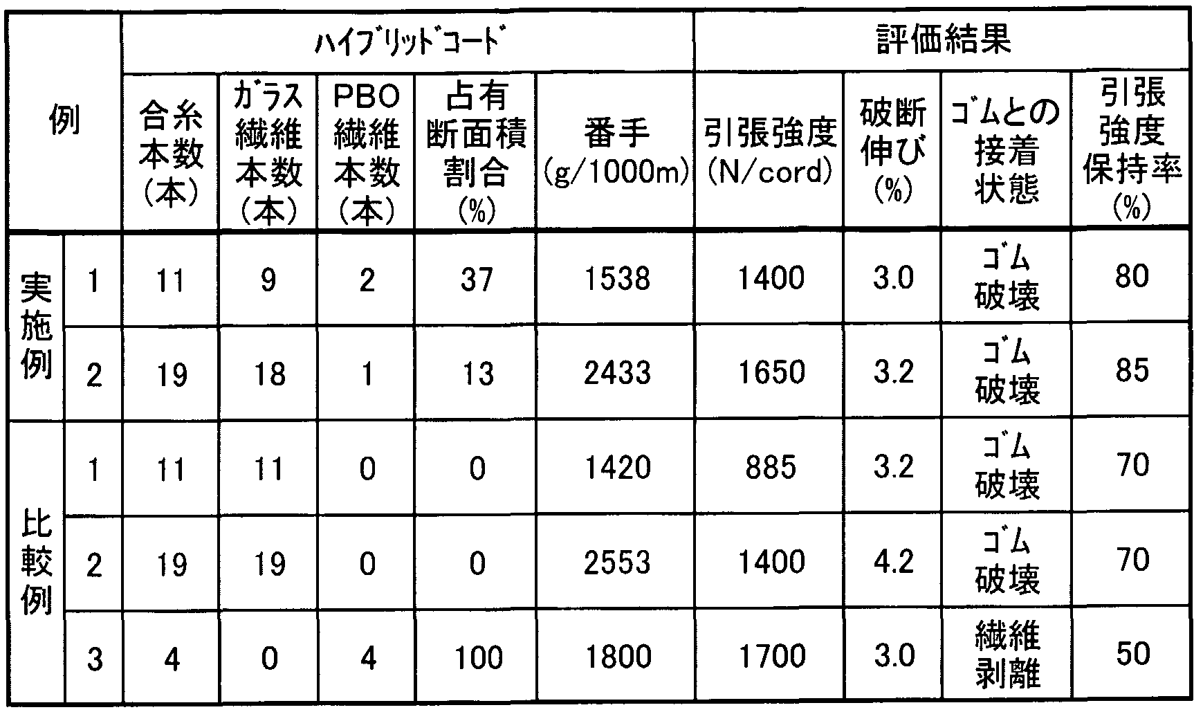
- Glass fiber strand of glass composition (outer diameter about 0.35 mm, filament diameter 9 ⁇ m, number of filaments 600, elastic modulus 70 GPa, density about 2.5 g / cm 3 , RFL adhesion 20 % By weight, manufactured by Nippon Sheet Glass Co., Ltd.). Then, two PBO fiber strands are placed at the center of the cord, and nine glass fiber strands are placed at the periphery of the cord, so that the arrangement shown in FIG. A hybrid cord (outer diameter approx. L mm) was created by twisting with a top of 25 mm. Table 3 shows the occupied cross-sectional area ratio of the PBO fiber strands in this cord and the cord count (weight g per 1,000 m length).
- the cord was coated with a second treating agent having the composition shown in Table 1 and dried, and its tensile strength and elongation at break were measured.
- the solid deposition amount of the second treating agent was 5% by weight. 2nd treatment agent composition (parts by weight)
- Matrix core composition (parts by weight)
- the cord was gripped separately with two clips and pulled up and down to peel off the cord from the sheet, and the state of adhesion of the peeled surface was examined.
- this test piece 10 was connected to a bending tester comprising one flat pulley 11 having a diameter of 25 mm, a motor (not shown), and four guide pulleys 13. It was built on plies 11 and 13. Then, a weight was attached to one end of the test piece 10 to give an initial tension of 9.8 N to the test piece 10, and the other end 12 of the test piece 10 was moved 10 cm in the direction of the arrow by a motor. It was reciprocated a distance and was repeatedly bent at a location along the flat pulley 11. The specimen was bent by reciprocating 100 times at room temperature, and the tensile strength (per cord) after the bending test was measured to evaluate the bending fatigue properties. (Per book) was determined as the tensile strength retention (%). Table 3 shows the evaluation results of the tensile strength, elongation at break, adhesion state to the matrix rubber, and retention of tensile strength after the bending test.
- Example 2 The production and evaluation of the cord were performed in the same manner as in Example 1 except that the arrangement of the strands was changed as shown in FIG.3b using one PBO fiber strand and 18 glass fiber strands. Was carried out. Table 3 shows the evaluation results.
- Example 2 Instead of the two PBO fiber strands used in Example 1, the two glass fiber strands were used, except that all the strands 11 constituting the cord were RFL-treated glass fiber strands. Code production and evaluation were performed in the same manner as in Example 1. Table 3 shows the evaluation results.
- Example 2 Instead of one PB ⁇ fiber strand used in Example 2, one glass fiber strand was used, and all 19 strands constituting the code were RFL-treated glass fiber strands. Code preparation and evaluation were performed in the same manner as in Example 2 except for the above. Table 3 shows the evaluation results.
- Comparative Example 3 using a cord composed of only a PBO fiber strand the tensile strength was high, but the adhesion to rubber was poor, and the tensile strength retention was low.
- rubber reinforcement having sufficient tensile strength suitable for a rubber reinforcing cord, excellent bending fatigue resistance, adhesion to rubber, and dimensional stability. And a rubber belt and other rubber products reinforced with the hybrid cord for rubber reinforcement and having high strength, excellent in bending resistance, durability and dimensional stability.
Landscapes
- Engineering & Computer Science (AREA)
- Mechanical Engineering (AREA)
- Textile Engineering (AREA)
- Yarns And Mechanical Finishing Of Yarns Or Ropes (AREA)
- Treatments For Attaching Organic Compounds To Fibrous Goods (AREA)
- Ropes Or Cables (AREA)
- Tires In General (AREA)
Description


Claims
Priority Applications (4)
| Application Number | Priority Date | Filing Date | Title |
|---|---|---|---|
| CA002474651A CA2474651C (en) | 2002-03-22 | 2003-03-10 | Hybrid cord for reinforcing rubber and rubber product |
| EP03744988A EP1489207B1 (en) | 2002-03-22 | 2003-03-10 | Hybrid cord for reinforcing rubber and rubber product |
| KR1020047014800A KR100909406B1 (ko) | 2002-03-22 | 2003-03-10 | 고무 보강용 하이브리드 코드 및 고무 제품 |
| US10/866,876 US7404426B2 (en) | 2002-03-22 | 2004-06-15 | Hybrid cord for rubber reinforcement and rubber product employing the same |
Applications Claiming Priority (2)
| Application Number | Priority Date | Filing Date | Title |
|---|---|---|---|
| JP2002-81257 | 2002-03-22 | ||
| JP2002081257A JP3864820B2 (ja) | 2002-03-22 | 2002-03-22 | ゴム補強用ハイブリッドコード及びゴム製品 |
Related Child Applications (1)
| Application Number | Title | Priority Date | Filing Date |
|---|---|---|---|
| US10/866,876 Continuation US7404426B2 (en) | 2002-03-22 | 2004-06-15 | Hybrid cord for rubber reinforcement and rubber product employing the same |
Publications (1)
| Publication Number | Publication Date |
|---|---|
| WO2003080907A1 true WO2003080907A1 (en) | 2003-10-02 |
Family
ID=28449115
Family Applications (1)
| Application Number | Title | Priority Date | Filing Date |
|---|---|---|---|
| PCT/JP2003/002764 WO2003080907A1 (en) | 2002-03-22 | 2003-03-10 | Hybrid cord for reinforcing rubber and rubber product |
Country Status (7)
| Country | Link |
|---|---|
| US (1) | US7404426B2 (ja) |
| EP (1) | EP1489207B1 (ja) |
| JP (1) | JP3864820B2 (ja) |
| KR (1) | KR100909406B1 (ja) |
| CN (1) | CN1643200A (ja) |
| CA (1) | CA2474651C (ja) |
| WO (1) | WO2003080907A1 (ja) |
Cited By (2)
| Publication number | Priority date | Publication date | Assignee | Title |
|---|---|---|---|---|
| WO2006000735A1 (en) * | 2004-06-23 | 2006-01-05 | Dunlop Oil & Marine Limited | Hybrid hose reinforcements |
| EP1616993A4 (en) * | 2003-04-09 | 2007-08-01 | Nippon Sheet Glass Co Ltd | REINFORCING STRING FOR REINFORCING RUBBER AND RUBBER PRODUCT USING THE SAME |
Families Citing this family (23)
| Publication number | Priority date | Publication date | Assignee | Title |
|---|---|---|---|---|
| BRPI0418562B1 (pt) * | 2004-02-23 | 2017-10-24 | Dayco Europe S.R.L. | Toothed belt |
| BRPI0419078A (pt) * | 2004-09-29 | 2007-12-18 | Dayco Europe Srl | transmissão por correia dentada para uso com óleo |
| JP4712408B2 (ja) * | 2005-02-18 | 2011-06-29 | 智深 呉 | ドライハイブリッド強化繊維緊張材 |
| FR2897076B1 (fr) * | 2006-02-09 | 2008-04-18 | Michelin Soc Tech | Cable composite elastique pour pneumatique. |
| WO2007114392A1 (ja) * | 2006-03-30 | 2007-10-11 | Kyocera Corporation | 配線基板および実装構造体 |
| US8932165B2 (en) | 2006-03-31 | 2015-01-13 | The Gates Corporation | Toothed power transmission belt |
| RU2405682C1 (ru) * | 2006-12-26 | 2010-12-10 | Бриджстоун Корпорейшн | Пневматическая шина |
| WO2009063952A1 (ja) | 2007-11-15 | 2009-05-22 | Nippon Sheet Glass Company, Limited | 補強用コードおよびそれを用いたゴム製品 |
| BRPI0822460B1 (pt) | 2008-06-19 | 2019-05-07 | Dayco Europe S.R.L. | Conjunto alternador de partida compreendendo uma correia poli-v e correia poli-v. |
| EP2367990A1 (en) * | 2008-12-18 | 2011-09-28 | NV Bekaert SA | A cord for reinforcement of a cementitious matrix |
| US8496423B2 (en) | 2009-09-10 | 2013-07-30 | National Oilwell Varco, L.P. | Windmill conveyance system and method for using same |
| KR101353700B1 (ko) * | 2010-09-17 | 2014-01-21 | 코오롱인더스트리 주식회사 | 혼합 섬유 및 그 제조방법 |
| US9109328B2 (en) * | 2011-06-10 | 2015-08-18 | Nv Bekaert Sa | Steel cord comprising flat wires |
| WO2014126543A1 (en) * | 2013-02-12 | 2014-08-21 | Kordsa Global Endustriyel Iplik Ve Kordbezi Sanayi Ve Ticaret A.S. | A hybrid cord |
| US10113296B2 (en) * | 2013-10-01 | 2018-10-30 | Bright Technologies, L.L.C. | Dragline bucket rigging system |
| KR101528464B1 (ko) * | 2014-04-09 | 2015-06-12 | 유한회사 태광타이어 | 아라미드 탄소섬유 코트지 및 이를 이용한 트럭버스용 재생타이어의 제조방법 |
| JP6177198B2 (ja) * | 2014-06-30 | 2017-08-09 | ゲイツ・ユニッタ・アジア株式会社 | 歯付きベルト |
| KR101599477B1 (ko) * | 2014-07-11 | 2016-03-14 | 임수영 | Tw-섬유단에 열가소성 수지가 코팅된 탄소섬유 복합체, 이의 제조방법 및 이의 제조장치 |
| WO2017110076A1 (ja) * | 2015-12-21 | 2017-06-29 | 日本板硝子株式会社 | ゴム補強用コード及びそれを用いたゴム製品 |
| DE102017222896A1 (de) | 2017-12-15 | 2019-07-25 | Continental Reifen Deutschland Gmbh | Hybridcord zur Verwendung als Festigkeitsträger in einer Gürtelbandage eines Fahrzeugluftreifens, Verfahren zu dessen Herstellung und Verwendung |
| JP2020190058A (ja) * | 2019-05-22 | 2020-11-26 | 株式会社イノアックコーポレーション | 繊維ストランド、補強マット、ボード及び繊維ストランドの製造方法 |
| CN112921464B (zh) * | 2021-01-29 | 2022-04-22 | 福建强纶新材料股份有限公司 | 一种弹性复合丝线及其制备方法 |
| CN114293381A (zh) * | 2022-01-07 | 2022-04-08 | 嘉兴博蕾新材料有限公司 | 一种车胎骨架帘子布浸胶工艺 |
Citations (7)
| Publication number | Priority date | Publication date | Assignee | Title |
|---|---|---|---|---|
| EP0293263A1 (en) * | 1987-05-28 | 1988-11-30 | The Yokohama Rubber Co., Ltd. | Rubber-reinforcing cords and radial-ply tires using the same |
| JPH0217596U (ja) * | 1988-07-22 | 1990-02-05 | ||
| JPH06300085A (ja) * | 1993-04-13 | 1994-10-25 | Bridgestone Corp | コンベアベルト |
| JPH06297905A (ja) * | 1993-04-14 | 1994-10-25 | Bridgestone Corp | 空気入りラジアルタイヤ |
| JPH09250041A (ja) * | 1996-03-15 | 1997-09-22 | Bridgestone Corp | 有機繊維双撚りコ─ド |
| JPH10329507A (ja) * | 1997-06-04 | 1998-12-15 | Toyobo Co Ltd | ゴム補強用ディップコード |
| JP2001336038A (ja) * | 2000-05-29 | 2001-12-07 | Toyobo Co Ltd | ゴム補強用繊維 |
Family Cites Families (22)
| Publication number | Priority date | Publication date | Assignee | Title |
|---|---|---|---|---|
| US3029590A (en) * | 1958-12-30 | 1962-04-17 | Owens Corning Fiberglass Corp | Extensible fibrous glass textile strand structure and method of making same |
| US3446003A (en) * | 1967-01-03 | 1969-05-27 | Ppg Industries Inc | Glass fiber cord construction |
| US3495646A (en) * | 1968-02-21 | 1970-02-17 | Owens Corning Fiberglass Corp | Reinforcement for vulcanized rubberlike products and method of making same |
| US4155394A (en) * | 1977-08-29 | 1979-05-22 | The Goodyear Tire & Rubber Company | Tire cord composite and pneumatic tire |
| US4389839A (en) * | 1980-01-16 | 1983-06-28 | Akzo Nv | Reinforcing cord for elastomeric articles, shaped articles of reinforced elastomeric material, more particularly pneumatic tires for vehicles, and a process for the manufacture of reinforcing cord and a process for the manufacture of vehicle tires |
| JPS5921787A (ja) * | 1982-07-23 | 1984-02-03 | 横浜ゴム株式会社 | ゴム補強用炭素繊維複合コ−ド |
| US4499716A (en) * | 1983-06-13 | 1985-02-19 | E. I. Du Pont De Nemours And Company | Reinforcement structure |
| US4852625A (en) * | 1984-04-10 | 1989-08-01 | Mitsubishi Belting Ltd. | Tire for two-wheeled vehicle in which individual cord belts contain both adhesive and reinforcing cords |
| JPS63295780A (ja) * | 1987-05-28 | 1988-12-02 | 横浜ゴム株式会社 | ゴム補強用スチ−ルワイヤ複合コ−ド |
| JPH01118686A (ja) * | 1987-10-27 | 1989-05-11 | Yokohama Rubber Co Ltd:The | 乗用車用ラジアルタイヤ |
| JPS6470202A (en) | 1987-06-17 | 1989-03-15 | Yokohama Rubber Co Ltd | Radial tire for car |
| JPH0217596A (ja) | 1988-07-06 | 1990-01-22 | Fujitsu Ltd | 通帳取扱装置 |
| US5948186A (en) * | 1993-02-09 | 1999-09-07 | Toyobo Co., Ltd. | Light weight tire including polybenzazole fibers |
| JPH06286409A (ja) * | 1993-03-30 | 1994-10-11 | Bridgestone Corp | 空気入りラジアルタイヤ |
| EP0661179B1 (en) * | 1993-12-28 | 1997-05-21 | Sumitomo Rubber Industries Limited | Pneumatic radial tyre |
| JPH08174708A (ja) | 1994-12-27 | 1996-07-09 | Bando Chem Ind Ltd | ベルト抗張体の製造方法 |
| JPH0949139A (ja) * | 1995-08-09 | 1997-02-18 | Toyobo Co Ltd | コード及びディップコード |
| JP3427714B2 (ja) | 1998-01-23 | 2003-07-22 | 日本板硝子株式会社 | ゴム補強用ガラス繊維コード |
| JPH11336847A (ja) | 1998-05-25 | 1999-12-07 | Bando Chem Ind Ltd | 伝動ベルト用抗張体及び伝動ベルト |
| US6601378B1 (en) * | 1999-09-08 | 2003-08-05 | Honeywell International Inc. | Hybrid cabled cord and a method to make it |
| US6539698B2 (en) * | 2001-01-19 | 2003-04-01 | Continental Ag | Wrapped cord |
| JP4018460B2 (ja) * | 2002-06-10 | 2007-12-05 | 日本板硝子株式会社 | ゴム補強用コードおよびそれを含有するゴム製品 |
-
2002
- 2002-03-22 JP JP2002081257A patent/JP3864820B2/ja not_active Expired - Fee Related
-
2003
- 2003-03-10 EP EP03744988A patent/EP1489207B1/en not_active Expired - Fee Related
- 2003-03-10 CN CNA03806751XA patent/CN1643200A/zh active Pending
- 2003-03-10 CA CA002474651A patent/CA2474651C/en not_active Expired - Fee Related
- 2003-03-10 KR KR1020047014800A patent/KR100909406B1/ko not_active IP Right Cessation
- 2003-03-10 WO PCT/JP2003/002764 patent/WO2003080907A1/ja active Application Filing
-
2004
- 2004-06-15 US US10/866,876 patent/US7404426B2/en not_active Expired - Lifetime
Patent Citations (7)
| Publication number | Priority date | Publication date | Assignee | Title |
|---|---|---|---|---|
| EP0293263A1 (en) * | 1987-05-28 | 1988-11-30 | The Yokohama Rubber Co., Ltd. | Rubber-reinforcing cords and radial-ply tires using the same |
| JPH0217596U (ja) * | 1988-07-22 | 1990-02-05 | ||
| JPH06300085A (ja) * | 1993-04-13 | 1994-10-25 | Bridgestone Corp | コンベアベルト |
| JPH06297905A (ja) * | 1993-04-14 | 1994-10-25 | Bridgestone Corp | 空気入りラジアルタイヤ |
| JPH09250041A (ja) * | 1996-03-15 | 1997-09-22 | Bridgestone Corp | 有機繊維双撚りコ─ド |
| JPH10329507A (ja) * | 1997-06-04 | 1998-12-15 | Toyobo Co Ltd | ゴム補強用ディップコード |
| JP2001336038A (ja) * | 2000-05-29 | 2001-12-07 | Toyobo Co Ltd | ゴム補強用繊維 |
Non-Patent Citations (1)
| Title |
|---|
| See also references of EP1489207A4 * |
Cited By (3)
| Publication number | Priority date | Publication date | Assignee | Title |
|---|---|---|---|---|
| EP1616993A4 (en) * | 2003-04-09 | 2007-08-01 | Nippon Sheet Glass Co Ltd | REINFORCING STRING FOR REINFORCING RUBBER AND RUBBER PRODUCT USING THE SAME |
| US7682274B2 (en) * | 2003-04-09 | 2010-03-23 | Nippon Sheet Glass Company, Limited | Reinforcing cord for rubber reinforcement and rubber product including the same |
| WO2006000735A1 (en) * | 2004-06-23 | 2006-01-05 | Dunlop Oil & Marine Limited | Hybrid hose reinforcements |
Also Published As
| Publication number | Publication date |
|---|---|
| EP1489207A4 (en) | 2011-01-05 |
| US7404426B2 (en) | 2008-07-29 |
| CA2474651A1 (en) | 2003-10-02 |
| US20040226641A1 (en) | 2004-11-18 |
| JP2003278047A (ja) | 2003-10-02 |
| EP1489207B1 (en) | 2012-08-22 |
| KR20050002875A (ko) | 2005-01-10 |
| KR100909406B1 (ko) | 2009-07-24 |
| CA2474651C (en) | 2010-02-02 |
| CN1643200A (zh) | 2005-07-20 |
| JP3864820B2 (ja) | 2007-01-10 |
| EP1489207A1 (en) | 2004-12-22 |
Similar Documents
| Publication | Publication Date | Title |
|---|---|---|
| WO2003080907A1 (en) | Hybrid cord for reinforcing rubber and rubber product | |
| JP4295763B2 (ja) | ゴムを補強するための補強用コードおよびそれを用いたゴム製品 | |
| EP2221413B1 (en) | Reinforcing cord and rubber product using the same | |
| JP3846236B2 (ja) | ハイブリッドコード及びゴム補強物 | |
| JP4018460B2 (ja) | ゴム補強用コードおよびそれを含有するゴム製品 | |
| EP1980657B1 (en) | Cord for rubber reinforcement | |
| WO2005061766A1 (ja) | ゴム補強用コードおよびそれを用いたゴム製品 | |
| JP6764420B2 (ja) | ゴム補強用コード及びそれを用いたゴム製品 | |
| JP2004285498A (ja) | ハイブリッドコード | |
| JPH11336847A (ja) | 伝動ベルト用抗張体及び伝動ベルト | |
| JPH0692488B2 (ja) | 繊維補強ゴム製品 |
Legal Events
| Date | Code | Title | Description |
|---|---|---|---|
| AK | Designated states |
Kind code of ref document: A1 Designated state(s): CA CN KR US |
|
| AL | Designated countries for regional patents |
Kind code of ref document: A1 Designated state(s): AT BE BG CH CY CZ DE DK EE ES FI FR GB GR HU IE IT LU MC NL PT RO SE SI SK TR |
|
| 121 | Ep: the epo has been informed by wipo that ep was designated in this application | ||
| WWE | Wipo information: entry into national phase |
Ref document number: 10866876 Country of ref document: US |
|
| WWE | Wipo information: entry into national phase |
Ref document number: 2474651 Country of ref document: CA |
|
| WWE | Wipo information: entry into national phase |
Ref document number: 2003744988 Country of ref document: EP |
|
| WWE | Wipo information: entry into national phase |
Ref document number: 1020047014800 Country of ref document: KR |
|
| WWE | Wipo information: entry into national phase |
Ref document number: 2003806751X Country of ref document: CN |
|
| WWP | Wipo information: published in national office |
Ref document number: 2003744988 Country of ref document: EP |
|
| WWP | Wipo information: published in national office |
Ref document number: 1020047014800 Country of ref document: KR |