US9845403B2 - Ink image matter generating method - Google Patents
Ink image matter generating method Download PDFInfo
- Publication number
- US9845403B2 US9845403B2 US15/595,169 US201715595169A US9845403B2 US 9845403 B2 US9845403 B2 US 9845403B2 US 201715595169 A US201715595169 A US 201715595169A US 9845403 B2 US9845403 B2 US 9845403B2
- Authority
- US
- United States
- Prior art keywords
- ink
- color
- fluorescent
- medium
- droplets
- Prior art date
- Legal status (The legal status is an assumption and is not a legal conclusion. Google has not performed a legal analysis and makes no representation as to the accuracy of the status listed.)
- Active
Links
Images


Classifications
-
- C—CHEMISTRY; METALLURGY
- C09—DYES; PAINTS; POLISHES; NATURAL RESINS; ADHESIVES; COMPOSITIONS NOT OTHERWISE PROVIDED FOR; APPLICATIONS OF MATERIALS NOT OTHERWISE PROVIDED FOR
- C09D—COATING COMPOSITIONS, e.g. PAINTS, VARNISHES OR LACQUERS; FILLING PASTES; CHEMICAL PAINT OR INK REMOVERS; INKS; CORRECTING FLUIDS; WOODSTAINS; PASTES OR SOLIDS FOR COLOURING OR PRINTING; USE OF MATERIALS THEREFOR
- C09D11/00—Inks
- C09D11/30—Inkjet printing inks
- C09D11/40—Ink-sets specially adapted for multi-colour inkjet printing
-
- B—PERFORMING OPERATIONS; TRANSPORTING
- B41—PRINTING; LINING MACHINES; TYPEWRITERS; STAMPS
- B41J—TYPEWRITERS; SELECTIVE PRINTING MECHANISMS, i.e. MECHANISMS PRINTING OTHERWISE THAN FROM A FORME; CORRECTION OF TYPOGRAPHICAL ERRORS
- B41J2/00—Typewriters or selective printing mechanisms characterised by the printing or marking process for which they are designed
- B41J2/005—Typewriters or selective printing mechanisms characterised by the printing or marking process for which they are designed characterised by bringing liquid or particles selectively into contact with a printing material
- B41J2/01—Ink jet
- B41J2/21—Ink jet for multi-colour printing
-
- B—PERFORMING OPERATIONS; TRANSPORTING
- B41—PRINTING; LINING MACHINES; TYPEWRITERS; STAMPS
- B41J—TYPEWRITERS; SELECTIVE PRINTING MECHANISMS, i.e. MECHANISMS PRINTING OTHERWISE THAN FROM A FORME; CORRECTION OF TYPOGRAPHICAL ERRORS
- B41J2/00—Typewriters or selective printing mechanisms characterised by the printing or marking process for which they are designed
- B41J2/52—Arrangement for printing a discrete number of tones, not covered by group B41J2/205, e.g. applicable to two or more kinds of printing or marking process
-
- B—PERFORMING OPERATIONS; TRANSPORTING
- B44—DECORATIVE ARTS
- B44F—SPECIAL DESIGNS OR PICTURES
- B44F1/00—Designs or pictures characterised by special or unusual light effects
- B44F1/08—Designs or pictures characterised by special or unusual light effects characterised by colour effects
-
- C—CHEMISTRY; METALLURGY
- C09—DYES; PAINTS; POLISHES; NATURAL RESINS; ADHESIVES; COMPOSITIONS NOT OTHERWISE PROVIDED FOR; APPLICATIONS OF MATERIALS NOT OTHERWISE PROVIDED FOR
- C09D—COATING COMPOSITIONS, e.g. PAINTS, VARNISHES OR LACQUERS; FILLING PASTES; CHEMICAL PAINT OR INK REMOVERS; INKS; CORRECTING FLUIDS; WOODSTAINS; PASTES OR SOLIDS FOR COLOURING OR PRINTING; USE OF MATERIALS THEREFOR
- C09D11/00—Inks
- C09D11/30—Inkjet printing inks
- C09D11/32—Inkjet printing inks characterised by colouring agents
- C09D11/322—Pigment inks
-
- C—CHEMISTRY; METALLURGY
- C09—DYES; PAINTS; POLISHES; NATURAL RESINS; ADHESIVES; COMPOSITIONS NOT OTHERWISE PROVIDED FOR; APPLICATIONS OF MATERIALS NOT OTHERWISE PROVIDED FOR
- C09D—COATING COMPOSITIONS, e.g. PAINTS, VARNISHES OR LACQUERS; FILLING PASTES; CHEMICAL PAINT OR INK REMOVERS; INKS; CORRECTING FLUIDS; WOODSTAINS; PASTES OR SOLIDS FOR COLOURING OR PRINTING; USE OF MATERIALS THEREFOR
- C09D11/00—Inks
- C09D11/50—Sympathetic, colour changing or similar inks
-
- H—ELECTRICITY
- H04—ELECTRIC COMMUNICATION TECHNIQUE
- H04N—PICTORIAL COMMUNICATION, e.g. TELEVISION
- H04N1/00—Scanning, transmission or reproduction of documents or the like, e.g. facsimile transmission; Details thereof
- H04N1/46—Colour picture communication systems
- H04N1/54—Conversion of colour picture signals to a plurality of signals some of which represent particular mixed colours, e.g. for textile printing
-
- H—ELECTRICITY
- H04—ELECTRIC COMMUNICATION TECHNIQUE
- H04N—PICTORIAL COMMUNICATION, e.g. TELEVISION
- H04N1/00—Scanning, transmission or reproduction of documents or the like, e.g. facsimile transmission; Details thereof
- H04N1/46—Colour picture communication systems
- H04N1/56—Processing of colour picture signals
- H04N1/60—Colour correction or control
-
- B—PERFORMING OPERATIONS; TRANSPORTING
- B41—PRINTING; LINING MACHINES; TYPEWRITERS; STAMPS
- B41M—PRINTING, DUPLICATING, MARKING, OR COPYING PROCESSES; COLOUR PRINTING
- B41M5/00—Duplicating or marking methods; Sheet materials for use therein
-
- B—PERFORMING OPERATIONS; TRANSPORTING
- B41—PRINTING; LINING MACHINES; TYPEWRITERS; STAMPS
- B41M—PRINTING, DUPLICATING, MARKING, OR COPYING PROCESSES; COLOUR PRINTING
- B41M5/00—Duplicating or marking methods; Sheet materials for use therein
- B41M5/0023—Digital printing methods characterised by the inks used
-
- H—ELECTRICITY
- H04—ELECTRIC COMMUNICATION TECHNIQUE
- H04N—PICTORIAL COMMUNICATION, e.g. TELEVISION
- H04N1/00—Scanning, transmission or reproduction of documents or the like, e.g. facsimile transmission; Details thereof
- H04N1/46—Colour picture communication systems
- H04N1/56—Processing of colour picture signals
- H04N1/60—Colour correction or control
- H04N1/6097—Colour correction or control depending on the characteristics of the output medium, e.g. glossy paper, matt paper, transparency or fabrics
Definitions
- the present invention relates to an ink image matter generating method, and more particularly, to an ink image matter generating method capable of manufacturing an ink image matter on which an ink image in which color reproducibility of a specific color is enhanced using a fluorescent ink is drawn, in drawing an ink image onto a printing substrate medium, particularly, a chromatic color printing substrate medium, for example, a special printing substrate medium such as a cardboard, for example, using inkjet printing.
- a printing substrate medium particularly, a chromatic color printing substrate medium, for example, a special printing substrate medium such as a cardboard, for example, using inkjet printing.
- color inks such as cyan, magenta, and yellow have been used. Tint or vividness of such a color image is influenced by a color of a surface to be printed of a printing substrate medium. For this reason, in the related art, in order to reproduce a high-definition color image, a medium such as inkjet paper with high whiteness of a surface to be printed or inkjet glossy paper has been used.
- a printing substrate medium such as general printing paper which is generally used
- whiteness or visible light reflectance is low compared with inkjet paper.
- paper that is white but has tint for example, in a white printing substrate medium with a yellowish ground color on a surface to be printed, such as recycled paper or official postcards, or in a chromatic color printing substrate medium such as color printing paper, light is absorbed in a specific wavelength band in a visible light wavelength region, and thus, reflectance may not be uniform, and coloring may not be sufficient.
- a chromatic color printing substrate medium particularly, in printing with respect to a special printing substrate medium such as a cardboard, generally, the number of colors to be printed is limited.
- specific 18 colors are regulated as a standard for cardboard printing colors, which is the Standard of Japan Corrugated Industry Association (JCS: standard of colors to be printed on cardboard industry standard M0001-2000 cardboard).
- JP2002-038063A proposes an inkjet recording method using a white ink to be used for substrate treatment of a recording medium on which an image is to be formed, or complementary color treatment depending on a ground color of the recording medium, in addition to color inks.
- JP2002-038063A even in a case where color printing is performed with respect to a white recoding medium with a yellowish ground color of a surface to be printed, or colored paper, it is possible to reproduce a bright color image without being influenced by the ground color of the recording medium.
- JP2005-125643A proposes an image forming method using a white ink containing white pigments and an ink containing a fluorescent whitening agent, in addition to color inks containing color coloring materials.
- JP2005-125643A by jetting the ink containing the fluorescent whitening agent on a color image formed by the color inks and/or a white image formed by the white ink to form a coating layer, it is possible to reproduce an image with colors similar to fluorescent colors as a color image, and to obtain a white image with extremely high brightness. Further, it is possible to recognize a color image contiguous to the white image with high brightness as an image with higher saturation according to visual characteristics of color recognition based on comparison with white, to thereby obtain an excellent image in a white background characteristic, drawability of a color image and image storability.
- JP2011-522972A proposes a fluorescent whitening agent composition for whitening paper used in a paper manufacturing process to obtain paper with high whiteness.
- the fluorescent whitening agent composition disclosed in JP2011-522972A may be used to enhance printing performance of inkjet printing. Further, the fluorescent whitening agent composition may be used for the ink containing the fluorescent whitening agent disclosed in JP2005-125643A.
- a color image contiguous to a white image with high brightness is recognized as an image with higher saturation, according to visual characteristics based on comparison with white.
- a color image is formed on a ground color of a chromatic color printing substrate medium such as color printing paper or a cardboard without using a white ink, a high-definition color image cannot be reproduced with respect to the ground color of the chromatic color printing substrate medium.
- chromatic color printing substrate mediums have various different ground colors, even if inkjet printing is performed on the ground colors of the chromatic color printing substrate mediums to form color images, in many cases, light is absorbed in a specific wavelength band, and thus, reflectance is lowered, coloring deteriorates, and color reproducibility is lowered.
- by simply jetting the ink containing the fluorescent whitening agent according to the ground colors of the chromatic color printing substrate mediums it is not possible to ensure color reproducibility of a specific color in which the color reproducibility is lowered, and it is not possible to reproduce a high-definition color image.
- the ink containing the fluorescent whitening agent disclosed in JP2005-125643A can be used as the fluorescent whitening agent.
- the technique since the technique discloses characteristic improvement of the fluorescent whitening agent composition, the technique does not disclose any method for enhancement of color reproducibility in a specific color in which reflectance is lowered in a specific local wavelength region of visible light and color reproducibility cannot be ensured, as in a chromatic color printing substrate medium, for example.
- an object of the invention is to provide an ink image matter generating method capable of securing, by selecting and using an appropriate fluorescent ink suitable for realizing high color reproducibility with respect to a specific color of which color reproducibility cannot be ensured using only color inks in inkjet printing on a printing substrate medium (hereinafter, referred to as a medium), particularly, on a chromatic color medium, high color reproducibility with respect to the specific color.
- a medium a printing substrate medium
- Another object of the invention is to provide an ink image matter generating method capable of securing high color reproducibility with respect to a specific color, by jetting droplets of a fluorescent ink at an appropriate droplet jetting position with respect to a color ink, in addition to the above-mentioned object.
- Still another object of the invention is to provide an ink image matter generating method capable of securing high color reproducibility with respect to a specific color by determining an appropriate droplet jetting amount of a fluorescent ink for a color ink and jetting droplets of the fluorescent ink by the determined droplet jetting amount, in addition to the above-mentioned objects.
- an ink image matter generating method for, when jetting droplets of an inkjet color ink on a medium to generate an ink image matter, selecting a fluorescent ink in the following processes (a) to (c), and jetting droplets of the selected fluorescent ink together with the color ink, or after the droplets of the color ink are jetted to cause the fluorescent ink to exist on a surface of the ink image matter.
- the processes are (a) a process of color-measuring a target color which is a target of color reproduction on the medium and the medium on which the color ink for color reproduction of the target color is printed; (b) a process of calculating a difference between a colorimetric value of the target color and a colorimetric value of the medium on which the color ink is printed; and (c) a process of selecting a fluorescent ink for reducing the difference between the colorimetric value of the target color and the colorimetric value of the medium on which the color ink is printed, from fluorescent inks that are set in advance.
- the medium is a chromatic color medium.
- wavelengths of respective colors of red R, green G, and blue B are represented as ⁇ R , ⁇ G , and ⁇ B , respectively
- wavelengths in which a light emitting spectrum becomes a maximum with respect to three fluorescent inks of an R light emitting fluorescent ink, a G light emitting fluorescent ink, and a B light emitting fluorescent ink which are set in advance are represented as ⁇ R ′, ⁇ G ′, and ⁇ B ′, respectively
- the nearest wavelengths on a short wavelength side at the time of 2% of maximum light emitting spectrum values are represented as ⁇ R ′left, ⁇ G ′left, and ⁇ B ′left
- the nearest wavelengths on a long wavelength side at the time of 2% of the maximum light emitting spectrum values are represented as ⁇ R ′right, ⁇ G ′right, and ⁇ B ′right
- each of three integrated differences of the respective colors of red R, green G, and blue B obtained by integrating a difference between reflection spectrums of each
- a fluorescent ink having a wavelength band of a color corresponding to the maximum integrated difference as a wavelength band of a light emitting spectrum is selected.
- a fluorescent ink having a wavelength band of a color corresponding to the maximum short wavelength difference as an excitation wavelength band is selected.
- the droplets of the color ink are jetted on the medium, the droplets of the fluorescent ink are jetted on the color ink on the medium to cause the fluorescent ink to exist on the surface of the ink image matter.
- the fluorescent ink is mixed with the color ink, and the droplets of the fluorescent ink are jetted on the medium together with the color ink to cause the fluorescent ink to exist on the surface of the ink image matter.
- a wavelength of the nearest intersection on a short wavelength side when seen from a maximum wavelength in which the excitation spectrum of the fluorescent ink becomes a maximum is represented as ⁇ color left
- a wavelength of the nearest intersection on a long wavelength side when seen from the maximum wavelength is represented as ⁇ color right
- integrated differences corresponding to the number of the plurality of color inks obtained by integrating a difference between the excitation spectrum of the selected fluorescent ink and the reflection spectrum of each color ink among the plurality of color inks for generating the ink image matter in a wavelength band of ⁇ color left ⁇ color ⁇ color right one color ink having the largest value among the integrated differences is referred to as a color ink A and the other one or more color inks are referred to as a color ink B, as a fluorescent ink drop
- the droplets of the fluorescent ink are also jetted in a region where the droplets of the color ink A are jetted, in addition to the region where the droplets of the color ink A are not jetted, together with the color ink A or after the droplets of the color ink A are jetted, so that the fluorescent ink is caused to exist on the surface of the ink image matter.
- a droplet jetting amount of the fluorescent ink is determined in the following processes (d) to (g), and the droplets of the fluorescent ink corresponding to the selected droplet jetting amount are jetted together with the color ink or after the droplets of the color ink are jetted.
- the processes are (d) a process of generating patches of a plurality of ink image matters generated by varying a droplet jetting amount of each color ink and a droplet jetting amount of the fluorescent ink; (e) a process of color-measuring the target color and all the patches of the plurality of ink image matters; (f) a process of calculating differences between a colorimetric value of the target color and colorimetric values of all the patches for each color ink; and (g) a process of selecting a droplet jetting amount of each color ink and a droplet jetting amount of the fluorescent ink in which a colorimetric value difference becomes a minimum, for each color ink.
- a medium a printing substrate medium
- a chromatic color medium with respect to a specific color in which color reproducibility cannot be ensured only using a color ink
- FIG. 1 is a flowchart showing an example of an ink image matter generating method according to an embodiment of the invention.
- FIG. 2 is a diagram showing an example of a flow of a determination process of a droplet jetting amount of a fluorescent ink in the ink image matter generating method shown in FIG. 1 .
- FIG. 3 is a graph showing examples of reflection spectrums of a target color and a present state color printed on a chromatic color medium used in the invention, and excitation spectrums and light emitting spectrums of a plurality of fluorescent inks, respectively.
- FIGS. 4A to 4C are graphs showing examples of reflection spectrums of a cyan ink, a chromatic color medium, and a cyan monochromatic color image on the medium, respectively.
- FIGS. 5A to 5C are graphs showing examples of reflection spectrums of a magenta ink, a chromatic color medium, and a magenta monochromatic color image on the medium, respectively.
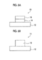
- FIGS. 6A and 6B are sectional views schematically showing configurations of ink image matters generated by the method of the invention.
- FIGS. 7A to 7D are graphs showing examples of a reflection spectrum of a cyan ink, a excitation spectrum of a fluorescent ink, a reflection spectrum of a chromatic color medium, and a reflection spectrum of a cyan monochromatic color ink image matter on the medium, respectively.
- FIGS. 8A to 8D are graphs showing examples of a reflection spectrum of a magenta ink, an excitation spectrum of a fluorescent ink, a reflection spectrum of a chromatic color medium, and a reflection spectrum of a magenta monochromatic color ink image matter on the medium, respectively.
- FIG. 9 is a graph showing examples of an excitation spectrum of one fluorescent ink and a reflection spectrum of three color inks shown in FIG. 3 .
- a medium selected in the invention is provided for forming an ink image matter by jetting of droplets of a color ink and a fluorescent ink thereon using an inkjet printer.
- the medium used in the invention is not a medium such as inkjet paper or inkjet glossy paper with high whiteness, but is a medium which has low reproducibility for a specific color due to jetting of droplets of a color ink, or a medium which cannot secure color reproducibility for some specific colors only with a color ink.
- the medium used in the invention is not particularly limited, and any medium may be used as long as the medium can enhance and improve color reproducibility of such a specific color through jetting of droplets of a fluorescent ink suitable for the specific color.
- printing paper with whiteness that is not so high may be used, and also, yellow printing paper may be used.
- a chromatic color medium for example, color printing paper, a special medium such as a cardboard (printing substrate medium), a building material, a cloth such as a nonwoven fabric or a textile, or the like may be used.
- the chromatic color medium is preferable, the special medium is more preferable, and the cardboard is the most preferable.
- an inkjet printer for generating a color image by jetting droplets of a color ink and a fluorescent ink on a medium to generate an ink image matter is not particularly limited, and any inkjet printer may be used as long as it can jet droplets of a color ink and a fluorescent ink on a medium.
- a known inkjet printer in the related art may be used.
- a colorimeter for measuring a reproduction color image of a target color generated on a medium using the target color (color patch) and the inkjet printer is not particularly limited, any colorimeter may be used as long as it can measure colorimetric values thereof.
- FIG. 1 is a flowchart showing an example of an ink image matter generating method according to an embodiment of the invention.
- FIG. 2 is a flowchart showing an example of a flow of a determination process of a droplet jetting amount of a fluorescent ink in the ink image matter generating method shown in FIG. 1 .
- a medium used for generating an ink image matter in the invention is selected.
- a chromatic color medium specifically, a cardboard is selected.
- the chromatic color medium, specifically, the cardboard is described as a representative example of the selected medium, but the invention is not limited thereto, and any medium as described above may be used.
- a target color is determined with respect to the selected medium in step S 10 .
- magenta M
- a magenta color patch (hereinafter, also referred to as a color patch) is selected.
- An example in which magenta is used as the target color is shown, but cyan (C) or yellow (Y) may be used as the target color, or a different color other than three primary colors of C, M, and Y may be used.
- the color patch used for determining the target color is not particularly limited, and any color patch may be used. Further, a known color chart or the like may be used. For example, ColorChecker made by X-Rite, Inc., ColorChart made by TOYO INK CO., LTD., or the like may be used. In a case where a cardboard is selected as the medium, it is preferable to use a color patch that at least includes regulated colors of specific 18 colors regulated as a standard for cardboard printing colors in the above-described JCS standard M0001-2000.
- step S 14 droplets of color inks for color reproduction of the target color determined in step S 12 are jetted on the medium selected in step S 10 using the inkjet printer to generate a monochromatic color image of the target color (reproduction color image).
- the target color is magenta (M)
- inkjet printing is performed using a magenta ink (M) on a cardboard which is a chromatic color medium to generate a magenta monochromatic color image.
- cyan (C) or yellow (Y) is determined as the target color
- inkjet printing may be performed using a cyan (C) ink or a yellow (Y) ink.
- a cyan (C) ink and a yellow (Y) ink may be used to generate a green (G) monochromatic color image.
- inks with respective ink amounts capable of reproducing the target color on a standard white medium using at least droplets of two color inks of a cyan (C) ink, a magenta (M) ink, and a yellow (Y) ink may be jetted on a selected medium to generate a monochromatic color image.
- the color inks may include three color inks of at least a cyan (C) ink, a magenta (M) ink, and a yellow (Y) ink, as shown in FIG. 9 (which will be described later), but in addition to these color inks, may include a color ink such as a light cyan ink, a light magenta ink, or a light yellow ink.
- the three or more color inks may be provided as an ink set for an inkjet printer.
- the color inks and the ink set used in the invention are not particularly limited, and may be a known color ink and a known ink set in the related art used in a known inkjet printer in the related art.
- a known color ink and a known ink set in the related art used in a known inkjet printer in the related art.
- an ink set of three types of color inks of a cyan (C) ink, a magenta (M) ink, and a yellow (Y) ink respectively having reflection spectrums c ( ⁇ ), m ( ⁇ ), and y ( ⁇ ) shown in FIG.
- an aqueous pigment type inkjet ink a UV curable inkjet ink, a solvent type inkjet ink, an aqueous dye type inkjet ink, or the like including light magenta (LM), light cyan (LC), or the like may be used.
- LM light magenta
- LC light cyan
- step S 16 the color patch of the target color determined in step S 12 and the monochromatic color image generated in step S 14 are respectively color-measured by a spectrophotometer.
- step S 16 corresponds to a color-measuring process (a) of the invention.
- the color measurement of the color patch of the target color and the monochromatic color image is performed under the same color measurement condition, for example, under the same lighting condition or the like.
- D50 or F8 is used as a light source when color-measuring the color patch of the target color and the monochromatic color image.
- the color measurement is performed under the same illuminance.
- FIG. 3 shows, in a case where a target color is magenta (M) and a chromatic color image of the target color is generated on a predetermined chromatic color medium, an example of a color measurement result of a color patch of the target color and a monochromatic color image.
- M magenta
- a spectral reflection spectrum t ( ⁇ ) of a target color which is a spectral color measurement result of a color patch of the target color is represented by a graph indicated by a thick line in FIG. 3
- a spectral reflection spectrum p ( ⁇ ) of a present state color which is a color measurement result of the current color of a monochromatic color image printed on a chromatic color medium is represented by a graph indicated by a thin solid line in FIG. 3 .
- the reflection spectrum p ( ⁇ ) of the current color is absorbed by a medium in a wavelength band of approximately 590 nm or longer, compared with the reflection spectrum t ( ⁇ ) of the target color, the reflection spectrum p ( ⁇ ) becomes lowered. Thus, coloring, and accordingly, color reproducibility deteriorates. For this reason, it can be understood that a difference between the reflection spectrum t ( ⁇ ) of the target color and the reflection spectrum p ( ⁇ ) of the current color is a reflection spectrum to be supplemented, and that a wavelength region where the difference exists is a wavelength region where the supplementation is necessary.
- a cyan (C) ink having a reflection spectrum (spectral reflectance characteristic (distribution)) c ( ⁇ ) shown in FIG. 4(A) are jetted on a cardboard, for example, to form a cyan monochromatic color image
- the cardboard shows a yellowish ground color on a surface to be printed and has a reflection spectrum d ( ⁇ ) shown in FIG. 4B , and thus, has a characteristic of absorbing short wavelength light.
- a cyan monochromatic color image having a reflection spectrum s1 ( ⁇ ) indicated by a solid line in FIG. 4( c ) is obtained by cooperation of both the characteristics.
- a magenta (M) ink having a reflection spectrum (spectral reflectance characteristic (distribution)) m ( ⁇ ) shown in FIG. 5(A) are jetted on a cardboard to form a magenta monochromatic color image
- the cardboard shows a yellowish ground color on a surface to be printed and has a reflection spectrum d ( ⁇ ) shown in FIG. 5(B) in a similar way to FIG. 4(B) , and thus, absorption occurs on a short wavelength side and a long wavelength side, and the cardboard becomes a magenta monochromatic color image having a reflection spectrum s2 ( ⁇ ) indicated by a solid line in FIG. 5(C) .
- the reflection spectrum s2 ( ⁇ ) of the magenta monochromatic color image shown in FIG. 5(C) is lowered in a short wavelength region and a long wavelength region, compared with the reflection spectrum m ( ⁇ ) of the magenta ink shown in FIG. 5(A) , and thus coloring of magenta is not sufficient.
- a dot line in FIG. 5(C) it can be understood that it is necessary to further increase the reflection spectrum (reflectance characteristic) in a wavelength region WB on a short wavelength side of 380 nm to 530 nm and a wavelength region WC on a long wavelength side of 580 nm to 780 nm.
- the colorimeter used in the invention is not particularly limited, any known colorimeter may be used as long as it can spectrophotometrically measure a color patch of a target color and a monochromatic color image of a medium under the same conditions.
- CM-2500c made by Konica Minolta, Inc., Ci60 made by X-Rite Inc., or the like may be used.
- step S 18 a difference between spectrocolorimetric values of the color patch of the target color and the monochromatic color image of the medium, spectrophotometrically measured in step S 16 , that is, a difference between spectral reflection spectrum distributions (reflectance characteristics) is calculated.
- Step S 18 corresponds to a calculation process (b) of calculating a difference between colorimetric values in the invention.
- a difference between spectrocolorimetric values that is, a difference ⁇ Rsp between spectral reflection spectrum distributions (reflectance characteristics) is calculated with respect to each color of red R, green G, and blue B.
- wavelengths of the respective colors of red R, green G, and blue B are respectively represented as ⁇ R , ⁇ G , and ⁇ B
- wavelengths in which a light emitting spectrum becomes a maximum with respect to the three types of fluorescent inks which are the R light emitting fluorescent ink, the G light emitting fluorescent ink, and the B light emitting fluorescent ink are respectively represented as ⁇ R ′, ⁇ G ′, and ⁇ B ′.
- the nearest wavelengths on a short wavelength side at the time of 2% of respective maximum light emitting spectrum values for the three types of fluorescent inks are represented as ⁇ R ′left, ⁇ G ′left, and ⁇ B ′left
- the nearest wavelengths on a long wavelength side at the time of 2% of respective maximum light emitting spectrum values for the three types of fluorescent inks are represented as ⁇ R ′right, ⁇ G ′right, and ⁇ B ′right.
- each color of red R, green G, and blue B as a difference between spectrocolorimetric values of a color patch of a target color and a monochromatic color image of a medium, differences between reflection spectrums of the color patch of the target color and the monochromatic color image of the medium are respectively integrated in each wavelength band of ⁇ R ′left ⁇ R ⁇ R ′right, ⁇ B ′left ⁇ B ⁇ B ′right, and ⁇ G ′left ⁇ G ⁇ G ′right, so that three integrated differences of the respective colors of red R, green G, and blue B are calculated.
- ⁇ Ri, ⁇ Gi, and ⁇ Bi of the respective colors of red R, green G, and blue B may be calculated by the following expressions (1), (2), and (3), respectively.
- ⁇ Ri ⁇ ⁇ R ′ left ⁇ R ′ right
- d ⁇ ⁇ 552 nm 693 nm
- d ⁇ 161.4
- ⁇ Gi ⁇ ⁇ G ′ left ⁇ G ′ right
- d ⁇ ⁇ 453 nm 607 nm
- d ⁇ 33.9
- ⁇ Bi ⁇ ⁇ B ′ left ⁇ B ′ right
- d ⁇ ⁇ 385 nm 576 nm
- d ⁇ 21.8 (3)
- respective wavelength regions for calculating three integrated differences of the respective colors of red R, green (G and blue B may be fixed to 546.1 nm ⁇ R ⁇ 780.0 nm, 435.8 nm ⁇ G ⁇ 700.0 nm, and 380.0 nm ⁇ B ⁇ 546.1 nm, or may be fixed to 595 nm ⁇ R ⁇ 750 nm, 490 nm ⁇ G 595 nm, and 435 nm ⁇ B ⁇ 490 nm.
- Wavelength bands other than the above-described wavelength regions may be set as long as they are suitable for calculating three integrated differences of the respective colors and three short wavelength differences.
- three types of fluorescent inks of the R light emitting fluorescent ink, the G light emitting fluorescent ink, and the B light emitting fluorescent ink corresponding to the respective colors of red R, green G, and blue B are set in advance, but the invention is not limited thereto, and as long as respective colors and fluorescent inks correspond to each other, various colors of three colors or more may be selected, or various fluorescent inks corresponding thereto may be selected and set in advance.
- step S 20 a fluorescent ink for reducing the difference between the spectrocolorimetric values of the color patch of the target color and the monochromatic color image of the medium calculated in step S 18 , that is, the difference between the spectral reflection spectrum distributions (reflectance characteristics) is selected.
- Step S 20 corresponds to a process (c) of selecting a fluorescent ink in the invention.
- the three integrated differences ⁇ Ri, ⁇ Gi, and ⁇ Bi of the respective colors of red R, green G, and blue B are 161.4, 33.9, and 21.8, and the largest integrated difference is the integrated difference ⁇ Ri of red R, which is 161.4. Accordingly, in order to reduce the largest integrated difference ⁇ Ri of red R, the R light emitting fluorescent ink which is a fluorescent ink corresponding to the wavelength band of red R in which the integrated difference is the largest (excitation wavelength band or light emitting wavelength band).
- the R light emitting fluorescent ink which is a fluorescent ink corresponding to the wavelength band of red R in which the short wavelength difference is the largest (excitation wavelength band or light emitting wavelength band) may be selected.
- a fluorescent ink corresponding to a wavelength region of a color having the largest integrated difference or short wavelength difference among integrated differences or short wavelength differences of the respective colors for example, the R light emitting fluorescent ink in the example shown in FIG. 3 is selected, but the invention is not limited thereto, and a plurality of fluorescent inks respectively corresponding to wavelength regions of a plurality of colors with differences may be selected.
- a wavelength region with a large difference, in which supplement is necessary is the wavelength region WA on the short wavelength side
- a wavelength region with a larger difference, in which supplement is necessary is the wavelength region WC on the long wavelength side
- fluorescent inks corresponding to these wavelength regions for example, the B light emitting fluorescent ink and the R light emitting fluorescent ink may be selected, respectively.
- the wavelength region WB on the short wavelength side.
- two fluorescent inks of the B light emitting fluorescent ink corresponding to the wavelength region WB on the short wavelength side in addition to the R light emitting fluorescent ink corresponding to the wavelength region WC on the long wavelength side may be selected.
- step S 22 a droplet jetting position or a droplet jetting method for causing the fluorescent ink selected in step S 20 to exist on a surface of an ink image matter is determined.
- the droplet jetting position of the fluorescent ink may be a position on a color ink, or may be a position in the color ink.
- the droplet jetting method may be a method for jetting droplets of a fluorescent ink on a color ink on a medium, or may be a method for mixing a fluorescent ink with a color ink and jetting of droplets of a mixed ink of the fluorescent ink and the color ink on a medium.
- color reproducibility is enhanced by further increasing the reflectance of the specific color by a fluorescent ink.
- the process of causing the fluorescent ink to exist on the surface of the ink image matter based on the color ink is performed to cause the fluorescent ink to be absorbed as much as possible before light having a wavelength component necessary for light emission of the fluorescent ink is absorbed into the color ink in the ink image matter.
- step S 24 in a case where the droplet jetting position or the droplet jetting method determined in step S 22 corresponds to the jetting of droplets of the fluorescent ink onto the color ink on the medium, as shown in FIG. 6(A) , predetermined color inks, for example, droplets of three types of color inks of a cyan (C) ink, a magenta (M) ink, and a yellow (Y) ink are respectively jetted on a medium 12 by a predetermined amount to form a color ink image layer 14 .
- predetermined color inks for example, droplets of three types of color inks of a cyan (C) ink, a magenta (M) ink, and a yellow (Y) ink are respectively jetted on a medium 12 by a predetermined amount to form a color ink image layer 14 .
- step S 26 as shown in FIG. 6(A) , droplets of the fluorescent ink selected in step S 20 are jetted on the color ink image layer 14 formed on the medium 12 in step S 24 by a predetermined amount to form a fluorescent ink layer 16 , so that an ink image matter 10 formed by the color ink image layer 14 and the fluorescent ink layer 16 are generated on the medium 12 .
- step S 28 in a case where the droplet jetting position or the droplet jetting method determined in step S 22 corresponds to the jetting of droplets of the mixed ink of the fluorescent ink and the color ink on the medium, predetermined color inks, for example, a predetermined amount of each of three types of color inks of a cyan (C) ink, a magenta (M) ink, and a yellow (Y) ink and a predetermined amount of the fluorescent ink selected in step S 20 are mixed in advance to manufacture a mixed ink, for example, three types of mixed inks for three types of color inks.
- predetermined color inks for example, a predetermined amount of each of three types of color inks of a cyan (C) ink, a magenta (M) ink, and a yellow (Y) ink and a predetermined amount of the fluorescent ink selected in step S 20 are mixed in advance to manufacture a mixed ink, for example, three types of mixed inks for three
- step S 30 droplets of the mixed inks manufactured in step S 28 , for example, droplets of three types of mixed inks for three types of color inks are jetted onto the medium 12 to form a mixed ink layer 18 , so that an ink image matter 11 formed by the mixed ink layer 18 is generated on the medium 12 .
- the ink image matter generating method of the invention it is possible to generate an ink image matter in which high color reproducibility is secured with respect to a specific color in a specific wavelength region in which supplement is necessary, for example, to generate the ink image matters 10 and 11 shown in FIGS. 6(A) and 6(B) .
- a fluorescent ink having an excitation spectrum f1 ( ⁇ ) shown in FIG. 7(B) for further increasing the reflectance characteristic of the wavelength region WA in which supplement is necessary, indicated by the dot line in FIG. 4(C) for example, a B light emitting fluorescent ink
- a cyan monochromatic color image is generated as the ink image matters 10 and 11 shown in FIGS. 6(A) and 6(B) on a cardboard having the reflection spectrum d ( ⁇ ) shown in FIG. 7(C) which is the same as in FIG. 4(B) .
- the cyan monochromatic color image supplemented by the fluorescent ink, generated in this way is an ink image having a reflection spectrum s3 ( ⁇ ) shown in FIG. 7(D)
- a fluorescent ink having excitation spectrums f2 ( ⁇ ) and f3 ( ⁇ ) shown in FIG. 8(B) for further increasing the reflectance characteristics of the wavelength regions WB and WC in which supplement is necessary, indicated by the dot line in FIG. 5(C) for example, a B light emitting fluorescent ink and an R light emitting fluorescent ink, in addition to the magenta ink having the reflection spectrum m ( ⁇ ) shown in FIG. 8(A) which is the same as in FIG. 5(A) , a magenta monochromatic color image is generated as the ink image matters 10 and 11 shown in FIGS. 6(A) and 6(B) on a cardboard having the reflection spectrum d ( ⁇ ) shown in FIG. 8(C) which is the same as in FIG. 5(B) .
- magenta monochromatic color image supplemented by the fluorescent ink is an ink image having a reflection spectrum s4 ( ⁇ ) shown in FIG. 8(D)
- step S 20 it is preferable to select whether to jet droplets of the fluorescent ink selected in the above-described step S 20 according to the color ink used in step S 24 , for example, depending on whether a region where the droplets of the fluorescent ink are jetted is a region where droplets of one color ink among a plurality of color inks are jetted or a region where the droplets of the color ink are not jetted.
- a wavelength of the nearest intersection on a short wavelength side when seen from a maximum wavelength in which the excitation spectrum of the fluorescent ink becomes a maximum is represented as ⁇ color left, and a wavelength of the nearest intersection on a long wavelength side when seen from the maximum wavelength is represented as ⁇ color right.
- a difference between the excitation spectrum of the selected fluorescent ink and the reflection spectrum of each color ink among the plurality of color inks is integrated in a wavelength band of ⁇ color left ⁇ color ⁇ color right to calculate integrated differences corresponding to the number of the plurality of color inks.
- step S 30 when one color ink having the largest value among the integrated differences is referred to as a color ink A and the other one or more color inks are referred to as a color ink B, in step S 30 , as a fluorescent ink droplet jetting method which is most preferentially performed, with respect to the color ink A, it is preferable to use a method for jetting a fluorescent ink in a region where droplets of the color ink A are not jetted, and with respect to the color ink B, it is preferable to jet droplets of a fluorescent ink in a region where droplets of the color ink B are jetted after the droplets of the color ink B are jetted, or it is preferable to jet the fluorescent ink as a mixed ink together with the color ink B.
- the droplets of the fluorescent ink may be jetted in a region where the droplets of the color ink A are jetted, in addition to a region where the droplets of the color ink A are not jetted, after the droplets of the color ink A are jetted, or the droplets of the fluorescent ink may be jetted as a mixed ink together with the color ink A. In this way, the fluorescent ink may be caused to exist on the surface of the ink image matter.
- the plurality of color inks used in the invention are three types of color inks of the cyan (C) ink, the magenta (M) ink, the yellow (Y) ink, the three types of color inks have the reflection spectrums c ( ⁇ ), m ( ⁇ ), and y ( ⁇ ) shown in FIG. 9 , respectively, and the fluorescent ink selected in the above-described step S 20 is the red (R) light emitting fluorescent ink shown in FIG. 3 and has the excitation spectrum r1 ( ⁇ ) shown in FIGS. 3 and 9 , the droplet jetting method of the fluorescent ink which is most preferentially performed may be performed as follows.
- the wavelengths of the respective colors of cyan C, magenta M, and yellow Y are represented as ⁇ c , ⁇ m , and ⁇ y , respectively.
- wavelengths of the nearest intersections on the short wavelength side when seen from a maximum wavelength ⁇ R ′ in which the excitation spectrum r1 ( ⁇ ) of the red light emitting fluorescent ink becomes a maximum are represented as ⁇ c left, ⁇ m left, and ⁇ y left, respectively, and wavelengths of the nearest intersections on the long wavelength side when seen from the maximum wavelength ⁇ R ′ are represented as ⁇ c right, ⁇ m right, and ⁇ y right, respectively.
- differences between the excitation spectrum r1 ( ⁇ ) of the red light emitting fluorescent ink and the reflection spectrums c ( ⁇ ), m ( ⁇ ), and y ( ⁇ ) of the respective color inks of three types of color inks of cyan (C) ink, magenta (M) ink, and yellow (Y) ink are integrated in respective wavelength bands of ⁇ c left ⁇ c ⁇ c right, ⁇ m left ⁇ m ⁇ m right, and ⁇ y left ⁇ y ⁇ y right to calculate integrated differences ⁇ c, ⁇ m, and ⁇ y for the three types of color inks of the cyan (C) ink, the magenta (M) ink, and the yellow (Y) ink, respectively.
- ⁇ c left, ⁇ m left, and ⁇ y left are 448 nm, 445 nm, and 429 nm, respectively
- ⁇ c right, ⁇ m right, and ⁇ y right are 632 nm, 608 nm, and 601 nm, respectively.
- the integrated differences ⁇ c, ⁇ m, and ⁇ y for the three types of color inks of the cyan (C) ink, the magenta (M) ink, and the yellow (Y) ink can be calculated by the following expressions (7), (8), and (9), respectively.
- the magenta ink corresponds to the above-described color ink A.
- the magenta ink since an absorption region of magenta in the reflection spectrum m ( ⁇ ) and an excitation region of an excitation spectrum of the red light emitting fluorescent ink overlap each other, it can be understood that red light emitting fluorescent excitation does not easily occur and an effect of fluorescent light emission is lowered compared with other color inks corresponding to the above-described color ink B, for example, the cyan ink and the yellow ink.
- the droplet jetting method of the fluorescent ink which is most preferentially performed, a method for jetting droplets of the fluorescent ink in the region where the droplets of the magenta ink are not jetted, only with respect to the magenta ink, to promote coloring in a magenta region using the fluorescent ink.
- a method for mixing the magenta ink with the fluorescent ink for jetting in regions where droplets of the cyan ink and droplets of the yellow ink are respectively jetted may be used, or a method for jetting droplets of the magenta ink and then jetting droplets of the fluorescent ink in an overlapping manner may be used.
- a fluorescent ink may also be mixed in a region where the color ink is dropped, in addition to a region where a color ink in which an effect of the fluorescent ink is not easily achieved, or may be dropped in an overlapping manner, to thereby fill the color difference to be reduced.
- the droplets of the fluorescent ink may be jetted after the droplets of the magenta ink are jetted in the region where the droplets of the magenta ink are jetted, in addition to the region where the droplets of the magenta ink are not jetted, or may be jetted as a mixed ink together with the magenta ink.
- the fluorescent ink may be caused to exist on the surface of the ink image matter.
- the droplet jetting amount of the fluorescent ink is set as an amount which is appropriately set in advance, but the invention is not limited thereto.
- the droplet jetting amount of the fluorescent ink may be determined according to the droplet jetting amount of the color ink of the generated ink image matter, and the droplets of the fluorescent ink of the determined droplet jetting amount may be jetted together with the color ink or after the droplets of the color ink are jetted.
- step S 20 after the fluorescent ink for reducing a difference between spectrocolorimetric values of the target color and the present state color is selected, and before the droplet jetting position or the droplet jetting method of the fluorescent ink is determined in step S 22 , the droplet jetting amount of the fluorescent ink may be determined in step S 32 shown in FIGS. 1 and 2 . That is, as shown in FIG. 2 , it is preferable to perform the determination process of the droplet jetting amount of the fluorescent ink in step S 32 between step S 20 and step S 22 .
- step S 32 shown in FIG. 2 it is preferable to perform the determination process of the droplet jetting amount of the fluorescent ink in step S 32 shown in FIG. 2 as follows.
- step S 34 after the fluorescent ink is selected in step S 20 , patches of a plurality of ink image matters generated (manufactured) by varying a droplet jetting amount of each color ink and a droplet jetting amount of the selected fluorescent ink are generated.
- a generation process of the patches of the ink image matters in which the droplet jetting amounts of each color ink and the fluorescent ink are varied in step S 34 of the invention may be performed in the same way according to a process of forming the color ink image layer 14 in step S 24 and a process of forming the fluorescent ink layer 16 in step S 26 , or according to a process of mixing the color ink and the fluorescent ink in step S 28 and a process of forming the mixed ink layer 18 in step S 30 .
- Step S 34 corresponds to a process (d) of generating a patch of an ink image matter.
- step S 36 (a color patch of) the target color determined in step S 12 and all the patches of the plurality of ink image matters generated in step S 34 are color-measured.
- Step S 36 corresponds to a process (e) of color-measuring a target color and patches of ink image matters in the invention.
- step S 38 a difference between a colorimetric value of (the color patch of) the target color and colorimetric values of all the patches of the plurality of ink image matters color-measured in step S 36 is calculated for each color ink.
- Step S 38 of the invention corresponds to a process (f) of calculating a colorimetric value difference between a target color and patches of ink image matters in the invention.
- step S 40 a droplet jetting amount of each color ink and a droplet jetting amount of a fluorescent ink, in which the difference between both the colorimetric values calculated in step S 38 becomes a minimum, are selected for each color ink.
- step S 40 of the invention with respect to one color ink among the plurality of color inks, a patch of an ink image matter in which a difference between colorimetric values of a target color and the patch of the ink image matter becomes a minimum is selected, and a droplet jetting amount of the color ink and a droplet jetting amount of the fluorescent ink are determined in step S 34 in which the selected patch of the ink image matter is generated.
- Step S 40 corresponds to a process (g) of selecting a droplet jetting amount of a color ink and a droplet jetting amount of a fluorescent ink in the invention.
- the process of determining the droplet jetting amount of the fluorescent ink in step S 32 is performed, but the invention is not limited thereto.
- the process of determining the droplet jetting amount of the fluorescent ink in step S 32 may be performed any time before the jetting of droplets of the fluorescent ink is performed.
- the process may be performed immediately before or immediately after the process of forming the color ink image layer 14 of step S 24 , or may be performed immediately before or immediately after the process of mixing the color ink and the fluorescent ink in step S 28 .
- the ink image matter generating method of the invention is basically configured as described above.
Landscapes
- Chemical & Material Sciences (AREA)
- Engineering & Computer Science (AREA)
- Materials Engineering (AREA)
- Wood Science & Technology (AREA)
- Organic Chemistry (AREA)
- Life Sciences & Earth Sciences (AREA)
- Signal Processing (AREA)
- Multimedia (AREA)
- Textile Engineering (AREA)
- Ink Jet (AREA)
- Inks, Pencil-Leads, Or Crayons (AREA)
- Ink Jet Recording Methods And Recording Media Thereof (AREA)
- Facsimile Image Signal Circuits (AREA)
- Color Image Communication Systems (AREA)
Applications Claiming Priority (3)
| Application Number | Priority Date | Filing Date | Title |
|---|---|---|---|
| JP2014242070 | 2014-11-28 | ||
| JP2014-242070 | 2014-11-28 | ||
| PCT/JP2015/080087 WO2016084532A1 (ja) | 2014-11-28 | 2015-10-26 | インク画像物生成方法 |
Related Parent Applications (1)
| Application Number | Title | Priority Date | Filing Date |
|---|---|---|---|
| PCT/JP2015/080087 Continuation WO2016084532A1 (ja) | 2014-11-28 | 2015-10-26 | インク画像物生成方法 |
Publications (2)
| Publication Number | Publication Date |
|---|---|
| US20170247560A1 US20170247560A1 (en) | 2017-08-31 |
| US9845403B2 true US9845403B2 (en) | 2017-12-19 |
Family
ID=56074108
Family Applications (1)
| Application Number | Title | Priority Date | Filing Date |
|---|---|---|---|
| US15/595,169 Active US9845403B2 (en) | 2014-11-28 | 2017-05-15 | Ink image matter generating method |
Country Status (5)
| Country | Link |
|---|---|
| US (1) | US9845403B2 (zh) |
| JP (1) | JP6140908B2 (zh) |
| CN (1) | CN107000457B (zh) |
| DE (1) | DE112015005365B4 (zh) |
| WO (1) | WO2016084532A1 (zh) |
Families Citing this family (10)
| Publication number | Priority date | Publication date | Assignee | Title |
|---|---|---|---|---|
| JP6732541B2 (ja) * | 2016-05-30 | 2020-07-29 | キヤノン株式会社 | 画像処理装置及び画像処理方法 |
| JP7027157B2 (ja) * | 2017-12-22 | 2022-03-01 | 昭和アルミニウム缶株式会社 | 金属基材印刷物、金属基材印刷物の製造方法および飲料容器セット |
| JP7198620B2 (ja) * | 2018-09-26 | 2023-01-04 | ローランドディー.ジー.株式会社 | インクジェット用インクセット、インクジェット記録方法および印刷物 |
| WO2020079067A1 (en) * | 2018-10-17 | 2020-04-23 | Agfa Nv | Method of color correct manufacturing decorative panels |
| CN111845098B (zh) * | 2019-04-26 | 2021-06-18 | 深圳市汉森软件有限公司 | 打印机墨量调整方法、装置、设备及介质 |
| CN111845101B (zh) * | 2019-04-26 | 2021-09-17 | 深圳市汉森软件有限公司 | 基于色彩管理的打印机墨量调整方法、装置、设备及介质 |
| US11323592B2 (en) * | 2019-07-11 | 2022-05-03 | Ricoh Company, Ltd. | Image processing reducing processing time of tone correction calibration with fluorescent or special colors by selection of color combinations |
| JP2022122083A (ja) * | 2021-02-09 | 2022-08-22 | キヤノン株式会社 | 画像処理装置、画像処理方法及びプログラム |
| JP2022122194A (ja) | 2021-02-09 | 2022-08-22 | キヤノン株式会社 | 画像処理装置、印刷装置、画像処理方法、及びプログラム |
| US11978286B2 (en) * | 2022-07-01 | 2024-05-07 | George Phillips | Voter and voting official authenticatable ballot and method |
Citations (10)
| Publication number | Priority date | Publication date | Assignee | Title |
|---|---|---|---|---|
| JP2002038063A (ja) | 2000-07-31 | 2002-02-06 | Seiko Epson Corp | 白色インクを含むインクセット及びこれを用いたインクジェット記録方法 |
| JP2002292909A (ja) | 2001-04-02 | 2002-10-09 | Seiko Epson Corp | 印刷制御装置及び蛍光増白剤が添加された印刷記録媒体に印刷される画像の色再現方法 |
| US20040187737A1 (en) | 2003-03-27 | 2004-09-30 | Takuya Iwanami | Recording agent, image forming device, and image forming method |
| JP2005125643A (ja) | 2003-10-24 | 2005-05-19 | Konica Minolta Medical & Graphic Inc | 画像形成方法 |
| WO2006049305A1 (ja) | 2004-11-02 | 2006-05-11 | Canon Kabushiki Kaisha | 蛍光画像形成方法及びその画像とインクジェット記録方法 |
| US20060164700A1 (en) | 2005-01-19 | 2006-07-27 | Koji Hayashi | Image forming apparatus and calibration reference chart |
| US20110094694A1 (en) | 2008-06-11 | 2011-04-28 | Blankophor Gmbh & Co. Kg | Fluorescent whitening agent compositions |
| US20120081444A1 (en) * | 2010-10-05 | 2012-04-05 | Canon Kabushiki Kaisha | Image processing apparatus, printing apparatus, and image processing method |
| JP2014136413A (ja) | 2013-01-18 | 2014-07-28 | Canon Inc | インクジェット記録装置及びキャリブレーション方法 |
| US20150302285A1 (en) * | 2014-04-17 | 2015-10-22 | Kyocera Document Solutions Inc. | Image Forming Apparatus, Image Forming Method, and Recording Medium That Reduces Load for Generation of Tone-Correction Data |
Family Cites Families (8)
| Publication number | Priority date | Publication date | Assignee | Title |
|---|---|---|---|---|
| JP4134291B2 (ja) * | 2003-02-25 | 2008-08-20 | シャープ株式会社 | カラー画像形成方法及びインクジェット記録装置 |
| JP2009171556A (ja) * | 2007-12-21 | 2009-07-30 | Seiko Epson Corp | 印刷制御装置、印刷システムおよび印刷制御プログラム |
| US20090295892A1 (en) | 2008-05-28 | 2009-12-03 | Kabushiki Kaisha Toshiba | Inkjet recording method and pretreatment liquid for inkjet recording |
| JP5435192B2 (ja) * | 2008-07-29 | 2014-03-05 | セイコーエプソン株式会社 | 記録方法、記録物、インクジェット記録装置および識別方法 |
| US7857900B2 (en) * | 2008-09-19 | 2010-12-28 | Xerox Corporation | Solid phase change fluorescent ink and ink sets |
| JP5085715B2 (ja) * | 2010-03-30 | 2012-11-28 | シャープ株式会社 | 画像形成装置、プログラム、記録媒体 |
| US20140231674A1 (en) * | 2013-02-18 | 2014-08-21 | Wayne Lee Cook | Ink jet printer composition and use |
| JP2016017135A (ja) * | 2014-07-08 | 2016-02-01 | クラリアント・インターナシヨナル・リミテツド | 彩度と色相の改良されたシアン着色剤組成物、そのための顔料組成物、及びそれらの画像形成のための使用 |
-
2015
- 2015-10-26 JP JP2016561457A patent/JP6140908B2/ja active Active
- 2015-10-26 DE DE112015005365.4T patent/DE112015005365B4/de active Active
- 2015-10-26 WO PCT/JP2015/080087 patent/WO2016084532A1/ja active Application Filing
- 2015-10-26 CN CN201580064444.4A patent/CN107000457B/zh active Active
-
2017
- 2017-05-15 US US15/595,169 patent/US9845403B2/en active Active
Patent Citations (14)
| Publication number | Priority date | Publication date | Assignee | Title |
|---|---|---|---|---|
| JP2002038063A (ja) | 2000-07-31 | 2002-02-06 | Seiko Epson Corp | 白色インクを含むインクセット及びこれを用いたインクジェット記録方法 |
| JP2002292909A (ja) | 2001-04-02 | 2002-10-09 | Seiko Epson Corp | 印刷制御装置及び蛍光増白剤が添加された印刷記録媒体に印刷される画像の色再現方法 |
| US20040187737A1 (en) | 2003-03-27 | 2004-09-30 | Takuya Iwanami | Recording agent, image forming device, and image forming method |
| JP2004291508A (ja) | 2003-03-27 | 2004-10-21 | Sharp Corp | 画像形成方法、記録剤、および画像形成装置 |
| JP2005125643A (ja) | 2003-10-24 | 2005-05-19 | Konica Minolta Medical & Graphic Inc | 画像形成方法 |
| US20060234018A1 (en) | 2004-11-02 | 2006-10-19 | Canon Kabushiki Kaisha | Method of forming fluorescent image, fluorescent image, and ink-jet recording method |
| WO2006049305A1 (ja) | 2004-11-02 | 2006-05-11 | Canon Kabushiki Kaisha | 蛍光画像形成方法及びその画像とインクジェット記録方法 |
| US20060164700A1 (en) | 2005-01-19 | 2006-07-27 | Koji Hayashi | Image forming apparatus and calibration reference chart |
| JP2006238408A (ja) | 2005-01-19 | 2006-09-07 | Ricoh Co Ltd | 画像形成装置およびキャリブレーション基準チャート |
| US20110094694A1 (en) | 2008-06-11 | 2011-04-28 | Blankophor Gmbh & Co. Kg | Fluorescent whitening agent compositions |
| JP2011522972A (ja) | 2008-06-11 | 2011-08-04 | ブランコファー ゲーエムベーハー ウント コー.カーゲー | 蛍光増白剤組成物 |
| US20120081444A1 (en) * | 2010-10-05 | 2012-04-05 | Canon Kabushiki Kaisha | Image processing apparatus, printing apparatus, and image processing method |
| JP2014136413A (ja) | 2013-01-18 | 2014-07-28 | Canon Inc | インクジェット記録装置及びキャリブレーション方法 |
| US20150302285A1 (en) * | 2014-04-17 | 2015-10-22 | Kyocera Document Solutions Inc. | Image Forming Apparatus, Image Forming Method, and Recording Medium That Reduces Load for Generation of Tone-Correction Data |
Non-Patent Citations (2)
| Title |
|---|
| International Search Report for PCT/JP2015/080087 dated Nov. 17, 2015 [PCT/ISA/210]. |
| Written Opinion for PCT/JP2015/080087 dated Nov. 17, 2015 [PCT/ISA/210]. |
Also Published As
| Publication number | Publication date |
|---|---|
| DE112015005365B4 (de) | 2023-09-28 |
| JP6140908B2 (ja) | 2017-06-07 |
| DE112015005365T5 (de) | 2017-08-17 |
| CN107000457A (zh) | 2017-08-01 |
| JPWO2016084532A1 (ja) | 2017-09-21 |
| WO2016084532A1 (ja) | 2016-06-02 |
| US20170247560A1 (en) | 2017-08-31 |
| CN107000457B (zh) | 2018-05-25 |
Similar Documents
| Publication | Publication Date | Title |
|---|---|---|
| US9845403B2 (en) | Ink image matter generating method | |
| US9706084B2 (en) | Color mapping | |
| US8928945B2 (en) | Printing apparatus, method for creating lookup table, lookup table, printing method, and printed matter | |
| JP4038998B2 (ja) | 色の光源依存性を抑えた印刷 | |
| US7382490B2 (en) | 4-dimensional gray neutrality calibration | |
| JP2006298978A5 (zh) | ||
| US8873102B2 (en) | Dynamic color separation at a digital press | |
| US20160002482A1 (en) | 6-color set plus achromatic(s) for subtractive color combinations | |
| CN111002733B (zh) | 一种减小紫外荧光油墨印刷色彩色差的方法 | |
| JP2004291508A (ja) | 画像形成方法、記録剤、および画像形成装置 | |
| Rossier et al. | Hiding patterns with daylight fluorescent inks | |
| JP2003205631A (ja) | 印刷装置、印刷制御プログラム、印刷制御プログラムを記録した媒体および印刷方法 | |
| US20160032120A1 (en) | Colorant | |
| WO2003062333A1 (en) | Image recording apparatus ink set | |
| JPH0775908B2 (ja) | 高彩度の色再現性にすぐれた印刷法 | |
| JP5634167B2 (ja) | 画像形成装置および画像形成方法 | |
| US20230396728A1 (en) | Color prediction in multiple contexts | |
| US11843754B2 (en) | Image processing apparatus, image processing method, and storage medium | |
| US20240109357A1 (en) | Non-transitory computer readable storage medium, image processing apparatus, and control method of image processing apparatus | |
| US20220224803A1 (en) | Method and machine for digital printing with neutral colours | |
| US11399118B2 (en) | Color pipeline | |
| Westland et al. | CMYK Systems. | |
| JP2006253965A (ja) | 色変換装置、色変換方法及び色変換プログラム | |
| Coppel | Spectral gamut mapping and ink separation with fluorescing substrates | |
| Bandyopadhyay et al. | Studies on Additivity failure of subtractive primaries for Digital printer Characterization |
Legal Events
| Date | Code | Title | Description |
|---|---|---|---|
| AS | Assignment |
Owner name: FUJIFILM CORPORATION, JAPAN Free format text: ASSIGNMENT OF ASSIGNORS INTEREST;ASSIGNORS:WATANABE, HIROKI;MIZUNO, TOMOHIRO;ISHIBASHI, HIDEYASU;SIGNING DATES FROM 20170307 TO 20170309;REEL/FRAME:042398/0171 |
|
| STCF | Information on status: patent grant |
Free format text: PATENTED CASE |
|
| MAFP | Maintenance fee payment |
Free format text: PAYMENT OF MAINTENANCE FEE, 4TH YEAR, LARGE ENTITY (ORIGINAL EVENT CODE: M1551); ENTITY STATUS OF PATENT OWNER: LARGE ENTITY Year of fee payment: 4 |