US9138952B2 - Method of and apparatus for manufacturing a tire bead - Google Patents
Method of and apparatus for manufacturing a tire bead Download PDFInfo
- Publication number
- US9138952B2 US9138952B2 US12/374,023 US37402309A US9138952B2 US 9138952 B2 US9138952 B2 US 9138952B2 US 37402309 A US37402309 A US 37402309A US 9138952 B2 US9138952 B2 US 9138952B2
- Authority
- US
- United States
- Prior art keywords
- filler rubber
- bead core
- interposing
- leading end
- trailing end
- Prior art date
- Legal status (The legal status is an assumption and is not a legal conclusion. Google has not performed a legal analysis and makes no representation as to the accuracy of the status listed.)
- Active, expires
Links
Images


Classifications
-
- B—PERFORMING OPERATIONS; TRANSPORTING
- B29—WORKING OF PLASTICS; WORKING OF SUBSTANCES IN A PLASTIC STATE IN GENERAL
- B29D—PRODUCING PARTICULAR ARTICLES FROM PLASTICS OR FROM SUBSTANCES IN A PLASTIC STATE
- B29D30/00—Producing pneumatic or solid tyres or parts thereof
- B29D30/06—Pneumatic tyres or parts thereof (e.g. produced by casting, moulding, compression moulding, injection moulding, centrifugal casting)
- B29D30/48—Bead-rings or bead-cores; Treatment thereof prior to building the tyre
- B29D2030/482—Applying fillers or apexes to bead cores
Definitions
- the present invention relates to a method of and an apparatus for manufacturing a tire bead having a filler rubber stuck to an outer peripheral surface of a bead core.
- a tire is formed by combining a plurality of rubber members and a plurality of reinforcement members made mainly of steel or synthetic fiber cord, and bead portions as assembled to a rim are formed on both inner peripheral portions of a tire.
- a tire bead formed by sticking a band-shaped rubber member (referred to as filler rubber in the invention), which is triangular-shaped (mainly, longitudinally triangular-shaped in cross section) in cross section and referred to as bead filler or the like, to a diametrically, outer peripheral surface of a bead core formed by winding mainly a steel wire in a circular-ring shaped configuration.
- a band-shaped rubber member referred to as filler rubber in the invention
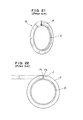
- the tire bead B is manufactured by sticking a filler rubber F, which is extrusion-molded to be triangular-shaped in cross section, to an outer peripheral surface of a ring-shaped bead core C as shown in FIG. 21
- the filler rubber F being triangular-shaped in cross section is extrusion-molded to be lengthy, and so it is general to stick the filler rubber to an outer peripheral surface of the bead core C to cut the same to a length corresponding to a single circumference of an outer periphery of the bead core C to join a leading end and a trailing end as cut.
- Patent Document 1 discloses a method of and an apparatus for supplying a lengthy filler rubber, which is extrusion-molded to be triangular-shaped in cross section, to a former, of which an outer peripheral surface is tapered and inclined, using a robot hand to move a trailing end, which is cut to a predetermined length, toward a leading end, positioning the trailing end and the leading end in an overlapping manner, and clamping the overlapped portions to join the same.
- the leading end and the trailing end are caused to overlap on the tapered, inclined surface of the former, and the overlapped portions are pushed against the inclined surface of the former to be joined together. Therefore, a surplus quantity of rubber is needed for the joining and the rubber bulges out even when forming is made after joining.
- the filler rubber is lengthened on an outer edge side to ensure a sufficient, circumferential length, there is caused a problem that overlap is increased on a base side (toward a core) of the filler rubber and degradation in weight balance is brought about.
- Patent Documents 2 and 3 disclose supplying a filler rubber, which is triangular-shaped in cross section, in a state of falling sidelong to stick the same to an outer peripheral surface of a bead core while rotating the bead core, when predetermined angle is rotated, cutting the filler rubber to a predetermined length, moving a leading end and a trailing end to a stationary plate, reversely rotating the bead core with the leading end pushed against the stationary plate, elongating a leading end side of the filler rubber, and joining the leading end and the trailing end.
- the filler rubber in a state of falling sidelong is stuck to the bead core and the ends are joined together, so that it is not easy to stand the filler rubber, which is put in a state of falling sidelong, in a radial direction after the joining and there is a fear of obstruction in conveyance to a tire molding process and tire molding. Besides, since the leading end and the trailing end are overlapped and joined, there is a fear that degradation in weight balance is brought about.
- Patent Document 1 JP-A-6-297603
- Patent Document 2 JP-A-8-142227
- Patent Document 3 JP-A-2003-127249
- the invention provides a method of and an apparatus for manufacturing a tire bead enabling efficiently and surely sticking a filler rubber, which is triangular-shaped in cross section, in an upright posture to an outer peripheral surface of a bead core, and in particular, enabling surely butting a leading end and a trailing end as cut without the generation of crack and hence enabling achieving an improvement in producibility of a tire bead.
- the invention solving the problems provides a method of manufacturing a tire bead formed by sticking a filler rubber in an upright posture, which is extrusion-molded to be triangular-shaped in cross section, to an outer peripheral surface of a ring-shaped bead core, the method comprising holding the filler rubber in an upright posture to wind the same around the outer peripheral surface of the ring-shaped bead core supported by a rotary support body keeping with rotation of the bead core, at the time of joining a leading end and a trailing end of the filler rubber cut to a length corresponding to a single circumference of the core outer periphery, having first interposing means and second interposing means interposing the neighborhood of the leading end and the neighborhood of the trailing end to oppose the leading end and the trailing end to each other on the outer peripheral surface of the bead core and displacing at least one of the interposing means toward the other from the opposed state to butt end surfaces of the leading end and the trailing end of the filler rubber against each other
- the first interposing means interposing the neighborhood of the leading end of the filler rubber interposes the leading end of the filler rubber, which is inclined rearward in a direction of rotation due to winding around the outer peripheral surface of the bead core, in a direction conformed to the inclination, displaces the leading end toward the other so as to elongate the same much as it goes toward an outer edge of the filler rubber, from a state of being opposed to the trailing end on an outer edge side with a spacing therebetween, and butting end surfaces of the leading end and the trailing end of the filler rubber against each other.
- no crack is generated on an outer edge side of a joint portion formed by butting the leading end and the trailing end against each other, joining can be made surely without the generation of an excessive overlapping and excessive bulging-out of rubber.
- the invention provides a method of manufacturing a tire bead formed by sticking a filler rubber in an upright posture, which is extrusion-molded to be triangular-shaped in cross section, to an outer peripheral surface of a ring-shaped bead core, the method comprising forwarding the filler rubber, which is supplied in a lengthy configuration, tangentially to a reference position, in which sticking to the outer peripheral surface of the bead core begins, in an upright posture in a state, in which the bead core is supported from inside by a rotary support body, having pinch rollers pushing both sides of a base of the filler rubber to stick the same to the outer peripheral surface of the bead core while winding is made keeping with rotation of the bead core by the rotary support body, when the leading end of the filler rubber reaches a position of a predetermined angle of rotation less than a single circumference from the reference position, stopping rotation by the rotary support body, having first interposing means interposing the neighborhood of the leading end, having second interposing means
- a filler rubber being triangular in cross section can be supplied to the outer peripheral surface of the bead core in an upright posture to be stuck thereto while being wound therearound, and end surfaces of the leading end and the trailing end can be butted against each other to be joined.
- the first interposing means interposing the neighborhood of the leading end of the filler rubber interposes the leading end of the filler rubber, which is inclined rearward in a direction of rotation due to winding around the outer peripheral surface of the bead core, in a direction conformed to the inclination, displaces the leading end toward the other so as to elongate the same much as it goes toward an outer edge of the filler rubber, from a state of being opposed to the trailing end on an outer edge side with a spacing therebetween, and butting end surfaces of the leading end and the trailing end of the filler rubber against each other.
- no crack is generated on an outer edge side of a joint portion and joining can be made surely without the generation of an excessive overlapping.
- the rotary support body it is preferable to stop rotation by the rotary support body when the leading end of the filler rubber reaches a position of an angle of rotation less than a single circumference but equal to or larger than 270° from the reference position, and to have the first interposing means interposing the neighborhood of the leading end of the filler rubber.
- the pinch rollers are caused to push both sides of a base of the filler rubber toward the trailing end keeping with rotation by the rotary support body to stick the same to the outer peripheral surface of the bead core, and the filler rubber including a joint portion formed by the butting is passed between a pair of interposing pressure rollers to be pinched from both sides to be reshaped.
- the joint portion formed by the butting can be reshaped to a predetermined thickness and joining can be made without the generation of excessive bulging-out of rubber.
- the bead core can comprise one formed by wrapping a fiber sheet on an outer periphery of a core body formed by winding a steel wire a plurality of turns.
- the invention provides a manufacturing apparatus used in carrying out the method of manufacturing a tire bead, the apparatus comprising a rotary support body that supports a ring-shaped bead core supplied one by one from an inner periphery thereof and can rotate, a feeding device that feeds the filler rubber, which is extrusion-molded to be triangular-shaped in cross section and supplied in a lengthy configuration, tangentially to a reference position, in which sticking to the outer peripheral surface of the bead core supported by the rotary support body begins, in an upright posture, a pair of pinch rollers that push both sides of a base of the filler rubber thus fed against the outer peripheral surface of the bead core in the reference position on the outer peripheral surface of the bead core to stick the same thereto keeping with rotation by the rotary support body, first interposing means that interposes the neighborhood of the leading end of the filler rubber stuck to the outer peripheral surface of the bead core from both sides when the leading end of the filler rubber reaches a position of a pre
- the leading end and the trailing end can be surely butted against each other to be joined while the bead core is rotated in a state of being supported on the rotary support body to hold the lengthy filler rubber, which is triangular-shaped in cross section, in an upright posture to stick the same to the outer peripheral surface of the bead core.
- the first interposing means interposing the neighborhood of the leading end of the filler rubber is provided to interpose the leading end of the filler rubber, which is inclined rearward in a direction of rotation due to winding around the outer peripheral surface of the bead core, in a direction conformed to the inclination and provided to be able to make a turning displacement about a fulcrum shaft in the vicinity of an inner periphery of the bead core to the other side so that the filler rubber is elongated much on an outer edge side thereof.
- joining can be surely accomplished without the generation of crack on an outer edge side of the joint portion.
- a sensor is provided to detect when the leading end of the filler rubber reaches a position of a predetermined angle of rotation less than a single circumference from the reference position, and rotation by the rotary support body is stopped on the basis of a detection signal of the leading end by the sensor.
- the first interposing means interposing the neighborhood of the leading end of the filler rubber is provided to be positioned in a position of a predetermined angle of rotation less than a single circumference but equal to or larger than 270° from the reference position and to perform an interposing motion to interpose the neighborhood of the leading end of the filler rubber when rotation by the rotary support body is stopped.
- the filler rubber is wound over an angle of rotation being close to a single circumference but equal to or larger than 270°, it is possible to move the trailing end of the filler rubber thus cut to a position opposed to the leading end to butt the same to join the same and to efficiently perform sticking of the filler rubber.
- a pair of interposing pressure rollers are provided a little forwardly in the rotational direction of the pinch rollers in the reference position to pressingly interpose the filler rubber including the joint portion from both sides.
- a pair of interposing pressure rollers are provided a little forwardly in the rotational direction of the pinch rollers in the reference position to pressingly interpose the filler rubber including the joint portion from both sides.
- a filler rubber which is extrusion-molded to be triangular-shaped in cross section, can be held in an upright posture on an outer peripheral surface of a bead core to be stuck thereto, and end surfaces of a leading end and a trailing end thus cut can be surely butted against each other to be joined.
- the bead thus manufactured involves no fear that crack is generated on a joint portion formed by the butting in handling until use in tire molding. Also, thereby, it is possible to improve a tire bead in manufacturing efficiency.
- FIG. 1 is a schematic, front view showing a bead manufacturing apparatus of the invention
- FIG. 2 is a schematic, plan view showing the bead manufacturing apparatus
- FIG. 3 is a schematic, front view showing a sticking device about a rotary support body
- FIG. 4 is a longitudinal, cross sectional view showing the rotary support body.
- FIG. 5 is a front view showing a feeding device of a filler rubber as viewed from laterally of a feeding direction
- FIG. 6 is a plan view showing the feeding device
- FIGS. 7 and 8 are cross sectional views taken along the line VII-VII and the line VIII-VIII in FIG. 6 , respectively.
- FIG. 9 is a side view showing a pressing roller
- FIG. 9 is a side view showing a pressing roller
- FIG. 10 is a view illustrating, in enlarged scale, a state, in which the filler rubber is pressed.
- FIG. 11 is a front view illustrating a state, in which first interposing means and second interposing means are supported,
- FIG. 12 is a side view showing a portion of the first interposing means,
- FIG. 13 is a plan view showing the portion of the first interposing means,
- FIG. 14 is a side view showing a portion of the second interposing means,
- FIG. 15 is a plan view showing the portion of the second interposing means, and
- FIG. 16 is a view illustrating a state, in which the filler rubber is butted and joined.
- FIG. 17 is a side view showing a portion of an interposing pressure roll, and
- FIG. 18 is a plan view showing the portion of the interposing pressure roll.
- the reference numeral 1 denotes a device that sticks a filler rubber F, in a bead manufacturing apparatus A according to the invention, 2 a supply unit for a ring-shaped bead core C, and 3 a supply unit for the filler rubber F.
- the bead core C is laminated and formed by winding a steel wire in a ring-shaped configuration to be made mainly rectangular (hexagonal and octagonal in cross section) in cross section.
- the bead core C comprises a bead core C formed by wrapping a meshy, thin fiber sheet S on a surface of a laminate of a wire W as shown in FIG. 19 .
- the bead cores C are engaged and conveyed one by one from the supply unit 2 by suitable conveyance means 4 and supplied to a rotary support body 10 , described later, of the sticking device 1 . Accordingly, the conveyance means 4 having the function of receiving the bead cores C one by one from the supply unit 2 and forwarding a single bead core C as received forwardly of the rotary support body to deliver the same to the rotary support body 10 .
- the filler rubber F is in the form of a band being triangular-shaped in cross section, in particular, longitudinally triangular-shaped in cross section to correspond to a bead being manufactured, and ordinarily extrusion-molded continuously from an extruder 5 provided on the supply unit 3 to be supplied to a portion of a feeding device 20 contiguous to the sticking device 1 through a running guide section 7 provided with a festoon device 6 and a plurality of guide rollers.
- the filler rubber F extrusion-molded in a state of falling sidelong is gradually varied in posture in the running guide section 7 to be supplied in a substantially upright posture to a portion of the feeding device 20 .
- the ring-shaped bead cores C supplied one by one by the conveyance means 4 conforming to a sticking cycle of the filler rubber F are supported from inside by the rotary support body 10 provided on the sticking device 1 .
- the rotary support body 10 has the following construction.
- the rotary support body 10 comprises mount plates 12 arranged about a hollow rotating shaft 11 and formed by dividing a doughnut-shaped disk into four sections, and arucate support portions 13 mounted along outer peripheries of the respective mount plates 12 , and grooves 13 a having a U-shaped cross section and having an inner peripheral side of the bead core C fitted thereinto are formed on an outer sides of the support portions 13 , so that the inner peripheral side of the bead core C can be supported from inside in a state of being fitted into the grooves 13 a.
- the respective mount plates 12 are supported so that guide portions 12 a provided on back sides thereof engage radially slidably with and do not separate from radial guide members 11 b provided on front surfaces of flanged mount plates 11 a provided on a forward end of the rotating shaft 11 , the respective mount plates being provided to be connected to an operating shaft 14 , which is provided axially slidably in an inner hole of the rotating shaft 11 , through a link member 15 and to radially expand or contract owing to an advance and retreat action of the operating shaft 14 .
- the support portions 13 can suitably engage with and disengage from the bead core C to conform to a change in inside diameter of the bead core C.
- the reference numeral 16 denotes a cylinder device that advances and retreats the operating shaft 14 , 17 a drive motor connected to the rotating shaft 11 through rotation transmitting means 18 such as belt or the like, and the motor 17 is rotationally driven to enable the rotary support body 10 .
- a support frame 19 rotatably supporting the rotary support body 10 is provided to enable moving up and down relative to a device frame 8 by advance or retreat means such as cylinder device or the like, or lift means such as jack or the like (not shown), and the support frame 19 moves up and down to enable adjusting the height of the rotary support body 10 corresponding to a bead diameter of an object being manufactured.
- the drive motor 17 is mounted to and supported on the support frame 19 of the rotary support body 10 .
- the feeding device 20 for the filler rubber F has the following construction so that a support frame 21 of the device is engaged and supported to be movable relative to a frame 9 arranged in parallel to a feeding direction of the filler rubber F through a linear guide 22 extending in a longitudinal direction (feeding direction) of the frame.
- a feed base 23 is provided to enable putting thereon the filler rubber F, which is supplied in an upright posture via the running guide section 7 , to forward the same in the feeding direction.
- the feed base 23 is provided to comprise guide plates 24 , 24 provided upright on an upper surface of a plate frame 23 a on both sides of a spacing, through which the filler rubber F can pass, and an endless belt 23 b arranged between the both guide plates 24 , 24 to slide on the plate frame 23 a and revolve in the feeding direction, and the belt 23 b revolves to enable forwarding the filler rubber F at a constant speed.
- the feed base 23 is engaged by and connected to the support frame 21 through a linear guide 25 and a rack mechanism 26 , which extend in the direction of movement, and supported to be maintained horizontal, the feed base being provided to move together with the support frame 21 .
- a pair of interposing members 27 , 27 are provided to enable interposing the filler rubber F from both sides through cut windows 24 a , 24 a , which are provided on the guide plates 24 , 24 to extend longitudinally.
- the interposing members 27 , 27 are mounted to and supported on a bracket 29 through an air chuck mechanism 28 and provided to be actuated by the air chuck mechanism 28 to perform an interposing motion when it is necessary to cut the filler rubber and to forward a leading end thereof.
- the bracket 29 is engaged, connected, and supported to be movable relative to the support frame 21 through a linear guide 30 .
- the reference numeral 31 denotes a cylinder device mounted to the frame 9 and connected to the support frame 21 , and the whole of the feeding device 20 on the support frame 21 is caused upon actuation of the cylinder device 31 to advance and retreat in the feeding direction of the filler rubber F.
- the reference numeral 32 denotes a cylinder device mounted to the support frame 21 and connected to the bracket 29 , and the bracket 29 supporting the interposing members 27 , 27 are caused upon actuation of the cylinder device 32 to advance toward and retreat from the support frame 21 in the feeding direction.
- the reference numeral 33 denotes a drive transmission shaft of the belt 23 b , and the drive transmission shaft 33 is connected to a drive motor 37 through a timing belt 36 stretched round timing pulleys 34 , 35 .
- Push means 39 is provided to interpose between it and a belt receiver 38 when the support frame 21 and the bracket 29 are to be moved, thereby agreeing timing, in which the support frame 21 and the bracket 29 move, with timing of forwarding of the belt 23 b.
- the cylinder devices 31 , 32 actuate to move the support frame 21 and the bracket 29 whereby a leading end of F 1 of the filler rubber F interposed between the both guide plates 24 , 24 on the feed base 23 by the interposing members 27 , 27 is forwarded to a reference position P 1 , in which sticking to an outer peripheral surface of the bead core C supported on the rotary support body 10 begins, and to a reference position P 1 , in the case shown in the figure, set on a topmost portion of the bead core C supported in the manner described above.
- setting is such that the support frame 21 is first moved to advance the whole including the feed base 23 and the interposing members 27 , 27 and then the bracket 29 is advanced and moved relative to the support frame 21 to advance the interposing members 27 , whereby the leading end F 1 of the filler rubber F by the interposing members 27 , 27 is forwarded to a reference position P 1 on an outer periphery of the bead core C on the rotary support body 10 .
- the interposing motions of the interposing members 27 , 27 are released and return to an original position is accomplished.
- a pinch roller unit 40 including a pair of vertically movable pinch rollers 40 a , 40 b , by which both sides of a base of the filler rubber F thus forwarded are pushed against and stuck to the outer peripheral surface of the bead core C in conformity to rotation by the rotary support body 10 .
- the pinch rollers 40 a , 40 b are pivotally supported to be able to turn by mount members 42 , 42 such that respective disk-shaped roller plates 41 , 41 are spaced to enable entering of the interposing members 27 , 27 put in a state of interposing the filler rubber F fore and aft as viewed from the front of the rotary support body 10 and inclined to be decreased in spacing toward a lower end side opposed to the bead core C on the support portions 13 of the rotary support body 10 .
- the mount members 42 , 42 are mounted to support members 44 , 44 , of which spacing can be adjusted by rotation of a screw shaft 43 , to be angularly adjustable and supported to enable adjusting the roller plates 41 , 41 in angle of inclination and spacing.
- lower ends of the both roller plates 41 , 41 can be adjusted in angle of inclination and spacing according to the thickness of the filler rubber F and the width of the bead core C, so that both sides of the base of the filler rubber F can be pushed against and pressed to the bead core C as shown in FIG. 10 .
- the reference numeral 46 denotes a linear guide that supports the support members 44 , 44 to make the same slidable relative to a support bracket 45 for lifting.
- the support bracket 45 is supported on the longitudinal device frame 8 through a linear guide 47 to able to go up and down, and a cylinder device 48 for lifting is connected to an upper portion of the support bracket 45 , so that the cylinder device 48 is actuated to have the support bracket 45 going up and down whereby the pinch rollers 40 a , 40 b go up and down between a position of pressing the both sides of the base of the filler rubber F and a position of retreating above a position, to which the filler rubber F is forwarded. Thereby, it is possible to retreat the pinch rollers 40 a , 40 b upward as indicated by chain lines when the bead core C is to be set and when a bead completed after the filler rubber F is stuck thereto is to be taken out.
- first interposing means 50 that interposes the neighborhood of the leading end of the filler rubber F stuck to the outer peripheral surface of the bead core C and second interposing means 70 that interposes the neighborhood of the trailing end of the filler rubber F being cut to a predetermined length corresponding to a single circumference of the outer periphery of the bead core are provided around the rotary support body 10 as shown in FIG. 11 .
- the second interposing means 70 is constructed to enable the cut trailing end F 2 of the filler rubber F to a position (position indicated by chain lines in FIG.
- the first interposing means 50 is constructed to be able to be displaced toward the second interposing means 70 opposed thereto (chain lines in FIG. 11 ).
- the first interposing means 50 and the second interposing means 70 are constructed to make an interposing motion when rotation by the rotary support body 10 is stopped. Therefore, a sensor 51 is provided in the vicinity of the first interposing means 50 to detect the leading end F 1 of the filler rubber F reaches a position of the predetermined angle of rotation from the reference position P 1 , and rotation of the rotary support body 10 caused by the drive motor 17 is stopped on the basis of a detection signal of the leading end F 1 by the sensor 51 .
- the first interposing means 50 and the second interposing means 70 are constructed to make an interposing motion simultaneously with the stoppage of rotation.
- the second interposing means 70 is controlled to move the trailing end F 2 to a position opposed to the leading end F 1 on the bead core C after a cutting device 80 described later cuts the trailing end F 2 in the interposed state
- the first interposing means 50 is controlled to move toward the second interposing means 70 after the movement of the second interposing means 70 after the neighborhood of the leading end F 1 is interposed.
- the first interposing means 50 is provided to be positioned in a position of a predetermined angle of rotation less than a single circumference from the reference position P 1 in a direction, in which the rotary support body 10 rotates for winding of a filler rubber, preferably, a position of an angle of rotation exceeding 270° but less than a single circumference from the reference position P 1 , in particular, preferably, in a position of an angle of rotation in the range of 270° to 315° and to interpose the neighborhood of the leading end F 1 with some length (preferably, around 5 to 15 mm) of the leading end F 1 of the filler rubber F left in a protrusive manner from both sides.
- the first interposing means 50 includes a pair of interposing members 50 a , 50 b , which can open and close, and is constructed in the following manner.
- a base plate 53 journaled by a journal shaft 52 on the device frame 8 is provided rearwardly of a position, in which the bead core C is supported by the rotary support body 10 .
- a swing arm 55 is mounted to a fulcrum shaft 54 set on the base plate 53 in a position in the vicinity inside the bead core C to be able to turn and one of the pair of interposing members 50 a , 50 b , for example, the interposing member 50 a is mounted to a mount plate 56 projecting forwardly of the swing arm 55 to be parallel to the filler rubber F stuck to the bead core C in an upright posture.
- the other 50 b of the interposing members is pivotally connected to the one 50 a of the interposing members to be able to turn, a rack 59 advanced and retreated by a cylinder device 58 meshes with a pinion 57 provided integral with the interposing member 50 b , and the rack 59 advances or retreats whereby the interposing member 50 b turns in a direction, in which it opens or closes relative to the one 50 a of the interposing members, to interpose the filler rubber F between it and the one 50 a of the interposing members.
- the other 50 b of the interposing members is held outside the filler rubber F except at the time of interposing motion to enable the work of setting the bead core C on the rotary support body 10 and taking out the bead.
- the reference numeral 60 in the figure denotes a guide roller that feeds the filler rubber F into between the both interposing members 50 a , 50 b.
- the interposing members 50 a , 50 b are provided as shown in the figure to be inclined to the outer peripheral surface of the bead core C rearward in the direction of rotation as they go outward, taking into consideration inclination of the leading end F 1 of the filler rubber F wound round the outer peripheral surface of the bead core C. That is, as the rotary support body 10 rotates, an outer edge side of the filler rubber F being wound round the outer peripheral surface of the bead core C is pulled rearward in the direction of rotation as it goes toward an outer edge, so that the leading end F 1 is put in a state of being inclined to the core outer peripheral surface rearward in the direction of rotation. Therefore, taking into consideration inclination of the leading end F 1 of the filler rubber F, the interposing members 50 a , 50 b are provided to enable interposing the filler rubber F in a direction corresponding to inclination thereof.
- a cylinder device 61 is connected to the swing arm 55 supporting the interposing members 50 a , 50 b and the cylinder device 61 is actuated to turn the swing arm 55 about the fulcrum shaft 54 whereby the interposing members 50 a , 50 b are turned about the fulcrum shaft 54 to be displaced.
- leading end F 1 of the filler rubber F is elongated much as it goes toward an outer edge thereof, from a state of being inclined to the outer peripheral surface of the bead core C rearward in the direction of rotation, and can be put in a state of being made substantially perpendicular to the core outer peripheral surface in a position, in which it is butted against the trailing end F 2 described later, as indicated by chain lines in FIG. 11 and as shown in FIG. 16 .
- the base plate 53 is supported to be enabled by actuation of a cylinder device 62 connected to a lower end thereof to turn about the journal shaft 52 and provided to thereby enable adjusting a position, in which the base plate 53 is supported, and hence a position of the first interposing means 50 on the base plate 53 , a position of the fulcrum shaft 54 of the swing arm 55 , a position of the sensor 51 , etc. according to a size (diameter) of the bead core C supported on the rotary support body 10 .
- the second interposing means 70 is provided to interpose the neighborhood of the trailing end F 2 from both sides, which is cut to a predetermined length corresponding to a single circumference of the outer periphery of the bead core, in a position forwardly of the feeding device 20 in a forwarding direction and on this side of the reference position P 1 with some length (preferably, around 5 to 15 mm) of the trailing end F 2 of the filler rubber F left in a protrusive manner. That is, when cut by the cutting device 80 described later, the trailing end F 2 is interposed such that some length thereof projects.
- the second interposing means 70 comprises a pair of interposing members 70 a , 70 b and one 70 a of the interposing members is arranged vertically along a side of the filler rubber F forwarded to the reference position P 1 from the feeding device 20 in the manner described above.
- the other 70 b of the interposing members is pivotally connected to the one 70 a of the interposing members above the filler rubber F as forwarded to be able to turn, a rack 73 advanced and retreated by a cylinder device 72 meshes with a pinion 71 provided integral with the interposing member 70 b , and the rack 73 advances or retreats whereby the interposing member 70 b turns in a direction, in which it opens or closes relative to the one 70 a of the interposing members, to interpose the filler rubber F between it and the one 70 a of the interposing members.
- the one 70 a of the interposing members is connected to and supported on the journal shaft 52 through an arm member 74 , and provided to turn about the journal shaft 52 in a state, in which the both interposing member 70 a , 70 b interpose the trailing end F 2 , to thereby move to a position opposed to the leading end F 1 stuck to the bead core C on the rotary support body 10 (chain lines in FIG. 11 ).
- journal shaft 52 supporting the arm member 74 is connected at a radial projection thereof to a cylinder device 75 rearwardly of the base plate 53 and as the cylinder device 75 is actuated to rotate the journal shaft 52 , the arm member 74 turns to move the both interposing members 70 a , 70 b to the opposed position on the bead core C from a position, in which the interposing members make an interposing motion.
- the cutting device 80 is provided above a side toward the feeding device 20 relative to a position, in which the interposing members 70 a , 70 b make an interposing motion, to cut the filler rubber F as forwarded.
- a cutter blade 81 of the cutting device 80 is normally held above the filler rubber F as forwarded not to get in the way of forwarding of the filler rubber F by the feeding device 20 , and after the second interposing means 70 makes an interposing motion, the cutter blade 81 descends owing to actuation of a cylinder device or the like whereby the filler rubber F is cut.
- a position, in which the cutting device 80 makes a cut is set so that a length to the cut position from the reference position P 1 , in which sticking to the bead core C supported on the rotary support body begins, corresponds substantially to a distance to the reference position P 1 on the outer periphery of the bead core C from the leading end F 1 of the filler rubber F interposed by the first interposing means 50 , or a distance to the reference position from a position, in which the leading end and the trailing end are butted against each other on the outer periphery of the bead core.
- an interposing pressure roller unit 90 including a pair of interposing pressure rollers 90 a , 90 b that pressingly interpose and reshape the filler rubber F stuck to the outer peripheral surface of the bead core C from both sides is provided a little forwardly of the pinch rollers 40 a , 40 b in the direction of rotation.
- One of the interposing pressure rollers 90 a , 90 b that is, the interposing pressure roller 90 a positioned on a back side of the filler rubber F as viewed from the front of the apparatus (the front of the rotary support body) is supported by a support shaft 92 , which is mounted to a bracket 91 mounted to the device frame 8 along a side on the back side of the filler rubber F, in a direction perpendicular to the outer peripheral surface of the bead core to be able to rotate.
- a roller body 93 of the interposing pressure roller 90 a is provided on the support shaft 92 with an eccentric cam roller 94 therebetween and supported to be able to approach or separate from the side of the filler rubber F upon rotation of the cam roller 94 , the roller body being disposed separate from the filler rubber F except at the time of action of interposing pressure ( FIG. 18 ).
- the reference numeral 95 denotes a cylinder device connected to the cam roller 94 , and the cam roller 94 is rotated by actuation of the cylinder device 95 .
- a shaft portion 97 of the other 90 b of the interposing pressure rollers is mounted to an arm 96 , which is pivotally supported by the bracket 91 to be able to turn, the arm 96 is provided to be able to open or close relative to the one 90 a of the interposing pressure rollers upon actuation of a cylinder device 98 connected thereto, when the filler rubber is to be stuck, the interposing pressure roller 90 b is positioned in a position in opposed contact with the side of the filler rubber F (a state indicated by solid lines in FIG. 17 ), and when the bead core is to be set and when a bead completed after the filler rubber F is stuck thereto is to be taken out, the interposing pressure roller can be put in a state indicated by chain lines in FIG. 17 .
- guide rollers are arranged at need at suitable intervals around the rotary support body 10 to inhibit fall of the filler rubber F stuck to the bead core C in an upright posture (not shown).
- a filler rubber F which is extrusion-molded from the extruder 5 to be triangular-shaped in cross section, is fed to a portion of the feeding device 20 contiguous to the sticking device 1 while passing through the air-cooled festoon device 6 to be gradually put in an upright posture.
- a ring-shaped bead core C is fed forwardly of the sticking device 1 from the bead core supply unit 2 by the conveyance means 4 , which can hold the bead core C in a latched state to convey the same, and fed to the rotary support body 10 of the sticking device 1 from the conveyance means 4 to be engaged from inside and supported by the support portions 13 provided on the rotary support body 10 .
- the filler rubber F fed to the feeding device 20 to be interposed by the guide plates 24 , 24 on both sides thereof is interposed by the interposing members 27 , 27 on the portions of the cut windows 24 a of the guide plates 24 , 24 to stand by.
- the cylinder device 31 is actuated to advance the support frame 21 of the feeding device 20 toward the reference position P 1 , in which sticking to the bead core C supported on the rotary support body begins.
- Such advance causes the guide plates 24 and the interposing members 27 , 27 to approach the reference position P 1 and the bracket 29 supporting the interposing members 27 , 27 is advanced, whereby the leading end F 1 of the filler rubber F in an upright posture is forwarded to the reference position P 1 on a top of the outer peripheral surface of the bead core C supported on the rotary support body 10 ( FIG. 20B ) and the interposing action of the interposing members 27 is released simultaneously with such forwarding.
- the pinch roller unit 40 including the pair of pinch rollers 40 a , 40 b descends to be positioned in the reference position P 1 , that is, a pinch position, in which it abuts on the bead core C, so that simultaneously when the leading end F 1 of the filler rubber F is forwarded, the pinch rollers 40 a , 40 b cause both sides of the base thereof to come into pressure contact with and stick to the bead core C.
- the cutting device 80 and the second interposing means 70 that interposes the neighborhood of the trailing end F 2 being cut retreat to upper or rearward positions, in which they do not obstruct advancing of the feeding device 20 and forwarding of the filler rubber F.
- both sides of the base are caused by the pinch rollers 40 a , 40 b to come into pressure contact with and stick to the bead core C while held in an upright posture to be wound around the outer peripheral surface of the bead core C supported on the outer periphery of the rotary support body 10 ( FIG. 20C ).
- the feeding device 20 and the interposing members 27 return to original positions.
- the sensor 51 detects this matter and rotation of the leading end F 1 is stopped in a position slightly forwardly of a position, in which the leading end F 1 is interposed by the first interposing means 50 .
- the cylinder device 59 of the first interposing means 50 actuates to perform an interposing action and the both interposing members 50 a , 50 b interpose the neighborhood of the leading end F 1 from both sides ( FIG. 20D ).
- the first interposing means 50 interposes the leading end F 1 , which is inclined to the outer peripheral surface of the core rearward in the direction of rotation, in a direction corresponding to inclination thereof.
- the feeding device 20 and the interposing members 27 , 27 respectively, having been positioned in advanced positions return to original positions.
- the second interposing means 70 is moved to a position close to the filler rubber F and actuated by the cylinder device 72 perform an interposing action, and so the interposing members 70 a , 70 b interpose the neighborhood of a portion, which makes the trailing end F 2 formed by cutting the filler rubber F.
- the interposing members 27 , 27 on the feeding device 20 are operated again to interpose the filler rubber F between the both guide plates 24 , 24 .
- the cutter blade 81 of the cutting device 80 descends to cut the filler rubber F, which is interposed by the second interposing means 70 , in a location of a length corresponding to a single circumference of the outer periphery of the core from the leading end F 1 ( FIG. 20E ).
- the second interposing means 70 in a state of interposing the neighborhood of the trailing end F 2 of the filler rubber F being cut is caused by turning of the arm member 74 by actuation of the cylinder device 75 to move to a position opposed to the leading end F 1 on the bead core C from the interposing position.
- the trailing end F 2 is moved to be made substantially perpendicular to the core outer peripheral surface in a manner to elongate an outer edge side of the filler rubber F.
- leading end F 1 and the trailing end F 2 of the filler rubber F are opposed to each other in a state of projecting a little from the first interposing means 50 and the second interposing means 70 on the outer periphery of the bead core C (chain lines in FIG. 20E ).
- the cylinder device 61 is actuated to turn the swing arm 55 to turn and displace the first interposing means 50 toward the second interposing means 70 , in keeping with which, the filler rubber F is elongated much as it goes toward an outer edge thereof and the leading end F 1 is put in a state of being made substantially perpendicular to the outer periphery of the bead core C from a state of being inclined to the outer peripheral surface of the bead core C rearward in the direction of rotation, and thus butted against the trailing end F 2 interposed by the second interposing means 70 , with the result that the leading end F 1 and the trailing end F 2 are joined ( FIG. 20F ).
- the rotary support body 10 again rotates to cause the pinch rollers 40 a , 40 b to push both sides of the base of the filler rubber F toward the trailing end F 2 to stick the same to the outer peripheral surface of the bead core C and the filler rubber F including a joint portion J formed by the butting is passed between the pair of interposing pressure rollers 90 a , 90 b to be pinched from both sides to be reshaped. Thereby, the joint portion J formed by the butting can be reshaped to a predetermined thickness.
- the leading end F 1 and the trailing end F 2 can be butted against each other to be surely joined without an excessive overlapping and shortage of rubber, while the filler rubber F in an upright posture is forwarded to the outer peripheral surface of the bead core C to be wound therearound and stuck thereto as it is in an upright posture, a bead B with the filler rubber F stuck to the bead core C can be efficiently manufactured, and manufacture of a bead can be automated.
- a method of and an apparatus for manufacturing a tire bead can be preferably made use of in sticking a filler rubber, which is extrusion-molded to be triangular-shaped in cross section, to an outer peripheral surface of a bead core, around which wire is wound in a ring-shaped configuration and which is subjected to laminate molding to be made rectangular in cross section, in a state of being held in an upright posture to the outer peripheral surface to manufacture a bead.
- FIG. 1 is a schematic, front view showing a bead manufacturing apparatus of the invention.
- FIG. 2 is a schematic, plan view showing the bead manufacturing apparatus.
- FIG. 3 is a schematic, front view showing a sticking device about a rotary support body.
- FIG. 4 is a longitudinal, cross sectional view showing the rotary support body.
- FIG. 5 is a front view showing a feeding device of a filler rubber as viewed from laterally of a feeding direction.
- FIG. 6 is a plan view showing the feeding device.
- FIG. 7 is a cross sectional view taken along the line VII-VII in FIG. 6 .
- FIG. 8 is a cross sectional view taken along the line VIII-VIII in FIG. 6 .
- FIG. 9 is a side view showing a pressing roller.
- FIG. 10 is a view illustrating, in partly enlarged scale, a state, in which the filler rubber is pressed.
- FIG. 11 is a front view illustrating a state, in which first interposing means and second interposing means are supported.
- FIG. 12 is a side view showing a portion of the first interposing means.
- FIG. 13 is a plan view showing the portion of the first interposing means.
- FIG. 14 is a side view showing a portion of the second interposing means.
- FIG. 15 is a plan view showing the portion of the second interposing means.
- FIG. 16 is a illustrating a state, in which the filler rubber is butted and joined.
- FIG. 17 is a side view showing a portion of an interposing pressure roll.
- FIG. 18 is a plan view showing the portion of the interposing pressure roll.
- FIG. 19 is a cross sectional view showing an example of a bead core.
- FIG. 20A is a view illustrating a state, in which the filler rubber is stuck to the bead core.
- FIG. 20B is a view illustrating a state, in which the filler rubber is stuck to the bead core.
- FIG. 20C is a view illustrating a state, in which the filler rubber is stuck to the bead core.
- FIG. 20D is a view illustrating a state, in which the filler rubber is stuck to the bead core.
- FIG. 20E is a view illustrating a state, in which the filler rubber is stuck to the bead core.
- FIG. 20F is a view illustrating a state, in which the filler rubber is stuck to the bead core.
- FIG. 20G is a view illustrating a state, in which the filler rubber is stuck to the bead core.
- FIG. 21 is a perspective view showing a tire bead with a portion thereof cut.
- FIG. 22 is a view illustrating a state, in which a filler rubber is wound round a bead core of a tire bead.
- B tire bead
- C bead core
- F filler rubber
- F 1 leading end of filler rubber
- F 2 trailing end of filler rubber
- J joint portion
- P 1 reference position
- W wire
- 1 sticking device
- 2 supply unit of bead core
- 3 supply unit of filler rubber
- 4 conveyance means
- 5 extruder
- 6 festoon device
- 7 running guide section
- 8 device frame
- 9 horizontal frame
- 10 rotary support body
- 11 hollow rotating shaft
- 11 a flanged mount plate
- 11 b guide member
- 12 mount plate
- 12 a guide portion
- 13 a grooves
- 13 support member
- 14 operating shaft
- 15 link member
- 16 cylinder device
- 17 drive motor
- 18 rotation transmitting means
- 19 support frame
- 20 feeding device
- 21 support frame
- 22 linear guide
- 23 feeding base
- 23 feeding base
Priority Applications (1)
| Application Number | Priority Date | Filing Date | Title |
|---|---|---|---|
| US13/236,727 US8857489B2 (en) | 2006-07-21 | 2011-09-20 | Method of and apparatus for manufacturing a tire bead |
Applications Claiming Priority (1)
| Application Number | Priority Date | Filing Date | Title |
|---|---|---|---|
| PCT/JP2006/314473 WO2008010293A1 (en) | 2006-07-21 | 2006-07-21 | Method and device for producing tire bead |
Related Child Applications (1)
| Application Number | Title | Priority Date | Filing Date |
|---|---|---|---|
| US13/236,727 Division US8857489B2 (en) | 2006-07-21 | 2011-09-20 | Method of and apparatus for manufacturing a tire bead |
Publications (2)
| Publication Number | Publication Date |
|---|---|
| US20090266474A1 US20090266474A1 (en) | 2009-10-29 |
| US9138952B2 true US9138952B2 (en) | 2015-09-22 |
Family
ID=38956629
Family Applications (2)
| Application Number | Title | Priority Date | Filing Date |
|---|---|---|---|
| US12/374,023 Active 2027-12-17 US9138952B2 (en) | 2006-07-21 | 2006-07-21 | Method of and apparatus for manufacturing a tire bead |
| US13/236,727 Active US8857489B2 (en) | 2006-07-21 | 2011-09-20 | Method of and apparatus for manufacturing a tire bead |
Family Applications After (1)
| Application Number | Title | Priority Date | Filing Date |
|---|---|---|---|
| US13/236,727 Active US8857489B2 (en) | 2006-07-21 | 2011-09-20 | Method of and apparatus for manufacturing a tire bead |
Country Status (4)
| Country | Link |
|---|---|
| US (2) | US9138952B2 (ja) |
| JP (1) | JP4746100B2 (ja) |
| DE (1) | DE112006003959B4 (ja) |
| WO (1) | WO2008010293A1 (ja) |
Families Citing this family (26)
| Publication number | Priority date | Publication date | Assignee | Title |
|---|---|---|---|---|
| DE102007018971B4 (de) | 2007-04-21 | 2018-09-13 | Continental Reifen Deutschland Gmbh | Vorrichtung zum automatischen Herstellen von Wulstkernpaketen |
| JP5749919B2 (ja) * | 2010-11-19 | 2015-07-15 | 住友精密工業株式会社 | 6方向指向装置 |
| US20120318440A1 (en) * | 2011-06-14 | 2012-12-20 | Richard David Vargo | Method and apparatus for forming an annular elastomeric tire component |
| JP6065255B2 (ja) * | 2012-01-27 | 2017-01-25 | 株式会社ブリヂストン | タイヤ用ビード部材の製造方法、製造装置およびタイヤ用ビード部材 |
| RU2601523C2 (ru) * | 2012-04-26 | 2016-11-10 | Фудзи Сейко Ко., Лтд. | Устройство для намотки бортового кольца |
| NL2008819C2 (en) | 2012-05-15 | 2013-11-18 | Vmi Holland Bv | Positioning device for use in a tire building system and a method for positioning a bead. |
| JP5580849B2 (ja) | 2012-05-16 | 2014-08-27 | 住友ゴム工業株式会社 | ビードエーペックスゴム形成方法、及びそれに用いるビードエーペックスゴム形成装置 |
| NL2009946C2 (en) * | 2012-12-10 | 2014-06-11 | Vmi Holland Bv | Tyre building machine for forming a bead-apex assembly. |
| US8955571B2 (en) * | 2012-12-12 | 2015-02-17 | The Goodyear Tire & Rubber Company | Apparatus for supporting and holding a bead core-apex subassembly and method of producing and transporting the bead core-apex subassembly |
| CN104918777B (zh) * | 2013-01-17 | 2017-11-28 | 不二精工株式会社 | 胎圈成形设备和成形方法 |
| NL2010201C2 (en) * | 2013-01-30 | 2014-08-04 | Vmi Holland Bv | Apparatus for forming an annular apex filler. |
| KR102059600B1 (ko) * | 2013-10-03 | 2019-12-26 | 후지 세이코 가부시키가이샤 | 비드 코어에 대한 필러의 장착 방법 및 장착 장치 |
| ES2766263T3 (es) * | 2013-10-18 | 2020-06-12 | Bartell Mach Sys Llc | Sistema y método para agarrar y manipular un ápice de talón de neumático |
| RU2661989C2 (ru) * | 2014-03-24 | 2018-07-23 | Фудзи Сейко Ко., Лтд. | Способ намотки и устройство для намотки наполнительного шнура борта для шины |
| NL2013314B1 (en) * | 2014-08-08 | 2016-09-21 | Vmi Holland Bv | Stretching device for an apex filler strip and apex handling system comprising the stretching device. |
| DE102014113795A1 (de) * | 2014-09-24 | 2016-03-24 | Sma Solar Technology Ag | Verfahren zur Integration eines Wechselrichters in ein drahtloses lokales Kommunikationsnetzwerk und dazu geeigneter Wechselrichter |
| US10456807B2 (en) * | 2014-11-25 | 2019-10-29 | Bartell Machinery Systems, L.L.C. | Bead-apex assembly systems |
| JP6242460B1 (ja) * | 2016-10-28 | 2017-12-06 | 中田エンヂニアリング株式会社 | ビードエーペックスゴム形成方法、及びビードエーペックスゴム形成装置 |
| CN106393758B (zh) * | 2016-11-17 | 2018-07-03 | 杭州朝阳橡胶有限公司 | 一种轮胎成型机外侧胎圈预置装置 |
| CN106393756B (zh) * | 2016-11-17 | 2018-07-03 | 杭州朝阳橡胶有限公司 | 一种全钢子午线轮胎的三鼓成型机 |
| JP6872377B2 (ja) * | 2017-01-27 | 2021-05-19 | 株式会社ブリヂストン | フィラー付きビードの製造方法および装置 |
| WO2019118273A1 (en) * | 2017-12-14 | 2019-06-20 | Bartell Machinery Systems, L.L.C. | Self adjusting stitching wheel and method for adjusting the height of a stitching wheel |
| FR3083477B1 (fr) * | 2018-05-14 | 2020-06-19 | Compagnie Generale Des Etablissements Michelin | Procede de fabrication d'une tringle tressee pour bandage pneumatique, avec pliage d'un troncon excedentaire du fil de tresse |
| JP7413817B2 (ja) | 2020-02-14 | 2024-01-16 | 住友ゴム工業株式会社 | エイペックスの貼付装置及び貼付方法 |
| JP7413818B2 (ja) | 2020-02-14 | 2024-01-16 | 住友ゴム工業株式会社 | エイペックスの貼付装置及び貼付方法 |
| NL2027901B1 (en) * | 2021-04-01 | 2022-10-17 | Vmi Holland Bv | Method for positioning a strip for splicing, gripper for supplying said strip for splicing and tire building machine comprising said gripper |
Citations (14)
| Publication number | Priority date | Publication date | Assignee | Title |
|---|---|---|---|---|
| JPS5488979A (en) | 1977-12-15 | 1979-07-14 | Pirelli | Apparatus for automatically feeding elastomer filler to tire bead core |
| US4226663A (en) * | 1977-12-15 | 1980-10-07 | Industrie Pirelli, S.P.A. | Apparatus for associating a bead filler with a bead core of a vehicle tire |
| US4354892A (en) * | 1979-10-09 | 1982-10-19 | Societa Pneumatici Pirelli S.P.A. | Apparatuses for applying elastomeric fillers to tire bead-cores |
| JPS6490736A (en) | 1987-09-30 | 1989-04-07 | Sumitomo Rubber Ind | Apex mounting and its device |
| JPH0220331A (ja) | 1988-05-18 | 1990-01-23 | Pirelli Coordinamento Pneumatici Spa | フイラー端部をスプライスする装置 |
| US4990212A (en) * | 1988-06-08 | 1991-02-05 | Pirelli Coordinamento Pneumatici S.P.A. | Device for applying an elastomeric filler on the bead core of a pneumatic tire |
| US5328533A (en) * | 1990-02-15 | 1994-07-12 | Sumitomo Rubber Industries, Ltd. | Bead apex applying method and device |
| JPH06297603A (ja) | 1993-04-16 | 1994-10-25 | Bridgestone Corp | ビードフィラのビードワイヤへの貼付方法およびその装置 |
| JPH08142227A (ja) | 1994-11-22 | 1996-06-04 | Bridgestone Corp | フィラー貼付方法および装置 |
| US5735995A (en) * | 1996-02-13 | 1998-04-07 | The Steelastic Company, L.L.C. | Apparatus for applying an apex filler to a bead ring |
| JPH10291261A (ja) | 1997-04-21 | 1998-11-04 | Sumitomo Rubber Ind Ltd | ビードエイペックスジョイント装置 |
| JP2002096401A (ja) | 2000-09-25 | 2002-04-02 | Yokohama Rubber Co Ltd:The | ビードフィラーの圧着方法及びその装置 |
| JP2003127249A (ja) | 2001-10-25 | 2003-05-08 | Bridgestone Corp | ビードコアへのフィラーの貼付け方法および装置 |
| US20060102270A1 (en) * | 2004-11-12 | 2006-05-18 | Sumitomo Rubber Industries, Ltd. | Pneumatic tire |
-
2006
- 2006-07-21 DE DE112006003959.8T patent/DE112006003959B4/de active Active
- 2006-07-21 US US12/374,023 patent/US9138952B2/en active Active
- 2006-07-21 JP JP2008525771A patent/JP4746100B2/ja active Active
- 2006-07-21 WO PCT/JP2006/314473 patent/WO2008010293A1/ja active Application Filing
-
2011
- 2011-09-20 US US13/236,727 patent/US8857489B2/en active Active
Patent Citations (17)
| Publication number | Priority date | Publication date | Assignee | Title |
|---|---|---|---|---|
| US4226663A (en) * | 1977-12-15 | 1980-10-07 | Industrie Pirelli, S.P.A. | Apparatus for associating a bead filler with a bead core of a vehicle tire |
| GB1597199A (en) | 1977-12-15 | 1981-09-03 | Pirelli | Device for the application of elastomeric fillers on bead cores of pneumatic tyres |
| JPS5488979A (en) | 1977-12-15 | 1979-07-14 | Pirelli | Apparatus for automatically feeding elastomer filler to tire bead core |
| US4354892A (en) * | 1979-10-09 | 1982-10-19 | Societa Pneumatici Pirelli S.P.A. | Apparatuses for applying elastomeric fillers to tire bead-cores |
| US4933034A (en) * | 1987-09-30 | 1990-06-12 | Sumitomo Rubber Industries, Limited | Bead appex applying method and device |
| JPS6490736A (en) | 1987-09-30 | 1989-04-07 | Sumitomo Rubber Ind | Apex mounting and its device |
| US4994136A (en) * | 1988-05-18 | 1991-02-19 | Pirelli Coordinamento Pneumatici S.P.A. | Device for splicing the ends of elastomeric fillers applied on bead cores of pneumatic tires |
| JPH0220331A (ja) | 1988-05-18 | 1990-01-23 | Pirelli Coordinamento Pneumatici Spa | フイラー端部をスプライスする装置 |
| US4990212A (en) * | 1988-06-08 | 1991-02-05 | Pirelli Coordinamento Pneumatici S.P.A. | Device for applying an elastomeric filler on the bead core of a pneumatic tire |
| US5328533A (en) * | 1990-02-15 | 1994-07-12 | Sumitomo Rubber Industries, Ltd. | Bead apex applying method and device |
| JPH06297603A (ja) | 1993-04-16 | 1994-10-25 | Bridgestone Corp | ビードフィラのビードワイヤへの貼付方法およびその装置 |
| JPH08142227A (ja) | 1994-11-22 | 1996-06-04 | Bridgestone Corp | フィラー貼付方法および装置 |
| US5735995A (en) * | 1996-02-13 | 1998-04-07 | The Steelastic Company, L.L.C. | Apparatus for applying an apex filler to a bead ring |
| JPH10291261A (ja) | 1997-04-21 | 1998-11-04 | Sumitomo Rubber Ind Ltd | ビードエイペックスジョイント装置 |
| JP2002096401A (ja) | 2000-09-25 | 2002-04-02 | Yokohama Rubber Co Ltd:The | ビードフィラーの圧着方法及びその装置 |
| JP2003127249A (ja) | 2001-10-25 | 2003-05-08 | Bridgestone Corp | ビードコアへのフィラーの貼付け方法および装置 |
| US20060102270A1 (en) * | 2004-11-12 | 2006-05-18 | Sumitomo Rubber Industries, Ltd. | Pneumatic tire |
Non-Patent Citations (4)
| Title |
|---|
| International Search Report of PCT/JP2006/314473; Mailing Date of Oct. 17, 2006. |
| Notice of Allowance and Fee(s) Due dated Aug. 1, 2014 issued in U.S. Appl. No. 13/236,727 (5 pages). |
| U.S. Non-Final Office Action dated Apr. 11, 2014, issued in related U.S. Appl. No. 13/236,727 (10 pages). |
| U.S. Office Action dated Mar. 14, 2012, U.S. Appl. No. 13/236,727. |
Also Published As
| Publication number | Publication date |
|---|---|
| US8857489B2 (en) | 2014-10-14 |
| JP4746100B2 (ja) | 2011-08-10 |
| DE112006003959B4 (de) | 2021-01-14 |
| DE112006003959T5 (de) | 2009-05-28 |
| US20120024480A1 (en) | 2012-02-02 |
| JPWO2008010293A1 (ja) | 2009-12-17 |
| US20090266474A1 (en) | 2009-10-29 |
| WO2008010293A1 (en) | 2008-01-24 |
Similar Documents
| Publication | Publication Date | Title |
|---|---|---|
| US9138952B2 (en) | Method of and apparatus for manufacturing a tire bead | |
| CN103009651B (zh) | 一种高效率三鼓成型机 | |
| KR970025931A (ko) | 타이어 제조 방법 및 장치 | |
| EP1935627A1 (en) | Tire assembly applier with cutter mechanism | |
| US4608890A (en) | Method of cutting elastomeric material | |
| JP5142375B2 (ja) | 更生タイヤの製造方法及び装置 | |
| US5328533A (en) | Bead apex applying method and device | |
| EP2799219A1 (en) | Belt layer feeding frame and feeding method thereof | |
| US4804426A (en) | Cylindrical tire forming member manufacturing method and apparatus | |
| JP6065255B2 (ja) | タイヤ用ビード部材の製造方法、製造装置およびタイヤ用ビード部材 | |
| EP1935626A1 (en) | Tire assembly applier with cutter mechanism | |
| EP2191958B1 (en) | Raw tire manufacturing method and apparatus | |
| US4824515A (en) | Ply applicator | |
| JP6872377B2 (ja) | フィラー付きビードの製造方法および装置 | |
| JP6809026B2 (ja) | コード入りゴムシート部材の切断方法および装置 | |
| US4858505A (en) | Pivotable knife | |
| JP2544117B2 (ja) | 細幅帯状体の供給装置 | |
| KR100997649B1 (ko) | 로딩장치 및 지관 자동 공급장치 | |
| JP2004202960A (ja) | ビードエイペックスジョイント装置及びジョイント方法 | |
| JPH11291364A (ja) | タイヤ帯状材料の自動切断自動巻付け装置 | |
| JP4544719B2 (ja) | 加硫済トレッド部材の切断方法及び装置 | |
| JP3007113B2 (ja) | 帯状ゴム部材の貼付け方法および装置 | |
| JP5758510B2 (ja) | 帯状ゴム部材の巻付け方法および装置 | |
| JP5473682B2 (ja) | 帯状ゴム部材の巻付け方法および装置 | |
| CN219362705U (zh) | Pet片材自动换芯收卷机构 |
Legal Events
| Date | Code | Title | Description |
|---|---|---|---|
| AS | Assignment |
Owner name: TOYO TIRE & RUBBER CO., LTD., JAPAN Free format text: ASSIGNMENT OF ASSIGNORS INTEREST;ASSIGNORS:MATSUYAMA, TOSHIYA;TANAKA, TOSHIYUKI;REEL/FRAME:022499/0533;SIGNING DATES FROM 20090122 TO 20090126 Owner name: TOYO TIRE & RUBBER CO., LTD., JAPAN Free format text: ASSIGNMENT OF ASSIGNORS INTEREST;ASSIGNORS:MATSUYAMA, TOSHIYA;TANAKA, TOSHIYUKI;SIGNING DATES FROM 20090122 TO 20090126;REEL/FRAME:022499/0533 |
|
| STCF | Information on status: patent grant |
Free format text: PATENTED CASE |
|
| MAFP | Maintenance fee payment |
Free format text: PAYMENT OF MAINTENANCE FEE, 4TH YEAR, LARGE ENTITY (ORIGINAL EVENT CODE: M1551); ENTITY STATUS OF PATENT OWNER: LARGE ENTITY Year of fee payment: 4 |
|
| MAFP | Maintenance fee payment |
Free format text: PAYMENT OF MAINTENANCE FEE, 8TH YEAR, LARGE ENTITY (ORIGINAL EVENT CODE: M1552); ENTITY STATUS OF PATENT OWNER: LARGE ENTITY Year of fee payment: 8 |