US8988027B2 - Motor control apparatus and motor control method - Google Patents
Motor control apparatus and motor control method Download PDFInfo
- Publication number
- US8988027B2 US8988027B2 US13/792,201 US201313792201A US8988027B2 US 8988027 B2 US8988027 B2 US 8988027B2 US 201313792201 A US201313792201 A US 201313792201A US 8988027 B2 US8988027 B2 US 8988027B2
- Authority
- US
- United States
- Prior art keywords
- motor
- inductance
- current
- axis
- output
- Prior art date
- Legal status (The legal status is an assumption and is not a legal conclusion. Google has not performed a legal analysis and makes no representation as to the accuracy of the status listed.)
- Active, expires
Links
Images

Classifications
-
- H—ELECTRICITY
- H02—GENERATION; CONVERSION OR DISTRIBUTION OF ELECTRIC POWER
- H02P—CONTROL OR REGULATION OF ELECTRIC MOTORS, ELECTRIC GENERATORS OR DYNAMO-ELECTRIC CONVERTERS; CONTROLLING TRANSFORMERS, REACTORS OR CHOKE COILS
- H02P21/00—Arrangements or methods for the control of electric machines by vector control, e.g. by control of field orientation
-
- H02P21/146—
-
- H—ELECTRICITY
- H02—GENERATION; CONVERSION OR DISTRIBUTION OF ELECTRIC POWER
- H02P—CONTROL OR REGULATION OF ELECTRIC MOTORS, ELECTRIC GENERATORS OR DYNAMO-ELECTRIC CONVERTERS; CONTROLLING TRANSFORMERS, REACTORS OR CHOKE COILS
- H02P21/00—Arrangements or methods for the control of electric machines by vector control, e.g. by control of field orientation
- H02P21/24—Vector control not involving the use of rotor position or rotor speed sensors
-
- H02P21/0039—
-
- H02P21/148—
-
- H—ELECTRICITY
- H02—GENERATION; CONVERSION OR DISTRIBUTION OF ELECTRIC POWER
- H02P—CONTROL OR REGULATION OF ELECTRIC MOTORS, ELECTRIC GENERATORS OR DYNAMO-ELECTRIC CONVERTERS; CONTROLLING TRANSFORMERS, REACTORS OR CHOKE COILS
- H02P21/00—Arrangements or methods for the control of electric machines by vector control, e.g. by control of field orientation
- H02P21/14—Estimation or adaptation of machine parameters, e.g. flux, current or voltage
- H02P21/18—Estimation of position or speed
-
- H—ELECTRICITY
- H02—GENERATION; CONVERSION OR DISTRIBUTION OF ELECTRIC POWER
- H02P—CONTROL OR REGULATION OF ELECTRIC MOTORS, ELECTRIC GENERATORS OR DYNAMO-ELECTRIC CONVERTERS; CONTROLLING TRANSFORMERS, REACTORS OR CHOKE COILS
- H02P21/00—Arrangements or methods for the control of electric machines by vector control, e.g. by control of field orientation
- H02P21/14—Estimation or adaptation of machine parameters, e.g. flux, current or voltage
- H02P21/20—Estimation of torque
-
- H—ELECTRICITY
- H02—GENERATION; CONVERSION OR DISTRIBUTION OF ELECTRIC POWER
- H02P—CONTROL OR REGULATION OF ELECTRIC MOTORS, ELECTRIC GENERATORS OR DYNAMO-ELECTRIC CONVERTERS; CONTROLLING TRANSFORMERS, REACTORS OR CHOKE COILS
- H02P27/00—Arrangements or methods for the control of AC motors characterised by the kind of supply voltage
- H02P27/04—Arrangements or methods for the control of AC motors characterised by the kind of supply voltage using variable-frequency supply voltage, e.g. inverter or converter supply voltage
- H02P27/06—Arrangements or methods for the control of AC motors characterised by the kind of supply voltage using variable-frequency supply voltage, e.g. inverter or converter supply voltage using dc to ac converters or inverters
-
- H—ELECTRICITY
- H02—GENERATION; CONVERSION OR DISTRIBUTION OF ELECTRIC POWER
- H02P—CONTROL OR REGULATION OF ELECTRIC MOTORS, ELECTRIC GENERATORS OR DYNAMO-ELECTRIC CONVERTERS; CONTROLLING TRANSFORMERS, REACTORS OR CHOKE COILS
- H02P6/00—Arrangements for controlling synchronous motors or other dynamo-electric motors using electronic commutation dependent on the rotor position; Electronic commutators therefor
- H02P6/14—Electronic commutators
- H02P6/16—Circuit arrangements for detecting position
- H02P6/18—Circuit arrangements for detecting position without separate position detecting elements
Definitions
- the embodiment discussed herein is directed to a motor control apparatus and a motor control method.
- a motor control apparatus has been put to practical use that includes a speed estimator that estimates the rotational speed of a motor from an induced voltage generated by the rotation of the motor and perform sensorless control.
- a motor control apparatus that performs maximum torque control in which the reluctance torque is effectively used.
- the maximum torque control is performed by using a speed estimated error generated by intentionally inducing an error in the true value of a q-axis inductance, which is used by the speed estimator for calculation, and causing the control axis to match the maximum torque operating point.
- First and second methods are disclosed in Japanese Patent Application Laid-open No. 2009-291072 as a method of shifting the q-axis inductance, which is a parameter for calculation in the speed estimator, from its true value.
- the first method is a method that uses a parameter L for calculation, which is set to a value satisfying Ld ⁇ L ⁇ Lq.
- the second method is a method that introduces a dm-qm coordinate system, in which the rotational axis, whose direction matches the direction of the current vector that realizes the maximum torque control, is the qm axis and the rotational axis orthogonal to the qm axis is the dm axis, and that uses a parameter Lm for calculation.
- Motor parameters Ld, Lq, and ⁇ a are used for calculating the parameter Lm for calculation.
- the first method has a problem in that because the parameter L for calculation is a fixed value, the accuracy of the maximum torque control is reduced as the load increases.
- the parameter Lm for calculation is a function of the q-axis inductance; therefore, the second method can improve the first method.
- the motor parameters (Ld, Lq, and ⁇ a) are used for calculating the parameter Lm for calculation, if there is an error in the initial setting value or the motor parameters change due to temperature or load, an error occurs in the parameter Lm for calculation in accordance with the error in the motor parameters. Therefore, there is a problem in that the maximum torque control cannot be obtained and moreover the speed estimator becomes unstable.
- a motor control apparatus includes a current reference generating unit, a current detecting unit, a voltage reference generating unit, a drive unit, a rotational position estimating unit, a change amount estimating unit, and an inductance estimating unit.
- the current reference generating unit generates a current reference, in which a high frequency signal whose frequency is higher than a drive frequency of a motor is superposed.
- the current detecting unit detects an output current to the motor from the drive unit.
- the voltage reference generating unit generates a voltage reference on a basis of a deviation between the current reference and the output current.
- the drive unit drives the motor on a basis of the voltage reference.
- the rotational position estimating unit estimates a rotational position of a rotor from a motor parameter including a q-axis inductance of the motor on a basis of the output current and the voltage reference.
- the change amount estimating unit estimates a change amount of an output torque with respect to a current phase change of the motor corresponding to the high frequency signal.
- the inductance estimating unit estimates an inductance value that obtains a maximum torque on a basis of the change amount of the output torque with respect to a current phase change and sets the inductance value in the rotational position estimating unit as the q-axis inductance.
- FIG. 1 is a diagram illustrating a configuration of a motor control apparatus according to an embodiment
- FIG. 2 is a diagram illustrating a configuration example of a high-frequency current controller
- FIG. 3 is a diagram illustrating a configuration of a motor output extracting unit included in a maximum torque controller
- FIG. 4 is a diagram illustrating a configuration of a phase-change-amount estimating unit included in the maximum torque controller
- FIG. 5 is a diagram illustrating a configuration example of an inductance calculator
- FIG. 6 is a diagram illustrating a configuration example of a speed and magnetic pole position estimator
- FIG. 7A is a diagram illustrating a configuration example of a PLL controller
- FIG. 7B is a diagram illustrating another configuration example of the PLL controller
- FIG. 8 is a diagram illustrating a flow of a first calculation process of a rotor angular frequency estimated value and a rotor position estimated value
- FIG. 9 is a diagram illustrating a flow of a second calculation process of a rotor angular frequency estimated value and a rotor position estimated value.
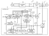
- FIG. 1 is a diagram illustrating a configuration of a motor control apparatus according to an embodiment.
- a motor control apparatus 1 according to the embodiment is connected between an AC source 2 and an AC motor 3 .
- the motor control apparatus 1 extracts power necessary for driving the AC motor 3 from the AC source 2 and supplies it to the AC motor 3 .
- the AC motor 3 is, for example, an interior permanent magnet synchronous motor (IPMSM).
- the motor control apparatus 1 includes a power converting unit 10 , an output current detecting unit 11 , and a control unit 12 .
- the power converting unit 10 includes a converter unit 10 a , an inverter unit 10 b , and a smoothing capacitor C 1 , and supplies the power supplied from the AC source 2 to the AC motor 3 after AC-AC conversion.
- the power converting unit 10 is an example of the drive unit and the output current detecting unit 11 is an example of the current detecting unit.
- the converter unit 10 a includes a rectifier circuit and rectifies the AC voltage supplied from the AC source 2 .
- the voltage rectified by the converter unit 10 a is smoothed by the smoothing capacitor C 1 so as to be converted to a DC voltage.
- the inverter unit 10 b includes two upper and lower switching elements for each phase of the output phase and supplies the DC voltage output from the converter unit 10 a to the AC motor 3 after converting it to an AC voltage by the switching elements.
- the AC motor 3 is driven by the AC voltage output from the inverter unit 10 b .
- the switching element is, for example, an IGBT (Insulated Gate Bipolar Transistor) or a MOSFET.
- the output current detecting unit 11 detects the output current flowing to the AC motor 3 from the inverter unit 10 b . Specifically, the output current detecting unit 11 detects instantaneous values Iu, Iv, and Iw (hereinafter, described as output current values Iu, Iv, and Iw) of the output current flowing to the AC motor 3 from the U phase, V phase, and W phase, which are output phases of the inverter unit 10 b , respectively.
- the output current detecting unit 11 is, for example, a current sensor that detects current by utilizing a Hall element that is a magnetoelectric converting element.
- the control unit 12 outputs a voltage having desired amplitude and frequency from the inverter unit 10 b by controlling each switching element of the inverter unit 10 b , thereby driving the AC motor 3 .
- the control unit 12 includes subtractors 20 and 24 , a speed controller 21 , a injection signal generator 22 , a injection signal coordinate converter 23 , a current controller 25 , a high-frequency current controller 26 , a decoupling controller 27 , an adder 28 , and a PWM calculator 29 . Furthermore, the control unit 12 includes a coordinate converter 30 , a maximum torque controller 31 , an inductance calculator 32 , and a speed and magnetic pole position estimator 33 .
- the injection signal coordinate converter 23 is an example of the current reference generating unit and the current controller 25 , the high-frequency current controller 26 , the decoupling controller 27 , and the adder 28 are an example of the voltage reference generating unit.
- the maximum torque controller 31 is an example of the change amount estimating unit
- the inductance calculator 32 is an example of the inductance estimating unit
- the speed and magnetic pole position estimator 33 is an example of the rotational position estimating unit and the angular frequency estimating unit.
- the subtractor 20 obtains a deviation between a rotor angular frequency reference ⁇ ref and a rotor angular frequency estimated value ⁇ est and outputs it to the speed controller 21 .
- the rotor angular frequency reference ⁇ ref is a reference that defines the angular frequency (hereinafter, described as the rotor angular frequency) of the rotor included in the AC motor 3 and is input from a not-shown upper-level control apparatus. “est” indicates that it is an estimated value.
- the speed controller 21 includes a PI (Proportional Integral) controller and generates a ⁇ -axis current reference I ⁇ _ref by PI control such that the deviation between the rotor angular frequency reference ⁇ ref and the rotor angular frequency estimated value ⁇ est becomes zero.
- the ⁇ -axis current reference I ⁇ _ref is output from the speed controller 21 to the injection signal coordinate converter 23 and the decoupling controller 27 .
- the injection signal generator 22 generates a injection signal S mag , which is a high frequency signal, and outputs it to the injection signal coordinate converter 23 .
- the injection signal S mag is a signal defined by A mag sin(fh ⁇ 2 ⁇ t).
- the injection signal generator 22 outputs a signal sin(fh ⁇ 2 ⁇ t) to the maximum torque controller 31 .
- “fh” indicates the frequency of the injection signal S mag and is set to a value higher than the frequency of the voltage that drives the AC motor 3 .
- a mag is an amplitude of a phase of a current reference vector Is defined by a ⁇ -axis current reference I ⁇ _ref and the ⁇ -axis current reference I ⁇ _ref.
- the frequency fh and the amplitude A mag of the injection signal S mag are set not to interfere in consideration of the control response of the speed controller 21 and the switching frequency of the inverter unit 10 b.
- the direction of the magnetic flux generated by the permanent magnets is defined as the d-axis and the rotational axis for control corresponding to the d-axis is defined as the ⁇ -axis.
- the phase advanced by 90° in an electrical angle from the d-axis is defined as the q-axis and the rotational axis for control corresponding to the q-axis is defined as the ⁇ -axis.
- the injection signal coordinate converter 23 obtains ⁇ -axis current references I ⁇ _href and I ⁇ _href when the phase of the current reference vector Is is varied by the injection signal S mag by the following Equation (1) and outputs them to the subtractor 24 .
- the ⁇ -axis current reference I ⁇ _ref is, for example, set to zero.
- [ I ⁇ _href I ⁇ _href ] [ cos ⁇ ( A mag ⁇ sin ⁇ ( fh ⁇ 2 ⁇ ⁇ ⁇ ⁇ t ) ) - sin ⁇ ( A mag ⁇ sin ⁇ ( fh ⁇ 2 ⁇ ⁇ ⁇ ⁇ t ) ) sin ⁇ ( A mag ⁇ sin ⁇ ( fh ⁇ 2 ⁇ ⁇ ⁇ ⁇ t ) ) cos ⁇ ( A mag ⁇ sin ⁇ ( fh ⁇ 2 ⁇ ⁇ ⁇ t ) ] ⁇ [ I ⁇ _ref I ⁇ _ref ] ( 1 )
- the subtractor 24 subtracts a ⁇ -axis current detected value I ⁇ _fb to be described later from the ⁇ -axis current reference I ⁇ _href on which the injection signal S mag is superposed. Moreover, the subtractor 24 subtracts a ⁇ -axis current detected value I ⁇ _fb to be described later from the ⁇ -axis current reference I ⁇ _href on which the injection signal S mag is superposed. Then, the subtractor 24 outputs each subtraction result to the current controller 25 and the high-frequency current controller 26 .
- the current controller 25 generates a ⁇ -axis voltage reference V ⁇ and a ⁇ -axis voltage reference V ⁇ such that a deviation between the ⁇ -axis current reference I ⁇ _href and the ⁇ -axis current detected value I ⁇ _fb and a deviation between the ⁇ -axis current reference I ⁇ _href and the ⁇ -axis current detected value I ⁇ _fb each become zero.
- the current controller 25 is, for example, composed of a PI controller.
- the current controller 25 outputs the generated ⁇ -axis voltage reference V ⁇ and ⁇ -axis voltage reference V ⁇ to the adder 28 .
- the high-frequency current controller 26 generates ⁇ -axis voltage references V ⁇ _href and V ⁇ _href such that a deviation between the ⁇ -axis current references and the ⁇ -axis current detected values becomes zero.
- the above-described injection signal S mag is a relatively high-frequency wave; therefore, the high-frequency current controller 26 , which is highly responsive compared with a normal current control, is provided to cause the current value to follow the injection signal S mag .
- the high-frequency current controller 26 is, for example, composed of a P (proportional) controller, thereby maintaining the stability.
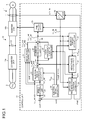
- FIG. 2 is a diagram illustrating a configuration example of the high-frequency current controller 26 .
- the high-frequency current controller 26 includes P controllers 40 and 41 .
- Proportional gains Kp_ ⁇ and Kp_ ⁇ of the P controller 40 are obtained by the following Equation (2).
- ⁇ ACR — hf is the configuration parameter and is, for example, set to a value obtained by multiplying the cutoff frequency in the high-frequency current control by 2 ⁇ .
- Kp — ⁇ L MTPA ⁇ ACR — hf
- Kp — ⁇ L MTPA ⁇ ACR — hf
- the high-frequency current controller 26 updates an inductance value used for calculating the proportional gains Kp_ ⁇ and Kp_ ⁇ online by an inductance compensation value L MTPA from the inductance calculator 32 . Consequently, it is possible to reduce the change in the current response due to the setting error of the inductance.
- the current controller 25 and the decoupling controller 27 the parameters are not updated online to maintain the stability.
- the term online indicates the state where the motor control apparatus 1 is operating.
- the P controller 40 has the above-described proportional gain Kp_ ⁇ and generates the ⁇ -axis voltage reference V ⁇ _href by proportional control such that a deviation between the ⁇ -axis current reference I ⁇ _href and the ⁇ -axis current detected value I ⁇ _fb becomes zero.
- the P controller 41 has the above-described proportional gain Kp_ ⁇ and generates the ⁇ -axis voltage reference V ⁇ _href by proportional control such that a deviation between the ⁇ -axis current reference I ⁇ _href and the ⁇ -axis current detected value I ⁇ _fb becomes zero.
- the decoupling controller 27 generates a ⁇ -axis interference voltage V ⁇ _dcp and a ⁇ -axis interference voltage V ⁇ _dcp that cancel the effect of the ⁇ -axis current component and the ⁇ -axis current component each interfering with the other current component as the ⁇ -axis voltage and the ⁇ -axis voltage.
- Lq may be set equal to L MTPA and Ld may be set equal to Ld*, or Lq may be set equal to L MTPA and Ld may be set equal to L MTPA , on the basis of the inductance compensation value L MTPA output from the speed and magnetic pole position estimator 33 to be described later.
- the adder 28 generates a ⁇ -axis voltage reference V ⁇ _ref and a ⁇ -axis voltage reference V ⁇ _ref by adding the output of the decoupling controller 27 , the output of the current controller 25 , and the output of the high-frequency current controller 26 .
- the ⁇ -axis voltage references V ⁇ _ref and V ⁇ _ref are output to the PWM calculator 29 , the maximum torque controller 31 , and the speed and magnetic pole position estimator 33 from the adder 28 .
- the adder 28 generates the ⁇ -axis voltage reference V ⁇ _ref by adding the ⁇ -axis interference voltage V ⁇ _dcp, the ⁇ -axis voltage reference V ⁇ , and the ⁇ -axis voltage reference V ⁇ _href. Moreover, the adder 28 generates the ⁇ -axis voltage reference V ⁇ _ref by adding the ⁇ -axis interference voltage V ⁇ _dcp, the ⁇ -axis voltage reference V ⁇ , and the ⁇ -axis voltage reference V ⁇ _href.
- the PWM calculator 29 performs rotating coordinate conversion on the ⁇ -axis voltage reference V ⁇ _ref and the ⁇ -axis voltage reference V ⁇ _ref by using rotor position estimated value ⁇ est and furthermore performs two-phase to three-phase conversion to generate voltage references Vu, Vv, and Vw corresponding to the U phase, V phase, and W phase, respectively. Then, the PWM calculator 29 generates a drive signal that drives the switching elements of the inverter unit 10 b by a method, such as a triangular wave comparison, on the basis of the voltage references Vu, Vv, and Vw and supplies the drive signal to the inverter unit 10 b . Consequently, the voltage corresponding to the voltage references Vu, Vv, and Vw is output to the AC motor 3 from the inverter unit 10 b.
- the output current values Iu, Iv, and Iw output from the output current detecting unit 11 are input to the coordinate converter 30 and the coordinate converter 30 performs coordinate conversion to the ⁇ - ⁇ axis coordinate system by using the rotor position estimated value ⁇ est after performing two-phase to three-phase conversion on the output current values Iu, Iv, and Iw.
- the ⁇ - ⁇ axis coordinate system is a rotating coordinate system that rotates in synchronization with the rotor angular frequency estimated value ⁇ est.
- the coordinate converter 30 obtains the ⁇ -axis current detected value I ⁇ _fb, which is a ⁇ -axis component, and the ⁇ -axis current detected value I ⁇ _fb, which is a ⁇ -axis component, by the coordinate conversion to the ⁇ - ⁇ axis coordinate system and outputs them to each of the subtractor 24 , the maximum torque controller 31 , the inductance calculator 32 , and the speed and magnetic pole position estimator 33 .
- the maximum torque controller 31 obtains a phase change amount ⁇ MTPA on the basis of the ⁇ -axis current detected values I ⁇ _fb and I ⁇ _fb, the ⁇ -axis voltage references V ⁇ _ref and V ⁇ _ref, and a signal sin(fh ⁇ 2 ⁇ ), which has a frequency and a phase same as those of the injection signal S mag .
- the phase change amount ⁇ MTPA is a phase change amount of the current reference vector Is after the control is started and is output to the inductance calculator 32 .
- the motor input power Pe includes a copper loss Pc due to the winding resistance of the AC motor 3 and a component of a reactive power Pr in addition to a motor output power P mecha that is a mechanical output of the AC motor 3 .
- the copper loss Pc includes only a DC component.
- the reactive power Pr includes a frequency component whose frequency is the same as that of the injection signal S mag and a frequency component whose frequency is twice that of the injection signal S mag .
- the component whose frequency is the same as that of the injection signal S mag is out of phase by ⁇ /2 with respect to the phase of the injection signal S mag .
- the motor output power P mecha includes a component whose frequency and phase are the same as those of the injection signal S mag .
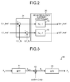
- the maximum torque controller 31 extracts a motor output power fluctuation range Po, which is the amplitude value of a component whose frequency and phase are the same as those of the injection signal S mag , in the motor output power P mecha from the motor input power Pe by a motor output extracting unit 50 illustrated in FIG. 3 .
- FIG. 3 is a diagram illustrating the configuration of the motor output extracting unit 50 included in the maximum torque controller 31 .
- the motor output extracting unit 50 includes a band-pass filter (BPF) 51 , a multiplier 52 , and a low-pass filter (LPF) 53 .
- the BPF 51 is set to pass a signal of the frequency fh and extracts a frequency component P BPF , whose frequency is the same as that of the injection signal S mag , from the input motor input power Pe.
- the output of the BPF 51 is input to the multiplier 52 and is multiplied by a signal sin(fh ⁇ 2 ⁇ t) whose frequency and phase are the same as those of the injection signal S mag . Consequently, the signal, whose frequency and phase are the same as those of the injection signal S mag , in the output of the BPF 51 becomes a DC component and a signal Ph, which includes this DC component, is output from the multiplier 52 .
- the signal Ph output from the multiplier 52 is input to the LPF 53 , and only the DC component is extracted in the LPF 53 and is output from the LPF 53 .
- This DC component is a component that corresponds to the motor output power fluctuation range Po.
- the motor output power fluctuation range Po can be represented by the following Equation (5):
- Po 3 4 ⁇ ⁇ ⁇ ⁇ r ⁇ Amag ⁇ Isa ⁇ ⁇ ( Ld - Lq ) ⁇ Isa ⁇ cos ⁇ ( 2 ⁇ ⁇ ⁇ ⁇ avg ) + ⁇ ⁇ ⁇ f ⁇ cos ⁇ ( ⁇ ⁇ ⁇ avg ) ⁇ ( 5 )
- ⁇ r is the rotor angular velocity
- Isa is the current amplitude of the current reference vector Is
- ⁇ f is the flux linkage constant
- Ld is the d-axis inductance
- Lq is the q-axis inductance
- ⁇ avg is the phase of the current reference vector Is.
- the ⁇ -axis current reference I_ ⁇ ref is equal to zero; therefore, ⁇ avg is the phase of the ⁇ -axis.
- Equation (6) a change ⁇ Te/ ⁇ of a motor generated torque Te with respect to the phase variation of the current reference vector Is is represented by the following Equation (6):
- the motor output power fluctuation range Po is proportional to the change ⁇ Te/ ⁇ of the motor generated torque Te with respect to the phase variation of the current reference vector Is. Therefore, the phase of the current reference vector Is in which the motor output power fluctuation range Po becomes zero becomes the maximum torque axis.
- the motor output power fluctuation range Po is estimated as the change ⁇ Te/ ⁇ of the output torque Te of the AC motor 3 with respect to the current phase change.
- the maximum torque controller 31 includes a phase-change-amount estimating unit that detects the phase change amount ⁇ MTPA of the current reference vector Is at which the motor output power fluctuation range Po becomes a setting value Po* of the motor output power fluctuation range.
- the phase change amount ⁇ MTPA is a phase change amount of the current reference vector Is after the control is started and is a phase change amount that causes the ⁇ -axis to match the maximum torque axis in a steady state.
- the current phase when the control is started is a phase obtained when the inductance value set in the motor control apparatus 1 as an initial value is used for calculation in an extended electromotive force observer 80 to be described later.
- the setting value Po* of the motor output power fluctuation range is normally set to zero or near zero; however, it can also be set to other values.
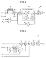
- FIG. 4 is a diagram illustrating the configuration of a phase-change-amount estimating unit 60 included in the maximum torque controller 31 .
- the phase-change-amount estimating unit 60 includes a subtractor 61 , a limiter 62 , switches 63 and 64 , a comparator 65 , a PI controller 66 , an adder 67 , an amplifier 68 , and a limiter 69 .
- the subtractor 61 subtracts the motor output power fluctuation range Po from the setting value Po* of the motor output power fluctuation range and outputs the subtraction result to the limiter 62 and the switch 63 .
- the limiter 62 is a lower limiter. If the subtraction result of the subtractor 61 is less than zero, the limiter 62 outputs zero to the switch 63 , and, if the subtraction result of the subtractor 61 is equal to or more than zero, the limiter 62 directly outputs the subtraction result of the subtractor 61 to the switch 63 .
- the switch 63 is controlled by a reference signal S SW to be described later, which is output from the inductance calculator 32 , and selects and outputs one of the output of the subtractor 61 and the output of the limiter 62 to the switch 64 . Specifically, when the reference signal S SW is at a low level, the switch 63 selects the output of the subtractor 61 and outputs it to the switch 64 , and, when the reference signal S SW is at a high level, the switch 63 selects the output of the limiter 62 and outputs it to the switch 64 .
- the inductance compensation value L MTPA reaches the limit value of a limiter 78 (see FIG. 5 )
- the reference signal S SW is output as a signal at a high level.
- the result obtained by subtracting the motor output power fluctuation range Po from the setting value Po* of the motor output power fluctuation range is negative, zero is input to the PI controller 66 by the limiter 62 and the switch 63 . Therefore, updating of the integrated value in the PI controller 66 is stopped and updating of the phase change amount ⁇ MTPA is stopped.
- the switch 64 selects one of the output of the switch 63 and the output of the amplifier 68 on the basis of the output of the comparator 65 and outputs it to the PI controller 66 .
- the comparator 65 controls the switch 64 by comparing a start power P start with the motor input power Pe. If the motor input power Pe is less than the start power P start , a signal at a low level is output from the comparator 65 . If the motor input power Pe is equal to or more than the start power P start , a signal at a high level is output from the comparator 65 .
- the comparator 65 may compare the start power P start with the motor output power fluctuation range Po instead of the motor input power Pe.
- the switch 64 selects the output of the amplifier 68 , which inverts the integrated output of the PI controller 66 , and outputs the output of the amplifier 68 to the PI controller 66 . Therefore, in a state where the motor input power Pe is less than the start power P start , the signal, which is obtained by inverting the integrated output of the PI controller 66 , is output to the PI controller 66 . Consequently, the output of the phase-change-amount estimating unit 60 is attenuated or maintained at zero by the set time constant of the PI controller 66 .
- the estimation operation of the phase change amount ⁇ MTPA by the phase-change-amount estimating unit 60 is stopped and the phase change amount ⁇ MTPA output from the phase-change-amount estimating unit 60 becomes zero or converges to zero.
- the motor output power fluctuation range Po is calculated from the motor input power Pe; therefore, the motor output power fluctuation range Po is largely affected by the detection accuracy of the output current detecting unit 11 and the output voltage error. Thus, in an area in which the electric energy is small, the accuracy of the motor output power fluctuation range Po degrades.
- the start power P start be determined, for example, to a value (for example, about 10% of the motor rated capacity), at which the calculation accuracy of the motor output power fluctuation range Po starts to degrade with the motor rated capacity as a reference.
- the switch 64 selects the output of the switch 63 . Therefore, in a state where the motor input power Pe is equal to or more than the start power P start , the output of the switch 63 is output to the PI controller 66 .
- the PI controller 66 includes an amplifier 45 of a proportional gain Kp, an amplifier 46 of an integral gain Ki, and an integrator 47 .
- the output of the switch 64 is multiplied by Kp by the amplifier 45 and is output to the adder 67 .
- the output of the switch 64 is multiplied by Ki by the amplifier 46 , is integrated by the integrator 47 , and is output to the adder 67 .
- the adder 67 adds the output of the amplifier 45 and the output of the integrator 47 and outputs the addition result to the limiter 69 .
- the limiter 69 limits the output from the phase-change-amount estimating unit 60 within a predetermined range. In other words, if the output of the adder 67 is within the predetermined range, the limiter 69 outputs the output of the adder 67 directly as the phase change amount ⁇ MTPA , and, if the output of the adder 67 is out of the predetermined range, the limiter 69 outputs the upper limit or the lower limit of the predetermined range as the phase change amount ⁇ MTPA .
- the output of the integrator 47 is inverted by the amplifier 68 and is output to the switch 64 .
- the inductance calculator 32 illustrated in FIG. 1 obtains the inductance compensation value L MTPA from the phase change amount ⁇ MTPA of the current reference vector Is output from the maximum torque controller 31 by the following Equation (7).
- L MTPA ⁇ ⁇ ⁇ f ⁇ sin ⁇ ⁇ ⁇ ⁇ ⁇ ⁇ MTPA Isa ⁇ cos ⁇ ⁇ 2 ⁇ ⁇ ⁇ ⁇ ⁇ MTPA + L d * ( 7 )
- the inductance calculator 32 outputs the inductance compensation value L MTPA obtained as above to the speed and magnetic pole position estimator 33 and the high-frequency current controller 26 .
- the d-axis inductance Ld* and the flux linkage constant ⁇ f are constants set in the motor control apparatus 1 and are, for example, values determined from offline tuning, in which the motor control apparatus 1 is in a non-operating state, or the information on a motor test report.
- FIG. 5 is a diagram illustrating a configuration example of the inductance calculator 32 .
- the inductance calculator 32 includes a sine value calculator 71 , a cosine value calculator 72 , an amplifier 73 , multipliers 74 and 75 , a divider 76 , an adder 77 , the limiter 78 , and a filter 79 .
- the sine value calculator 71 calculates a sine value of the phase change amount ⁇ MTPA .
- a calculation result sin ⁇ MTPA is multiplied by the flux linkage constant ⁇ f by the multiplier 74 .
- the calculation result of the multiplier 74 is output to the divider 76 .
- the cosine value calculator 72 calculates a cosine value of the phase change amount ⁇ MTPA doubled by the amplifier 73 .
- the calculation result cos 2 ⁇ MTPA is multiplied by a current amplitude Isa of the current reference vector Is by the multiplier 75 .
- the calculation result of the multiplier 75 is output to the divider 76 .
- the divider 76 divides the calculation result of the multiplier 74 by the calculation result of the multiplier 75 .
- the calculation result of the divider 76 is output to the adder 77 and the d-axis inductance Ld* is added thereto by the adder 77 .
- the addition result of the adder 77 is output via the limiter 78 and the filter 79 .
- the inductance compensation value L MTPA becomes equal to Ld*.
- the inductance compensation value L MTPA is updated on the basis of the phase change amount ⁇ MTPA output from the maximum torque controller 31 and is output to the high-frequency current controller 26 and the speed and magnetic pole position estimator 33 .
- a lower limit is set in the limiter 78 to prevent overcompensation.
- the limiter 78 outputs the reference signal S SW at a high level to the switch 63 as an antiwindup operation. Consequently, the switch 63 of the phase-change-amount estimating unit 60 illustrated in FIG. 4 is switched and the output of the limiter 62 is output from the switch 63 .
- the limiter 78 compares the input and output signals of the limiter 78 . If the signals are different from each other, the limiter 78 determines that the inductance compensation value L MTPA reaches the lower limit. Moreover, the lower limit is, for example, set to a value that is a half of the d-axis inductance Ld* so that the inductance compensation value L MTPA does not become smaller than the value that is a half of the d-axis inductance Ld*.
- the speed and magnetic pole position estimator 33 detects the rotational speed and the magnetic pole position of the rotor of the AC motor 3 .
- the ⁇ -axis voltage references V ⁇ _ref and V ⁇ _ref, the ⁇ -axis current detected values I ⁇ _fb and I ⁇ _fb, and the inductance compensation value L MTPA are input to the speed and magnetic pole position estimator 33 , and the speed and magnetic pole position estimator 33 obtains the rotor angular frequency estimated value ⁇ est and the rotor position estimated value ⁇ est.
- the speed and magnetic pole position estimator 33 outputs the rotor angular frequency estimated value ⁇ est to the subtractor 20 and outputs the rotor position estimated value ⁇ est to the PWM calculator 29 and the coordinate converter 30 .
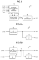
- FIG. 6 is a diagram illustrating a configuration example of the speed and magnetic pole position estimator 33 .
- the speed and magnetic pole position estimator 33 includes the extended electromotive force observer 80 , a phase error calculator 81 , and a PLL controller 82 .
- the extended electromotive force observer 80 obtains a ⁇ -axis extended electromotive force estimated value ⁇ _est and a ⁇ -axis extended electromotive force estimated value ⁇ _est, for example, by the following Equation (8):
- the extended electromotive force observer 80 obtains the ⁇ -axis extended electromotive force estimated values ⁇ _est and ⁇ _est at ([k+1] ⁇ Ts) seconds on the basis of the ⁇ -axis current detected values I ⁇ _fb and I ⁇ _fb, ⁇ -axis current estimated values I ⁇ _est and I ⁇ _est, the ⁇ -axis extended electromotive force estimated values ⁇ _est and ⁇ _est, the speed estimated value, and the motor parameters at (k ⁇ Ts) seconds.
- the extended electromotive force observer 80 obtains the ⁇ -axis extended electromotive force estimated values ⁇ _est and ⁇ _est by using the inductance compensation value L MTPA obtained by the inductance calculator 32 as the q-axis inductance Lq.
- the extended electromotive force observer 80 selectively performs a first estimation process and a second estimation process on the basis of the setting from the outside.
- the ⁇ -axis extended electromotive force estimated values ⁇ _est and ⁇ _est are obtained by setting Lq to be equal to L MTPA and setting Ld to be equal to Ld* in the above Equation (9).
- the ⁇ -axis extended electromotive force estimated values ⁇ _est and ⁇ _est are obtained by setting Lq to be equal to L MTPA and setting Ld to be equal to L MTPA in the above Equation (9).
- the ⁇ -axis extended electromotive force estimated values ⁇ _est and ⁇ _est are input to the phase error calculator 81 from the extended electromotive force observer 80 and the phase error calculator 81 obtains a phase error estimated value ⁇ est by the following Equation (10) and outputs it to the PLL controller 82 .
- ⁇ ⁇ ⁇ ⁇ est tan - 1 ⁇ ( - ⁇ ⁇ ⁇ ⁇ _ ⁇ ⁇ est ⁇ ⁇ ⁇ ⁇ _ ⁇ ⁇ est ) ( 10 )
- the ⁇ -axis extended electromotive force estimated values ⁇ _est and ⁇ _est include a voltage error component generated due to the change of speed, the change in the load state, and the parameter error.
- the phase error estimated value ⁇ est is obtained as represented by the above Equation (10). Therefore, it is found that the inductance compensation value L MTPA obtained by the inductance calculator 32 is reflected in the phase error estimated value ⁇ est.
- the PLL controller 82 obtains the rotor position estimated value ⁇ est and the rotor angular frequency estimated value ⁇ est on the basis of the phase error estimated value ⁇ est output from the phase error calculator 81 .
- FIG. 7A and FIG. 7B illustrate a configuration example of the PLL controller 82 .
- the PLL controller 82 obtains the rotor position estimated value ⁇ est and the rotor angular frequency estimated value ⁇ est by controlling such that the phase error estimated value ⁇ est estimated from the ⁇ -axis extended electromotive force estimated values ⁇ _est and ⁇ _est becomes zero.
- the PLL controller 82 illustrated in FIG. 7A includes a PI controller 91 and an integrator 92 , and obtains the rotor angular frequency estimated value ⁇ est by performing the PI control on the phase error estimated value ⁇ est by the PI controller 91 and obtains the rotor position estimated value ⁇ est by integrating the rotor angular frequency estimated value ⁇ est by the integrator 92 .
- the ⁇ - ⁇ axis coordinates which are a control coordinate system, can be caused to match the d-q axis coordinates, which are a rotor coordinate system, by controlling the phase error estimated value ⁇ est to zero.
- parameters do not match true values; therefore, even if the phase error estimated value ⁇ est is zero in the control, the ⁇ - ⁇ axis coordinates do not match the d-q axis coordinates.
- the parameters are determined such that the ⁇ -axis matches the maximum torque axis, and, as a result, as in the PLL controller 82 illustrated in FIG.
- the ⁇ -axis in the ⁇ - ⁇ axis coordinates which are a control coordinate system, is controlled to match the maximum torque axis by controlling the phase error estimated value ⁇ est to zero. Because the current reference vector Is is always on the ⁇ -axis, the maximum torque control can be performed by causing the ⁇ -axis to match the maximum torque axis.
- the PLL controller 82 may have a configuration illustrated in FIG. 7B .
- the PLL controller 82 illustrated in FIG. 7B includes a PI controller 93 , a divider 94 , an adder 95 , and an integrator 96 .
- the speed is approximately estimated by dividing the ⁇ -axis extended electromotive force estimated value ⁇ _est by an induced voltage constant ⁇ by the divider 94
- the rotor angular frequency estimated value ⁇ est is obtained by adding the estimated speed to the output of the PI controller 93 by the adder 95 .
- the rotor position estimated value ⁇ est is obtained by integrating the rotor angular frequency estimated value ⁇ est by the integrator 96 .
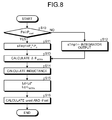
- FIG. 8 and FIG. 9 are diagrams illustrating the flow of the calculation process of the rotor angular frequency estimated value ⁇ est and the rotor position estimated value ⁇ est in the control unit 12 .
- FIG. 8 illustrates the flow of the first calculation process in the case where the above-described first estimation process is selected
- FIG. 9 illustrates the flow of the second calculation process in the case where the above-described second estimation process is selected.
- the maximum torque controller 31 of the control unit 12 compares the start power P start with the motor input power Pe (Step S 10 ). If the motor input power Pe is equal to or more than the start power P start (Yes in Step S 10 ), the maximum torque controller 31 sets the target for the PI control to Po-Po* (Step S 11 ). On the other hand, if the motor input power Pe is less than the start power P start (No in Step S 10 ), the maximum torque controller 31 sets the target for the PI control to an inverse of the integral output (Step S 12 ).
- the maximum torque controller 31 obtains the phase change amount ⁇ MTPA by performing the PI control on the basis of the setting in Steps S 11 and S 12 (Step S 13 ). Then, the inductance calculator 32 obtains the inductance compensation value L MTPA on the basis of the phase change amount ⁇ MTPA output from the maximum torque controller 31 (Step S 14 ).
- the speed and magnetic pole position estimator 33 sets the q-axis inductance Lq and the d-axis inductance Ld that are motor parameters. Specifically, the speed and magnetic pole position estimator 33 sets the inductance compensation value L MTPA as the q-axis inductance Lq and sets the d-axis inductance Ld*, which is preset, as the d-axis inductance Ld (Step S 15 ). Then, the speed and magnetic pole position estimator 33 obtains the rotor position estimated value ⁇ est and the rotor angular frequency estimated value ⁇ est on the basis of the motor parameters set in Step S 15 (Step S 16 ).
- Step S 11 to S 14 and S 16 are the same as those in the first calculation process illustrated in FIG. 8 and the process in Step S 25 is different from that in the first calculation process.
- Step S 25 the speed and magnetic pole position estimator 33 sets the inductance compensation value L MTPA as the q-axis inductance Lq and sets the inductance compensation value L MTPA as the d-axis inductance Ld. Then, the speed and magnetic pole position estimator 33 obtains the rotor position estimated value ⁇ est and the rotor angular frequency estimated value ⁇ est in accordance with the motor parameters set as above.
- the motor control apparatus 1 includes the maximum torque controller 31 , the inductance calculator 32 , and the speed and magnetic pole position estimator 33 .
- the maximum torque controller 31 estimates the motor output power fluctuation range Po of the AC motor 3 corresponding to the injection signal S mag that is a high frequency signal whose frequency is higher than that of the drive frequency of the AC motor 3 .
- the inductance calculator 32 estimates the inductance compensation value L MTPA that obtains the maximum torque on the basis of the motor output power fluctuation range Po and sets it in the speed and magnetic pole position estimator 33 as the q-axis inductance.
- the speed and magnetic pole position estimator 33 estimates the rotor position estimated value ⁇ est, which is the rotational position of the rotor of the AC motor 3 , from the motor parameters that include the q-axis inductance Lq set by the inductance calculator 32 on the basis of the ⁇ -axis current detected values I ⁇ _fb and I ⁇ _fb, which are detected values of the output current to the AC motor 3 , and the ⁇ -axis voltage references V ⁇ _ref and V ⁇ _ref.
- the motor control apparatus 1 can set the q-axis inductance in which an error is intentionally induced from its true value by obtaining the inductance compensation value L MTPA to be set as the q-axis inductance online without using a fixed value and motor parameters (Ld, Lq, and ⁇ a). Therefore, for example, even if there is an error in the motor parameters or variation in the motor parameters, the speed and magnetic pole position estimator 33 can be stably operated and thus the maximum torque control can be accurately performed.
Landscapes
- Engineering & Computer Science (AREA)
- Power Engineering (AREA)
- Control Of Ac Motors In General (AREA)
- Control Of Motors That Do Not Use Commutators (AREA)
Applications Claiming Priority (2)
| Application Number | Priority Date | Filing Date | Title |
|---|---|---|---|
| JP2012181129A JP5644820B2 (ja) | 2012-08-17 | 2012-08-17 | モータ制御装置 |
| JP2012-181129 | 2012-08-17 |
Publications (2)
| Publication Number | Publication Date |
|---|---|
| US20140049202A1 US20140049202A1 (en) | 2014-02-20 |
| US8988027B2 true US8988027B2 (en) | 2015-03-24 |
Family
ID=47900783
Family Applications (1)
| Application Number | Title | Priority Date | Filing Date |
|---|---|---|---|
| US13/792,201 Active 2033-10-11 US8988027B2 (en) | 2012-08-17 | 2013-03-11 | Motor control apparatus and motor control method |
Country Status (7)
| Country | Link |
|---|---|
| US (1) | US8988027B2 (ko) |
| EP (1) | EP2698916A2 (ko) |
| JP (1) | JP5644820B2 (ko) |
| KR (1) | KR101493144B1 (ko) |
| CN (1) | CN103595326B (ko) |
| BR (1) | BR102013005561A2 (ko) |
| TW (1) | TWI499198B (ko) |
Cited By (2)
| Publication number | Priority date | Publication date | Assignee | Title |
|---|---|---|---|---|
| US20160099667A1 (en) * | 2014-10-01 | 2016-04-07 | Hyundai Motor Company | Sensorless control method and system for motor |
| US20160141994A1 (en) * | 2013-08-19 | 2016-05-19 | Kabushiki Kaisha Yaskawa Denki | Motor drive system and motor control device |
Families Citing this family (34)
| Publication number | Priority date | Publication date | Assignee | Title |
|---|---|---|---|---|
| DE112012007011T5 (de) * | 2012-10-12 | 2015-07-02 | Mitsubishi Electric Corporation | Synchronmotor-Steuervorrichtung |
| JP2015136237A (ja) * | 2014-01-17 | 2015-07-27 | 株式会社安川電機 | 回転電機制御装置、回転電機制御方法、及び制御マップの作成方法 |
| JP2016046859A (ja) * | 2014-08-20 | 2016-04-04 | 株式会社リコー | モータ駆動制御装置及びモータ駆動制御方法 |
| JPWO2016121237A1 (ja) * | 2015-01-28 | 2017-08-24 | 株式会社東芝 | インバータ制御装置及びモータ駆動システム |
| JP6380251B2 (ja) * | 2015-06-19 | 2018-08-29 | 株式会社デンソー | 回転電機の制御装置 |
| JP6241460B2 (ja) * | 2015-08-25 | 2017-12-06 | 株式会社デンソー | 電動機の制御装置 |
| JP6490540B2 (ja) * | 2015-08-25 | 2019-03-27 | 株式会社東芝 | 回転位置検出装置,空気調和機及び回転位置検出方法 |
| DE102015114750A1 (de) * | 2015-09-03 | 2017-03-09 | Technische Universität Braunschweig | Verfahren zur Steuerung einer elektrischen Maschine, Computerprogramm, Reglereinrichtung sowie elektrische Maschine |
| TWI552506B (zh) * | 2015-10-22 | 2016-10-01 | 東元電機股份有限公司 | 馬達驅動器之控制系統 |
| CN106695688B (zh) * | 2015-11-13 | 2019-03-15 | 丰民金属工业股份有限公司 | 电动冲击式工具的扭力控制装置及其方法 |
| JP6390649B2 (ja) * | 2016-03-18 | 2018-09-19 | 株式会社安川電機 | 電力変換装置、電動機の動力推定方法及び電動機の制御方法 |
| TWI612766B (zh) * | 2016-07-22 | 2018-01-21 | 祥誠科技股份有限公司 | 馬達控制系統 |
| CH712828A1 (de) * | 2016-08-22 | 2018-02-28 | Lakeview Innvovation Ltd | Verfahren zur sensorlosen Bestimmung der Orientierung des Rotors eines eisenlosen PMSM-Motors. |
| JP6899897B2 (ja) * | 2017-05-31 | 2021-07-07 | 株式会社日立製作所 | 状態監視装置、並びに機器システム |
| KR101939476B1 (ko) * | 2017-07-11 | 2019-01-16 | 엘지전자 주식회사 | 모터 구동 장치 |
| KR102599388B1 (ko) * | 2017-09-01 | 2023-11-09 | 현대자동차주식회사 | 피드백 제어방법 및 시스템 |
| US10574161B2 (en) | 2017-09-22 | 2020-02-25 | Nidec Motor Corporation | System and computer-implemented method for reducing angle error in electric motors |
| KR102228441B1 (ko) * | 2018-06-21 | 2021-03-15 | 단국대학교 산학협력단 | 영구자석 동기 전동기의 센서리스 제어 시스템 및 방법 |
| CN108923721B (zh) * | 2018-08-20 | 2020-09-25 | 广东美的暖通设备有限公司 | 电机变频驱动系统与多联机中央空调器 |
| CN109474219B (zh) * | 2018-11-06 | 2021-12-03 | 天津大学 | 一种基于分频耦合的电机参数辨识方法 |
| JP2020088978A (ja) * | 2018-11-20 | 2020-06-04 | 株式会社日立産機システム | 電力変換装置 |
| KR102216667B1 (ko) * | 2018-12-26 | 2021-02-17 | 주식회사 현대케피코 | 모터 전원 이상 제어 장치 및 방법 |
| JP7289662B2 (ja) * | 2019-01-31 | 2023-06-12 | キヤノン株式会社 | 画像形成装置 |
| JP7251424B2 (ja) * | 2019-09-20 | 2023-04-04 | 株式会社明電舎 | インバータ装置及びインバータ装置の制御方法 |
| TWI716175B (zh) * | 2019-10-31 | 2021-01-11 | 東元電機股份有限公司 | 電流響應補償系統及其方法 |
| JP7294993B2 (ja) * | 2019-11-21 | 2023-06-20 | ファナック株式会社 | 磁極方向検出装置および磁極方向検出方法 |
| JP7363524B2 (ja) * | 2020-01-27 | 2023-10-18 | 株式会社富士通ゼネラル | センサレスモータ制御装置 |
| CN111277194A (zh) * | 2020-03-13 | 2020-06-12 | 北京京环装备设计研究院有限公司 | 电感参数获取方法及装置 |
| CN112019118B (zh) * | 2020-08-25 | 2022-04-15 | 科诺伟业风能设备(北京)有限公司 | 一种直驱风电变流器无定子电压测量矢量控制方法 |
| JP2022175990A (ja) * | 2021-05-14 | 2022-11-25 | 株式会社日立産機システム | 電力変換装置 |
| CN113346813B (zh) * | 2021-06-11 | 2022-05-27 | 中国科学院深圳先进技术研究院 | 最大转矩电流比控制方法、装置、终端设备及存储介质 |
| CN113783494B (zh) * | 2021-08-30 | 2023-09-26 | 江苏大学 | 无位置传感器内置式永磁同步电机的最大转矩电流比控制 |
| CN114050752B (zh) * | 2021-10-12 | 2024-02-09 | 广州极飞科技股份有限公司 | 电机的磁场定向控制、电机参数确定的方法和装置 |
| KR102500019B1 (ko) * | 2022-12-29 | 2023-02-16 | 주식회사 에스엠전자 | 2승저감부하에 연결된 모터의 운영전력효율이 개선된 제어관제시스템 |
Citations (7)
| Publication number | Priority date | Publication date | Assignee | Title |
|---|---|---|---|---|
| US20040232862A1 (en) * | 2001-08-06 | 2004-11-25 | Wogari Mengesha Mamo | Electric motor pole position sensing method, pole position sensing apparatus, and electric motor control apparatus using the same |
| US7157876B2 (en) * | 2002-10-03 | 2007-01-02 | Kabushiki Kaisha Yaskawa Denki | Motor magnetic pole position estimation device and control device |
| JP2008092657A (ja) | 2006-10-02 | 2008-04-17 | Hitachi Ltd | 永久磁石モータのインダクタンス同定制御装置及びインバータモジュール |
| US20090039810A1 (en) * | 2007-08-06 | 2009-02-12 | Baumuller Nurnberg Gmbh | System for seamless estimation of speed and/or position, including standstill of a permanent magnet rotor of an electric motor |
| JP2009291072A (ja) | 2005-08-26 | 2009-12-10 | Sanyo Electric Co Ltd | モータ制御装置 |
| JP2011041343A (ja) | 2009-08-06 | 2011-02-24 | Toshiba Corp | モータ駆動装置及びモータ駆動方法 |
| US8330402B2 (en) * | 2009-01-21 | 2012-12-11 | Kabushiki Kaisha Yaskawa Denki | Alternating-current motor control apparatus |
Family Cites Families (5)
| Publication number | Priority date | Publication date | Assignee | Title |
|---|---|---|---|---|
| US6737828B2 (en) * | 2001-07-19 | 2004-05-18 | Matsushita Electric Industrial Co., Ltd. | Washing machine motor drive device |
| JP2005151640A (ja) | 2003-11-12 | 2005-06-09 | Toyo Electric Mfg Co Ltd | 高周波電圧重畳電動機制御装置 |
| JP4771126B2 (ja) | 2005-09-28 | 2011-09-14 | 富士電機株式会社 | 同期電動機駆動装置 |
| ES2658576T3 (es) * | 2007-09-27 | 2018-03-12 | Mitsubishi Electric Corporation | Controlador de máquina eléctrica rotativa |
| CN101977012A (zh) * | 2010-11-09 | 2011-02-16 | 上海川邻精密配件有限公司 | 无传感器磁场定向控制车轮方法及装置 |
-
2012
- 2012-08-17 JP JP2012181129A patent/JP5644820B2/ja not_active Expired - Fee Related
-
2013
- 2013-03-07 BR BRBR102013005561-1A patent/BR102013005561A2/pt not_active IP Right Cessation
- 2013-03-07 TW TW102108057A patent/TWI499198B/zh not_active IP Right Cessation
- 2013-03-11 US US13/792,201 patent/US8988027B2/en active Active
- 2013-03-13 KR KR20130026542A patent/KR101493144B1/ko not_active IP Right Cessation
- 2013-03-14 EP EP13159098.6A patent/EP2698916A2/en not_active Withdrawn
- 2013-03-15 CN CN201310082975.9A patent/CN103595326B/zh active Active
Patent Citations (7)
| Publication number | Priority date | Publication date | Assignee | Title |
|---|---|---|---|---|
| US20040232862A1 (en) * | 2001-08-06 | 2004-11-25 | Wogari Mengesha Mamo | Electric motor pole position sensing method, pole position sensing apparatus, and electric motor control apparatus using the same |
| US7157876B2 (en) * | 2002-10-03 | 2007-01-02 | Kabushiki Kaisha Yaskawa Denki | Motor magnetic pole position estimation device and control device |
| JP2009291072A (ja) | 2005-08-26 | 2009-12-10 | Sanyo Electric Co Ltd | モータ制御装置 |
| JP2008092657A (ja) | 2006-10-02 | 2008-04-17 | Hitachi Ltd | 永久磁石モータのインダクタンス同定制御装置及びインバータモジュール |
| US20090039810A1 (en) * | 2007-08-06 | 2009-02-12 | Baumuller Nurnberg Gmbh | System for seamless estimation of speed and/or position, including standstill of a permanent magnet rotor of an electric motor |
| US8330402B2 (en) * | 2009-01-21 | 2012-12-11 | Kabushiki Kaisha Yaskawa Denki | Alternating-current motor control apparatus |
| JP2011041343A (ja) | 2009-08-06 | 2011-02-24 | Toshiba Corp | モータ駆動装置及びモータ駆動方法 |
Non-Patent Citations (2)
| Title |
|---|
| Japanese Office Action for corresponding JP Application No. 2012-181129, Apr. 1, 2014. |
| Taiwanese Office Action for corresponding TW Application No. 102108057, Nov. 3, 2014. |
Cited By (3)
| Publication number | Priority date | Publication date | Assignee | Title |
|---|---|---|---|---|
| US20160141994A1 (en) * | 2013-08-19 | 2016-05-19 | Kabushiki Kaisha Yaskawa Denki | Motor drive system and motor control device |
| US20160099667A1 (en) * | 2014-10-01 | 2016-04-07 | Hyundai Motor Company | Sensorless control method and system for motor |
| US9407182B2 (en) * | 2014-10-01 | 2016-08-02 | Hyundai Motor Company | Sensorless control method and system for motor |
Also Published As
| Publication number | Publication date |
|---|---|
| EP2698916A2 (en) | 2014-02-19 |
| US20140049202A1 (en) | 2014-02-20 |
| TW201409926A (zh) | 2014-03-01 |
| KR20140023203A (ko) | 2014-02-26 |
| TWI499198B (zh) | 2015-09-01 |
| JP2014039414A (ja) | 2014-02-27 |
| CN103595326A (zh) | 2014-02-19 |
| BR102013005561A2 (pt) | 2015-07-07 |
| CN103595326B (zh) | 2016-04-20 |
| JP5644820B2 (ja) | 2014-12-24 |
| KR101493144B1 (ko) | 2015-02-12 |
Similar Documents
| Publication | Publication Date | Title |
|---|---|---|
| US8988027B2 (en) | Motor control apparatus and motor control method | |
| JP4988329B2 (ja) | 永久磁石モータのビートレス制御装置 | |
| JP5761243B2 (ja) | モータ制御装置および磁極位置推定方法 | |
| KR100423715B1 (ko) | 동기전동기 제어장치, 동기전동기의 제어방법 | |
| US9825579B2 (en) | Temperature estimating apparatus for synchronous motor | |
| JP4578700B2 (ja) | ブラシレスdcモータの制御装置 | |
| KR101046802B1 (ko) | 교류 회전기의 제어 장치 및 이 제어 장치를 사용한 교류회전기의 전기적 정수 측정 방법 | |
| JP5025142B2 (ja) | モータ制御装置 | |
| KR101376389B1 (ko) | 유도전동기용 자속 제어장치 | |
| US20170264227A1 (en) | Inverter control device and motor drive system | |
| JP3832443B2 (ja) | 交流電動機の制御装置 | |
| US11515821B2 (en) | Control device for rotating electrical machine | |
| US20220255481A1 (en) | Electric power conversion with phase correction | |
| JP2009273254A (ja) | 永久磁石形同期電動機の制御装置 | |
| JP7304891B2 (ja) | 回転機の制御装置および電動車両の制御装置 | |
| JP6541092B2 (ja) | 永久磁石同期電動機の制御装置 | |
| KR102409792B1 (ko) | 영구 자석 동기 전동기의 제어 장치, 마이크로 컴퓨터, 전동기 시스템 및 영구 자석 동기 전동기의 운전 방법 | |
| JP7251424B2 (ja) | インバータ装置及びインバータ装置の制御方法 | |
| JP7226211B2 (ja) | インバータ装置及びインバータ装置の制御方法 | |
| JP6422796B2 (ja) | 同期機制御装置及び駆動システム | |
| JP2011152046A (ja) | モータ制御装置 | |
| US20230198438A1 (en) | Rotary machine control device | |
| JP2010057210A (ja) | 交流電動機の制御装置 | |
| JP2020178508A (ja) | インバータ装置及びインバータ装置の制御方法 | |
| JP2004242483A (ja) | 誘導電動機の制御方法 |
Legal Events
| Date | Code | Title | Description |
|---|---|---|---|
| AS | Assignment |
Owner name: KABUSHIKI KAISHA YASKAWA DENKI, JAPAN Free format text: ASSIGNMENT OF ASSIGNORS INTEREST;ASSIGNORS:FUKUMARU, SHINGO;MORIMOTO, SHINYA;IURA, HIDEAKI;AND OTHERS;SIGNING DATES FROM 20130225 TO 20130304;REEL/FRAME:029957/0965 |
|
| STCF | Information on status: patent grant |
Free format text: PATENTED CASE |
|
| MAFP | Maintenance fee payment |
Free format text: PAYMENT OF MAINTENANCE FEE, 4TH YEAR, LARGE ENTITY (ORIGINAL EVENT CODE: M1551); ENTITY STATUS OF PATENT OWNER: LARGE ENTITY Year of fee payment: 4 |
|
| MAFP | Maintenance fee payment |
Free format text: PAYMENT OF MAINTENANCE FEE, 8TH YEAR, LARGE ENTITY (ORIGINAL EVENT CODE: M1552); ENTITY STATUS OF PATENT OWNER: LARGE ENTITY Year of fee payment: 8 |