US8884570B2 - Position control system - Google Patents
Position control system Download PDFInfo
- Publication number
- US8884570B2 US8884570B2 US13/943,102 US201313943102A US8884570B2 US 8884570 B2 US8884570 B2 US 8884570B2 US 201313943102 A US201313943102 A US 201313943102A US 8884570 B2 US8884570 B2 US 8884570B2
- Authority
- US
- United States
- Prior art keywords
- control
- moving
- driving force
- drive
- deviation
- Prior art date
- Legal status (The legal status is an assumption and is not a legal conclusion. Google has not performed a legal analysis and makes no representation as to the accuracy of the status listed.)
- Active
Links
Images


Classifications
-
- G—PHYSICS
- G03—PHOTOGRAPHY; CINEMATOGRAPHY; ANALOGOUS TECHNIQUES USING WAVES OTHER THAN OPTICAL WAVES; ELECTROGRAPHY; HOLOGRAPHY
- G03B—APPARATUS OR ARRANGEMENTS FOR TAKING PHOTOGRAPHS OR FOR PROJECTING OR VIEWING THEM; APPARATUS OR ARRANGEMENTS EMPLOYING ANALOGOUS TECHNIQUES USING WAVES OTHER THAN OPTICAL WAVES; ACCESSORIES THEREFOR
- G03B5/00—Adjustment of optical system relative to image or object surface other than for focusing
- G03B5/02—Lateral adjustment of lens
-
- G—PHYSICS
- G03—PHOTOGRAPHY; CINEMATOGRAPHY; ANALOGOUS TECHNIQUES USING WAVES OTHER THAN OPTICAL WAVES; ELECTROGRAPHY; HOLOGRAPHY
- G03B—APPARATUS OR ARRANGEMENTS FOR TAKING PHOTOGRAPHS OR FOR PROJECTING OR VIEWING THEM; APPARATUS OR ARRANGEMENTS EMPLOYING ANALOGOUS TECHNIQUES USING WAVES OTHER THAN OPTICAL WAVES; ACCESSORIES THEREFOR
- G03B5/00—Adjustment of optical system relative to image or object surface other than for focusing
- G03B5/08—Swing backs
-
- G—PHYSICS
- G03—PHOTOGRAPHY; CINEMATOGRAPHY; ANALOGOUS TECHNIQUES USING WAVES OTHER THAN OPTICAL WAVES; ELECTROGRAPHY; HOLOGRAPHY
- G03B—APPARATUS OR ARRANGEMENTS FOR TAKING PHOTOGRAPHS OR FOR PROJECTING OR VIEWING THEM; APPARATUS OR ARRANGEMENTS EMPLOYING ANALOGOUS TECHNIQUES USING WAVES OTHER THAN OPTICAL WAVES; ACCESSORIES THEREFOR
- G03B5/00—Adjustment of optical system relative to image or object surface other than for focusing
-
- G—PHYSICS
- G05—CONTROLLING; REGULATING
- G05B—CONTROL OR REGULATING SYSTEMS IN GENERAL; FUNCTIONAL ELEMENTS OF SUCH SYSTEMS; MONITORING OR TESTING ARRANGEMENTS FOR SUCH SYSTEMS OR ELEMENTS
- G05B11/00—Automatic controllers
- G05B11/01—Automatic controllers electric
- G05B11/06—Automatic controllers electric in which the output signal represents a continuous function of the deviation from the desired value, i.e. continuous controllers
-
- H—ELECTRICITY
- H02—GENERATION; CONVERSION OR DISTRIBUTION OF ELECTRIC POWER
- H02P—CONTROL OR REGULATION OF ELECTRIC MOTORS, ELECTRIC GENERATORS OR DYNAMO-ELECTRIC CONVERTERS; CONTROLLING TRANSFORMERS, REACTORS OR CHOKE COILS
- H02P25/00—Arrangements or methods for the control of AC motors characterised by the kind of AC motor or by structural details
- H02P25/02—Arrangements or methods for the control of AC motors characterised by the kind of AC motor or by structural details characterised by the kind of motor
- H02P25/022—Synchronous motors
- H02P25/028—Synchronous motors with four quadrant control
-
- H—ELECTRICITY
- H02—GENERATION; CONVERSION OR DISTRIBUTION OF ELECTRIC POWER
- H02P—CONTROL OR REGULATION OF ELECTRIC MOTORS, ELECTRIC GENERATORS OR DYNAMO-ELECTRIC CONVERTERS; CONTROLLING TRANSFORMERS, REACTORS OR CHOKE COILS
- H02P25/00—Arrangements or methods for the control of AC motors characterised by the kind of AC motor or by structural details
- H02P25/02—Arrangements or methods for the control of AC motors characterised by the kind of AC motor or by structural details characterised by the kind of motor
- H02P25/032—Reciprocating, oscillating or vibrating motors
- H02P25/034—Voice coil motors
-
- H—ELECTRICITY
- H02—GENERATION; CONVERSION OR DISTRIBUTION OF ELECTRIC POWER
- H02P—CONTROL OR REGULATION OF ELECTRIC MOTORS, ELECTRIC GENERATORS OR DYNAMO-ELECTRIC CONVERTERS; CONTROLLING TRANSFORMERS, REACTORS OR CHOKE COILS
- H02P25/00—Arrangements or methods for the control of AC motors characterised by the kind of AC motor or by structural details
- H02P25/02—Arrangements or methods for the control of AC motors characterised by the kind of AC motor or by structural details characterised by the kind of motor
- H02P25/06—Linear motors
-
- H—ELECTRICITY
- H04—ELECTRIC COMMUNICATION TECHNIQUE
- H04N—PICTORIAL COMMUNICATION, e.g. TELEVISION
- H04N23/00—Cameras or camera modules comprising electronic image sensors; Control thereof
- H04N23/50—Constructional details
- H04N23/54—Mounting of pick-up tubes, electronic image sensors, deviation or focusing coils
-
- H—ELECTRICITY
- H04—ELECTRIC COMMUNICATION TECHNIQUE
- H04N—PICTORIAL COMMUNICATION, e.g. TELEVISION
- H04N23/00—Cameras or camera modules comprising electronic image sensors; Control thereof
- H04N23/60—Control of cameras or camera modules
- H04N23/68—Control of cameras or camera modules for stable pick-up of the scene, e.g. compensating for camera body vibrations
- H04N23/681—Motion detection
- H04N23/6812—Motion detection based on additional sensors, e.g. acceleration sensors
-
- H—ELECTRICITY
- H04—ELECTRIC COMMUNICATION TECHNIQUE
- H04N—PICTORIAL COMMUNICATION, e.g. TELEVISION
- H04N23/00—Cameras or camera modules comprising electronic image sensors; Control thereof
- H04N23/60—Control of cameras or camera modules
- H04N23/68—Control of cameras or camera modules for stable pick-up of the scene, e.g. compensating for camera body vibrations
- H04N23/682—Vibration or motion blur correction
- H04N23/685—Vibration or motion blur correction performed by mechanical compensation
-
- H04N5/2253—
-
- H04N5/23258—
-
- H04N5/2328—
-
- G—PHYSICS
- G03—PHOTOGRAPHY; CINEMATOGRAPHY; ANALOGOUS TECHNIQUES USING WAVES OTHER THAN OPTICAL WAVES; ELECTROGRAPHY; HOLOGRAPHY
- G03B—APPARATUS OR ARRANGEMENTS FOR TAKING PHOTOGRAPHS OR FOR PROJECTING OR VIEWING THEM; APPARATUS OR ARRANGEMENTS EMPLOYING ANALOGOUS TECHNIQUES USING WAVES OTHER THAN OPTICAL WAVES; ACCESSORIES THEREFOR
- G03B2205/00—Adjustment of optical system relative to image or object surface other than for focusing
- G03B2205/0007—Movement of one or more optical elements for control of motion blur
- G03B2205/0015—Movement of one or more optical elements for control of motion blur by displacing one or more optical elements normal to the optical axis
-
- G—PHYSICS
- G03—PHOTOGRAPHY; CINEMATOGRAPHY; ANALOGOUS TECHNIQUES USING WAVES OTHER THAN OPTICAL WAVES; ELECTROGRAPHY; HOLOGRAPHY
- G03B—APPARATUS OR ARRANGEMENTS FOR TAKING PHOTOGRAPHS OR FOR PROJECTING OR VIEWING THEM; APPARATUS OR ARRANGEMENTS EMPLOYING ANALOGOUS TECHNIQUES USING WAVES OTHER THAN OPTICAL WAVES; ACCESSORIES THEREFOR
- G03B2205/00—Adjustment of optical system relative to image or object surface other than for focusing
- G03B2205/0007—Movement of one or more optical elements for control of motion blur
- G03B2205/0038—Movement of one or more optical elements for control of motion blur by displacing the image plane with respect to the optical axis
-
- G—PHYSICS
- G03—PHOTOGRAPHY; CINEMATOGRAPHY; ANALOGOUS TECHNIQUES USING WAVES OTHER THAN OPTICAL WAVES; ELECTROGRAPHY; HOLOGRAPHY
- G03B—APPARATUS OR ARRANGEMENTS FOR TAKING PHOTOGRAPHS OR FOR PROJECTING OR VIEWING THEM; APPARATUS OR ARRANGEMENTS EMPLOYING ANALOGOUS TECHNIQUES USING WAVES OTHER THAN OPTICAL WAVES; ACCESSORIES THEREFOR
- G03B2205/00—Adjustment of optical system relative to image or object surface other than for focusing
- G03B2205/0053—Driving means for the movement of one or more optical element
- G03B2205/0069—Driving means for the movement of one or more optical element using electromagnetic actuators, e.g. voice coils
Definitions
- the present invention relates generally to a position control system for applying driving force to a moving part for its movement.
- a digital camera includes an image shake corrector in which an imaging device or an optical element such as a lens is moved for the purpose of preventing image shakes at the time of imaging.
- a voice coil motor VCM
- VCM voice coil motor
- the voice coil motor is operated by energizing the coil to generate driving force proportional to a magnetic flux through the coil.
- the use of the voice coil motor enables fast and high-precision drive as well as size reductions.
- Patent Publication 1 JP(A) 2011-75834 discloses the use of a position detector with an image shake corrector using such a voice coil motor. In this position detector, there is a Hall element used that is capable of detecting changes in the magnetic flux generated from the magnet. Patent Publication 1 teaches that a moving frame is stably supported by taking into consideration the polarity location of the magnet used with the voice coil motor and a magnet used with the position detector.
- One aspect of the invention to this end provides a position control system comprising:
- a position-detection portion that detects a position of said moving portion with respect to a reference position of said fixed portion
- control portion that controls the driving force of said drive portion
- control portion is operable to determine the driving force to be applied to said drive portion based on a correction coefficient acquired based on a first deviation that is a difference between the drive target position inputted into said input portion and said reference position, and a second deviation that is a difference between a position detected by said position-detection portion and the drive target position inputted into said input component.
- Another aspect of the invention provides a position control system comprising:
- a position-detection portion that detects a position of said moving portion with respect to a reference position of said fixed portion
- control portion that controls the driving force of said drive portion
- control portion is operable to determine the driving force to be applied to said drive portion based on a correction coefficient acquired based on a first deviation that is a difference between a position detected by said position-detection portion and said reference position, and a second deviation that is a difference between the position detected by said position-detection portion and the drive target position inputted into said input portion.
- FIG. 1 is illustrative of the image shake corrector 1 before assembly according to one embodiment of the invention.
- FIG. 2 is illustrative of the fixed portion 10 .
- FIG. 3 is illustrative of the moving portion 30 .
- FIG. 4 is a view of FIG. 3 as viewed from the action arrow A.
- FIG. 5 is illustrative of the magnet support portion 50 .
- FIG. 6 is illustrative of the image shake corrector 1 after assembly according to one embodiment of the invention.
- FIG. 7 is a view of FIG. 6 as viewed from the action arrow B.
- FIG. 8 is illustrative of the operation of the image shake corrector 1 after assembly according to one embodiment of the invention.
- FIG. 9 is an enlarged view of a part of FIG. 8 .
- FIG. 10 is indicative of magnetic flux densities in association with the movement of the coil (with the magnet portions being symmetrically located).
- FIG. 11 is indicative of magnetic flux densities in association with the movement of the coil (with the magnet portions being asymmetrically located).
- FIG. 12 is illustrative of the energizing force by a flexible cable.
- FIG. 13 is a block diagram of the control setup of the image shake corrector (uniaxial control).
- FIG. 14 is a block diagram of the control setup of the control portion 300 .
- FIG. 15 is illustrative of the coil s driving force characteristics.
- FIG. 16 is indicative of magnetic flux densities in association with the movement of the coil (with the magnet portions being asymmetrically located).
- FIG. 17 is a block diagram of the control setup of the image shake corrector (biaxial control).
- FIG. 18 is indicative of the open loop gain frequency characteristic of the feedback control system performed with the image shake corrector 1 , according to one embodiment of the invention, under the conditions before improving the influence of the load by a flexible cable.
- FIG. 19 is indicative of the open loop gain frequency characteristic of the feedback control system performed with the image shake corrector 1 according to one embodiment of the invention, under the conditions after improving the influence of the load by a flexible cable.
- FIG. 20 is a block diagram of the control setup of the control component 300 .
- FIG. 21 is a block diagram of the control setup of the image shake corrector (uniaxial control).
- FIG. 22 is a block diagram of the control setup of the image shake corrector (biaxial control).
- FIG. 23 is illustrative of an imaging apparatus (digital camera) having the image shake corrector according to one embodiment of the invention.
- FIG. 24 is illustrative of the image shake corrector and so on in an imaging apparatus (digital camera).
- FIG. 25 is a block diagram of the control setup of the imaging apparatus (digital camera) according to one embodiment of the invention.
- the position control system of the invention will now be explained taking as an example an image shake corrector used on a digital camera or other imaging apparatus so as to take good enough images while the influences of vibrations such as hand shake are reduced.
- FIG. 1 is illustrative of the before-assembly image shake corrector 1 according to one embodiment of the invention.
- the image shake corrector 1 here comprises a fixed portion 10 , a moving portion 30 that is movably supported on the fixed portion 10 , and a magnet support portion 50 that is located in opposition to the fixed portion 10 with the moving portion 30 positioned between them and fixed to the fixed portion 10 .
- first permanent magnet group 20 fixed to the fixed portion 10
- second permanent magnet group 60 fixed to the magnet support portion 50
- coil group 40 fixed to the moving portion 30 .
- the first 20 and the second magnet group 60 are positioned such that their oppositely magnetized portions are opposed to generate a magnetic field in the ensuing space.
- the coil group 40 is located in a space where the first 20 and the second permanent magnet group 60 are in opposition to each other.
- FIG. 1 note that the magnetic poles of the first 20 and the second permanent magnet group 60 are found on the side of the coil group 40 , as will apply to the subsequent figures.
- FIG. 2 is illustrative of the fixed portion 10 .
- the fixed portion 10 comprises a fixed body 11 that is formed of a magnetic material such as iron, and an iron compound in a flat-sheet configuration, support through-holes 12 a and 12 b for receiving screws (not shown) adapted to be provided through the fixed body 11 to support the magnet support portion 50 with respect to the fixed portion 10 , and a first group of spring supports 13 a , 13 b and 13 c for supporting springs (not shown) adapted to support the moving portion 30 with respect to the fixed portion 10 in a movable fashion.
- a fixed body 11 that is formed of a magnetic material such as iron, and an iron compound in a flat-sheet configuration
- support through-holes 12 a and 12 b for receiving screws (not shown) adapted to be provided through the fixed body 11 to support the magnet support portion 50 with respect to the fixed portion 10
- a first group of spring supports 13 a , 13 b and 13 c for supporting springs (not shown) adapted
- the X-direction is defined as the first direction and the Y-direction is defined as the second direction orthogonal to the X-direction, as depicted in FIG. 2 .
- the first permanent magnet group 20 in the fixed portion 10 comprises a first magnet portion 21 N-polarized on the side of the coil group 40 , a second magnet portion 22 that stands opposite to the first magnet portion 21 in the X-direction and S-polarized on the side of the coil group 40 , a third magnet portion 23 that is located away from the first magnet portion 21 in the Y-direction and N-polarized on the side of the coil group 40 , a fourth magnet portion 24 that stands opposite to the third magnet portion 23 in the X-direction and S-polarized on the side of the coil group 40 , and a firth magnet portion 25 that stands opposite to the fourth magnet portion 24 in the Y-direction and N-polarized on the side of the coil group 40 .
- the first 21 to the fifth magnet portion 25 are oppositely magnetized on the side of the coil group 40 and on the opposite side.
- the fourth magnet portion 24 side in the Y-direction of the second magnet portion 22 is made shorter than the first magnet portion 21 so that there is a first space 101 a left as a cutout that does not stand opposite to the first magnet portion 21
- the second magnet portion 22 side of the Y-direction of the fourth magnet portion 24 is made shorter than the third magnet portion 23 so that there is a second space 101 b left as a cutout that does not stand opposite to the third magnet portion 23 .
- FIG. 3 is illustrative of the moving portion 30
- FIG. 4 is a view of FIG. 3 as viewed from the action arrow A.
- the moving portion 30 comprises a moving body 31 formed of a nonmagnetic material such as an aluminum alloy, and a synthetic resin, a coil housing 32 provided on a part of the periphery of the moving body 31 , and a second group of spring supports 33 a , 33 b and 33 c for supporting springs (not shown) adapted to support the moving portion 30 with respect to the fixed portion 10 in a movable fashion.
- the X-direction is defined as the first direction and the Y-direction is defined as the second direction orthogonal to the X-direction, as depicted in FIG. 3 .
- the moving portion 31 has a photoelectric imaging device 36 , a filter group 37 and an electric device 38 .
- the filter group 37 comprises, from its side away from the imaging device 36 , an ultrasonic filter 37 a and an infrared cut filter 37 b .
- the moving portion 30 is provided as one arrangement of the electric device 38 with Hall elements 381 a , 381 b and 381 c for detecting its relative position with respect to the fixed portion 10 .
- the Hall elements 381 a , 381 b and 381 c are sensors that produces out signals in association with a magnetic field in a moving position; in this embodiment, the relative positions of the moving portion 30 in the X- and Y-directions are detected based on the outputs from the three Hall elements 381 a , 381 b and 381 c .
- the electric device 38 is constructed of, and includes, a temperature sensor 382 .
- the temperature measured by the temperature sensor 382 is used for compensating for changes in the outputs from the Hall elements 381 a , 381 b and 381 c , etc. caused by temperature changes.
- the coil housing 32 is provided at a part of the periphery of the moving body 31 to house the coil group 40 in its recess.
- the moving body 31 is longer than the coil housing 32 in the Z-direction orthogonal to the X- and Y-directions.
- the coil group 40 includes a first coil 41 , a second coil 42 and a third coil 43 .
- the first coil 41 is located in opposition to the first 21 and the second magnet portion 22 in the fixed portion 10 depicted in FIG. 2 .
- the second coil 42 is located in opposition to the third 23 and the fourth magnet portion 24 in the fixed portion 10 depicted in FIG. 2 .
- the third coil 43 is located in opposition to the fourth 24 and the fifth magnet portion 25 in the fixed portion 10 depicted in FIG. 2 .
- FIG. 5 is illustrative of the magnet support portion 50 .
- FIG. 5 is a view of the magnet support portion 50 of FIG. 1 as viewed from the side of the moving portion 30 .
- the magnet support portion 50 comprises a support body 51 that is formed of a magnetic material such as iron, and an iron compound in a flat-sheet configuration, and through-holes 52 a and 52 b that are provided through the support body 51 to receive screws (not shown) for supporting the magnet support portion 50 with respect to the fixed portion 10 .
- the X-direction is defined as the first direction and the Y-direction is defined as the second direction orthogonal to the X-direction, as depicted in FIG. 5 .
- the second permanent magnet group 60 in the magnet support portion 50 comprises a first opposite magnet portion 61 S-polarized on the side of the coil group 40 , a second opposite magnet portion 62 that stands opposite to the first opposite magnet portion 61 in the X-direction and is N-polarized on the side of the coil 40 , a third opposite magnet portion 63 that is located away from the first opposite magnet portion 61 in the Y-direction and S-polarized on the side of the coil group 40 , a fourth opposite magnet portion 64 that stands opposite to the third opposite magnet portion 63 in the X-direction and N-polarized on the side of the coil group 40 , and a fifth opposite magnet portion 65 that stands opposite to the fourth magnet portion 64 in the Y-direction and S-polarized on the side of the coil group 40 .
- the first 61 to the fifth opposite magnet portion 65 are oppositely polarized on the side of the coil group 40 and the opposite side, respectively.
- the fourth opposite magnet portion 64 side in the Y-direction of the second opposite magnet portion 62 is made shorter than the first opposite magnet portion 61 due to the presence of a notch that defines a third space 102 a that does not stand opposite to the first opposite magnet portion 61 .
- the second opposite magnet portion 62 side in the Y-direction of the fourth opposite magnet portion 64 is made shorter than the third opposite magnet portion 63 , with a fourth space 102 b as a notch that does not stand opposite to the third opposite magnet portion 63 .
- FIG. 6 is illustrative of the image shake corrector 1 after assembly according to one embodiment of the invention
- FIG. 7 is a view of FIG. 6 as viewed from the direction of the action arrow B.
- the support body 51 of the magnet support portion 50 is supported by a plate 14 attached to the fixed body 11 of the fixed portion 10 . Accordingly, the support body 51 will be firmly fixed to the fixed body 11 at three sites: the support through-holes 12 a and 12 b and the plate 14 .
- first group of spring supports 13 a , 13 b and 13 c in the fixed portion 10 is connected with the second group of spring supports 33 a , 33 b and 33 c in the moving portion 30 by coiled springs 15 a , 15 b and 15 c . That connection of the fixed portion 10 with the moving portion 30 by the coiled springs 15 a , 15 b and 15 c will enable relative movement of the moving portion 30 with respect to the fixed portion 10 .
- the fixed portion 10 and moving portion 30 may be supported by means of a ball or balls thereby making sure smooth movement of the moving portion 30 .
- Support-by-ball is an embodiment of supporting the moving portion with respect to the fixed portion by means of one or plural spherical balls thereby making sure smooth movement of the moving portion by the rotation of the balls.
- the first permanent magnet group 10 in the fixed portion 10 stands away from and opposite to the second permanent magnet group 60 in the magnet support 50 .
- the opposite magnet portions in the first 20 and the second permanent magnet group 60 are oppositely polarized, respectively, so that the space between the respective magnets has its own magnetic field generated in it.
- the coil group 40 is located in the discrete spaces each having its own magnetic field.
- the first 20 and the second permanent magnet group 60 and the coil group 40 are located in this way, providing a voice coil motor 70 .
- the first and second magnet portions 21 and 22 , the first coil 41 and the first and second opposite magnets 61 and 62 cooperate together, providing a first X-direction voice coil motor 71 that moves the moving portion 30 in the X-direction defined as the first direction.
- the third and forth magnet portions 23 and 24 , the second coil 42 and the third and fourth opposite magnet portions 63 and 64 cooperate together, providing a second X-direction voice coil motor 72 that moves the moving portion 30 in the X-direction defined as the first direction.
- the fourth and fifth magnet portions 24 and 25 , the third coil 43 and the fourth and fifth opposite magnet portions 64 and 65 cooperate together, providing a Y-direction voice coil motor 73 that moves the moving portion 30 in the Y-direction defined as the second direction.
- the fourth magnet portion 24 and the fourth opposite magnet portion 64 are shared by the second X-direction voice coil motor 72 and the Y-direction voice coil motor 73 .
- the sharing of the magnet portions and the opposite magnet portions between a plurality of voice coil motors helps reduce the parts count and location area.
- FIG. 8 is illustrative of the operation of the image shake corrector 1 after assembly according to one embodiment of the invention
- FIG. 9 is an enlarged view of a part of FIG. 8 .
- the magnet support 50 is left out from FIG. 8 so as to make the movement of the moving portion 30 more visible, and the first and second magnet portions 21 and 22 and the moving body 31 are only shown in FIG. 9 .
- the moving body 31 draws in the direction of the first and second magnet portions 21 and 22 , as shown in FIG. 9 . If the Y-direction length of the second magnet portion 22 is the same as the Y-direction length of the first magnet portion 21 , the moving body 31 will interfere with (contact) the second magnet portion 22 .
- the first and second magnet portions 21 and 22 are made so asymmetric in size that there can be an extension of the range of movement of the moving portion 30 .
- the Y-direction length of the second magnet portion 22 is made shorter than the Y-direction length of the first magnet portion 21 , providing a first space 101 a for movement of the moving portion 30 .
- the first and second magnet portions 21 and 22 are made asymmetric in size to provide the first space 101 a , it is then possible to avoid interference of the moving body 31 with the second magnet portion 22 and allow for size reductions of the system.
- other magnet portion may be made asymmetric in configuration too, providing a space that allows for movement of the moving portion 30 .
- this may help avoid interference of the moving body 31 with the associated magnet portion or the magnet portion with other member, thereby achieving size reductions of the system without rendering the range of movement of the moving portion 30 narrow.
- FIG. 10 is illustrative of magnetic flux densities in association with movement of the coil.
- magnets A and B are located symmetrically about the center of stroke of the moving portion (with the reference position defined by the stationary position of the moving portion). Then suppose that the moving portion having the coil mounted on it is moved one dimensionally in the left-and-right direction alone.
- FIG. 10 presents a schematic view showing the coil and the magnet portions A and B, along with a graph indicative of the relation of a magnetic flux density that the coil receives upon relative movement of the coil to the magnet portions A and B. Note here that the relative position in the schematic view is enlarged in the relative position on the graph. In FIGS. 11 and 16 given later, too, the relative one direction is enlarged on the graphs.
- FIG. 11 is illustrative of the magnetic flux densities in association with movement of the coil.
- FIG. 11 there is the voice coil motor schematically shown in which the magnet portions are asymmetrically located.
- the magnet portions A and B are located asymmetrically about the center of stroke.
- the magnet portion A is made longer than the magnet portion B in the Y-direction.
- the graph is indicative of a magnetic flux density that the coil receives upon X-direction (lateral) movement of the coil to the coil magnet portions A and B.
- the magnetic flux density upon movement of the coil in the X-direction from the center (position A) of stroke in the Y-direction is indicated by a solid line. It is seen that in either of the left and right directions of movement, there is an equal (symmetric) decrease in the magnetic flux density.
- the magnetic flux density upon displacement of the coil in the Y-direction is also indicated by a dotted line.
- the magnetic flux density upon displacement of the coil in the Y-direction is also indicated by a dotted line.
- the image shake corrector makes up for the decrease in the driving force in the position away from the reference position, which decrease is caused by the size reduction of the magnet portions explained with reference to FIG. 10 , and provides a solution to an imbalance problem with the driving force caused by the asymmetric location of the magnet portions explained with reference to FIG. 11 , resulting in improvements in the ability to follow position control. Not only the size reductions and asymmetric location of the magnet portions but also other factors contribute to decreased and imbalanced driving force.
- FIG. 12 is illustrative of the energizing force by a flexible cable.
- the moving portion 30 must allow power and signals to be fed to the imaging device 36 , the electric device 38 , etc. and received by them.
- the moving portion 30 is connected to the fixed portion 10 by way of a flexible cable 34 .
- FIG. 12( a ) shows a state of the moving portion 30 upon positioned in the reference position.
- the moving portion 30 is provided with a connector 35 for the connection of the flexible cable 34 .
- the connector 35 is connected with the flexible cable 34 for connection to a control portion, a power source, etc. mounted on the side of the fixed portion 10 .
- FIGS. 12( b ) and 12 ( c ) show states of movement of the moving portion 30 .
- FIG. 12( b ) shows that the moving portion 30 moves leftward, with an energizing force Fx acting rightward by the flexible cable 34
- FIG. 12( c ) shows that the moving portion 30 moves rightward, with the energizing force Fx acting leftward by the flexible cable 34 .
- FIG. 13 is a block diagram illustrative of the control setup of the image shake corrector 1 .
- the control setup is a uniaxial one for driving the coil in one direction alone as explained with reference to FIG. 10 .
- a drive target position is entered in a drive support input portion 201
- the center of stroke viz., the position (reference position) where there is none of the driving force applied to the coil is stored in a reference position storage portion 202 .
- a position detection portion 400 is made up of a Hall element 401 , an amplifier 402 , an A/D (AD converter) 403 and a position adjuster portion 404 .
- the Hall element 401 is a position detection sensor mounted on the side of the moving portion 30 as explained with reference to FIGS. 3 and 4 to generate a signal depending on the magnetic field in the position of movement.
- the signal produced out of the Hall element 401 is amplified in the amplifier 404 and then converted by the A/D 403 into a digital signal.
- the digital signal produced out of the A/D 403 is converted in the position adjuster portion 404 into a relative position of the moving portion 30 with respect to the fixed portion 10 , and produced out from there.
- the position adjuster portion 404 is used to run correction operation to figure out the relative position.
- An operation portion 204 is operable to provide a deviation of the relative position from the drive target position (hereinafter called the second deviation) to a control portion 300 .
- an operation portion 203 is operable to provide a deviation of the drive target position from the reference position (hereinafter called the first deviation) to the control portion 300 .
- the control portion 300 is operable to control a drive portion 500 based on such entered deviations.
- the drive portion 500 is built up of a motor driver 501 and a VCM (voice coil motor) 502 .
- the motor driver 501 is controlled on the basis of a signal indicative of a driving force produced out of the control portion 300 to drive the VCM 502 .
- the position of the moving portion 30 moved by the driven VCM 502 is detected by the Hall element 401 so that it can again be used for the driving of the VCM 502 .
- control portion 300 is built up of, and includes, an acquisition portion 301 and a drive control portion 302 .
- the drive control portion 302 uses the second deviation operated by the operation portion 204 to control the motor driver 501 while the driving force is corrected by a correction coefficient acquired by the acquisition portion 301 .
- the acquisition portion 301 is operable to acquire the correction coefficient based on the first deviation figured out by the operation portion 203 to provide it to the drive control portion 302 .
- FIG. 14 is illustrative of the control setup of the drive control portion 302 .
- PID control used in a feedback control mode.
- this PID control comprises proportional operation 303 for producing out a value proportional to the entered deviation, integral operation 304 for producing out a value obtained by integrating the deviation with respect to time, and differential operation 305 for producing out a value obtained by differentiating the deviation with respect to time.
- Outputs from these operations are operated in an operation portion 306 to find the driving force while a value produced out of the operation portion 306 is corrected by the correction coefficient in a correction portion 307 .
- This correction operation is implemented for reducing driving force decreases caused by the aforesaid size reductions and asymmetric locations of the magnet portions, the energizing force by the flexible cable 34 , etc.
- FIG. 15 is indicative of the driving force characteristics of the coil as well as magnetic flux density changes in association with the magnet portions in FIG. 10 .
- the small magnet portions are used as described above, there is a noticeable magnetic flux density decrease as the moving portion 30 moves away from the center of stroke.
- the same control with the same current
- the driving force in the peripheral position will be lower than that in the vicinity of the center of stroke, resulting in a lowering of the ability to follow position control.
- FIG. 15 shows driving force characteristics after correction corresponding to the relative position. If the driving force is applied to the VCM 206 with such driving force characteristics, it is then possible to improve the ability to follow position control even in the peripheral position of the moving portion 30 .
- the correction coefficient produced out to the correction portion 307 is acquired in the acquisition portion 301 based on the first deviation produced out from the operation portion 203 ; in the acquisition portion 301 , however, there is the correction coefficient acquired on the basis of a table having the first deviation and the correction coefficient stored in a correlated manner. Stored in that table is the correction coefficient for reducing the driving force decreases caused by a variety of factors. Note here that the correction coefficient may be figured out by implementing given operation with respect to the first deviation instead of using that table.
- FIG. 16 is illustrative of magnetic flux densities in association with the movement of the coil.
- magnet portions A and B are located asymmetrically about the center of stroke in the X-direction.
- the solid line is indicative of a magnetic flux density change that occurs as the coil moves from a position A in the X- and Y-directions, respectively.
- the magnetic flux decreases largely in association with the rightward movement of the coil as indicated by a dotted line.
- the magnetic flux shows such characteristics as indicated by a one-dotted line.
- FIG. 17 is illustrative of the correction setup for the image shake corrector wherein biaxial control is implemented.
- a biaxial control setup is made up of, and includes, control blocks 201 X to 502 X for implementing movement control with respect to the X-axis direction and control blocks 201 Y to 502 Y for implementing movement control with respect to the Y-axis direction.
- the basic control operation of the control blocks in each direction will not be explained anymore because of being the same as explained with reference to FIG. 13 .
- the amount of correction of the driving force will differ depending on the position of the coil in the Y-axis direction as can be seen from FIG. 16 .
- each control portion 300 X, 300 Y is operable to acquire the correction coefficient using not only the first deviation for its own control block but also the first deviation for other control blocks.
- the correction coefficient is acquired on the basis of the X-direction first deviation produced out from the operation block 203 X and the Y-direction first deviation produced out from the operation block 203 Y.
- the correction efficient is acquired using a table wherein the first deviations about both the X- and Y-directions are correlated to the correction coefficient.
- the correction coefficient may be acquired by implementing given operation with respect to the two first deviations about both the X- and Y-directions.
- the Y-acquisition portion 301 Y is operable to acquire the correction coefficient using not only the Y-direction first deviation produced out from one operation portion 203 Y but also the X-direction first deviation produced out from other operation portion 203 X and use it for the correction of the driving force.
- the correction coefficient acquired at the X- and Y-acquisition portions 301 X and 301 Y are entered into the X- and Y-drive control portions 302 X and 302 Y for use for calculating out the driving forces in both the X- and Y-directions.
- Control of the X- and Y-drive control portions 301 X and 301 Y may be implemented by the control setup shown in FIG. 14 .
- each control block in charge of movement in each axis direction is operable to use the first deviation of its own axis as well as the first deviation entered from the control block in charge of movement in other axial direction thereby implementing driving force control.
- FIG. 18 is a graph indicative of the open loop gain frequency characteristics in the feedback control performed with the image shake corrector 1 , wherein the solid line is indicative of frequency characteristics in the vicinity of the center of stroke and the broken line is indicative of frequency characteristics in the peripheral position of stroke.
- the energizing force of the flexible cable 34 gives rise to a lowering of the gain of frequency characteristics in the peripheral position and in the range of hand shake frequencies, as can be seen from this graph.
- FIG. 19 is illustrative of one example of how such insufficient gain of the open loop gain frequency characteristics is compensated for.
- the correction coefficient is supposed to be figured out with respect to the whole of proportional operation 303 , integral operation 304 and differential operation 305 .
- One possible approach to covering the gain shortage in the peripheral area is to make the correction coefficient in the peripheral area large.
- FIG. 19( a ) is indicative of the open loop gain frequency characteristics in which the correction coefficient in the peripheral position is so increased in the drive control portion 302 that the gain shortage is covered in the range of hand shake frequencies.
- the whole frequency characteristics are boosted up in the case of correction of the driving force of FIG. 14 , resulting in the boosting of high-frequency components attributable to the generation of noises too. Accordingly, driving noises will grow more during the operation of the image shake corrector 1 .
- FIG. 20 is illustrative of the control setup of a control portion 300 according to another embodiment of the invention.
- a correction portion 308 is supposed to figure out a correction coefficient with respect to integral operation.
- proportional operation 303 , integral operation 305 and integral operation 304 corrected in the correction portion 308 are operated to figure out the driving force.
- FIG. 19( b ) is indicative of frequency characteristics in the control portion 300 of FIG. 20 . As compared with FIG. 19( a ), gain improvements in the frequency band attributable to the generation of noises are more held back.
- control setup of the control portion 300 may be built up of two correction portions 307 and 308 .
- an acquisition portion 301 is supposed to acquire the first correction coefficient with respect to the whole of proportional operation 303 , integral operation 304 and differential operation 305 and the second correction coefficient with respect to integral operation 304 and make correction for the driving force using two such correction coefficients. According to such an embodiment, it is possible to reduce operating noises and make further improvements in the ability to follow control operation.
- FIG. 21 is a block diagram illustrative of the control setup of the image shake corrector according to other arrangement (uniaxial control)
- FIG. 22 is a block diagram illustrative of the control setup of the image shake corrector according to yet other arrangement (biaxial control).
- the arrangement shown in FIGS. 21 and 22 is different from the arrangement of FIGS. 13 and 17 in that the deviation from the drive target position from the reference position is defined as the first deviation in the latter arrangement, whereas the deviation of the relative position produced out from a position detection portion 400 from the reference position is defined as the first deviation in the former arrangement. Even with such an arrangement, the driving force is corrected on the basis of the correction coefficient acquired on the basis of the first deviation thereby making improvements in the ability of the image shake corrector to follow control operation.
- the image shake corrector according to this embodiment of the invention may be used on electronic imaging apparatus, inter alia, digital cameras and video cameras, as will be exemplified just below.
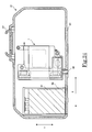
- FIG. 23 is illustrative of an imaging apparatus including the image shake corrector according to this embodiment of the invention
- FIG. 24 is illustrative of the image shake corrector and the like in the imaging apparatus.
- a digital camera 80 operating as the imaging apparatus including the image shake corrector 1 according to one embodiment of the invention is built up of a camera body 81 and a lens unit 82 comprising a taking lens L interchangeably attached to the camera body 81 , as shown in FIGS. 23 and 24 .
- an axis of light incident from the taking lens L on the camera body 81 is indicated by ⁇ , and an object side with respect to the optical axis ⁇ direction is defined as forward (front side) while an imaging side is defined as backward (back side).
- the left-and-right direction as viewed from forward in an ordinary taking state is defined as the X-direction that is the first direction
- the vertical direction is defined as the Y-direction that is the second direction.
- the X-direction that is the first direction and the Y-direction that is the second direction correspond to the X- and Y-directions that are the first and second directions with respect to the image shake corrector 1 .
- the camera body 81 comprises an outer casing 83 that serves also as a camera proper for encasing members forming the digital camera 80 in it, and further includes a ring-like mount 84 for interchangeably attaching the lens unit 82 to a front position on the optical axis ⁇ .
- the outer casing 83 is also provided with a grip (not shown) that is positioned leftward as viewed from forward and held by the right hand of an operator as images are taken. Located on top of this grip are a variety of switches and buttons such as a release button.
- the camera body 81 further comprises a battery chamber 92 within the outer casing 83 for receiving batteries 91 in it, and in the rear of the battery chamber 92 there is a circuit board (not shown) and the like located, said circuit board having on it control circuits for implementing control over the camera, image processing, compression processing, data storage processing and the like, an SDRAM or other memory, a power source circuit, etc. Further, the camera body 81 has a built-in gyro-sensor (not shown) for detecting shaking of the camera body 81 .
- the camera body 81 comprises a liquid crystal panel 86 on the back side of the outer casing 83 , which panel includes a panel display window 85 , as shown in FIGS. 23 and 24 .
- This liquid crystal panel 86 is a TFT (thin-film transistor) type of rectangular display panel that displays as images a variety of information such as settings and events in addition to the taken images.
- a hot shoe 87 located for attachment of an optical finder, an electronic view finder, an outward flash, a microphone, and such.
- the imaging unit 89 comprises the image shake prevention apparatus 1 that supports an imaging device 36 such as a CCD or CMOS sensor on the XY plane in a displaceable manner, with a voice coil motor used as an actuator.
- This image shake prevention apparatus 1 operates such that the detected shaking-direction force is cancelled out on the basis of a signal from a shake detector.
- the imaging device 36 has a rectangular light-reception surface whose long side lies along the X-direction, and the outer casing 83 is provided on its bottom surface with a threaded portion 90 for receiving a tripod.
- FIG. 25 is a block diagram illustrative of the internal circuits of a main portion of the digital camera 80 according to one embodiment of the invention.
- processing means are typically made up of a CDS/ADC portion 124 , a temporal storage memory 117 and an image processing portion 118 , and a storage means is typically made up of a storage medium.
- the digital camera 80 includes an operating portion 112 , a control portion 113 connected to the operating portion 112 , an imaging drive circuit 116 and a temporal storage memory 117 connected to the control signal output port of the control portion 113 via buses 114 and 115 , an image processing portion 118 , a storage medium portion 119 , a display portion 120 , and a preset information storage memory portion 121 .
- the temporal storage memory 117 , image processing portion 118 , storage medium portion 119 , display portion 120 and preset storage memory portion 121 are designed such that data are mutually entered in or produced out from them via a bus 122 , and the imaging drive circuit 116 is connected with the imaging device 36 and CDS/ADC portion 124 .
- the operating portion 112 includes various input buttons and switches, through which event information entered (by a camera operator) from outside is notified to the control portion 113 .
- the control portion 113 is a central computing unit that is made up of typically a CPU and has a built-in program memory (not shown): according to the program loaded in that program memory, it has control over the digital camera 80 .
- the CCD 36 is an imaging device that is driven and controlled by the imaging drive circuit 116 , and converts or transforms light quantity per pixel of the object image formed through the imaging optical system 141 into electric signals that are in turn sent out to the CDS/ADC portion 124 .
- the CDS/ADC portion 124 is a circuit that amplifies electrical signals entered from the imaging device 36 and subjects them to analog-to-digital conversion so that image raw data (Bayer data: hereinafter called the RAW data) subjected only to amplification and digital conversion are sent out to the temporal storage memory 117 .
- image raw data Bayer data: hereinafter called the RAW data
- the temporal storage memory 117 is a buffer made up of typically an SDRAM: it is a memory device for temporal storage of the RAW data produced out from the CDS/ADC portion 124 .
- the image processing portion 118 is a circuit that reads out the RAW data stored in the temporal storage memory 117 or the RAW data stored in the storage medium portion 119 thereby electrically implementing various forms of processing including distortion correction, based on an image quality parameter instructed by the control portion 113 .
- the storage medium portion 119 detachably receives a card type or stick type recording medium comprising typically a flash memory so that the RAW data transferred from the temporal storage memory 117 or image data processed at the image processing portion 118 are recorded and held in that flash memory.
- the display portion 120 includes a liquid crystal display monitor or the like to display the taken RAW data or image data, operating menus or the like on it.
- the preset information storage memory portion 121 includes a ROM portion having various image quality parameters previously loaded in it, and a RAM portion for storing an image quality parameter read out from that ROM portion by entering operation of the operating portion 112 .
- the inventive image shake corrector may be used with the thus assembled digital camera 80 thereby achieving a small-format imaging apparatus well fit for taking moving images.
Applications Claiming Priority (3)
| Application Number | Priority Date | Filing Date | Title |
|---|---|---|---|
| JP2012073252A JP5259851B1 (ja) | 2012-03-28 | 2012-03-28 | 位置制御装置 |
| JP2012-073252 | 2012-03-28 | ||
| PCT/JP2012/083402 WO2013145481A1 (ja) | 2012-03-28 | 2012-12-25 | 位置制御装置 |
Related Parent Applications (1)
| Application Number | Title | Priority Date | Filing Date |
|---|---|---|---|
| PCT/JP2012/083402 Continuation WO2013145481A1 (ja) | 2012-03-28 | 2012-12-25 | 位置制御装置 |
Publications (2)
| Publication Number | Publication Date |
|---|---|
| US20130300336A1 US20130300336A1 (en) | 2013-11-14 |
| US8884570B2 true US8884570B2 (en) | 2014-11-11 |
Family
ID=49052970
Family Applications (1)
| Application Number | Title | Priority Date | Filing Date |
|---|---|---|---|
| US13/943,102 Active US8884570B2 (en) | 2012-03-28 | 2013-07-16 | Position control system |
Country Status (4)
| Country | Link |
|---|---|
| US (1) | US8884570B2 (ja) |
| JP (1) | JP5259851B1 (ja) |
| CN (1) | CN103443702B (ja) |
| WO (1) | WO2013145481A1 (ja) |
Families Citing this family (19)
| Publication number | Priority date | Publication date | Assignee | Title |
|---|---|---|---|---|
| WO2013046816A1 (ja) * | 2011-09-29 | 2013-04-04 | オリンパス株式会社 | 像振れ補正装置及びそれを備えた撮像装置 |
| KR102151763B1 (ko) * | 2013-06-03 | 2020-09-04 | 삼성전자주식회사 | 손떨림 보정장치 및 이를 포함하는 디지털 촬영장치 |
| KR102125558B1 (ko) * | 2013-08-19 | 2020-06-22 | 삼성전자주식회사 | 카메라 모듈, 이에 사용되는 위치 검출 장치 및 위치 검출 방법 |
| US9560247B2 (en) * | 2014-05-30 | 2017-01-31 | Apple Inc. | Optical image stabilization compensations |
| KR102176284B1 (ko) * | 2015-04-08 | 2020-11-09 | 삼성전기주식회사 | 디지털 촬영시스템 및 그 제어방법 |
| JP6338769B2 (ja) * | 2015-04-09 | 2018-06-06 | 三菱電機株式会社 | アクチュエータの制御装置、アクチュエータ、バルブ駆動装置およびアクチュエータの制御方法 |
| US10382698B2 (en) | 2015-09-30 | 2019-08-13 | Apple Inc. | Mobile zoom using multiple optical image stabilization cameras |
| JP6676936B2 (ja) * | 2015-11-16 | 2020-04-08 | リコーイメージング株式会社 | 撮像装置および駆動装置の制御方法 |
| US10123004B2 (en) * | 2016-01-28 | 2018-11-06 | Olympus Corporation | Image stabilization apparatus and image pickup apparatus using image stabilization apparatus |
| JP6716281B2 (ja) * | 2016-02-19 | 2020-07-01 | キヤノン株式会社 | 駆動装置、その制御方法、および制御プログラム、並びに撮像装置 |
| JP6662127B2 (ja) * | 2016-03-15 | 2020-03-11 | 株式会社リコー | 画像生成ユニット及び画像投影装置 |
| TWI595739B (zh) * | 2016-10-27 | 2017-08-11 | 動運科學技術有限公司 | 音圈馬達驅動控制裝置及音圈馬達驅動控制方法 |
| CN108062114A (zh) * | 2016-11-08 | 2018-05-22 | 广州奥睿智能科技有限公司 | 舵机控制方法、控制系统和舵机 |
| JP6930049B2 (ja) * | 2017-01-16 | 2021-09-01 | Omデジタルソリューションズ株式会社 | 駆動装置及び撮像装置の制御方法 |
| CN112954176B (zh) * | 2017-03-22 | 2023-04-18 | 松下知识产权经营株式会社 | 摄像元件驱动装置、及摄像元件驱动装置的制造方法 |
| CN109995995A (zh) * | 2017-12-29 | 2019-07-09 | 杭州海康威视系统技术有限公司 | 摄像装置的控制方法、控制器和系统 |
| TWI677181B (zh) | 2018-11-08 | 2019-11-11 | 財團法人工業技術研究院 | 多軸線圈共接式音圈馬達驅動裝置 |
| CN111478631B (zh) * | 2020-05-25 | 2021-08-17 | 南京工程学院 | 一种用于贴片机的音圈电机控制系统及控制方法 |
| KR102495683B1 (ko) * | 2021-04-09 | 2023-02-06 | 주식회사 지니틱스 | 보이스 코일 모터 액추에이터의 안정성 평가를 위한 주파수 응답 특성 측정방법 및 이를 위한 장치 |
Citations (10)
| Publication number | Priority date | Publication date | Assignee | Title |
|---|---|---|---|---|
| JPH1164914A (ja) | 1997-08-25 | 1999-03-05 | Nikon Corp | ブレ補正装置 |
| JP2000066258A (ja) | 1998-08-21 | 2000-03-03 | Nikon Corp | ブレ補正装置及びブレ補正方法 |
| US6208109B1 (en) * | 1996-08-19 | 2001-03-27 | Hiroyuki Yamai | Synchronous motor driving method, compressor driving method, device for the methods, and brushless DC motor driving device |
| US6307702B1 (en) * | 1998-07-03 | 2001-10-23 | Fujitsu Limited | Method of writing servo tracks on magnetic disc and device for the same |
| JP2006227653A (ja) | 2006-05-19 | 2006-08-31 | Nikon Corp | 手ぶれ補正機能を有するカメラ |
| US20070297055A1 (en) * | 2006-06-21 | 2007-12-27 | Pentax Corporation | Supporting mechanism |
| US7783179B2 (en) * | 2007-02-01 | 2010-08-24 | Sony Corporation | Image blur correction apparatus, lens barrel, and image capture apparatus |
| JP2011075834A (ja) | 2009-09-30 | 2011-04-14 | Nikon Corp | ブレ補正装置及び光学機器 |
| JP2011115035A (ja) | 2009-11-30 | 2011-06-09 | Rohm Co Ltd | モータ制御回路および制御方法ならびにそれらを用いた撮像機能付き電子機器 |
| US20130063615A1 (en) * | 2011-09-13 | 2013-03-14 | Canon Kabushiki Kaisha | Image stabilization apparatus, image capture apparatus comprising the same, and controlling methods thereof |
Family Cites Families (5)
| Publication number | Priority date | Publication date | Assignee | Title |
|---|---|---|---|---|
| JP2007248782A (ja) * | 2006-03-15 | 2007-09-27 | Olympus Imaging Corp | 焦点調節装置およびカメラ |
| JP2008199486A (ja) * | 2007-02-15 | 2008-08-28 | Olympus Imaging Corp | 一眼レフレックス型の電子撮像装置 |
| JP2009047956A (ja) * | 2007-08-21 | 2009-03-05 | Sony Corp | 撮像装置 |
| JP4582152B2 (ja) * | 2008-01-25 | 2010-11-17 | ソニー株式会社 | 撮像装置、および撮像装置制御方法、並びにコンピュータ・プログラム |
| JP5419647B2 (ja) * | 2009-11-16 | 2014-02-19 | キヤノン株式会社 | 像振れ補正装置およびそれを備えた撮像装置、像振れ補正装置の制御方法 |
-
2012
- 2012-03-28 JP JP2012073252A patent/JP5259851B1/ja active Active
- 2012-12-25 CN CN201280010031.4A patent/CN103443702B/zh not_active Expired - Fee Related
- 2012-12-25 WO PCT/JP2012/083402 patent/WO2013145481A1/ja active Application Filing
-
2013
- 2013-07-16 US US13/943,102 patent/US8884570B2/en active Active
Patent Citations (11)
| Publication number | Priority date | Publication date | Assignee | Title |
|---|---|---|---|---|
| US6208109B1 (en) * | 1996-08-19 | 2001-03-27 | Hiroyuki Yamai | Synchronous motor driving method, compressor driving method, device for the methods, and brushless DC motor driving device |
| JPH1164914A (ja) | 1997-08-25 | 1999-03-05 | Nikon Corp | ブレ補正装置 |
| US6307702B1 (en) * | 1998-07-03 | 2001-10-23 | Fujitsu Limited | Method of writing servo tracks on magnetic disc and device for the same |
| JP2000066258A (ja) | 1998-08-21 | 2000-03-03 | Nikon Corp | ブレ補正装置及びブレ補正方法 |
| JP2006227653A (ja) | 2006-05-19 | 2006-08-31 | Nikon Corp | 手ぶれ補正機能を有するカメラ |
| US20070297055A1 (en) * | 2006-06-21 | 2007-12-27 | Pentax Corporation | Supporting mechanism |
| US7783179B2 (en) * | 2007-02-01 | 2010-08-24 | Sony Corporation | Image blur correction apparatus, lens barrel, and image capture apparatus |
| JP2011075834A (ja) | 2009-09-30 | 2011-04-14 | Nikon Corp | ブレ補正装置及び光学機器 |
| JP2011115035A (ja) | 2009-11-30 | 2011-06-09 | Rohm Co Ltd | モータ制御回路および制御方法ならびにそれらを用いた撮像機能付き電子機器 |
| US20110292226A1 (en) | 2009-11-30 | 2011-12-01 | Rohm Co., Ltd. | Control circuit and control method for motor |
| US20130063615A1 (en) * | 2011-09-13 | 2013-03-14 | Canon Kabushiki Kaisha | Image stabilization apparatus, image capture apparatus comprising the same, and controlling methods thereof |
Non-Patent Citations (1)
| Title |
|---|
| International Search Report dated Jan. 29, 2013 issued in PCT/JP2012/083402. |
Also Published As
| Publication number | Publication date |
|---|---|
| CN103443702A (zh) | 2013-12-11 |
| US20130300336A1 (en) | 2013-11-14 |
| JP5259851B1 (ja) | 2013-08-07 |
| CN103443702B (zh) | 2015-06-03 |
| WO2013145481A1 (ja) | 2013-10-03 |
| JP2013205549A (ja) | 2013-10-07 |
Similar Documents
| Publication | Publication Date | Title |
|---|---|---|
| US8884570B2 (en) | Position control system | |
| US9678493B2 (en) | Position detection apparatus and position control apparatus | |
| US9516232B2 (en) | Moving member control apparatus and imaging apparatus incorporating the same | |
| US9332184B2 (en) | Image-shake correction apparatus and imaging apparatus incorporating the same | |
| JP5914716B1 (ja) | 撮像装置 | |
| US8031240B2 (en) | Imaging device | |
| US8111295B2 (en) | Image stabilizer and optical instrument therewith | |
| US20080111890A1 (en) | Electromagnetic driving apparatus and optical apparatus | |
| JP6099404B2 (ja) | ぶれ補正装置及びそれを備えた撮像装置 | |
| JP2019109426A (ja) | 撮像装置およびその制御方法 | |
| US9031395B2 (en) | Moving member control apparatus and imaging apparatus incorporating the same | |
| US10313590B2 (en) | Drive device and method for controlling the drive device | |
| JP6614852B2 (ja) | 撮像装置 | |
| JP4558608B2 (ja) | 撮像装置および撮像装置における接続方法 | |
| KR101329741B1 (ko) | 손떨림 보정 제어 방법 및 손떨림 보정 제어 장치 | |
| JP5855474B2 (ja) | レンズ鏡筒 | |
| JP2014137380A (ja) | ぶれ補正装置及びそれを備えた撮像装置 | |
| JP5788280B2 (ja) | 像振れ補正装置及びそれを備えた撮像装置 | |
| WO2024070587A1 (ja) | ブレ補正装置 | |
| JP2010010796A (ja) | カメラ | |
| JP2008275767A (ja) | レンズ鏡筒および撮像装置 |
Legal Events
| Date | Code | Title | Description |
|---|---|---|---|
| AS | Assignment |
Owner name: OLYMPUS CORPORATION, JAPAN Free format text: ASSIGNMENT OF ASSIGNORS INTEREST;ASSIGNORS:ISHIKAWA, TAKASHI;HASHIMOTO, YUKIE;REEL/FRAME:030806/0197 Effective date: 20130613 |
|
| STCF | Information on status: patent grant |
Free format text: PATENTED CASE |
|
| FEPP | Fee payment procedure |
Free format text: PAYOR NUMBER ASSIGNED (ORIGINAL EVENT CODE: ASPN); ENTITY STATUS OF PATENT OWNER: LARGE ENTITY |
|
| AS | Assignment |
Owner name: OLYMPUS CORPORATION, JAPAN Free format text: CHANGE OF ADDRESS;ASSIGNOR:OLYMPUS CORPORATION;REEL/FRAME:039344/0502 Effective date: 20160401 |
|
| MAFP | Maintenance fee payment |
Free format text: PAYMENT OF MAINTENANCE FEE, 4TH YEAR, LARGE ENTITY (ORIGINAL EVENT CODE: M1551) Year of fee payment: 4 |
|
| AS | Assignment |
Owner name: OM DIGITAL SOLUTIONS CORPORATION, JAPAN Free format text: CHANGE OF NAME;ASSIGNOR:OLYMPUS CORPORATION;REEL/FRAME:058152/0131 Effective date: 20210730 |
|
| MAFP | Maintenance fee payment |
Free format text: PAYMENT OF MAINTENANCE FEE, 8TH YEAR, LARGE ENTITY (ORIGINAL EVENT CODE: M1552); ENTITY STATUS OF PATENT OWNER: LARGE ENTITY Year of fee payment: 8 |