US8308150B2 - Coil spring for vehicle suspension and method for manufacturing the same - Google Patents
Coil spring for vehicle suspension and method for manufacturing the same Download PDFInfo
- Publication number
- US8308150B2 US8308150B2 US12/732,450 US73245010A US8308150B2 US 8308150 B2 US8308150 B2 US 8308150B2 US 73245010 A US73245010 A US 73245010A US 8308150 B2 US8308150 B2 US 8308150B2
- Authority
- US
- United States
- Prior art keywords
- residual stress
- shot
- spring
- compressive residual
- spring wire
- Prior art date
- Legal status (The legal status is an assumption and is not a legal conclusion. Google has not performed a legal analysis and makes no representation as to the accuracy of the status listed.)
- Active
Links
Images




Classifications
-
- B—PERFORMING OPERATIONS; TRANSPORTING
- B24—GRINDING; POLISHING
- B24C—ABRASIVE OR RELATED BLASTING WITH PARTICULATE MATERIAL
- B24C1/00—Methods for use of abrasive blasting for producing particular effects; Use of auxiliary equipment in connection with such methods
- B24C1/10—Methods for use of abrasive blasting for producing particular effects; Use of auxiliary equipment in connection with such methods for compacting surfaces, e.g. shot-peening
-
- B—PERFORMING OPERATIONS; TRANSPORTING
- B24—GRINDING; POLISHING
- B24C—ABRASIVE OR RELATED BLASTING WITH PARTICULATE MATERIAL
- B24C11/00—Selection of abrasive materials or additives for abrasive blasts
-
- C—CHEMISTRY; METALLURGY
- C21—METALLURGY OF IRON
- C21D—MODIFYING THE PHYSICAL STRUCTURE OF FERROUS METALS; GENERAL DEVICES FOR HEAT TREATMENT OF FERROUS OR NON-FERROUS METALS OR ALLOYS; MAKING METAL MALLEABLE, e.g. BY DECARBURISATION OR TEMPERING
- C21D7/00—Modifying the physical properties of iron or steel by deformation
- C21D7/02—Modifying the physical properties of iron or steel by deformation by cold working
- C21D7/04—Modifying the physical properties of iron or steel by deformation by cold working of the surface
- C21D7/06—Modifying the physical properties of iron or steel by deformation by cold working of the surface by shot-peening or the like
-
- C—CHEMISTRY; METALLURGY
- C21—METALLURGY OF IRON
- C21D—MODIFYING THE PHYSICAL STRUCTURE OF FERROUS METALS; GENERAL DEVICES FOR HEAT TREATMENT OF FERROUS OR NON-FERROUS METALS OR ALLOYS; MAKING METAL MALLEABLE, e.g. BY DECARBURISATION OR TEMPERING
- C21D9/00—Heat treatment, e.g. annealing, hardening, quenching or tempering, adapted for particular articles; Furnaces therefor
- C21D9/02—Heat treatment, e.g. annealing, hardening, quenching or tempering, adapted for particular articles; Furnaces therefor for springs
-
- F—MECHANICAL ENGINEERING; LIGHTING; HEATING; WEAPONS; BLASTING
- F16—ENGINEERING ELEMENTS AND UNITS; GENERAL MEASURES FOR PRODUCING AND MAINTAINING EFFECTIVE FUNCTIONING OF MACHINES OR INSTALLATIONS; THERMAL INSULATION IN GENERAL
- F16F—SPRINGS; SHOCK-ABSORBERS; MEANS FOR DAMPING VIBRATION
- F16F1/00—Springs
- F16F1/02—Springs made of steel or other material having low internal friction; Wound, torsion, leaf, cup, ring or the like springs, the material of the spring not being relevant
- F16F1/04—Wound springs
-
- F—MECHANICAL ENGINEERING; LIGHTING; HEATING; WEAPONS; BLASTING
- F16—ENGINEERING ELEMENTS AND UNITS; GENERAL MEASURES FOR PRODUCING AND MAINTAINING EFFECTIVE FUNCTIONING OF MACHINES OR INSTALLATIONS; THERMAL INSULATION IN GENERAL
- F16F—SPRINGS; SHOCK-ABSORBERS; MEANS FOR DAMPING VIBRATION
- F16F1/00—Springs
- F16F1/02—Springs made of steel or other material having low internal friction; Wound, torsion, leaf, cup, ring or the like springs, the material of the spring not being relevant
- F16F1/04—Wound springs
- F16F1/06—Wound springs with turns lying in cylindrical surfaces
-
- F—MECHANICAL ENGINEERING; LIGHTING; HEATING; WEAPONS; BLASTING
- F16—ENGINEERING ELEMENTS AND UNITS; GENERAL MEASURES FOR PRODUCING AND MAINTAINING EFFECTIVE FUNCTIONING OF MACHINES OR INSTALLATIONS; THERMAL INSULATION IN GENERAL
- F16F—SPRINGS; SHOCK-ABSORBERS; MEANS FOR DAMPING VIBRATION
- F16F2226/00—Manufacturing; Treatments
- F16F2226/02—Surface treatments
-
- Y—GENERAL TAGGING OF NEW TECHNOLOGICAL DEVELOPMENTS; GENERAL TAGGING OF CROSS-SECTIONAL TECHNOLOGIES SPANNING OVER SEVERAL SECTIONS OF THE IPC; TECHNICAL SUBJECTS COVERED BY FORMER USPC CROSS-REFERENCE ART COLLECTIONS [XRACs] AND DIGESTS
- Y10—TECHNICAL SUBJECTS COVERED BY FORMER USPC
- Y10T—TECHNICAL SUBJECTS COVERED BY FORMER US CLASSIFICATION
- Y10T29/00—Metal working
- Y10T29/47—Burnishing
- Y10T29/479—Burnishing by shot peening or blasting
-
- Y—GENERAL TAGGING OF NEW TECHNOLOGICAL DEVELOPMENTS; GENERAL TAGGING OF CROSS-SECTIONAL TECHNOLOGIES SPANNING OVER SEVERAL SECTIONS OF THE IPC; TECHNICAL SUBJECTS COVERED BY FORMER USPC CROSS-REFERENCE ART COLLECTIONS [XRACs] AND DIGESTS
- Y10—TECHNICAL SUBJECTS COVERED BY FORMER USPC
- Y10T—TECHNICAL SUBJECTS COVERED BY FORMER US CLASSIFICATION
- Y10T29/00—Metal working
- Y10T29/49—Method of mechanical manufacture
- Y10T29/49609—Spring making
-
- Y—GENERAL TAGGING OF NEW TECHNOLOGICAL DEVELOPMENTS; GENERAL TAGGING OF CROSS-SECTIONAL TECHNOLOGIES SPANNING OVER SEVERAL SECTIONS OF THE IPC; TECHNICAL SUBJECTS COVERED BY FORMER USPC CROSS-REFERENCE ART COLLECTIONS [XRACs] AND DIGESTS
- Y10—TECHNICAL SUBJECTS COVERED BY FORMER USPC
- Y10T—TECHNICAL SUBJECTS COVERED BY FORMER US CLASSIFICATION
- Y10T29/00—Metal working
- Y10T29/49—Method of mechanical manufacture
- Y10T29/49609—Spring making
- Y10T29/49611—Spring making for vehicle or clutch
Definitions
- the present invention relates to a coil spring for vehicle suspension used for a suspension mechanism of a vehicle such as an automobile or the like, excellent in corrosion durability, and method for manufacturing the same.
- a coil spring for suspension mechanism is subject to an influence of an antifreeze agent scattered on a road in the wintertime or the like.
- the antifreeze agent contains salt, and hence the agent promotes corrosion of the surface of the coil spring constituted of spring steel.
- a corrosion pit etch pit
- a corrosion pit 2 particularly exerts a great influence upon the durability of the coil spring.
- part of the surface 1 a of the spring wire 1 is corroded to form a hole-like shape by moisture or salt, whereby a corrosion pit 2 is formed.
- the shape of the corrosion pit 2 varies, there is even a corrosion pit 2 having a cross section as schematically shown in, for example, FIG. 12 .
- the coil spring for suspension be used at higher stress in order to effect weight reduction of a vehicle.
- compressive residual stress is imparted to the vicinity of the surface of the coil spring, and the durability thereof is enhanced.
- multistage shot peening is disclosed. In the multistage shot peening, shot peening is carried cut a plurality of times in a dividing mariner.
- stress peening and warm peening are known.
- the shot is applied to the coil spring in a state where the spring is compressed.
- the warm peening the shot is applied to the coil spring in a state where the spring is heated at a temperature of about 250° C.
- the stress peening or warm peening it is possible to cause compressive residual stress to appear in a region up to a deep position in the material.
- the stress peening requires equipments configured to compress the coil spring.
- the shot is applied to the coil spring in a state where the coil spring is compressed, and hence gaps between spring wire parts become small. Accordingly, there is a problem that it is hard for the shot to hit the inside of the coil spring or positions between the spring wire parts.
- the corrosion resistance of the coil spring is improved by adding an alloy element such as Ni, Cr, Mo or the like to the spring steel.
- an alloy element such as Ni, Cr, Mo or the like
- the spring steel containing such an alloy element is expensive, this being a cause making the cost of the coil spring high.
- the size of the corrosion pit reaches the permissible pit depth, there is the possibility of the coil spring being broken while making a fatigue crack occurring at a bottom part or the like of the corrosion pit a starting point.
- An object of the present invention is to provide a coil spring for vehicle suspension capable of enhancing the corrosion durability, and being used at higher stress, and method for manufacturing the same.
- a coil spring for vehicle suspension of the present invention is that made of a spring wire to which compressive residual stress is imparted by shot peening and comprises a residual stress increase part, residual stress peak part, and residual stress decrease part.
- the residual stress increase part the compressive residual stress increases from the surface of the spring wire in a depth direction.
- the residual stress peak part the compressive residual stress becomes the maximum.
- the residual stress decrease part the compressive residual stress decreases from the residual stress peak part in the depth direction of the spring wire.
- a part comprising the compressive residual stress magnitude of which is equivalent to the magnitude of the compressive residual stress at the surface of the spring wire exists at a position at a depth exceeding the permissible pit depth of the spring wire.
- the coil spring for vehicle suspension of the present invention even when the corrosion pit grows to a position near the permissible pit depth, it is possible to prevent a fatigue crack from occurring at the bottom part or the like of the corrosion pit, and enhance the corrosion durability. As a result of this, it becomes possible to use the suspension coil spring for vehicle suspension at higher stress, and effect weight reduction of the vehicle.
- compressive residual stress of ⁇ 400 MPa or more (implying an absolute value of 400 MPa or more, the same is true of the following) be imparted to a region from the surface of the spring wire to a position at the permissible pit depth.
- the hardness of the spring wire the hardness of 50 to 56 HRC is recommendable.
- a position which is located deeper than the residual stress peak part, and at which the compressive residual stress begins to largely lower be located deeper than 0.2 mm from the surface of the spring.
- compressive residual stress of ⁇ 400 MPa or more be imparted to a region from the surface to a position at a depth of 0.3 mm.
- a method for manufacturing a coil spring for vehicle suspension of the present invention comprises a bending process, first shot peening process, and second shot peening process.
- a spring wire constituted of a spring steel is formed into a helical shape.
- compressive residual stress is imparted to the spring wire by applying the spring wire with the first shot of a shot size of 1.0 mm or more.
- the second shot peening process is carried out after the first shot peening process.
- the spring wire is applied with the second shot smaller in shot size than the first shot.
- the manufacturing method of the present invention it is possible to cause a high level of compressive residual stress effective in preventing occurrence of a fatigue crack and development of the crack to appear in a region from the surface of the spring wire to a position at a depth exceeding the permissible pit depth. Furthermore, it is possible to make a difference between the compressive residual stress near the surface of the spring wire and compressive residual stress near the bottom part of the corrosion pit small. As a result of this, it is possible to obtain compressive residual stress distribution highly effective in preventing a fatigue crack from occurring in the corrosion pit.
- the present invention is recommendable to carry out the first shot peening process and second shot peening process in a state where the spring wire is kept at a processing temperature of 150 to 350° C.
- the processing temperature in the first shot peening process is higher than the processing temperature in the second shot peening process. Further, it is advisable to make the kinetic energy of the first shot greater than the kinetic energy of the second shot.
- FIG. 1 is a side view of part of an automobile provided with a coil spring for suspension according to an embodiment of the present invention
- FIG. 2 is a perspective view of a coil spring for suspension shown in FIG. 1 ;
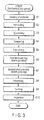
- FIG. 3 is a flowchart showing an example of manufacturing processes of the coil spring for suspension shown in FIG. 2 ;
- FIG. 4 is a flowchart showing another example of manufacturing processes of the coil spring for suspension shown in FIG. 2 ;
- FIG. 5 is a graph showing the compressive residual stress distribution of example 1 according to the present invention.
- FIG. 6 is a graph showing the compressive residual stress distribution of example 2 according to the present invention.
- FIG. 7 is a graph showing the compressive residual stress distribution of example 3 according to the present invention.
- FIG. 8 is a graph showing the compressive residual stress distribution of comparative example 1;
- FIG. 9 is a graph showing the corrosion life of each of examples 1 and 2 according to the present invention, and comparative example 1;
- FIG. 10 is a graph showing the corrosion life of each of examples 4 and 5 according to the present invention, and comparative example 2;
- FIG. 11 is a cross-sectional view schematically showing an example of a corrosion pit
- FIG. 12 is a cross-sectional view schematically showing another example of a corrosion pit.
- FIG. 13 is a cross-sectional view schematically showing a corrosion pit in which a crack has occurred.
- a coil spring for vehicle suspension according to an embodiment of the present invention, and method for manufacturing the coil spring will be described below with reference to the drawings.
- a suspension mechanism 11 of a vehicle 10 shown in FIG. 1 is provided with a coil spring 12 for vehicle suspension (hereinafter referred to simply as a coil spring 12 ), and shock absorber 13 .
- a coil spring 12 for vehicle suspension hereinafter referred to simply as a coil spring 12
- shock absorber 13 In the coil spring 12 shown in FIG. 2 , a spring wire 20 is formed into a helical shape.
- the coil spring 12 elastically supports the load of the vehicle 10 in a state where the spring 12 is compressed in the direction of the axis X.
- An example of the coil spring 12 is a cylindrical coil spring.
- An example of a wire diameter d (shown in FIG. 2 ) of the spring wire 20 is 12.5 mm.
- An average coil diameter D is 110.0 mm, free length (length at no load) is 382 mm, number of active turns is 5.39, and spring constant is 33.3 N/mm.
- the main stream of the wire diameter of the coil spring 12 is 8 to 21 mm, diameters other than the above may also be employed.
- coil springs of various forms such as a barrel-shaped spring, double headed conical spring, tapered coil spring, variable pitch coil spring, load axis control coil spring, and the like may also be employed.
- the type of steel of the spring wire 20 is high corrosion resistant spring steel (in this description, referred to as spring steel S for convenience).
- the spring steel S is of a steel type enhanced in corrosion resistance, and the chemical components (mass %) thereof are C: 0.41, Si: 1.73, Mn: 0.17, Ni: 0.53, Cr: 1.05, V: 0.163, Ti: 0.056, Cu: 0.21, and Fe: remnant.
- FIG. 3 shows manufacturing processes of a hot-formed coil spring.
- a heating process S 1 a spring wire which is a material for the coil spring is heated at an austenitizing temperature (higher than A 3 transformation point, and lower than 1150° C.).
- the heated spring wire is bent into a helical shape in a bending process (coiling process) S 2 .
- the coiled spring wire is subjected to heat treatment such as a quenching process S 3 , tempering process S 4 , and the like.
- the spring wire is thermal refined by the heat treatment so that the hardness of 50 to 56 HRC can be obtained.
- a coil spring of design maximum stress of 1300 MPa is thermal refined so that hardness of 54.5 HRC can be obtained.
- a load in the axial direction of the coil spring is applied to the coil spring for a predetermined time.
- the hot setting process S 5 is carried out as warm working by utilizing the remaining heat after the heat treatment.
- a first shot peening process S 6 is carried out.
- the first shot (cut wire pieces made of iron) having a shot size (grain size) of 1.0 mm is used.
- the spring wire is applied with the first shot at a processing temperature of 230° C., at a velocity of 76.7 m/s, and with kinetic energy of 12.11 ⁇ 10 ⁇ 3 J.
- compressive residual stress appears in a wide region from the surface of the spring wire in the depth direction.
- the compressive residual stress distribution will be described later in detail. It is desirable that the surface roughness of the spring wire obtained by the first shot peening process S 6 be 75 ⁇ m or less.
- the velocity of the shot is a value obtained by multiplying the circumferential velocity obtained from the diameter of the impeller of the shot peening machine, and rotational speed of the impeller by 1.3.
- a second shot peening process S 7 is carried out.
- the second shot smaller in size than the first shot is used.
- the shot size of the second shot is 0.67 mm.
- the spring wire is applied with the second shot at a processing temperature of 200° C., at a velocity of 46 m/s, and with kinetic energy of 1.31 ⁇ 10 ⁇ 3 J.
- the second shot peening process S 7 the second shot smaller in size than that of the first shot in the first shot peening 56 is used. Furthermore, the velocity of the second shot in the second shot peening process S 7 is smaller than the velocity of the first shot in the first shot peening process S 6 . As a result of this, the large surface roughness of the spring wire after the first shot peening process S 6 can be made small by the second shot peening process S 7 , and the surface state of the spring wire is improved.
- the spring wire may be applied with the second shot having a shot size of 0.40 mm at a processing temperature of 200° C., at a velocity of 86.7 m/s, and with kinetic energy of 0.99 ⁇ 10 ⁇ 3 J.
- Table 1 shows data in which kinetic energy values of the shots are compared with each other in terms of shot peening conditions.
- the kinetic energy becomes larger even if the same velocity is employed.
- the large-grain shot having a shot size of 1 mm the kinetic energy becomes about 1.5 times that of the shot having a shot size of 0.87 mm.
- the large-grain shot having a shot size of 1.1 mm the kinetic energy becomes about twice that of the shot having the shot size of 0.87 mm.
- the small-grain shot having a shot size of 0.67 mm the kinetic energy becomes less than half that of the shot having the shot size of 0.87 mm.
- the shot having a shot size of 0.4 mm the kinetic energy becomes less than that of the shot having the shot size of 0.67 mm even if the velocity is made about twice.
- the kinetic energy of the first shot of the first shot peening process S 6 is made greater than the kinetic energy of the second shot of the second shot peening process S 7 .
- the processing temperature in each of the first shot peening process 56 and second shot peening process S 7 a temperature within a range of 150 to 350° C. is suitable. That is, these processes are warm peening (hot peening) processes utilizing the remaining heat after the heat treatment. Furthermore, the second shot peening process 67 is carried out at a processing temperature lower than the first shot peening process S 6 .
- a presetting process S 8 and painting process S 9 are carried out. Thereafter, in order to inspect the external appearance and characteristics of the coil spring, an inspection process S 10 is conducted. It should be noted that the presetting process S 8 may be omitted.
- FIG. 4 shows a manufacturing process of a case where the coil spring is coiled in the cold working.
- the spring wire before being subjected to the coiling process is subjected in advance to heat treatment such as a quenching process S 11 , tempering process 512 , and the like.
- the spring wire is formed into a helical shape in a bending process (coiling process) S 13 to be carried out as cold working.
- a stress relief annealing process S 14 the coil spring is left as it is in an atmosphere of a predetermined temperature for a predetermined time, whereby the processing strain caused during the formation time is eliminated.
- the hot setting process S 5 first shot peening process S 6 , second shot peening process S 7 , presetting process S 8 , painting process S 9 , and inspection process S 10 are carried out.
- the coil spring may also be coiled in the warm working.
- the presetting process S 8 may be omitted.
- FIG. 5 shows the compressive residual stress distribution of the coil spring of example 1.
- the abscissa of FIG. 5 represents positions from the surface of the spring wire in the depth direction.
- the ordinate of FIG. 5 represents the residual stress, in accordance with the customs of the technical field, the compressive residual stress values are expressed as negative values.
- the compressive residual stress of the coil spring of example 1 includes a residual stress increase part 11 , high stress part 12 , residual stress peak part T 3 , and residual stress decrease part 14 .
- the residual stress increase part T 1 the compressive residual stress increases from the surface of the spring wire toward the inside of the spring wire in the depth direction.
- the high stress part T 2 the compressive residual stress is maintained at a high level.
- the residual stress peak part T 3 the compressive residual stress becomes the maximum.
- the residual stress decrease part T 4 the compressive residual stress decreases from the residual stress peak part T 3 in the depth direction of the spring wire.
- a part B having the compressive residual stress magnitude of which is equivalent to the magnitude of the compressive residual stress value A at the surface of the spring wire exists at a position at a depth exceeding the permissible pit depth R max of the spring wire.
- the permissible pit depth R max implies the maximum pit depth associated with the possibility of the coil spring for suspension having the compressive residual stress distribution obtained by the conventional shot peening being broken while making a fatigue crack occurring at a bottom part or the like of the corrosion pit a starting point.
- the permissible pit depth in this case is 0.25 mm.
- the part B having the compressive residual stress magnitude of which is equivalent to the magnitude of the compressive residual stress value A at the surface of the spring wire exists at a position at a depth exceeding the permissible pit depth R max of the spring wire. Furthermore, the coil spring of example 1 has compressive residual stress of ⁇ 400 MPa or more in a wide region from the surface to a position at a depth exceeding the permissible pit depth R max .
- two-stage shot peening (warm double shot peening) constituted of the first shot peening process S 6 and second shot peening process 37 is carried out. That is, by the first shot peening process S 6 of the first stage, the peak of the compressive residual stress appears at a position deep from the surface and, moreover the compressive residual stress occurs up to the deep position. Further, by the second shot peening process S 7 of the second stage, it is possible to enhance the compressive residual stress near the surface as indicated by the arrow h in FIG. 5 . In this way, it is possible to obtain the high stress part T 2 in which the compressive residual stress is maintained at a high level in a region from the vicinity of the surface to a deep position.
- the compressive residual stress value of the surface at that time is set at about ⁇ 400 MPa or more.
- the type of steel of the spring wire is the high corrosion resistant spring steel (spring steel S) identical with example 1.
- the manufacturing processes are identical with example 1 except for the size of the shot used in a first shot peening process S 6 .
- the first shot of a shot size of 1.1 mm was used in the first shot peening process S 6 .
- a second shot peening process S was carried out by using the second shot having a shot size of 0.67 mm.
- the velocity of the shot and processing temperature were identical with example 1.
- FIG. 6 shows the compressive residual stress distribution of example 2.
- the coil spring of example 2 also has, like that of example 1, a residual stress increase part T 1 , high stress part T 2 , residual stress peak part T 3 , and residual stress decrease part T 4 .
- the residual stress increase part T 1 the compressive residual stress increases from the surface of the spring wire in the depth direction.
- the high stress part T 2 the compressive residual stress is maintained at a high level.
- the residual stress peak part T 3 the compressive residual stress becomes the maximum.
- the residual stress decrease part T 4 the compressive residual stress decreases from the residual stress peak part T 3 in the depth direction of the spring wire.
- the coil spring of example 2 as in the case of example 1, a part B having the compressive residual stress magnitude of which is equivalent to the magnitude of the compressive residual stress value A at the surface of the spring wire exists at a position at a depth exceeding the permissible pit depth R max of the spring wire. Furthermore, the coil spring of example 2 has compressive residual stress of ⁇ 400 MPa or more in a wide region from the surface to a position at a depth exceeding the permissible pit depth R max .
- the type of steel of the spring wire is the high corrosion resistant spring steel (spring steel S) identical with example 1.
- the manufacturing processes are identical with example 2 except that high-frequency heating is used for heat treatment of the spring wire.
- the spring wire is heated by high-frequency heating in a quenching process S 3 , whereby the surface of the spring wire is prevented from being decarbonized.
- a quenching process S 3 whereby the surface of the spring wire is prevented from being decarbonized.
- a first shot peening process S 6 the first shot having a shot size of 1.1 mm was used.
- a second shot peening process S 7 the second shot having a shot size of 0.67 mm was used.
- the velocity of the shot and processing temperature were identical with example 1.
- FIG. 7 shows the compressive residual stress distribution of example 3.
- the coil spring of example 3 also has, like those of examples 1 and 2, a residual stress increase part T 1 , high stress part T 2 , residual stress peak part T 3 , and residual stress decrease part T 4 .
- a part B having the compressive residual stress magnitude of which is equivalent to the magnitude of the compressive residual stress value A at the surface of the spring wire exists at a position at a depth exceeding the permissible pit depth R max of the spring wire.
- the coil spring of example 3 ha-compressive residual stress of ⁇ 400 MPa or more in a wide region from the surface to a position at a depth exceeding the permissible pit depth R max .
- the steel type of SAE 9254 was used as the spring wire.
- the chemical components (mass %) of SAE 9254 are C: 0.51 to 0.59, Si: 1.20 to 1.60, Mn: 0.60 to 0.80, Cr: 0.60 to 0.80, S: 0.040 max., P: 0.030 max., and Fe: remnant.
- the manufacturing processes are identical with example 1.
- the spring wire constituted of SAE 9254 (hardness: 53.5 HRC) was subjected to a first shot peening process (velocity: 76 m/s, processing temperature: 230° C.) by using the first shot having a shot size of 1.0 mm. Thereafter, the spring wire was subjected to a second shot peening process (velocity: 46 m/s, processing temperature: 200° C.) by using the second shot having a shot size of 0.67 mm.
- the steel type of SAE 9254 was used as the spring wire, and a coil spring was manufactured by the same processes as example 2. That is, in example 5, the spring wire constituted of SAE 9254 (hardness: 53.5 HRC) was subjected to a first shot peening process (velocity: 76 m/s, processing temperature: 230° C.) by using the first shot having a shot size of 1.1 mm. Thereafter, the spring wire was subjected to a second shot peening process (velocity: 46 m/s, processing temperature: 200° C.) by using the second shot having a shot size of 0.67 mm.
- a first shot peening process velocity: 76 m/s, processing temperature: 230° C.
- a second shot peening process velocity: 46 m/s, processing temperature: 200° C.
- the high corrosion resistant spring steel (spring steel S) identical with example 1 was used.
- the manufacturing processes are common to example 1 except for the shot peening conditions.
- the spring wire in comparative example 1, in a first shot peening process, the spring wire was applied with the first shot having a shot size of 0.87 mm at a velocity of 76 m/s. The processing temperature was 230° C. Thereafter, in a second shot peening process, the spring wire was applied with the second shot having a shot size of 0.67 mm at a velocity of 46 m/s. The processing temperature was 200° C.
- FIG. 8 shows the compressive residual stress distribution of comparative example 1.
- the maximum value of the compressive residual stress of comparative example 1 bears comparison with examples 1 to 3.
- a part B′ at which the compressive residual stress equivalent to the compressive residual stress value A′ at the surface of the spring wire exists is located at a position considerably shallower than the permissible pit depth R max (0.25 mm).
- R max the permissible pit depth
- Comparative example 2 is identical with comparative example 1 except that SAE 9254 was employed as the steel type for the spring wire.
- the spring wire (hardness: 53.5 HRC) constituted of SAE 9254 was subjected to a first shot peening process (velocity: 76 m/s, processing temperature: 230° C.) by using the first shot having a shot size of 0.87 mm. Thereafter, the spring wire was subjected to a second shot peening process (velocity: 46 m/s, processing temperature: 200° C.) by using the second shot having a shot size of 0.67 mm.
- FIG. 9 shows results of corrosion fatigue tests of examples 1 and 2, and comparative example 1.
- the coil spring was subjected to test cycles each of which is constituted of subjecting the coil spring to spraying of salt water (5% NaCl) for 30 minutes, thereafter subjecting the coil spring to vibration 3000 times, and then keeping the coil spring in an environment having humidity of 95% for 23 hours until the coil spring is broken, and the total number of vibration was measured.
- the test stress was 1200 MPa.
- the corrosion life was markedly improved to 123% in comparison with the corrosion life (100%) of comparative example 1. Furthermore, in example 2, the corrosion life was largely improved further to 145%. As described above, in the coil springs of the above examples 1 and 2, the corrosion durability of the suspension coil springs was largely improved by the warm peening using the large-grain shot having a shot size of 1.0 mm or more.
- FIG. 10 shows results of corrosion fatigue tests of examples 4 and 5, and comparative example 2.
- the corrosion life of a case where the corrosion fatigue test of the coil spring of comparative example 2 is carried out at the test stress of 1100 MPa defined as 100%, and corrosion lives of cases where tests are carried out at the test stress of 1200 MPa by increasing the test stress by 100 MPa are compared with the corrosion life of above comparative example 2.
- the corrosion life was lowered to 65% in comparative example 2.
- the corrosion life of 104% which was more than the conventional one was obtained.
- the corrosion life was largely improved to 160%.
- the same tendency is in evidence irrespectively of the steel types, in many steel types including the above-mentioned high corrosion resistant spring steel (spring steel S), SAE 9254, and in, for example, the spring steel SUP7 conforming to Japanese Industrial Standards (JIS), the same result was obtained. Furthermore, according to the present invention, it is possible to enhance the corrosion durability by using an ordinarily used spring steel for a suspension coil spring, and hence an effect of making it possible to prevent the material cost of the coil spring from becoming high is also obtained. It is possible to apply the coil spring according to the present invention to suspension mechanisms of various vehicles including automobiles.
Landscapes
- Engineering & Computer Science (AREA)
- Chemical & Material Sciences (AREA)
- Mechanical Engineering (AREA)
- General Engineering & Computer Science (AREA)
- Crystallography & Structural Chemistry (AREA)
- Materials Engineering (AREA)
- Metallurgy (AREA)
- Organic Chemistry (AREA)
- Thermal Sciences (AREA)
- Physics & Mathematics (AREA)
- Springs (AREA)
- Wire Processing (AREA)
- Heat Treatment Of Articles (AREA)
Priority Applications (1)
| Application Number | Priority Date | Filing Date | Title |
|---|---|---|---|
| US13/207,046 US8533954B2 (en) | 2009-06-17 | 2011-08-10 | Method for manufacturing a coil spring for vehicle suspension |
Applications Claiming Priority (3)
| Application Number | Priority Date | Filing Date | Title |
|---|---|---|---|
| JP2009-144460 | 2009-06-17 | ||
| JP2009144460A JP5393280B2 (ja) | 2009-06-17 | 2009-06-17 | 車両懸架用コイルばねと、その製造方法 |
| PCT/JP2010/052659 WO2010146898A1 (ja) | 2009-06-17 | 2010-02-22 | 車両懸架用コイルばねと、その製造方法 |
Related Parent Applications (1)
| Application Number | Title | Priority Date | Filing Date |
|---|---|---|---|
| PCT/JP2010/052659 Continuation WO2010146898A1 (ja) | 2009-06-17 | 2010-02-22 | 車両懸架用コイルばねと、その製造方法 |
Related Child Applications (1)
| Application Number | Title | Priority Date | Filing Date |
|---|---|---|---|
| US13/207,046 Division US8533954B2 (en) | 2009-06-17 | 2011-08-10 | Method for manufacturing a coil spring for vehicle suspension |
Publications (2)
| Publication Number | Publication Date |
|---|---|
| US20100320662A1 US20100320662A1 (en) | 2010-12-23 |
| US8308150B2 true US8308150B2 (en) | 2012-11-13 |
Family
ID=43356228
Family Applications (2)
| Application Number | Title | Priority Date | Filing Date |
|---|---|---|---|
| US12/732,450 Active US8308150B2 (en) | 2009-06-17 | 2010-03-26 | Coil spring for vehicle suspension and method for manufacturing the same |
| US13/207,046 Active 2030-07-23 US8533954B2 (en) | 2009-06-17 | 2011-08-10 | Method for manufacturing a coil spring for vehicle suspension |
Family Applications After (1)
| Application Number | Title | Priority Date | Filing Date |
|---|---|---|---|
| US13/207,046 Active 2030-07-23 US8533954B2 (en) | 2009-06-17 | 2011-08-10 | Method for manufacturing a coil spring for vehicle suspension |
Country Status (10)
| Country | Link |
|---|---|
| US (2) | US8308150B2 (ja) |
| EP (1) | EP2444203B1 (ja) |
| JP (1) | JP5393280B2 (ja) |
| KR (1) | KR101200694B1 (ja) |
| CN (1) | CN102481681B (ja) |
| BR (1) | BRPI1001256B1 (ja) |
| ES (1) | ES2728114T3 (ja) |
| HU (1) | HUE042955T2 (ja) |
| TR (1) | TR201908132T4 (ja) |
| WO (1) | WO2010146898A1 (ja) |
Cited By (6)
| Publication number | Priority date | Publication date | Assignee | Title |
|---|---|---|---|---|
| US20120013059A1 (en) * | 2009-04-03 | 2012-01-19 | Nhk Spring Co., Ltd. | Compression coil spring and manufacturing device and manufacturing method for coil spring |
| US20130125600A1 (en) * | 2010-07-27 | 2013-05-23 | Yuji Kobayashi | Method for shot-peening and a shot-peening machine |
| US8882529B2 (en) * | 2012-08-24 | 2014-11-11 | Apple Inc. | Latch assembly having spring arms each with a retaining portion and a reinforced portion |
| US9011172B2 (en) | 2012-02-10 | 2015-04-21 | Apple Inc. | Retention mechanism device |
| US20150252863A1 (en) * | 2012-09-14 | 2015-09-10 | Nhk Spring Co., Ltd. | Helical compression spring and method for manufacturing same |
| US20150343871A1 (en) * | 2014-05-28 | 2015-12-03 | Nhk Spring Co., Ltd. | Suspension spring apparatus and suspension coil spring |
Families Citing this family (30)
| Publication number | Priority date | Publication date | Assignee | Title |
|---|---|---|---|---|
| KR100482821B1 (ko) * | 2002-03-22 | 2005-04-14 | (주) 엠아이알 | 형광 이미지 저장 스크린 판독장치 및 방법 |
| DE112011102489T5 (de) * | 2010-07-26 | 2013-07-25 | Chuo Hatsujo Kabushiki Kaisha | Verfahren zur Herstellung einer Feder sowie elektrische Heizeinrichtung |
| JP5064590B1 (ja) * | 2011-08-11 | 2012-10-31 | 日本発條株式会社 | 圧縮コイルばねおよびその製造方法 |
| DE102011085143A1 (de) * | 2011-10-25 | 2013-04-25 | Mtu Aero Engines Gmbh | K3-Beschichtungsverfahren zur Bildung gut haftender und rissfester Beschichtungen sowie entsprechend beschichtendes Bauteil |
| WO2014008466A2 (en) * | 2012-07-06 | 2014-01-09 | Barnes Group Inc. | High fatigue arcuate spring |
| CN102921842B (zh) * | 2012-10-26 | 2014-10-08 | 福建永动力弹簧科技有限公司 | 一种用50CrVA钢材制作耐高温弹簧的加工工艺 |
| JP6063839B2 (ja) | 2013-08-12 | 2017-01-18 | 日本発條株式会社 | 懸架装置用コイルばね |
| JP2015086890A (ja) * | 2013-10-28 | 2015-05-07 | 中央発條株式会社 | ばね及びばねの製造方法 |
| JP2015121262A (ja) * | 2013-12-24 | 2015-07-02 | 中央発條株式会社 | 懸架ばね及び懸架ばねの製造方法 |
| JP6058586B2 (ja) * | 2014-05-29 | 2017-01-11 | 愛三工業株式会社 | エンジン用排気還流弁の製造方法 |
| JP6318048B2 (ja) * | 2014-08-20 | 2018-04-25 | 日本発條株式会社 | インペラ昇降式ショットピーニング装置 |
| CN104400348B (zh) * | 2014-11-03 | 2017-04-26 | 常宁市福宏弹簧有限公司 | 一种涡轮增压执行器弹簧加工工艺 |
| CN104607880B (zh) * | 2015-01-23 | 2017-10-24 | 常宁市福宏弹簧有限公司 | 一种高温弹簧加工工艺 |
| US9835217B2 (en) * | 2015-02-12 | 2017-12-05 | Nhk Spring Co., Ltd. | Coil spring modeling apparatus and method utilizing a torsion detection to control an actuator unit |
| JP6266076B2 (ja) * | 2016-11-11 | 2018-01-24 | 愛三工業株式会社 | 弁体と弁軸の固定方法 |
| CN106734779A (zh) * | 2017-03-23 | 2017-05-31 | 无锡丰力弹簧有限公司 | 吊簧的生产工艺 |
| JP7101040B2 (ja) | 2018-05-09 | 2022-07-14 | 三菱製鋼株式会社 | ばねの製造方法及びばね |
| JP2021529676A (ja) * | 2018-06-29 | 2021-11-04 | エービー サンドビック コロマント | 切削ツールを処理する方法及び切削ツール |
| CN110681807B (zh) * | 2019-08-27 | 2021-06-29 | 泰州市苏源汽车配件有限公司 | 一种应用于显示屏转向系统的弹簧卷曲成型处理工艺 |
| WO2021146453A1 (en) * | 2020-01-14 | 2021-07-22 | International Marketing, Inc. | Method of cleaning an aluminum wheel |
| WO2021192009A1 (ja) * | 2020-03-24 | 2021-09-30 | 日立Astemo株式会社 | コイルばねの製造方法、及び、鞍乗り型車両用懸架装置 |
| CN112720267B (zh) * | 2020-12-21 | 2022-04-05 | 浙江来福谐波传动股份有限公司 | 一种高动能微粒子复合喷丸表面强化工艺 |
| JP7585883B2 (ja) * | 2021-03-02 | 2024-11-19 | 新東工業株式会社 | ショットピーニング方法 |
| CN113073176A (zh) * | 2021-03-22 | 2021-07-06 | 重庆中海弹簧有限公司 | 一种弹簧制造工艺 |
| US12338897B2 (en) | 2022-05-19 | 2025-06-24 | Saint-Gobain Performance Plastics Corporation | Energizing element and methods of making and using the same |
| CN115318993B (zh) * | 2022-08-09 | 2026-01-02 | 重庆中海弹簧有限公司 | 一种悬架弹簧冷强压立定处理装置 |
| TWI886960B (zh) | 2023-05-18 | 2025-06-11 | 美商聖高拜塑膠製品公司 | 賦能元件及密封件 |
| CN117625924A (zh) * | 2023-12-19 | 2024-03-01 | 上海中国弹簧制造有限公司 | 高应力悬架弹簧的制造工艺及其高应力悬架弹簧 |
| JP2025153451A (ja) * | 2024-03-29 | 2025-10-10 | 三菱製鋼株式会社 | バネの製造方法および円筒形コイルバネ |
| CN119227243B (zh) * | 2024-11-28 | 2025-03-14 | 诸暨市康宇弹簧有限公司 | 一种汽车悬架弹簧生产中残余应力的预测方法 |
Citations (18)
| Publication number | Priority date | Publication date | Assignee | Title |
|---|---|---|---|---|
| JPS6376730A (ja) | 1986-09-18 | 1988-04-07 | Chuo Spring Co Ltd | 弁ばねの製造方法 |
| JPH05140643A (ja) | 1991-11-18 | 1993-06-08 | Nhk Spring Co Ltd | 高強度ばね |
| JPH05177544A (ja) | 1991-11-26 | 1993-07-20 | Tougou Seisakusho:Kk | コイルばねの製造方法 |
| US5258082A (en) | 1991-11-18 | 1993-11-02 | Nhk Spring Co., Ltd. | High strength spring |
| JPH0586418B2 (ja) | 1984-09-18 | 1993-12-13 | Dainippon Ink & Chemicals | |
| JPH11241143A (ja) | 1997-11-17 | 1999-09-07 | Chuo Spring Co Ltd | 耐腐食疲労強度を向上させたばね |
| JP2000317838A (ja) | 1999-05-07 | 2000-11-21 | Suncall Corp | ばねの表面処理方法 |
| JP2000345238A (ja) | 1999-03-31 | 2000-12-12 | Showa Corp | 自動車用懸架ばねの製造方法 |
| US6193816B1 (en) | 1997-11-17 | 2001-02-27 | Chuo Hatsujo Kabushiki Kaisha | Spring with corrosion fatigue strength |
| JP2001082518A (ja) | 1999-09-09 | 2001-03-27 | Togo Seisakusho Corp | コイルばね及びその製造方法 |
| US6544360B1 (en) * | 1999-06-08 | 2003-04-08 | Nhk Spring Co., Ltd. | Highly strengthened spring and process for producing the same |
| WO2003055643A1 (en) | 2001-12-26 | 2003-07-10 | Nhk Spring Co., Ltd. | Leaf spring for vehicle and method of manufacturing the leaf spring |
| US6811149B1 (en) * | 2003-10-27 | 2004-11-02 | Daniel E. Johnson | Fatigue and damage tolerant coil spring |
| JP2004315944A (ja) | 2003-04-18 | 2004-11-11 | Chuo Spring Co Ltd | 高疲労強度及び高腐食疲労強度を有する冷間成形ばね及び該ばね用鋼 |
| JP2004323912A (ja) | 2003-04-24 | 2004-11-18 | Chuo Spring Co Ltd | 高強度コイルばね及びその製造方法 |
| JP2005002365A (ja) | 2003-06-09 | 2005-01-06 | Chuo Spring Co Ltd | 高強度スタビライザ |
| US20060060269A1 (en) * | 2003-03-26 | 2006-03-23 | Chuo Hatsujo Kabushiki Kaisha | Process for producing high-strength spring |
| JP2008106365A (ja) | 1997-11-17 | 2008-05-08 | Chuo Spring Co Ltd | 耐腐食疲労強度を向上させたばね |
Family Cites Families (8)
| Publication number | Priority date | Publication date | Assignee | Title |
|---|---|---|---|---|
| US3073022A (en) * | 1959-04-03 | 1963-01-15 | Gen Motors Corp | Shot-peening treatments |
| CA2078014A1 (en) * | 1991-09-18 | 1993-03-19 | Donald L. Stephens | Lightweight suspension system for a wheeled vehicle, spring arm and method of manufacture |
| US6022427A (en) * | 1997-02-08 | 2000-02-08 | Fried Krupp | Method for producing helical springs |
| JPH10251748A (ja) * | 1997-03-12 | 1998-09-22 | Chuo Spring Co Ltd | 耐久性に優れた弁ばねの製造方法 |
| GB2352202B (en) * | 1999-02-19 | 2003-05-28 | Suncall Corp | Spring with excellent fatigue endurance property and surface treatment method for producing the spring |
| KR20040083545A (ko) * | 2002-04-02 | 2004-10-02 | 가부시키가이샤 고베 세이코쇼 | 피로강도 및 내 새그성이 우수한 경인발스프링용 강선 및경인발스프링 |
| JP2007224366A (ja) * | 2006-02-23 | 2007-09-06 | Sumitomo Electric Ind Ltd | 高強度ステンレス鋼ばねおよびその製造方法 |
| US7946009B2 (en) * | 2007-04-17 | 2011-05-24 | Mssc Us | Peening method for vehicle suspension spring |
-
2009
- 2009-06-17 JP JP2009144460A patent/JP5393280B2/ja active Active
-
2010
- 2010-02-22 EP EP10732238.0A patent/EP2444203B1/en active Active
- 2010-02-22 ES ES10732238T patent/ES2728114T3/es active Active
- 2010-02-22 TR TR2019/08132T patent/TR201908132T4/tr unknown
- 2010-02-22 HU HUE10732238A patent/HUE042955T2/hu unknown
- 2010-02-22 KR KR1020107006561A patent/KR101200694B1/ko active Active
- 2010-02-22 CN CN201080000656.3A patent/CN102481681B/zh active Active
- 2010-02-22 WO PCT/JP2010/052659 patent/WO2010146898A1/ja not_active Ceased
- 2010-02-22 BR BRPI1001256-7A patent/BRPI1001256B1/pt active IP Right Grant
- 2010-03-26 US US12/732,450 patent/US8308150B2/en active Active
-
2011
- 2011-08-10 US US13/207,046 patent/US8533954B2/en active Active
Patent Citations (21)
| Publication number | Priority date | Publication date | Assignee | Title |
|---|---|---|---|---|
| JPH0586418B2 (ja) | 1984-09-18 | 1993-12-13 | Dainippon Ink & Chemicals | |
| JPS6376730A (ja) | 1986-09-18 | 1988-04-07 | Chuo Spring Co Ltd | 弁ばねの製造方法 |
| JPH05140643A (ja) | 1991-11-18 | 1993-06-08 | Nhk Spring Co Ltd | 高強度ばね |
| US5225008A (en) | 1991-11-18 | 1993-07-06 | Nhk Spring Co., Ltd. | Method for manufacturing a high-strength spring |
| US5258082A (en) | 1991-11-18 | 1993-11-02 | Nhk Spring Co., Ltd. | High strength spring |
| JPH05177544A (ja) | 1991-11-26 | 1993-07-20 | Tougou Seisakusho:Kk | コイルばねの製造方法 |
| JP2008106365A (ja) | 1997-11-17 | 2008-05-08 | Chuo Spring Co Ltd | 耐腐食疲労強度を向上させたばね |
| JPH11241143A (ja) | 1997-11-17 | 1999-09-07 | Chuo Spring Co Ltd | 耐腐食疲労強度を向上させたばね |
| US6193816B1 (en) | 1997-11-17 | 2001-02-27 | Chuo Hatsujo Kabushiki Kaisha | Spring with corrosion fatigue strength |
| JP2000345238A (ja) | 1999-03-31 | 2000-12-12 | Showa Corp | 自動車用懸架ばねの製造方法 |
| JP2000317838A (ja) | 1999-05-07 | 2000-11-21 | Suncall Corp | ばねの表面処理方法 |
| US6544360B1 (en) * | 1999-06-08 | 2003-04-08 | Nhk Spring Co., Ltd. | Highly strengthened spring and process for producing the same |
| JP2001082518A (ja) | 1999-09-09 | 2001-03-27 | Togo Seisakusho Corp | コイルばね及びその製造方法 |
| US7284308B2 (en) | 2001-12-26 | 2007-10-23 | Nhk Spring Co., Ltd. | Method for manufacturing a leaf spring |
| WO2003055643A1 (en) | 2001-12-26 | 2003-07-10 | Nhk Spring Co., Ltd. | Leaf spring for vehicle and method of manufacturing the leaf spring |
| US20060060269A1 (en) * | 2003-03-26 | 2006-03-23 | Chuo Hatsujo Kabushiki Kaisha | Process for producing high-strength spring |
| JP2004315944A (ja) | 2003-04-18 | 2004-11-11 | Chuo Spring Co Ltd | 高疲労強度及び高腐食疲労強度を有する冷間成形ばね及び該ばね用鋼 |
| US20070267112A1 (en) | 2003-04-18 | 2007-11-22 | Chuo Spring Co., Ltd. | Cold-formed spring having high fatigue strength and high corrosion fatigue strength, steel for such spring, and method of manufacturing such spring |
| JP2004323912A (ja) | 2003-04-24 | 2004-11-18 | Chuo Spring Co Ltd | 高強度コイルばね及びその製造方法 |
| JP2005002365A (ja) | 2003-06-09 | 2005-01-06 | Chuo Spring Co Ltd | 高強度スタビライザ |
| US6811149B1 (en) * | 2003-10-27 | 2004-11-02 | Daniel E. Johnson | Fatigue and damage tolerant coil spring |
Non-Patent Citations (4)
| Title |
|---|
| International Search Report (PCT/ISA/210) dated May 18, 2010 in counterpart International Application No. PCT/ JP2010/ 052659. |
| Japanese Office Action dated Jul. 3, 2012 and English translation thereof in counterpart Japanese Application No. 2009-144460, (Only a 1-page notice is provided). |
| Japanese Office Action dated Jul. 3, 2012 and English translation thereof in counterpart Japanese Application No. 2009-144460. |
| PCT Form 237 (PCT/ ISA/ 237) dated May 18, 2010. |
Cited By (11)
| Publication number | Priority date | Publication date | Assignee | Title |
|---|---|---|---|---|
| US20120013059A1 (en) * | 2009-04-03 | 2012-01-19 | Nhk Spring Co., Ltd. | Compression coil spring and manufacturing device and manufacturing method for coil spring |
| US8695956B2 (en) * | 2009-04-03 | 2014-04-15 | Nhk Spring Co., Ltd. | Compression coil spring and manufacturing device and manufacturing method for coil spring |
| US20130125600A1 (en) * | 2010-07-27 | 2013-05-23 | Yuji Kobayashi | Method for shot-peening and a shot-peening machine |
| US9073176B2 (en) * | 2010-07-27 | 2015-07-07 | Sintokogio, Ltd. | Method for shot-peening and a shot-peening machine |
| US9011172B2 (en) | 2012-02-10 | 2015-04-21 | Apple Inc. | Retention mechanism device |
| US9011161B2 (en) | 2012-02-10 | 2015-04-21 | Apple Inc. | Retention mechanism device having a lubricating member |
| US8882529B2 (en) * | 2012-08-24 | 2014-11-11 | Apple Inc. | Latch assembly having spring arms each with a retaining portion and a reinforced portion |
| US20150252863A1 (en) * | 2012-09-14 | 2015-09-10 | Nhk Spring Co., Ltd. | Helical compression spring and method for manufacturing same |
| US9752636B2 (en) * | 2012-09-14 | 2017-09-05 | Nhk Spring Co., Ltd. | Helical compression spring and method for manufacturing same |
| US20150343871A1 (en) * | 2014-05-28 | 2015-12-03 | Nhk Spring Co., Ltd. | Suspension spring apparatus and suspension coil spring |
| US10583706B2 (en) | 2014-05-28 | 2020-03-10 | Nhk Spring Co., Ltd. | Method of manufacturing a suspension coil spring |
Also Published As
| Publication number | Publication date |
|---|---|
| US20100320662A1 (en) | 2010-12-23 |
| JP5393280B2 (ja) | 2014-01-22 |
| BRPI1001256A2 (pt) | 2016-07-05 |
| ES2728114T3 (es) | 2019-10-22 |
| US8533954B2 (en) | 2013-09-17 |
| EP2444203A8 (en) | 2012-07-04 |
| JP2011000663A (ja) | 2011-01-06 |
| US20120055023A1 (en) | 2012-03-08 |
| WO2010146898A1 (ja) | 2010-12-23 |
| BRPI1001256B1 (pt) | 2020-09-24 |
| CN102481681B (zh) | 2014-07-02 |
| KR101200694B1 (ko) | 2012-11-12 |
| EP2444203A4 (en) | 2014-10-22 |
| CN102481681A (zh) | 2012-05-30 |
| TR201908132T4 (tr) | 2019-06-21 |
| HUE042955T2 (hu) | 2019-07-29 |
| EP2444203B1 (en) | 2019-04-10 |
| EP2444203A1 (en) | 2012-04-25 |
| KR20110021702A (ko) | 2011-03-04 |
Similar Documents
| Publication | Publication Date | Title |
|---|---|---|
| US8308150B2 (en) | Coil spring for vehicle suspension and method for manufacturing the same | |
| US8607605B2 (en) | Manufacturing method for coil spring | |
| US9341223B2 (en) | Spring and manufacture method thereof | |
| EP1029720B1 (en) | Manufacturing method for hollow stabilizer | |
| KR101930979B1 (ko) | 압축 코일 스프링 및 그 제조 방법 | |
| JP3173756B2 (ja) | コイルばねの製造方法 | |
| US11378147B2 (en) | Spring and manufacture method thereof | |
| CN110475896A (zh) | 压缩螺旋弹簧及其制造方法 | |
| JP5550359B2 (ja) | 自動車懸架用コイルばね | |
| JP2018176268A (ja) | 圧縮コイルばねの製造方法 | |
| JP2003105498A (ja) | 高強度ばねおよびその製造方法 | |
| US20170233844A1 (en) | Stainless steel spring and stainless steel spring manufacturing method | |
| JP5511067B2 (ja) | コイルばねの製造方法 | |
| JP2020111803A (ja) | 表面硬化鋼部品の製造方法 | |
| JP7388360B2 (ja) | 鋼線およびばね | |
| WO2001068942A1 (en) | Spring steel wire | |
| WO2023120475A1 (ja) | 圧縮コイルばねおよびその製造方法 | |
| JP2002363699A (ja) | ピアノ線ばねおよびその製造方法 | |
| JP5283180B2 (ja) | 金属部品の表面処理方法 |
Legal Events
| Date | Code | Title | Description |
|---|---|---|---|
| AS | Assignment |
Owner name: NHK SPRING CO., LTD., JAPAN Free format text: ASSIGNMENT OF ASSIGNORS INTEREST;ASSIGNORS:TANGE, AKIRA;OKADA, HIDEKI;SUMIYOSHI, ISAO;AND OTHERS;REEL/FRAME:024412/0722 Effective date: 20100407 |
|
| FEPP | Fee payment procedure |
Free format text: PAYOR NUMBER ASSIGNED (ORIGINAL EVENT CODE: ASPN); ENTITY STATUS OF PATENT OWNER: LARGE ENTITY |
|
| STCF | Information on status: patent grant |
Free format text: PATENTED CASE |
|
| FPAY | Fee payment |
Year of fee payment: 4 |
|
| MAFP | Maintenance fee payment |
Free format text: PAYMENT OF MAINTENANCE FEE, 8TH YEAR, LARGE ENTITY (ORIGINAL EVENT CODE: M1552); ENTITY STATUS OF PATENT OWNER: LARGE ENTITY Year of fee payment: 8 |
|
| MAFP | Maintenance fee payment |
Free format text: PAYMENT OF MAINTENANCE FEE, 12TH YEAR, LARGE ENTITY (ORIGINAL EVENT CODE: M1553); ENTITY STATUS OF PATENT OWNER: LARGE ENTITY Year of fee payment: 12 |