US8210221B2 - Pneumatic tire with tread having inside and outside circumferential sipes - Google Patents
Pneumatic tire with tread having inside and outside circumferential sipes Download PDFInfo
- Publication number
- US8210221B2 US8210221B2 US12/279,961 US27996107A US8210221B2 US 8210221 B2 US8210221 B2 US 8210221B2 US 27996107 A US27996107 A US 27996107A US 8210221 B2 US8210221 B2 US 8210221B2
- Authority
- US
- United States
- Prior art keywords
- sipes
- circumferential
- tire
- outside
- lateral
- Prior art date
- Legal status (The legal status is an assumption and is not a legal conclusion. Google has not performed a legal analysis and makes no representation as to the accuracy of the status listed.)
- Active, expires
Links
- 230000000052 comparative effect Effects 0.000 description 13
- 230000000694 effects Effects 0.000 description 11
- 230000001133 acceleration Effects 0.000 description 3
- 239000011324 bead Substances 0.000 description 2
- TVEXGJYMHHTVKP-UHFFFAOYSA-N 6-oxabicyclo[3.2.1]oct-3-en-7-one Chemical compound C1C2C(=O)OC1C=CC2 TVEXGJYMHHTVKP-UHFFFAOYSA-N 0.000 description 1
- 230000003247 decreasing effect Effects 0.000 description 1
- 238000010586 diagram Methods 0.000 description 1
- 238000006073 displacement reaction Methods 0.000 description 1
- 238000005516 engineering process Methods 0.000 description 1
- 238000011156 evaluation Methods 0.000 description 1
- 230000001953 sensory effect Effects 0.000 description 1
- XLYOFNOQVPJJNP-UHFFFAOYSA-N water Substances O XLYOFNOQVPJJNP-UHFFFAOYSA-N 0.000 description 1
Images


Classifications
-
- B—PERFORMING OPERATIONS; TRANSPORTING
- B60—VEHICLES IN GENERAL
- B60C—VEHICLE TYRES; TYRE INFLATION; TYRE CHANGING; CONNECTING VALVES TO INFLATABLE ELASTIC BODIES IN GENERAL; DEVICES OR ARRANGEMENTS RELATED TO TYRES
- B60C11/00—Tyre tread bands; Tread patterns; Anti-skid inserts
- B60C11/03—Tread patterns
- B60C11/12—Tread patterns characterised by the use of narrow slits or incisions, e.g. sipes
-
- B—PERFORMING OPERATIONS; TRANSPORTING
- B60—VEHICLES IN GENERAL
- B60C—VEHICLE TYRES; TYRE INFLATION; TYRE CHANGING; CONNECTING VALVES TO INFLATABLE ELASTIC BODIES IN GENERAL; DEVICES OR ARRANGEMENTS RELATED TO TYRES
- B60C11/00—Tyre tread bands; Tread patterns; Anti-skid inserts
-
- B—PERFORMING OPERATIONS; TRANSPORTING
- B60—VEHICLES IN GENERAL
- B60C—VEHICLE TYRES; TYRE INFLATION; TYRE CHANGING; CONNECTING VALVES TO INFLATABLE ELASTIC BODIES IN GENERAL; DEVICES OR ARRANGEMENTS RELATED TO TYRES
- B60C11/00—Tyre tread bands; Tread patterns; Anti-skid inserts
- B60C11/03—Tread patterns
- B60C11/11—Tread patterns in which the raised area of the pattern consists only of isolated elements, e.g. blocks
-
- B—PERFORMING OPERATIONS; TRANSPORTING
- B60—VEHICLES IN GENERAL
- B60C—VEHICLE TYRES; TYRE INFLATION; TYRE CHANGING; CONNECTING VALVES TO INFLATABLE ELASTIC BODIES IN GENERAL; DEVICES OR ARRANGEMENTS RELATED TO TYRES
- B60C11/00—Tyre tread bands; Tread patterns; Anti-skid inserts
- B60C11/03—Tread patterns
- B60C11/12—Tread patterns characterised by the use of narrow slits or incisions, e.g. sipes
- B60C11/1204—Tread patterns characterised by the use of narrow slits or incisions, e.g. sipes with special shape of the sipe
- B60C11/1218—Three-dimensional shape with regard to depth and extending direction
-
- B—PERFORMING OPERATIONS; TRANSPORTING
- B60—VEHICLES IN GENERAL
- B60C—VEHICLE TYRES; TYRE INFLATION; TYRE CHANGING; CONNECTING VALVES TO INFLATABLE ELASTIC BODIES IN GENERAL; DEVICES OR ARRANGEMENTS RELATED TO TYRES
- B60C5/00—Inflatable pneumatic tyres or inner tubes
-
- B—PERFORMING OPERATIONS; TRANSPORTING
- B60—VEHICLES IN GENERAL
- B60C—VEHICLE TYRES; TYRE INFLATION; TYRE CHANGING; CONNECTING VALVES TO INFLATABLE ELASTIC BODIES IN GENERAL; DEVICES OR ARRANGEMENTS RELATED TO TYRES
- B60C11/00—Tyre tread bands; Tread patterns; Anti-skid inserts
- B60C11/03—Tread patterns
- B60C11/12—Tread patterns characterised by the use of narrow slits or incisions, e.g. sipes
- B60C11/1204—Tread patterns characterised by the use of narrow slits or incisions, e.g. sipes with special shape of the sipe
- B60C2011/1213—Tread patterns characterised by the use of narrow slits or incisions, e.g. sipes with special shape of the sipe sinusoidal or zigzag at the tread surface
-
- Y—GENERAL TAGGING OF NEW TECHNOLOGICAL DEVELOPMENTS; GENERAL TAGGING OF CROSS-SECTIONAL TECHNOLOGIES SPANNING OVER SEVERAL SECTIONS OF THE IPC; TECHNICAL SUBJECTS COVERED BY FORMER USPC CROSS-REFERENCE ART COLLECTIONS [XRACs] AND DIGESTS
- Y10—TECHNICAL SUBJECTS COVERED BY FORMER USPC
- Y10S—TECHNICAL SUBJECTS COVERED BY FORMER USPC CROSS-REFERENCE ART COLLECTIONS [XRACs] AND DIGESTS
- Y10S152/00—Resilient tires and wheels
- Y10S152/03—Slits in threads
-
- Y—GENERAL TAGGING OF NEW TECHNOLOGICAL DEVELOPMENTS; GENERAL TAGGING OF CROSS-SECTIONAL TECHNOLOGIES SPANNING OVER SEVERAL SECTIONS OF THE IPC; TECHNICAL SUBJECTS COVERED BY FORMER USPC CROSS-REFERENCE ART COLLECTIONS [XRACs] AND DIGESTS
- Y10—TECHNICAL SUBJECTS COVERED BY FORMER USPC
- Y10S—TECHNICAL SUBJECTS COVERED BY FORMER USPC CROSS-REFERENCE ART COLLECTIONS [XRACs] AND DIGESTS
- Y10S152/00—Resilient tires and wheels
- Y10S152/902—Non-directional tread pattern having no circumferential rib and having blocks defined by circumferential grooves and transverse grooves
Definitions
- the present inventions relate to a pneumatic tire having blocks on its tread which are segmented by plural circumferential grooves and plural lateral grooves.
- a pneumatic tire for improving a handling performance on snow or ice covered roads by increasing a gripping force (i.e. an edge effect).
- a gripping force i.e. an edge effect
- a pneumatic tire in which lateral sipes extending along a tread width direction are provided on blocks segmented by circumferential grooves and lateral grooves.
- Patent Document 1 Japanese Patent Application Laid-Open NO. 2000-190711 (pages 2 to 4, FIG. 1)
- Patent Document 2 Japanese Patent Application Laid-Open NO. 2002-254906 (pages 2 and 3, FIG. 1)
- a pneumatic tire according to the present invention includes a tread having blocks segmented by plural circumferential grooves extending along a tire circumferential direction and plural lateral grooves extending along a tread width direction.
- “blocks” mentioned here shall include blocks continuously extending along an entire circumference of the tire (they may be called ribs).
- each of the blocks has a circumferential sipes extending along the tire circumferential direction.
- inside circumferential sipes which are positioned inside a tire equatorial plane under being equipped onto a vehicle, extend straight along a tire radial direction.
- outside circumferential sipes which are positioned outside the tire equatorial plane under being equipped onto a vehicle, extend along the tire radial direction in zigzag patterns.
- outside circumferential sipes extend along the tire radial direction in zigzag patterns, zigzag patterns along the tire radial direction in the outside circumferential sipes are engaged each other and thereby strength against lateral forces while cornering is increased.
- stiffness reduction of the outside blocks can be restrained. Since deformations of the outside blocks can be restrained and then the edge effect can be improved, a handling performance, especially, a cornering performance can be improved regardless of road surface conditions such as dry roads, wet roads or snow/ice covered roads.
- the circumferential sipes extend along the tire circumferential direction in zigzag patterns. According to this configuration, since the circumferential sipes extend along the tire circumferential direction in zigzag patterns, strength against forward and backward forces at starting and braking can be increased and then the edge effect can be improved. As a result, a handling performance, especially, a startup accelerating performance and a braking performance can be improved.
- lateral sipes extending along the tread width direction are provided in the blocks. According to this configuration, since the lateral sipes are provided in the blocks, the edge effect can be improved at starting and braking. As a result, a handling performance, especially, a startup accelerating performance and a braking performance can be improved.
- inside lateral sipes which are positioned inside the tire equatorial plane under being equipped onto a vehicle, extend along the tire radial direction in zigzag patterns
- outside lateral sipes which are positioned outside the tire equatorial plane under being equipped onto a vehicle, extend straight along the tire radial direction.
- a handling performance especially, a startup accelerating performance and a braking performance can be improved regardless of road surface conditions such as dry roads, wet roads or snow/ice covered roads.
- the lateral sipes extend along the tread width direction in zigzag patterns. According to this configuration, since the lateral sipes extend along the tread width direction in zigzag patterns, strength against cornering lateral forces can be increased and then the edge effect can be improved. As a result, a handling performance, especially, a cornering performance can be improved.
- depths of the inside and outside circumferential sipes are almost equal.
- difference between the depths of the inside and outside circumferential sipes shall be equal-to or smaller-than 1 mm.
- depths of the inside and outside lateral sipes are almost equal.
- difference between the depths of the inside and outside lateral sipes shall be equal-to or smaller-than 1 mm.
- the number of zigzag of each circumferential sipe is fewer than the number of zigzag of each lateral sipe.
- a passenger car shall mean a car in which ten people (incl. a driver) can be get, for example, an ordinary-sized vehicle, a small-sized vehicle, a light vehicle and so on.
- FIG. 1 is a development view showing a tread pattern of a pneumatic tire according to a present embodiment.
- FIG. 2 is a perspective view showing only an inside circumferential sipe provided on an inside block of the pneumatic tire according to the present embodiment.
- FIG. 3 is a perspective view showing only an inside lateral sipe provided on the inside block of the pneumatic tire according to the present embodiment.
- FIG. 4 is a perspective view showing only an outside circumferential sipe provided on an outside block of the pneumatic tire according to the present embodiment.
- FIG. 5 is a perspective view showing only an outside lateral sipe provided on the outside block of the pneumatic tire according to the present embodiment.
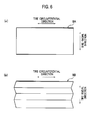
- FIG. 6 are perspective views showing only inside and outside circumferential sipes provided on inside and outside block of a pneumatic tire of a modified example 1.
- FIG. 7 are perspective views showing only inside and outside lateral sipes provided on inside and outside block of a pneumatic tire of a modified example 2.
- the pneumatic tire 1 according to the present embodiment is a commonly-used radial tire (winter tire) including beads, a carcass layer(s) and a belt layer(s) [not shown]. And the pneumatic tire 1 according to the present embodiment is equipped onto a passenger car.
- a tread of the pneumatic tire 1 has blocks 7 segmented by plural circumferential grooves 3 extending along a tire circumferential direction and plural lateral grooves 5 extending along a tread width direction.
- Circumferential sipes 9 extending along the tire circumferential direction and lateral sipes 11 extending along the tread width direction are formed in the blocks 7 .
- the circumferential sipes 9 are composed of inside circumferential sipes 9 A located inside IN a tire equatorial plane CL under being equipped onto a vehicle and outside circumferential sipes 9 B located outside OUT.
- the inside circumferential sipes 9 A are provided in the blocks 7 located inside IN the tire equatorial plane CL under being equipped onto a vehicle (hereinafter, referred as the inside blocks).
- the outside circumferential sipes 9 B are provided in the blocks 7 located outside OUT the tire equatorial plane CL under being equipped onto a vehicle (hereinafter, referred as the outside blocks).
- the lateral sipes 11 are composed of inside lateral sipes 11 A located inside IN the tire equatorial plane CL under being equipped onto a vehicle and outside lateral sipes 11 B located outside OUT.
- the inside lateral sipes 11 A are provided on the inside blocks 7 .
- the outside lateral sipes 11 B are provided on the outside blocks 7 .
- the inside circumferential sipes 9 A extend along the tire circumferential direction in repeated zigzag patterns.
- the inside circumferential sipes 9 A extend straight along the tire radial direction.
- the inside lateral sipes 11 A extend along the tread width direction in repeated zigzag patterns.
- the inside lateral sipes 11 A extend along the tire radial direction in repeated zigzag patterns.
- the inside lateral sipes 11 A are not limited to lateral sipes extending in repeated zigzag patterns three times in the tire radial direction and may be obviously lateral sipes extending in repeated zigzag patterns two times in the tire radial direction as shown in FIG. 3( b ).
- the outside circumferential sipes 9 B extend along the tire circumferential direction in repeated zigzag patterns.
- the outside circumferential sipes 9 B extend along the tire radial direction in repeated zigzag patterns.
- the outside circumferential sipes 9 B are not limited to circumferential sipes extending with repeated bends three times in the tire radial direction and may be obviously circumferential sipes extending with repeated bends two times in the tire radial direction as shown in FIG. 4( b ).
- the outside lateral sipes 11 B extend along the tread width direction in zigzag patterns.
- the outside lateral sipes 11 B extend straight along the tire radial direction.
- the number of circumferential bends of each circumferential ripe 9 on the tread is made fewer than the number of lateral bends of each lateral sipe 11 in order to restrain stiffness reduction of the blocks 7 (the inside and outside blocks).
- a depth D 1 of each inside circumferential sipe 9 A is made almost equal to a depth D 2 of each outside circumferential sipe 9 B in order to ensure absorbability and drainability of water, snow or the like at a contact plane (between the tread and a road surface). Furthermore, it is preferable that a depth D 3 of each inside lateral sipe 11 A is made almost equal to a depth D 4 of each outside lateral sipe 11 B.
- the circumferential sipes 9 (the inside circumferential sipes 9 A and the outside circumferential sipes 9 B) in the above-described embodiment extend along the tire circumferential direction in zigzag patterns. However, the circumferential sipes can be modified as described below. Note that different points from the pneumatic tire 1 in the above-described embodiment will be mainly explained hereinafter.
- the inside circumferential sipes 9 A extend straight along the tire circumferential direction. Also in this case, the inside circumferential sipes 9 A extend straight along the tire radial direction.
- the outside circumferential sipes 9 B extend straight along the tire circumferential direction. Also in this case, the outside circumferential sipes 9 B extend along the tire radial direction in zigzag patterns.
- the lateral sipes 11 (the inside lateral sipes 11 A and the outside lateral sipes 11 B) in the above-described embodiment extend along the tire width direction in zigzag patterns.
- the lateral sipes can be modified as described below.
- the inside lateral sipes 11 A extend straight along the tread width direction. Also in this case, the inside lateral sipes 11 A extend along the tire radial direction in zigzag patterns.
- the outside lateral sipes 11 B extend straight along the tread width direction. Also in this case, the outside lateral sipes 11 B extend straight along the tire radial direction.
- all the inside lateral sipes 11 A extend along the tire radial direction in zigzag patterns.
- the inside lateral sipes are not limited to this configuration. At least some of the inside lateral sipes 11 A may extend along the tire radial direction in zigzag patterns.
- only the inside lateral sipes 11 A in the blocks 7 located in tread shoulder areas S may extend along the tire radial direction in zigzag patterns.
- only the inside lateral sipes 11 A in the blocks 7 located in tread middle areas M between a tread center area C and the tread shoulder areas S may extend along the tire radial direction in zigzag patterns.
- all the outside circumferential sipes 9 B extend along the tire radial direction in zigzag patterns.
- the outside circumferential sipes are not limited to this configuration. At least some of the outside circumferential sipes 9 B may extend along the tire radial direction in zigzag patterns.
- only the outside circumferential sipes 9 B in the blocks 7 located in the tread shoulder areas S may extend along the tire radial direction in zigzag patterns.
- only the outside circumferential sipes 9 B in the blocks 7 located in the tread middle areas M may extend along the tire radial direction in zigzag patterns.
- the pneumatic tire 1 according to the above-described embodiment is a common-used radial tire including beads, a carcass layer(s) and a belt layer(s) [not shown].
- the pneumatic tire according to the present invention is not limited to this and may be a tire other than a radial tire (for example, a bias tire).
- the pneumatic tire 1 according to the above-described embodiment is equipped onto a passenger car.
- the pneumatic tire according to the present invention is not limited to this and may be equipped onto a vehicle other than a passenger car (for example, a bus or a truck).
- the circumferential sipes 9 (the inside circumferential sipes 9 A and the outside circumferential sipes 9 B) are provided on each of the blocks 7 one by one.
- the circumferential sipes are not limited to this configuration and may be provided on each of the blocks 7 in a plurality (for example, two).
- stiffness reduction of the inside and outside blocks can be restrained, and thereby a handling performance, especially, a startup accelerating performance, a braking performance and a cornering performance can be improved.
- the inside circumferential sipes 9 A extend straight along the tire radial direction and the inside lateral sipes 11 A extend along the tire radial direction in repeated zigzag patterns, zigzags along the tire radial direction in the inside lateral sipes 11 A are supported each other (so as to be engaged each other) to increase strength against loads at starting and braking and thereby stiffness reduction of the inside blocks can be restrained.
- outside circumferential sipes 9 B extend along the tire radial direction in repeated zigzag patterns and the outside lateral sipes 11 B extend straight along the tire radial direction, zigzags along the tire radial direction in the outside circumferential sipes 9 B are supported each other (so as to be engaged each other) to increase strength against lateral forces while cornering and thereby stiffness reduction of the outside blocks can be restrained.
- a handling performance especially, a startup accelerating performance, a braking performance and a cornering performance can be improved regardless of road surface conditions such as dry roads, wet roads or snow/ice covered roads.
- inside circumferential sipes 9 A and the outside circumferential sipes 9 B extend along the tire circumferential direction in repeated zigzag patterns, strength against lateral forces while cornering can be made increased to increase the edge effect and thereby a cornering performance can be further improved.
- inside lateral sipes 11 A and the outside lateral sipes 11 B extend along the tread width direction in repeated zigzag patterns, strength against loads at starting and braking can be made increased to increase the edge effect and thereby a startup accelerating performance and a braking performance can be further improved.
- Sipe patterns of the pneumatic tires of the embodiment and the comparative samples 1 and 2 are shown in upper areas on Table 1.
- the inside circumferential sipes and the outside lateral sipes extend straight along the tire radial direction and the inside lateral sipes and the outside circumferential sipes extend along the tire radial direction in zigzag patterns.
- the inside circumferential sipes, the inside lateral sipes, the outside circumferential sipes and the outside lateral sipes extend straight along the tire radial direction.
- the inside circumferential sipes, the inside lateral sipes, the outside circumferential sipes and the outside lateral sipes extend along the tire radial direction in zigzag patterns.
- a cornering performance, a braking performance and a startup accelerating performance are shown in lower areas on Table 1.
- acceleration time is time from speed 0 km/h to 20 km/h (acceleration time) on snow covered and ice covered test courses with a vehicle equipped with the pneumatic tires according to the comparative sample 1. Based on this condition, acceleration times of vehicles equipped with the pneumatic tires according to the embodiment and the comparative sample 2 were measured and their relative values were calculated. Note that the shorter acceleration time is, the better a startup accelerating performance is.
- the inside circumferential sipes extend straight along the tire radial direction and the outside circumferential sipes extend along the tire radial direction in zigzag patterns, stiffness reduction of the outside blocks can be restrained and thereby a handling performance, especially, a startup accelerating performance, a braking performance and a cornering performance can be improved.
Landscapes
- Engineering & Computer Science (AREA)
- Mechanical Engineering (AREA)
- Tires In General (AREA)
- Pharmaceuticals Containing Other Organic And Inorganic Compounds (AREA)
- Acyclic And Carbocyclic Compounds In Medicinal Compositions (AREA)
- Transition And Organic Metals Composition Catalysts For Addition Polymerization (AREA)
- Medicines Containing Material From Animals Or Micro-Organisms (AREA)
Applications Claiming Priority (5)
| Application Number | Priority Date | Filing Date | Title |
|---|---|---|---|
| JP2006042855 | 2006-02-20 | ||
| JP2006-042857 | 2006-02-20 | ||
| JP2006042857 | 2006-02-20 | ||
| JP2006-042855 | 2006-02-20 | ||
| PCT/JP2007/053054 WO2007097309A1 (ja) | 2006-02-20 | 2007-02-20 | 空気入りタイヤ |
Publications (2)
| Publication Number | Publication Date |
|---|---|
| US20100224297A1 US20100224297A1 (en) | 2010-09-09 |
| US8210221B2 true US8210221B2 (en) | 2012-07-03 |
Family
ID=38437349
Family Applications (1)
| Application Number | Title | Priority Date | Filing Date |
|---|---|---|---|
| US12/279,961 Active 2029-05-31 US8210221B2 (en) | 2006-02-20 | 2007-02-20 | Pneumatic tire with tread having inside and outside circumferential sipes |
Country Status (9)
| Country | Link |
|---|---|
| US (1) | US8210221B2 (de) |
| EP (1) | EP1987964B1 (de) |
| JP (1) | JP4769858B2 (de) |
| KR (1) | KR20080095884A (de) |
| CN (1) | CN101384441B (de) |
| AT (1) | ATE497888T1 (de) |
| DE (1) | DE602007012415D1 (de) |
| RU (1) | RU2381109C1 (de) |
| WO (1) | WO2007097309A1 (de) |
Families Citing this family (35)
| Publication number | Priority date | Publication date | Assignee | Title |
|---|---|---|---|---|
| JP4316603B2 (ja) * | 2006-11-27 | 2009-08-19 | 東洋ゴム工業株式会社 | 空気入りタイヤ |
| JP2010023586A (ja) * | 2008-07-16 | 2010-02-04 | Bridgestone Corp | 空気入りタイヤ |
| JP5559878B2 (ja) * | 2009-06-29 | 2014-07-23 | ミシュラン ルシェルシュ エ テクニーク ソシエテ アノニム | タイヤの雪上静止摩擦、ハイウェイ磨耗、およびオフロード性能の改善のための、方法ならびに構成 |
| FR2956355B1 (fr) * | 2010-02-12 | 2012-05-18 | Michelin Soc Tech | Pneumatique pour vehicules a deux roues comportant une bande de roulement presentant des incisions. |
| FR2956354A1 (fr) * | 2010-02-12 | 2011-08-19 | Michelin Soc Tech | Pneumatique pour vehicules a deux roues comportant une bande de roulement presentant des incisions. |
| JP5250063B2 (ja) * | 2011-02-28 | 2013-07-31 | 住友ゴム工業株式会社 | 空気入りタイヤ |
| JP5790166B2 (ja) * | 2011-06-02 | 2015-10-07 | 横浜ゴム株式会社 | 空気入りタイヤ |
| CN103826873B (zh) * | 2011-09-28 | 2016-08-17 | 株式会社普利司通 | 充气轮胎 |
| US9463670B2 (en) * | 2011-10-04 | 2016-10-11 | The Yokohama Rubber Co., Ltd. | Pneumatic tire |
| CN103182906B (zh) * | 2011-12-28 | 2015-12-02 | 建大橡胶(中国)有限公司 | 雪地用轮胎 |
| JP5454602B2 (ja) * | 2012-03-14 | 2014-03-26 | 横浜ゴム株式会社 | 空気入りタイヤ |
| JP5948995B2 (ja) * | 2012-03-14 | 2016-07-06 | 横浜ゴム株式会社 | 空気入りタイヤ |
| JP5629286B2 (ja) * | 2012-05-15 | 2014-11-19 | 住友ゴム工業株式会社 | 空気入りタイヤ |
| JP6019780B2 (ja) * | 2012-06-08 | 2016-11-02 | 横浜ゴム株式会社 | 空気入りタイヤ |
| ITTO20120871A1 (it) * | 2012-10-05 | 2014-04-06 | Bridgestone Corp | Striscia di battistrada per un pneumatico invernale provvista di intagli tridimensionali |
| JP5942795B2 (ja) * | 2012-11-07 | 2016-06-29 | 横浜ゴム株式会社 | 空気入りタイヤ |
| JP6287554B2 (ja) * | 2014-04-30 | 2018-03-07 | 横浜ゴム株式会社 | 空気入りタイヤ |
| NL2009980C2 (en) * | 2012-12-13 | 2014-06-16 | Ct Voor Tech Informatica B V | A method of producing glass products from glass product material and an assembly for performing said method. |
| JP5870047B2 (ja) * | 2013-01-08 | 2016-02-24 | 住友ゴム工業株式会社 | 空気入りタイヤ |
| RU2667710C2 (ru) * | 2013-02-28 | 2018-09-24 | Пирелли Тайр С.П.А. | Зимняя шина |
| CN104228469A (zh) * | 2013-06-24 | 2014-12-24 | 建大橡胶(中国)有限公司 | 雪地轮胎 |
| WO2015100079A1 (en) * | 2013-12-24 | 2015-07-02 | Bridgestone Americas Tire Operations, Llc | Tire with grooves having variable depth |
| CN106103140A (zh) * | 2014-03-07 | 2016-11-09 | 普利司通美国轮胎运营有限责任公司 | 以刀槽花纹为特色的轮胎胎面 |
| JP5920532B2 (ja) * | 2014-05-01 | 2016-05-18 | 横浜ゴム株式会社 | 空気入りタイヤ |
| JP6329010B2 (ja) * | 2014-06-13 | 2018-05-23 | 株式会社ブリヂストン | 空気入りタイヤ |
| US10603961B2 (en) | 2014-10-07 | 2020-03-31 | The Yokohama Rubber Co., Ltd. | Pneumatic tire |
| JP6374826B2 (ja) * | 2015-04-09 | 2018-08-15 | 住友ゴム工業株式会社 | 空気入りタイヤ |
| RU2689645C1 (ru) * | 2015-11-12 | 2019-05-28 | Бриджстоун Корпорейшн | Шина |
| JP6929613B2 (ja) * | 2015-11-12 | 2021-09-01 | 株式会社ブリヂストン | タイヤ |
| JP6627554B2 (ja) * | 2016-02-15 | 2020-01-08 | 住友ゴム工業株式会社 | 空気入りタイヤ |
| JP6790495B2 (ja) * | 2016-06-24 | 2020-11-25 | 住友ゴム工業株式会社 | タイヤ |
| JP6822195B2 (ja) * | 2017-02-15 | 2021-01-27 | 横浜ゴム株式会社 | 空気入りタイヤ |
| JP6562130B2 (ja) * | 2018-07-19 | 2019-08-21 | 住友ゴム工業株式会社 | 空気入りタイヤ |
| JP7183747B2 (ja) * | 2018-12-03 | 2022-12-06 | 住友ゴム工業株式会社 | タイヤ |
| RU2751726C1 (ru) * | 2021-01-13 | 2021-07-16 | Публичное акционерное общество "Нижнекамскшина" | Протектор шины и пластинка для закрепления в вулканизационной форме для образования 3D щелевидной прорези в блоке протектора шины |
Citations (17)
| Publication number | Priority date | Publication date | Assignee | Title |
|---|---|---|---|---|
| JPH02267006A (ja) | 1989-04-07 | 1990-10-31 | Bridgestone Corp | 空気入りタイヤ |
| JPH06127217A (ja) * | 1992-10-13 | 1994-05-10 | Bridgestone Corp | 空気入りタイヤ |
| JPH08244417A (ja) | 1995-03-10 | 1996-09-24 | Bridgestone Corp | 重荷重用スタッドレス空気入りタイヤ |
| EP0952011A2 (de) | 1998-04-22 | 1999-10-27 | Bridgestone Corporation | Luftreifen |
| JP2000006619A (ja) | 1998-04-22 | 2000-01-11 | Bridgestone Corp | 空気入りタイヤ |
| JP2000190711A (ja) | 1998-12-23 | 2000-07-11 | Pirelli Pneumatici Spa | 車の車輪用タイヤ及び車の車輪用タイヤのトレッドパターン内に雪の取り込みを増す方法 |
| JP2002187412A (ja) * | 2000-12-20 | 2002-07-02 | Toyo Tire & Rubber Co Ltd | 空気入りタイヤ |
| JP2002254906A (ja) | 2001-03-01 | 2002-09-11 | Toyo Tire & Rubber Co Ltd | 空気入りラジアルタイヤ |
| US20020139164A1 (en) * | 2001-03-27 | 2002-10-03 | Ngk Insulators, Ltd. | Press die for molding sipe blade and method of making the press die |
| DE10214913A1 (de) | 2001-04-05 | 2002-10-10 | Yokohama Rubber Co Ltd | Pneumatischer Reifen |
| EP1277599A2 (de) | 2001-07-18 | 2003-01-22 | Sumitomo Rubber Industries Ltd. | Luftreifen |
| JP2004026158A (ja) | 2003-10-20 | 2004-01-29 | Bridgestone Corp | 重荷重用スタッドレス空気入りタイヤ |
| DE10360432A1 (de) | 2002-12-24 | 2004-07-08 | Sumitomo Rubber Industries Ltd., Kobe | Luftreifen und Herstellungsverfahren dafür |
| WO2005030502A1 (ja) | 2003-09-29 | 2005-04-07 | The Yokohama Rubber Co., Ltd. | 空気入りタイヤ |
| JP2005126055A (ja) | 2003-09-29 | 2005-05-19 | Yokohama Rubber Co Ltd:The | 空気入りタイヤ |
| JP2005162058A (ja) | 2003-12-03 | 2005-06-23 | Sumitomo Rubber Ind Ltd | 空気入りタイヤ |
| JP2007045316A (ja) * | 2005-08-10 | 2007-02-22 | Toyo Tire & Rubber Co Ltd | 空気入りタイヤ |
Family Cites Families (1)
| Publication number | Priority date | Publication date | Assignee | Title |
|---|---|---|---|---|
| JP4138688B2 (ja) * | 2004-03-25 | 2008-08-27 | 住友ゴム工業株式会社 | 空気入りタイヤ |
-
2007
- 2007-02-20 DE DE602007012415T patent/DE602007012415D1/de active Active
- 2007-02-20 AT AT07714557T patent/ATE497888T1/de not_active IP Right Cessation
- 2007-02-20 KR KR1020087020339A patent/KR20080095884A/ko not_active Application Discontinuation
- 2007-02-20 JP JP2008501717A patent/JP4769858B2/ja active Active
- 2007-02-20 US US12/279,961 patent/US8210221B2/en active Active
- 2007-02-20 WO PCT/JP2007/053054 patent/WO2007097309A1/ja active Application Filing
- 2007-02-20 CN CN2007800060528A patent/CN101384441B/zh active Active
- 2007-02-20 EP EP07714557A patent/EP1987964B1/de active Active
- 2007-02-20 RU RU2008137630/11A patent/RU2381109C1/ru active
Patent Citations (20)
| Publication number | Priority date | Publication date | Assignee | Title |
|---|---|---|---|---|
| JPH02267006A (ja) | 1989-04-07 | 1990-10-31 | Bridgestone Corp | 空気入りタイヤ |
| JPH06127217A (ja) * | 1992-10-13 | 1994-05-10 | Bridgestone Corp | 空気入りタイヤ |
| JPH08244417A (ja) | 1995-03-10 | 1996-09-24 | Bridgestone Corp | 重荷重用スタッドレス空気入りタイヤ |
| EP0952011A2 (de) | 1998-04-22 | 1999-10-27 | Bridgestone Corporation | Luftreifen |
| JP2000006619A (ja) | 1998-04-22 | 2000-01-11 | Bridgestone Corp | 空気入りタイヤ |
| JP2000190711A (ja) | 1998-12-23 | 2000-07-11 | Pirelli Pneumatici Spa | 車の車輪用タイヤ及び車の車輪用タイヤのトレッドパターン内に雪の取り込みを増す方法 |
| JP2002187412A (ja) * | 2000-12-20 | 2002-07-02 | Toyo Tire & Rubber Co Ltd | 空気入りタイヤ |
| JP2002254906A (ja) | 2001-03-01 | 2002-09-11 | Toyo Tire & Rubber Co Ltd | 空気入りラジアルタイヤ |
| US20020139164A1 (en) * | 2001-03-27 | 2002-10-03 | Ngk Insulators, Ltd. | Press die for molding sipe blade and method of making the press die |
| DE10214913A1 (de) | 2001-04-05 | 2002-10-10 | Yokohama Rubber Co Ltd | Pneumatischer Reifen |
| EP1277599A2 (de) | 2001-07-18 | 2003-01-22 | Sumitomo Rubber Industries Ltd. | Luftreifen |
| JP2003025812A (ja) | 2001-07-18 | 2003-01-29 | Sumitomo Rubber Ind Ltd | 空気入りタイヤ及びその加硫金型 |
| DE10360432A1 (de) | 2002-12-24 | 2004-07-08 | Sumitomo Rubber Industries Ltd., Kobe | Luftreifen und Herstellungsverfahren dafür |
| US20040134579A1 (en) | 2002-12-24 | 2004-07-15 | Susuma Tanaka | Pneumatic tire and producing method thereof |
| WO2005030502A1 (ja) | 2003-09-29 | 2005-04-07 | The Yokohama Rubber Co., Ltd. | 空気入りタイヤ |
| JP2005126055A (ja) | 2003-09-29 | 2005-05-19 | Yokohama Rubber Co Ltd:The | 空気入りタイヤ |
| JP2004026158A (ja) | 2003-10-20 | 2004-01-29 | Bridgestone Corp | 重荷重用スタッドレス空気入りタイヤ |
| JP2005162058A (ja) | 2003-12-03 | 2005-06-23 | Sumitomo Rubber Ind Ltd | 空気入りタイヤ |
| EP1552967A2 (de) | 2003-12-03 | 2005-07-13 | Sumitomo Rubber Industries Limited | Luftreifen |
| JP2007045316A (ja) * | 2005-08-10 | 2007-02-22 | Toyo Tire & Rubber Co Ltd | 空気入りタイヤ |
Non-Patent Citations (4)
| Title |
|---|
| Machine translation for Japan 06-127217 (no date). * |
| Machine translation for Japan 2002-187412 (no date). * |
| Machine translation for Japan 2007-045316 (no date). * |
| Supplementary European Search Report dated Sep. 23, 2009. |
Also Published As
| Publication number | Publication date |
|---|---|
| WO2007097309A1 (ja) | 2007-08-30 |
| CN101384441B (zh) | 2010-12-01 |
| ATE497888T1 (de) | 2011-02-15 |
| RU2381109C1 (ru) | 2010-02-10 |
| US20100224297A1 (en) | 2010-09-09 |
| DE602007012415D1 (de) | 2011-03-24 |
| CN101384441A (zh) | 2009-03-11 |
| EP1987964A4 (de) | 2009-10-21 |
| EP1987964A1 (de) | 2008-11-05 |
| EP1987964B1 (de) | 2011-02-09 |
| KR20080095884A (ko) | 2008-10-29 |
| JPWO2007097309A1 (ja) | 2009-07-16 |
| JP4769858B2 (ja) | 2011-09-07 |
Similar Documents
| Publication | Publication Date | Title |
|---|---|---|
| US8210221B2 (en) | Pneumatic tire with tread having inside and outside circumferential sipes | |
| US10752057B2 (en) | Pneumatic tire | |
| US9085201B2 (en) | Pneumatic tire | |
| US8640750B2 (en) | Pneumatic tire with tread having shoulder blocks and crown blocks | |
| US7832439B2 (en) | Pneumatic tire having recess in buttress face | |
| US10099441B2 (en) | Tire vulcanization mold and method for manufacturing tire | |
| US20100006198A1 (en) | Pneumatic tire | |
| US20120132334A1 (en) | Pneumatic tire | |
| US20110041973A1 (en) | Pneumatic tire | |
| JP4786317B2 (ja) | 空気入りラジアルタイヤ | |
| US8636043B2 (en) | Pneumatic tire | |
| EA018005B1 (ru) | Протектор шины с направленным рисунком | |
| EP0588623A1 (de) | Radialer Reifen | |
| JP4778866B2 (ja) | 空気入りタイヤ | |
| EP3517322A1 (de) | Reifen | |
| US8844590B2 (en) | Tire with tread having projecting portion projecting from groove bottom of circumferential groove | |
| CN111511586A (zh) | 可镶钉轮胎及充气轮胎 | |
| US20220161605A1 (en) | Tire | |
| US20230031908A1 (en) | Tire | |
| JP4656989B2 (ja) | 空気入りタイヤ | |
| CN111094018B (zh) | 充气轮胎 | |
| RU2733310C2 (ru) | Шина | |
| JP3548302B2 (ja) | スタッドレス空気入りタイヤ | |
| CN114845889B (zh) | 轮胎 | |
| RU2791336C1 (ru) | Шина |
Legal Events
| Date | Code | Title | Description |
|---|---|---|---|
| AS | Assignment |
Owner name: BRIDGESTONE CORPORATION, JAPAN Free format text: ASSIGNMENT OF ASSIGNORS INTEREST;ASSIGNORS:KIWAKI, YUKIHIRO;WATABE, RYOICHI;SIGNING DATES FROM 20081210 TO 20081211;REEL/FRAME:022019/0889 |
|
| STCF | Information on status: patent grant |
Free format text: PATENTED CASE |
|
| FEPP | Fee payment procedure |
Free format text: PAYOR NUMBER ASSIGNED (ORIGINAL EVENT CODE: ASPN); ENTITY STATUS OF PATENT OWNER: LARGE ENTITY |
|
| FPAY | Fee payment |
Year of fee payment: 4 |
|
| MAFP | Maintenance fee payment |
Free format text: PAYMENT OF MAINTENANCE FEE, 8TH YEAR, LARGE ENTITY (ORIGINAL EVENT CODE: M1552); ENTITY STATUS OF PATENT OWNER: LARGE ENTITY Year of fee payment: 8 |
|
| MAFP | Maintenance fee payment |
Free format text: PAYMENT OF MAINTENANCE FEE, 12TH YEAR, LARGE ENTITY (ORIGINAL EVENT CODE: M1553); ENTITY STATUS OF PATENT OWNER: LARGE ENTITY Year of fee payment: 12 |