US8040089B2 - Drive device for synchronous electric motor - Google Patents
Drive device for synchronous electric motor Download PDFInfo
- Publication number
- US8040089B2 US8040089B2 US12/385,632 US38563209A US8040089B2 US 8040089 B2 US8040089 B2 US 8040089B2 US 38563209 A US38563209 A US 38563209A US 8040089 B2 US8040089 B2 US 8040089B2
- Authority
- US
- United States
- Prior art keywords
- modulation scheme
- phase
- drive device
- switching elements
- phase command
- Prior art date
- Legal status (The legal status is an assumption and is not a legal conclusion. Google has not performed a legal analysis and makes no representation as to the accuracy of the status listed.)
- Expired - Fee Related, expires
Links
Images


Classifications
-
- H—ELECTRICITY
- H02—GENERATION; CONVERSION OR DISTRIBUTION OF ELECTRIC POWER
- H02P—CONTROL OR REGULATION OF ELECTRIC MOTORS, ELECTRIC GENERATORS OR DYNAMO-ELECTRIC CONVERTERS; CONTROLLING TRANSFORMERS, REACTORS OR CHOKE COILS
- H02P6/00—Arrangements for controlling synchronous motors or other dynamo-electric motors using electronic commutation dependent on the rotor position; Electronic commutators therefor
- H02P6/14—Electronic commutators
-
- H—ELECTRICITY
- H02—GENERATION; CONVERSION OR DISTRIBUTION OF ELECTRIC POWER
- H02P—CONTROL OR REGULATION OF ELECTRIC MOTORS, ELECTRIC GENERATORS OR DYNAMO-ELECTRIC CONVERTERS; CONTROLLING TRANSFORMERS, REACTORS OR CHOKE COILS
- H02P6/00—Arrangements for controlling synchronous motors or other dynamo-electric motors using electronic commutation dependent on the rotor position; Electronic commutators therefor
- H02P6/20—Arrangements for starting
- H02P6/21—Open loop start
Definitions
- the present invention relates to a drive device for a synchronous electric motor, in which windings of a stator coil are connected together to form a star connection.
- Japanese Patent 3223842 (corresponding to U.S. Pat. No. 6,320,775) discloses a drive device, which includes an inverter circuit and a control circuit.
- the inverter circuit includes six transistors (i.e., three upper arm transistors located adjacent to a cathode bus bar and three lower arm transistors located adjacent to an anode bus bar) and six diodes (i.e., three upper arm diodes located adjacent to the cathode bus bar and three lower arm diodes located adjacent to the anode bus bar).
- the control circuit controls the inverter circuit.
- a direct current (DC) power supply device is connected between a neutral point of the stator coil and the anode bus bar.
- a capacitor is connected between the anode bus bar the cathode bus bar.
- the control circuit executes a switching operation of the six transistors, so that three-phase alternate currents are supplied to a three-phase alternate current synchronous electric motor (hereinafter, simply referred to as a three-phase AC synchronous motor) in response to a voltage difference between the cathode bus bar and the anode bus bar.
- a three-phase AC synchronous motor hereinafter, simply referred to as a three-phase AC synchronous motor
- a drive device for a synchronous electric motor that includes a stator coil having a plurality of windings, which are connected together to form a star connection and generate a rotating magnetic field upon energization thereof with electric current supplied from a power supply device to rotate a rotor of the synchronous electric motor.
- the drive device includes an inverter circuit, a capacitor, a control means, a power supply state sensing means and a deciding means.
- the inverter circuit includes a plurality of arm pairs, which are connected in parallel between a cathode bus bar and an anode bus bar.
- Each of the plurality of arm pairs is adapted to connect with a corresponding one of the plurality of windings and includes an upper arm and a lower arm, which are connected in series between the cathode bus bar and the anode bus bar and have an upper arm switching element and a lower arm switching element, respectively.
- the capacitor is connected to the inverter circuit.
- the control means is for executing a switching operation of the upper arm switching elements and the lower arm switching elements of the plurality of arm pairs by obtaining and supplying a control signal to each corresponding one of the upper arm switching elements and the lower arm switching elements of the plurality of arm pairs through use of a selected modulation scheme that is selected from a plurality of modulation schemes, each of which is set to charge the capacitor with a corresponding charge amount that differs from that of any other one of the plurality of modulation schemes, so that the rotating magnetic flied is generated at the stator coil according to an output state of the capacitor and an output state of the power supply device.
- the capacitor is charged with the electric current, which flows from the stator coil to the capacitor while bypassing each corresponding one of the upper arm switching elements and the lower arm switching elements of the plurality of arm pairs upon the execution of the switching operation of the upper arm switching elements and the lower arm switching elements of the plurality of arm pairs by the control means.
- the power supply state sensing means is for sensing the output state of the power supply device.
- the deciding means is for deciding which one of the plurality of the modulation schemes is used as the selected modulation scheme based on a sensed value of the power supply state sensing means.
- the charge amount of the capacitor is adjusted according to the output state of the power supply device upon the execution of the switching operation of the upper arm switching elements and the lower arm switching elements of the plurality of arm pairs by the control means according to the control signal obtained with the selected modulation scheme.
- FIG. 1 is a diagram showing a drive device for a three-phase AC synchronous electric motor according to a first embodiment of the present invention
- FIG. 2 is a diagram showing a three-phase modulation scheme according to the first embodiment
- FIG. 3 is a diagram showing a two-phase modulation scheme according to the first embodiment
- FIG. 4 is a diagram showing another two-phase modulation scheme according to the first embodiment
- FIG. 5 is a flowchart showing a control operation of a control circuit shown in FIG. 1 ;
- FIG. 6 is a flowchart showing a control operation of a control circuit according to a second embodiment of the present invention.
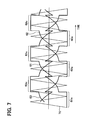
- FIG. 7 is a diagram showing a two-phase modulation scheme according to the second embodiment.
- FIG. 1 shows a three-phase AC synchronous motor according to a first embodiment of the present invention. More specifically, FIG. 1 shows a circuit structure of a drive device and a portion of the three-phase AC synchronous motor.
- the drive device 10 generates the three-phase alternate currents based on the direct current voltage and outputs the thus generated three-phase alternate currents to the three-phase AC synchronous motor to drive the same.
- a load e.g., a compressor mechanism
- a load is connected to an output shaft of the three-phase AC synchronous motor.
- the three-phase AC synchronous motor includes a rotor (not shown) and a stator coil 1 . Permanent magnets are provided to the rotor, and the stator coil 1 applies a rotating magnetic field to the rotor.
- the stator coil 1 includes three-phase windings, i.e., a U-phase winding 1 a , a V-phase winding 1 b and a W-phase winding 1 c , which form a star connection and has a neutral point 1 x at a center connection point where the windings 1 a , 1 b , 1 c are connected together.
- a power supply device (a vehicle battery in this instance) 3 is placed between the neutral point 1 x of the stator coil 1 and the ground.
- the structure of the three-phase AC synchronous motor does not allow installation of a sensor, which senses a rotational position (positional information) of the rotor, into the three-phase AC synchronous motor.
- the drive device 10 includes an inverter circuit 20 , a capacitor 30 , a current sensor 40 , a voltage sensor (serving as a power supply state sensing means) 45 and a control circuit 50 .
- the inverter circuit 20 generates the three-phase alternate currents based on an output voltage of the power supply device 3 and a voltage difference between a positive electrode and a negative electrode of the capacitor 30 and outputs the thus generated three-phase alternate currents to the stator coil 1 .
- the inverter circuit 20 includes a plurality of switching elements (three upper arm switching elements and three lower arm switching elements in this instance) SW 1 -SW 6 and a plurality of diodes (three upper arm diodes and three lower arm diodes in this instance) D 1 -D 6 . More specifically, the inverter circuit 20 includes a plurality of arm pairs, which are connected in parallel between a cathode bus bar 22 and an anode bus bar 21 .
- Each of the arm pairs is adapted to connect with a corresponding one of the windings 1 a , 1 b , 1 c and includes an upper arm AM 1 -AM 3 and a lower arm AM 4 -AM 6 , which are connected in series between the cathode bus bar 22 and the anode bus bar 21 .
- each upper arm AM 1 -AM 3 is provided with the corresponding upper arm switching element (also referred to as a cathode bus bar 22 side switching element) SW 1 -SW 3 and the corresponding upper arm diode D 1 -D 3
- each lower arm AM 4 -AM 6 is provided with the corresponding lower arm switching element (also referred to as an anode bus bar 21 side switching element) SW 4 -SW 6 and the corresponding lower arm diode D 4 -D 6 .
- the switching elements SW 1 , SW 4 of the first arm pair (i.e., the upper and lower arms AM 1 , AM 4 ) are connected in series between the anode bus bar 21 and the cathode bus bar 22 .
- the switching elements SW 2 , SW 5 of the second arm pair (i.e., the upper and lower arms AM 2 , AM 5 ) are connected in series between the anode bus bar 21 and the cathode bus bar 22 .
- the switching elements SW 3 , SW 6 of the third arm pair (i.e., the upper and lower arms AM 3 , AM 6 ) are connected in series between the anode bus bar 21 and the cathode bus bar 22 .
- the anode bus bar 21 is connected to the ground.
- a common connection T 3 between the switching element SW 3 and the switching element SW 6 i.e., between the upper arm AM 3 and the lower arm AM 6 is connected to the U-phase winding 1 a.
- the switching elements SW 1 -SW 6 may be semiconductor switching elements, such as insulated gate bipolar transistors, field-effect transistors or the like.
- Each of the diodes D 1 -D 6 is connected to a corresponding one of the switching elements SW 1 -SW 6 to form an anti-parallel connection therewith.
- the capacitor 30 cooperates with the power supply device 3 to apply an output voltage to the inverter circuit 20 .
- the positive electrode of the capacitor 30 is connected to the cathode bus bar 22 of the inverter circuit 20 .
- the negative electrode of the capacitor 30 is connected to the neutral point 1 x of the stator coil 1 .
- the current sensor 40 senses each of an U-phase current iu, a V-phase current iv and a W-phase current iw.
- the U-phase current iu is the current, which flows from the common connection T 3 between the switching element SW 3 and the switching element SW 6 to the U-phase winding 1 a .
- the V-phase current iv is the current, which flows from the common connection T 2 between the switching element SW 2 and the switching element SW 5 to the V-phase winding 1 b .
- the W-phase current iw is the current, which flows from the common connection T 1 between the switching element SW 1 and the switching element SW 4 to the W-phase winding 1 c.
- a direction which is indicated by an arrow of each of the U-, V- and W-phase currents iu, iv, iw, is a positive side.
- the voltage sensor 45 senses the output voltage VB of the power supply device 3 .
- the control circuit 50 includes a microcomputer, a memory and an analog/digital converter and controls the switching elements SW 1 -SW 6 based on the measured values of the sensors 40 , 45 and a target rotational speed received from an electronic control device 7 .
- the control circuit 50 outputs a switching signal (serving as a control signal) to the switching elements SW 1 -SW 6 .
- a switching signal serving as a control signal
- the switching elements SW 1 -SW 6 perform its corresponding switching operation.
- the three-phase alternate currents are outputted from the common connections T 1 -T 3 to the stator coil 1 .
- stator coil 1 generates the rotating magnetic field. In this way, the rotor is rotated synchronously with the rotating magnetic field.
- the switching element SW 4 when the switching element SW 4 is turned on, the electric current flows from the neutral point 1 x side to the ground through the W-phase winding 1 c and the switching element SW 4 . At this time, the magnetic energy is accumulated in the W-phase winding 1 c . Thereafter, when the switching element SW 4 is turned off, the electric current, which corresponds to the magnetic energy of the W-phase winding 1 c , flows to the cathode bus bar 22 side through the diode D 1 .
- the switching element SW 4 when the switching element SW 4 is turned off, the electric current flows from the W-phase winding 1 c to the cathode bus bar 22 side through the diode D 1 in the upper arm AM 1 while bypassing the switching element SW 1 .
- This electric current flows to the capacitor 30 as the charging current, so that the electric charge is accumulated in the capacitor 30 .
- the control circuit 50 uses a known technique of triangle-wave generated pulse width modulation (PWM) scheme.
- PWM pulse width modulation
- the timing at which the sensed current iu, iv, iw of the current sensor 40 becomes zero is obtained for each of the sensed currents iu, iv, iw. Then, the position of the rotor is estimated based on this timing. Then, the rotational speed (the number of rotations per unit time) of the rotor is estimated based on the estimated position of the rotor.
- this estimated rotational speed will be referred to as an estimated rotational speed.
- FIG. 2 shows an example of the U-phase command wave, the V-phase command wave and the W-phase command wave.
- the U-phase command wave 60 , the V-phase command wave 61 and the W-phase command wave 62 constitute the three-phase command waves.
- the U-phase command wave 60 , the V-phase command wave 61 and the W-phase command wave 62 are obtained in such a manner that a difference between the target rotational speed of the rotor and the estimated rotational speed of the rotor is minimized.
- the three-phase command waves 60 - 62 are used to determine which one of the upper arm switching element SW 1 , SW 2 , SW 3 (i.e., the switching element SW 1 , SW 2 , SW 3 placed on one side of the corresponding common connection T 1 -T 3 where the cathode bus bar 22 is located) and the lower arm switching element SW 4 , SW 5 , SW 6 (i.e., the switching element SW 4 , SW 5 , SW 6 placed on the other side of the corresponding common connection T 1 -T 3 where the anode bus bar 21 is located) needs to be turned on for each of the three phases.
- the upper arm switching element SW 1 , SW 2 , SW 3 i.e., the switching element SW 1 , SW 2 , SW 3 placed on one side of the corresponding common connection T 1 -T 3 where the cathode bus bar 22 is located
- the lower arm switching element SW 4 , SW 5 , SW 6 i.e., the switching element SW 4 , SW 5 , SW 6
- the U-phase command wave 60 corresponds to the switching elements SW 3 , SW 6 .
- a triangle wave (a carrier wave) 70 When the U-phase command wave 60 is larger than a triangle wave (a carrier wave) 70 , the upper arm switching element SW 3 is turned on, and the lower arm switching element SW 6 is turned off.
- the switching element SW 3 When the U-phase command wave 60 is smaller than the triangle wave 70 , the switching element SW 3 is turned off, and the switching element SW 6 is turned on.
- the V-phase command wave 61 corresponds to the switching elements SW 2 , SW 5 .
- the V-phase command wave 61 is larger than the triangle wave 70 , the upper arm switching element SW 2 is turned on, and the lower arm switching element SW 5 is turned off.
- the switching element SW 2 is turned off, and the switching element SW 5 is turned on.
- the W-phase command wave 62 corresponds to the switching elements SW 1 , SW 4 .
- the W-phase command wave 62 is larger than the triangle wave 70 , the upper arm switching element SW 1 is turned on, and the lower arm switching element SW 4 is turned off.
- the V-phase command wave 61 is smaller than the triangle wave 70 , the switching element SW 1 is turned off, and the switching element SW 4 is turned on.
- the switching signal which includes the thus determined information, is obtained.
- one of three modulation schemes is used.
- the three modulation schemes are set such that the three-phase command waves 60 - 62 differ from one scheme to another scheme.
- the three modulation schemes include modulation schemes A-C.
- the modulation scheme A is a first two-phase modulation scheme that makes the charging current to have a small current value.
- the modulation scheme B is a three-phase modulation scheme that makes the charging current to have an intermediate current value, which is larger than the small current value and is smaller than a large current value described below.
- the modulation scheme C is a second two-phase modulation scheme that makes the charging current to have the large current value.
- FIG. 3 shows the three-phase command waves 60 - 62 in the case of the modulation scheme A.
- a switching stop time interval 60 u during which the switching operation of the corresponding switching elements SW 3 , SW 6 for the command wave 60 is stopped, is set to be a 1 ⁇ 3 period of the command wave 60 .
- a switching stop time interval 61 u during which the switching operation of the corresponding switching elements SW 2 , SW 5 for the command wave 61 is stopped, is set to be 1 ⁇ 3 period of the command wave 61 .
- a switching stop time interval 62 u during which the switching operation of the corresponding switching elements SW 1 , SW 4 for the command wave 62 is stopped, is set to be 1 ⁇ 3 period of the command wave 62 .
- each corresponding time period, during which a corresponding one of the three-phase command waves 60 - 62 is larger than the triangle wave 70 is longer than that of the modulation scheme B (the three-phase modulation scheme).
- the corresponding upper arm switching element SW 1 , SW 2 , SW 3 is turned on, and the corresponding lower arm switching element SW 4 , SW 5 , SW 6 is turned off.
- an off-time period Toff of each of the lower arm switching elements SW 4 , SW 5 , SW 6 is shorter than that of the three-phase modulation scheme. Accordingly, in this modulation scheme, an output-to-input voltage ratio (also sometimes referred to as a set-up ratio), which is expressed by (Ton+Toff)/Toff, is smaller than that of the three-phase modulation scheme.
- the three-phase command waves 60 , 61 , 62 form sine waves, respectively, as shown in FIG. 2 .
- FIG. 4 shows the three-phase command waves 60 - 62 in the case of the modulation scheme C.
- a switching stop time interval 60 s during which the switching operation of the corresponding switching elements SW 3 , SW 6 for the command wave 60 is stopped, is set to be a 1 ⁇ 3 period of the command wave 60 .
- a switching stop time interval 61 s during which the switching operation of the corresponding switching elements SW 2 , SW 5 for the command wave 61 is stopped, is set to be 1 ⁇ 3 period of the command wave 61 .
- a switching stop time interval 62 s during which the switching operation of the corresponding switching elements SW 1 , SW 4 for the command wave 62 is stopped, is set to be 1 ⁇ 3 period of the command wave 62 .
- each corresponding time period, during which a corresponding one of the three-phase command waves 60 - 62 is larger than the triangle wave 70 is shorter than that of the modulation scheme B (three-phase modulation scheme).
- the corresponding upper arm switching element SW 1 , SW 2 , SW 3 is turned off, and the corresponding lower arm switching element SW 4 , SW 5 , SW 6 is turned on.
- an on-time period Ton of each of the lower arm switching elements SW 4 , SW 5 , SW 6 is longer than that of the modulation scheme B (the three-phase modulation scheme).
- the off-time period Toff of the above expression is the off-time period of the corresponding lower arm switching element SW 4 , SW 5 , SW 6 .
- the three types of the modulation schemes are set to have different output-to-input voltage ratios, respectively.
- the output-to-input voltage ratio is increased, the current value of the charging current is increased. Therefore, when the output-to-input voltage ratio is increased, the amount of the electric charge accumulated in the capacitor 30 is increased.
- the control circuit 50 determines which one of the three types of the modulation schemes is used based on the output voltage (hereinafter, referred to as the supply voltage) of the power supply device 3 and controls the rotational speed of the three-phase AC synchronous motor.
- FIG. 5 is a flowchart showing the motor control operation of the control circuit 50 .
- the electronic control device 7 commands the control circuit 50 to start the control operation. Then, the control circuit 50 starts execution of a corresponding computer program in consistent with the flowchart of FIG. 5 based on the command for starting the control operation from the electronic control device 7 .
- step S 100 the supply voltage, which is the output voltage of the power supply device 3 provided to the stator coil 1 and is sensed with the voltage sensor 45 , is obtained from the voltage sensor 45 .
- step S 110 it is determined whether the supply voltage is equal to or higher than a first preset value.
- the operation proceeds to step S 115 .
- the modulation scheme A is determined to be a selected modulation scheme, which is selected and is used to control the rotational speed of the three-phase AC synchronous motor.
- the modulation scheme A serves as a fourth or fifth modulation scheme of the present invention.
- step S 110 when it is determined that the supply voltage is less than the first preset value at step S 110 (i.e., NO at step S 110 ), the operation proceeds to step S 120 .
- step S 120 it is determined whether the supply voltage is less than a second preset value.
- the second preset value is a voltage value, which is lower than the first preset value.
- step S 120 When it is determined that the supply voltage is less than the second preset value at step S 120 (i.e., YES at step S 120 ), the operation proceeds to step S 125 .
- the modulation scheme C is determined to be the selected modulation scheme, which is selected and is used to control the rotational speed of the three-phase AC synchronous motor.
- the modulation scheme C serves as a second or seventh modulation scheme of the present invention.
- the modulation scheme B is determined to be the selected modulation scheme, which is selected and is used to control the rotational speed of the three-phase AC synchronous motor.
- the modulation scheme B serves as a first, third or sixth modulation scheme of the present invention.
- the modulation scheme which is selected and is used to control the rotational speed of the three-phase AC synchronous motor, is determined in the above described manner. Then, the operation proceeds to step S 140 where the switching signal is obtained by using the above-determined modulation scheme. Next, the operation proceeds to step S 150 . At step S 150 , the obtained switching signal is outputted to the switching elements SW 1 -SW 6 .
- step S 100 the supply voltage, which is sensed with the voltage sensor 45 , is obtained from the voltage sensor 45 once again. Then, the degree of the supply voltage V is identified at step 110 or step 120 , as discussed above. Thereafter, the modulation scheme, which is selected and is used to control the rotational speed of the three-phase AC synchronous motor, is determined based on the supply voltage V at the corresponding one of steps S 115 , S 125 , S 130 in the above described manner.
- step S 140 the operation proceeds to step S 140 where the corresponding switching signal is obtained by using the above-determined modulation scheme. Then, the operation proceeds to step S 150 .
- step S 150 the obtained switching signal is outputted to the switching elements SW 1 -SW 6 .
- steps S 100 -S 150 are repeated. Thereby, the three-phase alternate currents are outputted from the common connections T 1 -T 3 to the windings 1 a - 1 c of the stator coil 1 . Therefore, the rotating magnetic field, which is in consistent with the three-phase command waves 60 - 62 , is generated from the stator coil 1 . Thereby, the rotor is rotated synchronously with the rotating magnetic field.
- the modulation scheme which is used to control the rotational speed of the three-phase AC synchronous motor, is determined based on the supply voltage.
- the modulation scheme B is selected. Furthermore, in the case where the supply voltage is equal to or higher than the first preset value, the modulation scheme A, which makes the output-to-input voltage ratio to be smaller than the output-to-input voltage ratio of the modulation scheme B, is selected. In addition, in the case where the supply voltage is less than the second preset value, the modulation scheme C, which makes the output-to-input voltage ratio to be larger than the output-to-input voltage ratio of the modulation scheme B, is selected.
- control circuit 50 drives the stator coil 1 to generate the rotating magnetic field, which corresponds to the three-phase command waves 60 - 62 by using the triangle-wave generated PWM scheme. Therefore, the rotor is rotated according to the three-phase command waves 60 - 62 .
- the modulation scheme which is selected and is used to control the rotational speed of the three-phase AC synchronous motor, is determined based on the supply voltage.
- the amount of electric charge, which is accumulated in the capacitor 30 is adjusted.
- the control circuit 50 controls the rotation of the rotor of the three-phase AC synchronous motor in consistent with the three-phase command waves 60 , 61 , 62 , so that the amount of charge (the charge amount of the capacitor 30 ), which is accumulated in the capacitor 30 , is adjusted. Therefore, it is possible to adjust the charge amount of the capacitor 30 according to the output voltage of the power supply device 3 while limiting the reduction in the time period for executing the switching operation of the switching elements SW 1 -SW 6 at the time of controlling the three-phase AC synchronous motor.
- the three-phase modulation scheme is used to control the rotational speed of the AC synchronous motor.
- the rotational speed of the AC synchronous motor is controlled in the following manner.
- the control circuit of the present embodiment starts the execution of the corresponding computer program according to the flowchart shown in FIG. 6 .
- steps similar to those of FIG. 5 are indicated by the same reference numerals and will not be described again for the sake of simplicity.
- the control circuit determines to use a two-phase modulation scheme indicated in FIG. 7 as the selected modulation scheme for controlling the rotational speed of the three-phase AC synchronous motor at step S 130 A. Then, the control circuit uses this two-phase modulation scheme to obtain the switching signal (serving as the control signal) and to output this switching signal to the switching elements SW 1 -SW 6 .
- the two-phase modulation scheme indicated in FIG. 7 is a combination of the modulation scheme indicated in FIG. 3 and the modulation scheme indicated in FIG. 4 .
- the stop time interval 60 s and the stop time interval 60 u are alternately provided in the command wave 60 at the bottom side and the top side, respectively, in FIG. 7 .
- stop time interval 61 s and the stop time interval 61 u are alternately provided in the command wave 61 at the bottom side and the top side, respectively, in FIG. 7 .
- stop time interval 62 s and the stop time interval 62 u are alternately provided in the command wave 62 at the bottom side and the top side, respectively, in FIG. 7 .
- the stop time intervals are set in the respective command waves 60 - 62 in the above described manner.
- the two-phase modulation scheme shown in FIG. 7 corresponds to the first, third or sixth modulation scheme of the present invention.
- the capacitor 30 is placed between the neutral point 1 x of the stator coil 1 and the cathode bus bar 22 .
- the present invention is not limited to this.
- the capacitor 30 may be placed between the neutral point 1 x of the stator coil 1 and the anode bus bar 21 .
- the power supply device 3 may be placed between the neutral point 1 x of the stator coil 1 and the cathode bus bar 22 .
- the capacitor 30 may be placed between the cathode bus bar 22 and the anode bus bar 21 .
- the three-phase modulation scheme when the supply voltage is less than the first preset value and is equal to or higher than the second preset value, the three-phase modulation scheme is used to control the three-phase AC synchronous motor.
- the present invention is not limited to this, and any other appropriate modulation scheme, which is other than the three-phase modulation scheme, may be used to control the three-phase AC synchronous motor.
- the three-phase AC synchronous motor is used as the synchronous motor.
- the present invention is not limited to this.
- a multi-phase (four or more phase) alternate current synchronous motor may be used as the synchronous motor of the present invention.
- Steps S 115 , S 125 , S 130 , S 130 A of the above embodiments may serve as a deciding means of the present invention.
- Steps S 140 , S 150 of the above embodiments may serve as a control means of the present invention.
- step S 120 of the above embodiments may serve as a first determining means or a fourth determining means of the present invention.
- step S 110 of the above embodiments may serve as a second determining means or a third determining means of the present invention.
- the second preset value used at step S 120 of the above embodiments may serve as a first predetermined value or a fourth predetermined value of the present invention.
- the first predetermined value and the fourth predetermined value of the present invention are the same value (the second preset value) in the above embodiments, the first predetermined value and the fourth predetermined value of the present invention may be different from each other, if desired.
- the first preset value used at step S 110 of the above embodiments may serve as a second predetermined value or a third predetermined value of the present invention.
- the second predetermined value and the third predetermined value of the present invention are the same value (the first preset value) in the above cases, the second predetermined value and the third predetermined value of the present invention may be different from each other, if desired.
Applications Claiming Priority (2)
| Application Number | Priority Date | Filing Date | Title |
|---|---|---|---|
| JP2008105874A JP4561865B2 (ja) | 2008-04-15 | 2008-04-15 | 同期電動機の駆動装置 |
| JP2008-105874 | 2008-04-15 |
Publications (2)
| Publication Number | Publication Date |
|---|---|
| US20090256506A1 US20090256506A1 (en) | 2009-10-15 |
| US8040089B2 true US8040089B2 (en) | 2011-10-18 |
Family
ID=41131143
Family Applications (1)
| Application Number | Title | Priority Date | Filing Date |
|---|---|---|---|
| US12/385,632 Expired - Fee Related US8040089B2 (en) | 2008-04-15 | 2009-04-14 | Drive device for synchronous electric motor |
Country Status (3)
| Country | Link |
|---|---|
| US (1) | US8040089B2 (ja) |
| JP (1) | JP4561865B2 (ja) |
| DE (1) | DE102009016556A1 (ja) |
Cited By (3)
| Publication number | Priority date | Publication date | Assignee | Title |
|---|---|---|---|---|
| US20090237020A1 (en) * | 2008-03-18 | 2009-09-24 | Denso Corporation | Driving device for synchronous motors |
| US20220255475A1 (en) * | 2019-11-01 | 2022-08-11 | Denso Corporation | Rotating machine control device |
| US11511637B2 (en) | 2019-05-24 | 2022-11-29 | Huawei Digital Power Technologies Co., Ltd. | Integrated charger and motor control system |
Families Citing this family (7)
| Publication number | Priority date | Publication date | Assignee | Title |
|---|---|---|---|---|
| JP4591597B2 (ja) * | 2008-08-01 | 2010-12-01 | 株式会社デンソー | 多相交流同期電動機の駆動装置 |
| JP5412974B2 (ja) * | 2009-03-13 | 2014-02-12 | 株式会社デンソー | 三相交流同期電動機の駆動装置 |
| KR20190060966A (ko) * | 2011-03-24 | 2019-06-04 | 가부시키가이샤 다이헨 | 전력변환회로를 제어하는 제어회로, 이 제어회로를 구비한 인버터 장치 및 이 인버터 장치를 구비한 계통연계 인버터 시스템 |
| DE102013008737A1 (de) * | 2013-05-23 | 2014-06-18 | Audi Ag | Schaltungsanordnung sowie Verfahren zum Betreiben einer Schaltungsanordnung |
| JP6303354B2 (ja) * | 2013-09-19 | 2018-04-04 | 株式会社デンソー | モータ駆動装置 |
| JP6402708B2 (ja) * | 2015-12-24 | 2018-10-10 | 株式会社豊田自動織機 | インバータ装置 |
| CN111953259B (zh) * | 2020-08-13 | 2021-06-01 | 成都卡诺普自动化控制技术有限公司 | 一种应用于机器人的驱控一体机的动态母线欠压保护方法 |
Citations (22)
| Publication number | Priority date | Publication date | Assignee | Title |
|---|---|---|---|---|
| US6137704A (en) | 1997-06-03 | 2000-10-24 | Fuji Electric Co., Ltd. | Power conversion apparatus utilizing zero-phase power supply device that provides zero-phase sequence components |
| US20020000784A1 (en) * | 2000-06-30 | 2002-01-03 | Toyota Jidosha Kabushiki Kaisha | Power output device |
| US20020070715A1 (en) * | 2000-06-26 | 2002-06-13 | Toyota Jidosha Kabushiki Kaisha | Mechanical power outputting apparatus and inverter apparatus |
| JP2002272183A (ja) | 2001-03-15 | 2002-09-20 | Toyota Motor Corp | 動力出力装置およびその制御方法 |
| JP2002291256A (ja) | 2001-03-29 | 2002-10-04 | Toyota Motor Corp | 動力出力装置 |
| US20040207360A1 (en) | 2003-03-25 | 2004-10-21 | Hideo Matsushiro | Inverter controller for driving motor, and air conditioner |
| US20070296357A1 (en) * | 2005-11-17 | 2007-12-27 | Song Hong S | Method for controlling voltage of DC link for electric vehicle |
| US20080180055A1 (en) * | 2007-01-30 | 2008-07-31 | Rockwell Automation Technologies, Inc. | Systems and methods for improved motor drive power factor control |
| US20080278102A1 (en) * | 2007-05-10 | 2008-11-13 | Denso Corporation | Rotary electric system designed to utilize zero-phase circuit |
| US20090096394A1 (en) * | 2007-10-10 | 2009-04-16 | Denso Corporation | Rotary electric system with star-connected multiphase stator windings |
| US20090128069A1 (en) * | 2007-11-16 | 2009-05-21 | Hitachi, Ltd. | Motor Control Apparatus and Control Apparatus for hybrid Electric Vehicles |
| US20090128076A1 (en) * | 2007-10-10 | 2009-05-21 | Denso Corporation | Rotary electric system with neutral-point powering system |
| US20090134700A1 (en) * | 2007-11-22 | 2009-05-28 | Denso Corporation | Power supply system with multiphase motor and multiphase inverter |
| US20090160376A1 (en) * | 2007-12-19 | 2009-06-25 | Denso Corporation | Control system for multiphase rotary machines |
| US20090160377A1 (en) * | 2007-12-19 | 2009-06-25 | Denso Corporation | Control system for multiphase rotary machines |
| US20090237020A1 (en) * | 2008-03-18 | 2009-09-24 | Denso Corporation | Driving device for synchronous motors |
| US20100026220A1 (en) * | 2008-08-01 | 2010-02-04 | Denso Corporation | Driving apparatus for multi-phase AC synchronous motor |
| US20100214809A1 (en) * | 2009-02-23 | 2010-08-26 | Fanuc Ltd | Pwm rectifier |
| US20100231153A1 (en) * | 2009-03-13 | 2010-09-16 | Denso Corporation | Driving apparatus for three-phase AC synchronous motor |
| US20100320945A1 (en) * | 2009-06-22 | 2010-12-23 | Denso Corporation | Motor drive system using potential at neutral point |
| US20110031922A1 (en) * | 2009-08-06 | 2011-02-10 | Denso Corporation | Electric motor drive device, control method of electric motor drive device, and electrically driven device |
| US20110074326A1 (en) * | 2009-09-25 | 2011-03-31 | Ut-Battelle, Llc | Electrical motor/generator drive apparatus and method |
Family Cites Families (1)
| Publication number | Priority date | Publication date | Assignee | Title |
|---|---|---|---|---|
| JP2835633B2 (ja) | 1990-01-30 | 1998-12-14 | コニカ株式会社 | ハロゲン化銀写真感光材料 |
-
2008
- 2008-04-15 JP JP2008105874A patent/JP4561865B2/ja not_active Expired - Fee Related
-
2009
- 2009-04-06 DE DE102009016556A patent/DE102009016556A1/de not_active Withdrawn
- 2009-04-14 US US12/385,632 patent/US8040089B2/en not_active Expired - Fee Related
Patent Citations (25)
| Publication number | Priority date | Publication date | Assignee | Title |
|---|---|---|---|---|
| US6320775B1 (en) | 1997-06-03 | 2001-11-20 | Fuji Electric Co., Ltd. | Power conversion apparatus utilizing zero-phase power supply device that provides zero-phase sequence components |
| US6137704A (en) | 1997-06-03 | 2000-10-24 | Fuji Electric Co., Ltd. | Power conversion apparatus utilizing zero-phase power supply device that provides zero-phase sequence components |
| US20020070715A1 (en) * | 2000-06-26 | 2002-06-13 | Toyota Jidosha Kabushiki Kaisha | Mechanical power outputting apparatus and inverter apparatus |
| US6548984B2 (en) * | 2000-06-30 | 2003-04-15 | Toyoda Jidosha Kabushiki Kaisha | Power output device |
| US20020000784A1 (en) * | 2000-06-30 | 2002-01-03 | Toyota Jidosha Kabushiki Kaisha | Power output device |
| JP2002272183A (ja) | 2001-03-15 | 2002-09-20 | Toyota Motor Corp | 動力出力装置およびその制御方法 |
| JP2002291256A (ja) | 2001-03-29 | 2002-10-04 | Toyota Motor Corp | 動力出力装置 |
| US20040207360A1 (en) | 2003-03-25 | 2004-10-21 | Hideo Matsushiro | Inverter controller for driving motor, and air conditioner |
| US20070296357A1 (en) * | 2005-11-17 | 2007-12-27 | Song Hong S | Method for controlling voltage of DC link for electric vehicle |
| US20080180055A1 (en) * | 2007-01-30 | 2008-07-31 | Rockwell Automation Technologies, Inc. | Systems and methods for improved motor drive power factor control |
| US20080278102A1 (en) * | 2007-05-10 | 2008-11-13 | Denso Corporation | Rotary electric system designed to utilize zero-phase circuit |
| US20090128076A1 (en) * | 2007-10-10 | 2009-05-21 | Denso Corporation | Rotary electric system with neutral-point powering system |
| US20090096394A1 (en) * | 2007-10-10 | 2009-04-16 | Denso Corporation | Rotary electric system with star-connected multiphase stator windings |
| US20090128069A1 (en) * | 2007-11-16 | 2009-05-21 | Hitachi, Ltd. | Motor Control Apparatus and Control Apparatus for hybrid Electric Vehicles |
| US20090134700A1 (en) * | 2007-11-22 | 2009-05-28 | Denso Corporation | Power supply system with multiphase motor and multiphase inverter |
| US7816805B2 (en) * | 2007-11-22 | 2010-10-19 | Denso Corporation | Power supply system with multiphase motor and multiphase inverter |
| US20090160376A1 (en) * | 2007-12-19 | 2009-06-25 | Denso Corporation | Control system for multiphase rotary machines |
| US20090160377A1 (en) * | 2007-12-19 | 2009-06-25 | Denso Corporation | Control system for multiphase rotary machines |
| US20090237020A1 (en) * | 2008-03-18 | 2009-09-24 | Denso Corporation | Driving device for synchronous motors |
| US20100026220A1 (en) * | 2008-08-01 | 2010-02-04 | Denso Corporation | Driving apparatus for multi-phase AC synchronous motor |
| US20100214809A1 (en) * | 2009-02-23 | 2010-08-26 | Fanuc Ltd | Pwm rectifier |
| US20100231153A1 (en) * | 2009-03-13 | 2010-09-16 | Denso Corporation | Driving apparatus for three-phase AC synchronous motor |
| US20100320945A1 (en) * | 2009-06-22 | 2010-12-23 | Denso Corporation | Motor drive system using potential at neutral point |
| US20110031922A1 (en) * | 2009-08-06 | 2011-02-10 | Denso Corporation | Electric motor drive device, control method of electric motor drive device, and electrically driven device |
| US20110074326A1 (en) * | 2009-09-25 | 2011-03-31 | Ut-Battelle, Llc | Electrical motor/generator drive apparatus and method |
Non-Patent Citations (1)
| Title |
|---|
| Office Action dated Jan. 19, 2010 issued from the Japan Patent Office in the corresponding patent application No. 2008-105874 (and English translation). |
Cited By (5)
| Publication number | Priority date | Publication date | Assignee | Title |
|---|---|---|---|---|
| US20090237020A1 (en) * | 2008-03-18 | 2009-09-24 | Denso Corporation | Driving device for synchronous motors |
| US8242724B2 (en) * | 2008-03-18 | 2012-08-14 | Denso Corporation | Driving device for synchronous motors |
| US11511637B2 (en) | 2019-05-24 | 2022-11-29 | Huawei Digital Power Technologies Co., Ltd. | Integrated charger and motor control system |
| US20220255475A1 (en) * | 2019-11-01 | 2022-08-11 | Denso Corporation | Rotating machine control device |
| US11750120B2 (en) * | 2019-11-01 | 2023-09-05 | Denso Corporation | Rotating machine control device |
Also Published As
| Publication number | Publication date |
|---|---|
| JP2009261099A (ja) | 2009-11-05 |
| JP4561865B2 (ja) | 2010-10-13 |
| US20090256506A1 (en) | 2009-10-15 |
| DE102009016556A1 (de) | 2009-11-05 |
Similar Documents
| Publication | Publication Date | Title |
|---|---|---|
| US8040089B2 (en) | Drive device for synchronous electric motor | |
| US8013553B2 (en) | Rotary electric system with neutral-point powering system | |
| JP6555186B2 (ja) | 交流電動機の制御装置 | |
| JP4353304B2 (ja) | モータ駆動制御装置 | |
| US7417393B2 (en) | Load driver capable of suppressing overcurrent | |
| JP5157372B2 (ja) | 多相回転電機の制御装置及び多相回転電機装置 | |
| US8044620B2 (en) | Driving apparatus for multi-phase AC synchronous motor | |
| US20120206076A1 (en) | Motor-driving apparatus for variable-speed motor | |
| US8242724B2 (en) | Driving device for synchronous motors | |
| US10063167B2 (en) | Motor drive controller and method for controlling motor | |
| JPH1198713A (ja) | 充電制御装置及び充電制御方法 | |
| CN111201705B (zh) | 旋转电机的控制装置 | |
| US11050376B2 (en) | Control device for permanent magnet type rotating electrical machine | |
| JP2019118243A (ja) | モータ制御装置 | |
| JP2005269722A (ja) | 電動機駆動制御装置 | |
| JP4983939B2 (ja) | 同期電動機の駆動装置 | |
| JP7203899B2 (ja) | 電動発電機の制御装置 | |
| JP4389746B2 (ja) | インバータ制御装置 | |
| JP2000299996A (ja) | リラクタンスモータ駆動制御装置 | |
| JP2012223026A (ja) | 駆動装置 | |
| JP6091571B1 (ja) | 回転電機、及び回転電機の制御方法 | |
| JP2010193699A (ja) | 交流同期電動機の駆動装置 | |
| JP2005269723A (ja) | 電動機駆動制御装置 | |
| CN114977944A (zh) | 永磁体式旋转电机的控制装置 | |
| JP2022114819A (ja) | 演算装置及びモータ駆動装置 |
Legal Events
| Date | Code | Title | Description |
|---|---|---|---|
| AS | Assignment |
Owner name: DENSO CORPORATION, JAPAN Free format text: ASSIGNMENT OF ASSIGNORS INTEREST;ASSIGNOR:SAKAI, KOUJI;REEL/FRAME:022690/0923 Effective date: 20090417 |
|
| STCF | Information on status: patent grant |
Free format text: PATENTED CASE |
|
| FEPP | Fee payment procedure |
Free format text: PAYOR NUMBER ASSIGNED (ORIGINAL EVENT CODE: ASPN); ENTITY STATUS OF PATENT OWNER: LARGE ENTITY |
|
| FEPP | Fee payment procedure |
Free format text: PAYER NUMBER DE-ASSIGNED (ORIGINAL EVENT CODE: RMPN); ENTITY STATUS OF PATENT OWNER: LARGE ENTITY |
|
| FPAY | Fee payment |
Year of fee payment: 4 |
|
| FEPP | Fee payment procedure |
Free format text: MAINTENANCE FEE REMINDER MAILED (ORIGINAL EVENT CODE: REM.); ENTITY STATUS OF PATENT OWNER: LARGE ENTITY |
|
| LAPS | Lapse for failure to pay maintenance fees |
Free format text: PATENT EXPIRED FOR FAILURE TO PAY MAINTENANCE FEES (ORIGINAL EVENT CODE: EXP.); ENTITY STATUS OF PATENT OWNER: LARGE ENTITY |
|
| STCH | Information on status: patent discontinuation |
Free format text: PATENT EXPIRED DUE TO NONPAYMENT OF MAINTENANCE FEES UNDER 37 CFR 1.362 |
|
| FP | Lapsed due to failure to pay maintenance fee |
Effective date: 20191018 |