US20100231153A1 - Driving apparatus for three-phase AC synchronous motor - Google Patents
Driving apparatus for three-phase AC synchronous motor Download PDFInfo
- Publication number
- US20100231153A1 US20100231153A1 US12/659,312 US65931210A US2010231153A1 US 20100231153 A1 US20100231153 A1 US 20100231153A1 US 65931210 A US65931210 A US 65931210A US 2010231153 A1 US2010231153 A1 US 2010231153A1
- Authority
- US
- United States
- Prior art keywords
- phase
- electric current
- currents
- transistors
- acquired
- Prior art date
- Legal status (The legal status is an assumption and is not a legal conclusion. Google has not performed a legal analysis and makes no representation as to the accuracy of the status listed.)
- Granted
Links
- 230000001360 synchronised effect Effects 0.000 title claims abstract description 48
- 230000007935 neutral effect Effects 0.000 claims abstract description 31
- 239000003990 capacitor Substances 0.000 claims description 61
- 238000010586 diagram Methods 0.000 description 181
- 238000001514 detection method Methods 0.000 description 2
- 238000000034 method Methods 0.000 description 2
- 230000005669 field effect Effects 0.000 description 1
- 238000012986 modification Methods 0.000 description 1
- 230000004048 modification Effects 0.000 description 1
- 239000003973 paint Substances 0.000 description 1
- 239000004065 semiconductor Substances 0.000 description 1
Images


Classifications
-
- H—ELECTRICITY
- H02—GENERATION; CONVERSION OR DISTRIBUTION OF ELECTRIC POWER
- H02P—CONTROL OR REGULATION OF ELECTRIC MOTORS, ELECTRIC GENERATORS OR DYNAMO-ELECTRIC CONVERTERS; CONTROLLING TRANSFORMERS, REACTORS OR CHOKE COILS
- H02P27/00—Arrangements or methods for the control of AC motors characterised by the kind of supply voltage
- H02P27/04—Arrangements or methods for the control of AC motors characterised by the kind of supply voltage using variable-frequency supply voltage, e.g. inverter or converter supply voltage
- H02P27/06—Arrangements or methods for the control of AC motors characterised by the kind of supply voltage using variable-frequency supply voltage, e.g. inverter or converter supply voltage using dc to ac converters or inverters
- H02P27/08—Arrangements or methods for the control of AC motors characterised by the kind of supply voltage using variable-frequency supply voltage, e.g. inverter or converter supply voltage using dc to ac converters or inverters with pulse width modulation
-
- B—PERFORMING OPERATIONS; TRANSPORTING
- B60—VEHICLES IN GENERAL
- B60L—PROPULSION OF ELECTRICALLY-PROPELLED VEHICLES; SUPPLYING ELECTRIC POWER FOR AUXILIARY EQUIPMENT OF ELECTRICALLY-PROPELLED VEHICLES; ELECTRODYNAMIC BRAKE SYSTEMS FOR VEHICLES IN GENERAL; MAGNETIC SUSPENSION OR LEVITATION FOR VEHICLES; MONITORING OPERATING VARIABLES OF ELECTRICALLY-PROPELLED VEHICLES; ELECTRIC SAFETY DEVICES FOR ELECTRICALLY-PROPELLED VEHICLES
- B60L53/00—Methods of charging batteries, specially adapted for electric vehicles; Charging stations or on-board charging equipment therefor; Exchange of energy storage elements in electric vehicles
- B60L53/20—Methods of charging batteries, specially adapted for electric vehicles; Charging stations or on-board charging equipment therefor; Exchange of energy storage elements in electric vehicles characterised by converters located in the vehicle
- B60L53/24—Using the vehicle's propulsion converter for charging
-
- H—ELECTRICITY
- H02—GENERATION; CONVERSION OR DISTRIBUTION OF ELECTRIC POWER
- H02P—CONTROL OR REGULATION OF ELECTRIC MOTORS, ELECTRIC GENERATORS OR DYNAMO-ELECTRIC CONVERTERS; CONTROLLING TRANSFORMERS, REACTORS OR CHOKE COILS
- H02P2209/00—Indexing scheme relating to controlling arrangements characterised by the waveform of the supplied voltage or current
- H02P2209/01—Motors with neutral point connected to the power supply
-
- Y—GENERAL TAGGING OF NEW TECHNOLOGICAL DEVELOPMENTS; GENERAL TAGGING OF CROSS-SECTIONAL TECHNOLOGIES SPANNING OVER SEVERAL SECTIONS OF THE IPC; TECHNICAL SUBJECTS COVERED BY FORMER USPC CROSS-REFERENCE ART COLLECTIONS [XRACs] AND DIGESTS
- Y02—TECHNOLOGIES OR APPLICATIONS FOR MITIGATION OR ADAPTATION AGAINST CLIMATE CHANGE
- Y02T—CLIMATE CHANGE MITIGATION TECHNOLOGIES RELATED TO TRANSPORTATION
- Y02T10/00—Road transport of goods or passengers
- Y02T10/60—Other road transportation technologies with climate change mitigation effect
- Y02T10/64—Electric machine technologies in electromobility
-
- Y—GENERAL TAGGING OF NEW TECHNOLOGICAL DEVELOPMENTS; GENERAL TAGGING OF CROSS-SECTIONAL TECHNOLOGIES SPANNING OVER SEVERAL SECTIONS OF THE IPC; TECHNICAL SUBJECTS COVERED BY FORMER USPC CROSS-REFERENCE ART COLLECTIONS [XRACs] AND DIGESTS
- Y02—TECHNOLOGIES OR APPLICATIONS FOR MITIGATION OR ADAPTATION AGAINST CLIMATE CHANGE
- Y02T—CLIMATE CHANGE MITIGATION TECHNOLOGIES RELATED TO TRANSPORTATION
- Y02T10/00—Road transport of goods or passengers
- Y02T10/60—Other road transportation technologies with climate change mitigation effect
- Y02T10/70—Energy storage systems for electromobility, e.g. batteries
-
- Y—GENERAL TAGGING OF NEW TECHNOLOGICAL DEVELOPMENTS; GENERAL TAGGING OF CROSS-SECTIONAL TECHNOLOGIES SPANNING OVER SEVERAL SECTIONS OF THE IPC; TECHNICAL SUBJECTS COVERED BY FORMER USPC CROSS-REFERENCE ART COLLECTIONS [XRACs] AND DIGESTS
- Y02—TECHNOLOGIES OR APPLICATIONS FOR MITIGATION OR ADAPTATION AGAINST CLIMATE CHANGE
- Y02T—CLIMATE CHANGE MITIGATION TECHNOLOGIES RELATED TO TRANSPORTATION
- Y02T10/00—Road transport of goods or passengers
- Y02T10/60—Other road transportation technologies with climate change mitigation effect
- Y02T10/7072—Electromobility specific charging systems or methods for batteries, ultracapacitors, supercapacitors or double-layer capacitors
-
- Y—GENERAL TAGGING OF NEW TECHNOLOGICAL DEVELOPMENTS; GENERAL TAGGING OF CROSS-SECTIONAL TECHNOLOGIES SPANNING OVER SEVERAL SECTIONS OF THE IPC; TECHNICAL SUBJECTS COVERED BY FORMER USPC CROSS-REFERENCE ART COLLECTIONS [XRACs] AND DIGESTS
- Y02—TECHNOLOGIES OR APPLICATIONS FOR MITIGATION OR ADAPTATION AGAINST CLIMATE CHANGE
- Y02T—CLIMATE CHANGE MITIGATION TECHNOLOGIES RELATED TO TRANSPORTATION
- Y02T90/00—Enabling technologies or technologies with a potential or indirect contribution to GHG emissions mitigation
- Y02T90/10—Technologies relating to charging of electric vehicles
- Y02T90/12—Electric charging stations
-
- Y—GENERAL TAGGING OF NEW TECHNOLOGICAL DEVELOPMENTS; GENERAL TAGGING OF CROSS-SECTIONAL TECHNOLOGIES SPANNING OVER SEVERAL SECTIONS OF THE IPC; TECHNICAL SUBJECTS COVERED BY FORMER USPC CROSS-REFERENCE ART COLLECTIONS [XRACs] AND DIGESTS
- Y02—TECHNOLOGIES OR APPLICATIONS FOR MITIGATION OR ADAPTATION AGAINST CLIMATE CHANGE
- Y02T—CLIMATE CHANGE MITIGATION TECHNOLOGIES RELATED TO TRANSPORTATION
- Y02T90/00—Enabling technologies or technologies with a potential or indirect contribution to GHG emissions mitigation
- Y02T90/10—Technologies relating to charging of electric vehicles
- Y02T90/14—Plug-in electric vehicles
Definitions
- the present invention relates to a driving apparatus for a three-phase alternating synchronous motor having a star-connected stator coil.
- a conventional driving apparatus for a three-phase alternating current (AC) motor includes an inverter circuit, which outputs a three-phase alternating current to a three-phase AC motor and a control circuit, which controls the inverter circuit, for example as disclosed in JP 2563226.
- Such an inverter circuit has six transistors.
- the six transistors will hereinafter be represented by SW 1 to SW 6 .
- the transistors SW 1 and SW 4 are connectedirectly to each other between a positive-pole bus and a negative-pole bus.
- the transistors SW 2 and SW 5 are connected directly to each other between the positive-pole bus and the negative-pole bus.
- the transistors SW 3 and SW 6 are connectedirectly to each other between the positive-pole bus and the negative-pole bus.
- the transistors SW 1 , SW 2 and SW 3 are connected to the positive-pole bus.
- the transistors SW 4 , SW 5 and SW 6 are connected to the negative-pole bus.
- a common connection point of the transistors SW 1 and SW 4 is connected to a W-phase coil of a stator coil of the three-phase AC motor.
- a common connection point of the transistors SW 2 and SW 5 is connected to a V-phase coil of the stator coil.
- a common connection point of the transistors SW 3 and SW 6 is connected to a U-phase coil of the stator coil.
- the stator coil is provided by a star connection of the U-phase coil, the V-phase coil and the W-phase coil.
- a positive electrode of a direct current (DC) power source is connected to the positive-pole bus of the inverter circuit.
- a negative electrode of the DC power source is connected to the negative-pole bus.
- DC direct current
- An electric current sensor for detecting three-phase AC currents output from the inverter circuit is connected between the positive-pole bus of the inverter circuit and the positive electrode of the DC power source.
- the control circuit controls the six transistors such that switching operation of the six transistors is performed on the basis of the electric current values detected by the electric current sensor.
- the inverter circuit outputs three-phase AC currents to the three-phase AC motor from the three common connection points based on a difference in voltage between the positive-pole bus and the negative-pole bus.
- the control circuit uses the W-phase electric current, the V-phase electric current and the U-phase electric current detected by the electric current sensor as described above as the three-phase AC currents and controls the three-phase AC motor through the inverter circuit based on the three-phase AC currents.
- an improved driving apparatus for a three-phase AC synchronous motor, in which a rotor is rotated by a rotating magnetic field produced by a stator coil including three coils star-connected to a neutral point.
- the driving apparatus comprises an inverter circuit, a capacitor, an electric current detecting section, a current acquiring section and a control section.
- the inverter circuit includes pairs of switching elements. Each of the pairs of the switching elements is connected in series. The pairs of the switching elements are provided for respective phases and connected in parallel between a positive-pole bus and a negative-pole bus.
- the inverter circuit outputs three-phase AC currents to the stator coil for generating the rotating magnetic field based on two output voltages.
- One voltage is an output voltage from a DC power source connected between the neutral point and one of the positive-pole bus and the negative-pole bus.
- the other voltage is an output voltage from the capacitor.
- a control section For outputting each of the three-phase AC currents, a control section turns on, at the same time, one of the switching elements connected to one of the positive-pole bus and the negative-pole bus and two of the switching elements connected to other one of the positive-pole bus and the negative-pole bus.
- the electric current detecting section detects an electric current flowing between one of the positive-pole bus and the negative-pole bus and one of the DC power source and the capacitor.
- the current acquiring section acquires, for each of the phases, an electric current containing a phase electric current output to one of the three coils as the electric current detected by the electric current detecting section.
- the current acquiring section acquires electric currents detected by the electric current detecting section for all three phases.
- the control section sets the electric currents for the three phases detected by the electric current detecting section and acquired by the current acquiring section together into three-phase AC currents.
- the control section controls, based on the three-phase AC currents, the pairs of the switching elements for the respective phases.
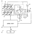
- FIG. 1 is a diagram showing the configuration of a driving apparatus in a first embodiment according to the present invention
- FIG. 2 is a flowchart showing control processing performed by a control circuit shown in FIG. 1 ;
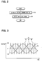
- FIG. 3 is a diagram showing a carrier wave and a voltage command wave for use in the control circuit shown in FIG. 1 ;
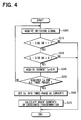
- FIG. 4 is a flowchart showing electric current calculation processing performed by the control circuit shown in FIG. 1 ;
- FIG. 5 is a diagram schematically showing an inverter circuit shown in FIG. 1 ;
- FIG. 6 is a diagram schematically showing the inverter circuit shown in FIG. 1 .
- FIG. 7 is a diagram schematically showing the inverter circuit shown in FIG. 1 ;
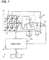
- FIG. 8 is a diagram showing the configuration of a driving apparatus in a second embodiment according to the present invention.
- FIG. 9 is a diagram schematically showing an inverter circuit shown in FIG. 8 ;
- FIG. 10 is a diagram schematically showing the inverter circuit shown in FIG. 8 ;
- FIG. 11 is a diagram schematically showing the inverter circuit shown in FIG. 8 ;
- FIG. 12 is a diagram showing the configuration of a driving apparatus in a third embodiment according to the present invention.
- FIG. 13 is a diagram schematically showing an inverter circuit shown in FIG. 12 ;
- FIG. 14 is a diagram schematically showing the inverter circuit shown in FIG. 12 ;
- FIG. 15 is a diagram schematically showing the inverter circuit shown in FIG. 12 ;
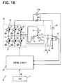
- FIG. 16 is a diagram showing the configuration of a driving apparatus in a fourth embodiment according to the present invention.
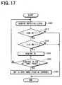
- FIG. 17 is a flowchart showing electric current calculation processing performed by a control circuit shown in FIG. 16 ;
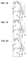
- FIG. 18 is a diagram schematically showing an inverter circuit shown in FIG. 16 ;
- FIG. 19 is a diagram schematically showing the inverter circuit shown in FIG. 16 ;
- FIG. 20 is a diagram schematically showing the inverter circuit shown in FIG. 16 ;
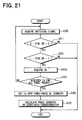
- FIG. 21 is a diagram showing the configuration of a driving apparatus in a fifth embodiment according to the present invention.
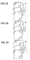
- FIG. 22 is a diagram schematically showing an inverter circuit shown in FIG. 21 ;
- FIG. 23 is a diagram schematically showing the inverter circuit shown in FIG. 21 ;
- FIG. 24 is a diagram schematically showing the inverter circuit shown in FIG. 21 ;
- FIG. 25 is a diagram showing the configuration of a driving apparatus in a sixth embodiment according to the present invention.
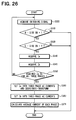
- FIG. 26 is a flowchart showing electric current calculation processing performed by a control circuit shown in FIG. 25 ;
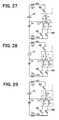
- FIG. 27 is a diagram schematically showing an inverter circuit shown in FIG. 25 ;
- FIG. 28 is a diagram schematically showing the inverter circuit shown in FIG. 25 ;
- FIG. 29 is a diagram schematically showing the inverter circuit shown in FIG. 25 ;
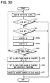
- FIG. 30 is a diagram showing the configuration of a driving apparatus in a seventh embodiment according to the present invention.
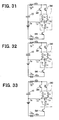
- FIG. 31 is a diagram schematically showing an inverter circuit shown in FIG. 30 .
- FIG. 32 is a diagram schematically showing the inverter circuit shown in FIG. 30 ;
- FIG. 33 is a diagram schematically showing the inverter circuit shown in FIG. 30 ;
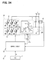
- FIG. 34 is a diagram showing the configuration of a driving apparatus in an eighth embodiment according to the present invention.
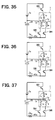
- FIG. 35 is a diagram schematically showing an inverter circuit shown in FIG. 34 ;
- FIG. 36 is a diagram schematically showing the inverter circuit shown in FIG. 34 ;
- FIG. 37 is a diagram schematically showing the inverter circuit shown in FIG. 34 ;
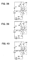
- FIG. 38 is a diagram showing the configuration of an inverter circuit in a ninth embodiment according to the present invention.
- FIG. 39 is a diagram schematically showing the inverter circuit shown in FIG. 38 ;
- FIG. 40 is a diagram schematically showing the inverter circuit shown in FIG. 38 ;
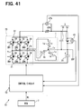
- FIG. 41 is a diagram showing the configuration of a driving apparatus in a tenth embodiment according to the present invention.
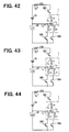
- FIG. 42 is a diagram schematically showing an inverter circuit shown in FIG. 41 ;
- FIG. 43 is a diagram schematically showing the inverter circuit shown in FIG. 41 ;
- FIG. 44 is a diagram schematically showing the inverter circuit shown in FIG. 41 ;
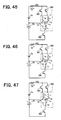
- FIG. 45 is a schematic diagram showing an inverter circuit in an eleventh embodiment according to the present invention.
- FIG. 46 is a schematic diagram showing the inverter circuit of the eleventh embodiment.
- FIG. 47 is a schematic diagram showing the inverter circuit of the eleventh embodiment.
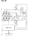
- FIG. 48 is a diagram showing the configuration of a driving apparatus in the twelfth embodiment according to the present invention.
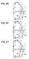
- FIG. 49 is a diagram schematically showing an inverter circuit shown in FIG. 48 ;
- FIG. 50 is a diagram schematically showing the inverter circuit shown in FIG. 48 ;
- FIG. 51 is a diagram schematically showing the inverter circuit shown in FIG. 48 ;
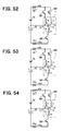
- FIG. 52 is a schematic diagram showing an inverter circuit in a thirteenth embodiment according to the present invention.
- FIG. 53 is a schematic diagram showing the inverter circuit of the thirteenth embodiment.
- FIG. 54 is a schematic diagram showing the inverter circuit of the thirteenth embodiment.
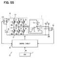
- FIG. 55 is a diagram showing the configuration of a driving apparatus in a fourteenth embodiment according to the present invention.
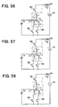
- FIG. 56 is a diagram schematically showing an inverter circuit shown in FIG. 55 ;
- FIG. 57 is a diagram schematically showing the inverter circuit shown in FIG. 55 ;
- FIG. 58 is a diagram schematically showing the inverter circuit shown in FIG. 55 ;
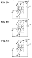
- FIG. 59 is a schematic diagram showing an inverter circuit in a fifteenth embodiment according to the present invention.
- FIG. 60 is a schematic diagram showing the inverter circuit of the fifteenth embodiment.
- FIG. 61 is a schematic diagram showing the inverter circuit of the fifteenth embodiment.
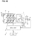
- FIG. 62 is a diagram showing the configuration of a driving apparatus in a sixteenth embodiment according to the present invention.
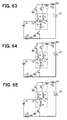
- FIG. 63 is a diagram schematically showing an inverter circuit shown in FIG. 62 ;
- FIG. 64 is a diagram schematically showing the inverter circuit shown in FIG. 62 ;
- FIG. 65 is a diagram schematically showing the inverter circuit shown in FIG. 62 ;
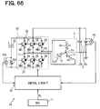
- FIG. 66 is a diagram showing the configuration of a driving apparatus in a seventeenth embodiment according to the present invention.
- FIG. 67 is a diagram schematically showing an inverter circuit shown in FIG. 66 ;
- FIG. 68 is a diagram schematically showing the inverter circuit shown in FIG. 66 ;
- FIG. 69 is a diagram schematically showing the inverter circuit shown in FIG. 66 ;
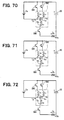
- FIG. 70 is a schematic diagram showing an inverter circuit in an eighteenth embodiment according to the present invention.
- FIG. 71 is a schematic diagram showing the inverter circuit of the eighteenth embodiment.
- FIG. 72 is a schematic diagram showing the inverter circuit of the eighteenth embodiment.
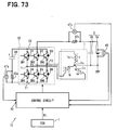
- FIG. 73 is a diagram showing the configuration of a driving apparatus in a nineteenth embodiment according to the present invention.
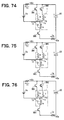
- FIG. 74 is a diagram schematically showing an inverter circuit shown in FIG. 73 ;
- FIG. 75 is a diagram schematically showing the inverter circuit shown in FIG. 73 ;
- FIG. 76 is a diagram schematically showing the inverter circuit shown in FIG. 73 ;
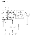
- FIG. 77 is a diagram showing the configuration of a driving apparatus in a twentieth embodiment according to the present invention.
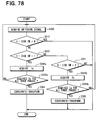
- FIG. 78 is a flowchart showing control processing performed by a control circuit shown in FIG. 77 ;
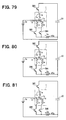
- FIG. 79 is a diagram schematically showing an inverter circuit shown in FIG. 77 ;
- FIG. 80 is a diagram schematically showing the inverter circuit shown in FIG. 77 ;
- FIG. 81 is a diagram schematically showing the inverter circuit shown in FIG. 77 ;
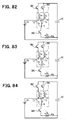
- FIG. 82 is a diagram schematically showing the inverter circuit shown in FIG. 77 ;
- FIG. 83 is a diagram schematically showing the inverter circuit shown in FIG. 77 ;
- FIG. 84 is a diagram schematically showing the inverter circuit shown in FIG. 77 ;
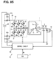
- FIG. 85 is a diagram showing the configuration of a driving apparatus in a twenty-first embodiment according to the present invention.
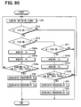
- FIG. 86 is a flowchart showing control processing performed by a control circuit shown in FIG. 85 ;
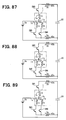
- FIG. 87 is a diagram schematically showing an inverter circuit shown in FIG. 85 ;
- FIG. 88 is a diagram schematically showing the inverter circuit shown in FIG. 85 ;
- FIG. 89 is a diagram schematically showing the inverter circuit shown in FIG. 85 ;
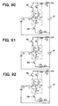
- FIG. 90 is a diagram schematically showing the inverter circuit shown in FIG. 85 ;
- FIG. 91 is a diagram schematically showing the inverter circuit shown in FIG. 85 ;
- FIG. 92 is a diagram schematically showing the inverter circuit shown in FIG. 85 ;
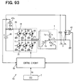
- FIG. 93 is a diagram showing the configuration of a driving apparatus in a twenty-second embodiment according to the present invention.
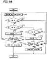
- FIG. 94 is a flowchart showing control processing performed by a control circuit shown in FIG. 93 ;
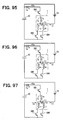
- FIG. 95 is a diagram schematically showing an inverter circuit shown in FIG. 93 ;
- FIG. 96 is a diagram schematically showing the inverter circuit shown in FIG. 93 ;
- FIG. 97 is a diagram schematically showing the inverter circuit shown in FIG. 93 ;
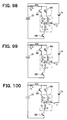
- FIG. 98 is a diagram schematically showing the inverter circuit shown in FIG. 93 ;
- FIG. 99 is a diagram schematically showing the inverter circuit shown in FIG. 93 ;
- FIG. 100 is a diagram schematically showing the inverter circuit shown in FIG. 93 ;
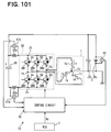
- FIG. 101 is a diagram showing the configuration of a driving apparatus in a twenty-third embodiment according to the present invention.
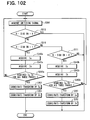
- FIG. 102 is a flowchart showing control processing performed by a control circuit shown in FIG. 101 ;
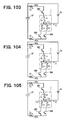
- FIG. 103 is a diagram schematically showing an inverter circuit shown in FIG. 101 ;
- FIG. 104 is a diagram schematically showing the inverter circuit shown in FIG. 101 ;
- FIG. 105 is a diagram schematically showing the inverter circuit shown in FIG. 101 ;
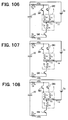
- FIG. 106 is a diagram schematically showing the inverter circuit shown in FIG. 101 ;
- FIG. 107 is a diagram schematically showing the inverter circuit shown in FIG. 101 ;
- FIG. 108 is a diagram schematically showing the inverter circuit shown in FIG. 101 .
- a driving apparatus for a three-phase AC synchronous motor is denoted by numeral 10 .
- the driving apparatus 10 outputs three-phase AC currents to the three-phase AC synchronous motor based on a DC voltage to drive the three-phase AC synchronous motor.
- a load for example a compressor device, is connected to an output shaft of rotation of the three-phase AC synchronous motor.
- the three-phase AC synchronous motor includes a rotor (not shown), for example having a permanent magnet embedded therein and a stator coil 1 providing a rotating magnetic field to the rotor.
- the stator coil 1 has a U-phase coil 1 a , a V-phase coil 1 b and a, W-phase coil 1 c , which are star-connected to a neutral point 1 x .
- a DC power source 3 is placed between the neutral point 1 x of the stator coil 1 and the ground.
- the DC power source, 3 is formed of a battery 3 a and a capacitor 3 b.
- the three-phase AC synchronous motor in the present embodiment has a structure which has no sensor for detecting the position information of the rotor.
- the driving apparatus 10 includes an inverter circuit 20 , a capacitor 30 , a resistor 40 , voltage sensors 45 and 47 a and a control circuit 50 .
- the inverter circuit 20 outputs three-phase AC currents iu, iv and iw to the stator coil 1 based on an output voltage from the DC power source 3 and a difference in voltage between the positive electrode and the negative electrode of the capacitor 30 .
- the inverter circuit 20 is formed, of transistors SW 1 to SW 6 and diodes D 1 , D 2 , D 3 , D 4 , D 5 and D 6 .
- the transistors SW 1 and SW 4 are connected in series directly to each other between a negative-pole bus 21 and a positive-pole bus 22 .
- the transistors SW 2 and SW 5 are connected in series directly to each other between the negative-pole bus 21 and the positive-pole bus 22 .
- the transistors SW 3 and SW 6 are connected in series directly to each other between the negative-pole bus 21 and the positive-pole bus 22 .
- the negative-pole bus 21 is connected to the ground.
- the transistors SW 1 and SW 4 are provided in a pair in association with the W-phase and a common connection point T 1 of the transistors SW 1 and SW 4 is connected to the W-phase coil 1 c .
- the transistors SW 2 and SW 5 are provided in a pair in association with the V-phase and a common connection point T 2 of the transistors SW 2 and SW 5 is connected to the V-phase coil 1 b .
- the transistors SW 3 and SW 6 are provided in a pair in association with the U-phase and a common connection point T 3 of the transistors SW 3 and SW 6 is connected to the U-phase coil 1 a .
- the pairs of the transistors are connected in parallel between the negative-pole bus 21 and the positive-pole bus 22 .
- Each of the transistors SW 1 to S 6 is formed by using a semiconductor transistor such as an insulated gate bipolar transistor or a field-effect transistor.
- Each of the diodes D 1 , D 2 , D 3 , D 4 , D 5 and D 6 is placed in inverse-parallel with the associated one of the transistors SW 1 to SW 6 .
- the capacitor 30 provides an output voltage to the inverter circuit 20 together with the battery 3 a .
- the positive electrode of the capacitor 30 is connected to the positive-pole bus 22 of the inverter circuit 20 .
- the negative electrode of the capacitor 30 is connected to the neutral point 1 x.
- the resistor 40 a is connected between the negative-pole bus 21 and a negative electrode of the battery 3 a , that is, to the ground.
- the resistor 40 a is used for acquiring a U-phase electric current iu, a V-phase electric current iv and a W-phase electric current iw as described below.
- the U-phase electric current iu is a phase electric current, which flows from the common connection point T 3 of the transistors SW 3 and SW 6 to the U-phase coil 1 a .
- the V-phase electric current iv is a phase electric current, which flows from the common connection point T 2 of the transistors SW 2 and SW 5 to the V-phase coil 1 b .
- the W-phase electric current iw is a phase electric current, which flows from the common connection point T 1 of the transistors SW 1 and SW 4 to the W-phase coil 1 c.
- the directions of the flow of the electric currents iu, iv and iw are defined such that arrows indicate a positive direction.
- the voltage sensor 45 detects a potential difference between a positive electrode and the negative electrode of the DC power source 3 .
- the voltage sensor 47 a detects a potential difference between one terminal and the other terminal of the resistor 40 .
- the control circuit 50 is formed of a microcomputer and a memory and as described below, performs processing of controlling the transistors SW 1 to SW 6 based on the respective values detected by the sensors 45 and 47 a and the target number of revolution Nt provided by an electronic control unit (ECU) 7 .
- ECU electronice control unit
- the control circuit 50 performs control processing of a conventional triangular wave comparison method in accordance with a flowchart of FIG. 2 .
- the control processing of the conventional triangular wave comparison method involves control of the inverter circuit 20 based on a comparison between a voltage command wave VS for each phase and a carrier wave Ka.
- FIG. 3 shows the carrier wave Ka.
- the carrier wave Ka is a triangular wave representing a voltage, which periodically changes from zero potential (0) toward a positive or negative side.
- the value detected by the voltage sensor 45 is set to a peak value VB of the carrier wave Ka.
- the control circuit 50 calculates the voltage command wave for each phase for controlling an actual number of revolution (actual rotation speed) Na of the three-phase AC motor to a target number of revolution (target rotation speed) Nt of the same.
- the voltage command wave VS for each phase shows a voltage command value for each of the coils 1 a , 1 b and 1 c and is three-phase command waves formed of a U-phase command wave VU, a V-phase command wave W and a W-phase command wave VW as shown in FIG. 3 .
- Each of the voltage command waves VU, W and VW is a sinusoidal wave representing a voltage, which periodically changes from zero potential toward a positive or negative side. As described below, the waves VU, W and VW are used in controlling the inverter circuit 20 .
- a conventional voltage equation for a motor is used in the calculation of the voltage command wave for each phase.
- the voltage equation represents a relationship between an armature voltage for each phase produced in each of the coils 1 a , 1 b and 1 c and each of the phase electric currents iu, iv and iw.
- each of the phase electric currents iu, iv and iw is substituted into the voltage equation to calculate the armature voltage for each phase and the calculated armature voltage is used as the voltage command wave for each phase.
- the phase electric currents iu, iv and iw are acquired through electric current calculation processing described below.
- a switching signal for controlling the inverter circuit 20 is acquired by using the voltage command wave VS.
- the voltage command wave VS and the carrier wave Ka is compared for each wave to determine which of the transistors SW 1 to SW 6 should be turned on.
- the U-phase command wave VU is associated with the transistors SW 3 and SW 6 .
- the transistor SW 3 on the side of the positive-pole bus 22 that is, the high-potential side
- the transistor SW 6 on the side of the negative-pole bus 21 that is, the low-potential side
- the U-phase command wave VU is smaller than the carrier wave Ka
- the transistor SW 3 should be turned off and the transistor SW 6 should be turned on.
- the V-phase command wave W is associated with the transistors SW 2 and SW 5 .
- one of the transistor SW 2 on the side of the positive-pole bus 22 and the transistor SW 5 on the side of the negative-pole bus 21 should be turned off and the other transistor should be turned on in accordance with the result of a comparison between the V-phase command wave W and the carrier wave Ka.
- one of the transistor SW 1 on the side of the positive-pole bus 22 and the transistor SW 4 on the side of the negative-pole bus 21 should be turned off and the other transistor should be turned on in accordance with the result of a comparison between the W-phase command wave VW and the carrier wave Ka.
- the control circuit 50 determines in this manner which one of the transistors SW 1 to SW 6 should be turned on and calculates the switching signal containing the information of the determination.
- step S 100 the processing returns to step S 100 and repeats the processing at steps S 100 and S 200 to acquire a control signal for the inverter circuit 20 repeatedly.
- the switching signals acquired as described above are output to the inverter circuit 20 .
- This causes switching operation of the transistors SW 1 to SW 6 .
- three-phase AC currents are output to the stator coil 1 from the common connection points T 1 , T 2 and T 3 .
- a rotating magnetic field is produced from the stator coil 1 .
- the rotor rotates in synchronization with the rotating magnetic field.
- the electric current flows from the W-phase coil 1 c toward the positive-pole bus 22 through the diode D 1 when the transistor SW 4 is turned off.
- the electric current flows toward the positive electrode of the capacitor 30 as a charge electric current and accumulates electric charge on the capacitor 30 .
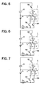
- FIG. 5 shows a schematic diagram of the inverter circuit 20 when the transistors SW 3 , SW 4 and SW 5 are ON among the transistors SW 1 to SW 6 .
- the transistors SW 1 , SW 2 , SW 6 and the diodes D 1 to D 6 are not shown.
- FIG. 6 shows a schematic diagram of the inverter circuit 20 when the transistors SW 2 , SW 4 and SW 6 are ON among the transistors SW 1 to SW 6 .
- the transistors SW 1 , SW 3 , SW 5 and the diodes D 1 to D 6 are not shown.
- FIG. 7 shows a schematic diagram of the inverter circuit 20 when the transistors SW 1 , SW 5 and SW 6 are ON among the transistors SW 1 to SW 6 .
- the transistors SW 2 , SW 3 , SW 4 and the diodes D 1 to D 6 are not shown.
- the direction of the flow of the electric current Ia is defined such that arrows indicate the positive direction.
- FIG. 4 is a flowchart showing the electric current calculation processing.
- the control circuit 50 performs the electric current calculation processing in accordance with the flowchart of FIG. 4 .
- the electric current calculation processing is repeatedly performed and the performance of the electric current calculation processing is started each time the switching signal is calculated at step S 200 described above. Specifically, the electric current calculation processing is performed each time the transistor to be turned on is changed among the transistors SW 1 to SW 6 .
- the switching signal is acquired.
- step S 320 it is checked, on the basis of the switching signal whether the number of ON transistors (denoted as ON number in FIG. 4 ) among the transistors SW 4 , SW 5 and SW 6 (denoted as low potential side (L-side) SWs in FIG. 4 ) is two or not.
- step S 330 It is then determined that the number of ON transistors among the transistors SW 4 , SW 5 and SW 6 is two and YES is produced at step S 330 . This is because the transistors SW 4 and SW 5 are ON among the transistors SW 4 , SW 5 and SW 6 .
- an electric current (iv+iw) provided by adding the V-phase electric current iv to the W-phase electric current iw flows as the electric current Ia through the resistor 40 a .
- the electric current (iv+iw) is equal to ⁇ (in+iu).
- the processing proceeds to step S 340 to acquire ⁇ (in+iu) as a current value V/R provided by dividing a voltage V detected by the voltage sensor 47 a by a resistance value R of the resistor 40 a.
- step S 350 it is checked whether the electric current Ia flowing through the resistor 40 a has been acquired for all the three-phases or not. Since the electric current Ia has been acquired only for the U-phase at this point ( FIG. 5 ), it is determined that the electric current Ia has not been acquired for all the three phases yet and NO is produced. Then, the processing returns to step S 300 .
- the switching signal is acquired at step S 300 , it is determined based on the switching signal that the number of ON transistors among the transistors SW 1 , SW 2 and SW 3 is one and YES is produced at step S 310 .
- step S 320 it is determined that the number of ON transistors among the transistors SW 4 , SW 5 and SW 6 is two and YES is produced. This is because the transistors SW 4 and SW 6 are ON among the transistors SW 4 , SW 5 and SW 6 .
- step S 340 acquires ⁇ (in+iv) as the value V/R provided by dividing the voltage V detected by the voltage sensor 47 a by the resistance value R of the resistor 40 a.
- step S 350 it is checked whether the electric current Ia flowing through the resistor 40 a has been acquired for the three phases or not. Since the electric current Ia has been acquired only for the U-phase and the V-phase at this point ( FIG. 6 ), it is determined that the electric current Ia has not been acquired for all the three phases yet and NO is produced. Then, the processing returns to step S 300 .
- the switching signal is acquired at step S 300 and the control processing proceeds to the next step S 310 . It is determined that the number of ON transistors among the transistors SW 1 , SW 2 and SW 3 is one and YES is produced at step S 310 . At the next step S 320 , it is determined that the number of ON transistors among the transistors SW 4 , SW 5 and SW 6 is two and YES is produced.
- step S 340 acquires ⁇ (in+iw) as the value V/R provided by dividing the voltage V detected by the voltage sensor 47 a by the resistance value R of the resistor 40 a.
- next step S 350 it is determined that the electric current Ia flowing-through the resistor 40 a has been acquired for all the three phases and YES is produced.
- the control processing proceeds to the next step S 360 to set the electric current Ia for all the three phases acquired at the step S 340 together into three-phase AC currents ⁇ (in+iu), ⁇ (in+iv), ⁇ (in+iw) ⁇ of a three-phase fixed coordinate system.
- the three-phase AC currents of the three-phase fixed coordinate system is coordinate-transformed to calculate the phase electric currents iu, iv, iw.
- the electric currents iva, iva and iwa can be transformed from the three-phase fixed coordinate system to the AC currents of the two-phase fixed coordinate system in this manner to acquire the AC currents i ⁇ and i ⁇ of the two-phase fixed coordinate system excluding the neutral-point electric current in.
- the AC currents i ⁇ and i ⁇ of the two-phase fixed coordinate system are transformed into electric currents of the three-phase fixed coordinate system to acquire electric currents iu, iv and iw excluding the neutral-point electric current in for each phase from the electric currents iva, iva and iwa.
- the electric currents iu, iv and iw thus acquired are used as the three-phase AC current for calculating the voltage command wave for each phase at step S 100 described above.
- the control circuit 50 when the control circuit 50 has acquired the electric current Ia flowing through the resistor 40 a for the three-phases, the circuit 50 brings the electric current Ia for the three-phases together into the three-phase AC currents iva, iva and iwa of the three-phase fixed coordinate system. In addition, the control circuit 50 transforms the three-phase AC currents of the three-phase fixed coordinate system into the AC currents of the two-phase fixed coordinate system.
- control circuit 50 transforms the AC currents of the two-phase fixed coordinate system into the three-phase AC currents of the three-phase fixed coordinate system to acquire the electric currents iu, iv and iw excluding the neutral-point electric current in for each phase from the electric currents iva, iva and iwa. Then, the control circuit 50 uses the electric currents iu, iv and iw to acquire the voltage command wave for each phase and controls the inverter circuit 20 based on the voltage command wave for each phase. In this manner, the three-phase AC synchronous motor can be controlled by using the three-phase AC currents iva, iva and iwa through the inverter circuit 20 .
- the single resistor 40 a and the single voltage sensor 47 a are used in order to acquire the three-phase AC currents iva, iva and iwa.
- Some conventional driving apparatuses for three-phase AC synchronous motors employ three resistors and three voltage sensors in order to detect three-phase AC output currents from the inverter circuit 20 to the stator coil 1 .
- the single resistor 40 a and the single voltage sensor 47 a are used as described above in the present embodiment. This can reduce the number of resistors and the number of voltage sensors.
- the first embodiment described above is an example, in which the voltage command wave for each phase is calculated by using the electric currents iu, iv and iw excluding the neutral-point electric current in for each phase from the three-phase AC currents (iva, iva, iwa).
- the voltage command wave for each phase may be calculated by using three-phase AC currents (iva, iva, iwa) including the neutral-point electric current in for each phase.
- the present invention is not limited thereto.
- AC currents of the two-phase fixed coordinate system or electric currents of a rotational coordinate system may be used to acquire the voltage command wave VS.
- the first embodiment has shown the example, in which the three-phase AC currents iva, iva and iwa are coordinate-transformed to acquire the electric currents iu, iv and iw excluding the neutral-point electric current in for each phase from the three-phase AC currents iva, iva and iwa.
- the neutral-point electric current in is detected and the detected neutral-point electric current in is used to exclude the neutral-point electric current in for each phase from three-phase AC currents iva, iva and iwa.
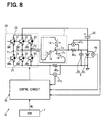
- FIG. 8 shows the circuit configuration of the driving apparatus 10 in the present embodiment.
- the driving apparatus 10 in FIG. 8 is provided by adding a resistor 40 c and a voltage sensor 47 c to the driving apparatus 10 shown in FIG. 1 .
- the resistor 40 c is connected between the neutral point 1 x of the stator coil 1 and the positive electrode of the battery 3 a .
- the resistor 40 c is used for detecting the neutral-point electric current in.
- the voltage sensor 47 c detects a potential difference between one terminal and the other terminal of the resistor 40 c.
- FIG. 9 shows a schematic diagram of the inverter circuit 20 when the transistors SW 3 , SW 4 and SW 5 are ON among the transistors SW 1 to SW 6 and also shows the stator coil 1 .
- FIG. 10 shows a schematic diagram of the inverter circuit 20 when the transistors SW 2 , SW 4 and SW 6 are ON and also shows the stator coil 1 .
- FIG. 11 shows a schematic diagram of the inverter circuit 20 when the transistors SW 1 , SW 5 and SW 6 are ON and also shows the stator coil 1 .
- the electric current ⁇ (in+iu) can be acquired as a value V/R provided by dividing the voltage V detected by the voltage sensor 47 a by the resistance value R of the resistor 40 a similarly to the first embodiment described above.
- the neutral-point electric current in is acquired as the value V/R provided by dividing the voltage V detected by the voltage sensor 47 c by the resistance value R of the resistor 40 c.
- the neutral-point electric current in is used to acquire the electric current ⁇ iu excluding the electric current ⁇ in from the electric current (in+iu) acquired as described above.
- the electric current ⁇ iu can be multiplied by ⁇ 1 to acquire the U-phase electric current iu.
- the electric current (in+iv) can be acquired as the value V/R provided by dividing the voltage V detected by the voltage sensor 47 a by the resistance value R of the resistor 40 a , similarly to the first embodiment described above.
- the neutral-point electric current in is acquired as the value V/R provided by dividing the voltage V detected by the voltage sensor 47 c by the resistance value R of the resistor 40 c.
- the neutral-point electric current in is used to acquire the electric current ⁇ iv excluding the electric current ⁇ in from the electric current (in+iv) acquired as described above.
- the electric current ⁇ iv can be multiplied by ⁇ 1 to acquire the V-phase electric current iv.
- the electric current (in+iw) can be acquired as the value V/R provided by dividing the voltage V detected by the voltage sensor 47 a by the resistance value R of the resistor 40 a , similarly to the first embodiment described above.
- the neutral-point electric current in is acquired as the value V/R provided by dividing the voltage V detected by the voltage sensor 47 c by the resistance value R of the resistor 40 c.
- the neutral-point electric current in is used to acquire the electric current ⁇ iw excluding the electric current ⁇ in from the electric current (in+iw) acquired as described above.
- the electric current ⁇ iw can be multiplied by ⁇ 1 to acquire W-phase electric current iw.
- the U-phase electric current iu, the V-phase electric current iv and the W-phase electric current iw thus acquired are set together into the three-phase AC currents.
- the three-phase AC currents are used to calculate the voltage command wave for each phase.
- control circuit 50 can acquire the three-phase AC currents iu, iv and iw and can use the acquired three-phase AC currents iu, iv and iw to control the three-phase AC synchronous motor through the inverter circuit 20 , similarly to the first embodiment described above.
- the first and second embodiments described above have shown the examples, in which the electric current including the neutral-point electric current in added to the phase electric current is detected for each phase as the electric current Ia flowing through the resistor 40 a .
- the phase electric current is detected as the electric current Ia flowing through the resistor 40 a.
- the circuit configuration of the driving apparatus 10 in the present embodiment is identical to the circuit configuration of the driving apparatus 10 in the first embodiment described above.
- Control processing performed by the control circuit 50 in the present embodiment will be described below with reference to FIGS. 12 to 15 .
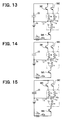
- FIG. 13 shows a schematic diagram of the inverter circuit 20 when transistors SW 1 , SW 2 and SW 6 are ON among transistors SW 1 to SW 6 .
- the transistors SW 3 , SW 4 , SW 5 and the diodes D 1 to D 6 are not shown.
- FIG. 14 shows a schematic diagram of the inverter circuit 20 when the transistors SW 1 , SW 3 and SW 5 are ON among the transistors SW 1 to SW 6 .
- FIG. 15 shows a schematic diagram of the inverter circuit 20 when the transistors SW 2 , SW 3 and SW 4 are ON among the transistors SW 1 to SW 6 .
- the transistors SW 1 , SW 5 , SW 6 and the diodes D 1 to D 6 are not shown.
- the direction of the flow of the electric current Ia is defined such that arrows indicate a positive direction.
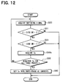
- FIG. 12 is a flowchart showing electric current calculation processing performed by the control circuit 50 in the present embodiment.
- the control circuit 50 performs the electric current calculation processing in accordance with the flowchart of FIG. 12 .
- the switching signal is acquired.
- step S 321 it is checked, on the basis of the switching signal whether the number of ON transistors (denoted as ON number in FIG. 12 ) among the transistors SW 4 , SW 5 and SW 6 (denoted as low or L-side SWs in FIG. 12 ) is one or not.
- the U-phase electric current iu flows as the electric current Ia through the resistor 40 a .
- the control processing proceeds to the next step S 340 a to acquire the electric current iu as the value V/R provided by dividing the voltage V detected by the voltage sensor 47 a by the resistance value R of the resistor 40 a.
- step S 350 it is checked whether or not the electric current Ia flowing through the resistor 40 a has been acquired for the three-phases. Since the electric current Ia has been acquired only for the U-phase at this point, it is determined that the electric current Ia has not been acquired for the three phases yet and NO is produced.
- step S 300 the processing returns to step S 300 to acquire the switching signal.
- the transistors SW 1 , SW 3 and SW 5 are ON at this point among the transistors SW 1 to SW 6 , it is determined that the number of ON transistors among the transistors SW 1 , SW 2 and SW 3 is two and YES is produced at the next step S 311 .
- the electric current iv flows as the electric current Ia through the resistor 40 a .
- the control processing proceeds to the next step S 341 to acquire the V-phase electric current iv as the value V/R provided by dividing the voltage V detected by the voltage sensor 47 a by the resistance value R of the resistor 40 a.
- step S 300 the processing returns to step S 300 to acquire the switching signal.
- the transistors SW 2 , SW 3 and SW 4 are ON at this point among the transistors SW 1 to SW 6 , it is determined that the number of ON transistors among the transistors SW 1 , SW 2 and SW 3 is two and YES is produced at the next step S 311 . It is determined that the number of ON transistors among the transistors SW 4 , SW 5 and SW 6 is one and YES is produced at the next step S 321 .
- the electric current iw flows as the electric current Ia through the resistor 40 a .
- the control processing proceeds to the next step S 340 a to acquire the W-phase electric current iw as the value V/R provided by dividing the voltage V detected by the voltage sensor 47 a by the resistance value R of the resistor 40 a.
- next step S 350 It is determined that the electric current Ia flowing through the resistor 40 a has been acquired for the three-phases and YES is produced at the next step S 350 .
- the control processing proceeds to the next step S 360 to bring the electric current Ia for the three-phases acquired at the step S 340 a together into three-phase AC currents iu, iv and iw.
- the control circuit 50 acquires the phase electric currents iu, iv and iw as the electric current Ia flowing through the resistor 40 a and brings the phase electric currents iu, iv and iw together into the three-phase AC currents. Therefore, similarly to the first embodiment described above, the three-phase AC synchronous motor can be controlled through the inverter circuit 20 by using the three-phase AC output from the inverter circuit 20 to the stator coil 1 .
- the control circuit 50 may calculate, for each phase, average values of the phase electric currents iu, iv and iw acquired at step S 360 in the third embodiment described above and the phase electric currents iu, iv and iw acquired in the first embodiment described above and may use the average values of the phase electric currents to drive the three-phase AC synchronous motor through the inverter circuit 20 .
- the first to third embodiments described above have shown the examples, in which the resistor 40 a is placed between the negative-pole bus 21 of the inverter circuit 20 and the negative electrode of the battery, 3 a .
- a resistor 40 b is placed between the positive-pole bus 22 of the inverter circuit 20 and the positive electrode of the capacitor 30 as shown in FIG. 16 .
- the resistor 40 b and a voltage sensor 47 b are provided instead of the resistor 40 a and the voltage sensor 47 a in FIG. 1 .
- the resistor 40 b is placed between the positive-pole bus 22 of the inverter circuit 20 and the positive electrode of the capacitor 30 .
- the voltage sensor 47 b detects a potential difference between one terminal and the other terminal of the resistor 40 b.
- control processing performed by the control circuit 50 in the present embodiment will be described with reference to FIGS. 17 to 20 .
- FIG. 18 shows a schematic diagram of the inverter circuit 20 when the transistors SW 3 , SW 4 and SW 5 are ON among the transistors SW 1 to SW 6 .
- the transistors SW 1 , SW 2 , SW 6 and the diodes D 1 to D 6 are not shown.
- FIG. 19 shows a schematic diagram of the inverter circuit 20 when the transistors SW 2 , SW 4 and SW 6 are ON among the transistors SW 1 to SW 6 .
- the transistors SW 1 , SW 3 , SW 5 and the diodes D 1 to D 6 are not shown.
- FIG. 20 shows a schematic diagram of the inverter circuit 20 when the transistors SW 1 , SW 5 and SW 6 are ON among the transistors SW 1 to SW 6 .
- the transistors SW 2 , SW 3 , SW 4 and the diodes D 1 to D 6 are not shown.
- the direction of the flow of an electric current Ib is defined such that arrows indicate a positive direction.
- FIG. 17 is a flowchart showing electric current calculation processing performed by the control circuit 50 in the present embodiment.
- the control circuit 50 performs the electric current calculation processing in accordance with the flowchart of FIG. 17 .
- reference numerals identical to those in FIG. 4 represent the same steps and the description thereof is omitted.
- the switching signal is acquired.
- the transistors SW 3 , SW 4 and SW 5 are ON at this point among the transistors SW 1 to SW 6 , it is determinedthat the number of ON transistors (denoted as ON number in FIG. 17 ) among the transistors SW 1 , SW 2 and SW 3 (denoted as high-side SWs in FIG. 17 ) is one and YES is produced at the next step S 310 .
- the control processing proceeds to the next step S 345 to acquire the U-phase electric current iu as the value V/R provided by dividing the voltage V detected by the voltage sensor 47 b by the resistance value R of the resistor 40 b.
- step S 300 the processing returns to step S 300 to acquire the switching signal.
- the transistors SW 2 , SW 4 and SW 6 are ON at this point among the transistors SW 1 to SW 6 , it is determined that the number of ON transistors of the transistors SW 1 , SW 2 and SW 3 is one and YES is produced at the next step S 310 . It is determined that the number of ON transistors among the transistors SW 4 , SW 5 and SW 6 is two and YES is produced at step S 320 .
- the control processing proceeds to the next step S 345 to acquire the V-phase electric current iv as the value V/R provided by dividing the voltage V detected by the voltage sensor 47 b by the resistance value R of the resistor 40 b.
- step S 300 the processing returns to step S 300 to acquire the switching signal.
- the transistors SW 1 , SW 5 and SW 6 are ON at this point among the transistors SW 1 to SW 6 , it is determined that the number of ON transistors among the transistors SW 1 , SW 2 and SW 3 is two and YES is produced at the next step S 310 . It is determined that the number of ON transistors among the transistors SW 4 , SW 5 and SW 6 is one and YES is produced at the next step S 320 .
- the control processing proceeds to the next step S 345 to acquire the W-phase electric current iw as the value V/R provided by dividing the voltage V detected by the voltage sensor 47 b by the resistance value R of the resistor 40 b.
- next step S 350 It is determined that the electric current Ib flowing through the resistor 40 b has been acquired for the three-phases and YES is produced at the next step S 350 .
- the control processing proceeds to the next step S 360 to bring the electric currents Ib for the three-phases acquired at the step S 345 together into three-phase AC currents iu, iv and iw.
- the control circuit 50 detects the phase electric currents iu, iv and iw as the electric currents Ib flowing through the resistor 40 b .
- the three-phase AC currents iu, iv and iw are acquired similarly to the first embodiment described above.
- the control circuit 50 can control the three-phase AC synchronous motor based on the electric currents iu, iv and iw through the inverter circuit 20 .
- the fourth embodiment described above is an example, in which the phase electric current is detected for each phase as the electric current Ib flowing through the resistor 40 b .
- the electric current including the neutral-point electric current in added to the phase electric current is detected for each phase as the electric current Ib flowing through the resistor 40 b.
- the circuit configuration of the control circuit 50 in the present embodiment is identical to the circuit configuration in the fourth embodiment described above.
- Control processing performed by the control circuit 50 in the present embodiment will be described below with reference to FIGS. 21 to 24 .
- FIG. 22 shows a schematic diagram of the inverter circuit 20 when the transistors SW 1 , SW 2 and SW 6 are ON among the transistors SW 1 to SW 6 .
- the transistors SW 3 , SW 4 , SW 5 and the diodes D 1 to D 6 are not shown.
- FIG. 23 shows a schematic diagram of the inverter circuit 20 when the transistors SW 1 , SW 3 and SW 5 are ON among the transistors SW 1 to SW 6 .
- the transistors SW 2 , SW 4 , SW 6 and the diodes D 1 to D 6 are not shown.
- FIG. 24 shows a schematic diagram of the inverter circuit 20 when the transistors SW 2 , SW 3 and SW 4 are ON among the transistors SW 1 to SW 6 .
- the transistors SW 1 , SW 5 , SW 6 and the diodes D 1 to D 6 are not shown.
- the direction of the flow of the electric current Ib is defined such that arrows indicate a positive direction.
- FIG. 21 is a flowchart showing electric current calculation processing performed by the control circuit 50 in the present embodiment.
- the control circuit 50 performs the electric current calculation processing in accordance with the flowchart of FIG. 21 .
- reference numerals identical to those in FIG. 12 represent the same steps and the description thereof is omitted.
- step S 300 the switching signal is acquired.
- the transistors SW 1 , SW 2 and SW 6 are ON among the transistors SW 1 to SW 6 , it is determined that the number of ON transistors (denoted as ON number in FIG. 21 ) among the transistors SW 1 , SW 2 and SW 3 (denoted as high-side SWs in FIG. 21 ) is two and YES is produced at the next step S 311 .
- the control processing proceeds to the next step S 340 a to acquire ⁇ (in+iu) as the value V/R provided by dividing the voltage V detected by the voltage sensor 47 b by the resistance value R of the resistor 40 b.
- step S 300 the processing returns to step S 300 to acquire the switching signal.
- the transistors SW 1 , SW 3 and SW 5 are ON at this point among the transistors SW 1 to SW 6 , it is determined that the number of ON transistors among the transistors SW 1 , SW 2 and SW 3 is two and YES is produced at the next step S 311 . It is determined that only the transistor SW 5 is ON among the transistors SW 4 , SW 5 and SW 6 and that the number of ON transistors among the transistors SW 4 , SW 5 and SW 6 is one and YES is produced at step 5321 .
- the control processing proceeds to the step S 345 a to acquire ⁇ (in+iv) as the value V/R provided by dividing the voltage V detected by the voltage sensor 47 b by the resistance value R of the resistor 40 b.
- step S 300 the processing returns to step S 300 to acquire the switching signal.
- the transistors SW 2 , SW 3 and SW 4 are ON at this point among the transistors SW 1 to SW 6 , it is determined that the number of ON transistors among the transistors SW 1 , SW 2 and SW 3 is two and YES is produced at the next step S 311 . It is determined that the number of ON transistors among the transistors SW 4 , SW 5 and SW 6 is one and YES is produced at the next step S 321 .
- the control processing proceeds to the step S 345 a to acquire ⁇ (in+iw) as the value V/R provided by dividing the voltage V detected by the voltage sensor 47 b by the resistance value R of the resistor 40 b.
- the three-phase AC current of the three-phase fixed coordinate system is coordinate-transformed to acquire the AC currents i ⁇ and i ⁇ of the two-phase fixed coordinate system.
- the AC currents i ⁇ and i ⁇ of the two-phase fixed coordinate system excluding the neutral-point electric current in for each phase can be acquired, similarly to the first embodiment described above.
- the AC currents i ⁇ and i ⁇ of the two-phase fixed coordinate system can be transformed into electric currents of the three-phase fixed coordinate system to acquire electric currents iu, iv and iw excluding the neutral-point electric current in for each phase from the electric currents Ib for the three-phases.
- the control circuit 50 acquires the electric currents Ib flowing through the resistor 40 b for the three-phases, brings the electric currents Ib for the three-phases together into the three-phase AC currents of the three-phase fixed coordinate system and coordinate-transforms the three-phase AC currents of the three-phase fixed coordinate system to acquire the three-phase AC currents iu, iv and iw. Furthermore, the control circuit 50 can control the three-phase AC synchronous motor based on the electric currents iu, iv and iw through the inverter circuit 20 .
- the control circuit 50 may calculate, for each phase, average values of the phase electric currents iu, iv and iw acquired at step S 370 in the fifth embodiment described above and the phase electric current iu, iv and iw acquired in the fourth embodiment described above and may use the average values of the phase electric currents to acquire the voltage command wave for each phase.
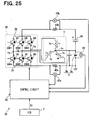
- FIG. 25 shows the circuit configuration of the driving apparatus 10 according to the sixth embodiment.
- FIG. 25 shows the configuration, in which the resistor 40 b and the voltage sensor 47 b are added to the circuit configuration shown in FIG. 1 .
- the resistor 40 b is placed between the positive-pole bus 22 of the inverter circuit 20 and the positive electrode of the capacitor 30 similarly to theourth embodiment described above.
- the voltage sensor 47 b detects a potential difference between one terminal and the other terminal of the resistor 40 b similarly to the fourth embodiment described above.
- control processing performed by the control circuit 50 in the present embodiment will be described below with reference to FIGS. 26 to 29 .
- FIG. 27 shows a schematic diagram of the inverter circuit 20 when transistors SW 3 , SW 4 and SW 5 are ON among the transistors SW 1 to SW 6 and also shows the stator coil 1 .
- FIG. 28 shows a schematic diagram of the inverter circuit 20 when the transistors SW 2 , SW 4 and SW 6 are ON among the transistors SW 1 to SW 6 and also shows the stator coil 1 .
- FIG. 29 shows a schematic diagram of the inverter circuit 20 when the transistors SW 1 , SW 5 and SW 6 are ON among the transistors SW 1 to SW 6 and also shows the stator coil 1 .
- FIG. 26 is a flowchart showing electric current calculation processing performed by the control circuit 50 in the present embodiment.
- the control circuit 50 performs the electric current calculation processing in accordance with the flowchart of FIG. 26 .
- reference numerals identical to those in FIG. 4 represent the same steps and the description thereof is omitted.
- step S 300 the switching signal is acquired.
- the transistors SW 3 , SW 4 and SW 5 are ON at this point among the transistors SW 1 to SW 6 , it is determined that the number of ON transistors (denoted as ON number in FIG. 26 ) among the transistors SW 1 , SW 2 and SW 3 (denoted as high-side SWs in FIG. 26 ) is one and YES is produced at the next step S 310 .
- the electric current Ia is acquired as ⁇ (in+iu) at step S 340 .
- the electric current Ia is equal to the value V/R provided by dividing the voltage V detected by the voltage sensor 47 a by the resistance value R of the resistor 40 a.
- the electric current Ib is acquired as the U-phase electric current iu at step S 345 .
- the electric current Ib is equal to the value V/R provided by dividing the voltage V detected by the voltage sensor 47 b by the resistance value R of the resistor 40 b.
- the electric current Ia is acquired as the electric current (in+iv) at step S 340 .
- the electric current Ib is acquired as the V-phase electric current iv at step S 345 .
- the electric current Ia is acquired as the electric current (in+iw) at step S 340 .
- the electric current Ib is acquired as the W-phase electric current iw at step S 345 .
- the control processing proceeds to the next step S 361 .
- the electric current Ia for the three-phases acquired at the step S 340 are set together into three-phase AC currents iva, iva and iwa of the three-phase fixed coordinate system and the three-phase AC currents iva, iva and iwa are coordinate-transformed to provide three-phase AC currents iu, iv and iw excluding neutral-point electric current in for each phase from the electric currents iva, iva and iwa.
- the electric currents Ib for the three-phases acquired at the step S 345 are set together into three-phase AC currents iu, iv and iw of the three-phase fixed coordinate system.
- the control circuit 50 calculates, for each phase, average values of the phase electric currents iu, iv and iw acquired at step S 361 and the phase electric currents iu, iv and iw acquired at step S 362 .
- the control circuit 50 uses the calculated average values of the phase electric currents to acquire the voltage command wave for each phase.
- the control circuit 50 uses the voltage command wave for each phase to acquire the switching signal similarly to the first embodiment described above. Then, the switching signals are output to the inverter circuit 20 to perform the switching operation of the transistors SW 1 to SW 6 .
- the control circuit 50 calculates the average values of the three-phase AC currents acquired by using the electric current Ia flowing through the resistor 40 a and the three-phase AC currents acquired by using the electric current Ib flowing through the resistor 40 b .
- the circuit 50 uses the calculated average values to acquire the voltage command wave for each phase.
- the circuit 50 uses the voltage command wave for each phase to acquire the switching signal and outputs the acquired switching signal to the inverter circuit 20 .
- the three-phase AC synchronous motor can be controlled through the inverter circuit 20 based on the average values.
- the sixth embodiment described above is an example, in which the three-phase AC currents iva, iva and iwa of the three-phase fixed coordinate system are coordinate-transformed to acquire the three-phase AC currents iu, iv and iw.
- a resistor may be connected between the neutral point 1 x of the stator coil 1 and the positive electrode of the battery 3 a , the neutral-point electric current in flowing through the resistor may be detected and the detected neutral-point electric current in may be used to exclude the neutral-point electric current in from the three-phase AC currents iva, iva and iwa.
- the seventh embodiment will be described in which average values of phase electric currents are calculated on the basis of the electric current Ia flowing through the resistor 40 a and the electric current Ib flowing through the resistor 40 b at the time when two of transistors SW 1 , SW 2 and SW 3 are ON and one of transistors SW 4 , SW 5 and SW 6 is ON.
- the circuit configuration of a control circuit 50 in the present embodiment is identical to the circuit configuration of the control circuit 50 in the sixth embodiment described above.
- control processing performed by the control circuit 50 in the present embodiment will be described with reference to FIGS. 30 to 33 .
- FIG. 31 shows a schematic diagram of the inverter circuit 20 when transistors SW 1 , SW 2 and SW 6 are ON among the transistors SW 1 to SW 6 .
- FIG. 32 shows a schematic diagram of the inverter circuit 20 when the transistors SW 1 , SW 3 and SW 5 are ON.
- FIG. 33 shows a schematic diagram of the inverter circuit 20 when the transistors SW 2 , SW 3 and SW 4 are ON.
- FIG. 30 is a flowchart showing electric current calculation processing performed by the control circuit 50 in the present embodiment.
- the control circuit 50 performs the electric current calculation processing in accordance with the flowchart of FIG. 30 .
- reference numerals identical to those in FIG. 12 represent the same steps and the description thereof is omitted.
- step S 300 the switching signal is acquired.
- the transistors SW 1 , SW 2 and SW 6 are ON at this point among the transistors SW 1 to SW 6 , it is determined that the number of ON transistors (denoted as ON number in FIG. 30 ) among the transistors SW 1 , SW 2 and SW 3 (denoted as high-side SWs in FIG. 30 ) is two and YES is produced at the next step S 311 .
- an electric current Ia is acquired as a U-phase electric current iu at step 340 a .
- the electric current Ia is equal to a value V/R provided by dividing the voltage V detected by the voltage sensor 47 a by the resistance value R of the resistor 40 a.
- the electric current Ib is acquired as the electric current (in+iu).
- the electric current Ib is equal to the value V/R provided by dividing the voltage V detected by the voltage sensor 47 b by the resistance value R of the resistor 40 b . Since the electric current Ia and Ib have been acquired only for the U-phase, it is determined that the electric current Ia and Ib have not been acquired for three phases yet and NO is produced at the next step S 350 .
- the processing at step S 300 , the YES determination at step S 311 and step S 321 and the processing at steps S 340 a and S 345 a are repeated until the electric current Ia and Ib have been acquired for the three-phases and thus YES is produced at step S 350 .
- the transistors SW 1 , SW 3 and SW 5 are ON among the transistors SW 1 to SW 6 ( FIG. 32 )
- the electric current Ia is acquired as the V-phase electric current iv at step S 340 a.
- the electric current Ib is acquired as the electric current (iu+iw).
- step S 340 a When the transistors SW 2 , SW 3 and SW 4 are ON among the transistors SW 1 to SW 6 ( FIG. 33 ), the control processing proceeds to step S 340 a to acquire the electric current Ia as the W-phase electric current iw. At the next step S 234 a , the electric current Ib is acquired as the electric current (in+iw).
- the control circuit 50 then proceeds to the next step S 363 to bring the electric current Ia for the three-phases acquired at the step S 340 together into three-phase AC currents iu, iv and iw of the three-phase fixed coordinate system.
- the control circuit 50 brings the electric currents Ib for the three-phases acquired at the step S 345 a together into three-phase AC currents iva, iva and iwa of the three-phase fixed coordinate system and coordinate-transforms the three-phase AC currents iva, iva and iwa to acquire three-phase AC currents iu, iv and iw excluding the neutral-paint electric current in for each phase from the electric currents iva, iva and iwa.
- the control circuit 50 calculates, for each phase, average values of the three-phase AC currents iu, iv and iw acquired at the step S 363 and the three-phase AC currents iu, iv and iw acquired at the step S 364 .
- the control circuit 50 calculates, for each phase, the average values of the three-phase AC currents iu, iv and iw acquired on the basis of the electric current Ia flowing through the resistor 40 a and the three-phase AC currents iu, iv and iw acquired on the basis of the electric currents Ib flowing through the resistor 40 b . Then, the control circuit 50 uses the calculated average to acquire the voltage command wave for each phase. The control circuit 50 uses the voltage command wave to acquire the switching signal and outputs the switching signal to the inverter circuit 20 to perform switching operation of the transistors SW 1 to SW 6 .
- control circuit 50 can control the three-phase AC synchronous motor through the inverter circuit 20 by using the average values of the three-phase AC currents iu, iv and iw acquired on the basis of the electric current Ia flowing through the resistor 40 a and the three-phase AC currents iu, iv and iw acquired on the basis of the electric currents Ib flowing through the resistor 40 b , similarly to the sixth embodiment described above.
- control circuit 50 may prepare the two three-phase AC currents acquired by using the resistors 40 a and 40 b in the sixth embodiment described above and the two three-phase AC currents acquired by using the resistors 40 a and 40 b in the seventh embodiment described above, may calculate the average values for each phase of the prepared four three-phase AC currents and may use the calculated average value for each phase to control the three-phase AC synchronous motor through the inverter circuit 20 .
- the first embodiment described above is an example, in which the battery 3 a is connected between the negative-pole bus 21 and the neutral point 1 x of the stator coil 1 .
- the DC power source 3 is connected between the positive-pole bus 22 and the neutral point 1 x of the stator coil 1 .
- FIG. 34 shows the circuit configuration of the driving apparatus 10 according to the present embodiment.
- the driving apparatus 10 of the present embodiment has the same circuit configuration as that in FIG. 1 except for the placement of the DC power source 3 and the capacitor 30 .
- the DC power source 3 of the present embodiment is connected between the positive-pole bus 22 and the neutral point 1 x of the stator coil 1 .
- the capacitor 30 is connected between the negative-pole bus 21 and the neutral point 1 x of the stator coil 1 .
- the control circuit 50 of the present embodiment performs the electric current calculation processing in accordance with the flowchart of FIG. 4 , similarly to the first embodiment described above. Thus, the outline of the electric current calculation processing performed by the control circuit 50 will be described below with reference to FIGS. 35 to 37 .
- FIG. 35 shows a schematic diagram of the inverter circuit 20 when the transistors SW 3 , SW 4 and SW 5 are ON.
- FIG. 36 shows a schematic diagram of the inverter circuit 20 when the transistors SW 2 , SW 4 and SW 6 are ON.
- FIG. 37 shows a schematic diagram of the inverter circuit 20 when the transistors SW 1 , SW 5 and SW 6 are ON.
- the currents (in+iu), (in+iv) and (in+iw) thus acquired are set together into the three-phase AC currents of the three-phase fixed coordinate system.
- the three-phase AC currents of the three-phase fixed coordinate system are coordinate-transformed to acquire three-phase AC currents iu, iv and iw excluding the neutral-point electric current in for each phase and the three-phase AC synchronous motor is controlled through the inverter circuit 20 based on the three-phase AC currents, currents iu, iv and iw.
- the eighth embodiment is an example, in which the three-phase AC currents iva, iva and iwa of the three-phase fixed coordinate system containing the electric currents flowing through the neutral point 1 x are coordinate-transformed to acquire the three-phase AC currents iu, iv and iw.
- a resistor may be connected between the neutral point 1 x of the stator coil 1 and the positive electrode of the battery 3 a , the neutral-point electric current in flowing through the resistor may be detected and the detected neutral-point electric current in may be used to exclude the neutral-point electric current in from the three-phase AC currents iva, iva and iwa, similarly to the second embodiment.
- the eighth embodiment described above is an example, in which the electric current including the neutral-point electric current in added to the phase electric current is detected for each phase as the electric current Ia flowing through the resistor 40 a .
- the phase electric current is detected as the electric current Ia flowing through the resistor 40 a.
- the circuit configuration of the driving apparatus 10 of the present embodiment is identical to the circuit configuration of the driving apparatus 10 in the eighth embodiment described above.
- the control circuit 50 of the present embodiment performs the electric current calculation processing in accordance with the flowchart of FIG. 12 , similarly to the third embodiment described above. Thus, the outline of the electric current calculation processing performed by the control circuit 50 will be described below with reference to FIGS. 38 to 40 .
- FIG. 38 shows a schematic diagram of the inverter circuit 20 when the transistors SW 1 , SW 2 and SW 6 are ON.
- FIG. 39 shows a schematic diagram of the inverter circuit 20 when the transistors SW 1 , SW 3 and SW 5 are ON.
- FIG. 40 shows a schematic diagram of the inverter circuit 20 when the transistors SW 2 , SW 3 and SW 4 are ON
- the electric current Ia is acquired as the U-phase electric current iu.
- the electric current Ia is acquired as the V-phase electric current iv.
- the electric current Ia is acquired as the W-phase electric current iw.
- the electric currents Ia thus acquired are set together into three-phase AC currents iu, iv and iw.
- the three-phase AC currents iu, iv and iw can be acquired and the three-phase AC synchronous motor can be controlled through the inverter circuit 20 based on the three-phase AC currents iu, iv and iw.
- the control circuit 50 may calculate, for each phase, average values of the phase electric currents iu, iv and iw acquired in the ninth embodiment described above and the phase electric currents iu, iv and iw acquired in the eighth embodiment described above and may use the average values of the phase electric currents to drive the three-phase AC synchronous motor through the inverter circuit 20 .
- the eighth embodiment described above is an example, in which the resistor 40 a is connected between the negative-pole bus 21 and the negative electrode of the capacitor 30 . Instead, in the tenth embodiment shown in FIG. 1 and described below, the resistor 40 b is connected between the positive-pole bus 22 and the positive electrode of the battery 3 a.
- FIG. 41 shows the configuration in which the resistor 40 b instead of the resistor 40 a and the voltage sensor 47 b instead of the voltage sensor 47 a are included in the circuit configuration shown in FIG. 34 .
- the control circuit 50 of the present embodiment performs the electric current calculation processing in accordance with the flowchart of FIG. 17 , similarly to the fourth embodiment described above. Thus, the outline of the electric current calculation processing performed by the control circuit 50 will be described below with reference to FIGS. 42 to 44 .
- FIG. 42 shows a schematic diagram of the inverter circuit 20 when transistors SW 3 , SW 4 and SW 5 are ON.
- FIG. 43 shows a schematic diagram of the inverter circuit 20 when the transistors SW 2 , SW 4 and SW 6 are ON.
- FIG. 44 shows a schematic diagram of the inverter circuit 20 when the transistors SW 1 , SW 5 and SW 6 are ON.
- the electric current Ib is acquired as the U-phase electric current iu.
- the electric current Ib is acquired as the V-phase electric current iv.
- the electric current Ib is acquired as the W-phase electric current iw.
- the U-phase electric current iu, the V-phase electric current iv and the W-phase electric current iw thus acquired are set together into three-phase AC currents iu, iv and iw.
- the three-phase AC synchronous motor can be controlled through the inverter circuit 20 based on the three-phase AC currents iu, iv and iw.
- the tenth embodiment described above is an example, in which the phase electric current is detected for each phase as the electric current Ib flowing through the resistor 40 b .
- the electric current including the neutral-point electric current in added to the phase electric current is detected for each phase as the electric current Ib flowing through the resistor 40 b.
- the circuit configuration of the driving apparatus 10 of the present embodiment is identical to the circuit configuration of the driving apparatus 10 in the tenth embodiment described above.
- the control circuit 50 of the present embodiment performs the electric current calculation processing in accordance with the flowchart of FIG. 21 , similarly to the fifth embodiment described above. Thus, the outline of the electric current calculation processing performed by the control circuit 50 will be described below with reference to FIGS. 45 to 47 .
- FIG. 45 shows a schematic diagram of the inverter circuit 20 when the transistors SW 1 , SW 2 and SW 6 are ON.
- FIG. 46 shows a schematic diagram of the inverter circuit 20 when the transistors SW 1 , SW 3 and SW 5 are ON.
- FIG. 47 shows a schematic diagram of the inverter circuit 20 when the transistors SW 2 , SW 3 and SW 4 are ON.
- the electric currents (in+iu), (in+iv) and (in+iw) thus acquired are set together into the three-phase AC currents iva, iva and iwa of the three-phase fixed coordinate system.
- the three-phase AC currents of the three-phase fixed coordinate system are coordinate-transformed to acquire the three-phase AC currents iu, iv and iw excluding the neutral-point electric current in for each phase from the three-phase AC currents iva, iva and iwa, similarly to the fifth embodiment described above.
- control circuit 50 can acquire the three-phase AC currents iu, iv and iw excluding the neutral-point electric current in for each phase from the three-phase AC currents (in+iu), (in+iv) and (in+iw) of the three-phase fixed coordinate system and can control the three-phase AC synchronous motor through the inverter circuit 20 based on the three-phase AC currents iu, iv and iw.
- the control circuit may calculate, for each phase, average values of the phase electric currents iu, iv and iw acquired in the eleventh embodiment described above and the phase electric currents iu, iv and iw acquired in the tenth embodiment described above and may use the average values of the phase electric currents to drive the three-phase AC synchronous motor through the inverter circuit 20 .
- FIG. 48 shows the circuit configuration of the driving apparatus 10 according to the present embodiment.
- FIG. 48 shows the configuration in which the resistor 40 b and the voltage sensor 47 b are added to the circuit configuration shown in FIG. 34 .
- the resistor 40 b is placed between the positive-pole bus 22 of the inverter circuit 20 and the positive electrode of the battery 3 a .
- the voltage sensor 47 b detects the potential difference between one terminal and the other terminal of the resistor 40 b , similarly to the tenth embodiment described above.
- the control circuit 50 performs the electric current calculation processing in accordance with the flowchart of FIG. 26 , similarly to the sixth embodiment described above. Thus, the outline of the electric current calculation processing will be described below.
- FIG. 49 shows a schematic diagram of the inverter circuit 20 when transistors SW 3 , SW 4 and SW 5 are ON.
- FIG. 50 shows a schematic diagram of the inverter circuit 20 when the transistors SW 2 , SW 4 and SW 6 are ON.
- FIG. 51 shows a schematic diagram of the inverter circuit 20 when the transistors SW 1 , SW 5 and SW 6 are ON.
- the electric current Ia is acquired as the electric current (in+iu).
- the electric current Ib is acquired as the U-phase electric current iu.
- the electric current Ia is acquired as the electric current (in+iv).
- the electric current Ib is acquired as the V-phase electric current iv.
- the electric current Ia is acquired as the electric current (in+iw).
- the electric current Ib is acquired as the W-phase electric current iw.
- the electric currents Ia for the three-phases thus acquired are set together into three-phase AC currents iva, iva and iwa of the three-phase fixed coordinate system.
- the three-phase AC currents iva, iva and iwa are coordinate-transformed to acquire the three-phase AC currents iu, iv and iw excluding the neutral-point electric current in for each phase from the electric currents iva, iva and iwa.
- the electric currents Ib for the three-phases are set together into three-phase AC currents iu′, iv′ and iw′ of the three-phase fixed coordinate system.
- control circuit 50 calculates, for each phase, average values of the three-phase AC currents iu, iv and iw and the three-phase AC currents iu′, iv′ and iw′.
- the control circuit 50 uses the calculated average values to acquire the voltage command wave for each phase.
- the control circuit 50 uses the voltage command wave for each phase to acquire the switching signal similarly to the first embodiment described above. Then, the switching signals are output to the inverter circuit 20 to perform switching operation of the transistors SW 1 to SW 6 .
- control circuit 50 calculates the average value for each phase of the three-phase AC acquired by using the electric current Ia flowing through the resistor 40 a and the three-phase AC currents acquired by using the electric current Ib flowing through the resistor 40 b .
- the circuit 50 uses the calculated average value for each phase to acquire the voltage command wave for each phase.
- control circuit 50 uses the voltage command wave for each phase to acquire the switching signal and outputs the acquired switching signals to the inverter circuit 20 .
- the three-phase AC synchronous motor can be controlled through the inverter circuit 20 based on the average values.
- control processing performed by the control circuit 50 in the present embodiment will be described with reference to FIG. 30 and FIGS. 52 to 54 .
- the control circuit 50 of the present embodiment performs the electric current calculation processing in accordance with the flowchart of FIG. 30 , similarly to the seventh embodiment described above.
- the outline of the electric current calculation processing will be described below.
- FIG. 52 shows a schematic diagram of the inverter circuit 20 when transistors SW 1 , SW 2 and SW 6 are ON.
- FIG. 53 shows a schematic diagram of the inverter circuit 20 when the transistors SW 1 , SW 3 and SW 5 are ON.
- FIG. 54 shows a schematic diagram of the inverter circuit 20 when the transistors SW 2 , SW 3 and SW 4 are ON.
- the electric current Ia is acquired as the U-phase electric current iu.
- the electric current Ib is acquired as the electric current (in+iu).
- the electric current Ia is acquired as the V-phase electric current iv.
- the electric current Ib is acquired as the electric current (in+iv).
- the electric current Ia is acquired as the W-phase electric current iw.
- the electric current Ib is acquired as the electric current (in+iw).
- the electric currents Ia for the three-phases thus acquired are set together into the three-phase AC currents iu, iv and iw of the three-phase fixed coordinate system.
- the electric currents Ib for the three-phases are set together into three-phase AC currents iva, iva and iwa of the three-phase fixed coordinate system and the three-phase AC currents iva, iva and iwa are coordinate-transformed to acquire three-phase AC currents iu′′, iv′′ and iw′′ excluding the neutral-point electric current in for each phase from the electric currents iva, iva and iwa, similarly to the seventh embodiment described above.
- the average values of the phase electric currents iu, iv and iw and the phase electric currents iu′′, iv′′ and iw′′ are calculated. The average values are used to acquire the voltage command wave for each phase.
- the control circuit 50 uses the average values of the three-phase AC currents detected by using the resistor 40 a and the voltage sensor 47 a and the three-phase AC currents detected by using the resistor 40 b and the voltage sensor 47 b to acquire the voltage command wave for each phase, similarly to the seventh embodiment.
- the control circuit 50 uses the voltage command wave for each phase to acquire the switching signal and outputs the acquired switching signals to the inverter circuit 20 .
- the three-phase AC synchronous motor can be controlled through the inverter circuit 20 based on the average values.
- control circuit 50 may prepare two three-phase AC currents acquired by using the resistors 40 a and 40 b in the thirteenth embodiment described above and two three-phase AC currents acquired by using the resistors 40 a and 40 b in the twelfth embodiment described above, may calculate the average value for each phase of the prepared four three-phase AC currents and may use the calculated average value for each phase to control the three-phase AC synchronous motor through the inverter circuit 20 .
- the first embodiment described above is an example, in which the capacitor 30 is connected between the neutral point 1 x of the stator coil 1 and the positive-pole bus 22 .
- the capacitor 30 is connected between the positive-pole bus 22 and the negative-pole bus 21 of the inverter circuit 21 .
- FIG. 55 shows the circuit configuration of the driving apparatus 10 of the present embodiment.
- the driving apparatus 10 of the present embodiment has the configuration, in which the resistor 40 b instead of the resistor 40 a and the voltage sensor 47 b instead of the voltage sensor 47 a are added to the circuit configuration of FIG. 1 .
- the resistor 40 b is connected between the positive electrode of the capacitor 30 and the positive-pole bus 22 of the inverter circuit 20 .
- the voltage sensor 47 b detects a potential difference between one terminal and the other terminal of the resistor 40 b.
- the negative electrode of the battery 3 a of the present embodiment is connected to the negative-pole bus 21 .
- the negative electrode of the capacitor 3 b is also connected to the negative-pole bus 21 .
- the control circuit 50 of the present embodiment performs the electric current calculation processing in accordance with the flowchart of FIG. 17 , similarly to the fourth embodiment described above.
- the outline of the electric current calculation processing performed by the control circuit 50 will be described below with reference to FIGS. 56 to 58 .
- FIG. 56 shows a schematic diagram of the inverter circuit 20 when the transistors SW 3 , SW 4 and SW 5 are ON.
- FIG. 57 shows a schematic diagram of the inverter circuit 20 when the transistors SW 2 , SW 4 and SW 6 are ON.
- FIG. 58 shows a schematic diagram of the inverter circuit 20 when the transistors SW 1 , SW 5 and SW 6 are ON.
- the electric current Ib is acquired as the U-phase electric current iu.
- the electric current Ib is acquired as the V-phase electric current iv.
- the electric current Ib is acquired as the W-phase electric current iw.
- the U-phase electric current iu, the V-phase electric current iv and the W-phase electric current iw thus acquired are set together into the three-phase AC currents iu, iv and iw.
- the three-phase AC currents iu, iv and iw can be acquired and the three-phase AC synchronous motor can be controlled through the inverter circuit 20 based on the three-phase. AC currents, currents iu, iv and iw.
- the fourteenth embodiment described above is an example, in which the phase electric current is detected for each phase as the electric current Ib flowing through the resistor 40 b .
- the electric current including the neutral-point electric current in added to the phase electric current is detected for each phase as the electric current Ib flowing through the resistor 40 b.
- the circuit configuration of the driving apparatus 10 of the present embodiment is identical to the circuit configuration of the driving apparatus 10 in the fourteenth embodiment described above.
- the control circuit 50 of the present embodiment performs the electric current calculation processing in accordance with the flowchart of FIG. 21 similarly to the fifth embodiment described above.
- the outline of the electric current calculation processing performed by the control circuit 50 will be described below with reference to FIGS. 59 to 61 .
- FIG. 59 shows a schematic diagram of the inverter circuit 20 when transistors SW 1 , SW 2 and SW 6 are ON.
- FIG. 60 shows a schematic diagram of the inverter circuit 20 when the transistors SW 1 , SW 3 and SW 5 are ON.
- FIG. 61 shows a schematic diagram of the inverter circuit 20 when the transistors SW 2 , SW 3 and SW 4 are ON.
- the electric current Ib is acquired as the electric current (in+iu).
- the electric current Ib is acquired as the electric current (in+iv).
- the electric current Ib is acquired as the electric current (in+iw).
- the electric currents (in+iu), (in+iv) and (in+iw) are set together into three-phase AC currents iva, iva and iwa of the three-phase fixed coordinate system.
- the three-phase AC currents are coordinate-transformed to acquire the AC currents i ⁇ and i ⁇ of the two-phase fixed coordinate system.
- the AC currents i ⁇ and i ⁇ of the two-phase fixed coordinate system are transformed into the electric currents of the three-phase fixed coordinate system to acquire the electric currents iu, iv and iw excluding the neutral-point electric current in for each phase from the three-phase AC currents (in+iu), (in+iv) and (in+iw) of the three-phase fixed coordinate system.
- the three-phase AC synchronous motor can be controlled through the inverter circuit 20 based on the electric currents iu, iv and iw.
- the fourteenth and fifteenth embodiments are examples, in which the resistor 40 b is connected between the positive electrode of the capacitor 30 and the positive-pole bus 22 .
- the present invention is not limited thereto and the resistor 40 b may be connected between the negative electrode of the capacitor 30 and the negative-pole bus 21 .
- the control circuit 50 may calculate, for each phase, the average values of the phase electric currents iu, iv and iw acquired in the fifteenth embodiment described above and the phase electric currents iu, iv and iw acquired in the fourteenth embodiment described above and may use the average values of the phase electric currents to drive the three-phase AC synchronous motor through the inverter circuit 20 .
- the sixteenth embodiment in which the neutral-point electric current in is detected and the neutral-point electric current in contained in three-phase AC currents iva, iva and iwa is excluded for each phase based on the detected neutral-point electric current in.
- FIG. 62 shows the circuit configuration of the driving apparatus 10 of the present embodiment.
- the driving apparatus 10 of the present embodiment has the configuration, in which the resistor 40 c and the voltage sensor 47 c are added to the circuit configuration of FIG. 55 .
- the resistor 40 c is connected between the negative-pole bus 21 and the negative electrode of the battery 3 a .
- the voltage sensor 47 c detects a potential difference between one terminal and the other terminal of the resistor 40 c.
- the negative electrode of the battery 3 a of the present embodiment is connected to the negative-pole bus 21 through the resistor 40 c .
- the negative electrode of the capacitor 3 b is connected to the negative-pole bus 21 through the resistor 40 c.
- control circuit 50 in the present embodiment will be described with reference to FIGS. 63 to 65 .
- FIG. 63 shows a schematic diagram of an inverter circuit 20 when the transistors SW 1 , SW 2 and SW 6 are ON.
- FIG. 64 shows a schematic diagram of the inverter circuit 20 when the transistors SW 1 , SW 3 and SW 5 are ON.
- FIG. 65 shows a schematic diagram of the inverter circuit 20 when the transistors SW 2 , SW 3 and SW 4 are ON.
- the electric current Ib is acquired as the electric current (in+iu) similarly to the fifteenth embodiment described above.
- the neutral-point electric current in flows through the resistor 40 c as shown in FIG. 63 .
- the neutral-point electric current in is acquired as the value V/R provided by dividing the voltage V detected by the voltage sensor 47 c by the resistance value R of the resistor 40 c .
- the electric current ⁇ iu excluding the electric current ⁇ in from the electric current (in+iu) acquired as described above is acquired on the basis of the neutral-point electric current in.
- the electric current ⁇ iu is multiplied by ⁇ 1 to acquire the U-phase electric current iu.
- the electric current Ib is acquired as the electric current (in+iv).
- the neutral-point electric current in is acquired as the value V/R provided by dividing the voltage V detected by the voltage sensor 47 c by the resistance value R of the resistor 40 c.
- an electric current ⁇ iv excluding the electric current ⁇ in from the electric current (in+iv) acquired as described above is acquired on the basis of the neutral-point electric current in.
- the electric current ⁇ iv is multiplied by ⁇ 1 to acquire the V-phase electric current iv.
- the electric current Ib is acquired as the electric current (in+iw).
- the neutral-point electric current in is acquired as a value V/R provided by dividing the voltage V detected by the voltage sensor 47 c by the resistance value R of the resistor 40 c .
- the electric current ⁇ iw excluding the electric current ⁇ in from the electric current (in+iw) acquired as described above is acquired on the basis of the neutral-point electric current in.
- the electric current ⁇ iw is multiplied by ⁇ 1 to acquire the W-phase electric current iw.
- the U-phase electric current iu, the V-phase electric current iv and the W-phase electric current iw thus acquired are set together into three-phase AC currents.
- the three-phase AC output currents from the inverter circuit 20 to the stator coil 1 can be acquired, similarly to the fifteenth embodiment.
- the eighth embodiment described above is an example, in which the capacitor 30 is connected between the neutral point 1 x of the stator coil 1 and the negative-pole bus 21 . Instead, in the seventeenth embodiment described below, the capacitor 30 is connected between the negative-pole bus 21 and the positive-pole bus 22 .
- FIG. 66 shows the circuit configuration of the driving apparatus 10 of the present embodiment.
- the driving apparatus 10 of the present embodiment has the same configuration as the circuit configuration in FIG. 34 except for the capacitor 30 , the resistor 40 a and the voltage sensor 47 a.
- the resistor 40 a is connected between the negative-pole bus 21 and the negative electrode of the capacitor 30 .
- the voltage sensor 47 a detects the potential difference between one terminal and the other terminal of the resistor 40 a.
- the positive electrode of the battery 3 a of the present embodiment is connected to the positive-pole bus 22 .
- the positive electrode of the capacitor 3 b is connected to the positive-pole bus 22 .
- the control circuit 50 of the present embodiment performs the electric current calculation processing in accordance with the flowchart of FIG. 4 similarly to the first embodiment described above.
- the outline of the electric current calculation processing performed by the control circuit 50 will be described below with reference to FIGS. 67 to 69 .
- FIG. 67 shows a schematic diagram of the inverter circuit 20 when the transistors SW 3 , SW 4 and SW 5 are ON.
- FIG. 68 shows a schematic diagram of the inverter circuit 20 when the transistors SW 2 , SW 4 and SW 6 are ON.
- FIG. 69 shows a schematic diagram of the inverter circuit 20 when the transistors SW 1 , SW 5 and SW 6 are ON.
- the electric current Ia is acquired as the electric current (in+iu) similarly to the first embodiment described above.
- the electric current Ia is acquired as the electric current (in+iv) similarly to the first embodiment described above.
- the electric current Ia is acquired as the electric current (in+iw) similarly to the first embodiment described above.
- the electric currents (in+iu), (in+iv) and (in+iw) thus acquired are set together into the three-phase AC currents of the three-phase fixed coordinate system.
- currents of the three-phase fixed coordinate system can be coordinate-transformed to acquire three-phase AC currents iu, iv and iw excluding the neutral-point electric current in for each phase from the three-phase AC currents (in+iu), (in+iv) and (in+iw) of the three-phase fixed coordinate system, similarly to the first embodiment.
- the seventeenth embodiment described above is an example, in which the electric current including the neutral-point electric current in added to the phase electric current is detected for each phase as the electric current Ia flowing through the resistor 40 a .
- the phase electric current is detected as the electric current Ia flowing through the resistor 40 a.
- the circuit configuration of the driving apparatus 10 of the present embodiment is identical to the circuit configuration of the driving apparatus 10 of the seventeenth embodiment described above.
- the control circuit 50 of the present embodiment performs the electric current calculation processing in accordance with the flowchart of FIG. 12 similarly to the third embodiment described above.
- the outline of the electric current calculation processing performed by the control circuit 50 will be described below with reference to FIGS. 70 to 72 .
- FIG. 70 shows a schematic diagram of the inverter circuit 20 when the transistors SW 1 , SW 2 and SW 6 are ON.
- FIG. 71 shows a schematic diagram of the inverter circuit 20 when the transistors SW 1 , SW 3 and SW 5 are ON.
- FIG. 72 shows a schematic diagram of the inverter circuit 20 when the transistors SW 2 , SW 3 and SW 4 are ON.
- the electric current Ia is acquired as the U-phase electric current iu similarly to the third embodiment described above.
- the electric current Ia is acquired as the V-phase electric current iv.
- the electric current Ia is acquired as the W-phase electric current iw.
- the electric current Ia thus acquired are set together into the three-phase AC currents iu, iv and iw.
- the three-phase AC currents iu, iv and iw can be acquired similarly to the third embodiment described above.
- the control circuit 50 may calculate, for each phase, the average values of the three-phase AC currents iu, iv and iw acquired in the eighteenth embodiment described above and the three-phase AC currents iu, iv and iw acquired in the seventeenth embodiment described above and may use the average values to acquire the voltage command value for each phase.
- the seventeenth and the eighteenth embodiments described above are examples, in which the resistor 40 a is connected between the negative electrode of the capacitor 30 and the negative-pole bus 21 .
- the resistor 40 a may be connected between the positive electrode of the capacitor 30 and the positive-pole bus 22 instead.
- the nineteenth embodiment in which the neutral-point electric current in is detected and the neutral-point electric current in contained in the three-phase AC current is excluded for each phase based on the detected neutral-point electric current in.
- FIG. 73 shows a circuit configuration of the driving apparatus 10 of the present embodiment.
- the driving apparatus 10 of the present embodiment has the configuration, in which the resistor 40 c and the voltage sensor 47 c are added to the circuit configuration in FIG. 66 .
- the resistor 40 c is connected between the positive-pole bus 22 and the positive electrode of the battery 3 a .
- the voltage sensor 47 c detects a potential difference between one terminal and the other terminal of the resistor 40 c.
- the positive electrode of the battery 3 a of the present embodiment is connected to the positive-pole bus 22 through the resistor 40 c .
- the positive electrode of the capacitor 3 b is connected to the positive-pole bus 22 through the resistor 40 c.
- control circuit 50 in the present embodiment will be described with reference to FIGS. 74 to 76 .
- FIG. 74 shows a schematic diagram of the inverter circuit 20 when the transistors SW 1 , SW 2 and SW 6 are ON.
- FIG. 75 shows a schematic diagram of the inverter circuit 20 when the transistors SW 1 , SW 3 and SW 5 are ON.
- FIG. 76 shows a schematic diagram of the inverter circuit 20 when the transistors SW 2 , SW 3 and SW 4 are ON.
- the electric current Ia is acquired as the electric current (in+iu) similarly to the seventeenth embodiment described above.
- the neutral-point electric current in is acquired as the value V/R provided by dividing the voltage V detected by the voltage sensor 47 c by the resistance value R of the resistor. 40 c .
- the electric current ⁇ iu excluding the electric current ⁇ in from the electric current (in+iu) acquired as described above is acquired on the basis of the neutral-point electric current in.
- the electric current ⁇ iu is multiplied by ⁇ 1 to acquire the U-phase electric current iu.
- the electric current Ia is acquired as the electric current (in+iv) similarly to the seventeenth embodiment described above.
- the neutral-point electric current in is acquired as the value V/R provided by dividing the voltage V detected by the voltage sensor 47 c by the resistance value R of the resistor 40 c .
- the electric current ⁇ iv excluding the electric current ⁇ in from the electric current (in+iv) acquired as described above is acquired on the basis of the neutral-point electric current in.
- the electric current ⁇ iv is multiplied by ⁇ 1 to acquire the V-phase electric current iv.
- the electric current Ia is acquired as the electric current (in+iw) similarly to the seventeenth embodiment described above.
- the neutral-point electric current in is acquired as the value V/R provided by dividing the voltage V detected by the voltage sensor 47 c by the resistance value R of the resistor 40 c .
- the electric current ⁇ iw excluding an electric current ⁇ in from the electric current (in+iw) acquired as described above is acquired on the basis of the neutral-point electric current in.
- the electric current ⁇ iw is multiplied by ⁇ 1 to acquire the W-phase electric current iw.
- the U-phase electric current iu, the V-phase electric current iv and the W-phase electric current iw thus acquired are set together into three-phase AC currents.
- three-phase AC currents excluding the neutral-point electric current in from the three-Phase AC currents (in+iu), (in+iv) and (in+iw) can be acquired.
- the negative electrode of the DC power source 3 is connected to the negative-pole bus 21 .
- the negative electrode of the DC power source 3 is connected to the negative electrode of the capacitor 30 .
- FIG. 77 shows the circuit configuration of the driving apparatus 10 of the present embodiment.
- the driving apparatus 10 of the present embodiment has the configuration in which the resistor 40 a instead of the resistor 40 b and the voltage sensor 47 a instead of the voltage sensor 47 b are added to the circuit configuration of FIG. 55 .
- the resistor 40 a is connected between a common connection point of the negative electrode of the capacitor 30 and the negative electrode of the DC power source 3 and the negative-pole bus 21 .
- the voltage sensor 47 a detects a potential difference between one terminal and the other terminal of the resistor 40 a.
- the negative electrode of the battery 3 a is not connected to the negative-pole bus 21 but is connected to the negative electrode of the capacitor 30 .
- the negative electrode of the capacitor 3 b is also connected not to the negative-pole bus 21 but connected to the negative electrode of the capacitor 30 .
- the control circuit 50 of the present embodiment performs the electric current calculation processing in accordance with a flowchart of FIG. 78 .
- the electric current calculation processing performed by the control circuit 50 will be described below.
- FIG. 79 shows a schematic diagram of the inverter circuit 20 when the transistors SW 3 , SW 4 and SW 5 are ON among the transistors SW 1 to SW 6 .
- the transistors SW 1 , SW 2 and SW 6 are not shown.
- FIG. 80 shows a schematic diagram of the inverter circuit 20 when the transistors SW 2 , SW 4 and SW 6 are ON among the transistors SW 1 to SW 6 .
- the transistors SW 1 , SW 3 and SW 5 are not shown.
- FIG. 81 shows a schematic diagram of the inverter circuit 20 when the transistors SW 1 , SW 5 and SW 6 are ON among the transistors SW 1 to SW 6 .
- the transistors SW 2 , SW 3 and SW 4 are not shown.
- FIG. 82 shows a schematic diagram of the inverter circuit 20 when the transistors SW 1 , SW 2 and SW 6 are ON among the transistors SW 1 to SW 6 .
- the transistors SW 3 , SW 4 and SW 5 are not shown.
- FIG. 83 shows a schematic diagram of the inverter circuit 20 when the transistors SW 1 , SW 3 and SW 5 are ON among the transistors SW 1 to SW 6 .
- the transistors SW 2 , SW 4 and SW 6 are not shown.
- FIG. 84 shows a schematic diagram of the inverter circuit 20 when the transistors SW 2 , SW 3 and SW 4 are ON among the transistors SW 1 to SW 6 .
- the transistors SW 1 , SW 5 and SW 6 are not shown.
- diodes D 1 to D 6 are not shown either.
- the direction of the flow of the electric current Ia in each of FIGS. 79 to 84 is defined such that arrows indicate a positive direction.
- step S 300 in FIG. 78 the switching signal is acquired.
- step S 312 it is checked whether the number of ON transistors (denoted as ON number in FIG. 78 ) among the transistors SW 1 , SW 2 and SW 3 (denoted as high-side SWs in FIG. 78 ) is zero or not based on the switching signal.
- step S 310 it is checked whether the number of ON transistors (denoted as ON number in FIG. 78 ) among the transistors SW 1 , SW 2 and SW 3 (denoted as high-side SWs in FIG. 78 ) is one or not based on the switching signal.
- the electric current Ia flowing through the resistor 40 a is equal to the electric current (in+iu).
- the electric current in is the neutral-point electric current flowing between the positive electrode of the battery 3 a and the neutral point 1 x of the stator coil 1 and the electric current iu is the U-phase electric current iu.
- step S 340 a acquire the electric current (in+iu) as the value V/R provided by dividing the voltage V detected by the voltage sensor 47 a by the resistance value R of the resistor 40 a.
- step S 350 a it is checked whether or not the electric current Ia at step S 340 a described above has been acquired for three-phases. Since the electric current Ia has been acquired only for the U-phase at this point, it is determined that the electric current Ia has not been acquired for the three phases yet and NO is produced. Then, the processing returns to step S 300 .
- step S 340 a Since it is determined that the electric current Ia at the step S 340 a has been acquired for the two phases of the U-phase and the V-phase but the electric current Ia has not been acquired for the three phases yet, NO is produced at the next step S 350 a . Then, the processing returns to step S 300 .
- the electric current Ia at the step S 340 a has been acquired for the three-phases of the U-phase, the V-phase and the W-phase.
- YES is produced at the next step S 350 a.
- step S 361 in which the electric current Ia for the three phases acquired at the step S 340 a are set together into the three-phase AC currents (in+iu), (in+iv) and (in+iw) of the three-phase fixed coordinate system.
- the three-phase AC currents (in+iu), (in+iv) and (in+iw) are coordinate-transformed, into AC currents i ⁇ and i ⁇ of the two-phase fixed coordinate system, similarly to the first embodiment described above.
- the electric current i ⁇ and i ⁇ of the two-phase fixed coordinate system excluding the neutral-point electric current in for each phase can be acquired.
- the switching signal is acquired at step S 300 and the control processing proceeds to the next step S 312 .
- step S 312 it is determined that the number of ON transistors among the transistors SW 1 , SW 2 and SW 3 is not zero and NO is produced at step S 312 .
- step S 310 it is determined that the number of ON transistors among the transistors SW 1 , SW 2 and SW 3 is not one, NO is produced at step S 310 .
- the control processing proceeds to step S 311 to determine whether the number of ON transistors among the transistors SW 1 , SW 2 and SW 3 is two or not.
- the U-phase electric current-iu flows as the electric current Ia through the resistor 40 a.
- step S 340 b acquire the U-phase electric current iu as the value V/R provided by dividing the voltage V detected by the voltage sensor 47 a by the resistance value R of the resistor 40 a.
- step S 350 b it is checked whether or not the electric current Ia at the step S 340 b has been acquired for the three phases. Since the electric current Ia has been acquired only for the U-phase at this point, it is determined that the electric current Ia has not been acquired for the three phases yet and NO is produced. Then, the processing returns to step S 300 .
- step S 340 a Since it is determined that the electric current Ia at the step S 340 a has been acquired for the two phases of the U-phase and the V-phase but the electric current Ia has not been acquired for the three phases yet, NO is produced at the next step S 350 b . Then, the processing returns to step S 300 .
- step S 340 b the W-phase electric current iw is acquired as the electric current Ia flowing through the resistor 40 a.
- the electric current Ia at the step S 340 b has been acquired for the three-phases of the U-phase, the V-phase and the W-phase.
- YES is produced at the next step S 350 b.
- step S 360 to set the electric currents Ia for the three-phases acquired at the step S 340 b together into three-phase AC currents iu, iv and iw of the three-phase fixed coordinate system.
- the control circuit 50 coordinate-transforms the three-phase AC currents iu, iv and iw of the three-phase fixed coordinate system into the AC currents i ⁇ and i ⁇ of the two-phase fixed coordinate system.
- the coordinate system of the electric currents acquired at step S 360 can be matched with the coordinate system of the electric currents acquired at step S 361
- the AC currents of the two-phase fixed coordinate system can be acquired.
- the AC currents of the two-phase fixed coordinate system can also be acquired.
- the AC currents of the two-phase fixed coordinate system thus acquired are used for calculating the voltage command wave for each phase at step S 100 in FIG. 2 .
- FIG. 85 shows the circuit configuration of the driving apparatus 10 of the present embodiment.
- the driving apparatus 10 of the present embodiment has the configuration in which the resistor 40 b and the voltage sensor 47 b are added to the circuit configuration shown in FIG. 77 .
- the resistor 40 b is connected between the positive electrode of the capacitor 30 and the positive-pole bus 22 of the inverter circuit 20 .
- the voltage sensor 47 b detects a potential difference between one terminal and the other terminal of the resistor 40 b.
- the control circuit 50 of the present embodiment performs the electric current calculation processing in accordance with a flowchart shown in FIG. 86 instead of the flowchart in FIG. 78 .
- description will be made with respect to differences between the electric current calculation processing of the present embodiment and the electric current calculation processing of the twentieth embodiment described above.
- FIG. 87 shows a schematic diagram of the inverter circuit 20 when the transistors SW 3 , SW 4 and SW 5 are ON similarly to FIG. 79 .
- FIG. 88 shows a schematic diagram of the inverter circuit 20 when the transistors SW 2 , SW 4 and SW 6 are ON similarly to FIG. 80 .
- FIG. 89 shows a schematic diagram of the inverter circuit 20 when the transistors SW 1 , SW 5 and SW 6 are ON similarly to FIG. 81 .
- FIG. 90 shows a schematic diagram of the inverter circuit 20 when the transistors SW 1 , SW 2 and SW 6 are ON similarly to FIG. 82 .
- FIG. 91 shows a schematic diagram of the inverter circuit 20 when the transistors SW 1 , SW 3 and SW 5 are ON, similarly to FIG. 83 .
- FIG. 92 shows a schematic diagram of the inverter circuit 20 when the transistors SW 2 , SW 3 and SW 4 are ON similarly to FIG. 84 .
- the directions of the flows of electric current Ia and Ib are defined such that arrows indicate positive directions, respectively.
- the flowchart in FIG. 86 is provided by adding step S 345 a , step S 362 , step S 345 b and step S 364 to the flowchart in FIG. 78 .
- step S 340 a the electric current Ib flowing through the resistor 40 b is acquired at step S 345 a .
- step S 361 the electric currents Ib for three phases are set together into three-phase AC currents of the three-phase fixed coordinate system and the three-phase AC currents are coordinate-transformed into AC currents of the two-phase fixed coordinate system at step S 362 .
- the U-phase electric current iu is acquired as the electric current Ib at step S 345 a.
- the V-phase electric current iv is acquired as the electric current Ib at step S 345 a.
- the W-phase electric current iw is acquired as the electric current Ib at step S 345 a.
- the electric currents Ib for the three-phases are acquired in this manner. Then, YES is produced at step S 350 a and after the next step S 361 is performed, the control processing proceeds to step S 362 to set the electric currents Ib for the three-phases acquired at the step S 345 a together into three-phase AC currents iu, iv and iw of the three-phase fixed coordinate system.
- the three-phase AC currents iu, iv and iw of the three-phase fixed coordinate system are coordinate-transformed into the AC currents of the two-phase fixed coordinate system.
- step S 340 b the electric current Ib flowing through the resistor 40 b is acquired at step S 345 b .
- step S 363 the electric currents Ib for three phases are set together into three-phase AC currents of the three-phase fixed coordinate system and the three-phase AC currents are coordinate-transformed into electric currents i ⁇ and i ⁇ of the two-phase fixed coordinate system at step S 364 .
- the electric current (iu+in) is acquired as the electric current Ib at step S 345 b.
- the electric current (iv+in) is acquired as the electric current Ib at step S 345 b.
- an electric current (iw+in) is acquired as the electric current Ib at step S 345 b.
- step S 363 is performed and the control processing proceeds to step S 364 to set the electric currents Ib for the three-phases acquired at the step S 345 b together into the three-phase AC currents (iu+in), (iv+in) and (iw+in).
- the three-phase AC currents (iu+in), (iv+in) and (iw+in) are coordinate-transformed into the AC currents i ⁇ and i ⁇ of the two-phase fixed coordinate system, similarly to the first embodiment described above.
- the seventeenth embodiment described above is an example, in which the positive electrode of the DC power source 3 is connected to the positive-pole bus 22 . Instead, in the twenty-second embodiment described below, the positive electrode of the DC power source 3 is connected to the positive electrode of the capacitor 30 .
- FIG. 93 shows the circuit configuration of the driving apparatus 10 of the present embodiment.
- the driving apparatus 10 of the present embodiment has the configuration in which the resistor 40 a and the voltage sensor 47 a are not connected between the negative electrode of the capacitor 30 and the negative-pole bus 21 but are connected between a common connection point of the positive electrode of the capacitor 30 and the positive electrode of the DC power source 3 and the positive-pole bus 22 .
- the positive electrode of the battery 3 a is not connected to the positive-pole bus 22 but is connected to the positive electrode of the capacitor 30 .
- the positive electrode of the capacitor 3 b is connected not to the positive-pole bus 22 but connected to the positive electrode of the capacitor 30 .
- the control circuit 50 of the present embodiment performs the electric current calculation processing in accordance with a flowchart of FIG. 94 .
- the electric current calculation processing performed by the control circuit 50 will be described below.
- FIG. 95 shows a schematic diagram of the inverter circuit 20 when the transistors SW 3 , SW 4 and SW 5 are ON among the transistors SW 1 to SW 6 .
- the transistors SW 1 , SW 2 and SW 6 are not shown.
- FIG. 96 shows a schematic diagram of the inverter circuit 20 when the transistors SW 2 , SW 4 and SW 6 are ON among the transistors SW 1 to SW 6 .
- the transistors SW 1 , SW 3 and SW 5 are not shown.
- FIG. 97 shows a schematic diagram of the inverter circuit 20 when the transistors SW 1 , SW 5 and SW 6 are ON among the transistors SW 1 to SW 6 .
- the transistors SW 2 , SW 3 and SW 4 are not shown.
- FIG. 98 shows a schematic diagram of the inverter circuit 20 when the transistors SW 1 , SW 2 and SW 6 are ON among the transistors SW 1 to SW 6 .
- the transistors SW 3 , SW 4 and SW 5 are not shown.
- FIG. 99 shows a schematic diagram of the inverter circuit 20 when the transistors SW 1 , SW 3 and SW 5 are ON among the transistors SW 1 to SW 6 .
- the transistors SW 2 , SW 4 and SW 6 are not shown.
- FIG. 100 shows a schematic diagram of the inverter circuit 20 when the transistors SW 2 , SW 3 and SW 4 are ON among the transistors SW 1 to SW 6 .
- the transistors SW 1 , SW 5 and SW 6 are not shown.
- FIGS. 95 to 100 the diodes D 1 to D 6 are not shown either.
- the direction of the flow of the electric current 1 a in each of FIGS. 95 to 100 is defined such that arrows indicate a positive direction.
- step S 300 in FIG. 94 the switching signal is acquired.
- step S 312 it is checked whether the number of ON transistors (denoted as ON number in FIG. 94 ) among the transistors SW 1 , SW 2 and SW 3 (denoted as high-side SWs in FIG. 94 ) is zero or not based on the switching signal.
- step S 310 it is checked whether the number of ON transistors (denoted as ON number in FIG. 94 ) among the transistors SW 1 , SW 2 and SW 3 (denoted as high-side SWs in FIG. 94 ) is one or not based on the switching signal.
- the U-phase electric current iu is acquired as the electric current Ia flowing through the resistor 40 a .
- the V-phase electric current iv is acquired as the electric current Ia flowing through the resistor 40 a at the next step S 340 a , similarly to the situation, in which the transistors SW 3 , SW 4 and SW 5 are ON ( FIG. 95 ).
- the W-phase electric current iw is acquired as the electric current Ia flowing through the resistor 40 a at the next step S 340 a.
- the electric current Ia at the step S 340 a are acquired for the three-phases of the U-phase, the V-phase and the W-phase in this manner. Then, YES is produced at the next step S 350 a .
- the control processing proceeds to step S 360 to bring the electric current Ia for the three phases acquired at the step S 340 a together into three-phase AC currents iu, iv and iw of the three-phase fixed coordinate system.
- the three-phase AC currents, currents iu, iv and iw of the three-phase fixed coordinate system are coordinate-transformed into AC currents i ⁇ and i ⁇ of the two-phase fixed coordinate system.
- the switching signal is acquired at step S 300 and the control processing proceeds to the next step S 312 .
- step S 312 it is determined that the number of ON transistors among the transistors SW 1 , SW 2 and SW 3 is not zero and NO is produced at step S 312 .
- step S 310 it is determined that the number of ON transistors among the transistors SW 1 , SW 2 and SW 3 is not one, NO is produced at step S 310 .
- the control processing proceeds to step S 311 to determine whether the number of ON transistors among the transistors SW 1 , SW 2 and SW 3 is two or not.
- step S 340 b acquires the electric current (iu+in) as the electric current Ia flowing through the resistor 40 a .
- step S 350 b it is checked whether or not the electric current Ia at the step S 340 b has been acquired for the three phases. Since the electric current Ia has been acquired only for the U-phase at this point, it is determined that the electric current Ia has not been acquired for the three phases yet and NO is produced. Then, the processing returns to step S 300 .
- the electric current (iw+in) is acquired as the electric current Ia flowing through the resistor 40 a at step S 340 b.
- the electric current Ia at the step S 340 b has been acquired for the three-phases of the U-phase, the V-phase and the W-phase.
- YES is produced at the next step S 350 b.
- step S 361 the control processing proceeds to step S 361 to bring the electric current Ia for the three phases acquired at the step S 340 b together into three-phase AC currents (iu+in), (iv+in) and (iw+in) of the three-phase fixed coordinate system.
- the three-phase AC currents, currents (iu+in), (iv+in) and (iw+in) of the three-phase fixed coordinate system are coordinate-transformed into AC currents of the two-phase fixed coordinate system.
- the AC currents of the two-phase fixed coordinate system excluding the neutral-point electric current in for each phase can be acquired.
- the electric currents of the two-phase fixed coordinate system can be acquired.
- the electric currents of the two-phase fixed coordinate system can also be acquired.
- the AC currents of the two-phase fixed coordinate system thus acquired are used for calculating the voltage command wave for each phase at step S 100 in FIG. 2 .
- the twenty-third embodiment in which the resistor 40 b for detecting the electric current and the voltage sensor 47 b are added to the driving apparatus 10 of the twenty-second embodiment described above, as shown in FIG. 101 .
- FIG. 101 shows the circuit configuration of the driving apparatus 10 of the present embodiment.
- the driving apparatus 10 of the present embodiment has the configuration in which the resistor 40 b and the voltage sensor 47 b are added to the circuit configuration in FIG. 93 .
- the resistor 40 b is connected between the negative electrode of the capacitor 30 and the negative-pole bus 21 of the inverter circuit 20 .
- the voltage sensor 47 b detects a potential difference between one terminal and the other terminal of the resistor 40 b.
- the control circuit 50 of the present embodiment performs the electric current calculation processing in accordance with a flowchart in FIG. 102 instead of the flowchart in FIG. 94 .
- description will be made with respect to differences between the electric current calculation processing of the present embodiment and the electric current calculation processing of the twenty-second embodiment described above.
- FIG. 103 shows a schematic diagram of the inverter circuit 20 when the transistors SW 3 , SW 4 and SW 5 are ON similarly to FIG. 95 .
- FIG. 104 shows a schematic diagram of the inverter circuit 20 when the transistors SW 2 , SW 4 and SW 6 are ON similarly to FIG. 96 .
- FIG. 105 shows a schematic diagram of the inverter circuit 20 when the transistors SW 1 , SW 5 and SW 6 are ON similarly to FIG. 97 .
- FIG. 106 shows a schematic diagram of the inverter circuit 20 when the transistors SW 1 , SW 2 and SW 6 are ON similarly to FIG. 98 .
- FIG. 107 shows a schematic diagram of the inverter circuit 20 when the transistors SW 1 , SW 3 and SW 5 are ON similarly to FIG. 99 .
- FIG. 108 shows a schematic diagram of the inverter circuit 20 when the transistors SW 2 , SW 3 and SW 4 are ON similarly to FIG. 100 .
- the directions of the flows of electric current Ia and Ib are defined such that arrows indicate positive directions, respectively.
- the flowchart in FIG. 102 is provided by adding step S 345 a , step S 364 , step S 345 b and step S 362 to the flowchart in FIG. 94 .
- step S 340 a the electric current Ib flowing through the resistor 40 b is acquired at step S 345 a .
- step S 363 the electric currents Ib for the three-phases are set together into three-phase AC currents and the three-phase AC currents are coordinate-transformed into the electric currents i ⁇ and i ⁇ of the two-phase fixed coordinate system at step S 364 .
- the electric current (iu+in) is acquired as the electric current Ib at step S 345 a.
- the electric current (iv+in) is acquired as the electric current Ib at step S 345 a.
- the electric current (iw+in) is acquired as the electric current Ib at step S 345 a.
- the electric currents Ib for the three-phases are acquired in this manner. Then, YES is produced at step S 350 a and after the next step S 363 is performed, the control processing proceeds to step S 364 to set the electric currents Ib for the three-phases acquired at the step S 345 a together into three-phase AC currents (iu+in), (iv+in) and (iw+in).
- the three-phase AC currents (iu+in), (iv+in) and (iw+in) are coordinate-transformed into the electric currents i ⁇ and i ⁇ of the two-phase fixed coordinate system, similarly to the first embodiment described above. This can result in the AC currents i ⁇ and i ⁇ of the two-phase fixed coordinate system excluding the neutral-point electric current in for each phase.
- step S 340 b the electric current Ib flowing through the resistor 40 b is acquired at step S 345 b .
- step S 361 the electric currents Ib for three phases are set together into three-phase AC currents of the three-phase, fixed coordinate system and the three-phase AC currents are coordinate-transformed into the AC currents of the two-phase fixed coordinate system at step S 362 .
- the U-phase electric current iu is acquired as the electric current Ib at step S 345 b.
- the V-phase electric current iv is acquired as the electric current Ib at step S 345 b.
- the W-phase electric current iw is acquired as the electric current Ib at step S 345 b.
- step S 350 b After the electric currents Ib for the three-phases, that is, the U-phase electric current iu, the V-phase electric current iv and the W-phase electric current iw, are acquired in this manner, YES is produced at step S 350 b . Then, step S 361 is performed and the control processing proceeds to step S 362 to set the electric currents Ib for the three-phases acquired at the step S 345 b together into three-phase AC currents of the three-phase fixed coordinate system. The three-phase AC currents are coordinate-transformed into the AC currents of the two-phase fixed coordinate system. The AC currents of the two-phase fixed coordinate system thus acquired at steps S 362 and S 364 are used for calculating the voltage command wave for each phase at step S 100 in FIG. 2 .
- the twentieth and twenty-second embodiments described above are examples, in which the AC currents of the two-phase fixed coordinate system are acquired at steps S 360 and S 361 .
- the AC currents of the two-phase fixed coordinate system may be coordinate-transformed to acquire three-phase AC currents of the three-phase fixed coordinate system.
- the three-phase AC currents of the three-phase fixed coordinate system are used for the control of the three-phase AC currents.
- the twentieth and twenty-second embodiments described above are examples, in which the three-phase AC currents of the three-phase fixed coordinate system are coordinate-transformed into the AC currents of the two-phase fixed coordinate system at step S 361 and the electric currents excluding the neutral-point electric current in for each phase from the phase electric currents are acquired.
- the three-phase AC currents of the three-phase fixed coordinate system including the neutral-point electric current in for each phase may be used for the control of the three-phase AC currents.
- the three-phase AC currents of the three-phase fixed coordinate system may be transformed into electric currents of the rotational coordinate system in acquiring the electric currents excluding the neutral-point electric current in for each phase from the three-phase AC currents of the three-phase fixed coordinate system.
- the twenty-first and twenty-third embodiments described above are examples, in which the AC currents of the two-phase fixed coordinate system are acquired at steps S 361 , S 362 ; S 363 and S 364 .
- the AC currents of the two-phase fixed coordinate system may be coordinate-transformed to acquire the three-phase AC currents of the three-phase fixed coordinate system.
- the three-phase AC currents of the three-phase fixed coordinate system are used for the control of the three-phase AC currents.
- the twenty-first and twenty-third embodiments described above are examples, in which the three-phase AC currents of the three-phase fixed coordinate system are coordinate-transformed into the AC currents of the two-phase fixed coordinate system at steps S 361 and S 364 and the electric currents excluding the neutral-point electric current in for each phase from the phase electric currents are acquired.
- the three-phase AC currents of the three-phase fixed coordinate system including the neutral-point electric current in for each phase may be used for the control of the three-phase AC currents.
- the three-phase AC currents of the three-phase fixed coordinate system may be transformed into electric currents of the rotational coordinate system and the electric currents excluding the neutral-point electric current in for each phase from the phase electric currents may be acquired, in acquiring the electric currents excluding the neutral-point electric current in for each phase from the three-phase AC currents of the three-phase fixed coordinate system.
- the first, fifth, sixth, seventh, eighth, eleventh, twelfth, thirteenth, fifteenth and seventeenth embodiments-described above are examples, in which the three-phase AC currents iva, iva and iwa of the three-phase fixed coordinate system are coordinate-transformed into the AC currents of the two-phase fixed coordinate system to exclude the neutral-point electric current in for each phase from the three-phase AC currents iva, iva and iwa.
- the present invention is not limited thereto and the three-phase AC currents iva, iva and iwa of the three-phase fixed coordinate system may be coordinate-transformed into the electric currents of the rotational coordinate system to exclude the neutral-point electric current in for each phase.
- the three-phase AC currents including the neutral-point electric current are coordinate-transformed to exclude the neutral-point electric current in for each phase included in the three-phase AC currents, similarly to the first embodiment described above.
- the present invention is not limited thereto and the following modifications can be made.
- the resistor connected between the neutral point 1 x of the stator coil 1 and the positive electrode of the battery 3 a is used and the voltage sensor for detecting the potential difference between one terminal and the other terminal of the resistor is used.
- the control circuit 50 detects the neutral-point electric current in each time the U-phase electric current, the V-phase electric current and the W-phase electric current are detected on the basis of the voltage detected by the voltage sensor and the resistance value of the resistor.
- the neutral-point electric current in for each phase electric current can be used to exclude the neutral-point electric current in for each phase included in the three-phase AC currents.
- the embodiments described above are examples, in which the driving apparatus according to the present invention is applied to the driving apparatus for the three-phase AC synchronous motor.
- the driving apparatus according to the present invention may be applied to a driving apparatus for a two-phase AC synchronous motor or a multi-phase AC synchronous motor of four phases or more.
- each of embodiments described above is an example, in which the neutral-point electric current is excluded from the detection value of electric current including the neutral-point electric current to acquire the phase electric current.
- detection values of electric current including the neutral-point electric current for three phases may be set together and used for control to achieve a certain electric current amplitude.
- each of the embodiments described above is an example, in which the resistor and the voltage sensor are used as an electric current detecting section for detecting an electric current.
- the present invention is not limited thereto and a hall element which detects an electric current in a noncontact manner may be used as the electric current detecting section.
Abstract
Description
- This application relates to and incorporates herein by reference Japanese Patent Applications No. 2009-61252 filed on Mar. 13, 2009 and No. 2009-141094 filed on Jun. 12, 2009.
- The present invention relates to a driving apparatus for a three-phase alternating synchronous motor having a star-connected stator coil.
- A conventional driving apparatus for a three-phase alternating current (AC) motor includes an inverter circuit, which outputs a three-phase alternating current to a three-phase AC motor and a control circuit, which controls the inverter circuit, for example as disclosed in JP 2563226.
- Such an inverter circuit has six transistors. The six transistors will hereinafter be represented by SW1 to SW6.
- The transistors SW1 and SW4 are connectedirectly to each other between a positive-pole bus and a negative-pole bus. The transistors SW2 and SW5 are connected directly to each other between the positive-pole bus and the negative-pole bus. The transistors SW3 and SW6 are connectedirectly to each other between the positive-pole bus and the negative-pole bus. The transistors SW1, SW2 and SW3 are connected to the positive-pole bus. The transistors SW4, SW5 and SW6 are connected to the negative-pole bus.
- A common connection point of the transistors SW1 and SW4 is connected to a W-phase coil of a stator coil of the three-phase AC motor. A common connection point of the transistors SW2 and SW5 is connected to a V-phase coil of the stator coil. A common connection point of the transistors SW3 and SW6 is connected to a U-phase coil of the stator coil. The stator coil is provided by a star connection of the U-phase coil, the V-phase coil and the W-phase coil. A positive electrode of a direct current (DC) power source is connected to the positive-pole bus of the inverter circuit. A negative electrode of the DC power source is connected to the negative-pole bus.
- An electric current sensor for detecting three-phase AC currents output from the inverter circuit is connected between the positive-pole bus of the inverter circuit and the positive electrode of the DC power source. The control circuit controls the six transistors such that switching operation of the six transistors is performed on the basis of the electric current values detected by the electric current sensor. In association therewith, the inverter circuit outputs three-phase AC currents to the three-phase AC motor from the three common connection points based on a difference in voltage between the positive-pole bus and the negative-pole bus.
- When the transistors SW1, SW5 and SW6 are ON among the transistors SW1 to SW6, a W-phase electric current flowing from the inverter circuit to the W-phase coil is detected by the electric current sensor.
- When the transistors SW2, SW4 and SW6 are ON among the transistors SW1 to SW6, a V-phase electric current flowing from the inverter circuit to the V-phase coil is detected by the electric current sensor.
- When the transistors SW3, SW4 and SW5 are ON among the transistors SW1 to SW6, a U-phase electric current flowing from the inverter circuit to the U-phase coil is detected by the electric current sensor.
- The control circuit uses the W-phase electric current, the V-phase electric current and the U-phase electric current detected by the electric current sensor as described above as the three-phase AC currents and controls the three-phase AC motor through the inverter circuit based on the three-phase AC currents.
- It is an object of the present invention to provide a driving apparatus for a three-phase AC synchronous motor having a DC power source connected between a neutral point of a stator coil and either one of a negative-pole bus or a positive-pole bus of an inverter circuit, so that the three-phase AC synchronous motor is controlled based on three-phase AC currents output from the inverter circuit to the stator coil.
- According to the present invention, an improved driving apparatus is provided for a three-phase AC synchronous motor, in which a rotor is rotated by a rotating magnetic field produced by a stator coil including three coils star-connected to a neutral point. The driving apparatus comprises an inverter circuit, a capacitor, an electric current detecting section, a current acquiring section and a control section.
- The inverter circuit includes pairs of switching elements. Each of the pairs of the switching elements is connected in series. The pairs of the switching elements are provided for respective phases and connected in parallel between a positive-pole bus and a negative-pole bus. The inverter circuit outputs three-phase AC currents to the stator coil for generating the rotating magnetic field based on two output voltages. One voltage is an output voltage from a DC power source connected between the neutral point and one of the positive-pole bus and the negative-pole bus. The other voltage is an output voltage from the capacitor. For outputting each of the three-phase AC currents, a control section turns on, at the same time, one of the switching elements connected to one of the positive-pole bus and the negative-pole bus and two of the switching elements connected to other one of the positive-pole bus and the negative-pole bus.
- The electric current detecting section detects an electric current flowing between one of the positive-pole bus and the negative-pole bus and one of the DC power source and the capacitor.
- The current acquiring section acquires, for each of the phases, an electric current containing a phase electric current output to one of the three coils as the electric current detected by the electric current detecting section. The current acquiring section acquires electric currents detected by the electric current detecting section for all three phases.
- The control section sets the electric currents for the three phases detected by the electric current detecting section and acquired by the current acquiring section together into three-phase AC currents. The control section controls, based on the three-phase AC currents, the pairs of the switching elements for the respective phases.
- The above and other objects, features and advantages of the present invention will become more apparent from the following detailed description made with reference to the accompanying drawings. In the drawings:
-
FIG. 1 is a diagram showing the configuration of a driving apparatus in a first embodiment according to the present invention; -
FIG. 2 is a flowchart showing control processing performed by a control circuit shown inFIG. 1 ; -
FIG. 3 is a diagram showing a carrier wave and a voltage command wave for use in the control circuit shown inFIG. 1 ; -
FIG. 4 is a flowchart showing electric current calculation processing performed by the control circuit shown inFIG. 1 ; -
FIG. 5 is a diagram schematically showing an inverter circuit shown inFIG. 1 ; -
FIG. 6 is a diagram schematically showing the inverter circuit shown inFIG. 1 , -
FIG. 7 is a diagram schematically showing the inverter circuit shown inFIG. 1 ; -
FIG. 8 is a diagram showing the configuration of a driving apparatus in a second embodiment according to the present invention; -
FIG. 9 is a diagram schematically showing an inverter circuit shown inFIG. 8 ; -
FIG. 10 is a diagram schematically showing the inverter circuit shown inFIG. 8 ; -
FIG. 11 is a diagram schematically showing the inverter circuit shown inFIG. 8 ; -
FIG. 12 is a diagram showing the configuration of a driving apparatus in a third embodiment according to the present invention; -
FIG. 13 is a diagram schematically showing an inverter circuit shown inFIG. 12 ; -
FIG. 14 is a diagram schematically showing the inverter circuit shown inFIG. 12 ; -
FIG. 15 is a diagram schematically showing the inverter circuit shown inFIG. 12 ; -
FIG. 16 is a diagram showing the configuration of a driving apparatus in a fourth embodiment according to the present invention; -
FIG. 17 is a flowchart showing electric current calculation processing performed by a control circuit shown inFIG. 16 ; -
FIG. 18 is a diagram schematically showing an inverter circuit shown inFIG. 16 ; -
FIG. 19 is a diagram schematically showing the inverter circuit shown inFIG. 16 ; -
FIG. 20 is a diagram schematically showing the inverter circuit shown inFIG. 16 ; -
FIG. 21 is a diagram showing the configuration of a driving apparatus in a fifth embodiment according to the present invention; -
FIG. 22 is a diagram schematically showing an inverter circuit shown inFIG. 21 ; -
FIG. 23 is a diagram schematically showing the inverter circuit shown inFIG. 21 ; -
FIG. 24 is a diagram schematically showing the inverter circuit shown inFIG. 21 ; -
FIG. 25 is a diagram showing the configuration of a driving apparatus in a sixth embodiment according to the present invention; -
FIG. 26 is a flowchart showing electric current calculation processing performed by a control circuit shown inFIG. 25 ; -
FIG. 27 is a diagram schematically showing an inverter circuit shown inFIG. 25 ; -
FIG. 28 is a diagram schematically showing the inverter circuit shown inFIG. 25 ; -
FIG. 29 is a diagram schematically showing the inverter circuit shown inFIG. 25 ; -
FIG. 30 is a diagram showing the configuration of a driving apparatus in a seventh embodiment according to the present invention; -
FIG. 31 is a diagram schematically showing an inverter circuit shown inFIG. 30 . -
FIG. 32 is a diagram schematically showing the inverter circuit shown inFIG. 30 ; -
FIG. 33 is a diagram schematically showing the inverter circuit shown inFIG. 30 ; -
FIG. 34 is a diagram showing the configuration of a driving apparatus in an eighth embodiment according to the present invention; -
FIG. 35 is a diagram schematically showing an inverter circuit shown inFIG. 34 ; -
FIG. 36 is a diagram schematically showing the inverter circuit shown inFIG. 34 ; -
FIG. 37 is a diagram schematically showing the inverter circuit shown inFIG. 34 ; -
FIG. 38 is a diagram showing the configuration of an inverter circuit in a ninth embodiment according to the present invention; -
FIG. 39 is a diagram schematically showing the inverter circuit shown inFIG. 38 ; -
FIG. 40 is a diagram schematically showing the inverter circuit shown inFIG. 38 ; -
FIG. 41 is a diagram showing the configuration of a driving apparatus in a tenth embodiment according to the present invention; -
FIG. 42 is a diagram schematically showing an inverter circuit shown inFIG. 41 ; -
FIG. 43 is a diagram schematically showing the inverter circuit shown inFIG. 41 ; -
FIG. 44 is a diagram schematically showing the inverter circuit shown inFIG. 41 ; -
FIG. 45 is a schematic diagram showing an inverter circuit in an eleventh embodiment according to the present invention; -
FIG. 46 is a schematic diagram showing the inverter circuit of the eleventh embodiment; -
FIG. 47 is a schematic diagram showing the inverter circuit of the eleventh embodiment; -
FIG. 48 is a diagram showing the configuration of a driving apparatus in the twelfth embodiment according to the present invention; -
FIG. 49 is a diagram schematically showing an inverter circuit shown inFIG. 48 ; -
FIG. 50 is a diagram schematically showing the inverter circuit shown inFIG. 48 ; -
FIG. 51 is a diagram schematically showing the inverter circuit shown inFIG. 48 ; -
FIG. 52 is a schematic diagram showing an inverter circuit in a thirteenth embodiment according to the present invention; -
FIG. 53 is a schematic diagram showing the inverter circuit of the thirteenth embodiment; -
FIG. 54 is a schematic diagram showing the inverter circuit of the thirteenth embodiment; -
FIG. 55 is a diagram showing the configuration of a driving apparatus in a fourteenth embodiment according to the present invention; -
FIG. 56 is a diagram schematically showing an inverter circuit shown inFIG. 55 ; -
FIG. 57 is a diagram schematically showing the inverter circuit shown inFIG. 55 ; -
FIG. 58 is a diagram schematically showing the inverter circuit shown inFIG. 55 ; -
FIG. 59 is a schematic diagram showing an inverter circuit in a fifteenth embodiment according to the present invention; -
FIG. 60 is a schematic diagram showing the inverter circuit of the fifteenth embodiment; -
FIG. 61 is a schematic diagram showing the inverter circuit of the fifteenth embodiment; -
FIG. 62 is a diagram showing the configuration of a driving apparatus in a sixteenth embodiment according to the present invention; -
FIG. 63 is a diagram schematically showing an inverter circuit shown inFIG. 62 ; -
FIG. 64 is a diagram schematically showing the inverter circuit shown inFIG. 62 ; -
FIG. 65 is a diagram schematically showing the inverter circuit shown inFIG. 62 ; -
FIG. 66 is a diagram showing the configuration of a driving apparatus in a seventeenth embodiment according to the present invention; -
FIG. 67 is a diagram schematically showing an inverter circuit shown inFIG. 66 ; -
FIG. 68 is a diagram schematically showing the inverter circuit shown inFIG. 66 ; -
FIG. 69 is a diagram schematically showing the inverter circuit shown inFIG. 66 ; -
FIG. 70 is a schematic diagram showing an inverter circuit in an eighteenth embodiment according to the present invention; -
FIG. 71 is a schematic diagram showing the inverter circuit of the eighteenth embodiment; -
FIG. 72 is a schematic diagram showing the inverter circuit of the eighteenth embodiment; -
FIG. 73 is a diagram showing the configuration of a driving apparatus in a nineteenth embodiment according to the present invention; -
FIG. 74 is a diagram schematically showing an inverter circuit shown inFIG. 73 ; -
FIG. 75 is a diagram schematically showing the inverter circuit shown inFIG. 73 ; -
FIG. 76 is a diagram schematically showing the inverter circuit shown inFIG. 73 ; -
FIG. 77 is a diagram showing the configuration of a driving apparatus in a twentieth embodiment according to the present invention; -
FIG. 78 is a flowchart showing control processing performed by a control circuit shown inFIG. 77 ; -
FIG. 79 is a diagram schematically showing an inverter circuit shown inFIG. 77 ; -
FIG. 80 is a diagram schematically showing the inverter circuit shown inFIG. 77 ; -
FIG. 81 is a diagram schematically showing the inverter circuit shown inFIG. 77 ; -
FIG. 82 is a diagram schematically showing the inverter circuit shown inFIG. 77 ; -
FIG. 83 is a diagram schematically showing the inverter circuit shown inFIG. 77 ; -
FIG. 84 is a diagram schematically showing the inverter circuit shown inFIG. 77 ; -
FIG. 85 is a diagram showing the configuration of a driving apparatus in a twenty-first embodiment according to the present invention; -
FIG. 86 is a flowchart showing control processing performed by a control circuit shown inFIG. 85 ; -
FIG. 87 is a diagram schematically showing an inverter circuit shown inFIG. 85 ; -
FIG. 88 is a diagram schematically showing the inverter circuit shown inFIG. 85 ; -
FIG. 89 is a diagram schematically showing the inverter circuit shown inFIG. 85 ; -
FIG. 90 is a diagram schematically showing the inverter circuit shown inFIG. 85 ; -
FIG. 91 is a diagram schematically showing the inverter circuit shown inFIG. 85 ; -
FIG. 92 is a diagram schematically showing the inverter circuit shown inFIG. 85 ; -
FIG. 93 is a diagram showing the configuration of a driving apparatus in a twenty-second embodiment according to the present invention; -
FIG. 94 is a flowchart showing control processing performed by a control circuit shown inFIG. 93 ; -
FIG. 95 is a diagram schematically showing an inverter circuit shown inFIG. 93 ; -
FIG. 96 is a diagram schematically showing the inverter circuit shown inFIG. 93 ; -
FIG. 97 is a diagram schematically showing the inverter circuit shown inFIG. 93 ; -
FIG. 98 is a diagram schematically showing the inverter circuit shown inFIG. 93 ; -
FIG. 99 is a diagram schematically showing the inverter circuit shown inFIG. 93 ; -
FIG. 100 is a diagram schematically showing the inverter circuit shown inFIG. 93 ; -
FIG. 101 is a diagram showing the configuration of a driving apparatus in a twenty-third embodiment according to the present invention; -
FIG. 102 is a flowchart showing control processing performed by a control circuit shown inFIG. 101 ; -
FIG. 103 is a diagram schematically showing an inverter circuit shown inFIG. 101 ; -
FIG. 104 is a diagram schematically showing the inverter circuit shown inFIG. 101 ; -
FIG. 105 is a diagram schematically showing the inverter circuit shown inFIG. 101 ; -
FIG. 106 is a diagram schematically showing the inverter circuit shown inFIG. 101 ; -
FIG. 107 is a diagram schematically showing the inverter circuit shown inFIG. 101 ; and -
FIG. 108 is a diagram schematically showing the inverter circuit shown inFIG. 101 . - Referring to
FIG. 1 , a driving apparatus for a three-phase AC synchronous motor according to the first embodiment of the present invention is denoted bynumeral 10. The drivingapparatus 10 outputs three-phase AC currents to the three-phase AC synchronous motor based on a DC voltage to drive the three-phase AC synchronous motor. A load, for example a compressor device, is connected to an output shaft of rotation of the three-phase AC synchronous motor. - The three-phase AC synchronous motor includes a rotor (not shown), for example having a permanent magnet embedded therein and a
stator coil 1 providing a rotating magnetic field to the rotor. Thestator coil 1 has aU-phase coil 1 a, a V-phase coil 1 b and a, W-phase coil 1 c, which are star-connected to aneutral point 1 x. ADC power source 3 is placed between theneutral point 1 x of thestator coil 1 and the ground. The DC power source, 3 is formed of abattery 3 a and acapacitor 3 b. - The three-phase AC synchronous motor in the present embodiment has a structure which has no sensor for detecting the position information of the rotor.
- The driving
apparatus 10 includes aninverter circuit 20, acapacitor 30, aresistor 40,voltage sensors control circuit 50. Theinverter circuit 20 outputs three-phase AC currents iu, iv and iw to thestator coil 1 based on an output voltage from theDC power source 3 and a difference in voltage between the positive electrode and the negative electrode of thecapacitor 30. - The
inverter circuit 20 is formed, of transistors SW1 to SW6 and diodes D1, D2, D3, D4, D5 and D6. - The transistors SW1 and SW4 are connected in series directly to each other between a negative-
pole bus 21 and a positive-pole bus 22. The transistors SW2 and SW5 are connected in series directly to each other between the negative-pole bus 21 and the positive-pole bus 22. The transistors SW3 and SW6 are connected in series directly to each other between the negative-pole bus 21 and the positive-pole bus 22. The negative-pole bus 21 is connected to the ground. - The transistors SW1 and SW4 are provided in a pair in association with the W-phase and a common connection point T1 of the transistors SW1 and SW4 is connected to the W-
phase coil 1 c. The transistors SW2 and SW5 are provided in a pair in association with the V-phase and a common connection point T2 of the transistors SW2 and SW5 is connected to the V-phase coil 1 b. The transistors SW3 and SW6 are provided in a pair in association with the U-phase and a common connection point T3 of the transistors SW3 and SW6 is connected to theU-phase coil 1 a. The pairs of the transistors are connected in parallel between the negative-pole bus 21 and the positive-pole bus 22. - Each of the transistors SW1 to S6 is formed by using a semiconductor transistor such as an insulated gate bipolar transistor or a field-effect transistor.
- Each of the diodes D1, D2, D3, D4, D5 and D6 is placed in inverse-parallel with the associated one of the transistors SW1 to SW6.
- The
capacitor 30 provides an output voltage to theinverter circuit 20 together with thebattery 3 a. The positive electrode of thecapacitor 30 is connected to the positive-pole bus 22 of theinverter circuit 20. The negative electrode of thecapacitor 30 is connected to theneutral point 1 x. - The
resistor 40 a is connected between the negative-pole bus 21 and a negative electrode of thebattery 3 a, that is, to the ground. Theresistor 40 a is used for acquiring a U-phase electric current iu, a V-phase electric current iv and a W-phase electric current iw as described below. - The U-phase electric current iu is a phase electric current, which flows from the common connection point T3 of the transistors SW3 and SW6 to the
U-phase coil 1 a. The V-phase electric current iv is a phase electric current, which flows from the common connection point T2 of the transistors SW2 and SW5 to the V-phase coil 1 b. The W-phase electric current iw is a phase electric current, which flows from the common connection point T1 of the transistors SW1 and SW4 to the W-phase coil 1 c. - In
FIG. 1 , the directions of the flow of the electric currents iu, iv and iw are defined such that arrows indicate a positive direction. - The
voltage sensor 45 detects a potential difference between a positive electrode and the negative electrode of theDC power source 3. - The
voltage sensor 47 a detects a potential difference between one terminal and the other terminal of theresistor 40. - The
control circuit 50 is formed of a microcomputer and a memory and as described below, performs processing of controlling the transistors SW1 to SW6 based on the respective values detected by thesensors - Next, the operation in the present embodiment will be described with reference to
FIGS. 2 to 7 . - The
control circuit 50 performs control processing of a conventional triangular wave comparison method in accordance with a flowchart ofFIG. 2 . The control processing of the conventional triangular wave comparison method involves control of theinverter circuit 20 based on a comparison between a voltage command wave VS for each phase and a carrier wave Ka.FIG. 3 shows the carrier wave Ka. The carrier wave Ka is a triangular wave representing a voltage, which periodically changes from zero potential (0) toward a positive or negative side. The value detected by thevoltage sensor 45 is set to a peak value VB of the carrier wave Ka. - First, at step S100, the
control circuit 50 calculates the voltage command wave for each phase for controlling an actual number of revolution (actual rotation speed) Na of the three-phase AC motor to a target number of revolution (target rotation speed) Nt of the same. - The voltage command wave VS for each phase shows a voltage command value for each of the
coils FIG. 3 . Each of the voltage command waves VU, W and VW is a sinusoidal wave representing a voltage, which periodically changes from zero potential toward a positive or negative side. As described below, the waves VU, W and VW are used in controlling theinverter circuit 20. - A conventional voltage equation for a motor is used in the calculation of the voltage command wave for each phase. The voltage equation represents a relationship between an armature voltage for each phase produced in each of the
coils - At the next step S200, a switching signal for controlling the
inverter circuit 20 is acquired by using the voltage command wave VS. - Specifically, the voltage command wave VS and the carrier wave Ka is compared for each wave to determine which of the transistors SW1 to SW6 should be turned on.
- The U-phase command wave VU is associated with the transistors SW3 and SW6. When the U-phase command wave VU is larger than the carrier wave Ka, the transistor SW3 on the side of the positive-
pole bus 22, that is, the high-potential side, should be turned on and the transistor SW6 on the side of the negative-pole bus 21, that is, the low-potential side, should be turned off. When the U-phase command wave VU is smaller than the carrier wave Ka, the transistor SW3 should be turned off and the transistor SW6 should be turned on. - The V-phase command wave W is associated with the transistors SW2 and SW5. Similarly to the case of the U-phase command wave VU, one of the transistor SW2 on the side of the positive-
pole bus 22 and the transistor SW5 on the side of the negative-pole bus 21 should be turned off and the other transistor should be turned on in accordance with the result of a comparison between the V-phase command wave W and the carrier wave Ka. - Similarly, one of the transistor SW1 on the side of the positive-
pole bus 22 and the transistor SW4 on the side of the negative-pole bus 21 should be turned off and the other transistor should be turned on in accordance with the result of a comparison between the W-phase command wave VW and the carrier wave Ka. - The
control circuit 50 determines in this manner which one of the transistors SW1 to SW6 should be turned on and calculates the switching signal containing the information of the determination. - Then, the processing returns to step S100 and repeats the processing at steps S100 and S200 to acquire a control signal for the
inverter circuit 20 repeatedly. - The switching signals acquired as described above are output to the
inverter circuit 20. This causes switching operation of the transistors SW1 to SW6. As a result, three-phase AC currents are output to thestator coil 1 from the common connection points T1, T2 and T3. - Thus, a rotating magnetic field is produced from the
stator coil 1. The rotor rotates in synchronization with the rotating magnetic field. - With the switching operation of the transistors SW4, SW5 and SW6 on the side of the negative-
pole bus 21, electric charge is accumulated in thecapacitor 30. - For example, when the transistor SW4 is turned on in those transistors on the side of the negative-
pole bus 21, an electric current flows from theDC power source 3 to the ground through theneutral point 1 x, the W-phase coil 1 c and the transistor SW4. At this time, energy is accumulated in the W-phase coil 1 c. Thereafter, when the transistor SW4 is turned off, an electric current based on the energy accumulated in the W-phase coil 1 c flows toward the positive-pole bus 22 through the diode D1. - That is, the electric current flows from the W-
phase coil 1 c toward the positive-pole bus 22 through the diode D1 when the transistor SW4 is turned off. The electric current flows toward the positive electrode of thecapacitor 30 as a charge electric current and accumulates electric charge on thecapacitor 30. - Next, electric current calculation processing in the present embodiment will be described with reference to
FIGS. 4 to 7 . -
FIG. 5 shows a schematic diagram of theinverter circuit 20 when the transistors SW3, SW4 and SW5 are ON among the transistors SW1 to SW6. InFIG. 5 , the transistors SW1, SW2, SW6 and the diodes D1 to D6 are not shown. -
FIG. 6 shows a schematic diagram of theinverter circuit 20 when the transistors SW2, SW4 and SW6 are ON among the transistors SW1 to SW6. InFIG. 6 , the transistors SW1, SW3, SW5 and the diodes D1 to D6 are not shown. -
FIG. 7 shows a schematic diagram of theinverter circuit 20 when the transistors SW1, SW5 and SW6 are ON among the transistors SW1 to SW6. InFIG. 7 , the transistors SW2, SW3, SW4 and the diodes D1 to D6 are not shown. InFIGS. 5 , 6 and 7, the direction of the flow of the electric current Ia is defined such that arrows indicate the positive direction. -
FIG. 4 is a flowchart showing the electric current calculation processing. Thecontrol circuit 50 performs the electric current calculation processing in accordance with the flowchart ofFIG. 4 . The electric current calculation processing is repeatedly performed and the performance of the electric current calculation processing is started each time the switching signal is calculated at step S200 described above. Specifically, the electric current calculation processing is performed each time the transistor to be turned on is changed among the transistors SW1 to SW6. - First, description is made with respect to the situation shown in
FIG. 5 , in which the transistors SW3, SW4 and SW5 are ON among the transistors SW1 to SW6. - At the first step S300, the switching signal is acquired. At the next step S310, it is checked, on the basis of the switching signal whether the number of ON transistors (denoted as ON number in
FIG. 4 ) among the transistors SW1, SW2 and SW3 (denoted as high potential side (H-side) SWs inFIG. 4 ) is one or not. - It is then determined that the number of ON transistors among the transistors SW1, SW2 and SW3 is one and YES is produced at step S310. This is because only the transistor SW3 is ON (turned on) among the transistors SW1, SW2 and SW3.
- At the next step S320, it is checked, on the basis of the switching signal whether the number of ON transistors (denoted as ON number in
FIG. 4 ) among the transistors SW4, SW5 and SW6 (denoted as low potential side (L-side) SWs inFIG. 4 ) is two or not. - It is then determined that the number of ON transistors among the transistors SW4, SW5 and SW6 is two and YES is produced at step S330. This is because the transistors SW4 and SW5 are ON among the transistors SW4, SW5 and SW6.
- When the transistors SW3, SW4 and SW5 are ON among the transistors SW1 to SW6 (
FIG. 5 ), an electric current (iv+iw) provided by adding the V-phase electric current iv to the W-phase electric current iw flows as the electric current Ia through theresistor 40 a. Assuming that an electric current flowing from the positive electrode of thebattery 3 a to theneutral point 1 x of thestator coil 1 is defined as a neutral-point electric current in, the electric current (iv+iw) is equal to −(in+iu). The processing proceeds to step S340 to acquire −(in+iu) as a current value V/R provided by dividing a voltage V detected by thevoltage sensor 47 a by a resistance value R of theresistor 40 a. - At the next step S350, it is checked whether the electric current Ia flowing through the
resistor 40 a has been acquired for all the three-phases or not. Since the electric current Ia has been acquired only for the U-phase at this point (FIG. 5 ), it is determined that the electric current Ia has not been acquired for all the three phases yet and NO is produced. Then, the processing returns to step S300. - Next, when the transistors SW2, SW4 and SW6 are ON among the transistors SW1 to SW6 as shown in
FIG. 6 , the switching signal is acquired at step S300, it is determined based on the switching signal that the number of ON transistors among the transistors SW1, SW2 and SW3 is one and YES is produced at step S310. - At the next step S320, it is determined that the number of ON transistors among the transistors SW4, SW5 and SW6 is two and YES is produced. This is because the transistors SW4 and SW6 are ON among the transistors SW4, SW5 and SW6.
- When the transistors SW2, SW4 and SW6 are ON among the transistors SW1 to SW6, an electric current (iu+iw) flows as the electric current Ia through the
resistor 40 a. The electric current (iu+iw) is equal to −(in+iv). The control processing proceeds to step S340 to acquire −(in+iv) as the value V/R provided by dividing the voltage V detected by thevoltage sensor 47 a by the resistance value R of theresistor 40 a. - At the next step S350, it is checked whether the electric current Ia flowing through the
resistor 40 a has been acquired for the three phases or not. Since the electric current Ia has been acquired only for the U-phase and the V-phase at this point (FIG. 6 ), it is determined that the electric current Ia has not been acquired for all the three phases yet and NO is produced. Then, the processing returns to step S300. - Next, when the transistors SW1, SW5 and SW6 are ON among the transistors SW1 to SW6 as shown in
FIG. 7 , the switching signal is acquired at step S300 and the control processing proceeds to the next step S310. It is determined that the number of ON transistors among the transistors SW1, SW2 and SW3 is one and YES is produced at step S310. At the next step S320, it is determined that the number of ON transistors among the transistors SW4, SW5 and SW6 is two and YES is produced. - When the transistors SW1, SW5 and SW6 are ON, an electric current (iu+iv) flows as the electric current Ia through the
resistor 40 a. The electric current (iu+iv) is equal to −(in+iw). The processing proceeds to step S340 to acquire −(in+iw) as the value V/R provided by dividing the voltage V detected by thevoltage sensor 47 a by the resistance value R of theresistor 40 a. - At the next step S350, it is determined that the electric current Ia flowing-through the
resistor 40 a has been acquired for all the three phases and YES is produced. The control processing proceeds to the next step S360 to set the electric current Ia for all the three phases acquired at the step S340 together into three-phase AC currents {−(in+iu), −(in+iv), −(in+iw)} of a three-phase fixed coordinate system. - At the next step S370, the three-phase AC currents of the three-phase fixed coordinate system is coordinate-transformed to calculate the phase electric currents iu, iv, iw.
- First, assuming that a U-phase component, a V-phase component and a W-phase component of the three-phase AC currents are represented by iva, iva and iwa, respectively, the following relations (1), (2) and (3) hold:
-
iua=−(in+iv) (1) -
iva=−(in+iu) (2) -
iwa=−(in+iw) (3) - Next, the three-phase AC currents iva, iva and iwa of the three-phase fixed coordinate system are substituted into the
following equation 1 to calculate AC currents iα and iβ of a two-phase fixed coordinate system: -
- When the above relations-1, (2) and (3) are substituted into the
above equation 1, the neutral-point electric currents in, which are contained in the electric currents iva, iva and iwa, cancel out each other and result in the AC currents iα and iβ, which include only the electric currents iu, iv and iw. - The electric currents iva, iva and iwa can be transformed from the three-phase fixed coordinate system to the AC currents of the two-phase fixed coordinate system in this manner to acquire the AC currents iα and iβ of the two-phase fixed coordinate system excluding the neutral-point electric current in.
- In addition, the AC currents iα and iβ of the two-phase fixed coordinate system are transformed into electric currents of the three-phase fixed coordinate system to acquire electric currents iu, iv and iw excluding the neutral-point electric current in for each phase from the electric currents iva, iva and iwa. The electric currents iu, iv and iw thus acquired are used as the three-phase AC current for calculating the voltage command wave for each phase at step S100 described above.
- In the present embodiment described above, when the
control circuit 50 has acquired the electric current Ia flowing through theresistor 40 a for the three-phases, thecircuit 50 brings the electric current Ia for the three-phases together into the three-phase AC currents iva, iva and iwa of the three-phase fixed coordinate system. In addition, thecontrol circuit 50 transforms the three-phase AC currents of the three-phase fixed coordinate system into the AC currents of the two-phase fixed coordinate system. Furthermore, thecontrol circuit 50 transforms the AC currents of the two-phase fixed coordinate system into the three-phase AC currents of the three-phase fixed coordinate system to acquire the electric currents iu, iv and iw excluding the neutral-point electric current in for each phase from the electric currents iva, iva and iwa. Then, thecontrol circuit 50 uses the electric currents iu, iv and iw to acquire the voltage command wave for each phase and controls theinverter circuit 20 based on the voltage command wave for each phase. In this manner, the three-phase AC synchronous motor can be controlled by using the three-phase AC currents iva, iva and iwa through theinverter circuit 20. - In the present embodiment, the
single resistor 40 a and thesingle voltage sensor 47 a are used in order to acquire the three-phase AC currents iva, iva and iwa. - Some conventional driving apparatuses for three-phase AC synchronous motors employ three resistors and three voltage sensors in order to detect three-phase AC output currents from the
inverter circuit 20 to thestator coil 1. - In contrast, the
single resistor 40 a and thesingle voltage sensor 47 a are used as described above in the present embodiment. This can reduce the number of resistors and the number of voltage sensors. - The first embodiment described above is an example, in which the voltage command wave for each phase is calculated by using the electric currents iu, iv and iw excluding the neutral-point electric current in for each phase from the three-phase AC currents (iva, iva, iwa). Alternatively, the voltage command wave for each phase may be calculated by using three-phase AC currents (iva, iva, iwa) including the neutral-point electric current in for each phase.
- While the first embodiment described above is an example, in which the three-phase AC currents iva, iva and iwa of the three-phase fixed coordinate system are used in acquiring the Voltage command wave VS, the present invention is not limited thereto. Alternatively, AC currents of the two-phase fixed coordinate system or electric currents of a rotational coordinate system may be used to acquire the voltage command wave VS.
- The first embodiment has shown the example, in which the three-phase AC currents iva, iva and iwa are coordinate-transformed to acquire the electric currents iu, iv and iw excluding the neutral-point electric current in for each phase from the three-phase AC currents iva, iva and iwa. Instead, in the second embodiment described below, the neutral-point electric current in is detected and the detected neutral-point electric current in is used to exclude the neutral-point electric current in for each phase from three-phase AC currents iva, iva and iwa.
-
FIG. 8 shows the circuit configuration of the drivingapparatus 10 in the present embodiment. - The driving
apparatus 10 inFIG. 8 is provided by adding aresistor 40 c and avoltage sensor 47 c to the drivingapparatus 10 shown inFIG. 1 . - The
resistor 40 c is connected between theneutral point 1 x of thestator coil 1 and the positive electrode of thebattery 3 a. Theresistor 40 c is used for detecting the neutral-point electric current in. - The
voltage sensor 47 c detects a potential difference between one terminal and the other terminal of theresistor 40 c. - Next, the operation of a
control circuit 50 in the present embodiment will be described with reference toFIGS. 9 to 11 . -
FIG. 9 shows a schematic diagram of theinverter circuit 20 when the transistors SW3, SW4 and SW5 are ON among the transistors SW1 to SW6 and also shows thestator coil 1.FIG. 10 shows a schematic diagram of theinverter circuit 20 when the transistors SW2, SW4 and SW6 are ON and also shows thestator coil 1.FIG. 11 shows a schematic diagram of theinverter circuit 20 when the transistors SW1, SW5 and SW6 are ON and also shows thestator coil 1. - When the transistors SW3, SW4 and SW5 are ON among the transistors SW1 to SW6 as shown in
FIG. 9 , the electric current −(in+iu) can be acquired as a value V/R provided by dividing the voltage V detected by thevoltage sensor 47 a by the resistance value R of theresistor 40 a similarly to the first embodiment described above. - When the transistors SW3, SW4 and SW5 are ON among the transistors SW1 to SW6 as shown in
FIG. 9 , the neutral-point electric current in is acquired as the value V/R provided by dividing the voltage V detected by thevoltage sensor 47 c by the resistance value R of theresistor 40 c. - Subsequently, the neutral-point electric current in is used to acquire the electric current −iu excluding the electric current −in from the electric current (in+iu) acquired as described above. In addition, the electric current −iu can be multiplied by −1 to acquire the U-phase electric current iu.
- Next, when the transistors SW2, SW4 and SW6 are ON among the transistors SW1 to SW6 as shown in
FIG. 10 , the electric current (in+iv) can be acquired as the value V/R provided by dividing the voltage V detected by thevoltage sensor 47 a by the resistance value R of theresistor 40 a, similarly to the first embodiment described above. - In addition, when the transistors SW2, SW4 and SW6 are ON among the transistors SW1 to SW6, the neutral-point electric current in is acquired as the value V/R provided by dividing the voltage V detected by the
voltage sensor 47 c by the resistance value R of theresistor 40 c. - Subsequently, the neutral-point electric current in is used to acquire the electric current −iv excluding the electric current −in from the electric current (in+iv) acquired as described above. In addition, the electric current −iv can be multiplied by −1 to acquire the V-phase electric current iv.
- Next, when the transistors SW1, SW5 and SW6 are ON among the transistors SW1 to SW6 as shown in
FIG. 11 , the electric current (in+iw) can be acquired as the value V/R provided by dividing the voltage V detected by thevoltage sensor 47 a by the resistance value R of theresistor 40 a, similarly to the first embodiment described above. - In addition, when the transistors SW1, SW5 and SW6 are ON among the transistors SW1 to SW6, the neutral-point electric current in is acquired as the value V/R provided by dividing the voltage V detected by the
voltage sensor 47 c by the resistance value R of theresistor 40 c. - Subsequently, the neutral-point electric current in is used to acquire the electric current −iw excluding the electric current −in from the electric current (in+iw) acquired as described above. In addition, the electric current −iw can be multiplied by −1 to acquire W-phase electric current iw.
- The U-phase electric current iu, the V-phase electric current iv and the W-phase electric current iw thus acquired are set together into the three-phase AC currents. The three-phase AC currents are used to calculate the voltage command wave for each phase.
- With the operation described above, the
control circuit 50 can acquire the three-phase AC currents iu, iv and iw and can use the acquired three-phase AC currents iu, iv and iw to control the three-phase AC synchronous motor through theinverter circuit 20, similarly to the first embodiment described above. - The first and second embodiments described above have shown the examples, in which the electric current including the neutral-point electric current in added to the phase electric current is detected for each phase as the electric current Ia flowing through the
resistor 40 a. Instead, in the third embodiment described below, the phase electric current is detected as the electric current Ia flowing through theresistor 40 a. - The circuit configuration of the driving
apparatus 10 in the present embodiment is identical to the circuit configuration of the drivingapparatus 10 in the first embodiment described above. - Control processing performed by the
control circuit 50 in the present embodiment will be described below with reference toFIGS. 12 to 15 . -
FIG. 13 shows a schematic diagram of theinverter circuit 20 when transistors SW1, SW2 and SW6 are ON among transistors SW1 to SW6. InFIG. 13 , the transistors SW3, SW4, SW5 and the diodes D1 to D6 are not shown. -
FIG. 14 shows a schematic diagram of theinverter circuit 20 when the transistors SW1, SW3 and SW5 are ON among the transistors SW1 to SW6. - In
FIG. 14 , the transistors SW2, SW4, SW6 and the diodes D1 to D6 are not shown. -
FIG. 15 shows a schematic diagram of theinverter circuit 20 when the transistors SW2, SW3 and SW4 are ON among the transistors SW1 to SW6. InFIG. 15 , the transistors SW1, SW5, SW6 and the diodes D1 to D6 are not shown. InFIGS. 13 , 14 and 15, the direction of the flow of the electric current Ia is defined such that arrows indicate a positive direction. -
FIG. 12 is a flowchart showing electric current calculation processing performed by thecontrol circuit 50 in the present embodiment. Thecontrol circuit 50 performs the electric current calculation processing in accordance with the flowchart ofFIG. 12 . - First, description is made with respect to the situation, in which the transistors SW1, SW2 and SW6 are ON among the transistors SW1 to SW6.
- At the first step S300, the switching signal is acquired. At the next step S311, it is checked, on the basis of the switching signal whether the number of ON transistors (denoted as ON number in
FIG. 12 ) among the transistors SW1, SW2 and SW3 (denoted as high or H-side SWs inFIG. 12 ) is two or not. - Since only the two transistors SW1 and SW2 are ON at this point among the transistors SW1, SW2 and SW3, it is determined that the number of ON transistors among the transistors SW1, SW2 and SW3 is two and YES is produced at step S311.
- At the next step S321, it is checked, on the basis of the switching signal whether the number of ON transistors (denoted as ON number in
FIG. 12 ) among the transistors SW4, SW5 and SW6 (denoted as low or L-side SWs inFIG. 12 ) is one or not. - Since only the transistor SW6 is ON at this point among the transistors SW4, SW5 and SW6, it is determined that the number of ON transistors among the transistors SW4, SW5 and SW6 is one and YES is produced at step S321.
- When the transistors SW1, SW2 and SW6 are ON among the transistors SW1 to SW6 (
FIG. 13 ), the U-phase electric current iu flows as the electric current Ia through theresistor 40 a. The control processing proceeds to the next step S340 a to acquire the electric current iu as the value V/R provided by dividing the voltage V detected by thevoltage sensor 47 a by the resistance value R of theresistor 40 a. - At the next step S350, it is checked whether or not the electric current Ia flowing through the
resistor 40 a has been acquired for the three-phases. Since the electric current Ia has been acquired only for the U-phase at this point, it is determined that the electric current Ia has not been acquired for the three phases yet and NO is produced. - Then, the processing returns to step S300 to acquire the switching signal. When the transistors SW1, SW3 and SW5 are ON at this point among the transistors SW1 to SW6, it is determined that the number of ON transistors among the transistors SW1, SW2 and SW3 is two and YES is produced at the next step S311.
- Then, it is determined that only the transistor SW5 is ON among the transistors SW4, SW5 and SW6 and that the number of ON transistors among the transistors SW4, SW5 and SW6 is one and YES is produced at step S321.
- When the transistors SW1, SW3 and SW5 are ON among the transistors SW1 to SW6 (
FIG. 14 ), the electric current iv flows as the electric current Ia through theresistor 40 a. The control processing proceeds to the next step S341 to acquire the V-phase electric current iv as the value V/R provided by dividing the voltage V detected by thevoltage sensor 47 a by the resistance value R of theresistor 40 a. - Since the electric current Ia has been acquired only for the U-phase and the V-phase, it is determined that the electric current Ia has not been acquired for the three phases yet and NO is produced at the next step S350.
- Then, the processing returns to step S300 to acquire the switching signal. When the transistors SW2, SW3 and SW4 are ON at this point among the transistors SW1 to SW6, it is determined that the number of ON transistors among the transistors SW1, SW2 and SW3 is two and YES is produced at the next step S311. It is determined that the number of ON transistors among the transistors SW4, SW5 and SW6 is one and YES is produced at the next step S321.
- When the transistors SW2, SW3 and SW4 are ON (
FIG. 15 ), the electric current iw flows as the electric current Ia through theresistor 40 a. The control processing proceeds to the next step S340 a to acquire the W-phase electric current iw as the value V/R provided by dividing the voltage V detected by thevoltage sensor 47 a by the resistance value R of theresistor 40 a. - It is determined that the electric current Ia flowing through the
resistor 40 a has been acquired for the three-phases and YES is produced at the next step S350. The control processing proceeds to the next step S360 to bring the electric current Ia for the three-phases acquired at the step S340 a together into three-phase AC currents iu, iv and iw. - In the present embodiment described above, the
control circuit 50 acquires the phase electric currents iu, iv and iw as the electric current Ia flowing through theresistor 40 a and brings the phase electric currents iu, iv and iw together into the three-phase AC currents. Therefore, similarly to the first embodiment described above, the three-phase AC synchronous motor can be controlled through theinverter circuit 20 by using the three-phase AC output from theinverter circuit 20 to thestator coil 1. - The
control circuit 50 may calculate, for each phase, average values of the phase electric currents iu, iv and iw acquired at step S360 in the third embodiment described above and the phase electric currents iu, iv and iw acquired in the first embodiment described above and may use the average values of the phase electric currents to drive the three-phase AC synchronous motor through theinverter circuit 20. - The first to third embodiments described above have shown the examples, in which the
resistor 40 a is placed between the negative-pole bus 21 of theinverter circuit 20 and the negative electrode of the battery, 3 a. Instead, in the fourth embodiment described below, aresistor 40 b is placed between the positive-pole bus 22 of theinverter circuit 20 and the positive electrode of thecapacitor 30 as shown inFIG. 16 . - In
FIG. 16 , theresistor 40 b and avoltage sensor 47 b are provided instead of theresistor 40 a and thevoltage sensor 47 a inFIG. 1 . - The
resistor 40 b is placed between the positive-pole bus 22 of theinverter circuit 20 and the positive electrode of thecapacitor 30. Thevoltage sensor 47 b detects a potential difference between one terminal and the other terminal of theresistor 40 b. - Next, control processing performed by the
control circuit 50 in the present embodiment will be described with reference toFIGS. 17 to 20 . -
FIG. 18 shows a schematic diagram of theinverter circuit 20 when the transistors SW3, SW4 and SW5 are ON among the transistors SW1 to SW6. InFIG. 18 , the transistors SW1, SW2, SW6 and the diodes D1 to D6 are not shown. -
FIG. 19 shows a schematic diagram of theinverter circuit 20 when the transistors SW2, SW4 and SW6 are ON among the transistors SW1 to SW6. InFIG. 19 , the transistors SW1, SW3, SW5 and the diodes D1 to D6 are not shown. -
FIG. 20 shows a schematic diagram of theinverter circuit 20 when the transistors SW1, SW5 and SW6 are ON among the transistors SW1 to SW6. InFIG. 20 , the transistors SW2, SW3, SW4 and the diodes D1 to D6 are not shown. InFIGS. 18 , 19 and 20, the direction of the flow of an electric current Ib is defined such that arrows indicate a positive direction. -
FIG. 17 is a flowchart showing electric current calculation processing performed by thecontrol circuit 50 in the present embodiment. Thecontrol circuit 50 performs the electric current calculation processing in accordance with the flowchart ofFIG. 17 . InFIG. 17 , reference numerals identical to those inFIG. 4 represent the same steps and the description thereof is omitted. - At the first step S300, the switching signal is acquired. When the transistors SW3, SW4 and SW5 are ON at this point among the transistors SW1 to SW6, it is determinedthat the number of ON transistors (denoted as ON number in
FIG. 17 ) among the transistors SW1, SW2 and SW3 (denoted as high-side SWs inFIG. 17 ) is one and YES is produced at the next step S310. - It is determined that the number of ON transistors (denoted as ON number in
FIG. 17 ) among the transistors SW4, SW5 and SW6 (denoted as lower-side SWs inFIG. 17 ) is two and YES is produced at the next step S320. - When the transistors SW3, SW4 and SW5 are ON among the transistors SW1 to SW6 (
FIG. 18 ), the control processing proceeds to the next step S345 to acquire the U-phase electric current iu as the value V/R provided by dividing the voltage V detected by thevoltage sensor 47 b by the resistance value R of theresistor 40 b. - Since the electric current Ib as the U-phase electric current iu has been acquired only for the U-phase, it is determined that the electric current Ib has not been acquired for three phases yet and NO is produced at the next step S350.
- Then, the processing returns to step S300 to acquire the switching signal. When the transistors SW2, SW4 and SW6 are ON at this point among the transistors SW1 to SW6, it is determined that the number of ON transistors of the transistors SW1, SW2 and SW3 is one and YES is produced at the next step S310. It is determined that the number of ON transistors among the transistors SW4, SW5 and SW6 is two and YES is produced at step S320.
- When the transistors SW2, SW4 and SW6 are ON (
FIG. 19 ), the electric current iv as the electric current Ib flows through theresistor 40 b. The control processing proceeds to the next step S345 to acquire the V-phase electric current iv as the value V/R provided by dividing the voltage V detected by thevoltage sensor 47 b by the resistance value R of theresistor 40 b. - Since the electric current Ib has been acquired only for the U-phase and the V-phase, it is determined that the electric current Ib has not been acquired for the three phases yet and NO is produced at the next step S350.
- Then, the processing returns to step S300 to acquire the switching signal. When the transistors SW1, SW5 and SW6 are ON at this point among the transistors SW1 to SW6, it is determined that the number of ON transistors among the transistors SW1, SW2 and SW3 is two and YES is produced at the next step S310. It is determined that the number of ON transistors among the transistors SW4, SW5 and SW6 is one and YES is produced at the next step S320.
- When the transistors SW1, SW5 and SW6 are ON among the transistors SW1 to SW6 (
FIG. 20 ), the electric current iw as the electric current Ib flows through theresistor 40 b. The control processing proceeds to the next step S345 to acquire the W-phase electric current iw as the value V/R provided by dividing the voltage V detected by thevoltage sensor 47 b by the resistance value R of theresistor 40 b. - It is determined that the electric current Ib flowing through the
resistor 40 b has been acquired for the three-phases and YES is produced at the next step S350. The control processing proceeds to the next step S360 to bring the electric currents Ib for the three-phases acquired at the step S345 together into three-phase AC currents iu, iv and iw. - In the present embodiment described above, the
control circuit 50 detects the phase electric currents iu, iv and iw as the electric currents Ib flowing through theresistor 40 b. Thus, the three-phase AC currents iu, iv and iw are acquired similarly to the first embodiment described above. As a result, thecontrol circuit 50 can control the three-phase AC synchronous motor based on the electric currents iu, iv and iw through theinverter circuit 20. - The fourth embodiment described above is an example, in which the phase electric current is detected for each phase as the electric current Ib flowing through the
resistor 40 b. Instead, in the fifth embodiment described below, the electric current including the neutral-point electric current in added to the phase electric current is detected for each phase as the electric current Ib flowing through theresistor 40 b. - The circuit configuration of the
control circuit 50 in the present embodiment is identical to the circuit configuration in the fourth embodiment described above. - Control processing performed by the
control circuit 50 in the present embodiment will be described below with reference toFIGS. 21 to 24 . -
FIG. 22 shows a schematic diagram of theinverter circuit 20 when the transistors SW1, SW2 and SW6 are ON among the transistors SW1 to SW6. InFIG. 22 , the transistors SW3, SW4, SW5 and the diodes D1 to D6 are not shown. -
FIG. 23 shows a schematic diagram of theinverter circuit 20 when the transistors SW1, SW3 and SW5 are ON among the transistors SW1 to SW6. InFIG. 23 , the transistors SW2, SW4, SW6 and the diodes D1 to D6 are not shown. -
FIG. 24 shows a schematic diagram of theinverter circuit 20 when the transistors SW2, SW3 and SW4 are ON among the transistors SW1 to SW6. InFIG. 24 , the transistors SW1, SW5, SW6 and the diodes D1 to D6 are not shown. InFIGS. 22 , 23 and 24, the direction of the flow of the electric current Ib is defined such that arrows indicate a positive direction. -
FIG. 21 is a flowchart showing electric current calculation processing performed by thecontrol circuit 50 in the present embodiment. Thecontrol circuit 50 performs the electric current calculation processing in accordance with the flowchart ofFIG. 21 . InFIG. 21 , reference numerals identical to those inFIG. 12 represent the same steps and the description thereof is omitted. - First, at step S300, the switching signal is acquired. When the transistors SW1, SW2 and SW6 are ON among the transistors SW1 to SW6, it is determined that the number of ON transistors (denoted as ON number in
FIG. 21 ) among the transistors SW1, SW2 and SW3 (denoted as high-side SWs inFIG. 21 ) is two and YES is produced at the next step S311. - It is determined that the number of ON transistors (denoted as ON number in
FIG. 21 ) among the transistors SW4, SW5 and SW6 (denoted as lower-side SWs inFIG. 21 ) is one and YES is produced at the next step S321. - When the transistors SW1, SW2 and SW6 are ON among the transistors SW1 to SW6 (
FIG. 22 ), the control processing proceeds to the next step S340 a to acquire −(in+iu) as the value V/R provided by dividing the voltage V detected by thevoltage sensor 47 b by the resistance value R of theresistor 40 b. - Since the electric current Ib has been acquired only for the U-phase, it is determined that the electric current Ib has not been acquired for three phases yet and NO is produced at the next step S350.
- Then, the processing returns to step S300 to acquire the switching signal. When the transistors SW1, SW3 and SW5 are ON at this point among the transistors SW1 to SW6, it is determined that the number of ON transistors among the transistors SW1, SW2 and SW3 is two and YES is produced at the next step S311. It is determined that only the transistor SW5 is ON among the transistors SW4, SW5 and SW6 and that the number of ON transistors among the transistors SW4, SW5 and SW6 is one and YES is produced at step 5321.
- When the transistors SW1, SW3 and SW5 are ON among the transistors SW1 to SW6 (
FIG. 23 ), the control processing proceeds to the step S345 a to acquire −(in+iv) as the value V/R provided by dividing the voltage V detected by thevoltage sensor 47 b by the resistance value R of theresistor 40 b. - Since the electric current Ib has been acquired only for the U-phase and the V-phase, it is determined that the electric current Ib has not been acquired for the three phases yet and NO is produced at the next step S350.
- Then, the processing returns to step S300 to acquire the switching signal. When the transistors SW2, SW3 and SW4 are ON at this point among the transistors SW1 to SW6, it is determined that the number of ON transistors among the transistors SW1, SW2 and SW3 is two and YES is produced at the next step S311. It is determined that the number of ON transistors among the transistors SW4, SW5 and SW6 is one and YES is produced at the next step S321.
- When the transistors SW2, SW3 and SW4 are ON among the transistors SW1 to SW6 (
FIG. 24 ), the control processing proceeds to the step S345 a to acquire −(in+iw) as the value V/R provided by dividing the voltage V detected by thevoltage sensor 47 b by the resistance value R of theresistor 40 b. - It is determined that the electric current. Ib flowing through the
resistor 40 b has been acquired for the three-phases and YES is produced at the next step S350. The control processing proceeds to the next step S360 to set the electric currents Ib for the three-phases acquired at the step S340 a together into three-phase AC currents of the three-phase fixed coordinate system. - At the next step S370, the three-phase AC current of the three-phase fixed coordinate system is coordinate-transformed to acquire the AC currents iα and iβ of the two-phase fixed coordinate system. In this manner, the AC currents iα and iβ of the two-phase fixed coordinate system excluding the neutral-point electric current in for each phase can be acquired, similarly to the first embodiment described above. In addition, the AC currents iα and iβ of the two-phase fixed coordinate system can be transformed into electric currents of the three-phase fixed coordinate system to acquire electric currents iu, iv and iw excluding the neutral-point electric current in for each phase from the electric currents Ib for the three-phases.
- In the present embodiment described above, the
control circuit 50 acquires the electric currents Ib flowing through theresistor 40 b for the three-phases, brings the electric currents Ib for the three-phases together into the three-phase AC currents of the three-phase fixed coordinate system and coordinate-transforms the three-phase AC currents of the three-phase fixed coordinate system to acquire the three-phase AC currents iu, iv and iw. Furthermore, thecontrol circuit 50 can control the three-phase AC synchronous motor based on the electric currents iu, iv and iw through theinverter circuit 20. - The
control circuit 50 may calculate, for each phase, average values of the phase electric currents iu, iv and iw acquired at step S370 in the fifth embodiment described above and the phase electric current iu, iv and iw acquired in the fourth embodiment described above and may use the average values of the phase electric currents to acquire the voltage command wave for each phase. - Next, description will be made with respect to the sixth embodiment, in which the first and the fourth embodiments described above are combined such that the three-phase AC synchronous motor is controlled by using average values of three-phase AC currents detected by the
resistor 40 a and thevoltage sensor 47 a and three-phase AC currents detected by theresistor 40 b and thevoltage sensor 47 b. -
FIG. 25 shows the circuit configuration of the drivingapparatus 10 according to the sixth embodiment.FIG. 25 shows the configuration, in which theresistor 40 b and thevoltage sensor 47 b are added to the circuit configuration shown inFIG. 1 . - The
resistor 40 b is placed between the positive-pole bus 22 of theinverter circuit 20 and the positive electrode of thecapacitor 30 similarly to theourth embodiment described above. Thevoltage sensor 47 b detects a potential difference between one terminal and the other terminal of theresistor 40 b similarly to the fourth embodiment described above. - Next, control processing performed by the
control circuit 50 in the present embodiment will be described below with reference toFIGS. 26 to 29 . -
FIG. 27 shows a schematic diagram of theinverter circuit 20 when transistors SW3, SW4 and SW5 are ON among the transistors SW1 to SW6 and also shows thestator coil 1. -
FIG. 28 shows a schematic diagram of theinverter circuit 20 when the transistors SW2, SW4 and SW6 are ON among the transistors SW1 to SW6 and also shows thestator coil 1. -
FIG. 29 shows a schematic diagram of theinverter circuit 20 when the transistors SW1, SW5 and SW6 are ON among the transistors SW1 to SW6 and also shows thestator coil 1. -
FIG. 26 is a flowchart showing electric current calculation processing performed by thecontrol circuit 50 in the present embodiment. Thecontrol circuit 50 performs the electric current calculation processing in accordance with the flowchart ofFIG. 26 . InFIG. 26 , reference numerals identical to those inFIG. 4 represent the same steps and the description thereof is omitted. - First, at step S300, the switching signal is acquired. When the transistors SW3, SW4 and SW5 are ON at this point among the transistors SW1 to SW6, it is determined that the number of ON transistors (denoted as ON number in
FIG. 26 ) among the transistors SW1, SW2 and SW3 (denoted as high-side SWs inFIG. 26 ) is one and YES is produced at the next step S310. - It is determined that the number of ON transistors (denoted as ON number in
FIG. 26 ) among the transistors SW4, SW5 and SW6 (denoted as lower-side SWs inFIG. 26 ) is two and YES is produced at the next step S320. - When the transistors SW3, SW4 and SW5 are ON among the transistors SW1 to SW6 (
FIG. 27 ), the electric current Ia is acquired as −(in+iu) at step S340. The electric current Ia is equal to the value V/R provided by dividing the voltage V detected by thevoltage sensor 47 a by the resistance value R of theresistor 40 a. - In addition, the electric current Ib is acquired as the U-phase electric current iu at step S345. The electric current Ib is equal to the value V/R provided by dividing the voltage V detected by the
voltage sensor 47 b by the resistance value R of theresistor 40 b. - Since the electric current Ia and Ib have been acquired only for the U-phase, it is determined that the electric current Ia and Ib have not been acquired for three phases yet and NO is produced at the next step S350.
- Thereafter, the processing at step S300, the YES determination at step S310, the YES determination at step S320 and the processing at steps S340 and S345 are repeated until the electric current Ia and Ib have been acquired for the three phases and thus YES is produced at step S350.
- When the transistors SW2, SW4 and SW6 are ON among the transistors SW1 to SW6 (
FIG. 28 ), the electric current Ia is acquired as the electric current (in+iv) at step S340. In addition, the electric current Ib is acquired as the V-phase electric current iv at step S345. - When the transistors SW1, SW5 and SW6 are ON among the transistors SW1 to SW6 as shown in
FIG. 29 , the electric current Ia is acquired as the electric current (in+iw) at step S340. In addition, the electric current Ib is acquired as the W-phase electric current iw at step S345. - When the electric current Ia flowing through the
resistor 40 a and the electric current Ib have been acquired for the three phases and YES is produced at step S350, the control processing proceeds to the next step S361. Similarly to the first embodiment described above, the electric current Ia for the three-phases acquired at the step S340 are set together into three-phase AC currents iva, iva and iwa of the three-phase fixed coordinate system and the three-phase AC currents iva, iva and iwa are coordinate-transformed to provide three-phase AC currents iu, iv and iw excluding neutral-point electric current in for each phase from the electric currents iva, iva and iwa. - At the next step S362, the electric currents Ib for the three-phases acquired at the step S345 are set together into three-phase AC currents iu, iv and iw of the three-phase fixed coordinate system.
- At the next step S371, the
control circuit 50 calculates, for each phase, average values of the phase electric currents iu, iv and iw acquired at step S361 and the phase electric currents iu, iv and iw acquired at step S362. - The
control circuit 50 uses the calculated average values of the phase electric currents to acquire the voltage command wave for each phase. Thecontrol circuit 50 uses the voltage command wave for each phase to acquire the switching signal similarly to the first embodiment described above. Then, the switching signals are output to theinverter circuit 20 to perform the switching operation of the transistors SW1 to SW6. - In the present embodiment described above, the
control circuit 50 calculates the average values of the three-phase AC currents acquired by using the electric current Ia flowing through theresistor 40 a and the three-phase AC currents acquired by using the electric current Ib flowing through theresistor 40 b. Thecircuit 50 uses the calculated average values to acquire the voltage command wave for each phase. Thecircuit 50 uses the voltage command wave for each phase to acquire the switching signal and outputs the acquired switching signal to theinverter circuit 20. Thus, the three-phase AC synchronous motor can be controlled through theinverter circuit 20 based on the average values. - The sixth embodiment described above is an example, in which the three-phase AC currents iva, iva and iwa of the three-phase fixed coordinate system are coordinate-transformed to acquire the three-phase AC currents iu, iv and iw. Instead, similarly to the second embodiment described above, a resistor may be connected between the
neutral point 1 x of thestator coil 1 and the positive electrode of thebattery 3 a, the neutral-point electric current in flowing through the resistor may be detected and the detected neutral-point electric current in may be used to exclude the neutral-point electric current in from the three-phase AC currents iva, iva and iwa. - Next, the seventh embodiment will be described in which average values of phase electric currents are calculated on the basis of the electric current Ia flowing through the
resistor 40 a and the electric current Ib flowing through theresistor 40 b at the time when two of transistors SW1, SW2 and SW3 are ON and one of transistors SW4, SW5 and SW6 is ON. - The circuit configuration of a
control circuit 50 in the present embodiment is identical to the circuit configuration of thecontrol circuit 50 in the sixth embodiment described above. - Next, control processing performed by the
control circuit 50 in the present embodiment will be described with reference toFIGS. 30 to 33 . -
FIG. 31 shows a schematic diagram of theinverter circuit 20 when transistors SW1, SW2 and SW6 are ON among the transistors SW1 to SW6.FIG. 32 shows a schematic diagram of theinverter circuit 20 when the transistors SW1, SW3 and SW5 are ON.FIG. 33 shows a schematic diagram of theinverter circuit 20 when the transistors SW2, SW3 and SW4 are ON. -
FIG. 30 is a flowchart showing electric current calculation processing performed by thecontrol circuit 50 in the present embodiment. Thecontrol circuit 50 performs the electric current calculation processing in accordance with the flowchart ofFIG. 30 . InFIG. 30 , reference numerals identical to those inFIG. 12 represent the same steps and the description thereof is omitted. - First, at step S300, the switching signal is acquired. When the transistors SW1, SW2 and SW6 are ON at this point among the transistors SW1 to SW6, it is determined that the number of ON transistors (denoted as ON number in
FIG. 30 ) among the transistors SW1, SW2 and SW3 (denoted as high-side SWs inFIG. 30 ) is two and YES is produced at the next step S311. - It is determined that the number of ON transistors (denoted as ON number in
FIG. 30 ) among the transistors SW4, SW5 and SW6 (denoted as lower-side SWs inFIG. 30 ) is one and YES is produced at the next step S321. - When the transistors SW1, SW2 and SW6 are ON among the transistors SW1 to SW6 (
FIG. 31 ), an electric current Ia is acquired as a U-phase electric current iu atstep 340 a. The electric current Ia is equal to a value V/R provided by dividing the voltage V detected by thevoltage sensor 47 a by the resistance value R of theresistor 40 a. - At the next step S345 a, the electric current Ib is acquired as the electric current (in+iu). The electric current Ib is equal to the value V/R provided by dividing the voltage V detected by the
voltage sensor 47 b by the resistance value R of theresistor 40 b. Since the electric current Ia and Ib have been acquired only for the U-phase, it is determined that the electric current Ia and Ib have not been acquired for three phases yet and NO is produced at the next step S350. - Thereafter, the processing at step S300, the YES determination at step S311 and step S321 and the processing at steps S340 a and S345 a are repeated until the electric current Ia and Ib have been acquired for the three-phases and thus YES is produced at step S350. When the transistors SW1, SW3 and SW5 are ON among the transistors SW1 to SW6 (
FIG. 32 ), the electric current Ia is acquired as the V-phase electric current iv at step S340 a. - At the next step S345 a, the electric current Ib is acquired as the electric current (iu+iw).
- When the transistors SW2, SW3 and SW4 are ON among the transistors SW1 to SW6 (
FIG. 33 ), the control processing proceeds to step S340 a to acquire the electric current Ia as the W-phase electric current iw. At the next step S234 a, the electric current Ib is acquired as the electric current (in+iw). - It is determined that the electric current Ia and Ib flowing through the
resistor 40 a have been acquired for the three-phases and YES is produced at the next step S350. Thecontrol circuit 50 then proceeds to the next step S363 to bring the electric current Ia for the three-phases acquired at the step S340 together into three-phase AC currents iu, iv and iw of the three-phase fixed coordinate system. - At the next step S364, similarly to the fifth embodiment described above, the
control circuit 50 brings the electric currents Ib for the three-phases acquired at the step S345 a together into three-phase AC currents iva, iva and iwa of the three-phase fixed coordinate system and coordinate-transforms the three-phase AC currents iva, iva and iwa to acquire three-phase AC currents iu, iv and iw excluding the neutral-paint electric current in for each phase from the electric currents iva, iva and iwa. - At the next step S371, the
control circuit 50 calculates, for each phase, average values of the three-phase AC currents iu, iv and iw acquired at the step S363 and the three-phase AC currents iu, iv and iw acquired at the step S364. - Specifically, the
control circuit 50 calculates, for each phase, the average values of the three-phase AC currents iu, iv and iw acquired on the basis of the electric current Ia flowing through theresistor 40 a and the three-phase AC currents iu, iv and iw acquired on the basis of the electric currents Ib flowing through theresistor 40 b. Then, thecontrol circuit 50 uses the calculated average to acquire the voltage command wave for each phase. Thecontrol circuit 50 uses the voltage command wave to acquire the switching signal and outputs the switching signal to theinverter circuit 20 to perform switching operation of the transistors SW1 to SW6. - In the present embodiment described above, the
control circuit 50 can control the three-phase AC synchronous motor through theinverter circuit 20 by using the average values of the three-phase AC currents iu, iv and iw acquired on the basis of the electric current Ia flowing through theresistor 40 a and the three-phase AC currents iu, iv and iw acquired on the basis of the electric currents Ib flowing through theresistor 40 b, similarly to the sixth embodiment described above. - Alternatively, the
control circuit 50 may prepare the two three-phase AC currents acquired by using theresistors resistors inverter circuit 20. - The first embodiment described above is an example, in which the
battery 3 a is connected between the negative-pole bus 21 and theneutral point 1 x of thestator coil 1. Instead, in the eighth embodiment described below, theDC power source 3 is connected between the positive-pole bus 22 and theneutral point 1 x of thestator coil 1. -
FIG. 34 shows the circuit configuration of the drivingapparatus 10 according to the present embodiment. The drivingapparatus 10 of the present embodiment has the same circuit configuration as that inFIG. 1 except for the placement of theDC power source 3 and thecapacitor 30. - The
DC power source 3 of the present embodiment is connected between the positive-pole bus 22 and theneutral point 1 x of thestator coil 1. Thecapacitor 30 is connected between the negative-pole bus 21 and theneutral point 1 x of thestator coil 1. - Next, the operation in the present embodiment will be described.
- The
control circuit 50 of the present embodiment performs the electric current calculation processing in accordance with the flowchart ofFIG. 4 , similarly to the first embodiment described above. Thus, the outline of the electric current calculation processing performed by thecontrol circuit 50 will be described below with reference toFIGS. 35 to 37 . -
FIG. 35 shows a schematic diagram of theinverter circuit 20 when the transistors SW3, SW4 and SW5 are ON.FIG. 36 shows a schematic diagram of theinverter circuit 20 when the transistors SW2, SW4 and SW6 are ON.FIG. 37 shows a schematic diagram of theinverter circuit 20 when the transistors SW1, SW5 and SW6 are ON. - First, when the transistors SW3, SW4 and SW5 are ON among the transistors SW1 to SW6 (
FIG. 35 ), the electric current Ia is acquired as (in+iu). - Next, when the transistors SW2, SW4 and SW6 are ON among the transistors SW1 to SW6 (
FIG. 36 ), the electric current Ia is acquired as (in+iv). - Next, when the transistors SW1, SW5 and SW6 are ON among the transistors SW1 to SW6 (
FIG. 37 ), the electric current Ia is acquired as (in+iw). - The currents (in+iu), (in+iv) and (in+iw) thus acquired are set together into the three-phase AC currents of the three-phase fixed coordinate system. In addition, similarly to the first embodiment described above, the three-phase AC currents of the three-phase fixed coordinate system are coordinate-transformed to acquire three-phase AC currents iu, iv and iw excluding the neutral-point electric current in for each phase and the three-phase AC synchronous motor is controlled through the
inverter circuit 20 based on the three-phase AC currents, currents iu, iv and iw. - The eighth embodiment is an example, in which the three-phase AC currents iva, iva and iwa of the three-phase fixed coordinate system containing the electric currents flowing through the
neutral point 1 x are coordinate-transformed to acquire the three-phase AC currents iu, iv and iw. Instead, a resistor may be connected between theneutral point 1 x of thestator coil 1 and the positive electrode of thebattery 3 a, the neutral-point electric current in flowing through the resistor may be detected and the detected neutral-point electric current in may be used to exclude the neutral-point electric current in from the three-phase AC currents iva, iva and iwa, similarly to the second embodiment. - The eighth embodiment described above is an example, in which the electric current including the neutral-point electric current in added to the phase electric current is detected for each phase as the electric current Ia flowing through the
resistor 40 a. Instead, in the ninth embodiment described below, the phase electric current is detected as the electric current Ia flowing through theresistor 40 a. - The circuit configuration of the driving
apparatus 10 of the present embodiment is identical to the circuit configuration of the drivingapparatus 10 in the eighth embodiment described above. - Next, the operation in the present embodiment will be described.
- The
control circuit 50 of the present embodiment performs the electric current calculation processing in accordance with the flowchart ofFIG. 12 , similarly to the third embodiment described above. Thus, the outline of the electric current calculation processing performed by thecontrol circuit 50 will be described below with reference toFIGS. 38 to 40 . -
FIG. 38 shows a schematic diagram of theinverter circuit 20 when the transistors SW1, SW2 and SW6 are ON.FIG. 39 shows a schematic diagram of theinverter circuit 20 when the transistors SW1, SW3 and SW5 are ON.FIG. 40 shows a schematic diagram of theinverter circuit 20 when the transistors SW2, SW3 and SW4 are ON - First, when the transistors SW1, SW2 and SW6 are ON among the transistors SW1 to SW6 (
FIG. 38 ), the electric current Ia is acquired as the U-phase electric current iu. - Next, when the transistors SW1, SW3 and SW5 are ON among the transistors SW1 to SW6 (
FIG. 39 ), the electric current Ia is acquired as the V-phase electric current iv. - Next, when the transistors SW2, SW3 and SW4 are ON among the transistors SW1 to SW6 (
FIG. 40 ), the electric current Ia is acquired as the W-phase electric current iw. - The electric currents Ia thus acquired are set together into three-phase AC currents iu, iv and iw. Thus, similarly to the third embodiment described above, the three-phase AC currents iu, iv and iw can be acquired and the three-phase AC synchronous motor can be controlled through the
inverter circuit 20 based on the three-phase AC currents iu, iv and iw. - The
control circuit 50 may calculate, for each phase, average values of the phase electric currents iu, iv and iw acquired in the ninth embodiment described above and the phase electric currents iu, iv and iw acquired in the eighth embodiment described above and may use the average values of the phase electric currents to drive the three-phase AC synchronous motor through theinverter circuit 20. - The eighth embodiment described above is an example, in which the
resistor 40 a is connected between the negative-pole bus 21 and the negative electrode of thecapacitor 30. Instead, in the tenth embodiment shown inFIG. 1 and described below, theresistor 40 b is connected between the positive-pole bus 22 and the positive electrode of thebattery 3 a. -
FIG. 41 shows the configuration in which theresistor 40 b instead of theresistor 40 a and thevoltage sensor 47 b instead of thevoltage sensor 47 a are included in the circuit configuration shown inFIG. 34 . - Next, the operation in the present embodiment will be described.
- The
control circuit 50 of the present embodiment performs the electric current calculation processing in accordance with the flowchart ofFIG. 17 , similarly to the fourth embodiment described above. Thus, the outline of the electric current calculation processing performed by thecontrol circuit 50 will be described below with reference toFIGS. 42 to 44 . -
FIG. 42 shows a schematic diagram of theinverter circuit 20 when transistors SW3, SW4 and SW5 are ON.FIG. 43 shows a schematic diagram of theinverter circuit 20 when the transistors SW2, SW4 and SW6 are ON.FIG. 44 shows a schematic diagram of theinverter circuit 20 when the transistors SW1, SW5 and SW6 are ON. - First, when the transistors SW3, SW4 and SW5 are ON among the transistors SW1 to SW6 (
FIG. 42 ), the electric current Ib is acquired as the U-phase electric current iu. - Next, when the transistors SW2, SW4 and SW6 are ON among the transistors SW1 to SW6 (
FIG. 43 ), the electric current Ib is acquired as the V-phase electric current iv. - Next, when the transistors SW1, SW5 and SW6 are ON among the transistors SW1 to SW6 (
FIG. 44 ), the electric current Ib is acquired as the W-phase electric current iw. - The U-phase electric current iu, the V-phase electric current iv and the W-phase electric current iw thus acquired are set together into three-phase AC currents iu, iv and iw. Thus, similarly to the fourth embodiment described above, the three-phase AC synchronous motor can be controlled through the
inverter circuit 20 based on the three-phase AC currents iu, iv and iw. - The tenth embodiment described above is an example, in which the phase electric current is detected for each phase as the electric current Ib flowing through the
resistor 40 b. Instead, in the eleventh embodiment described below, the electric current including the neutral-point electric current in added to the phase electric current is detected for each phase as the electric current Ib flowing through theresistor 40 b. - The circuit configuration of the driving
apparatus 10 of the present embodiment is identical to the circuit configuration of the drivingapparatus 10 in the tenth embodiment described above. - Next, the operation in the present embodiment will be described.
- The
control circuit 50 of the present embodiment performs the electric current calculation processing in accordance with the flowchart ofFIG. 21 , similarly to the fifth embodiment described above. Thus, the outline of the electric current calculation processing performed by thecontrol circuit 50 will be described below with reference toFIGS. 45 to 47 . -
FIG. 45 shows a schematic diagram of theinverter circuit 20 when the transistors SW1, SW2 and SW6 are ON.FIG. 46 shows a schematic diagram of theinverter circuit 20 when the transistors SW1, SW3 and SW5 are ON.FIG. 47 shows a schematic diagram of theinverter circuit 20 when the transistors SW2, SW3 and SW4 are ON. - First, when the transistors SW1, SW2 and SW6 are ON among the transistors SW1 to SW6 (
FIG. 45 ), the electric current (in+iu) is acquired as the electric current Ib. - Next, when the transistors SW1, SW3 and SW5 are ON among the transistors SW1 to SW6 (
FIG. 46 ), the electric current (in+iv) is acquired as the electric current Ib. - Next, when the transistors SW2, SW3 and SW4 are ON among the transistors SW1 to SW6 (
FIG. 47 ), the electric current (in+iw) is acquired as the electric current Ib. - The electric currents (in+iu), (in+iv) and (in+iw) thus acquired are set together into the three-phase AC currents iva, iva and iwa of the three-phase fixed coordinate system. The three-phase AC currents of the three-phase fixed coordinate system are coordinate-transformed to acquire the three-phase AC currents iu, iv and iw excluding the neutral-point electric current in for each phase from the three-phase AC currents iva, iva and iwa, similarly to the fifth embodiment described above.
- As described above, similarly to the fifth embodiment described above, the
control circuit 50 can acquire the three-phase AC currents iu, iv and iw excluding the neutral-point electric current in for each phase from the three-phase AC currents (in+iu), (in+iv) and (in+iw) of the three-phase fixed coordinate system and can control the three-phase AC synchronous motor through theinverter circuit 20 based on the three-phase AC currents iu, iv and iw. - The control circuit may calculate, for each phase, average values of the phase electric currents iu, iv and iw acquired in the eleventh embodiment described above and the phase electric currents iu, iv and iw acquired in the tenth embodiment described above and may use the average values of the phase electric currents to drive the three-phase AC synchronous motor through the
inverter circuit 20. - Next, the twelfth embodiment will be described, in which the eighth and the tenth embodiments described above are combined to acquire average values of three-phase AC currents detected by the
resistor 40 a and thevoltage sensor 47 a and the three-phase AC currents detected by theresistor 40 b and thevoltage sensor 47 b. -
FIG. 48 shows the circuit configuration of the drivingapparatus 10 according to the present embodiment.FIG. 48 shows the configuration in which theresistor 40 b and thevoltage sensor 47 b are added to the circuit configuration shown inFIG. 34 . - The
resistor 40 b is placed between the positive-pole bus 22 of theinverter circuit 20 and the positive electrode of thebattery 3 a. Thevoltage sensor 47 b detects the potential difference between one terminal and the other terminal of theresistor 40 b, similarly to the tenth embodiment described above. - Next, the control processing performed by the
control circuit 50 in the present embodiment will be described. - The
control circuit 50 performs the electric current calculation processing in accordance with the flowchart ofFIG. 26 , similarly to the sixth embodiment described above. Thus, the outline of the electric current calculation processing will be described below. -
FIG. 49 shows a schematic diagram of theinverter circuit 20 when transistors SW3, SW4 and SW5 are ON.FIG. 50 shows a schematic diagram of theinverter circuit 20 when the transistors SW2, SW4 and SW6 are ON.FIG. 51 shows a schematic diagram of theinverter circuit 20 when the transistors SW1, SW5 and SW6 are ON. - First, when the transistors SW3, SW4 and SW5 are ON among the transistors SW1 to SW6 (
FIG. 49 ), the electric current Ia is acquired as the electric current (in+iu). At this point, the electric current Ib is acquired as the U-phase electric current iu. - Next, when the transistors SW2, SW4 and SW6 are ON among the transistors SW1 to SW6 (
FIG. 50 ), the electric current Ia is acquired as the electric current (in+iv). At this point, the electric current Ib is acquired as the V-phase electric current iv. - Next, when the transistors SW1, SW5 and SW6 are ON among the transistors SW1 to SW6 (
FIG. 51 ), the electric current Ia is acquired as the electric current (in+iw). At this point, the electric current Ib is acquired as the W-phase electric current iw. - The electric currents Ia for the three-phases thus acquired are set together into three-phase AC currents iva, iva and iwa of the three-phase fixed coordinate system. The three-phase AC currents iva, iva and iwa are coordinate-transformed to acquire the three-phase AC currents iu, iv and iw excluding the neutral-point electric current in for each phase from the electric currents iva, iva and iwa. On the other hand, the electric currents Ib for the three-phases are set together into three-phase AC currents iu′, iv′ and iw′ of the three-phase fixed coordinate system.
- In addition, the
control circuit 50 calculates, for each phase, average values of the three-phase AC currents iu, iv and iw and the three-phase AC currents iu′, iv′ and iw′. Thecontrol circuit 50 uses the calculated average values to acquire the voltage command wave for each phase. Thecontrol circuit 50 uses the voltage command wave for each phase to acquire the switching signal similarly to the first embodiment described above. Then, the switching signals are output to theinverter circuit 20 to perform switching operation of the transistors SW1 to SW6. - In the present embodiment described above, the
control circuit 50 calculates the average value for each phase of the three-phase AC acquired by using the electric current Ia flowing through theresistor 40 a and the three-phase AC currents acquired by using the electric current Ib flowing through theresistor 40 b. Thecircuit 50 uses the calculated average value for each phase to acquire the voltage command wave for each phase. - Then, the
control circuit 50 uses the voltage command wave for each phase to acquire the switching signal and outputs the acquired switching signals to theinverter circuit 20. Thus, the three-phase AC synchronous motor can be controlled through theinverter circuit 20 based on the average values. - Next, the thirteenth embodiment will be described, in which average values of phase electric currents are calculated on the basis of the electric current Ia flowing through the
resistor 40 a and the electric current Ib flowing through theresistor 40 b when one of transistors SW1, SW2 and SW3 is turned on. - Next, the control processing performed by the
control circuit 50 in the present embodiment will be described with reference toFIG. 30 andFIGS. 52 to 54 . - The
control circuit 50 of the present embodiment performs the electric current calculation processing in accordance with the flowchart ofFIG. 30 , similarly to the seventh embodiment described above. The outline of the electric current calculation processing will be described below. -
FIG. 52 shows a schematic diagram of theinverter circuit 20 when transistors SW1, SW2 and SW6 are ON.FIG. 53 shows a schematic diagram of theinverter circuit 20 when the transistors SW1, SW3 and SW5 are ON.FIG. 54 shows a schematic diagram of theinverter circuit 20 when the transistors SW2, SW3 and SW4 are ON. - First, when the transistors SW1, SW2 and SW6 are ON among the transistors SW1 to SW6 (
FIG. 52 ), the electric current Ia is acquired as the U-phase electric current iu. In addition, the electric current Ib is acquired as the electric current (in+iu). - Next, when the transistors SW1, SW3 and SW5 are ON among the transistors SW1 to SW6 (
FIG. 53 ), the electric current Ia is acquired as the V-phase electric current iv. In addition, the electric current Ib is acquired as the electric current (in+iv). - Next, when the transistors SW2, SW3 and SW4 are ON among the transistors SW1 to SW6 (
FIG. 54 ), the electric current Ia is acquired as the W-phase electric current iw. At this point, the electric current Ib is acquired as the electric current (in+iw). - The electric currents Ia for the three-phases thus acquired are set together into the three-phase AC currents iu, iv and iw of the three-phase fixed coordinate system. On the other hand, the electric currents Ib for the three-phases are set together into three-phase AC currents iva, iva and iwa of the three-phase fixed coordinate system and the three-phase AC currents iva, iva and iwa are coordinate-transformed to acquire three-phase AC currents iu″, iv″ and iw″ excluding the neutral-point electric current in for each phase from the electric currents iva, iva and iwa, similarly to the seventh embodiment described above. In addition, the average values of the phase electric currents iu, iv and iw and the phase electric currents iu″, iv″ and iw″ are calculated. The average values are used to acquire the voltage command wave for each phase.
- According to the present embodiment described above, the
control circuit 50 uses the average values of the three-phase AC currents detected by using theresistor 40 a and thevoltage sensor 47 a and the three-phase AC currents detected by using theresistor 40 b and thevoltage sensor 47 b to acquire the voltage command wave for each phase, similarly to the seventh embodiment. Thecontrol circuit 50 uses the voltage command wave for each phase to acquire the switching signal and outputs the acquired switching signals to theinverter circuit 20. Thus, the three-phase AC synchronous motor can be controlled through theinverter circuit 20 based on the average values. - Alternatively, the
control circuit 50 may prepare two three-phase AC currents acquired by using theresistors resistors inverter circuit 20. - The first embodiment described above is an example, in which the
capacitor 30 is connected between theneutral point 1 x of thestator coil 1 and the positive-pole bus 22. Instead, in the fourteenth embodiment described below, thecapacitor 30 is connected between the positive-pole bus 22 and the negative-pole bus 21 of theinverter circuit 21. -
FIG. 55 shows the circuit configuration of the drivingapparatus 10 of the present embodiment. The drivingapparatus 10 of the present embodiment has the configuration, in which theresistor 40 b instead of theresistor 40 a and thevoltage sensor 47 b instead of thevoltage sensor 47 a are added to the circuit configuration ofFIG. 1 . - The
resistor 40 b is connected between the positive electrode of thecapacitor 30 and the positive-pole bus 22 of theinverter circuit 20. Thevoltage sensor 47 b detects a potential difference between one terminal and the other terminal of theresistor 40 b. - The negative electrode of the
battery 3 a of the present embodiment is connected to the negative-pole bus 21. The negative electrode of thecapacitor 3 b is also connected to the negative-pole bus 21. - The
control circuit 50 of the present embodiment performs the electric current calculation processing in accordance with the flowchart ofFIG. 17 , similarly to the fourth embodiment described above. The outline of the electric current calculation processing performed by thecontrol circuit 50 will be described below with reference toFIGS. 56 to 58 . -
FIG. 56 shows a schematic diagram of theinverter circuit 20 when the transistors SW3, SW4 and SW5 are ON.FIG. 57 shows a schematic diagram of theinverter circuit 20 when the transistors SW2, SW4 and SW6 are ON.FIG. 58 shows a schematic diagram of theinverter circuit 20 when the transistors SW1, SW5 and SW6 are ON. - First, when the transistors SW3, SW4 and SW5 are ON among the transistors SW1 to SW6 (
FIG. 56 ), the electric current Ib is acquired as the U-phase electric current iu. - Next, when the transistors SW2, SW4 and SW6 are ON among the transistors SW1 to SW6 (
FIG. 57 ), the electric current Ib is acquired as the V-phase electric current iv. - Next, when the transistors SW1, SW5 and SW6 are ON among the transistors SW1 to SW6 (
FIG. 58 ), the electric current Ib is acquired as the W-phase electric current iw. - The U-phase electric current iu, the V-phase electric current iv and the W-phase electric current iw thus acquired are set together into the three-phase AC currents iu, iv and iw. Thus, similarly to the fourth embodiment described above, the three-phase AC currents iu, iv and iw can be acquired and the three-phase AC synchronous motor can be controlled through the
inverter circuit 20 based on the three-phase. AC currents, currents iu, iv and iw. - The fourteenth embodiment described above is an example, in which the phase electric current is detected for each phase as the electric current Ib flowing through the
resistor 40 b. Instead, in the fifteenth embodiment described below, the electric current including the neutral-point electric current in added to the phase electric current is detected for each phase as the electric current Ib flowing through theresistor 40 b. - The circuit configuration of the driving
apparatus 10 of the present embodiment is identical to the circuit configuration of the drivingapparatus 10 in the fourteenth embodiment described above. - Next, the operation in the present embodiment will be described.
- The
control circuit 50 of the present embodiment performs the electric current calculation processing in accordance with the flowchart ofFIG. 21 similarly to the fifth embodiment described above. Thus, the outline of the electric current calculation processing performed by thecontrol circuit 50 will be described below with reference toFIGS. 59 to 61 . -
FIG. 59 shows a schematic diagram of theinverter circuit 20 when transistors SW1, SW2 and SW6 are ON.FIG. 60 shows a schematic diagram of theinverter circuit 20 when the transistors SW1, SW3 and SW5 are ON.FIG. 61 shows a schematic diagram of theinverter circuit 20 when the transistors SW2, SW3 and SW4 are ON. - First, when the transistors SW1, SW2 and SW6 are ON among the transistors SW1 to SW6 (
FIG. 59 ), the electric current Ib is acquired as the electric current (in+iu). - Next, when the transistors SW1, SW3 and SW5 are ON among the transistors SW1 to SW6 (
FIG. 60 ), the electric current Ib is acquired as the electric current (in+iv). - Next, when the transistors SW2, SW3 and SW4 are ON among the transistors SW1 to SW6 (
FIG. 61 ), the electric current Ib is acquired as the electric current (in+iw). - The electric currents (in+iu), (in+iv) and (in+iw) are set together into three-phase AC currents iva, iva and iwa of the three-phase fixed coordinate system. The three-phase AC currents are coordinate-transformed to acquire the AC currents iα and iβ of the two-phase fixed coordinate system. In addition, the AC currents iα and iβ of the two-phase fixed coordinate system are transformed into the electric currents of the three-phase fixed coordinate system to acquire the electric currents iu, iv and iw excluding the neutral-point electric current in for each phase from the three-phase AC currents (in+iu), (in+iv) and (in+iw) of the three-phase fixed coordinate system. Then, the three-phase AC synchronous motor can be controlled through the
inverter circuit 20 based on the electric currents iu, iv and iw. - The fourteenth and fifteenth embodiments are examples, in which the
resistor 40 b is connected between the positive electrode of thecapacitor 30 and the positive-pole bus 22. The present invention is not limited thereto and theresistor 40 b may be connected between the negative electrode of thecapacitor 30 and the negative-pole bus 21. - The
control circuit 50 may calculate, for each phase, the average values of the phase electric currents iu, iv and iw acquired in the fifteenth embodiment described above and the phase electric currents iu, iv and iw acquired in the fourteenth embodiment described above and may use the average values of the phase electric currents to drive the three-phase AC synchronous motor through theinverter circuit 20. - Next, the sixteenth embodiment will be described, in which the neutral-point electric current in is detected and the neutral-point electric current in contained in three-phase AC currents iva, iva and iwa is excluded for each phase based on the detected neutral-point electric current in.
-
FIG. 62 shows the circuit configuration of the drivingapparatus 10 of the present embodiment. The drivingapparatus 10 of the present embodiment has the configuration, in which theresistor 40 c and thevoltage sensor 47 c are added to the circuit configuration ofFIG. 55 . Theresistor 40 c is connected between the negative-pole bus 21 and the negative electrode of thebattery 3 a. Thevoltage sensor 47 c detects a potential difference between one terminal and the other terminal of theresistor 40 c. - The negative electrode of the
battery 3 a of the present embodiment is connected to the negative-pole bus 21 through theresistor 40 c. The negative electrode of thecapacitor 3 b is connected to the negative-pole bus 21 through theresistor 40 c. - Next, the operation of the
control circuit 50 in the present embodiment will be described with reference toFIGS. 63 to 65 . -
FIG. 63 shows a schematic diagram of aninverter circuit 20 when the transistors SW1, SW2 and SW6 are ON.FIG. 64 shows a schematic diagram of theinverter circuit 20 when the transistors SW1, SW3 and SW5 are ON.FIG. 65 shows a schematic diagram of theinverter circuit 20 when the transistors SW2, SW3 and SW4 are ON. - First, when the transistors SW1, SW2 and SW6 are ON among the transistors SW1 to SW6 (
FIG. 63 ), the electric current Ib is acquired as the electric current (in+iu) similarly to the fifteenth embodiment described above. In addition, the neutral-point electric current in flows through theresistor 40 c as shown inFIG. 63 . The neutral-point electric current in is acquired as the value V/R provided by dividing the voltage V detected by thevoltage sensor 47 c by the resistance value R of theresistor 40 c. Subsequently, the electric current −iu excluding the electric current −in from the electric current (in+iu) acquired as described above is acquired on the basis of the neutral-point electric current in. In addition, the electric current −iu is multiplied by −1 to acquire the U-phase electric current iu. - Next, when the transistors SW1, SW3 and SW5 are ON among the transistors SW1 to SW6 (
FIG. 64 ), the electric current Ib is acquired as the electric current (in+iv). In addition, the neutral-point electric current in is acquired as the value V/R provided by dividing the voltage V detected by thevoltage sensor 47 c by the resistance value R of theresistor 40 c. - Subsequently, an electric current −iv excluding the electric current −in from the electric current (in+iv) acquired as described above is acquired on the basis of the neutral-point electric current in. In addition, the electric current −iv is multiplied by −1 to acquire the V-phase electric current iv.
- Next, when the transistors SW2, SW3 and SW4 are ON among the transistors SW1 to SW6 (
FIG. 65 ), the electric current Ib is acquired as the electric current (in+iw). - In addition, the neutral-point electric current in is acquired as a value V/R provided by dividing the voltage V detected by the
voltage sensor 47 c by the resistance value R of theresistor 40 c. Subsequently, the electric current −iw excluding the electric current −in from the electric current (in+iw) acquired as described above is acquired on the basis of the neutral-point electric current in. In addition, the electric current −iw is multiplied by −1 to acquire the W-phase electric current iw. - The U-phase electric current iu, the V-phase electric current iv and the W-phase electric current iw thus acquired are set together into three-phase AC currents. Thus, the three-phase AC output currents from the
inverter circuit 20 to thestator coil 1 can be acquired, similarly to the fifteenth embodiment. - The eighth embodiment described above is an example, in which the
capacitor 30 is connected between theneutral point 1 x of thestator coil 1 and the negative-pole bus 21. Instead, in the seventeenth embodiment described below, thecapacitor 30 is connected between the negative-pole bus 21 and the positive-pole bus 22. -
FIG. 66 shows the circuit configuration of the drivingapparatus 10 of the present embodiment. The drivingapparatus 10 of the present embodiment has the same configuration as the circuit configuration inFIG. 34 except for thecapacitor 30, theresistor 40 a and thevoltage sensor 47 a. - The
resistor 40 a is connected between the negative-pole bus 21 and the negative electrode of thecapacitor 30. Thevoltage sensor 47 a detects the potential difference between one terminal and the other terminal of theresistor 40 a. - The positive electrode of the
battery 3 a of the present embodiment is connected to the positive-pole bus 22. The positive electrode of thecapacitor 3 b is connected to the positive-pole bus 22. - Next, the operation in the present embodiment will be described.
- The
control circuit 50 of the present embodiment performs the electric current calculation processing in accordance with the flowchart ofFIG. 4 similarly to the first embodiment described above. Thus, the outline of the electric current calculation processing performed by thecontrol circuit 50 will be described below with reference toFIGS. 67 to 69 . -
FIG. 67 shows a schematic diagram of theinverter circuit 20 when the transistors SW3, SW4 and SW5 are ON.FIG. 68 shows a schematic diagram of theinverter circuit 20 when the transistors SW2, SW4 and SW6 are ON.FIG. 69 shows a schematic diagram of theinverter circuit 20 when the transistors SW1, SW5 and SW6 are ON. - First, when the transistors SW3, SW4 and SW5 are ON among the transistors SW1 to SW6 (
FIG. 67 ), the electric current Ia is acquired as the electric current (in+iu) similarly to the first embodiment described above. - Next, when the transistors SW2, SW4 and SW6 are ON among the transistors SW1 to SW6 (
FIG. 68 ), the electric current Ia is acquired as the electric current (in+iv) similarly to the first embodiment described above. - Next, when the transistors SW1, SW5 and SW6 are ON among the transistors SW1 to SW6 (
FIG. 69 ), the electric current Ia is acquired as the electric current (in+iw) similarly to the first embodiment described above. - The electric currents (in+iu), (in+iv) and (in+iw) thus acquired are set together into the three-phase AC currents of the three-phase fixed coordinate system. In addition to the three-phase AC currents, currents of the three-phase fixed coordinate system can be coordinate-transformed to acquire three-phase AC currents iu, iv and iw excluding the neutral-point electric current in for each phase from the three-phase AC currents (in+iu), (in+iv) and (in+iw) of the three-phase fixed coordinate system, similarly to the first embodiment.
- The seventeenth embodiment described above is an example, in which the electric current including the neutral-point electric current in added to the phase electric current is detected for each phase as the electric current Ia flowing through the
resistor 40 a. Instead, in the eighteenth embodiment described below, the phase electric current is detected as the electric current Ia flowing through theresistor 40 a. - The circuit configuration of the driving
apparatus 10 of the present embodiment is identical to the circuit configuration of the drivingapparatus 10 of the seventeenth embodiment described above. - Next, the operation in the present embodiment will be described.
- The
control circuit 50 of the present embodiment performs the electric current calculation processing in accordance with the flowchart ofFIG. 12 similarly to the third embodiment described above. Thus, the outline of the electric current calculation processing performed by thecontrol circuit 50 will be described below with reference toFIGS. 70 to 72 . -
FIG. 70 shows a schematic diagram of theinverter circuit 20 when the transistors SW1, SW2 and SW6 are ON.FIG. 71 shows a schematic diagram of theinverter circuit 20 when the transistors SW1, SW3 and SW5 are ON.FIG. 72 shows a schematic diagram of theinverter circuit 20 when the transistors SW2, SW3 and SW4 are ON. - First, when the transistors SW1, SW2 and SW6 are ON among the transistors SW1 to SW6 (
FIG. 70 ), the electric current Ia is acquired as the U-phase electric current iu similarly to the third embodiment described above. - Next, when the transistors SW1, SW3 and SW5 are ON among the transistors SW1 to SW6 (
FIG. 71 ), the electric current Ia is acquired as the V-phase electric current iv. - Next, when the transistors SW2, SW3 and SW4 are ON among the transistors SW1 to SW6 (
FIG. 72 ), the electric current Ia is acquired as the W-phase electric current iw. - The electric current Ia thus acquired are set together into the three-phase AC currents iu, iv and iw. Thus, the three-phase AC currents iu, iv and iw can be acquired similarly to the third embodiment described above.
- The
control circuit 50 may calculate, for each phase, the average values of the three-phase AC currents iu, iv and iw acquired in the eighteenth embodiment described above and the three-phase AC currents iu, iv and iw acquired in the seventeenth embodiment described above and may use the average values to acquire the voltage command value for each phase. - The seventeenth and the eighteenth embodiments described above are examples, in which the
resistor 40 a is connected between the negative electrode of thecapacitor 30 and the negative-pole bus 21. Theresistor 40 a may be connected between the positive electrode of thecapacitor 30 and the positive-pole bus 22 instead. - Next, the nineteenth embodiment will be described, in which the neutral-point electric current in is detected and the neutral-point electric current in contained in the three-phase AC current is excluded for each phase based on the detected neutral-point electric current in.
-
FIG. 73 shows a circuit configuration of the drivingapparatus 10 of the present embodiment. The drivingapparatus 10 of the present embodiment has the configuration, in which theresistor 40 c and thevoltage sensor 47 c are added to the circuit configuration inFIG. 66 . - The
resistor 40 c is connected between the positive-pole bus 22 and the positive electrode of thebattery 3 a. Thevoltage sensor 47 c detects a potential difference between one terminal and the other terminal of theresistor 40 c. - The positive electrode of the
battery 3 a of the present embodiment is connected to the positive-pole bus 22 through theresistor 40 c. The positive electrode of thecapacitor 3 b is connected to the positive-pole bus 22 through theresistor 40 c. - Next, the operation of the
control circuit 50 in the present embodiment will be described with reference toFIGS. 74 to 76 . -
FIG. 74 shows a schematic diagram of theinverter circuit 20 when the transistors SW1, SW2 and SW6 are ON.FIG. 75 shows a schematic diagram of theinverter circuit 20 when the transistors SW1, SW3 and SW5 are ON.FIG. 76 shows a schematic diagram of theinverter circuit 20 when the transistors SW2, SW3 and SW4 are ON. - First, when the transistors SW1, SW2 and SW6 are ON among the transistors SW1 to SW6 (
FIG. 74 ), the electric current Ia is acquired as the electric current (in+iu) similarly to the seventeenth embodiment described above. - In addition, the neutral-point electric current in is acquired as the value V/R provided by dividing the voltage V detected by the
voltage sensor 47 c by the resistance value R of the resistor. 40 c. Subsequently, the electric current −iu excluding the electric current −in from the electric current (in+iu) acquired as described above is acquired on the basis of the neutral-point electric current in. In addition, the electric current −iu is multiplied by −1 to acquire the U-phase electric current iu. - Next, when the transistors SW1, SW3 and SW5 are ON among the transistors SW1 to SW6 (
FIG. 75 ), the electric current Ia is acquired as the electric current (in+iv) similarly to the seventeenth embodiment described above. - In addition, the neutral-point electric current in is acquired as the value V/R provided by dividing the voltage V detected by the
voltage sensor 47 c by the resistance value R of theresistor 40 c. Subsequently, the electric current −iv excluding the electric current −in from the electric current (in+iv) acquired as described above is acquired on the basis of the neutral-point electric current in. The electric current −iv is multiplied by −1 to acquire the V-phase electric current iv. - Next, when the transistors SW2, SW3 and SW4 are ON among the transistors SW1 to SW6 (
FIG. 76 ), the electric current Ia is acquired as the electric current (in+iw) similarly to the seventeenth embodiment described above. - In addition, the neutral-point electric current in is acquired as the value V/R provided by dividing the voltage V detected by the
voltage sensor 47 c by the resistance value R of theresistor 40 c. Subsequently, the electric current −iw excluding an electric current −in from the electric current (in+iw) acquired as described above is acquired on the basis of the neutral-point electric current in. The electric current −iw is multiplied by −1 to acquire the W-phase electric current iw. - The U-phase electric current iu, the V-phase electric current iv and the W-phase electric current iw thus acquired are set together into three-phase AC currents. Thus, three-phase AC currents excluding the neutral-point electric current in from the three-Phase AC currents (in+iu), (in+iv) and (in+iw) can be acquired.
- Fourteenth embodiment described above is an example, in which the negative electrode of the
DC power source 3 is connected to the negative-pole bus 21. Instead, in the twentieth embodiment described below, the negative electrode of theDC power source 3 is connected to the negative electrode of thecapacitor 30. -
FIG. 77 shows the circuit configuration of the drivingapparatus 10 of the present embodiment. - The driving
apparatus 10 of the present embodiment has the configuration in which theresistor 40 a instead of theresistor 40 b and thevoltage sensor 47 a instead of thevoltage sensor 47 b are added to the circuit configuration ofFIG. 55 . - The
resistor 40 a is connected between a common connection point of the negative electrode of thecapacitor 30 and the negative electrode of theDC power source 3 and the negative-pole bus 21. Thevoltage sensor 47 a detects a potential difference between one terminal and the other terminal of theresistor 40 a. - The negative electrode of the
battery 3 a is not connected to the negative-pole bus 21 but is connected to the negative electrode of thecapacitor 30. The negative electrode of thecapacitor 3 b is also connected not to the negative-pole bus 21 but connected to the negative electrode of thecapacitor 30. - The
control circuit 50 of the present embodiment performs the electric current calculation processing in accordance with a flowchart ofFIG. 78 . The electric current calculation processing performed by thecontrol circuit 50 will be described below. -
FIG. 79 shows a schematic diagram of theinverter circuit 20 when the transistors SW3, SW4 and SW5 are ON among the transistors SW1 to SW6. InFIG. 79 , the transistors SW1, SW2 and SW6 are not shown. -
FIG. 80 shows a schematic diagram of theinverter circuit 20 when the transistors SW2, SW4 and SW6 are ON among the transistors SW1 to SW6. InFIG. 80 , the transistors SW1, SW3 and SW5 are not shown. -
FIG. 81 shows a schematic diagram of theinverter circuit 20 when the transistors SW1, SW5 and SW6 are ON among the transistors SW1 to SW6. InFIG. 81 , the transistors SW2, SW3 and SW4 are not shown. -
FIG. 82 shows a schematic diagram of theinverter circuit 20 when the transistors SW1, SW2 and SW6 are ON among the transistors SW1 to SW6. InFIG. 82 , the transistors SW3, SW4 and SW5 are not shown. -
FIG. 83 shows a schematic diagram of theinverter circuit 20 when the transistors SW1, SW3 and SW5 are ON among the transistors SW1 to SW6. InFIG. 83 , the transistors SW2, SW4 and SW6 are not shown. -
FIG. 84 shows a schematic diagram of theinverter circuit 20 when the transistors SW2, SW3 and SW4 are ON among the transistors SW1 to SW6. InFIG. 84 , the transistors SW1, SW5 and SW6 are not shown. - In
FIGS. 79 to 84 , diodes D1 to D6 are not shown either. The direction of the flow of the electric current Ia in each ofFIGS. 79 to 84 is defined such that arrows indicate a positive direction. - First, description will be made with respect to the situation, in which the transistors SW3, SW4 and SW5 are ON among the transistors SW1 to SW6 as shown in
FIG. 79 . - First, at step S300 in
FIG. 78 , the switching signal is acquired. At the next step S312, it is checked whether the number of ON transistors (denoted as ON number inFIG. 78 ) among the transistors SW1, SW2 and SW3 (denoted as high-side SWs inFIG. 78 ) is zero or not based on the switching signal. - Since it is determined at this point that the number of ON transistors among the transistors SW1, SW2 and SW3 is one, NO is produced at step S312.
- At the next step S310, it is checked whether the number of ON transistors (denoted as ON number in
FIG. 78 ) among the transistors SW1, SW2 and SW3 (denoted as high-side SWs inFIG. 78 ) is one or not based on the switching signal. - Since it is determined at this point that the number of ON transistors among the transistors SW1, SW2 and SW3 is one, YES is produced at step S310.
- When the transistors SW3, SW4 and SW5 are ON among the transistors SW1 to SW6 (
FIG. 79 ), the electric current Ia flowing through theresistor 40 a is equal to the electric current (in+iu). The electric current in is the neutral-point electric current flowing between the positive electrode of thebattery 3 a and theneutral point 1 x of thestator coil 1 and the electric current iu is the U-phase electric current iu. - The control processing proceeds to step S340 a to acquire the electric current (in+iu) as the value V/R provided by dividing the voltage V detected by the
voltage sensor 47 a by the resistance value R of theresistor 40 a. - At the next step S350 a, it is checked whether or not the electric current Ia at step S340 a described above has been acquired for three-phases. Since the electric current Ia has been acquired only for the U-phase at this point, it is determined that the electric current Ia has not been acquired for the three phases yet and NO is produced. Then, the processing returns to step S300.
- When the transistors SW2, SW4 and SW6 are ON among the transistors SW1 to SW6 (
FIG. 80 ), NO is produced at step S312 and YES is produced at the next step S310, similarly to the situation, in which the transistors SW3, SW4 and SW5 are ON (FIG. 79 ). Then, the electric current (in+iv) is acquired as the electric current Ia flowing through theresistor 40 a at the next step S340 a. The electric current iv is the V-phase electric current. - Since it is determined that the electric current Ia at the step S340 a has been acquired for the two phases of the U-phase and the V-phase but the electric current Ia has not been acquired for the three phases yet, NO is produced at the next step S350 a. Then, the processing returns to step S300.
- When the transistors SW1, SW5 and SW6 are ON among the transistors SW1 to SW6 (
FIG. 81 ), NO is produced at step S312 and YES is produced at the next step S310, similarly to the situation, in which the transistors SW3, SW4 and SW5 are ON (FIG. 79 ). Then, the electric current (in+iw) is acquired as the electric current Ia flowing through theresistor 40 a at the next step S340 a. The electric current iw is a W-phase electric current. - As described above, the electric current Ia at the step S340 a has been acquired for the three-phases of the U-phase, the V-phase and the W-phase. Thus, YES is produced at the next step S350 a.
- Then, the control processing proceeds to step S361, in which the electric current Ia for the three phases acquired at the step S340 a are set together into the three-phase AC currents (in+iu), (in+iv) and (in+iw) of the three-phase fixed coordinate system. The three-phase AC currents (in+iu), (in+iv) and (in+iw) are coordinate-transformed, into AC currents iα and iβ of the two-phase fixed coordinate system, similarly to the first embodiment described above. Thus, the electric current iα and iβ of the two-phase fixed coordinate system excluding the neutral-point electric current in for each phase can be acquired. Then, the switching signal is acquired at step S300 and the control processing proceeds to the next step S312.
- Next, description will be made with respect to the situation, in which the transistors SW1, SW2 and SW6 are ON among the transistors SW1 to SW6 as shown in
FIG. 82 . - In this case, it is determined that the number of ON transistors among the transistors SW1, SW2 and SW3 is not zero and NO is produced at step S312. At the next step S310, it is determined that the number of ON transistors among the transistors SW1, SW2 and SW3 is not one, NO is produced at step S310. In addition, the control processing proceeds to step S311 to determine whether the number of ON transistors among the transistors SW1, SW2 and SW3 is two or not.
- Since the transistors SW1 and SW2 are ON among the transistors SW1, SW2 and SW3, it is determined that the number of ON transistors among the transistors SW1, SW2 and SW3 is two and YES is produced at step S311.
- When the transistors SW1, SW2 and SW6 are ON among the transistors SW1 to SW6 (
FIG. 82 ), the U-phase electric current-iu flows as the electric current Ia through theresistor 40 a. - The control processing proceeds to step S340 b to acquire the U-phase electric current iu as the value V/R provided by dividing the voltage V detected by the
voltage sensor 47 a by the resistance value R of theresistor 40 a. - At the next step S350 b, it is checked whether or not the electric current Ia at the step S340 b has been acquired for the three phases. Since the electric current Ia has been acquired only for the U-phase at this point, it is determined that the electric current Ia has not been acquired for the three phases yet and NO is produced. Then, the processing returns to step S300.
- When the transistors SW1, SW3 and SW5 are ON at this point among the transistors SW1 to SW6 (
FIG. 83 ), NO is produced at each of steps S312 and S310, similarly to the situation, in which the transistors SW1, SW2 and SW6 are ON (FIG. 82 ). Then, YES is produced at the next step S311. At the next step S340 b, the V-phase electric current iv is acquired as the electric current Ia flowing through theresistor 40 a. - Since it is determined that the electric current Ia at the step S340 a has been acquired for the two phases of the U-phase and the V-phase but the electric current Ia has not been acquired for the three phases yet, NO is produced at the next step S350 b. Then, the processing returns to step S300.
- When the transistors SW2, SW3 and SW4 are ON among the transistors SW1 to SW6 (
FIG. 84 ), the processing is performed similarly to the situation, in which the transistors SW1, SW2 and SW6 are ON (FIG. 82 ). Thus, at step S340 b, the W-phase electric current iw is acquired as the electric current Ia flowing through theresistor 40 a. - As described above, the electric current Ia at the step S340 b has been acquired for the three-phases of the U-phase, the V-phase and the W-phase. Thus, YES is produced at the next step S350 b.
- Then, the control processing proceeds to step S360 to set the electric currents Ia for the three-phases acquired at the step S340 b together into three-phase AC currents iu, iv and iw of the three-phase fixed coordinate system. The
control circuit 50 coordinate-transforms the three-phase AC currents iu, iv and iw of the three-phase fixed coordinate system into the AC currents iα and iβ of the two-phase fixed coordinate system. Thus, the coordinate system of the electric currents acquired at step S360 can be matched with the coordinate system of the electric currents acquired at step S361 - Through the processing, when one of the transistors SW1, SW2 and SW3 is ON and two of the transistors SW4, SW5 and SW6 are ON, the AC currents of the two-phase fixed coordinate system can be acquired. On the other hand, when two of the transistors SW1, SW2 and SW3 are ON and one of the transistors SW4, SW5 and SW6 are ON, the AC currents of the two-phase fixed coordinate system can also be acquired. The AC currents of the two-phase fixed coordinate system thus acquired are used for calculating the voltage command wave for each phase at step S100 in
FIG. 2 . - Next, the twenty-first embodiment will be described, in which the
resistor 40 b for detecting an electric current and thevoltage sensor 47 b are added, as shown inFIG. 85 , to the drivingapparatus 10 of the twentieth embodiment described above. -
FIG. 85 shows the circuit configuration of the drivingapparatus 10 of the present embodiment. The drivingapparatus 10 of the present embodiment has the configuration in which theresistor 40 b and thevoltage sensor 47 b are added to the circuit configuration shown inFIG. 77 . - The
resistor 40 b is connected between the positive electrode of thecapacitor 30 and the positive-pole bus 22 of theinverter circuit 20. Thevoltage sensor 47 b detects a potential difference between one terminal and the other terminal of theresistor 40 b. - The
control circuit 50 of the present embodiment performs the electric current calculation processing in accordance with a flowchart shown inFIG. 86 instead of the flowchart inFIG. 78 . Thus, description will be made with respect to differences between the electric current calculation processing of the present embodiment and the electric current calculation processing of the twentieth embodiment described above. -
FIG. 87 shows a schematic diagram of theinverter circuit 20 when the transistors SW3, SW4 and SW5 are ON similarly toFIG. 79 .FIG. 88 shows a schematic diagram of theinverter circuit 20 when the transistors SW2, SW4 and SW6 are ON similarly toFIG. 80 .FIG. 89 shows a schematic diagram of theinverter circuit 20 when the transistors SW1, SW5 and SW6 are ON similarly toFIG. 81 . -
FIG. 90 shows a schematic diagram of theinverter circuit 20 when the transistors SW1, SW2 and SW6 are ON similarly toFIG. 82 .FIG. 91 shows a schematic diagram of theinverter circuit 20 when the transistors SW1, SW3 and SW5 are ON, similarly toFIG. 83 .FIG. 92 shows a schematic diagram of theinverter circuit 20 when the transistors SW2, SW3 and SW4 are ON similarly toFIG. 84 . In each ofFIGS. 87 to 92 , the directions of the flows of electric current Ia and Ib are defined such that arrows indicate positive directions, respectively. - The flowchart in
FIG. 86 is provided by adding step S345 a, step S362, step S345 b and step S364 to the flowchart inFIG. 78 . - Referring to
FIG. 86 , after step S340 a is performed, the electric current Ib flowing through theresistor 40 b is acquired at step S345 a. After step S361 is performed, the electric currents Ib for three phases are set together into three-phase AC currents of the three-phase fixed coordinate system and the three-phase AC currents are coordinate-transformed into AC currents of the two-phase fixed coordinate system at step S362. - Specifically, when the transistors SW3, SW4 and SW5 are ON among the transistors SW1 to SW6 as shown in
FIG. 87 , the U-phase electric current iu is acquired as the electric current Ib at step S345 a. - When the transistors SW2, SW4 and SW6 are ON among the transistors SW1 to SW6 as shown in
FIG. 88 , the V-phase electric current iv is acquired as the electric current Ib at step S345 a. - When the transistors SW1, SW5 and SW6 are ON among the transistors SW1 to SW6 as shown in
FIG. 89 , the W-phase electric current iw is acquired as the electric current Ib at step S345 a. - The electric currents Ib for the three-phases, that is, the U-phase electric current iu, the V-phase electric current iv and the W-phase electric current iw, are acquired in this manner. Then, YES is produced at step S350 a and after the next step S361 is performed, the control processing proceeds to step S362 to set the electric currents Ib for the three-phases acquired at the step S345 a together into three-phase AC currents iu, iv and iw of the three-phase fixed coordinate system. In addition the three-phase AC currents iu, iv and iw of the three-phase fixed coordinate system are coordinate-transformed into the AC currents of the two-phase fixed coordinate system.
- In
FIG. 86 , after step S340 b is performed, the electric current Ib flowing through theresistor 40 b is acquired at step S345 b. After step S363 is performed, the electric currents Ib for three phases are set together into three-phase AC currents of the three-phase fixed coordinate system and the three-phase AC currents are coordinate-transformed into electric currents iα and iβ of the two-phase fixed coordinate system at step S364. - Specifically, when the transistors SW1, SW2 and SW6 are ON among the transistors SW1 to SW6 as shown in
FIG. 90 , the electric current (iu+in) is acquired as the electric current Ib at step S345 b. - When the transistors SW1, SW3 and SW5 are ON among the transistors SW1 to SW6 as shown in
FIG. 91 , the electric current (iv+in) is acquired as the electric current Ib at step S345 b. - When the transistors SW2, SW3 and SW4 are ON among the transistors SW1 to SW6 as shown in
FIG. 92 , an electric current (iw+in) is acquired as the electric current Ib at step S345 b. - After the electric currents Ib for the three-phases, that is, the electric currents (iu+in), (iv+in) and (iw+in), are acquired in this manner, YES is produced at step S350 b. Then, step S363 is performed and the control processing proceeds to step S364 to set the electric currents Ib for the three-phases acquired at the step S345 b together into the three-phase AC currents (iu+in), (iv+in) and (iw+in). The three-phase AC currents (iu+in), (iv+in) and (iw+in) are coordinate-transformed into the AC currents iα and iβ of the two-phase fixed coordinate system, similarly to the first embodiment described above. This can result in electric currents excluding the neutral-point electric current in for each phase. The AC currents of the two-phase fixed coordinate system thus acquired at steps S362 and S364 are used for calculating the voltage command wave for each phase at step S100 in
FIG. 2 . - The seventeenth embodiment described above is an example, in which the positive electrode of the
DC power source 3 is connected to the positive-pole bus 22. Instead, in the twenty-second embodiment described below, the positive electrode of theDC power source 3 is connected to the positive electrode of thecapacitor 30. -
FIG. 93 shows the circuit configuration of the drivingapparatus 10 of the present embodiment. - The driving
apparatus 10 of the present embodiment has the configuration in which theresistor 40 a and thevoltage sensor 47 a are not connected between the negative electrode of thecapacitor 30 and the negative-pole bus 21 but are connected between a common connection point of the positive electrode of thecapacitor 30 and the positive electrode of theDC power source 3 and the positive-pole bus 22. - The positive electrode of the
battery 3 a is not connected to the positive-pole bus 22 but is connected to the positive electrode of thecapacitor 30. the positive electrode of thecapacitor 3 b is connected not to the positive-pole bus 22 but connected to the positive electrode of thecapacitor 30. - The
control circuit 50 of the present embodiment performs the electric current calculation processing in accordance with a flowchart ofFIG. 94 . The electric current calculation processing performed by thecontrol circuit 50 will be described below. -
FIG. 95 shows a schematic diagram of theinverter circuit 20 when the transistors SW3, SW4 and SW5 are ON among the transistors SW1 to SW6. InFIG. 95 , the transistors SW1, SW2 and SW6 are not shown. -
FIG. 96 shows a schematic diagram of theinverter circuit 20 when the transistors SW2, SW4 and SW6 are ON among the transistors SW1 to SW6. InFIG. 96 , the transistors SW1, SW3 and SW5 are not shown. -
FIG. 97 shows a schematic diagram of theinverter circuit 20 when the transistors SW1, SW5 and SW6 are ON among the transistors SW1 to SW6. InFIG. 97 , the transistors SW2, SW3 and SW4 are not shown. -
FIG. 98 shows a schematic diagram of theinverter circuit 20 when the transistors SW1, SW2 and SW6 are ON among the transistors SW1 to SW6. InFIG. 98 , the transistors SW3, SW4 and SW5 are not shown. -
FIG. 99 shows a schematic diagram of theinverter circuit 20 when the transistors SW1, SW3 and SW5 are ON among the transistors SW1 to SW6. InFIG. 99 , the transistors SW2, SW4 and SW6 are not shown. -
FIG. 100 shows a schematic diagram of theinverter circuit 20 when the transistors SW2, SW3 and SW4 are ON among the transistors SW1 to SW6. InFIG. 100 , the transistors SW1, SW5 and SW6 are not shown. - In
FIGS. 95 to 100 , the diodes D1 to D6 are not shown either. The direction of the flow of the electric current 1 a in each ofFIGS. 95 to 100 is defined such that arrows indicate a positive direction. - First, description will be made with respect to the situation, in which the transistors SW3, SW4 and SW5 are ON among the transistors SW1 to SW6 as shown in
FIG. 95 . - First, at step S300 in
FIG. 94 , the switching signal is acquired. At the next step S312, it is checked whether the number of ON transistors (denoted as ON number inFIG. 94 ) among the transistors SW1, SW2 and SW3 (denoted as high-side SWs inFIG. 94 ) is zero or not based on the switching signal. - Since it is determined at this point that the number of ON transistors among the transistors SW1, SW2 and SW3 is one, NO is produced at step S312.
- At the next step S310, it is checked whether the number of ON transistors (denoted as ON number in
FIG. 94 ) among the transistors SW1, SW2 and SW3 (denoted as high-side SWs inFIG. 94 ) is one or not based on the switching signal. - Since it is determined at this point that the number of ON transistors among the transistors SW1, SW2 and SW3 is one, YES is produced at step S310.
- At the next step S340, the U-phase electric current iu is acquired as the electric current Ia flowing through the
resistor 40 a. At the next step S350 a, it is checked whether or not the electric current Ia at step S340 a described above has been acquired for three-phases. Since the electric current Ia has been acquired only for the U-phase at this point, it is determined that the electric current Ia has not been acquired for the three phases yet and NO is produced. Then, the processing returns to step S300. - When the transistors SW2, SW4 and SW6 are ON among the transistors SW1 to SW6 (
FIG. 96 ), the V-phase electric current iv is acquired as the electric current Ia flowing through theresistor 40 a at the next step S340 a, similarly to the situation, in which the transistors SW3, SW4 and SW5 are ON (FIG. 95 ). - When the transistors SW1, SW5 and SW6 are ON among the transistors SW1 to SW6 (
FIG. 97 ), the W-phase electric current iw is acquired as the electric current Ia flowing through theresistor 40 a at the next step S340 a. - The electric current Ia at the step S340 a are acquired for the three-phases of the U-phase, the V-phase and the W-phase in this manner. Then, YES is produced at the next step S350 a. The control processing proceeds to step S360 to bring the electric current Ia for the three phases acquired at the step S340 a together into three-phase AC currents iu, iv and iw of the three-phase fixed coordinate system. In addition the three-phase AC currents, currents iu, iv and iw of the three-phase fixed coordinate system are coordinate-transformed into AC currents iα and iβ of the two-phase fixed coordinate system.
- Then, the switching signal is acquired at step S300 and the control processing proceeds to the next step S312.
- Next, description will be made with respect to the situation, in which the transistors SW1, SW2 and SW6 are ON among the transistors SW1 to SW6 as shown in
FIG. 98 . - In this case, it is determined that the number of ON transistors among the transistors SW1, SW2 and SW3 is not zero and NO is produced at step S312. At the next step S310, it is determined that the number of ON transistors among the transistors SW1, SW2 and SW3 is not one, NO is produced at step S310. In addition, the control processing proceeds to step S311 to determine whether the number of ON transistors among the transistors SW1, SW2 and SW3 is two or not.
- Since the transistors SW1 and SW2 are ON among the transistors SW1, SW2 and SW3, it is determined that the number of ON transistors among the transistors SW1, SW2 and SW3 is two and YES is produced at step S311.
- Next, the control processing proceeds to step S340 b to acquire the electric current (iu+in) as the electric current Ia flowing through the
resistor 40 a. At the next step S350 b, it is checked whether or not the electric current Ia at the step S340 b has been acquired for the three phases. Since the electric current Ia has been acquired only for the U-phase at this point, it is determined that the electric current Ia has not been acquired for the three phases yet and NO is produced. Then, the processing returns to step S300. - When the transistors SW1, SW3 and SW5 are ON among the transistors SW1 to SW6 (
FIG. 99 ), the processing is performed similarly to the situation, in which the transistors SW1, SW2 and SW6 are ON (FIG. 98 ) such that an electric current (iv+in) is acquired as the electric current Ia flowing through theresistor 40 a at the next step S340 b. - When the transistors SW2, SW3 and SW4 are ON among the transistors SW1 to SW6 (
FIG. 100 ), the electric current (iw+in) is acquired as the electric current Ia flowing through theresistor 40 a at step S340 b. - As described above, the electric current Ia at the step S340 b has been acquired for the three-phases of the U-phase, the V-phase and the W-phase. Thus, YES is produced at the next step S350 b.
- Then, the control processing proceeds to step S361 to bring the electric current Ia for the three phases acquired at the step S340 b together into three-phase AC currents (iu+in), (iv+in) and (iw+in) of the three-phase fixed coordinate system. In addition the three-phase AC currents, currents (iu+in), (iv+in) and (iw+in) of the three-phase fixed coordinate system are coordinate-transformed into AC currents of the two-phase fixed coordinate system. Thus, the AC currents of the two-phase fixed coordinate system excluding the neutral-point electric current in for each phase can be acquired.
- Through the processing, when one of the transistors SW1, SW2 and SW3 is ON and two of the transistors SW4, SW5 and SW6 are ON, the electric currents of the two-phase fixed coordinate system can be acquired. On the other hand, when two of the transistors SW1, SW2 and SW3 are ON and one of the transistors SW4, SW5 and SW6 are ON, the electric currents of the two-phase fixed coordinate system can also be acquired. The AC currents of the two-phase fixed coordinate system thus acquired are used for calculating the voltage command wave for each phase at step S100 in
FIG. 2 . - Next, the twenty-third embodiment will be described, in which the
resistor 40 b for detecting the electric current and thevoltage sensor 47 b are added to the drivingapparatus 10 of the twenty-second embodiment described above, as shown inFIG. 101 . -
FIG. 101 shows the circuit configuration of the drivingapparatus 10 of the present embodiment. The drivingapparatus 10 of the present embodiment has the configuration in which theresistor 40 b and thevoltage sensor 47 b are added to the circuit configuration inFIG. 93 . - The
resistor 40 b is connected between the negative electrode of thecapacitor 30 and the negative-pole bus 21 of theinverter circuit 20. Thevoltage sensor 47 b detects a potential difference between one terminal and the other terminal of theresistor 40 b. - The
control circuit 50 of the present embodiment performs the electric current calculation processing in accordance with a flowchart inFIG. 102 instead of the flowchart inFIG. 94 . Thus, description will be made with respect to differences between the electric current calculation processing of the present embodiment and the electric current calculation processing of the twenty-second embodiment described above. -
FIG. 103 shows a schematic diagram of theinverter circuit 20 when the transistors SW3, SW4 and SW5 are ON similarly toFIG. 95 .FIG. 104 shows a schematic diagram of theinverter circuit 20 when the transistors SW2, SW4 and SW6 are ON similarly toFIG. 96 .FIG. 105 shows a schematic diagram of theinverter circuit 20 when the transistors SW1, SW5 and SW6 are ON similarly toFIG. 97 . -
FIG. 106 shows a schematic diagram of theinverter circuit 20 when the transistors SW1, SW2 and SW6 are ON similarly toFIG. 98 .FIG. 107 shows a schematic diagram of theinverter circuit 20 when the transistors SW1, SW3 and SW5 are ON similarly toFIG. 99 .FIG. 108 shows a schematic diagram of theinverter circuit 20 when the transistors SW2, SW3 and SW4 are ON similarly toFIG. 100 . In each ofFIGS. 103 to 108 , the directions of the flows of electric current Ia and Ib are defined such that arrows indicate positive directions, respectively. - The flowchart in
FIG. 102 is provided by adding step S345 a, step S364, step S345 b and step S362 to the flowchart inFIG. 94 . - Referring to
FIG. 102 , after step S340 a is performed, the electric current Ib flowing through theresistor 40 b is acquired at step S345 a. After step S363 is performed, the electric currents Ib for the three-phases are set together into three-phase AC currents and the three-phase AC currents are coordinate-transformed into the electric currents iα and iβ of the two-phase fixed coordinate system at step S364. - Specifically, when the transistors SW3, SW4 and SW5 are ON among the transistors SW1 to SW6 as shown in
FIG. 103 , the electric current (iu+in) is acquired as the electric current Ib at step S345 a. - When the transistors SW2, SW4 and SW6 are ON among the transistors SW1 to SW6 as shown in
FIG. 104 , the electric current (iv+in) is acquired as the electric current Ib at step S345 a. - When the transistors SW1, SW5 and SW6 are ON among the transistors SW1 to SW6 as shown in
FIG. 105 , the electric current (iw+in) is acquired as the electric current Ib at step S345 a. - The electric currents Ib for the three-phases, that is, the electric currents (iu+in), (iv+in) and (iw+in), are acquired in this manner. Then, YES is produced at step S350 a and after the next step S363 is performed, the control processing proceeds to step S364 to set the electric currents Ib for the three-phases acquired at the step S345 a together into three-phase AC currents (iu+in), (iv+in) and (iw+in). The three-phase AC currents (iu+in), (iv+in) and (iw+in) are coordinate-transformed into the electric currents iα and iβ of the two-phase fixed coordinate system, similarly to the first embodiment described above. This can result in the AC currents iα and iβ of the two-phase fixed coordinate system excluding the neutral-point electric current in for each phase.
- On the other hand, in
FIG. 102 , after step S340 b is performed, the electric current Ib flowing through theresistor 40 b is acquired at step S345 b. After step S361 is performed, the electric currents Ib for three phases are set together into three-phase AC currents of the three-phase, fixed coordinate system and the three-phase AC currents are coordinate-transformed into the AC currents of the two-phase fixed coordinate system at step S362. - Specifically, when the transistors SW1, SW2 and SW6 are ON among the transistors SW1 to SW6 as shown in
FIG. 106 , the U-phase electric current iu is acquired as the electric current Ib at step S345 b. - When the transistors SW1, SW3 and SW5 are ON among the transistors SW1 to SW6 as shown in
FIG. 107 , the V-phase electric current iv is acquired as the electric current Ib at step S345 b. - When the transistors SW2, SW3 and SW4 are ON among the transistors SW1 to SW6 as shown in
FIG. 108 , the W-phase electric current iw is acquired as the electric current Ib at step S345 b. - After the electric currents Ib for the three-phases, that is, the U-phase electric current iu, the V-phase electric current iv and the W-phase electric current iw, are acquired in this manner, YES is produced at step S350 b. Then, step S361 is performed and the control processing proceeds to step S362 to set the electric currents Ib for the three-phases acquired at the step S345 b together into three-phase AC currents of the three-phase fixed coordinate system. The three-phase AC currents are coordinate-transformed into the AC currents of the two-phase fixed coordinate system. The AC currents of the two-phase fixed coordinate system thus acquired at steps S362 and S364 are used for calculating the voltage command wave for each phase at step S100 in
FIG. 2 . - The twentieth and twenty-second embodiments described above are examples, in which the AC currents of the two-phase fixed coordinate system are acquired at steps S360 and S361. In addition, the AC currents of the two-phase fixed coordinate system may be coordinate-transformed to acquire three-phase AC currents of the three-phase fixed coordinate system. In this case, the three-phase AC currents of the three-phase fixed coordinate system are used for the control of the three-phase AC currents.
- The twentieth and twenty-second embodiments described above are examples, in which the three-phase AC currents of the three-phase fixed coordinate system are coordinate-transformed into the AC currents of the two-phase fixed coordinate system at step S361 and the electric currents excluding the neutral-point electric current in for each phase from the phase electric currents are acquired. Alternatively, the three-phase AC currents of the three-phase fixed coordinate system including the neutral-point electric current in for each phase may be used for the control of the three-phase AC currents.
- In the twentieth and twenty-second embodiments described above, the three-phase AC currents of the three-phase fixed coordinate system may be transformed into electric currents of the rotational coordinate system in acquiring the electric currents excluding the neutral-point electric current in for each phase from the three-phase AC currents of the three-phase fixed coordinate system.
- The twenty-first and twenty-third embodiments described above are examples, in which the AC currents of the two-phase fixed coordinate system are acquired at steps S361, S362; S363 and S364. In addition, the AC currents of the two-phase fixed coordinate system may be coordinate-transformed to acquire the three-phase AC currents of the three-phase fixed coordinate system. In this case, the three-phase AC currents of the three-phase fixed coordinate system are used for the control of the three-phase AC currents.
- The twenty-first and twenty-third embodiments described above are examples, in which the three-phase AC currents of the three-phase fixed coordinate system are coordinate-transformed into the AC currents of the two-phase fixed coordinate system at steps S361 and S364 and the electric currents excluding the neutral-point electric current in for each phase from the phase electric currents are acquired. Alternatively, the three-phase AC currents of the three-phase fixed coordinate system including the neutral-point electric current in for each phase may be used for the control of the three-phase AC currents.
- In the twenty-first and twenty-third embodiments described above, the three-phase AC currents of the three-phase fixed coordinate system may be transformed into electric currents of the rotational coordinate system and the electric currents excluding the neutral-point electric current in for each phase from the phase electric currents may be acquired, in acquiring the electric currents excluding the neutral-point electric current in for each phase from the three-phase AC currents of the three-phase fixed coordinate system.
- The first, fifth, sixth, seventh, eighth, eleventh, twelfth, thirteenth, fifteenth and seventeenth embodiments-described above are examples, in which the three-phase AC currents iva, iva and iwa of the three-phase fixed coordinate system are coordinate-transformed into the AC currents of the two-phase fixed coordinate system to exclude the neutral-point electric current in for each phase from the three-phase AC currents iva, iva and iwa. The present invention is not limited thereto and the three-phase AC currents iva, iva and iwa of the three-phase fixed coordinate system may be coordinate-transformed into the electric currents of the rotational coordinate system to exclude the neutral-point electric current in for each phase.
- In the fifth, sixth, seventh, eighth, eleventh, twelfth, thirteenth, fifteenth and seventeenth embodiments described above, the three-phase AC currents including the neutral-point electric current are coordinate-transformed to exclude the neutral-point electric current in for each phase included in the three-phase AC currents, similarly to the first embodiment described above. The present invention is not limited thereto and the following modifications can be made.
- Specifically, similarly to the second embodiment described above, the resistor connected between the
neutral point 1 x of thestator coil 1 and the positive electrode of thebattery 3 a is used and the voltage sensor for detecting the potential difference between one terminal and the other terminal of the resistor is used. - The
control circuit 50 detects the neutral-point electric current in each time the U-phase electric current, the V-phase electric current and the W-phase electric current are detected on the basis of the voltage detected by the voltage sensor and the resistance value of the resistor. In addition, the neutral-point electric current in for each phase electric current can be used to exclude the neutral-point electric current in for each phase included in the three-phase AC currents. - The embodiments described above are examples, in which the driving apparatus according to the present invention is applied to the driving apparatus for the three-phase AC synchronous motor. Alternatively, the driving apparatus according to the present invention may be applied to a driving apparatus for a two-phase AC synchronous motor or a multi-phase AC synchronous motor of four phases or more.
- Each of embodiments described above is an example, in which the neutral-point electric current is excluded from the detection value of electric current including the neutral-point electric current to acquire the phase electric current. Alternatively, detection values of electric current including the neutral-point electric current for three phases may be set together and used for control to achieve a certain electric current amplitude.
- Each of the embodiments described above is an example, in which the resistor and the voltage sensor are used as an electric current detecting section for detecting an electric current. The present invention is not limited thereto and a hall element which detects an electric current in a noncontact manner may be used as the electric current detecting section.
Claims (10)
Applications Claiming Priority (4)
| Application Number | Priority Date | Filing Date | Title |
|---|---|---|---|
| JP2009-61252 | 2009-03-13 | ||
| JP2009061252 | 2009-03-13 | ||
| JP2009-141094 | 2009-06-12 | ||
| JP2009141094A JP5412974B2 (en) | 2009-03-13 | 2009-06-12 | Driving device for three-phase AC synchronous motor |
Publications (2)
| Publication Number | Publication Date |
|---|---|
| US20100231153A1 true US20100231153A1 (en) | 2010-09-16 |
| US8129932B2 US8129932B2 (en) | 2012-03-06 |
Family
ID=42730135
Family Applications (1)
| Application Number | Title | Priority Date | Filing Date |
|---|---|---|---|
| US12/659,312 Expired - Fee Related US8129932B2 (en) | 2009-03-13 | 2010-03-04 | Driving apparatus for three-phase AC synchronous motor |
Country Status (3)
| Country | Link |
|---|---|
| US (1) | US8129932B2 (en) |
| JP (1) | JP5412974B2 (en) |
| DE (1) | DE102010015948A1 (en) |
Cited By (4)
| Publication number | Priority date | Publication date | Assignee | Title |
|---|---|---|---|---|
| US20090256506A1 (en) * | 2008-04-15 | 2009-10-15 | Denso Corporation | Drive device for synchronous electric motor |
| US20100026220A1 (en) * | 2008-08-01 | 2010-02-04 | Denso Corporation | Driving apparatus for multi-phase AC synchronous motor |
| US20160028336A1 (en) * | 2013-08-05 | 2016-01-28 | Hitachi Automotive Systems, Ltd. | Control apparatus for electric motor and control method for electric motor |
| US20180236877A1 (en) * | 2017-02-21 | 2018-08-23 | Ford Global Technologies, Llc | Hybrid drive system |
Families Citing this family (3)
| Publication number | Priority date | Publication date | Assignee | Title |
|---|---|---|---|---|
| JP5379573B2 (en) * | 2009-06-22 | 2013-12-25 | 株式会社豊田中央研究所 | Motor drive system |
| WO2014083980A1 (en) * | 2012-11-28 | 2014-06-05 | 富士電機株式会社 | Power conversion system and method for controlling same |
| DE102017115506B4 (en) * | 2017-07-11 | 2023-12-28 | Dr. Ing. H.C. F. Porsche Aktiengesellschaft | Control device for an inverter |
Citations (20)
| Publication number | Priority date | Publication date | Assignee | Title |
|---|---|---|---|---|
| US20020000784A1 (en) * | 2000-06-30 | 2002-01-03 | Toyota Jidosha Kabushiki Kaisha | Power output device |
| US20020070715A1 (en) * | 2000-06-26 | 2002-06-13 | Toyota Jidosha Kabushiki Kaisha | Mechanical power outputting apparatus and inverter apparatus |
| US20020141216A1 (en) * | 2001-03-30 | 2002-10-03 | Yoshiaki Ishihara | Multi-output power conversion circuit |
| US20030057914A1 (en) * | 2001-02-14 | 2003-03-27 | Masayuki Kamatsu | Power outputting device and vehicle mounting it, control method, storing medium and program for the power outputting device, drive device and vehicle mounting it, and, control method, storing medium and program for the drive device |
| US6630804B2 (en) * | 2000-11-14 | 2003-10-07 | Kabushiki Kaisha Toyota Chuo Kenkyusho | Driving apparatus, power output apparatus, and control method |
| US6806671B2 (en) * | 2001-09-25 | 2004-10-19 | Toyota Jidosha Kabushiki Kaisha | Power supply system and power supply method |
| US20050241875A1 (en) * | 2004-04-30 | 2005-11-03 | Nsk Ltd. | Control device of electric power steering apparatus |
| US20050258796A1 (en) * | 2002-07-12 | 2005-11-24 | Yasushi Kusaka | Method and system for detecting the disconnection of an auxiliary power suppply from a poly-phase motor |
| US20080265975A1 (en) * | 2007-04-25 | 2008-10-30 | Denso Corporation | Method for controlling vertical type MOSFET in bridge circuit |
| US20080278102A1 (en) * | 2007-05-10 | 2008-11-13 | Denso Corporation | Rotary electric system designed to utilize zero-phase circuit |
| US20090096394A1 (en) * | 2007-10-10 | 2009-04-16 | Denso Corporation | Rotary electric system with star-connected multiphase stator windings |
| US20090128076A1 (en) * | 2007-10-10 | 2009-05-21 | Denso Corporation | Rotary electric system with neutral-point powering system |
| US20090134700A1 (en) * | 2007-11-22 | 2009-05-28 | Denso Corporation | Power supply system with multiphase motor and multiphase inverter |
| US20090200975A1 (en) * | 2008-02-08 | 2009-08-13 | Denso Corporation | Motor drive apparatus and method for electric power steering system |
| US20090237020A1 (en) * | 2008-03-18 | 2009-09-24 | Denso Corporation | Driving device for synchronous motors |
| US20090256506A1 (en) * | 2008-04-15 | 2009-10-15 | Denso Corporation | Drive device for synchronous electric motor |
| US20100026220A1 (en) * | 2008-08-01 | 2010-02-04 | Denso Corporation | Driving apparatus for multi-phase AC synchronous motor |
| US20100320945A1 (en) * | 2009-06-22 | 2010-12-23 | Denso Corporation | Motor drive system using potential at neutral point |
| US20110031922A1 (en) * | 2009-08-06 | 2011-02-10 | Denso Corporation | Electric motor drive device, control method of electric motor drive device, and electrically driven device |
| US20110050136A1 (en) * | 2009-08-31 | 2011-03-03 | Denso Corporation | Driving apparatus for a vehicle-mounted electric motor |
Family Cites Families (8)
| Publication number | Priority date | Publication date | Assignee | Title |
|---|---|---|---|---|
| JP2563226B2 (en) | 1992-10-16 | 1996-12-11 | 財団法人工業技術研究院 | Current sensing method for converter |
| JP4346813B2 (en) * | 2000-11-15 | 2009-10-21 | トヨタ自動車株式会社 | Power output apparatus and control method thereof |
| JP3968563B2 (en) | 2002-03-01 | 2007-08-29 | 富士電機機器制御株式会社 | Current detector for voltage type PWM inverter |
| JP4239643B2 (en) | 2003-03-27 | 2009-03-18 | パナソニック株式会社 | Motor drive device |
| JP2005130608A (en) * | 2003-10-23 | 2005-05-19 | Nissan Motor Co Ltd | Motor controller |
| JP4925181B2 (en) * | 2006-03-09 | 2012-04-25 | 国立大学法人長岡技術科学大学 | Power system |
| JP5311864B2 (en) * | 2007-04-13 | 2013-10-09 | 三洋電機株式会社 | Motor control device |
| JP4363481B2 (en) * | 2007-05-10 | 2009-11-11 | 株式会社デンソー | Rotating electrical machine control device |
-
2009
- 2009-06-12 JP JP2009141094A patent/JP5412974B2/en not_active Expired - Fee Related
-
2010
- 2010-03-04 US US12/659,312 patent/US8129932B2/en not_active Expired - Fee Related
- 2010-03-12 DE DE102010015948A patent/DE102010015948A1/en not_active Withdrawn
Patent Citations (25)
| Publication number | Priority date | Publication date | Assignee | Title |
|---|---|---|---|---|
| US20020070715A1 (en) * | 2000-06-26 | 2002-06-13 | Toyota Jidosha Kabushiki Kaisha | Mechanical power outputting apparatus and inverter apparatus |
| US20020000784A1 (en) * | 2000-06-30 | 2002-01-03 | Toyota Jidosha Kabushiki Kaisha | Power output device |
| US6548984B2 (en) * | 2000-06-30 | 2003-04-15 | Toyoda Jidosha Kabushiki Kaisha | Power output device |
| US6630804B2 (en) * | 2000-11-14 | 2003-10-07 | Kabushiki Kaisha Toyota Chuo Kenkyusho | Driving apparatus, power output apparatus, and control method |
| US20030057914A1 (en) * | 2001-02-14 | 2003-03-27 | Masayuki Kamatsu | Power outputting device and vehicle mounting it, control method, storing medium and program for the power outputting device, drive device and vehicle mounting it, and, control method, storing medium and program for the drive device |
| US20020141216A1 (en) * | 2001-03-30 | 2002-10-03 | Yoshiaki Ishihara | Multi-output power conversion circuit |
| US6836416B2 (en) * | 2001-03-30 | 2004-12-28 | Kabushiki Kaishi Toyota Jidoshokki | Multi-output power conversion circuit |
| US6806671B2 (en) * | 2001-09-25 | 2004-10-19 | Toyota Jidosha Kabushiki Kaisha | Power supply system and power supply method |
| US20050258796A1 (en) * | 2002-07-12 | 2005-11-24 | Yasushi Kusaka | Method and system for detecting the disconnection of an auxiliary power suppply from a poly-phase motor |
| US7098624B2 (en) * | 2002-07-12 | 2006-08-29 | Toyota Jidosha Kabushiki Kaisha | Method and system for detecting the disconnection of an auxiliary power supply from a poly-phase motor |
| US20050241875A1 (en) * | 2004-04-30 | 2005-11-03 | Nsk Ltd. | Control device of electric power steering apparatus |
| US20080265975A1 (en) * | 2007-04-25 | 2008-10-30 | Denso Corporation | Method for controlling vertical type MOSFET in bridge circuit |
| US20080278102A1 (en) * | 2007-05-10 | 2008-11-13 | Denso Corporation | Rotary electric system designed to utilize zero-phase circuit |
| US7969104B2 (en) * | 2007-05-10 | 2011-06-28 | Denso Corporation | Rotary electric system designed to utilize zero-phase circuit |
| US20090096394A1 (en) * | 2007-10-10 | 2009-04-16 | Denso Corporation | Rotary electric system with star-connected multiphase stator windings |
| US20090128076A1 (en) * | 2007-10-10 | 2009-05-21 | Denso Corporation | Rotary electric system with neutral-point powering system |
| US20090134700A1 (en) * | 2007-11-22 | 2009-05-28 | Denso Corporation | Power supply system with multiphase motor and multiphase inverter |
| US7816805B2 (en) * | 2007-11-22 | 2010-10-19 | Denso Corporation | Power supply system with multiphase motor and multiphase inverter |
| US20090200975A1 (en) * | 2008-02-08 | 2009-08-13 | Denso Corporation | Motor drive apparatus and method for electric power steering system |
| US20090237020A1 (en) * | 2008-03-18 | 2009-09-24 | Denso Corporation | Driving device for synchronous motors |
| US20090256506A1 (en) * | 2008-04-15 | 2009-10-15 | Denso Corporation | Drive device for synchronous electric motor |
| US20100026220A1 (en) * | 2008-08-01 | 2010-02-04 | Denso Corporation | Driving apparatus for multi-phase AC synchronous motor |
| US20100320945A1 (en) * | 2009-06-22 | 2010-12-23 | Denso Corporation | Motor drive system using potential at neutral point |
| US20110031922A1 (en) * | 2009-08-06 | 2011-02-10 | Denso Corporation | Electric motor drive device, control method of electric motor drive device, and electrically driven device |
| US20110050136A1 (en) * | 2009-08-31 | 2011-03-03 | Denso Corporation | Driving apparatus for a vehicle-mounted electric motor |
Cited By (7)
| Publication number | Priority date | Publication date | Assignee | Title |
|---|---|---|---|---|
| US20090256506A1 (en) * | 2008-04-15 | 2009-10-15 | Denso Corporation | Drive device for synchronous electric motor |
| US8040089B2 (en) * | 2008-04-15 | 2011-10-18 | Denso Corporation | Drive device for synchronous electric motor |
| US20100026220A1 (en) * | 2008-08-01 | 2010-02-04 | Denso Corporation | Driving apparatus for multi-phase AC synchronous motor |
| US8044620B2 (en) * | 2008-08-01 | 2011-10-25 | Denso Corporation | Driving apparatus for multi-phase AC synchronous motor |
| US20160028336A1 (en) * | 2013-08-05 | 2016-01-28 | Hitachi Automotive Systems, Ltd. | Control apparatus for electric motor and control method for electric motor |
| US20180236877A1 (en) * | 2017-02-21 | 2018-08-23 | Ford Global Technologies, Llc | Hybrid drive system |
| US10967743B2 (en) * | 2017-02-21 | 2021-04-06 | Ford Global Technologies, Llc | Hybrid drive system |
Also Published As
| Publication number | Publication date |
|---|---|
| JP2010239852A (en) | 2010-10-21 |
| JP5412974B2 (en) | 2014-02-12 |
| DE102010015948A1 (en) | 2011-01-05 |
| US8129932B2 (en) | 2012-03-06 |
Similar Documents
| Publication | Publication Date | Title |
|---|---|---|
| US8129932B2 (en) | Driving apparatus for three-phase AC synchronous motor | |
| US9257930B2 (en) | Controller for multiple-phase rotating machine | |
| JP6583000B2 (en) | Control device for rotating electrical machine | |
| US8044620B2 (en) | Driving apparatus for multi-phase AC synchronous motor | |
| US8106622B2 (en) | Control system for multiphase rotary machines | |
| KR101982880B1 (en) | Electric device comprising an alternating current electric motor and a control inverter and a method for measuring the electromotive force of this device | |
| US9716452B2 (en) | Rotation angle calculation device | |
| JP5511700B2 (en) | Inverter device, fan drive device, compressor drive device, and air conditioner | |
| JP4269770B2 (en) | Three-phase voltage source inverter device | |
| US10389279B2 (en) | Controller of rotary electric machine | |
| Matsushita et al. | Sine-wave drive for PM motor controlling phase difference between voltage and current by detecting inverter bus current | |
| JP5853641B2 (en) | Line current detection device and power conversion system | |
| US9948220B2 (en) | Rotation angle estimation apparatus for rotating electric machine | |
| US20220166356A1 (en) | Controller for rotary electric machine | |
| JP5376218B2 (en) | Motor control device | |
| WO2019220780A1 (en) | Failure diagnostic method, power converting device, motor module, and electric power steering device | |
| JP7321385B2 (en) | Rotating machine control device | |
| US11843335B2 (en) | Motor adjustment method | |
| US20230283202A1 (en) | Electric -power conversion apparatus | |
| CN113826317B (en) | Control device for rotating electrical machine | |
| JP2006238541A (en) | Ac motor drive system | |
| CN113726242A (en) | Control device for AC rotating machine | |
| JP5377877B2 (en) | Driving device for three-phase AC synchronous motor | |
| US20200259437A1 (en) | Motor control method, motor control system, and electric power steering system | |
| CN117321904A (en) | Control device for rotating electrical machine |
Legal Events
| Date | Code | Title | Description |
|---|---|---|---|
| AS | Assignment |
Owner name: DENSO CORPORATION, JAPAN Free format text: ASSIGNMENT OF ASSIGNORS INTEREST;ASSIGNOR:SAKAI, KOJI;REEL/FRAME:024068/0672 Effective date: 20100222 |
|
| ZAAA | Notice of allowance and fees due |
Free format text: ORIGINAL CODE: NOA |
|
| ZAAB | Notice of allowance mailed |
Free format text: ORIGINAL CODE: MN/=. |
|
| STCF | Information on status: patent grant |
Free format text: PATENTED CASE |
|
| FEPP | Fee payment procedure |
Free format text: PAYOR NUMBER ASSIGNED (ORIGINAL EVENT CODE: ASPN); ENTITY STATUS OF PATENT OWNER: LARGE ENTITY |
|
| FPAY | Fee payment |
Year of fee payment: 4 |
|
| MAFP | Maintenance fee payment |
Free format text: PAYMENT OF MAINTENANCE FEE, 8TH YEAR, LARGE ENTITY (ORIGINAL EVENT CODE: M1552); ENTITY STATUS OF PATENT OWNER: LARGE ENTITY Year of fee payment: 8 |
|
| FEPP | Fee payment procedure |
Free format text: MAINTENANCE FEE REMINDER MAILED (ORIGINAL EVENT CODE: REM.); ENTITY STATUS OF PATENT OWNER: LARGE ENTITY |
|
| LAPS | Lapse for failure to pay maintenance fees |
Free format text: PATENT EXPIRED FOR FAILURE TO PAY MAINTENANCE FEES (ORIGINAL EVENT CODE: EXP.); ENTITY STATUS OF PATENT OWNER: LARGE ENTITY |
|
| STCH | Information on status: patent discontinuation |
Free format text: PATENT EXPIRED DUE TO NONPAYMENT OF MAINTENANCE FEES UNDER 37 CFR 1.362 |