US8037963B2 - Hybrid working vehicle - Google Patents
Hybrid working vehicle Download PDFInfo
- Publication number
- US8037963B2 US8037963B2 US12/376,106 US37610607A US8037963B2 US 8037963 B2 US8037963 B2 US 8037963B2 US 37610607 A US37610607 A US 37610607A US 8037963 B2 US8037963 B2 US 8037963B2
- Authority
- US
- United States
- Prior art keywords
- cooling
- engine
- working vehicle
- unit
- storage
- Prior art date
- Legal status (The legal status is an assumption and is not a legal conclusion. Google has not performed a legal analysis and makes no representation as to the accuracy of the status listed.)
- Active, expires
Links
Images


Classifications
-
- E—FIXED CONSTRUCTIONS
- E02—HYDRAULIC ENGINEERING; FOUNDATIONS; SOIL SHIFTING
- E02F—DREDGING; SOIL-SHIFTING
- E02F9/00—Component parts of dredgers or soil-shifting machines, not restricted to one of the kinds covered by groups E02F3/00 - E02F7/00
- E02F9/20—Drives; Control devices
- E02F9/22—Hydraulic or pneumatic drives
- E02F9/2278—Hydraulic circuits
- E02F9/2292—Systems with two or more pumps
-
- E—FIXED CONSTRUCTIONS
- E02—HYDRAULIC ENGINEERING; FOUNDATIONS; SOIL SHIFTING
- E02F—DREDGING; SOIL-SHIFTING
- E02F9/00—Component parts of dredgers or soil-shifting machines, not restricted to one of the kinds covered by groups E02F3/00 - E02F7/00
- E02F9/08—Superstructures; Supports for superstructures
- E02F9/0858—Arrangement of component parts installed on superstructures not otherwise provided for, e.g. electric components, fenders, air-conditioning units
- E02F9/0866—Engine compartment, e.g. heat exchangers, exhaust filters, cooling devices, silencers, mufflers, position of hydraulic pumps in the engine compartment
-
- E—FIXED CONSTRUCTIONS
- E02—HYDRAULIC ENGINEERING; FOUNDATIONS; SOIL SHIFTING
- E02F—DREDGING; SOIL-SHIFTING
- E02F9/00—Component parts of dredgers or soil-shifting machines, not restricted to one of the kinds covered by groups E02F3/00 - E02F7/00
- E02F9/20—Drives; Control devices
- E02F9/2058—Electric or electro-mechanical or mechanical control devices of vehicle sub-units
- E02F9/2062—Control of propulsion units
- E02F9/2075—Control of propulsion units of the hybrid type
-
- B—PERFORMING OPERATIONS; TRANSPORTING
- B60—VEHICLES IN GENERAL
- B60K—ARRANGEMENT OR MOUNTING OF PROPULSION UNITS OR OF TRANSMISSIONS IN VEHICLES; ARRANGEMENT OR MOUNTING OF PLURAL DIVERSE PRIME-MOVERS IN VEHICLES; AUXILIARY DRIVES FOR VEHICLES; INSTRUMENTATION OR DASHBOARDS FOR VEHICLES; ARRANGEMENTS IN CONNECTION WITH COOLING, AIR INTAKE, GAS EXHAUST OR FUEL SUPPLY OF PROPULSION UNITS IN VEHICLES
- B60K1/00—Arrangement or mounting of electrical propulsion units
- B60K2001/003—Arrangement or mounting of electrical propulsion units with means for cooling the electrical propulsion units
-
- B—PERFORMING OPERATIONS; TRANSPORTING
- B60—VEHICLES IN GENERAL
- B60K—ARRANGEMENT OR MOUNTING OF PROPULSION UNITS OR OF TRANSMISSIONS IN VEHICLES; ARRANGEMENT OR MOUNTING OF PLURAL DIVERSE PRIME-MOVERS IN VEHICLES; AUXILIARY DRIVES FOR VEHICLES; INSTRUMENTATION OR DASHBOARDS FOR VEHICLES; ARRANGEMENTS IN CONNECTION WITH COOLING, AIR INTAKE, GAS EXHAUST OR FUEL SUPPLY OF PROPULSION UNITS IN VEHICLES
- B60K6/00—Arrangement or mounting of plural diverse prime-movers for mutual or common propulsion, e.g. hybrid propulsion systems comprising electric motors and internal combustion engines ; Control systems therefor, i.e. systems controlling two or more prime movers, or controlling one of these prime movers and any of the transmission, drive or drive units Informative references: mechanical gearings with secondary electric drive F16H3/72; arrangements for handling mechanical energy structurally associated with the dynamo-electric machine H02K7/00; machines comprising structurally interrelated motor and generator parts H02K51/00; dynamo-electric machines not otherwise provided for in H02K see H02K99/00
- B60K6/20—Arrangement or mounting of plural diverse prime-movers for mutual or common propulsion, e.g. hybrid propulsion systems comprising electric motors and internal combustion engines ; Control systems therefor, i.e. systems controlling two or more prime movers, or controlling one of these prime movers and any of the transmission, drive or drive units Informative references: mechanical gearings with secondary electric drive F16H3/72; arrangements for handling mechanical energy structurally associated with the dynamo-electric machine H02K7/00; machines comprising structurally interrelated motor and generator parts H02K51/00; dynamo-electric machines not otherwise provided for in H02K see H02K99/00 the prime-movers consisting of electric motors and internal combustion engines, e.g. HEVs
Definitions
- the present invention relates to a hybrid working vehicle, and particularly to a hybrid working vehicle having a distinguishing arrangement structure of components for a hybrid system.
- a hybrid working vehicle employing both an engine and a generator-motor (also called as a motor-generator) has been used as a working vehicle such as a construction machine, a civil engineering machine, an agricultural machine, a delivery vehicle, or a traveling vehicle.
- a hybrid working vehicle has an arrangement in which an engine is transversely disposed in a rear portion of an upper surface of a swinging frame.
- Patent Document 1 For such hybrid working vehicle in which an engine is transversely disposed, an arrangement structure of devices for a construction machine in which storage-related devices are provided in front of a swinging frame has been suggested (see Patent Document 1). Also, a hybrid construction machine having an arrangement in which an inverter for converting electric power for a battery is provided in an intake chamber of an engine room, in addition to an arrangement in which a battery is provided in front of a swinging frame as described above, has been suggested (see Patent Document 2).
- FIG. 10 is a plan view illustrating the arrangement disclosed in Patent Document 1 as a related art 1 of the invention.
- an engine room 52 is provided to house an engine 56 and engine-related devices 53 in a rear portion of an upper swing body frame 50 .
- storage-related devices 54 are provided at a right side in a front portion of the upper swing body frame 50
- high-pressure hydraulic devices 55 are provided at a left side of the rear portion of an operation room 51 .
- the storage-related device 54 includes a generator-motor 59 that works as a generator during regeneration and works as a motor when a driving torque of the engine 56 is not sufficient, a storage 60 that stores regenerating energy generated by a generator-motor 59 and supplies driving energy to the generator-motor 59 , and an inverter 61 that controls the generator-motor 59 .
- the storage 60 for example, a high-capacity capacitor capable of repeating charge and discharge at a high speed, a lithium ion battery or the like is used.
- FIG. 11 is a plan view illustrating a cooling device disclosed in Patent Document 2 as a related art 2 of the invention.
- a revolving frame 77 is provided as an upper swing body frame in a lower portion of an upper swing body 76 which is swingable on a lower traveling body of a hydraulic excavator.
- An operation room 78 is mounted on the revolving frame 77 as shown at a left side in a front portion.
- An engine room 81 is provided to be surrounded by an engine hood (not shown) and a counterweight 80 in a rear portion.
- a radiator 83 , a cooling fan 84 , an engine 71 , a generator-motor 73 and a hydraulic pump 72 are arranged in this order from a left side in the engine room 81 .
- the engine room 81 is divided by a partition 82 extending along the radiator 83 , and an intake chamber 81 a is provided in the engine room 81 on a left side of the radiator 83 .
- Inverters 79 are provided for controlling the generator-motor 73 in the intake chamber 81 a.
- a hydraulic oil tank 85 , a fuel tank 86 , and an operation valve 87 are arranged at right side in a front portion of the upper swing body 76 .
- a motor 75 for swing is mounted in a central portion of the upper swing body 76 .
- the operation room 78 is provided at a left side of the front portion of the upper swing body 76 and a battery housing 89 is provided on the revolving frame 77 at a lower side of the operation room 78 .
- a battery 74 is accommodated the a battery housing 89 and cooling air of an air conditioner for cooling the operation room 78 is sucked into the battery housing 89 , so that the battery 74 can be cooled down.
- Patent Document 1 JP-A-2004-169466
- Patent Document 2 JP-A-2002-227241
- the storage for storing electric power generated by the generator-motor, the controller for controlling a motor drive of the hybrid working vehicle and the like are provided. Mounting positions of such devices cause a problem.
- a new appropriate design suitable to the hybrid working vehicle can lead to a layout arrangement suitable to the hybrid working vehicle.
- a manufacturing cost of the hybrid working vehicle has been increased in order to arrange a generator-motor, a motor, a controller therefor, a cooling circuit therefor and the like.
- Patent Documents 1 and 2 disclose using a part of the arrangement of the conventional working vehicle.
- the storage and the generator-motor are spaced away from each other, a connected line between the storage and the generator-motor needs to be long.
- the line is relatively shortened.
- the storage is disposed in a separate chamber from an engine room, shortening of the line is limited.
- the line has been desired to be shortened because electric power loss is undesirably increased when the line is long.
- Patent Document 1 only discloses that a wind flow caused by suction of a fan disposed in a shroud 57 is used for cooling the storage-related devices 54 . Further, since a position of the fan is far from a position of the storage-related devices 54 , it is difficult to effectively cool the storage-related devices 54 .
- Patent Document 2 discloses that the cooling air of the air conditioner for cooling the operation room 78 is used. Although the battery 74 can be effectively cooled down at this time, the cooling air needs to be sent from the air conditioner all the time for cooling the battery 74 .
- the invention has been directed to overcoming the problems as described above and an object of the invention is therefore to provide a hybrid vehicle in which a wiring to connect a storage and a generator-motor can be shortened and the storage can be effectively cooled down.
- a hybrid working vehicle in which an engine is transversely disposed, includes: a power unit including the engine, a generator-motor and a main hydraulic pump, the generator-motor and the main hydraulic pump being disposed in the engine; and a storage for storing electric power generated by the generator-motor provided on at least one of a side close to the engine of the power unit and a side close to the main hydraulic pump of the power unit.
- the storage for storing electric power generated by the generator-motor is provided on at least one of the side close to the engine of the power unit and the side close to the main hydraulic pump of the power unit, a connected wiring between the generator-motor and the storage can be shortened. Thus, electric power loss in the connected wiring can be reduced. Further, since the hybrid working vehicle can be operated with a reduced power loss, the working efficiency of the hybrid working vehicle can be improved.
- the storage When the storage is provided on the side close to the engine of the power unit, the storage can be provided close to an air flow caused by suction of a cooling fan for cooling a radiator and the like. Thus, the storage can be effectively cooled by using the air flow. Further, since the storage can be provided in a place where the air flow that is delivered into the radiator and the like is only slightly disturbed, the cooling efficiency of the radiator and the like is not lowered.
- the storage When the storage is provided on the side close to the main hydraulic pump of the power unit, the storage can be provided in a space formed in a lower portion of the main hydraulic pump. Also, when storages are respectively provided both on the side close to the engine of the power unit and on the side close to the main hydraulic pump of the power unit, a great capacity can be obtained.
- an arrangement structure of the power unit is specified.
- an arrangement structure of an electronic unit is also specified.
- the storage and a controller for controlling a motor drive of the hybrid working vehicle may be integrated together to form the electronic unit.
- a cooling structure of the electronic unit is specified.
- a cooling pump for supplying the cooling liquid to the electronic unit may be provided in an engine room.
- the electronic unit or an assembly of the electronic unit and the cooling pump according to the aspect of the invention may be supported by a buffering member.
- an arrangement structure of the radiator for cooling the electronic unit is specified.
- An arrangement structure of the cooling unit is specified in which the radiator for cooling the electronic unit and cooling devices such as an oil cooler for a hydraulic line may be integrated together.
- Arrangement structures of the power unit, the electronic unit, and the cooling unit are specified according to the aspect of the invention.
- an object of the invention can be achieved by the following feature of the invention.
- a hybrid working vehicle includes: an engine provided to be orthogonal to a main frame along a front-rear direction of the vehicle; a generator-motor and a main hydraulic pump provided in the engine; a cooling unit having cooling devices on a hydraulic line including the engine; a storage that stores electric power generated by the generator-motor; a controller that controls a motor drive of the hybrid working vehicle; a radiator that cools the storage and the controller; and a cooling fan that generates cooling air to blow the cooling unit and the radiator, in which the storage and the controller, the radiator, the cooling unit, the cooling fan, the engine, the generator-motor, and the main hydraulic pump are arranged in this order from an upper stream side of the cooling
- FIG. 1 is a perspective view illustrating a hybrid hydraulic excavator (exemplary embodiment).
- FIG. 2 is a schematic perspective view illustrating an engine room and vicinity of the engine room (exemplary embodiment 1).
- FIG. 3 is a schematic plan view illustrating members mounted on an upper swing body frame (exemplary embodiment 1).
- FIG. 4 is a schematic rear view illustrating the engine room (exemplary embodiment 1).
- FIG. 5 is a side view illustrating a cooling unit as viewed from an intake chamber (exemplary embodiment 1).
- FIG. 6 is a perspective view illustrating a rear side of the hydraulic excavator as viewed from a front side thereof (exemplary embodiment 1).
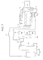
- FIG. 7 illustrates a cooling circuit for the hydraulic excavator (exemplary embodiment 1).
- FIG. 8 is a schematic rear view illustrating an engine room (exemplary embodiment 2).
- FIG. 9 is a schematic rear view illustrating an engine room (exemplary embodiment 3).
- FIG. 10 is a plan view illustrating an arrangement structure of devices (related art 1).
- FIG. 11 is a plan view illustrating an arrangement structure of devices (related art 2).
- Embodiment(s) of the invention will be described below with reference to attached drawings.
- An arrangement of a hydraulic excavator which is one type of construction machines will be exemplified below as a hybrid working vehicle according to the invention.
- the hybrid working vehicle includes not only the hydraulic excavator, but also other construction machines, civil engineering machines, agricultural machines, traveling vehicles, delivery vehicles and the like
- the invention is not limited to a shape and an arrangement structure as described below but includes other shapes and arrangement structures of the hybrid working vehicle as long as an object of the invention can be achieved.
- the invention is not limited to the following exemplary embodiments, and includes various modifications.
- a hydraulic excavator 1 includes an swingable upper swing body 3 mounted on an upper portion of a lower traveling body 2 through a swing circle 7 .
- the upper swing body 3 is swingably provided by a later-described swing motor 22 (see FIGS. 2 and 3 ).
- An upper swing body frame 6 is provided on a bottom portion of the upper swing body 3 .
- An outer cover 9 covering an engine room 35 , a counterweight 8 forming the engine room 35 with the outer cover 9 , an operation room 5 , a working machine 4 and the like are mounted on the upper swing body frame 6 .
- the outer cover 9 is directly attachable to a later-described outer frame 11 (see FIG. 5 ) through a bolt or the like.
- An engine hood 40 is provided in a portion covering the engine room 35 as a part of the outer cover 9 .
- a door 41 is openably and closably provided to check the inside of the engine room 35 in a part of the engine hood 40 .
- the engine hood 40 is provided in a portion covering the engine room 35 and formed of different components from components of the outer cover 9 in the figures, the engine hood 40 may be formed of the same components as those of the outer cover 9 .
- the outer frame 11 is provided as a frame for attaching the outer cover 9 in the figures, the outer cover 9 is also used as a member for supporting a later-described cleaning unit 18 .
- An intake hole 12 for delivering outer air into the engine room 35 includes a plurality of intake openings formed on the engine hood 40 in an upper portion of the door 41 .
- the intake hole 12 is sufficiently large for delivering the outer air into the engine room 35 .
- an exhaust hole (not shown) is provided, for example, on the engine hood 40 on a side opposing to a side at which the intake hole 12 is formed, or on the upper swing body frame 6 .
- the intake hole 12 is formed on the engine hood 40 according to the exemplary embodiment, the intake hole 12 may be formed on the door 41 .
- FIG. 2 is a schematic perspective view illustrating an arrangement structure of members in the engine room 35 , and arrangement of components for a hybrid system, and the like, which are provided on the upper swing body frame 6 .
- FIG. 3 is a schematic plan view illustrating members mounted on the upper swing body frame 6 .
- FIG. 4 is a schematic rear view illustrating an arrangement structure of the engine room 35 .
- the counterweight 8 , the engine hood 40 and the outer cover 9 are respectively shown as a two-dot chain phantom line.
- the counterweight 8 is shown as the two-dot chain phantom line.
- a flow of outer air sucked in the engine room 35 is shown as an arrow.
- wirings, pipes and the like are not shown.
- a partition 10 provided on a front side of the hydraulic excavator 1 and an end surface of an oil tank 29 stand on one side of the engine room 35 .
- a wall 8 a of the counterweight 8 stands on the other side of the engine room 35 .
- a partition member for partitioning the hybrid working vehicle into the front portion of the hybrid working vehicle and the engine room is provided by the partition 10 and the end surface of the oil tank 29 .
- the engine room 35 is divided into a left room and a right room by the cooling unit 18 as a wall of the engine.
- An intake chamber 36 is formed at a left side shown in FIG. 2 and a chamber for mounting the engine and the like are formed at a right side shown in FIG. 2 .
- An engine 15 , a generator-motor 16 and a main hydraulic pump 17 are arranged in line.
- a power unit is provided by the engine 15 , the generator-motor 16 and the main hydraulic pump 17 .
- the power unit is disposed between: the partition 10 and the end surface 29 a of the oil tank 29 ; and the wall 8 a of the counterweight 8 .
- the cooling unit 18 includes cooling devices on a hydraulic line including the engine such as an engine radiator, an oil cooler, an outer cooler, and a fuel cooler horizontally arranged in parallel, with which a radiator for cooling a later-described electronic unit is integrated.
- the intake chamber 36 is provided in front of the cooling unit 18 .
- the radiator for cooling the electronic unit and the cooling devices on the hydraulic line may be separately disposed in parallel.
- a cooling fan 19 shown as a two-dot chain line in a shroud 20 is provided in the rear of the cooling unit 18 .
- a wind tunnel 21 is connected to the shroud 20 . Cooling air sucked by the cooling fan 19 is adjusted to flow straight by the wind tunnel 21 , and intensively supplied to the power unit and the like arranged on a downstream side of the wind tunnel 21 .
- the generator-motor 16 and the main hydraulic pump 17 may be separately or parallely arranged from the engine 15 via a belt driving unit or the like.
- Cooling air discharged from the wind tunnel 21 cools the power unit including the engine 15 , the generator-motor 16 and the main hydraulic pump 17 and the like. Then, the cooling air is discharged to the outside from an exhaust hole (not shown) of the outer cover 9 , which is arranged at a right side of FIG. 2 , or an exhaust hole formed in a lower portion of the engine 15 , the generator-motor 16 , the main hydraulic pump 17 or the like.
- FIGS. 3 and 4 , and FIG. 5 that is a side view illustrating the cooling unit 18 as viewed from the intake chamber 36 , a storage 26 for storing electric power generated by the generator-motor 16 and a controller 25 for a hybrid system are arranged in a portion displaced to the outer frame 11 in the intake chamber 36 .
- the storage 26 stores electric power generated by the generator-motor 16 . Also, when a driving torque of the engine 15 and the engine 15 needs to be assisted, the storage 26 supplies electric power to a driving motor.
- the controller 25 includes controlling devices such as an inverter that converts electric power generated by the generator-motor 16 from alternating current into direct current and converts direct current stored by the storage 26 into alternating current, and a driver that controls an electric equipment for a hybrid systemd.
- controlling devices such as an inverter that converts electric power generated by the generator-motor 16 from alternating current into direct current and converts direct current stored by the storage 26 into alternating current, and a driver that controls an electric equipment for a hybrid systemd.
- the wirings, the pipes and the like are also not shown in FIG. 5 .
- a downsized high-capacity capacitor can be used as the storage 26 .
- a small high-capacity capacitor capable of repeating charge and discharge at a high speed, a lithium ion battery, a lithium polymer battery or the like may be used as the storage 26 .
- the storage 26 is mounted on a plate-shaped portion of a cooling heat sink 24 and is cooled by cooling liquid supplied in the cooling heat sink 24 so that efficiency and lifetime of the storage 26 are not lowered because the storage 26 does not need to work at high temperature. Also, to prevent the controller 25 from heat generation, a cooling passage (not shown) for the cooling liquid delivered from the cooling heat sink 24 is provided in a housing in which the controller 25 is accommodated.
- the storage 26 and the controller 25 are unitized as an electronic unit 38 .
- the cooling heat sink 24 may have a plate-like shape as a whole. However, a height position of an edge of the cooling heat sink 24 may be extended to a position substantially the same as a height position of an upper surface of a side frame 6 a of the upper swing body frame 6 , as shown in a dotted line in FIGS. 4 and 5 .
- the storage 26 is accommodated in the cooling heat sink 24 .
- the controller 25 disposed in an upper portion of the storage 26 can protrude from an upper surface of the upper swing body frame 6 . Therefore, the controller 25 can be cooled by outer air sucked in the intake chamber 36 without being blocked by the edge of the cooling heat sink 24 .
- the storage 26 can be further downsized, a flow of outer air supplied to the cooling unit 18 is not disturbed even when the electronic unit 38 is arranged in front of the cooling unit 18 .
- FIG. 6 is a perspective view illustrating a rear side of the hydraulic excavator 1 as viewed from a front side thereof.
- the counterweight 8 is attached to the upper swing body frame 6 , and the power unit, the cooling unit, the storage and the like are not shown. As shown in FIG.
- the under cover 13 is attached to the side frame 6 a included in the upper swing body frame 6 , and is arranged in a bottom portion of the upper swing body frame 6 , which is inside the side frame 6 a .
- the electronic unit 38 is arranged within a main frame 30 , the side frame 6 a , a middle frame 6 b , and a rear frame 6 c , which form the upper swing body frame 6 (see FIG. 6 ).
- the cooling heat sink 24 is elastically supported to be fixed on the under cover 13 via a buffering member 42 .
- the electronic unit 38 integrated with the cooling heat sink 24 can be less affected by a vibration from the hydraulic excavator 1 .
- Cooling liquid discharged from a cooling pump 27 disposed in the intake chamber 36 can be supplied to the cooling heat sink 24 .
- the cooling pump 27 and the electronic unit 38 may be assembled, or the cooling pump 27 may be disposed separately from the electronic unit 38 .
- FIG. 7 illustrates a cooling circuit.
- the storage 26 is cooled down by cooling liquid supplied to the cooling heat sink 24 from the cooling pump 27 .
- the controller 25 is cooled down by the cooling liquid when the cooling liquid passes through the passage provided in the housing for the controller 25 .
- cooling oil in a swing motor 22 that swings the upper swing body 3 (see FIG. 1 ) relative to the lower traveling body 2 (see FIG. 1 ).
- the swing motor 22 is driven by electric power from the storage 26 .
- the cooling liquid After the cooling liquid cools the cooling oil in the swing motor 22 , the cooling liquid is cooled by a radiator 31 disposed in the front of the cooling devices in the hydraulic line such as an engine radiator 18 a , an oil cooler 18 b , an outer cooler 18 c , a fuel cooler 18 d and the like. Then, the cooling liquid is directly sucked by the cooling pump 27 , and circulates in the above-described cooling circuit.
- the cooling liquid cooled down by the radiator 31 may be discharged into a tank (not shown), and the cooling liquid in the tank may be sucked by the cooling pump 27 .
- the radiator of the cooling devices on the hydraulic line may serve as the radiator 31 of the above-described cooling circuit.
- the cooling oil for cooling a swing motor 22 is supplied by a hydraulic pump 90 driven by the engine 15 via a PTO device, and circulates. Another hydraulic pump 91 is also driven by the engine 15 in the same manner.
- the hydraulic pump 91 is provided for supplying and circulating the cooling oil for cooling the generator-motor 16 .
- the oil cooler 16 a is provided in the generator-motor 16 and the cooling oil is cooled by an engine cooling liquid from the engine 15 in an oil cooler 16 a .
- a circuit of the cooling liquid such as a nonfreezing aqueous solution is shown in a full line and a circuit of the cooling oil is shown in a dotted line.
- a fuel tank 28 , an oil tank 29 and battery box/operating valve 37 for a vehicle having the hydraulic excavator 1 are arranged in a front and right portion of the upper swing body frame 6 .
- the air cleaner 34 and the like are disposed at a left side of the upper swing body frame 6 .
- a central portion of the counterweight 8 is mounted and fixed by fitting into the main frame 30 extending rearward from the upper swing body frame 6 while both end edge portions of the counterweight 8 are supported and fixed by the upper swing body frame 6 , the outer frame 11 and the like.
- the cooling unit 18 and the radiator 31 for controlling electronic devices can be arranged in one place.
- the flow of air introduced through the intake hole 12 caused by the cooling fan 19 disposed in the shroud 20 can be can be efficiently used. Since the intake chamber 36 is surrounded by the cooling unit 18 , the partition 10 , the end surface 29 a of the oil tank 29 , the engine hood 40 and the door 41 included in the outer cover 9 , and the wall 8 a of the counterweight 8 , cooling efficiency of the cooling unit 18 and the radiator 31 can be enhanced by effectively using outer air sucked in the intake chamber 36 .
- Cooling air that has cooled the cooling unit 18 and the radiator 31 is adjusted to straighten flow by the wind tunnel 21 connected to the shroud 20 , so that the engine 15 , the generator-motor 16 , the main hydraulic pump 17 and the like can be cooled down. Cooling air having a straight flow can be delivered evenly along surfaces of the engine 15 , the generator-motor 16 , the main hydraulic pump 17 and the like.
- the cooling of the engine 15 , the generator-motor 16 , the main hydraulic pump 17 and the like are conducted not only with the cooling air from the wind tunnel 21 , but also with cooling liquid, oil, or the like cooled by the cooling unit 18 as in a conventional method.
- the electronic unit 38 that unitizes the storage 26 and the controller 25 can be arranged in a lateral portion of the intake chamber 36 .
- a flow of air sucked in the intake chamber 36 can be supplied to the cooling unit 18 and the radiator 31 without being disturbed by the electronic unit 38 .
- the storage 26 can be arranged in the cooling heat sink 24 .
- the cooling of the storage 26 having a high-calorific power can start with cooling liquid. Accordingly, a cooling efficiency of the electronic unit 38 including the storage 26 and the controller 25 can be considerably enhanced.
- the electronic unit 38 that unitizes the storage 26 and the controller 25 , assemblability for disposing the electronic unit 38 on the upper swing body frame 6 can be enhanced. Furthermore, since the electronic unit 38 can be disposed near the generator-motor 16 , the wirings can be shortened, and electric power losses due to the wirings can be reduced.
- the cooling pump 27 for supplying cooling liquid to the electronic unit 38 and the generator-motor 22 is disposed in the intake chamber 36 through which cooling air passes, the cooling pump 27 can be cooled.
- FIG. 8 is a schematic rear view illustrating an engine room showing another exemplary embodiment according to the invention.
- the electronic unit 38 is disposed in the intake chamber 36 .
- the electronic unit 38 is disposed close to the main hydraulic pump 17 of the power unit according to the second exemplary embodiment.
- Other components according to the exemplary embodiment are arranged in the same manner as in the first exemplary embodiment.
- the same components as in the exemplary embodiment 1 are denoted by the same reference numerals, and thus detailed description thereof will be hereinafter omitted.
- the cooling heat sink 24 in which the electronic unit 38 is disposed is arranged on the under cover 13 (see FIG. 6 ) formed within the side frame 6 a of the upper swing body frame 6 in a space under the main hydraulic pump 17 .
- the electronic unit 38 is arranged in the main frame 30 , the side frame 6 a , the middle frame (not shown), the rear frame 6 c , which form the upper swing frame body 6 , according to the second exemplary embodiment.
- a height position of an upper surface of the cooling heat sink 24 is substantially the same as a height position of an upper surface of the side frame 6 a of the upper swing body frame 6 .
- the storage 26 is downwardly settled in the cooling heat sink 24 from above.
- the controller 25 which is disposed in an upper portion of the storage 26 , can be positioned to protrude from the upper surface of the upper swing body frame 6 and not to abut on the main hydraulic pump 17 .
- the cooling heat sink 24 is elastically supported to be fixed on the under cover 13 via the buffering member 42 . Cooling liquid discharged from a cooling pump (not shown) that assembles the cooling heat sink 24 and the electronic unit 38 can be supplied to the cooling heat sink 24 .
- the cooling pump may be disposed separately from the electronic unit 38 .
- the electronic unit 38 can be disposed near the generator-motor 16 , the wirings can be shortened and electric power losses due to the line can be reduced.
- the storages may be respectively disposed on a lower portion of the intake chamber 36 and a lower portion of the main hydraulic pump 17 by combining arrangements of the first exemplary embodiment and the second exemplary embodiment.
- the high-capacity capacitor may be provided as the storage 26 .
- FIG. 9 is a schematic rear view illustrating an engine room showing still another exemplary embodiment according to the invention.
- the cooling fan 19 driven by the engine 15 is disposed in the wind tunnel 21 such that a part of the cooling fan 19 (approximately 1 ⁇ 3 of the cooling fan 19 ) is exposed in a space close to the engine 15 . According to such an arrangement, cooling air can be effectively sucked and cooling efficiency in the cooling components can be enhanced.
Landscapes
- Engineering & Computer Science (AREA)
- Mining & Mineral Resources (AREA)
- Civil Engineering (AREA)
- General Engineering & Computer Science (AREA)
- Structural Engineering (AREA)
- Cooling, Air Intake And Gas Exhaust, And Fuel Tank Arrangements In Propulsion Units (AREA)
- Component Parts Of Construction Machinery (AREA)
- Hybrid Electric Vehicles (AREA)
- Operation Control Of Excavators (AREA)
Applications Claiming Priority (3)
| Application Number | Priority Date | Filing Date | Title |
|---|---|---|---|
| JP2006-211006 | 2006-08-02 | ||
| JP2006211006 | 2006-08-02 | ||
| PCT/JP2007/051481 WO2008015798A1 (fr) | 2006-08-02 | 2007-01-30 | Véhicule hybride |
Publications (2)
| Publication Number | Publication Date |
|---|---|
| US20090199553A1 US20090199553A1 (en) | 2009-08-13 |
| US8037963B2 true US8037963B2 (en) | 2011-10-18 |
Family
ID=38996984
Family Applications (1)
| Application Number | Title | Priority Date | Filing Date |
|---|---|---|---|
| US12/376,106 Active 2028-01-21 US8037963B2 (en) | 2006-08-02 | 2007-01-30 | Hybrid working vehicle |
Country Status (6)
| Country | Link |
|---|---|
| US (1) | US8037963B2 (ja) |
| EP (1) | EP2053167B1 (ja) |
| JP (2) | JP4981050B2 (ja) |
| KR (1) | KR101217581B1 (ja) |
| CN (3) | CN101501278B (ja) |
| WO (1) | WO2008015798A1 (ja) |
Cited By (18)
| Publication number | Priority date | Publication date | Assignee | Title |
|---|---|---|---|---|
| US20100025136A1 (en) * | 2007-06-26 | 2010-02-04 | Hitachi Construction Machinery Co., Ltd. | Construction machine |
| US20100038162A1 (en) * | 2007-06-26 | 2010-02-18 | Hitachi Construction Machinery Co., Ltd. | Automotive construction machine |
| US20100192551A1 (en) * | 2007-09-26 | 2010-08-05 | Kobelco Construction Machinery Co., Ltd. | Construction machine |
| US20100297926A1 (en) * | 2009-05-25 | 2010-11-25 | Kobelco Construction Machinery Co., Ltd | Hybrid working machine |
| US20110000637A1 (en) * | 2008-03-06 | 2011-01-06 | Hitachi Construction Machinery Co., Ltd. | Heat Exchanging Device for Construction Machine |
| US20120186889A1 (en) * | 2010-05-26 | 2012-07-26 | Hitachi Construction Machinery Co., Ltd. | Hybrid construction machine |
| US20120325568A1 (en) * | 2009-12-08 | 2012-12-27 | Sumitomo (S.H.I.) Construction Machinery Co., Ltd. | Construction machine |
| US20130115037A1 (en) * | 2011-06-17 | 2013-05-09 | Komatsu Ltd. | Hydraulic excavator |
| US20130133962A1 (en) * | 2011-03-31 | 2013-05-30 | Komatsu Ltd | Construction machine |
| US20140000975A1 (en) * | 2011-02-18 | 2014-01-02 | Kobelco Construction Machinery Co., Ltd. | Hybrid construction machine |
| US20140311816A1 (en) * | 2013-04-19 | 2014-10-23 | Kobelco Construction Machinery Co., Ltd. | Construction machine |
| US8875823B2 (en) * | 2012-07-13 | 2014-11-04 | Deere & Company | Multi-functional cooling system |
| US8960342B2 (en) | 2011-02-22 | 2015-02-24 | Deere & Company | Swing-out coolers and cooling fans |
| US9290906B2 (en) | 2011-01-14 | 2016-03-22 | Hitachi Construction Machinery Co., Ltd. | Construction machine |
| US9362797B2 (en) | 2011-03-31 | 2016-06-07 | Komatsu Ltd. | Generator motor and work machine |
| US10000908B2 (en) * | 2014-07-28 | 2018-06-19 | Hitachi Construction Machinery Co., Ltd. | Hybrid-type working machine |
| US10487476B2 (en) * | 2015-10-06 | 2019-11-26 | Hitachi Construction Machinery Co., Ltd. | Construction machine |
| US20220145587A1 (en) * | 2020-11-12 | 2022-05-12 | Sumitomo Construction Machinery Co., Ltd. | Excavator |
Families Citing this family (59)
| Publication number | Priority date | Publication date | Assignee | Title |
|---|---|---|---|---|
| DE112008000589B4 (de) * | 2007-03-23 | 2015-11-19 | Komatsu Ltd. | Energieerzeugungssteuerverfahren einer Hybridbaumaschine und Hybridbaumaschine |
| JP5236433B2 (ja) * | 2008-11-18 | 2013-07-17 | 住友重機械工業株式会社 | ハイブリッド型建設機械 |
| KR101482481B1 (ko) | 2008-11-18 | 2015-01-15 | 스미도모쥬기가이고교 가부시키가이샤 | 작업기계 |
| JP5312999B2 (ja) * | 2009-03-19 | 2013-10-09 | 住友重機械工業株式会社 | ハイブリッド型建設機械 |
| JP5178548B2 (ja) * | 2009-01-20 | 2013-04-10 | 住友重機械工業株式会社 | ハイブリッド型建設機械 |
| JP5613405B2 (ja) * | 2009-01-14 | 2014-10-22 | 住友重機械工業株式会社 | サーボ制御システム及び作業機械 |
| JP5318741B2 (ja) * | 2009-01-14 | 2013-10-16 | 住友重機械工業株式会社 | ハイブリッド型建設機械 |
| JP4867998B2 (ja) * | 2009-01-16 | 2012-02-01 | 株式会社豊田自動織機 | 産業車両用電気部品ユニットおよび該ユニットを有する産業車両 |
| EP2607146B1 (de) * | 2009-02-05 | 2014-11-26 | AVL List GmbH | Stromerzeugungsaggregat |
| JP5338479B2 (ja) * | 2009-05-25 | 2013-11-13 | コベルコ建機株式会社 | ハイブリッド作業機械 |
| JP5189039B2 (ja) * | 2009-07-17 | 2013-04-24 | 住友建機株式会社 | 建設機械 |
| JP5079750B2 (ja) * | 2009-07-17 | 2012-11-21 | 住友建機株式会社 | 建設機械 |
| JP5189041B2 (ja) * | 2009-07-17 | 2013-04-24 | 住友建機株式会社 | ハイブリッド型建設機械 |
| JP5445000B2 (ja) * | 2009-09-29 | 2014-03-19 | コベルコ建機株式会社 | ハイブリッド建設機械 |
| US8362629B2 (en) * | 2010-03-23 | 2013-01-29 | Bucyrus International Inc. | Energy management system for heavy equipment |
| JP5580681B2 (ja) | 2010-07-22 | 2014-08-27 | 日立建機株式会社 | 電動作業車両 |
| CN103140451B (zh) | 2010-09-30 | 2015-08-05 | 积水化学工业株式会社 | 夹层玻璃用中间膜及夹层玻璃 |
| US8549838B2 (en) | 2010-10-19 | 2013-10-08 | Cummins Inc. | System, method, and apparatus for enhancing aftertreatment regeneration in a hybrid power system |
| JP5421225B2 (ja) * | 2010-11-19 | 2014-02-19 | 株式会社小松製作所 | 作業機械、電気制御ユニット、およびインバータ |
| CN103261532B (zh) * | 2010-12-15 | 2015-06-03 | 住友重机械工业株式会社 | 挖土机 |
| US8833496B2 (en) | 2010-12-20 | 2014-09-16 | Cummins Inc. | System, method, and apparatus for battery pack thermal management |
| US8742701B2 (en) | 2010-12-20 | 2014-06-03 | Cummins Inc. | System, method, and apparatus for integrated hybrid power system thermal management |
| US8473177B2 (en) | 2010-12-31 | 2013-06-25 | Cummins, Inc. | Apparatuses, methods, and systems for thermal management of hybrid vehicle SCR aftertreatment |
| US9043060B2 (en) | 2010-12-31 | 2015-05-26 | Cummins Inc. | Methods, systems, and apparatuses for driveline load management |
| US9096207B2 (en) | 2010-12-31 | 2015-08-04 | Cummins Inc. | Hybrid vehicle powertrain cooling system |
| JP2012154092A (ja) | 2011-01-26 | 2012-08-16 | Kobelco Contstruction Machinery Ltd | ハイブリッド建設機械 |
| JP5814577B2 (ja) * | 2011-03-24 | 2015-11-17 | 株式会社小松製作所 | 電動式作業車両及びそのバッテリ保持構造 |
| JP5545766B2 (ja) * | 2011-03-30 | 2014-07-09 | 住友重機械工業株式会社 | 作業機械 |
| JP5358609B2 (ja) * | 2011-03-31 | 2013-12-04 | 株式会社小松製作所 | 発電電動機および作業機械 |
| JP5290345B2 (ja) * | 2011-03-31 | 2013-09-18 | 株式会社小松製作所 | 発電電動機および作業機械 |
| JP5706793B2 (ja) * | 2011-09-20 | 2015-04-22 | 日立建機株式会社 | 発電電動機とこれを用いた電動車両 |
| ITTO20110924A1 (it) | 2011-10-14 | 2013-04-15 | Merlo Project S R L Con Unico Socio | Macchina da lavoro ibrido elettro-idraulico |
| KR101457937B1 (ko) * | 2012-04-24 | 2014-11-07 | 이청종 | 서버용 유냉식 냉각장치 및 그 구동 방법 |
| JP5997932B2 (ja) * | 2012-05-21 | 2016-09-28 | 日立建機株式会社 | 電気式回転機械および該電気式回転機械を備えたハイブリッド式建設機械 |
| JP2013087620A (ja) * | 2012-06-20 | 2013-05-13 | Handa Kikai Kk | 道路舗装車両 |
| JP5929541B2 (ja) * | 2012-06-20 | 2016-06-08 | コベルコ建機株式会社 | 建設機械 |
| PL2728066T3 (pl) | 2012-10-30 | 2021-04-06 | Joseph Vögele AG | Maszyna budowlana z elementami składowymi maszyny |
| WO2014120930A1 (en) | 2013-01-30 | 2014-08-07 | Parker-Hannifin Corporation | Hydraulic hybrid swing drive system for excavators |
| JP5685616B2 (ja) * | 2013-03-26 | 2015-03-18 | 住友建機株式会社 | 建設機械 |
| JP5972821B2 (ja) * | 2013-03-29 | 2016-08-17 | 株式会社小松製作所 | 発電機モータへのディーゼル酸化触媒装置搭載構造 |
| US9540788B2 (en) | 2013-08-09 | 2017-01-10 | Komatsu Ltd. | Work vehicle |
| JP5707004B1 (ja) | 2013-08-09 | 2015-04-22 | 株式会社小松製作所 | 作業車両 |
| JP5867485B2 (ja) * | 2013-11-20 | 2016-02-24 | コベルコ建機株式会社 | 建設機械 |
| JP5962686B2 (ja) * | 2014-01-30 | 2016-08-03 | コベルコ建機株式会社 | 建設機械の電装品冷却構造 |
| JP6040187B2 (ja) * | 2014-02-24 | 2016-12-07 | 日立建機株式会社 | 建設機械 |
| JP6175405B2 (ja) * | 2014-05-30 | 2017-08-02 | 日立建機株式会社 | 建設機械 |
| JP6356002B2 (ja) | 2014-07-28 | 2018-07-11 | 日立建機株式会社 | ハイブリッド式作業機 |
| JP6469381B2 (ja) * | 2014-07-28 | 2019-02-13 | 日立建機株式会社 | ハイブリッド式作業機 |
| KR20170023703A (ko) | 2015-08-24 | 2017-03-06 | 가부시키가이샤 고마쓰 세이사쿠쇼 | 하이브리드 작업 차량 |
| JP6914660B2 (ja) * | 2016-01-25 | 2021-08-04 | 住友建機株式会社 | ショベル |
| JP6850753B2 (ja) * | 2018-03-13 | 2021-03-31 | ヤンマーパワーテクノロジー株式会社 | 作業車両 |
| JP6810082B2 (ja) * | 2018-03-26 | 2021-01-06 | 日立建機株式会社 | 建設機械 |
| JP6997045B2 (ja) * | 2018-07-03 | 2022-01-17 | ヤンマーパワーテクノロジー株式会社 | ハイブリッド建設機械 |
| WO2021042255A1 (en) * | 2019-09-03 | 2021-03-11 | Guangxi Liugong Machinery Co., Ltd. | Driving arrangement for construction machine |
| WO2021042256A1 (en) * | 2019-09-03 | 2021-03-11 | Guangxi Liugong Machinery Co., Ltd. | Driving arrangement for construction machine |
| JP7272944B2 (ja) * | 2019-12-25 | 2023-05-12 | 株式会社竹内製作所 | 作業用車両 |
| CN114981504A (zh) * | 2020-02-27 | 2022-08-30 | 洋马动力科技有限公司 | 作业车辆的冷却装置 |
| WO2021192165A1 (ja) * | 2020-03-26 | 2021-09-30 | 株式会社日立建機ティエラ | 電動式建設機械 |
| JP2023150995A (ja) * | 2022-03-31 | 2023-10-16 | 株式会社小松製作所 | 電動式建設機械 |
Citations (11)
| Publication number | Priority date | Publication date | Assignee | Title |
|---|---|---|---|---|
| US4422572A (en) * | 1980-12-22 | 1983-12-27 | Nissan Motor Co., Ltd. | Engine cooling water circulation system |
| US5504655A (en) * | 1994-06-10 | 1996-04-02 | Westinghouse Electric Corp. | Electric vehicle power distribution module |
| JPH08126346A (ja) | 1994-10-19 | 1996-05-17 | Hitachi Ltd | 電力変換装置 |
| US6678972B2 (en) * | 2001-02-06 | 2004-01-20 | Komatsu Ltd. | Hybrid construction equipment |
| US6745860B2 (en) * | 2000-01-12 | 2004-06-08 | Komatsu Ltd. | Engine cooling air passage for construction equipment |
| JP2004169464A (ja) | 2002-11-21 | 2004-06-17 | Komatsu Ltd | 建設機械 |
| JP2004169466A (ja) | 2002-11-21 | 2004-06-17 | Komatsu Ltd | 建設機械の機器配置構造 |
| US6820866B2 (en) * | 2001-08-10 | 2004-11-23 | Goodbar Llc | Attenuator apparatus |
| US7079379B2 (en) * | 2003-11-26 | 2006-07-18 | Honda Motor Co., Ltd. | Cooling device high voltage electrical unit for motor of vehicle, and hybrid vehicle |
| US7134518B2 (en) * | 2003-03-07 | 2006-11-14 | Kobelco Construction Machinery Co., Ltd. | Construction machine |
| US7703730B2 (en) * | 2006-10-20 | 2010-04-27 | Denso International America, Inc. | Fastenerless attachment system applied to vehicle engine cooling module components |
Family Cites Families (4)
| Publication number | Priority date | Publication date | Assignee | Title |
|---|---|---|---|---|
| US6349543B1 (en) * | 1998-06-30 | 2002-02-26 | Robert Moshe Lisniansky | Regenerative adaptive fluid motor control |
| JP4072898B2 (ja) * | 2002-11-21 | 2008-04-09 | 株式会社小松製作所 | ハイブリッド式建設機械の機器配置構造 |
| JP2005076580A (ja) * | 2003-09-02 | 2005-03-24 | Hitachi Constr Mach Co Ltd | 熱交換装置 |
| US20060001399A1 (en) * | 2004-07-02 | 2006-01-05 | Lembit Salasoo | High temperature battery system for hybrid locomotive and offhighway vehicles |
-
2007
- 2007-01-30 CN CN2007800288835A patent/CN101501278B/zh not_active Expired - Fee Related
- 2007-01-30 CN CN2012102158716A patent/CN102765318A/zh active Pending
- 2007-01-30 KR KR1020097001443A patent/KR101217581B1/ko active IP Right Grant
- 2007-01-30 CN CN201210215851.9A patent/CN102864807B/zh active Active
- 2007-01-30 EP EP07707699.0A patent/EP2053167B1/en active Active
- 2007-01-30 JP JP2008527661A patent/JP4981050B2/ja active Active
- 2007-01-30 US US12/376,106 patent/US8037963B2/en active Active
- 2007-01-30 WO PCT/JP2007/051481 patent/WO2008015798A1/ja active Application Filing
-
2011
- 2011-10-27 JP JP2011236203A patent/JP4956687B2/ja active Active
Patent Citations (11)
| Publication number | Priority date | Publication date | Assignee | Title |
|---|---|---|---|---|
| US4422572A (en) * | 1980-12-22 | 1983-12-27 | Nissan Motor Co., Ltd. | Engine cooling water circulation system |
| US5504655A (en) * | 1994-06-10 | 1996-04-02 | Westinghouse Electric Corp. | Electric vehicle power distribution module |
| JPH08126346A (ja) | 1994-10-19 | 1996-05-17 | Hitachi Ltd | 電力変換装置 |
| US6745860B2 (en) * | 2000-01-12 | 2004-06-08 | Komatsu Ltd. | Engine cooling air passage for construction equipment |
| US6678972B2 (en) * | 2001-02-06 | 2004-01-20 | Komatsu Ltd. | Hybrid construction equipment |
| US6820866B2 (en) * | 2001-08-10 | 2004-11-23 | Goodbar Llc | Attenuator apparatus |
| JP2004169464A (ja) | 2002-11-21 | 2004-06-17 | Komatsu Ltd | 建設機械 |
| JP2004169466A (ja) | 2002-11-21 | 2004-06-17 | Komatsu Ltd | 建設機械の機器配置構造 |
| US7134518B2 (en) * | 2003-03-07 | 2006-11-14 | Kobelco Construction Machinery Co., Ltd. | Construction machine |
| US7079379B2 (en) * | 2003-11-26 | 2006-07-18 | Honda Motor Co., Ltd. | Cooling device high voltage electrical unit for motor of vehicle, and hybrid vehicle |
| US7703730B2 (en) * | 2006-10-20 | 2010-04-27 | Denso International America, Inc. | Fastenerless attachment system applied to vehicle engine cooling module components |
Non-Patent Citations (2)
| Title |
|---|
| English Language International Preliminary Report on Patentability dated Apr. 16, 2009, issued in counterpart International Application No. PCT/JP2007/051481. |
| English Language International Search Report dated Mar. 6, 2007 issued in parent Appln. No. PCT/JP2007/051481. |
Cited By (28)
| Publication number | Priority date | Publication date | Assignee | Title |
|---|---|---|---|---|
| US20100025136A1 (en) * | 2007-06-26 | 2010-02-04 | Hitachi Construction Machinery Co., Ltd. | Construction machine |
| US20100038162A1 (en) * | 2007-06-26 | 2010-02-18 | Hitachi Construction Machinery Co., Ltd. | Automotive construction machine |
| US8186156B2 (en) * | 2007-06-26 | 2012-05-29 | Hitachi Construction Machinery Co., Ltd. | Automotive construction machine |
| US8215434B2 (en) * | 2007-06-26 | 2012-07-10 | Hitachi Construction Machinery Co., Ltd. | Construction machine |
| US20100192551A1 (en) * | 2007-09-26 | 2010-08-05 | Kobelco Construction Machinery Co., Ltd. | Construction machine |
| US8403099B2 (en) * | 2007-09-26 | 2013-03-26 | Kobelco Construction Machinery Co., Ltd. | Construction machine |
| US20110000637A1 (en) * | 2008-03-06 | 2011-01-06 | Hitachi Construction Machinery Co., Ltd. | Heat Exchanging Device for Construction Machine |
| US20100297926A1 (en) * | 2009-05-25 | 2010-11-25 | Kobelco Construction Machinery Co., Ltd | Hybrid working machine |
| US8662969B2 (en) * | 2009-05-25 | 2014-03-04 | Kobelco Construction Machinery Co., Ltd. | Hybrid working machine |
| US8919465B2 (en) * | 2009-12-08 | 2014-12-30 | Sumitomo (S.H.I.) Construction Machinery Co., Ltd. | Construction machine |
| US20120325568A1 (en) * | 2009-12-08 | 2012-12-27 | Sumitomo (S.H.I.) Construction Machinery Co., Ltd. | Construction machine |
| US8651219B2 (en) * | 2010-05-26 | 2014-02-18 | Hitachi Construction Machinery Co., Ltd. | Hybrid construction machine |
| US20120186889A1 (en) * | 2010-05-26 | 2012-07-26 | Hitachi Construction Machinery Co., Ltd. | Hybrid construction machine |
| US9290906B2 (en) | 2011-01-14 | 2016-03-22 | Hitachi Construction Machinery Co., Ltd. | Construction machine |
| US20140000975A1 (en) * | 2011-02-18 | 2014-01-02 | Kobelco Construction Machinery Co., Ltd. | Hybrid construction machine |
| US9103092B2 (en) * | 2011-02-18 | 2015-08-11 | Kobelco Construction Machinery Co., Ltd. | Hybrid construction machine |
| US8960342B2 (en) | 2011-02-22 | 2015-02-24 | Deere & Company | Swing-out coolers and cooling fans |
| US9362797B2 (en) | 2011-03-31 | 2016-06-07 | Komatsu Ltd. | Generator motor and work machine |
| US9045879B2 (en) * | 2011-03-31 | 2015-06-02 | Komatsu Ltd. | Construction machine |
| US20130133962A1 (en) * | 2011-03-31 | 2013-05-30 | Komatsu Ltd | Construction machine |
| US20130115037A1 (en) * | 2011-06-17 | 2013-05-09 | Komatsu Ltd. | Hydraulic excavator |
| US8640803B2 (en) * | 2011-06-17 | 2014-02-04 | Komatsu Ltd. | Hydraulic excavator |
| US8875823B2 (en) * | 2012-07-13 | 2014-11-04 | Deere & Company | Multi-functional cooling system |
| US8919488B2 (en) * | 2013-04-19 | 2014-12-30 | Kobelco Construction Machinery Co., Ltd. | Construction machine |
| US20140311816A1 (en) * | 2013-04-19 | 2014-10-23 | Kobelco Construction Machinery Co., Ltd. | Construction machine |
| US10000908B2 (en) * | 2014-07-28 | 2018-06-19 | Hitachi Construction Machinery Co., Ltd. | Hybrid-type working machine |
| US10487476B2 (en) * | 2015-10-06 | 2019-11-26 | Hitachi Construction Machinery Co., Ltd. | Construction machine |
| US20220145587A1 (en) * | 2020-11-12 | 2022-05-12 | Sumitomo Construction Machinery Co., Ltd. | Excavator |
Also Published As
| Publication number | Publication date |
|---|---|
| US20090199553A1 (en) | 2009-08-13 |
| JPWO2008015798A1 (ja) | 2009-12-17 |
| JP4981050B2 (ja) | 2012-07-18 |
| KR101217581B1 (ko) | 2013-01-02 |
| CN101501278B (zh) | 2013-01-23 |
| CN102864807B (zh) | 2014-06-25 |
| CN102864807A (zh) | 2013-01-09 |
| JP4956687B2 (ja) | 2012-06-20 |
| EP2053167A1 (en) | 2009-04-29 |
| WO2008015798A1 (fr) | 2008-02-07 |
| KR20090024285A (ko) | 2009-03-06 |
| EP2053167A4 (en) | 2016-08-24 |
| CN101501278A (zh) | 2009-08-05 |
| CN102765318A (zh) | 2012-11-07 |
| EP2053167B1 (en) | 2018-10-31 |
| JP2012041819A (ja) | 2012-03-01 |
Similar Documents
| Publication | Publication Date | Title |
|---|---|---|
| US8037963B2 (en) | Hybrid working vehicle | |
| CN102686805B (zh) | 电动式工程机械 | |
| US6922990B2 (en) | Device arrangement structure for hybrid construction equipment | |
| CN1948636B (zh) | 建筑机械 | |
| US10066358B2 (en) | Hybrid-type working machine | |
| US10000908B2 (en) | Hybrid-type working machine | |
| JP4434123B2 (ja) | ハイブリッド式建設機械 | |
| US8657048B2 (en) | Hydraulic excavator | |
| JP5421225B2 (ja) | 作業機械、電気制御ユニット、およびインバータ | |
| US10184227B2 (en) | Work machine | |
| US20170362797A1 (en) | Work machine | |
| JP2004169466A (ja) | 建設機械の機器配置構造 | |
| JP6319232B2 (ja) | エンジン搭載の電気自動車 | |
| JP2008039206A (ja) | 冷却装置 | |
| JP5685616B2 (ja) | 建設機械 | |
| JP2011020641A (ja) | 建設機械 | |
| JP2003328392A (ja) | ハイブリッド車の機器配置構造 | |
| JP2017226283A (ja) | 作業機 | |
| JP2017227001A (ja) | 作業機 | |
| JP2001193101A (ja) | 建設機械 |
Legal Events
| Date | Code | Title | Description |
|---|---|---|---|
| AS | Assignment |
Owner name: KOMATSU LTD., JAPAN Free format text: ASSIGNMENT OF ASSIGNORS INTEREST;ASSIGNORS:NISHIMURA, SATORU;HIRAKI, HIKOSABUROU;SIGNING DATES FROM 20081219 TO 20090114;REEL/FRAME:022192/0501 Owner name: KOMATSU LTD., JAPAN Free format text: ASSIGNMENT OF ASSIGNORS INTEREST;ASSIGNORS:NISHIMURA, SATORU;HIRAKI, HIKOSABUROU;REEL/FRAME:022192/0501;SIGNING DATES FROM 20081219 TO 20090114 |
|
| STCF | Information on status: patent grant |
Free format text: PATENTED CASE |
|
| FPAY | Fee payment |
Year of fee payment: 4 |
|
| MAFP | Maintenance fee payment |
Free format text: PAYMENT OF MAINTENANCE FEE, 8TH YEAR, LARGE ENTITY (ORIGINAL EVENT CODE: M1552); ENTITY STATUS OF PATENT OWNER: LARGE ENTITY Year of fee payment: 8 |
|
| MAFP | Maintenance fee payment |
Free format text: PAYMENT OF MAINTENANCE FEE, 12TH YEAR, LARGE ENTITY (ORIGINAL EVENT CODE: M1553); ENTITY STATUS OF PATENT OWNER: LARGE ENTITY Year of fee payment: 12 |