US8023202B2 - Imaging lens - Google Patents
Imaging lens Download PDFInfo
- Publication number
- US8023202B2 US8023202B2 US12/308,573 US30857307A US8023202B2 US 8023202 B2 US8023202 B2 US 8023202B2 US 30857307 A US30857307 A US 30857307A US 8023202 B2 US8023202 B2 US 8023202B2
- Authority
- US
- United States
- Prior art keywords
- lens
- object side
- image side
- side face
- type compound
- Prior art date
- Legal status (The legal status is an assumption and is not a legal conclusion. Google has not performed a legal analysis and makes no representation as to the accuracy of the status listed.)
- Expired - Fee Related, expires
Links
- 238000003384 imaging method Methods 0.000 title claims abstract description 142
- 150000001875 compounds Chemical class 0.000 claims abstract description 117
- 239000000463 material Substances 0.000 claims abstract description 101
- 229920005989 resin Polymers 0.000 claims abstract description 61
- 239000011347 resin Substances 0.000 claims abstract description 61
- 239000005304 optical glass Substances 0.000 claims abstract description 39
- 239000000853 adhesive Substances 0.000 claims description 45
- 230000001070 adhesive effect Effects 0.000 claims description 45
- 229920002050 silicone resin Polymers 0.000 claims description 32
- 230000005499 meniscus Effects 0.000 claims description 6
- 230000004075 alteration Effects 0.000 abstract description 177
- 230000003287 optical effect Effects 0.000 abstract description 71
- 238000012545 processing Methods 0.000 description 24
- 201000009310 astigmatism Diseases 0.000 description 20
- 238000010586 diagram Methods 0.000 description 19
- 239000011248 coating agent Substances 0.000 description 18
- 238000000576 coating method Methods 0.000 description 18
- 239000006059 cover glass Substances 0.000 description 15
- 238000004519 manufacturing process Methods 0.000 description 15
- 235000010724 Wisteria floribunda Nutrition 0.000 description 11
- 229920000642 polymer Polymers 0.000 description 11
- 230000003247 decreasing effect Effects 0.000 description 9
- 238000001723 curing Methods 0.000 description 8
- 239000007788 liquid Substances 0.000 description 6
- 238000013461 design Methods 0.000 description 5
- 230000014509 gene expression Effects 0.000 description 5
- 239000011521 glass Substances 0.000 description 5
- 238000000034 method Methods 0.000 description 5
- 229920001187 thermosetting polymer Polymers 0.000 description 5
- 239000002131 composite material Substances 0.000 description 4
- 229910000831 Steel Inorganic materials 0.000 description 3
- 229910000679 solder Inorganic materials 0.000 description 3
- 238000005476 soldering Methods 0.000 description 3
- 239000010959 steel Substances 0.000 description 3
- 238000003848 UV Light-Curing Methods 0.000 description 2
- 239000005388 borosilicate glass Substances 0.000 description 2
- 230000000694 effects Effects 0.000 description 2
- 238000002844 melting Methods 0.000 description 2
- 230000008018 melting Effects 0.000 description 2
- 238000001029 thermal curing Methods 0.000 description 2
- 241000511976 Hoya Species 0.000 description 1
- 230000015572 biosynthetic process Effects 0.000 description 1
- 238000001816 cooling Methods 0.000 description 1
- 238000012937 correction Methods 0.000 description 1
- 230000006866 deterioration Effects 0.000 description 1
- 230000007613 environmental effect Effects 0.000 description 1
- 229920006332 epoxy adhesive Polymers 0.000 description 1
- 230000009477 glass transition Effects 0.000 description 1
- 238000010438 heat treatment Methods 0.000 description 1
- 238000007689 inspection Methods 0.000 description 1
- 230000010354 integration Effects 0.000 description 1
- 230000031700 light absorption Effects 0.000 description 1
- 239000011159 matrix material Substances 0.000 description 1
- 238000012544 monitoring process Methods 0.000 description 1
- 239000000088 plastic resin Substances 0.000 description 1
- 230000002265 prevention Effects 0.000 description 1
- 210000001747 pupil Anatomy 0.000 description 1
- 238000004088 simulation Methods 0.000 description 1
Images


Classifications
-
- G—PHYSICS
- G02—OPTICS
- G02B—OPTICAL ELEMENTS, SYSTEMS OR APPARATUS
- G02B13/00—Optical objectives specially designed for the purposes specified below
- G02B13/001—Miniaturised objectives for electronic devices, e.g. portable telephones, webcams, PDAs, small digital cameras
- G02B13/0055—Miniaturised objectives for electronic devices, e.g. portable telephones, webcams, PDAs, small digital cameras employing a special optical element
- G02B13/006—Miniaturised objectives for electronic devices, e.g. portable telephones, webcams, PDAs, small digital cameras employing a special optical element at least one element being a compound optical element, e.g. cemented elements
-
- G—PHYSICS
- G02—OPTICS
- G02B—OPTICAL ELEMENTS, SYSTEMS OR APPARATUS
- G02B13/00—Optical objectives specially designed for the purposes specified below
- G02B13/001—Miniaturised objectives for electronic devices, e.g. portable telephones, webcams, PDAs, small digital cameras
- G02B13/0015—Miniaturised objectives for electronic devices, e.g. portable telephones, webcams, PDAs, small digital cameras characterised by the lens design
- G02B13/002—Miniaturised objectives for electronic devices, e.g. portable telephones, webcams, PDAs, small digital cameras characterised by the lens design having at least one aspherical surface
- G02B13/003—Miniaturised objectives for electronic devices, e.g. portable telephones, webcams, PDAs, small digital cameras characterised by the lens design having at least one aspherical surface having two lenses
-
- G—PHYSICS
- G02—OPTICS
- G02B—OPTICAL ELEMENTS, SYSTEMS OR APPARATUS
- G02B13/00—Optical objectives specially designed for the purposes specified below
- G02B13/001—Miniaturised objectives for electronic devices, e.g. portable telephones, webcams, PDAs, small digital cameras
- G02B13/0015—Miniaturised objectives for electronic devices, e.g. portable telephones, webcams, PDAs, small digital cameras characterised by the lens design
- G02B13/002—Miniaturised objectives for electronic devices, e.g. portable telephones, webcams, PDAs, small digital cameras characterised by the lens design having at least one aspherical surface
- G02B13/0045—Miniaturised objectives for electronic devices, e.g. portable telephones, webcams, PDAs, small digital cameras characterised by the lens design having at least one aspherical surface having five or more lenses
-
- G—PHYSICS
- G02—OPTICS
- G02B—OPTICAL ELEMENTS, SYSTEMS OR APPARATUS
- G02B7/00—Mountings, adjusting means, or light-tight connections, for optical elements
- G02B7/02—Mountings, adjusting means, or light-tight connections, for optical elements for lenses
- G02B7/028—Mountings, adjusting means, or light-tight connections, for optical elements for lenses with means for compensating for changes in temperature or for controlling the temperature; thermal stabilisation
Definitions
- the present invention relates to an imaging lens, and more particularly to an imaging lens that can be suitably mounted on a portable telephone or the like.
- Reflow processing is a method for soldering an electronic component on a printed circuit board, by placing a solder ball in advance at a location where an electronic component is connected, placing the electronic component there, heating to melt the solder ball, then cooling the solder ball down.
- a reflow step for performing reflow processing is used as a method for mounting electronic elements or such components as an imaging lens on a printed circuit board. If the reflow step is used, the mounting cost of components on a printed circuit board can be decreased, and manufacturing quality can be maintained at a predetermined level.
- a portable telephone comprising an imaging lens
- electronic components arranged at predetermined positions on a printed circuit board, but also the imaging lens itself or a socket for installing the imaging lens is disposed on the printed circuit board.
- the imaging lenses installed in portable telephones are largely made of plastic in order to decrease the manufacturing cost, and to ensure lens performance. Therefore a heat resistant socket component is used for installing an imaging lens in order to prevent thermal deformation of the imaging lens in a high temperature environment, which makes it impossible to maintain optical performance thereof.
- a heat resistant socket component for installing an imaging lens is mounted on the printed circuit board of the portable telephone, so that the imaging lens is not exposed to high temperature in the reflow step (e.g. see Patent Documents 1 to 3).
- a heat resistant socket component for installing an imaging lens makes the manufacturing steps complicated, and increases the manufacturing cost, including the cost of this heat resistant socket.
- a recent demand is that the optical performance of an imaging lens installed in a portable telephone does not deteriorate even if the portable telephone itself is placed in about a 150° C. high temperature environment, considering the case of the portable telephone being left in an automobile which temporarily becomes a high temperature environment.
- a conventional imaging lens made of plastic material cannot meet this demand.
- an imaging lens installed in a portable telephone or the like must satisfy the following conditions related to optical characteristics.
- One condition is that the optical length is short.
- the optical length refers to a distance from an entrance plane at an object side to an image formation plane (also called “imaging plane”) of the imaging lens.
- imaging plane also called “imaging plane”
- this optical length must at least be shorter than the thickness of the portable telephone unit.
- a back focus which is defined as a distance from the outgoing plane at the image side to the imaging plane of the imaging lens, should be as long as possible.
- the ratio of the back focus to the focal distance must be maximized. This is because such components as a filter and a cover glass must be inserted between the imaging lens and the imaging plane.
- the imaging lens In addition to this, it is naturally demanded for the imaging lens that various aberrations are corrected to be small enough that the distortion of the image is not visually recognized, and that the integration density of the image sensing elements in minimal units (also called “pixels”), which are arranged in a matrix on the light receiving plane of a CCD (Charge Coupled Device) image sensor or the like, is sufficiently satisfied. In other words, various aberrations of the imaging lens must be well corrected.
- an image, of which various aberrations are well corrected may be called a “good image”.
- Patent Document 1 Japanese Patent Application Laid-Open No. 2006-121079 (U.S. Pat. No. 3,799,615)
- Patent Document 2 Japanese Patent Application Laid-Open No. 2004-328474 (U.S. Pat. No. 3,915,733)
- Patent Document 3 Japanese Patent Application Laid-Open No. 2004-063787 (U.S. Pat. No. 3,755,149)
- Patent Document 4 Japanese Patent Application Laid-Open No. 2005-067999
- an object of the present invention to provide an imaging lens suitable for being installed in a portable telephone or the like, and of which heat resistance is guaranteed and optical performance does not deteriorate even in a high temperature environment of a reflow step, or even if the imaging lens is installed in a portable telephone or the like and is temporarily placed in the maximum temperature environment in the design specifications.
- an imaging lens of this invention comprises a first diaphragm, a first junction type compound lens, a second diaphragm and a second junction type compound lens, characterized in that the first diaphragm, the first junction type compound lens, the second diaphragm and the second junction type compound lens are arranged in this sequence from an object side to an image side.
- the first junction type compound lens comprises a first lens, a second lens and a third lens arranged in this sequence from the object side to the image side, and the first lens and the third lens are formed of curable resin material.
- the second junction type compound lens comprises a fourth lens, a fifth lens and a sixth lens arranged in this sequence from the object side to the image side, and the fourth lens and the sixth lens are formed of a curable resin material.
- the second lens and the fifth lens are formed of a high softening temperature optical glass material.
- the first lens and the second lens are indirectly bonded, and the second lens and the third lens are indirectly bonded.
- the fourth lens and the fifth lens are indirectly bonded, and the fifth lens and the sixth lens are indirectly bonded.
- the first junction type compound lens comprises a first lens, a second lens and a third lens arranged in this sequence from the object side to the image side, and the first lens, the second lens and the third lens are formed of a curable resin material.
- the second type compound lens comprises a fourth lens, a fifth lens and a sixth lens arranged in this sequence from the object side to the image side, and the fourth lens, the fifth lens and the sixth lens are formed of a curable resin material.
- the first lens and the second lens are directly bonded or indirectly bonded, and the second lens and the third lens are directly bonded or indirectly bonded.
- the fourth lens and the fifth lens are directly bonded or indirectly bonded, and the fifth lens and the sixth lens are directly bonded or indirectly bonded.
- the curable resin material refers to both a thermosetting resin material and a UV-curable resin material.
- the high softening temperature optical glass material refers to such optical glass material as a high softening temperature mold glass material or boro-silicate glass.
- the bonding of the second lens formed of a curable resin material and the first lens or the third lens formed of a curable resin material, and the bonding of the fifth lens formed of a curable resin material and the fourth lens or the sixth lens formed of a curable resin material, are implemented as follows.
- a liquid type curable resin material is contacted to the second lens formed of the curable resin material, and the first lens or the third lens is bonded to the second lens by solidifying, that is, by curing this curable resin material.
- a liquid type curable resin material is contacted to the fifth lens formed of the curable resin material, and the fourth lens or the sixth lens is bonded to the fifth lens by solidifying, that is, by curing, this curable resin material.
- the second lens and the first lens or the third lens may be bonded by using an adhesive between the second lens and the first lens or the third lens.
- the fifth lens and the fourth lens or the sixth lens may be bonded by using an adhesive between the fifth lens and the fourth lens or the sixth lens. This bonding may be called “indirect bonding” herein below.
- the bonding of the second lens formed of a high softening temperature optical glass and the first lens or the third lens formed of a curable resin material, and the bonding of the fifth lens formed of a high softening temperature optical glass and the fourth lens or the sixth lens formed of a curable resin material, are performed by indirect bonding.
- the reflection in the interface between the second lens and the first lens or the third lens can be decreased if the adhesive is selected so that the optical characteristics of the adhesive can be utilized, such as selecting an appropriate refractive index of the adhesive with respect to the refractive index of the second lens and the refractive index of the first or third lens.
- the reflection in the interface between the fifth lens and the fourth lens or the sixth lens can be decreased if the adhesive is selected so that the optical characteristics of the adhesive can be utilized, such as selecting an appropriate refractive index of the adhesive with respect to the refractive index of the fifth lens and the refractive index of the fourth or sixth lens.
- the second lens and the fifth lens can be optical-parallel plates.
- An optical-parallel plate normally is not referred to as a lens, but in the description of the present invention, an optical-parallel plate may be included in a lens description for the convenience of explanation, regarding this as a special case where the radius of curvature of the lens surface is infinite.
- the first lens can be a plano-convex lens where the object side face of the first lens is a convex surface facing the object side on a paraxial line
- the third lens can be a plano-concave lens where the image side face of the third lens is a concave surface facing the image side on a paraxial line
- the fourth lens is a plano-convex lens where the object side face of the fourth lens is a convex surface facing the object side on a paraxial line
- the sixth lens can be a plano-concave lens where the image side face of the sixth lens is a concave surface facing the image side on a paraxial line.
- the second lens is a biconvex lens
- the first lens can be a lens where the object side face of the first lens is a convex surface facing the object side on a paraxial line
- the third lens is a lens where the image side face of the third lens is a concave surface facing the image side on a paraxial line
- the fifth lens is a biconcave lens
- the fourth lens is a lens where the object side face of the fourth lens is a convex surface facing the object side on a paraxial line
- the sixth lens is a lens where the image side face of the sixth lens is a concave surface facing the image side on a paraxial line.
- the second lens is a meniscus lens of which convex surface faces the object side
- the first lens is a lens where the object side face of the first lens is a convex surface facing the object side on a paraxial line
- the third lens is a lens where the image side face of the third lens is a concave surface facing the image side on a paraxial line
- the fifth lens is a meniscus lens of which convex surface faces the object side
- the fourth lens is a lens where the object side face of the fourth lens is a convex surface facing the object side on a paraxial line
- the sixth lens is a lens where the image side face of the sixth lens is a concave surface facing the image side on a paraxial line.
- the second lens is a biconcave lens
- the first lens is a lens where the object side face of the first lens is a convex surface facing the object side on a paraxial line
- the third lens is a lens where the image side face of the third lens is a concave surface facing the image side on a paraxial line
- the fifth lens is a biconvex lens
- the fourth lens is a lens where the object side face of the fourth lens is a convex surface facing the object side on a paraxial line
- the sixth lens is a lens where the image side face of the sixth lens is a concave surface facing the image side on a paraxial line.
- the object side face of the first lens and the image side face of the third lens are aspheric, and the object side face of the fourth lens and the image side face of the sixth lens are aspheric.
- the curable resin material which is a material of the first lens, third lens, fourth lens and sixth lens, is a transparent curable silicone resin.
- this curable resin material is also a transparent curable silicone resin. “Transparent” here indicates that the light absorption of visible light is small (transparent) enough to have no influence on practical use.
- the imaging lens of the present invention in the first junction type compound lens constituting this imaging lens, the first and the third lenses, which are formed of curable resin material, sandwich and are indirectly bonded to the second lens, which is formed of a high softening temperature optical glass material.
- the fourth and the sixth lenses which are formed of curable resin material, sandwich and are indirectly bonded to the fifth lens, which is formed of a high softening temperature optical glass material.
- the high softening temperature optical glass material here refers to an optical glass material of which softening temperature is higher than both the temperature in the reflow processing and the maximum environmental temperature in the design specifications of the junction type compound lens.
- the phrase “high softening temperature optical glass material” is used when a thermal characteristic of the optical glass material is discussed, and the simple phrase “optical glass” may be used when an optical characteristic is discussed.
- the first junction type compound lens comprises a first lens, a second lens and a third lens arranged in this sequence from the object side to the image side, and the first lens, the second lens and the third lens are formed of a curable resin material.
- the second junction type compound lens comprises a fourth lens, a fifth lens and a sixth lens arranged in this sequence from the object side to the image side, and the fourth lens, the fifth lens and the sixth lens are formed of a curable resin material.
- the first lens and the second lens are directly bonded or indirectly bonded, and the second lens and the third lens are directly bonded or indirectly bonded.
- the fourth lens and the fifth lens are directly bonded or indirectly bonded, and the fifth lens and the sixth lens are directly bonded or indirectly bonded.
- the curable resin material does not soften once curing processing is performed, even if the temperature rises more than a predetermined temperature.
- This nature of the curable resin material is different from the nature of a plastic resin material, such as plastic material, which becomes soft and plasticized if the material is exposed to a temperature that exceeds a predetermined temperature, which is referred to as a “softening temperature” (also referred to as a “glass transition temperature”).
- a softening temperature also referred to as a “glass transition temperature”.
- the second lens and the fifth lens are also formed of a high softening temperature optical glass material, so the optical performance thereof does not deteriorate even under a high temperature environment.
- High temperature environment here refers to a temperature environment higher than both the temperature in reflow processing and the maximum temperature in the design specifications of the junction type compound lens.
- the optical performance of the first junction type compound lens and the second junction type compound lens is guaranteed even in a high temperature environment, where the temperature is at the maximum, which is assumed in reflow processing and when the imaging lens is in use.
- the manufacturing accuracy of the thickness of the second lens and fifth lens is high.
- the manufacturing accuracy of the thickness of the second lens and fifth lens in the case of using a high softening temperature optical glass material is about ⁇ 10 ⁇ m, while the manufacturing accuracy of the thickness thereof in the case of using curable resin material can be improved up to about ⁇ 3 ⁇ m.
- the imaging lens can be manufactured without deviating very much from various characteristics, such as aberration, that are assumed in design specifications.
- an adhesive is used between the bonding surfaces.
- the first lens to the third lens are formed first, then an adhesive is coated on a surface of the second lens facing the first lens or the third lens, or on the surface of the first lens or the third lens facing the second lens, and both lenses are contacted.
- the fourth lens to the sixth lens are formed first, then an adhesive is coated on a surface of the fifth lens facing the fourth lens or sixth lens, or on the surface of the fourth lens or sixth lens facing the fifth lens, and both lenses are contacted.
- Coating processing may be performed on a surface of the second lens facing the first lens or the third lens, and both lenses are indirectly bonded.
- coating processing may be performed on a surface of the fifth lens facing the fourth lens or sixth lens, and both lenses are indirectly bonded.
- reflection in the interface between the second lens and the first lens or the third lens can be decreased if the adhesive is selected so that the optical characteristics of the adhesive can be utilized, such as selecting an appropriate refractive index of the adhesive with respect to the refractive index of the optical glass and the refractive index of the curable resin material. If the coating processing is performed on the surface of the second lens facing the first lens or the third lens, and these lenses are bonded, as mentioned above, the reflection in the interface with the first lens (or the third lens) can be decreased. In the same manner, reflection in the interface between the fifth lens and the fourth lens or the sixth lens can be decreased. Furthermore, if the coating processing is performed on the surface of the fifth lens facing the fourth lens or the sixth lens, and these lenses are bonded, as mentioned above, the reflection in the interface with the fourth lens (or the sixth lens) can be decreased.
- the optical structural principle of the imaging lens of the present invention implements two roles, which are aberration correction and image format, by a single junction type compound lens, of which optical characteristics, such as the reflective index, are as uniform as possible.
- the respective refractive index and the Abbe number of the first to third lenses, constituting the first junction type compound lens of the imaging lens of the present invention do not differ very much from each other.
- the respective refractive index and the Abbe number of the fourth to sixth lenses, constituting the second junction type compound lens do not differ very much from each other. This means that it is ideal that the respective refractive index and the Abbe number of the first to third lenses are the same as each other.
- the inventor of the present invention checked, through various simulations and prototyping, the approximate upper limit of the differences of the refractive indexes and Abbe numbers between the optical glass material and the curable resin material constituting the first and second junction type compound lenses respectively, which could generate good images. As a result, it was confirmed that an imaging lens which can generate good images can be constructed by satisfying the above Conditions (1) to (8).
- the difference between the refractive index N 2 of the first lens and the refractive index N 3 of second lens, the difference between the refractive index N 3 of the second lens and the refractive index N 4 of the third lens, the difference between the refractive index N 8 of the fourth lens and the refractive index N 9 of the fifth lens, and the difference between the refractive index N 9 of the fifth lens and the refractive index N 10 of the sixth lens are within 0.1 respectively, then the distortion aberration, astigmatism aberration and chromatic/spherical aberration become small enough to generate good images.
- the value of the chromatic aberration can be small enough to generate good images, and the images can have sufficient contrast.
- an imaging lens of which optical length is short enough to be installed in a portable telephone or the like, of which back focus is long enough to insert such components as a filter and cover glass between the imaging lens and the imaging plane, and with which good images can be acquired can be implemented.
- FIG. 1 is a cross-sectional view depicting an imaging lens according to the present invention
- FIG. 2 is a cross-sectional view depicting an imaging lens according to Embodiment 1;
- FIG. 3 is a diagram depicting the distortion aberration of the imaging lens of Embodiment 1;
- FIG. 4 is a diagram depicting the astigmatism aberration of the imaging lens of Embodiment 1;
- FIG. 5 is a diagram depicting the chromatic/spherical aberration of the imaging lens of Embodiment 1;
- FIG. 6 is a cross-sectional view depicting an imaging lens according to Embodiment 2.
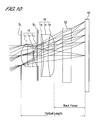
- FIG. 7 is a diagram depicting the distortion aberration of the imaging lens of Embodiment 2.
- FIG. 8 is a diagram depicting the astigmatism aberration of the imaging lens of Embodiment 2;
- FIG. 9 is a diagram depicting the chromatic/spherical aberration of the imaging lens of Embodiment 2;
- FIG. 10 is a cross-sectional view depicting an imaging lens according to Embodiment 3.
- FIG. 11 is a diagram depicting the distortion aberration of the imaging lens of Embodiment 3.
- FIG. 12 is a diagram depicting the astigmatism aberration of the imaging lens of Embodiment 3.
- FIG. 13 is a diagram depicting the chromatic/spherical aberration of the imaging lens of Embodiment 3;
- FIG. 14 is a cross-sectional view depicting an imaging lens according to Embodiment 4.
- FIG. 15 is a diagram depicting the distortion aberration of the imaging lens of Embodiment 4.
- FIG. 16 is a diagram depicting the astigmatism aberration of the imaging lens of Embodiment 4.
- FIG. 17 is a diagram depicting the chromatic/spherical aberration of the imaging lens of Embodiment 4.
- FIG. 18 is a cross-sectional view depicting an imaging lens according to Embodiment 5.
- FIG. 19 is a diagram depicting the distortion aberration of the imaging lens of Embodiment 5.
- FIG. 20 is a diagram depicting the astigmatism aberration of the imaging lens of Embodiment 5;
- FIG. 21 is a diagram depicting the chromatic/spherical aberration of the imaging lens of Embodiment 5;
- FIG. 22 is a cross-sectional view depicting an imaging lens according to Embodiment 6;
- FIG. 23 is a diagram depicting the distortion aberration of the imaging lens of Embodiment 6;
- FIG. 24 is a diagram depicting the astigmatism aberration of the imaging lens of Embodiment 6.
- FIG. 25 is a diagram depicting the chromatic/spherical aberration of the imaging lens of Embodiment 6.
- FIG. 1 is a diagram depicting a configuration of an imaging lens of an embodiment of the present invention.
- FIG. 1 shows, a first, second and third lenses constituting a first junction type compound lens 14 are denoted with L 1 , L 2 and L 3 respectively. And a fourth, fifth and sixth lenses constituting a second junction type compound lens 16 are denoted with L 4 , L 5 and L 6 respectively.
- a first diaphragm S 1 disposed on a front face (front face r 2 of the first lens) of the first junction type compound lens 14 plays a role of an aperture diaphragm and defines a position of an entrance pupil.
- a second diaphragm S 2 disposed between the first junction type compound lens 14 and the second junction type compound lens 16 plays a role of preventing a flare, which is a phenomena of a lowered image contrast, or a smear, which is a phenomena of an image smearing.
- adhesives 50 , 52 , 54 and 56 for indirect bonding, exist on the interfaces indicated by r 3 , r 4 , r 9 and r 10 respectively. If coating processing has been performed on both sides or on one side of the second lens L 2 , the coating film 60 or coating film 62 exists. If coating processing has been performed on both sides or on one side of the fifth lens L 5 , the coating film 64 or coating film 66 exists.
- an adhesive or coating film exists on the interfaces indicated by r 3 , r 4 , r 9 and r 10 , in the case of indirect bonding, but are shown as thin lines, just like r 2 , r 5 , r 8 and r 11 , and indications for the adhesives 50 , 52 , 54 and 56 and coating films 60 , 62 , 64 and 66 are omitted, so that the drawings do not become complicated.
- the thickness of the adhesive is small enough not to affect the optical characteristics of the imaging lens, so the thickness of the adhesive is ignored even if the adhesive exists on the interfaces indicated by r 3 , r 4 , r 9 and r 10 .
- the bonding surfaces of the first and third lenses L 1 and L 3 , to be directly or indirectly bonded to the second lens L 2 have a shape matching the bonding surface of the second lens L 2
- the bonding surfaces of the fourth and sixth lenses L 4 and L 6 , to be directly or indirectly bonded to the fifth lens L 5 have a shape matching the bonding surface of the fifth lens L 5 .
- the suffix i is added corresponding to the diaphragms (first and second diaphragms), and surface number of each lens, thickness of the lens, or the surface spacing of the lens sequentially from the object side to the image side.
- r i is a radius of curvature on the optical axis on the i-th surface
- d i is a distance from the i-th surface to the (i+1)th surface
- N i is a refractive index of the material of the lens having the i-th surface and (i+1)th surface
- v i is an Abbe number of the material of the lens having the i-th surface and (i+1)th surface.
- FIG. 1 the aperture of the diaphragm (first and second diaphragms) is shown by a segment. This is because the intersection of the diaphragm surface and the optical axis must be clearly shown to define the distance from the lens surface to the diaphragm surface.
- FIG. 2 , FIG. 6 , FIG. 10 , FIG. 14 , FIG. 18 and FIG. 22 which are cross-sectional views of the imaging lens of Embodiment 1 to Embodiment 6 respectively, a main body of the diaphragm for shielding light is shown by the half lines of which start point is the edge of the aperture, by opening the aperture of the diaphragm, which is opposite to FIG. 1 .
- the thickness is indicated as d 6 .
- the optical length L is a distance from the first diaphragm S 1 to the imaging plane.
- the back focus bf is a distance from the image side surface of the sixth lens L 6 constituting the second junction type compound lens 16 , to the imaging plane.
- the length from the image side face of the sixth lens L 6 to the imaging plane, which is measured without a cover glass, is regarded as the back focus bf.
- the aspherical data is shown in Table 1 to Table 6 respectively with surface numbers.
- Both surfaces (r 3 and r 4 ) when the second lens is an optical-parallel plate, both surface (r 9 and r 10 ) when the fifth lens is an optical-parallel plate, the first diaphragm S (r 1 ), second diaphragm (r 6 , r 7 ) and the surfaces of the cover glass (or filter) (r 12 and r 13 ) are planes, so the radius of the curvature is indicated as ⁇ .
- the numeric value to indicate an aspherical surface coefficient is denoted by an exponent, “e ⁇ 1” for example, which means “the ⁇ 1th power of 10”.
- the value indicated as the focal distance f is a composite focal distance of the first junction type compound lens and the second junction type compound lens.
- the open F number also called the “open F value”
- the open F number refers to the F number when the diameter of the aperture diaphragm (first diaphragm) is the maximum in design specifications.
- the diagonal length 2 Y of the square image surface is indicated as the image height. Y is a value half the diagonal length of the square image surface.
- Embodiment 1 to Embodiment 6 of the present invention will be described with reference to FIG. 2 to FIG. 25 .
- the distortion aberration curves shown in FIG. 3 , FIG. 7 , FIG. 11 , FIG. 15 , FIG. 19 and FIG. 23 show the aberration (unsatisfactory quantity of the tangent condition is shown in the abscissa by percentage) with respect to the distance from the optical axis (shown in the ordinate by percentage with the maximum distance from the optical axis within the image surface as 100).
- the chromatic/spherical aberration curve in FIG. 5 , FIG. 9 , FIG. 13 , FIG. 17 , FIG. 21 and FIG. 25 show the aberration (mm units) in the abscissa with respect to the entrance height h in the ordinate.
- the aberration values with respect to the C-line (light of which wavelength is 656.3 nm), d-line (light of which wavelength is 587.6 nm), e-line (light of which wavelength is 546.1 nm), F-line (light of which wavelength is 486.1 nm) and g-line (light of which wavelength is 435.8 nm) are shown.
- Table 1 to Table 6 show the list of the radius of curvature (mm units), lens surface spacing (mm units), refractive index of lens material, Abbe number of lens material, focal distance, F number and aspherical surface coefficient of composing lenses of Embodiment 1 to Embodiment 6 respectively.
- the radius of curvature on the optical axis and the lens surface spacing of the composing lens are shown as values when the value of the composite focal distance f of the imaging lens is normalized to 1.00 mm.
- a transparent curable silicone resin which is a curable resin material, is used for the material of the first lens L 1 and the third lens L 3 constituting the first junction type compound lens 14 , and for the material of the fourth lens L 4 and the sixth lens L 6 constituting the second junction type compound lens 16 .
- optical glass BK7 which is a high softening temperature optical glass material, is used for the material of the second lens L 2 and the fifth lens L 5 .
- BK7 is a name assigned by Schott Glass Co. to a group of borosilicate glass.
- Optical glass BK7 is now manufactured by a plurality of glass manufacturers. The refractive index and the Abbe number of commercially available optical glass BK7 are somewhat different depending on the manufacturer and the manufacturing lot.
- thermosetting silicone resin Silplus MHD made by Nippon Steel Chemical Co., Ltd., which is a curable resin material, is used for the materials of the second lens L 2 and the fifth lens L 5 .
- the transparent curable silicone resin refers to a silicone resin which is transparent to visible lights and with which the geometric shape of a lens does not change, and optical performance does not deteriorate even if the environment temporarily becomes about a 150° C. high temperature.
- the transparent curable silicone resin mentioned here can be selected from silicone resins commercialized under the name “transparent high hardness silicone resin” by silicone resin suppliers, for example.
- the first lens L 1 and the second lens L 2 are indirectly bonded, the second lens L 2 and the third lens L 3 are indirectly bonded.
- the fourth lens L 4 and the fifth lens L 5 are indirectly bonded, and the fifth lens L 5 and the sixth lens L 6 are indirectly bonded.
- the first lens L 1 and the second lens L 2 are directly bonded or indirectly bonded, and the second lens L 2 and the third lens L 3 are directly bonded or indirectly bonded.
- the fourth lens L 4 and the fifth lens L 5 are directly bonded or indirectly bonded, and the fifth lens L 5 and the sixth lens L 6 are directly bonded or indirectly bonded.
- SMX-7852 made by Fuji Polymer Industries Co., Ltd.
- SR-7010 made by Dow Corning Toray Co., Ltd.
- the refractive indexes and the Abbe numbers of these thermosetting silicone resins differ depending on the manufacturer and also differ somewhat even if the product name is the same.
- a refractive index of a lens material is a value with respect to the d-line (light of which wavelength is 587.6 nm).
- Epoxy adhesive can be used for an adhesive for indirect bonding.
- a refractive index matching type optical adhesive e.g. see ⁇ URL:http://keytech.ntt-at.co.jp/optic2/prd — 1001.html> of NTT Advanced Technology Co. [searched on May 7, 2007]
- This refractive index matching type optical adhesive has durability under heat, and even if the lens is temporarily placed in a high temperature environment, a form change, such as melting, does not occur, and the optical performance does not deteriorate.
- This refractive index matching type optical adhesive is transparent to visible lights, and the refractive index thereof can be adjusted in the range of 1.33 to 1.70 at a ⁇ 0.005 accuracy.
- this refractive index matching type optical adhesive can be manufactured with controlling the refractive index thereof to be a value close to all the refractive indexes of the first to sixth lenses.
- the adhesive to be used for indirect bonding is not limited to the above mentioned example of the refractive index matching type optical adhesive, but can be any adhesive which is transparent and which satisfies the conditions of the refractive index and heat resistance.
- a condition for the refractive index of the adhesive is that the refractive index of the adhesive is close to the refractive indexes of the two lenses to be bonded.
- a condition for the heat resistance is that even if the adhesive, which is solidified and is in a status of bonding the two lenses, is placed in a high temperature environment in the reflow step or is placed in an environment which temporarily becomes high temperature, a form change, such as melting, does not occur, and optical performance thereof does not change.
- the imaging lens of the present invention comprises a first diaphragm S 1 , a first junction type compound lens 14 , a second step S 2 and a second junction type compound lens 16 , where the first diaphragm S 1 , the first junction type compound lens 14 , the second diaphragm S 2 and the second junction type compound lens 16 are arranged in this sequence from the object side to the image side.
- the first junction type compound lens 14 comprises a first lens L 1 , a second lens L 2 and a third lens L 3 , which are arranged in this sequence from the object side to the image side.
- the second junction type compound lens 16 comprises a fourth lens L 4 , a fifth lens L 5 and a sixth lens L 6 , which are arranged in this sequence from the object side to the image side.
- a cover glass 12 is inserted between the second junction type compound lens 16 and the image sensing element 10 .
- a material of the cover glass is optical glass BK7 (made by Hoya Corporation) of which refractive index is 1.51680 and the Abbe number is 61.0.
- the composite focal distance by the first junction type compound lens and the second junction type compound lens is normalized to 1.0 mm.
- the object side face of the first lens L 1 and the image side face of the third lens L 3 constituting the first junction type compound lens 14 are aspherical, and the object side face of the fourth lens L 4 and the image side face of the sixth lens L 6 constituting the second junction type compound lens 16 are aspherical.
- the junction type compound lenses used in Embodiment 1 to Embodiment 5 are manufactured by indirectly bonding lenses. This indirect bonding is implemented by using an adhesive between lenses. Since this procedure is the same for both the first junction type compound lens and the second junction type compound lens, the first junction type compound lens will be described here as an example.
- the first to the third lenses L 1 to L 3 are formed first, then adhesive is coated on the surface of the second lens L 2 facing the first lens L 1 or the third lens L 3 , or on the surface of the first lens L 1 or the third lens L 3 , facing the second lens L 2 , and both lenses are contacted.
- Coating could be performed at least on one surface of the second lens L 2 facing the first lens L 1 or the third lens L 3 , then both lenses are bonded.
- indirect bonding or direct bonding mentioned below, could be performed after the coating processing.
- the junction type compound lens used for Embodiment 6 is manufactured by directly bonding or indirectly bonding lenses.
- junction type compound lens by direct bonding
- the following steps are performed (for details, see U.S. Pat. No. 3,926,380).
- the procedure is the same for the first junction type compound lens and the second junction type compound lens, so the first junction type compound lens will be described here as an example.
- a die for forming the first lens L 1 , that can be bonded to the second lens L 2 is prepared.
- This die is a cylinder where the side wall of the inner face is cylindrical, and the bottom face is a curved shape, the same as the object side face of the first lens L 1 .
- a transparent curable silicone resin, which is in a liquid state before curing, is injected into the die, and thermo-curing processing or UV curing processing is performed to form the first lens L 1 , and the first lens L 1 is bonded to the second lens L 2 .
- a die for forming the third lens L 3 which is bonded to the above compound lens where the first lens L 1 and the second lens L 2 are bonded, is prepared.
- the bottom face of this die has a shape the same as the image face of the third lens L 3 .
- a transparent curable silicone resin which is in a liquid state before curing, is injected into the die, thermo-curing processing or UV curing processing is performed to form the third lens L 3 , and the third lens L 3 is bonded to the second lens L 2 , where the first lens L 1 is bonded.
- the junction type compound lens is formed.
- the manufacturing device for the junction type compound lens is designed so that ultraviolet can be irradiated onto the UV-curable resin from an area above the die.
- the first lens L 1 and the third lens L 3 of the first junction type compound lens are formed of transparent curable silicone resin SMX-7852 (made by Fuji Polymer Industries Co., Ltd.), and the second lens L 2 is formed of optical glass BK7 (made by Ohara Inc.).
- the fourth lens L 4 and the sixth lens L 6 of the second junction type compound lens are formed of a transparent curable silicone resin SMX-7852 (made by Fuji Polymer Industries Co., Ltd.), and the fifth lens L 5 is formed of optical glass BK7 (made by Ohara Inc.).
- the Conditions (1), (2), (5) and (6) refer to conditions given by Expressions (1), (2), (5) and (6) respectively.
- the Conditions (3), (4), (7) and (8) refer to Conditions given by Expressions (3), (4), (7) and (8) respectively.
- ⁇ 0.1 (1) 0 ⁇
- the Conditions (1) to (8) refer to the conditions given by Expressions (1) to (8) respectively, which is the same for the description herein below (description on Embodiment 2 to Embodiment 6).
- FIG. 2 is a cross-sectional view of the imaging lens of Embodiment 1.
- the first diaphragm S 1 to play a role of an aperture diaphragm is formed at a position of an intersection of the first surface (surface at the object side) of the first lens L 1 constituting the first junction type compound lens 14 and the optical axis.
- the second diaphragm S 2 to play a role of preventing a flare or smear is formed between the first junction type compound lens 14 and the second junction type compound lens 16 .
- the F number Fno is 2.9.
- the second lens L 2 is an optical-parallel plate
- the fifth lens L 5 is an optical-parallel plate
- r 2 is a positive value and r 5 is a positive value
- the first lens L 1 is a plano-convex lens where the object side face of this first lens L 1 is a convex surface facing the object side on a paraxial line
- the third lens L 3 is a plano-concave lens where the image side face of this third lens L 3 is a concave surface facing the image side on a paraxial line.
- r 8 is a positive value and r 11 is also a positive value, so the fourth lens L 4 is a plano-convex lens where the object side face of this fourth lens L 4 is a convex surface facing the object side on a paraxial line, and the sixth lens L 6 is a plano-concave lens where the image side face of this sixth lens L 6 is a concave surface facing the image side on a paraxial line.
- FIG. 3 shows a graph of the distortion aberration curve 1 - 1
- FIG. 4 shows a graph of the astigmatism aberration curve (aberration curve 1 - 2 on the meridional surface and aberration curve 1 - 3 on the sagittal surface)
- FIG. 5 shows a graph of a chromatic/spherical aberration curve (aberration curve 1 - 4 on g-line, aberration curve 1 - 5 on F-line, aberration curve 1 - 6 on e-line, aberration curve 1 - 7 on d-line and aberration curve 1 - 8 on C-line).
- the ordinates of the aberration curves in FIG. 3 and FIG. 4 show the image height by a % of the distance from the optical axis. In FIG. 3 and FIG. 4 , 100% corresponds to 0.623 mm.
- the ordinate of the aberration curve in FIG. 5 shows the entrance height h (F number), and the maximum thereof corresponds to 2.9.
- the abscissa of FIG. 3 shows the aberration (%), and the abscissa of FIG. 4 and FIG. 5 show the value of the aberration (mm).
- the absolute value of the aberration is 2.5%, which is the maximum, at the position of 75% image height (image height: 0.467 mm), and the absolute value of the aberration is within 2.5% in a range where the image height is 0.623 mm or less.
- the absolute value of the aberration on the meridional surface is 0.029 mm, which is the maximum, at the position of 80% image height (image height: 0.498 mm), and the absolute value of the aberration is within 0.029 mm in a range where the image height is 0.623 mm or less.
- the absolute value of the aberration curve 1 - 4 on the g-line is 0.0225 mm, which is the maximum at the 100% entrance height h, and the absolute value of the aberration is within 0.0225 mm.
- the optical length can be short enough to be installed in a portable telephone or the like, the back focus can be long enough to insert such components as a filter and cover glass between the imaging lens and the imaging plane, and good images can be acquired.
- the first lens L 1 and the third lens L 3 of the first junction type compound lens are formed of transparent curable silicone resin SR-7010 (Dow Corning Toray Co., Ltd.), and the second lens L 2 is formed of optical glass BK7 (made by Ohara Inc.).
- the fourth lens L 4 and the sixth lens L 6 of the second junction type compound lens are formed of transparent curable silicone resin SR-7010 (Dow Corning Toray Co., Ltd.), and the fifth lens L 5 is formed of optical glass BK7 (made by Ohara Inc.).
- FIG. 6 is a cross-sectional view of the imaging lens of Embodiment 2.
- the first diaphragm S 1 to play a role of an aperture diaphragm is formed at a position of an intersection of the first surface (surface at the object side) of the first lens L 1 constituting the first junction type compound lens 14 and the optical axis.
- the second diaphragm S 2 to play a role of preventing a flare or smear is formed between the first junction type compound lens 14 and the second junction type compound lens 16 .
- the F number Fno is 2.9.
- the second lens L 2 is an optical-parallel plate
- the fifth lens L 5 is an optical-parallel plate.
- r 2 is a positive value and r 5 is a positive value
- the first lens L 1 is a plano-convex lens where the object side face of this first lens L 1 is a convex surface facing the object side on a paraxial line
- the third lens L 3 is a plano-concave lens where the image side face of this third lens L 3 is a concave surface facing the image side on a paraxial line.
- r 8 is a positive value and r 11 is also a positive value, so the fourth lens L 4 is a plano-convex lens where the object side face of this fourth lens L 4 is a convex surface facing the object side on a paraxial line, and the sixth lens L 6 is a plano-concave lens where the image side face of this sixth lens L 6 is a concave surface facing the image side on a paraxial line.
- FIG. 7 shows a graph of the distortion aberration curve 2 - 1
- FIG. 8 shows a graph of the astigmatism aberration curve (aberration curve 2 - 2 on the meridional surface and aberration curve 2 - 3 on the sagittal surface)
- FIG. 9 shows a graph of a chromatic/spherical aberration curve (aberration curve 2 - 4 on g-line, aberration curve 2 - 5 on F-line, aberration curve 2 - 6 on e-line, aberration curve 2 - 7 on d-line and aberration curve 2 - 8 on C-line).
- the ordinates of the aberration curves in FIG. 7 and FIG. 8 show the image height by a % of the distance from the optical axis. In FIG. 7 and FIG. 8 , 100% corresponds to 0.619 mm.
- the ordinate of the aberration curve in FIG. 9 shows the entrance height h (F number), and the maximum thereof corresponds to 2.9.
- the abscissa of FIG. 7 shows the aberration (%), and the abscissa of FIG. 8 and FIG. 9 show the value of the aberration (mm).
- the absolute value of the aberration is 2.7%, which is the maximum, at the position of 75% image height (image height: 0.464 mm), and the absolute value of the aberration is within 2.7% in a range where the image height is 0.619 mm or less.
- the absolute value of the aberration on the sagittal surface is 0.02 mm, which is the maximum, at the position of 70% image height (image height: 0.433 mm), and the absolute value of the aberration is within 0.02 mm in a range where the image height is 0.619 mm or less.
- the absolute value of the aberration curve 2 - 4 on the g-line is 0.0398 mm, which is the maximum, at the 100% entrance height h the absolute value of the aberration is within 0.0398 mm.
- the optical length can be short enough to be installed in a portable telephone or the like, the back focus can be long enough to insert such components as a filter and cover glass between the imaging lens and the imaging plane, and good images can be acquired.
- the first lens L 1 and the third lens L 3 of the first junction type compound lens are formed of transparent curable silicone resin SIX-7852 (made by Fuji Polymer Industries Co., Ltd.), and the second lens L 2 is formed of optical glass BK7 (made by Ohara Inc.).
- the fourth lens L 4 and the sixth lens L 6 of the second junction type compound lens are formed of a transparent curable silicone resin SMX-7852 (made by Fuji Polymer Industries Co., Ltd.), and the fifth lens L 5 is formed of optical glass BK7 (made by Ohara Inc.).
- FIG. 10 is a cross-sectional view of the imaging lens of Embodiment 3.
- the first diaphragm S 1 to play a role of an aperture diaphragm is formed at a position of an intersection of the first surface (surface at the object side) of the first lens L 1 constituting the first junction type compound lens 14 and the optical axis.
- the second diaphragm S 2 to play a role of preventing a flare or smear is formed between the first junction type compound lens 14 and the second junction type compound lens 16 .
- the F number Fno is 2.9.
- r 3 is a positive value and r 4 is a negative value
- the second lens L 2 is a biconvex lens
- r 9 is a negative value and r 10 is a positive value
- the fifth lens L 5 is a biconcave lens
- r 2 is a positive value and r 5 is a positive value
- the first lens L 1 is a lens where the object side face of this first lens L 1 is a convex surface facing the object side on a paraxial line
- the third lens L 3 is a lens where the image side face of this third lens L 3 is a concave surface facing the image side on a paraxial line
- r 8 is a positive value and r 11 is a positive value, so the fourth lens.
- the sixth lens L 6 is a lens where the image side face of this sixth lens L 6 is a concave surface facing the image side on a paraxial line.
- FIG. 11 shows a graph of the distortion aberration curve 3 - 1
- FIG. 12 shows a graph of the astigmatism aberration curve (aberration curve 3 - 2 on the meridional surface and aberration curve 3 - 3 on the sagittal surface)
- FIG. 13 shows a graph of a chromatic/spherical aberration curve (aberration curve 3 - 4 on g-line, aberration curve 3 - 5 on F-line, aberration curve 3 - 6 on e-line, aberration curve 3 - 7 on d-line and aberration curve 3 - 8 on C-line).
- the ordinates of the aberration curves in FIG. 11 and FIG. 12 show the image height by a % of the distance from the optical axis. In FIG. 11 and FIG. 12 , 100% corresponds to 0.600 mm.
- the ordinate of the aberration curve in FIG. 13 shows the entrance height h (F number), and the maximum thereof corresponds to 2.9.
- the abscissa of FIG. 11 shows the aberration (%), and the abscissa of FIG. 12 and FIG. 13 show the value of the aberration (mm).
- the absolute value of the aberration is 2.5%, which is the maximum, at the position of 80% image height (image height: 0.480 mm), and the absolute value of the aberration is within 2.5% in a range where the image height is 0.600 mm or less.
- the absolute value of the aberration on the meridional surface is 0.0217 mm, which is the maximum, at the position of 80% image height (image height: 0.480 mm), and the absolute value of the aberration is within 0.0217 mm in a range where the image height is 0.600 mm or less.
- the absolute value of the aberration curve 3 - 4 on the g-line is 0.0239 mm, which is the maximum at the 100% entrance height h, and the absolute value of the aberration is within 0.0239 mm.
- the optical length can be short enough to be installed in a portable telephone or the like, the back focus can be long enough to insert such components as a filter and cover glass between the imaging lens and the imaging plane, and good images can be acquired.
- the first lens L 1 and the third lens L 3 of the first junction type compound lens are formed of transparent curable silicone resin SIAM-7852 (made by Fuji Polymer Industries Co., Ltd.), and the second lens L 2 is formed of optical glass BK7 (made by Ohara Inc.).
- the fourth lens L 4 and the sixth lens L 6 of the second junction type compound lens are formed of transparent curable silicone resin SMX-7852 (made by Fuji Polymer Industries Co., Ltd.) and the fifth lens L 5 is formed of optical glass BK7 (made by Ohara Inc.).
- FIG. 14 is a cross-sectional view of the imaging lens of Embodiment 4.
- the first diaphragm S 1 to play a role of an aperture diaphragm is formed at a position of an intersection of the first surface (surface at the object side) of the first lens L 1 constituting the first junction type compound lens 14 and the optical axis.
- the second diaphragm S 2 to play a role of preventing a flare or smear is formed between the first junction type compound lens 14 and the second junction type compound lens 16 .
- the F number Fno is 2.9.
- r 3 is a positive value and r 4 is also a positive value
- the second lens L 2 is a meniscus lens of which convex surface is facing the object side
- r 9 is a negative value and r 10 is also a negative value
- the fifth lens L 5 is a meniscus lens of which convex surface is facing the image side.
- r 2 is a positive value and r 5 is also a positive value
- the first lens L 1 is a lens where the object side face of this first lens L 1 is a convex surface facing the object side on a paraxial line
- the third lens L 3 is a lens where the image side face of this third lens L 3 is a concave surface facing the image side on a paraxial line.
- r 8 is a positive value and r 11 is also a positive value, so the fourth lens L 4 is a lens where the object side face of this fourth lens L 4 is a convex surface facing the object side on a paraxial line, and the sixth lens L 6 is a lens where the image side face of this sixth lens L 6 is a concave surface facing the image side on a paraxial line.
- FIG. 15 shows a graph of the distortion aberration curve 4 - 1
- FIG. 16 shows a graph of the astigmatism aberration curve (aberration curve 4 - 2 on the meridional surface and aberration curve 4 - 3 on the sagittal surface)
- FIG. 17 shows a graph of a chromatic/spherical aberration curve (aberration curve 4 - 4 on g-line, aberration curve 4 - 5 on F-line, aberration curve 4 - 6 on e-line, aberration curve 4 - 7 on d-line and aberration curve 4 - 8 on C-line).
- the ordinates of the aberration curves in FIG. 15 and FIG. 16 show the image height by a % of the distance from the optical axis. In FIG. 15 and FIG. 16 , 100% corresponds to 0.600 mm.
- the ordinate of the aberration curve in FIG. 17 shows the entrance height h (F number), and the maximum thereof corresponds to 2.9.
- the abscissa of FIG. 15 shows the aberration (%), and the abscissa of FIG. 16 and FIG. 17 show the value of the aberration (mm).
- the absolute value of the aberration is 2.5%, which is the maximum, at the position of 75% image height (image height: 0.450 mm), and the absolute value of the aberration is within 2.5% in a range where the image height is 0.600 mm or less.
- the absolute value of the aberration on the meridional surface is 0.0242 mm, which is the maximum, at the position of 80% image height (image height: 0.480 mm), and the absolute value of the aberration is within 0.0242 mm in a range where the image height is 0.600 mm or less.
- the absolute value of the aberration curve 4 - 4 on the g-line is 0.0219 mm, which is the maximum at the 100% entrance height h, and the absolute value of the aberration is within 0.0219 mm.
- the optical length can be short enough to be installed in a portable telephone or the like, the back focus can be long enough to insert such components as a filter and cover glass between the imaging lens and the imaging plane, and good images can be acquired.
- the first lens L 1 and the third lens L 3 of the first junction type compound lens are formed of transparent curable silicone resin SMX-7852 (made by Fuji Polymer Industries Co., Ltd.), and the second lens L 2 is formed of optical glass BK7 (made by Ohara Inc.).
- the fourth lens L g and the sixth lens L 6 of the second junction type compound lens are formed of a transparent curable silicone resin SMX-7852 (made by Fuji Polymer Industries Co., Ltd.), and the fifth lens L 5 is formed of optical glass BK7 (made by Ohara Inc.).
- FIG. 18 is a cross-sectional view of the imaging lens of Embodiment 5.
- the first diaphragm S 1 to play a role of an aperture diaphragm is formed at a position of an intersection of the first surface (surface at the object side) of the first lens L 1 constituting the first junction type compound lens 14 and the optical axis.
- the second diaphragm S 2 to play a role of preventing a flare or smear is formed between the first junction type compound lens 14 and the second junction type compound lens 16 .
- the F number Fno is 2.9.
- r 3 is a negative value and r 4 is a positive value
- the second lens L 2 is a biconcave lens
- r 9 is a positive value and r 10 is a negative value
- the fifth lens L 5 is a biconvex lens
- r 2 is a positive value and r 5 is also a positive value
- the first lens L 1 is a lens where the object side face of the first lens L 1 is a convex surface facing the object side on a paraxial line
- the third lens L 3 is a lens where the image side face of this third lens L 3 is a concave surface facing the image side on a paraxial line.
- r 8 is a positive value and r 11 is a positive value, so the fourth lens L 4 is a lens where the object side face of this fourth lens L 4 is a convex surface facing the object side on a paraxial line, and the sixth lens L 6 is a lens where the image side face of this sixth lens L 6 is a concave surface facing the image side on a paraxial line.
- FIG. 19 shows a graph of the distortion aberration curve 5 - 1
- FIG. 20 shows a graph of the astigmatism aberration curve (aberration curve 5 - 2 on the meridional surface and aberration curve 5 - 3 on the sagittal surface)
- FIG. 21 shows a graph of a chromatic/spherical aberration curve (aberration curve 5 - 4 on g-line, aberration curve 5 - 5 on F-line, aberration curve 5 - 6 on e-line, aberration curve 5 - 7 on d-line and aberration curve 5 - 8 on C-line).
- the ordinates of the aberration curves in FIG. 19 and FIG. 20 show the image height by a % of the distance from the optical axis. In FIG. 19 and FIG. 20 , 100% corresponds to 0.609 mm.
- the ordinate of the aberration curve in FIG. 21 shows the entrance height h (F number), and the maximum thereof corresponds to 2.9.
- the abscissa of FIG. 19 shows the aberration (%), and the abscissa of FIG. 20 and FIG. 21 show the value of the aberration (mm).
- the absolute value of the aberration is 2.5%, which is the maximum, at the position of 75% image height (image height: 0.457 mm), and the absolute value of the aberration is within 2.5% in a range where the image height is 0.609 mm or less.
- the absolute value of the aberration on the meridional surface is 0.0267 mm, which is the maximum, at the position of 80% image height (image height: 0.488 mm), and the absolute value of the aberration is within 0.0267 mm in a range where the image height is 0.609 mm or less.
- the absolute value of the aberration curve 5 - 4 on the g-line is 0.0224 mm, which is the maximum at the 100% entrance height h, and the absolute value of the aberration is within 0.0224 mm.
- the optical length can be short enough to be installed in a portable telephone or the like, the back focus can be long enough to insert such components as a filter and cover glass between the imaging lens and the imaging plane, and good images can be acquired.
- the first lens L 1 and the third lens L 3 of the first junction type compound lens are formed of transparent curable silicone resin SMX-7852 (made by Fuji Polymer Industries Co., Ltd.), and the second lens L 2 is formed of low thermal expansion type transparent high hardness silicone resin Silplus MHD (made by Nippon Steel Chemical Co., Ltd.).
- the fourth lens L 4 and the sixth lens L 6 of the second junction type compound lens are formed of transparent curable silicone resin SMX-7852 (made by Fuji Polymer Industries Co., Ltd.), and the fifth lens L 5 is formed of low thermal expansion type transparent high hardness silicone resin Silplus MHD (made by Nippon Steel Chemical Co., Ltd.).
- FIG. 22 is a cross-sectional view of the imaging lens of Embodiment 6.
- the first diaphragm S 1 to play a role of an aperture diaphragm is formed at a position of an intersection of the first surface (surface at the object side) of the first lens L 1 constituting the first junction type compound lens 14 and the optical axis.
- the second diaphragm S 2 to play a role of preventing a flare or smear is formed between the first junction type compound lens 14 and the second junction type compound lens 16 .
- the F number Fno is 2.9.
- the second lens L 2 is an optical-parallel plate
- the fifth lens L 5 is an optical-parallel plate.
- r 2 is a positive value and r 5 is a positive value
- the first lens L 1 is a plano-convex lens where the object side face of this first lens L 1 is a convex surface facing the object side on a paraxial line
- the third lens L 3 is a plano-concave lens where the image side face of this third lens L 3 is a concave surface facing the image side on a paraxial line.
- r 8 is a positive value and r 11 is also a positive value, so the fourth lens L 4 is a plano-convex lens where the object side face of this fourth lens L 4 is a convex surface facing the object side on a paraxial line, and the sixth lens L 6 is a plano-concave lens where the image side face of this sixth lens L 6 is a concave surface facing the image side on a paraxial line.
- FIG. 23 shows a graph of the distortion aberration curve 6 - 1
- FIG. 24 shows a graph of the astigmatism aberration curve (aberration curve 6 - 2 on the meridional surface and aberration curve 6 - 3 on the sagittal surface)
- FIG. 25 shows a graph of a chromatic/spherical aberration curve (aberration curve 6 - 4 on g-line, aberration curve 6 - 5 on F-line, aberration curve 6 - 6 on e-line, aberration curve 6 - 7 on d-line and aberration curve 6 - 8 on C-line).
- the ordinates of the aberration curves in FIG. 23 and FIG. 24 show the image height by a % of the distance from the optical axis. In FIG. 23 and FIG. 24 , 100% corresponds to 0.623 mm.
- the ordinate of the aberration curve in FIG. 25 shows the entrance height h (F number), and the maximum thereof corresponds to 2.9.
- the abscissa of FIG. 23 shows the aberration (%), and the abscissa of FIG. 24 and FIG. 25 show the value of the aberration (mm).
- the absolute value of the aberration is 2.5%, which is the maximum, at the position of 80% image height (image height: 0.498 mm), and the absolute value of the aberration is within 2.5% in a range where the image height is 0.623 mm or less.
- the absolute value of the aberration on the meridional surface is 0.0280 mm, which is the maximum, at the position of 80% image height (image height: 0.498 mm), and the absolute value of the aberration is within 0.0280 mm in a range where the image height is 0.623 mm or less.
- the absolute value of the aberration curve 6 - 4 on the g-line is 0.0212 mm, which is the maximum at the 100% entrance height h, and the absolute value of the aberration is within 0.0212 mm.
- the optical length can be short enough to be installed in a portable telephone or the like, the back focus can be long enough to insert such components as a filter and cover glass between the imaging lens and the imaging plane, and good images can be acquired.
- the difference of the imaging lens of Embodiment 6 from the imaging lens of the above mentioned Embodiments 1 to 5 is that the second lens L 2 and the fifth lens L 5 are formed of a curable resin material, which is transparent high hardness silicone resin.
- the first junction type compound lens 14 constituting the imaging lens of Embodiment 6 is formed by contacting a liquid type curable resin material to the second lens L 2 formed of a curable resin material, and solidifying, that is curing this curable resin material, so that the first lens L 1 or the third lens L 3 is bonded to the second lens L 2 (direct bonding).
- the second junction type compound lens 16 is formed by contacting a liquid type curable resin material to the fifth lens L 5 formed of a curable resin material, and solidifying, that is curing, this curable resin material, so that the fourth lens L 4 or the sixth lens L 6 is bonded to the fifth lens L 5 (direct bonding).
- an optical-parallel plate is formed by a curable resin material, just like the case of the second lens L 2 formed of optical glass, and the first lens L 1 or the third lens L 3 , formed of a curable resin material, and this second lens L 2 , which is the optical-parallel plate, are indirectly bonded.
- an optical-parallel plate is formed of a curable resin material, just like the case of the fifth lens L 5 formed of optical glass, and the fourth lens L 4 or the sixth lens L 6 , formed of a curable resin material, and this fifth lens L 5 , which is an optical-parallel plate, are indirectly bonded.
- the problem to be solved by this invention is solved by designing each composing lens of the imaging lens so as to satisfy the above Expression (1) to (8).
- an imaging lens where various aberrations are well corrected, sufficient back focus is acquired, and optical length is maintained short, can be acquired.
- the imaging lens of the present invention is suitable not only for a lens for a camera built into a portable telephone, personal computer or digital camera, but also for a lens for a camera built into a personal digital assistant (PDA), a lens for a camera built into a toy having an image recognition function, and a lens for a camera built into monitoring, inspection or crime prevention equipment.
- PDA personal digital assistant
Landscapes
- Physics & Mathematics (AREA)
- General Physics & Mathematics (AREA)
- Optics & Photonics (AREA)
- Lenses (AREA)
Applications Claiming Priority (3)
| Application Number | Priority Date | Filing Date | Title |
|---|---|---|---|
| JP2007-131925 | 2007-05-17 | ||
| JP2007131925A JP3976781B1 (ja) | 2007-05-17 | 2007-05-17 | 撮像レンズ |
| PCT/JP2007/066785 WO2008142808A1 (ja) | 2007-05-17 | 2007-08-29 | 撮像レンズ |
Publications (2)
| Publication Number | Publication Date |
|---|---|
| US20100232037A1 US20100232037A1 (en) | 2010-09-16 |
| US8023202B2 true US8023202B2 (en) | 2011-09-20 |
Family
ID=38595904
Family Applications (1)
| Application Number | Title | Priority Date | Filing Date |
|---|---|---|---|
| US12/308,573 Expired - Fee Related US8023202B2 (en) | 2007-05-17 | 2007-08-29 | Imaging lens |
Country Status (7)
| Country | Link |
|---|---|
| US (1) | US8023202B2 (zh) |
| EP (1) | EP2042904A4 (zh) |
| JP (1) | JP3976781B1 (zh) |
| KR (1) | KR20090089840A (zh) |
| CN (1) | CN101490593B (zh) |
| TW (1) | TW200903032A (zh) |
| WO (1) | WO2008142808A1 (zh) |
Cited By (2)
| Publication number | Priority date | Publication date | Assignee | Title |
|---|---|---|---|---|
| US10209490B2 (en) | 2011-06-20 | 2019-02-19 | Largan Precision Co., Ltd. | Optical imaging system for pickup |
| US11092779B2 (en) | 2016-12-14 | 2021-08-17 | Samsung Electronics Co., Ltd. | Optical lens assembly and method of forming image using the same |
Families Citing this family (26)
| Publication number | Priority date | Publication date | Assignee | Title |
|---|---|---|---|---|
| EP2527898A3 (en) * | 2007-02-19 | 2014-06-25 | Konica Minolta Opto, Inc. | Image pickup lens, image pickup apparatus and mobile terminal |
| US8477437B2 (en) | 2008-02-12 | 2013-07-02 | Konica Minolta Opto, Inc. | Lens unit, image capturing lens, image capturing device and portable terminal |
| US8270098B2 (en) | 2008-02-20 | 2012-09-18 | Konica Minolto Opto, Inc. | Image pickup lens, image pickup apparatus, mobile terminal, and method for manufacturing image pickup lens |
| JP2009251210A (ja) * | 2008-04-04 | 2009-10-29 | Konica Minolta Opto Inc | 撮像レンズ、撮像装置、電子機器、携帯端末、および撮像レンズの製造方法 |
| JP5321954B2 (ja) | 2008-08-28 | 2013-10-23 | コニカミノルタ株式会社 | 撮像レンズ、撮像装置及び携帯端末 |
| JP5434093B2 (ja) | 2009-01-27 | 2014-03-05 | コニカミノルタ株式会社 | 撮像レンズ、撮像装置及び携帯端末 |
| KR20110139230A (ko) | 2009-03-23 | 2011-12-28 | 후지필름 가부시키가이샤 | 접합형 렌즈용 경화성 수지 조성물, 촬상 렌즈, 및 촬상 렌즈의 제조 방법 |
| JP2011017764A (ja) * | 2009-07-07 | 2011-01-27 | Konica Minolta Opto Inc | 撮像レンズ,撮像装置及び携帯端末 |
| JP5311043B2 (ja) | 2009-07-17 | 2013-10-09 | コニカミノルタ株式会社 | 撮像レンズ、撮像装置、携帯端末、撮像レンズの製造方法及び撮像装置の製造方法。 |
| US8289634B2 (en) * | 2009-10-02 | 2012-10-16 | Omnivision Technologies, Inc. | Image capture lens modules |
| US8659839B2 (en) * | 2010-02-26 | 2014-02-25 | Konica Minolta Advanced Layers, Inc. | Imaging lens and imaging device |
| US8194334B2 (en) * | 2010-04-09 | 2012-06-05 | Visera Technologies Company Limited | Image capture lens modules and image capture systems |
| JP2012027085A (ja) | 2010-07-20 | 2012-02-09 | Sony Corp | 光学ユニットおよび撮像装置 |
| WO2012033042A1 (ja) * | 2010-09-09 | 2012-03-15 | コニカミノルタオプト株式会社 | 撮像レンズ及び撮像装置 |
| TWI438471B (zh) | 2011-08-24 | 2014-05-21 | Largan Precision Co Ltd | 光學影像擷取鏡頭 |
| TWI449948B (zh) | 2012-11-30 | 2014-08-21 | Largan Precision Co Ltd | 影像擷取光學鏡組 |
| TWI493217B (zh) | 2014-05-02 | 2015-07-21 | Largan Precision Co Ltd | 成像用光學鏡頭、取像裝置及可攜裝置 |
| KR102270077B1 (ko) | 2014-07-03 | 2021-06-28 | 엘지이노텍 주식회사 | 촬상 렌즈, 이를 포함하는 카메라 모듈 및 디지털 기기 |
| TWI534497B (zh) | 2014-12-30 | 2016-05-21 | 大立光電股份有限公司 | 光學攝像透鏡組、取像裝置及電子裝置 |
| DE102015007830B4 (de) * | 2015-06-18 | 2017-12-28 | e.solutions GmbH | Optische Baugruppe, elektronisches Gerät und Kraftfahrzeug mit einer optischen Baugruppe sowie Verfahren zum Herstellen einer optischen Baugruppe |
| TWI634360B (zh) | 2017-09-29 | 2018-09-01 | 大立光電股份有限公司 | 電子裝置 |
| US10991774B2 (en) * | 2018-02-12 | 2021-04-27 | Samsung Display Co., Ltd. | Display device and method for fabricating the same |
| TWI706182B (zh) | 2018-07-12 | 2020-10-01 | 大立光電股份有限公司 | 成像光學鏡組、取像裝置及電子裝置 |
| CN111142217A (zh) * | 2018-11-05 | 2020-05-12 | 致伸科技股份有限公司 | 影像采集装置 |
| CN110007441B (zh) * | 2019-04-29 | 2023-11-28 | 佛山科学技术学院 | 一种数字航空测绘彩色相机光学系统 |
| CN113740943A (zh) * | 2021-09-10 | 2021-12-03 | 江西欧迈斯微电子有限公司 | 光学镜头、摄像模组及电子设备 |
Citations (30)
| Publication number | Priority date | Publication date | Assignee | Title |
|---|---|---|---|---|
| US3524699A (en) | 1967-05-13 | 1970-08-18 | Nippon Kogaku Kk | Symmetrical relay lens of equi-magnification |
| US5243468A (en) | 1991-12-06 | 1993-09-07 | Nikon Corporation | Wide angle objective lens |
| US5959788A (en) | 1997-03-07 | 1999-09-28 | Fuji Photo Optical Co., Ltd. | Image readout lens with small chromatic aberration and image readout apparatus |
| EP0989417A1 (en) | 1997-06-06 | 2000-03-29 | Nippon Zeon Co., Ltd. | Molding material for plastic lenses |
| JP2001242308A (ja) * | 2000-03-01 | 2001-09-07 | Canon Electronics Inc | 複合レンズ及びその製造方法 |
| JP2001305309A (ja) * | 2000-04-25 | 2001-10-31 | Sony Corp | 複合レンズ |
| JP2002041451A (ja) | 2000-07-28 | 2002-02-08 | Hitachi Ulsi Systems Co Ltd | 半導体集積回路装置 |
| JP2002055274A (ja) | 2000-08-11 | 2002-02-20 | Fuji Photo Optical Co Ltd | 光記録媒体用対物レンズおよびこれを用いた光ピックアップ装置 |
| US20020041451A1 (en) | 2000-05-12 | 2002-04-11 | Akira Harada | Lens system and optical device having the same |
| JP2002154170A (ja) | 2000-11-20 | 2002-05-28 | Sony Corp | 複合レンズ製造装置及び複合レンズ製造方法 |
| JP2002154169A (ja) * | 2000-11-20 | 2002-05-28 | Sony Corp | 複合レンズ製造装置及び複合レンズ製造方法 |
| US6551530B2 (en) * | 2000-04-20 | 2003-04-22 | Sony Corporation | Method of forming a hybrid lens |
| US6560037B2 (en) * | 2001-06-18 | 2003-05-06 | Milestone Co., Ltd. | Image pickup lens system |
| JP2003311757A (ja) | 2002-04-23 | 2003-11-05 | Sony Corp | 複合レンズの成形方法 |
| JP2004053834A (ja) | 2002-07-18 | 2004-02-19 | Asahi Glass Co Ltd | 対物レンズ |
| US6816322B2 (en) * | 2001-11-01 | 2004-11-09 | Pentax Corporation | Cemented lens group |
| JP2004328474A (ja) | 2003-04-25 | 2004-11-18 | Mitsumi Electric Co Ltd | カメラモジュールの実装構造 |
| JP2005010197A (ja) | 2003-06-16 | 2005-01-13 | Fuji Photo Optical Co Ltd | 画像読取用レンズおよび画像読取装置 |
| US6862804B2 (en) * | 2002-07-29 | 2005-03-08 | Mitsumi Electric Co., Ltd. | Method of mounting camera module on wiring board |
| JP2005067999A (ja) | 2003-08-06 | 2005-03-17 | Hoya Corp | ガラスモールドレンズの製造方法 |
| JP2005084273A (ja) | 2003-09-08 | 2005-03-31 | Seiko Precision Inc | 絞り構造体およびこれを備えた複合レンズ装置 |
| JP2005258329A (ja) | 2004-03-15 | 2005-09-22 | Matsushita Electric Ind Co Ltd | 複合レンズおよびそれの成形金型 |
| JP2005305938A (ja) | 2004-04-23 | 2005-11-04 | Seiko Precision Inc | 複合レンズの製造方法 |
| JP2005352266A (ja) | 2004-06-11 | 2005-12-22 | Canon Inc | 光学系 |
| US20060050399A1 (en) * | 2004-09-07 | 2006-03-09 | Sanyo Electric Co., Ltd. | Composite lens, manufacturing method for composite lens, and lens module |
| JP2006121079A (ja) | 2005-10-17 | 2006-05-11 | Mitsumi Electric Co Ltd | カメラモジュールの基板への実装方法 |
| JP2006195053A (ja) | 2005-01-12 | 2006-07-27 | Sony Corp | 複合レンズ、レンズ保持構造、レンズユニット及び撮像装置 |
| JP2006308669A (ja) | 2005-04-26 | 2006-11-09 | Sanyo Electric Co Ltd | 複合レンズ、該複合レンズの製造方法、及び該複合レンズを具備した光学機器 |
| CN1863871A (zh) | 2003-10-07 | 2006-11-15 | 出光兴产株式会社 | 聚碳酸酯树脂组合物和光学部件 |
| JP2006323365A (ja) * | 2005-05-18 | 2006-11-30 | Samsung Electro-Mechanics Co Ltd | ウェーハスケールレンズ及びこれを具備する光学系 |
Family Cites Families (3)
| Publication number | Priority date | Publication date | Assignee | Title |
|---|---|---|---|---|
| KR100764434B1 (ko) * | 2006-10-16 | 2007-10-05 | 삼성전기주식회사 | 초소형 촬상 광학계 |
| JP3929479B1 (ja) * | 2006-12-21 | 2007-06-13 | マイルストーン株式会社 | 撮像レンズ |
| EP2527898A3 (en) * | 2007-02-19 | 2014-06-25 | Konica Minolta Opto, Inc. | Image pickup lens, image pickup apparatus and mobile terminal |
-
2007
- 2007-05-17 JP JP2007131925A patent/JP3976781B1/ja not_active Expired - Fee Related
- 2007-08-29 EP EP07806262A patent/EP2042904A4/en not_active Withdrawn
- 2007-08-29 WO PCT/JP2007/066785 patent/WO2008142808A1/ja active Application Filing
- 2007-08-29 CN CN2007800267595A patent/CN101490593B/zh not_active Expired - Fee Related
- 2007-08-29 US US12/308,573 patent/US8023202B2/en not_active Expired - Fee Related
- 2007-08-29 KR KR1020097005050A patent/KR20090089840A/ko not_active Application Discontinuation
-
2008
- 2008-05-08 TW TW097116959A patent/TW200903032A/zh unknown
Patent Citations (31)
| Publication number | Priority date | Publication date | Assignee | Title |
|---|---|---|---|---|
| US3524699A (en) | 1967-05-13 | 1970-08-18 | Nippon Kogaku Kk | Symmetrical relay lens of equi-magnification |
| US5243468A (en) | 1991-12-06 | 1993-09-07 | Nikon Corporation | Wide angle objective lens |
| US5959788A (en) | 1997-03-07 | 1999-09-28 | Fuji Photo Optical Co., Ltd. | Image readout lens with small chromatic aberration and image readout apparatus |
| EP0989417A1 (en) | 1997-06-06 | 2000-03-29 | Nippon Zeon Co., Ltd. | Molding material for plastic lenses |
| JP2001242308A (ja) * | 2000-03-01 | 2001-09-07 | Canon Electronics Inc | 複合レンズ及びその製造方法 |
| US6551530B2 (en) * | 2000-04-20 | 2003-04-22 | Sony Corporation | Method of forming a hybrid lens |
| JP2001305309A (ja) * | 2000-04-25 | 2001-10-31 | Sony Corp | 複合レンズ |
| US20020041451A1 (en) | 2000-05-12 | 2002-04-11 | Akira Harada | Lens system and optical device having the same |
| JP2002041451A (ja) | 2000-07-28 | 2002-02-08 | Hitachi Ulsi Systems Co Ltd | 半導体集積回路装置 |
| US20020041450A1 (en) * | 2000-08-11 | 2002-04-11 | Fuji Photo Optical Co., Ltd. | Objective lens for optical recording media and optical pickup apparatus using the same |
| JP2002055274A (ja) | 2000-08-11 | 2002-02-20 | Fuji Photo Optical Co Ltd | 光記録媒体用対物レンズおよびこれを用いた光ピックアップ装置 |
| JP2002154170A (ja) | 2000-11-20 | 2002-05-28 | Sony Corp | 複合レンズ製造装置及び複合レンズ製造方法 |
| JP2002154169A (ja) * | 2000-11-20 | 2002-05-28 | Sony Corp | 複合レンズ製造装置及び複合レンズ製造方法 |
| US6560037B2 (en) * | 2001-06-18 | 2003-05-06 | Milestone Co., Ltd. | Image pickup lens system |
| US6816322B2 (en) * | 2001-11-01 | 2004-11-09 | Pentax Corporation | Cemented lens group |
| JP2003311757A (ja) | 2002-04-23 | 2003-11-05 | Sony Corp | 複合レンズの成形方法 |
| JP2004053834A (ja) | 2002-07-18 | 2004-02-19 | Asahi Glass Co Ltd | 対物レンズ |
| US6862804B2 (en) * | 2002-07-29 | 2005-03-08 | Mitsumi Electric Co., Ltd. | Method of mounting camera module on wiring board |
| JP2004328474A (ja) | 2003-04-25 | 2004-11-18 | Mitsumi Electric Co Ltd | カメラモジュールの実装構造 |
| JP2005010197A (ja) | 2003-06-16 | 2005-01-13 | Fuji Photo Optical Co Ltd | 画像読取用レンズおよび画像読取装置 |
| JP2005067999A (ja) | 2003-08-06 | 2005-03-17 | Hoya Corp | ガラスモールドレンズの製造方法 |
| JP2005084273A (ja) | 2003-09-08 | 2005-03-31 | Seiko Precision Inc | 絞り構造体およびこれを備えた複合レンズ装置 |
| CN1863871A (zh) | 2003-10-07 | 2006-11-15 | 出光兴产株式会社 | 聚碳酸酯树脂组合物和光学部件 |
| JP2005258329A (ja) | 2004-03-15 | 2005-09-22 | Matsushita Electric Ind Co Ltd | 複合レンズおよびそれの成形金型 |
| JP2005305938A (ja) | 2004-04-23 | 2005-11-04 | Seiko Precision Inc | 複合レンズの製造方法 |
| JP2005352266A (ja) | 2004-06-11 | 2005-12-22 | Canon Inc | 光学系 |
| US20060050399A1 (en) * | 2004-09-07 | 2006-03-09 | Sanyo Electric Co., Ltd. | Composite lens, manufacturing method for composite lens, and lens module |
| JP2006195053A (ja) | 2005-01-12 | 2006-07-27 | Sony Corp | 複合レンズ、レンズ保持構造、レンズユニット及び撮像装置 |
| JP2006308669A (ja) | 2005-04-26 | 2006-11-09 | Sanyo Electric Co Ltd | 複合レンズ、該複合レンズの製造方法、及び該複合レンズを具備した光学機器 |
| JP2006323365A (ja) * | 2005-05-18 | 2006-11-30 | Samsung Electro-Mechanics Co Ltd | ウェーハスケールレンズ及びこれを具備する光学系 |
| JP2006121079A (ja) | 2005-10-17 | 2006-05-11 | Mitsumi Electric Co Ltd | カメラモジュールの基板への実装方法 |
Non-Patent Citations (5)
| Title |
|---|
| European Search Report dated Aug. 20, 2009. |
| European Search Report issued Jul. 22, 2009 in application EP 07 74 1478. |
| Japanese International Search Report (PCT/ISA/210), issued Jul. 17, 2007 for PCT/JP2007/058042. |
| Office Action for Application No. 200780026759.5 dated Feb. 12, 2010. |
| Office Action issued Dec. 10, 2009 in related U.S. Appl. No. 11/921,174. |
Cited By (3)
| Publication number | Priority date | Publication date | Assignee | Title |
|---|---|---|---|---|
| US10209490B2 (en) | 2011-06-20 | 2019-02-19 | Largan Precision Co., Ltd. | Optical imaging system for pickup |
| US10261289B2 (en) | 2011-06-20 | 2019-04-16 | Largan Precision Co., Ltd. | Optical imaging system for pickup |
| US11092779B2 (en) | 2016-12-14 | 2021-08-17 | Samsung Electronics Co., Ltd. | Optical lens assembly and method of forming image using the same |
Also Published As
| Publication number | Publication date |
|---|---|
| KR20090089840A (ko) | 2009-08-24 |
| JP2008287006A (ja) | 2008-11-27 |
| TW200903032A (en) | 2009-01-16 |
| CN101490593A (zh) | 2009-07-22 |
| US20100232037A1 (en) | 2010-09-16 |
| JP3976781B1 (ja) | 2007-09-19 |
| EP2042904A4 (en) | 2009-09-23 |
| WO2008142808A1 (ja) | 2008-11-27 |
| EP2042904A1 (en) | 2009-04-01 |
| CN101490593B (zh) | 2010-09-29 |
Similar Documents
| Publication | Publication Date | Title |
|---|---|---|
| US8023202B2 (en) | Imaging lens | |
| US8014083B2 (en) | Imaging lens | |
| US7830619B2 (en) | Imaging lens | |
| US7768720B2 (en) | Imaging lens | |
| US8149525B2 (en) | Imaging lens | |
| US7656593B2 (en) | Imaging lens | |
| US7880981B2 (en) | Imaging lens | |
| US6989947B2 (en) | Imaging lens | |
| US6985307B2 (en) | Imaging lens | |
| KR100555110B1 (ko) | 촬상 렌즈 | |
| WO2007069364A1 (ja) | 撮像レンズ | |
| US20070291376A1 (en) | Imaging lens | |
| JP2004226595A (ja) | 撮像用レンズ | |
| US8279540B2 (en) | Compound lens and optical system including the same | |
| JP2010020126A (ja) | 撮像レンズおよびその撮像レンズを用いた撮像装置 | |
| JP4899198B2 (ja) | 撮像光学系 |
Legal Events
| Date | Code | Title | Description |
|---|---|---|---|
| AS | Assignment |
Owner name: MILESTONE CO., LTD., JAPAN Free format text: ASSIGNMENT OF ASSIGNORS INTEREST;ASSIGNOR:DO, SATOSHI;REEL/FRAME:022051/0506 Effective date: 20081128 Owner name: DO, SATOSHI, JAPAN Free format text: ASSIGNMENT OF ASSIGNORS INTEREST;ASSIGNOR:DO, SATOSHI;REEL/FRAME:022051/0506 Effective date: 20081128 |
|
| AS | Assignment |
Owner name: MILESTONE CO., LTD., JAPAN Free format text: CHANGE OF ADDRESS;ASSIGNOR:MILESTONE CO., LTD.;REEL/FRAME:024741/0829 Effective date: 20100628 |
|
| FEPP | Fee payment procedure |
Free format text: PAYOR NUMBER ASSIGNED (ORIGINAL EVENT CODE: ASPN); ENTITY STATUS OF PATENT OWNER: LARGE ENTITY |
|
| ZAAA | Notice of allowance and fees due |
Free format text: ORIGINAL CODE: NOA |
|
| ZAAB | Notice of allowance mailed |
Free format text: ORIGINAL CODE: MN/=. |
|
| STCF | Information on status: patent grant |
Free format text: PATENTED CASE |
|
| FPAY | Fee payment |
Year of fee payment: 4 |
|
| AS | Assignment |
Owner name: SEIKOH GIKEN CO., LTD., JAPAN Free format text: ASSIGNMENT OF ASSIGNORS INTEREST;ASSIGNOR:MILESTONE CO.,LTD;REEL/FRAME:038631/0109 Effective date: 20160509 Owner name: SEIKOH GIKEN CO., LTD., JAPAN Free format text: ASSIGNMENT OF ASSIGNORS INTEREST;ASSIGNOR:DO, SATOSHI;REEL/FRAME:038631/0325 Effective date: 20160509 |
|
| MAFP | Maintenance fee payment |
Free format text: PAYMENT OF MAINTENANCE FEE, 8TH YEAR, LARGE ENTITY (ORIGINAL EVENT CODE: M1552); ENTITY STATUS OF PATENT OWNER: LARGE ENTITY Year of fee payment: 8 |
|
| FEPP | Fee payment procedure |
Free format text: MAINTENANCE FEE REMINDER MAILED (ORIGINAL EVENT CODE: REM.); ENTITY STATUS OF PATENT OWNER: LARGE ENTITY |
|
| LAPS | Lapse for failure to pay maintenance fees |
Free format text: PATENT EXPIRED FOR FAILURE TO PAY MAINTENANCE FEES (ORIGINAL EVENT CODE: EXP.); ENTITY STATUS OF PATENT OWNER: LARGE ENTITY |
|
| STCH | Information on status: patent discontinuation |
Free format text: PATENT EXPIRED DUE TO NONPAYMENT OF MAINTENANCE FEES UNDER 37 CFR 1.362 |
|
| FP | Lapsed due to failure to pay maintenance fee |
Effective date: 20230920 |