US7714470B2 - Resolver and brushless motor - Google Patents
Resolver and brushless motor Download PDFInfo
- Publication number
- US7714470B2 US7714470B2 US11/859,944 US85994407A US7714470B2 US 7714470 B2 US7714470 B2 US 7714470B2 US 85994407 A US85994407 A US 85994407A US 7714470 B2 US7714470 B2 US 7714470B2
- Authority
- US
- United States
- Prior art keywords
- resolver
- lead wire
- stator
- bracket
- guiding groove
- Prior art date
- Legal status (The legal status is an assumption and is not a legal conclusion. Google has not performed a legal analysis and makes no representation as to the accuracy of the status listed.)
- Active, expires
Links
Images


Classifications
-
- H—ELECTRICITY
- H02—GENERATION; CONVERSION OR DISTRIBUTION OF ELECTRIC POWER
- H02K—DYNAMO-ELECTRIC MACHINES
- H02K5/00—Casings; Enclosures; Supports
- H02K5/04—Casings or enclosures characterised by the shape, form or construction thereof
- H02K5/22—Auxiliary parts of casings not covered by groups H02K5/06-H02K5/20, e.g. shaped to form connection boxes or terminal boxes
- H02K5/225—Terminal boxes or connection arrangements
-
- H—ELECTRICITY
- H02—GENERATION; CONVERSION OR DISTRIBUTION OF ELECTRIC POWER
- H02K—DYNAMO-ELECTRIC MACHINES
- H02K3/00—Details of windings
- H02K3/46—Fastening of windings on the stator or rotor structure
- H02K3/52—Fastening salient pole windings or connections thereto
- H02K3/521—Fastening salient pole windings or connections thereto applicable to stators only
- H02K3/522—Fastening salient pole windings or connections thereto applicable to stators only for generally annular cores with salient poles
Definitions
- the present invention relates to a connection structure between a resolver and a lead wire.
- a resolver is usually used in a brushless motor in order to detect a rotational position of a rotor magnet arranged in the brushless motor.
- the resolver includes a resolver stator having at an inner circumference thereof a plurality of teeth, and a resolver rotor arranged radially inwardly of the resolver stator.
- the resolver rotor arranged in a concentric manner with the rotor magnet rotates with the rotor magnet in a uniform manner.
- An excitation winding or an output winding is wound around each tooth.
- the resolver rotor rotates, its radial gap formed between the resolver stator will be modified causing a voltage generated by the output winding to be changed.
- the resolver detects the change in the voltage so as to detect the rotary portion of the rotor magnet within the brushless motor.
- the excitation winding or the output winding wound around each tooth is connected to one end of a terminal member arranged at the resolver stator.
- the lead wire is connected to the other end of the terminal member.
- the lead wire connects an external control device and the resolver.
- the lead wire is connected to the terminal member of the resolver.
- This connection may be broken when a motor including such resolver is included in an automobile, or the like, which may be vibrated or shaken. That is, the lead wire, in particular the connection thereof with the terminal member, may be damaged due to an external force.
- the resolver be small in size due to a limited space in which the resolver will be arranged. That is, it is important that the resolver is designed to be small in size while providing a secure connection with the lead wire.
- a resolver has been available in which, in order to have a reduced radial size, a terminal pin thereof and a lead wire extend in a direction along a rotational axis.
- the lead wire in such resolver will be guided in a circumferential direction and then guided in an axial direction of the stator. Therefore, when an external force in the circumferential direction is applied to the lead wire, the force may be conducted to a portion connecting the lead wire with the resolver.
- a resolver and a brushless motor each include a connector portion to which a lead wire is connected, and a guiding portion which guides the lead wire in an axial direction.
- the lead wire connected to the connecting portion is retained by the guiding portion and guided in the axial direction.
- FIG. 1 is a cross sectional view of a brushless motor according to a preferred embodiment of the present invention.
- FIG. 2 is a plan view of a resolver according to a preferred embodiment of the present invention.
- FIG. 3 is a cross sectional view of a resolver stator according to a preferred embodiment of the present invention.
- FIG. 5 is a perspective view of a lower side of the insulator according to a preferred embodiment of the present invention.
- FIG. 6 is a plan view of the brushless motor and the resolver according to a preferred embodiment of the present invention.
- FIG. 7 is a cross sectional view of the resolver showing a connection status of a lead wire according to a preferred embodiment of the present invention.
- FIG. 8 is an enlarged view of the cross sectional view showing the connection status of the lead wire according to a preferred embodiment of the present invention.
- FIG. 9 is a plan view of a guiding groove according to a preferred embodiment of the present invention.
- FIG. 1 is a cross sectional view of a brushless motor 10 including a resolver 20 according to a preferred embodiment of the present invention.
- the brushless motor 10 preferably includes a housing 11 preferably having a substantially cylindrical shape with a closed end and concentric with the central axis J 1 .
- the housing 11 preferably includes therein a stator 12 and a rotor magnet 13 .
- An upper portion of the housing 11 is open and has mounted therein a bracket 15 .
- the bracket 15 and the housing 11 each preferably include a ball bearing 16 which is a bearing portion thereof.
- the ball bearing 16 rotatably supports a shaft 17 .
- a resolver 20 is retained by the bracket 15 .
- the stator 12 is arranged at an inner surface of the housing 11 .
- the stator 12 preferably includes a core back portion 12 a preferably having a substantially annular shape and a plurality of teeth 12 b each extending in a radially inward direction from the core back portion 12 a .
- the rotor magnet 13 is arranged at an outer circumferential surface of a yoke 18 which is arranged at the shaft 17 . Also, the rotor magnet 13 rotates uniformly with the shaft 17 about the central axis J 1 .
- the shaft 17 preferably has secured thereon a resolver rotor 21 of the resolver 20 which is a position detection mechanism. Also, a resolver stator 22 is affixed to the bracket 15 radially opposite from the resolver rotor 21 .
- the resolver 20 detects a rotational position of the rotor magnet 13 .
- a control device (not shown) supplies to a predetermined coil arranged around the tooth 12 b disposed in the stator 12 electricity in accordance with the rotational position of the rotor magnet 13 in order to change the magnetic pole of each tooth 12 b causing the rotor magnet 13 to rotate.
- the brushless motor 10 generates a rotary drive force.
- FIG. 2 is a plan view of the resolver 20 according to the present preferred embodiment of the present invention (i.e., the resolver 20 shown in FIG. 1 is seen from above).
- FIG. 3 is a cross sectional view of the resolver stator 22 according to the present preferred embodiment of the present invention.
- the resolver stator 22 preferably includes a core back 30 preferably having a substantially annular shape, and a plurality of teeth 31 arranged inward of the core back 30 .
- Each tooth 31 is arranged opposing to the resolver rotor 21 arranged radially inwardly of the resolver stator 22 .
- the resolver rotor 21 has a substantially circular shape having a plurality (for example, 4 in the present preferred embodiment) of protrusion portions 21 a . Therefore, when the resolver rotor 21 and the shaft 17 rotate in a uniformed manner, a gap will be generated between the resolver rotor 21 and the teeth 31 .
- an insulator 32 and an insulator 35 each preferably made of a resin material are arranged so as to sandwich the core back 30 in the axial direction.
- the insulator 32 preferably includes at an upper side of the core back 30 an annular portion 32 a , and a connector portion 32 b extending from an outer circumference of the annular portion 32 a in the radially outward direction.
- the insulator 35 is an annular member arranged so as to be opposed in the axial direction to the annular portion 32 a via the core back 30 . That is, the annular portion of the resolver stator 22 is defined by the annular portion 32 a and the insulator 35 sandwiching the core back 30 .
- the connector portion 32 b preferably includes a conductive terminal member. As shown in FIG. 3 , the terminal member has a substantially L-shape when viewed from the side with a portion thereof protruding in the radially outward direction further than the connector portion 32 b .
- the terminal member preferably includes a lead wire connecting portion 33 to which a lead wire 51 will be connected (described below). The lead wire 51 is also connected to the control device (not shown). As shown in FIGS. 2 and 3 , one end of the terminal member extends upward further than a top surface of the connector portion 32 b in order to form a wire connecting portion 34 .
- the connector portion 32 b preferably includes a plurality (for example, 6 in the present preferred embodiment) of wire connecting portions 34 arranged linearly.
- the annular portion 32 a preferably includes a plurality of bridge pins 37 arranged evenly apart from one another.
- a wire 38 is wound about the resolver stator 22 .
- One end of the wire 38 is wound about the wire connecting portion 34 and the other end is wound about the corresponding teeth 31 forming a coil 39 .
- the wire 38 between the wire connecting portion 34 and the tooth 31 is slackened.
- the wire 38 wound about the tooth 31 is wound about another tooth 31 via the bridge pin 37 .
- the wire 38 will be connected to the wire connecting portion 34 after having been wound about a predetermined number of teeth 31 . Also note that the wire 38 between the wire connecting portion 34 and the tooth 31 is slackened.
- the resolver 20 preferably is a variable reluctance type (VR) resolver in which an input voltage (i.e., sine wave signal) is inputted through the excitation winding, and the output voltage is gained from the output winding wire by using a change in the gap arranged between the resolver rotor 21 and the teeth 31 and caused by the rotation of the resolver rotor 21 in order to detect the rotational position of the rotor magnet 13 .
- VR variable reluctance type
- FIG. 6 is a plan view of the brushless motor 10 according to the present preferred embodiment of the present invention. Note that a portion of the bracket 15 is depicted in a see through manner.
- the plurality of lead wires 51 are connected to the connector portion 32 b .
- a shield member preferably made of a resin material covers the plurality of lead wires 51 so as to form a cable 50 connected to the control device (not shown).
- the resolver 20 is connected electrically to the control device via the lead wires 51 .
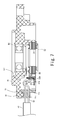
- FIG. 7 is a cross sectional view of the resolver 20 and the bracket 15 .
- an extracting portion 19 arranged between an upper end of the housing 11 and a lower end of the bracket 15 preferably includes a sealing portion 19 a preferably made of an elastic material via which the lead wire 51 is guided inward of the motor 10 from the control device (not shown).
- the sealing portion 19 a preferably includes an insertion hole 19 b through which the lead wire 51 is guided, and seals the inner portion of the brushless motor 10 .
- a protrusion portion 151 is arranged at a bottom surface of the bracket 15 so as to secure the sealing portion 19 a to the bracket 15 .
- FIG. 8 is an enlarged view of a portion shown in FIG. 7 .
- FIG. 8 shows the connecting portion between the lead wire connecting portion 33 and the lead wires 51 .
- the lead wire 51 guided to the inner portion of the brushless motor 10 via the insertion hole 19 b is bent in an upward direction close to an upper portion of the connector portion 32 b .
- a portion of the lead wire 51 will be accommodated in a concave portion 152 arranged at the bracket 15 .
- the lead wire 51 is bent in a downward direction close to the upper portion of the connector portion 32 b and guided to a guiding groove 321 arranged at a radial end portion of the connector portion 32 b.
- the radial end portion of the connector portion 32 b preferably includes a plurality (for example, 6 in the present preferred embodiment) of guiding grooves 321 corresponding to a position of each terminal member.
- the guiding groove 321 in which the lead wire 51 is forced into is a groove extending in a substantially parallel direction with the axial direction of the resolver stator 22 . By virtue of such configuration, the lead wire 51 is latched by the guiding groove 321 .
- the guiding groove 321 preferably has a substantially rectangle shape having round corners. Also, a width of the grove becomes narrower toward an opening portion 321 a which is arranged at the radial end portion of the connector portion 32 b . That is, the connector portion 32 b includes at a portion thereof near the opening portion 321 a a protrusion portion 322 which protrudes toward the opening portion 321 a .
- a width L of the opening portion 321 a is substantially equal to or smaller than a diameter of the lead wire 51 . According to FIG. 9 , the width L is slightly smaller than the diameter of the lead wire 51 .
- the lead wire 51 extends in a downward direction after the lead wire 51 is guided to the guiding groove 321 from the upper portion of the connector portion 32 b . That is, the lead wire 51 will be connected to the lead wire connecting portion 33 via the guiding groove 321 .
- the lead wire connecting portion 33 preferably includes at an end portion thereof a terminal hole 33 a . The lead wire 51 will be soldered, or the like, to the lead wire connecting portion 33 via the terminal hole 33 a.
- the terminal member preferably includes the wire connecting portion 34 to which the wire 38 is connected.
- the control device (not shown) and the coil 39 are connected electrically.
- the connector portion 32 b preferably includes the guiding groove 321 which extends in the axial direction and guides the lead wire 51 .
- the width L of the opening portion 321 a is equal to or smaller than the diameter of the lead wire 51 , and therefore, the lead wire 51 is forced into and retained by the guiding groove 321 .
- the lead wire 51 is connected to the lead wire connecting portion 33 arranged at the bottom end portion of the guiding groove 321 .
- the resolver 20 according to the present preferred embodiment of the present invention and the brushless motor 10 having such resolver are suitable for use in a hydraulically operated and/or electrically operated power steering apparatus used in an automobile or the like.
Applications Claiming Priority (2)
| Application Number | Priority Date | Filing Date | Title |
|---|---|---|---|
| JP2006259887A JP5103845B2 (ja) | 2006-09-26 | 2006-09-26 | レゾルバおよびモータ |
| JP2006-259887 | 2006-09-26 |
Publications (2)
| Publication Number | Publication Date |
|---|---|
| US20080073987A1 US20080073987A1 (en) | 2008-03-27 |
| US7714470B2 true US7714470B2 (en) | 2010-05-11 |
Family
ID=39224177
Family Applications (2)
| Application Number | Title | Priority Date | Filing Date |
|---|---|---|---|
| US11/859,944 Active 2028-07-17 US7714470B2 (en) | 2006-09-26 | 2007-09-24 | Resolver and brushless motor |
| US11/859,950 Active 2028-07-22 US7705505B2 (en) | 2006-09-26 | 2007-09-24 | Brushless Motor |
Family Applications After (1)
| Application Number | Title | Priority Date | Filing Date |
|---|---|---|---|
| US11/859,950 Active 2028-07-22 US7705505B2 (en) | 2006-09-26 | 2007-09-24 | Brushless Motor |
Country Status (4)
| Country | Link |
|---|---|
| US (2) | US7714470B2 (ja) |
| JP (1) | JP5103845B2 (ja) |
| CN (1) | CN101153793B (ja) |
| DE (1) | DE102007044230B4 (ja) |
Cited By (5)
| Publication number | Priority date | Publication date | Assignee | Title |
|---|---|---|---|---|
| US20090134724A1 (en) * | 2007-11-05 | 2009-05-28 | Honda Motor Co., Ltd. | Brushless motor |
| US9819241B2 (en) | 2010-06-14 | 2017-11-14 | Black & Decker Inc. | Stator assembly for a brushless motor in a power tool |
| US10056806B2 (en) | 2010-06-14 | 2018-08-21 | Black & Decker Inc. | Stator assembly for a brushless motor in a power tool |
| RU2717235C1 (ru) * | 2019-08-23 | 2020-03-19 | Акционерное общество "Всероссийский научно-исследовательский проектно-конструкторский и технологический институт электромашиностроения" (АО "ВНИТИ ЭМ") | Способ крепления гибкого внешнего вывода в соединении с выводом обмотки, намотанной на магнитопровод электрической машины |
| US11811287B2 (en) | 2020-06-05 | 2023-11-07 | Milwaukee Electric Tool Corporation | Brushless motor for a power tool |
Families Citing this family (26)
| Publication number | Priority date | Publication date | Assignee | Title |
|---|---|---|---|---|
| US20100037720A1 (en) * | 2008-08-14 | 2010-02-18 | Rose-Hime Designs, Inc. | Robotic manipulator |
| JP5293256B2 (ja) * | 2009-02-20 | 2013-09-18 | 日本精工株式会社 | 回転電機及びこれを用いた電動パワーステアリング装置 |
| US20120262015A1 (en) * | 2009-10-14 | 2012-10-18 | Daesung Electric Co., Ltd. | Resolver of electric driving motor for vehicle |
| JP5923927B2 (ja) * | 2010-10-22 | 2016-05-25 | 日本精工株式会社 | ハーネス保持構造 |
| JP5703691B2 (ja) * | 2010-10-29 | 2015-04-22 | アイシン精機株式会社 | ハイブリッド車両用駆動装置およびその製造方法 |
| EP2639947B1 (en) * | 2010-11-12 | 2019-12-25 | Mitsubishi Electric Corporation | Motor for electric power steering |
| US9337700B2 (en) * | 2011-03-09 | 2016-05-10 | Hamilton Sundstrand Corporation | Terminal assembly with reduced creepage |
| JP6283161B2 (ja) * | 2012-12-19 | 2018-02-21 | 株式会社マキタ | 操作棹を有する作業機 |
| DE102013020427B4 (de) * | 2013-01-31 | 2018-04-05 | Makita Corporation | Arbeitsmaschine mit Bedienstange |
| US9882444B2 (en) * | 2013-04-19 | 2018-01-30 | Mitsubishi Electric Corporation | Rotating electrical machine having a structure for support of a bus bar and terminal block |
| CN108539894B (zh) * | 2013-09-17 | 2020-06-26 | 松下知识产权经营株式会社 | 无刷直流电动机以及搭载了该无刷直流电动机的鼓风装置 |
| JP5845224B2 (ja) * | 2013-09-26 | 2016-01-20 | ファナック株式会社 | ブラケットを有する固定子、固定子を備えた電動機、および電動機の製造方法 |
| JP6175623B2 (ja) * | 2014-01-15 | 2017-08-09 | 多摩川精機株式会社 | リード線引出し構造及び方法 |
| JP6251875B2 (ja) * | 2014-01-22 | 2017-12-27 | 多摩川精機株式会社 | レゾルバケーブルの固定構造 |
| KR101605630B1 (ko) * | 2014-09-05 | 2016-03-23 | 대성전기공업 주식회사 | 레졸버의 절연커버 및 레졸버의 절연커버의 코일 권선방법 |
| JP6423284B2 (ja) * | 2015-02-26 | 2018-11-14 | トヨタ自動車株式会社 | 回転電機駆動車両 |
| JP6992754B2 (ja) * | 2016-08-05 | 2022-01-13 | 日本電産株式会社 | モータ |
| WO2018037965A1 (ja) * | 2016-08-23 | 2018-03-01 | 株式会社デンソー | 位置検出装置、及び、位置検出装置の製造方法 |
| EP3570414B1 (en) * | 2017-01-11 | 2023-09-06 | LG Innotek Co., Ltd. | Motor |
| US11336153B2 (en) | 2017-02-06 | 2022-05-17 | Lg Innotek Co., Ltd. | Motor |
| FR3064696B1 (fr) * | 2017-03-28 | 2021-02-12 | Valeo Systemes De Controle Moteur | Compresseur de suralimentation electrique pour un vehicule automobile |
| JP2018168833A (ja) * | 2017-03-30 | 2018-11-01 | 株式会社豊田自動織機 | 電動圧縮機 |
| WO2019215816A1 (ja) * | 2018-05-08 | 2019-11-14 | 三菱電機株式会社 | エンコーダおよびサーボモータ |
| JP2020167908A (ja) * | 2019-03-29 | 2020-10-08 | 日本電産株式会社 | モータ |
| US11378013B2 (en) * | 2019-04-08 | 2022-07-05 | Hamilton Sundstrand Corporation | Bracket assembly for supporting terminal leads in auxiliary generator for aircraft |
| CN114629301B (zh) * | 2020-08-31 | 2023-12-01 | 广东美的智能科技有限公司 | 电机及具有其的伺服控制系统 |
Citations (19)
| Publication number | Priority date | Publication date | Assignee | Title |
|---|---|---|---|---|
| US4132460A (en) * | 1977-11-07 | 1979-01-02 | Amp Incorporated | Electrical connections to coil windings |
| US4672348A (en) * | 1985-02-19 | 1987-06-09 | Eaton Corporation | Electrical coil assembly and terminal therefor |
| US5770902A (en) | 1995-11-02 | 1998-06-23 | Globe Motors | Motor termination board |
| US5920135A (en) * | 1997-09-24 | 1999-07-06 | Tamagawa Seiki Kabushiki Kaisha | Terminal pin structure of resolver |
| JP3251560B2 (ja) | 1999-04-13 | 2002-01-28 | 多摩川精機株式会社 | 回転検出器構造 |
| US20030006666A1 (en) * | 2001-07-09 | 2003-01-09 | Tamagawa Seiki Kabushiki Kaisha | Resolver stator |
| DE10130117A1 (de) | 2001-06-22 | 2003-01-30 | Minebea Co Ltd | Gehäusedeckel für einen Elektromotor, insbesondere für einen elektronisch kommutierten Gleichstrommotor |
| US20030230945A1 (en) | 2002-06-13 | 2003-12-18 | Masayuki Okubo | Brushless motor |
| US6707185B2 (en) * | 2002-01-08 | 2004-03-16 | Mitsubishi Denki Kabushiki Kaisha | Electric power steering apparatus |
| US6753629B2 (en) | 2001-02-23 | 2004-06-22 | Mitsubishi Denki Kabushiki Kaisha | Brushless DC motor |
| US6815853B2 (en) * | 2002-11-20 | 2004-11-09 | Minebea Co., Ltd. | Stator structure for a resolver |
| US20040263010A1 (en) * | 2003-06-30 | 2004-12-30 | Katsushi Sato | Motor |
| US20050280320A1 (en) * | 2004-04-14 | 2005-12-22 | Mitsubishi Denki Kabushiki Kaisha | Resolver |
| US7105961B2 (en) * | 2001-10-12 | 2006-09-12 | Minebea Co., Ltd. | Lead terminal structure of resolver |
| US20070205679A1 (en) * | 2004-04-15 | 2007-09-06 | Takahiro Terauchi | Brushless Motor |
| US20070241625A1 (en) | 2004-04-30 | 2007-10-18 | Takahiro Terauchi | Brushless motor |
| US7453175B2 (en) * | 2005-04-11 | 2008-11-18 | Nidec Corporation | Brushless motor |
| US7476996B2 (en) * | 2004-10-07 | 2009-01-13 | Tamagawa Seiki Kabushiki Kaisha | Resolver external conductor fixing structure |
| US7595572B2 (en) * | 2006-06-05 | 2009-09-29 | Nidec Corporation | Motor |
Family Cites Families (8)
| Publication number | Priority date | Publication date | Assignee | Title |
|---|---|---|---|---|
| JPH08149733A (ja) * | 1994-11-17 | 1996-06-07 | Hitachi Ltd | 電動機用固定子鉄心端子接続装置 |
| JPH09298857A (ja) * | 1996-04-26 | 1997-11-18 | Mitsumi Electric Co Ltd | モータの端子装置 |
| JPH10327552A (ja) * | 1997-05-23 | 1998-12-08 | Matsushita Electric Ind Co Ltd | ステッピングモータ |
| JP2004007903A (ja) * | 2002-05-31 | 2004-01-08 | Tamagawa Seiki Co Ltd | 回転検出器用ステータ構造 |
| JPWO2005099068A1 (ja) * | 2004-04-09 | 2008-03-06 | 株式会社ミツバ | ブラシレスモータ |
| JP2006223059A (ja) * | 2005-02-10 | 2006-08-24 | Tamagawa Seiki Co Ltd | レゾルバの端子接続構造 |
| JP4760566B2 (ja) * | 2006-06-21 | 2011-08-31 | 日本電産株式会社 | 巻線取付方法 |
| JP4797917B2 (ja) * | 2006-09-29 | 2011-10-19 | 日本電産株式会社 | レゾルバ、モータおよびパワーステアリング装置 |
-
2006
- 2006-09-26 JP JP2006259887A patent/JP5103845B2/ja not_active Expired - Fee Related
-
2007
- 2007-09-17 DE DE102007044230.2A patent/DE102007044230B4/de not_active Expired - Fee Related
- 2007-09-24 US US11/859,944 patent/US7714470B2/en active Active
- 2007-09-24 US US11/859,950 patent/US7705505B2/en active Active
- 2007-09-26 CN CN2007101619112A patent/CN101153793B/zh active Active
Patent Citations (19)
| Publication number | Priority date | Publication date | Assignee | Title |
|---|---|---|---|---|
| US4132460A (en) * | 1977-11-07 | 1979-01-02 | Amp Incorporated | Electrical connections to coil windings |
| US4672348A (en) * | 1985-02-19 | 1987-06-09 | Eaton Corporation | Electrical coil assembly and terminal therefor |
| US5770902A (en) | 1995-11-02 | 1998-06-23 | Globe Motors | Motor termination board |
| US5920135A (en) * | 1997-09-24 | 1999-07-06 | Tamagawa Seiki Kabushiki Kaisha | Terminal pin structure of resolver |
| JP3251560B2 (ja) | 1999-04-13 | 2002-01-28 | 多摩川精機株式会社 | 回転検出器構造 |
| US6753629B2 (en) | 2001-02-23 | 2004-06-22 | Mitsubishi Denki Kabushiki Kaisha | Brushless DC motor |
| DE10130117A1 (de) | 2001-06-22 | 2003-01-30 | Minebea Co Ltd | Gehäusedeckel für einen Elektromotor, insbesondere für einen elektronisch kommutierten Gleichstrommotor |
| US20030006666A1 (en) * | 2001-07-09 | 2003-01-09 | Tamagawa Seiki Kabushiki Kaisha | Resolver stator |
| US7105961B2 (en) * | 2001-10-12 | 2006-09-12 | Minebea Co., Ltd. | Lead terminal structure of resolver |
| US6707185B2 (en) * | 2002-01-08 | 2004-03-16 | Mitsubishi Denki Kabushiki Kaisha | Electric power steering apparatus |
| US20030230945A1 (en) | 2002-06-13 | 2003-12-18 | Masayuki Okubo | Brushless motor |
| US6815853B2 (en) * | 2002-11-20 | 2004-11-09 | Minebea Co., Ltd. | Stator structure for a resolver |
| US20040263010A1 (en) * | 2003-06-30 | 2004-12-30 | Katsushi Sato | Motor |
| US20050280320A1 (en) * | 2004-04-14 | 2005-12-22 | Mitsubishi Denki Kabushiki Kaisha | Resolver |
| US20070205679A1 (en) * | 2004-04-15 | 2007-09-06 | Takahiro Terauchi | Brushless Motor |
| US20070241625A1 (en) | 2004-04-30 | 2007-10-18 | Takahiro Terauchi | Brushless motor |
| US7476996B2 (en) * | 2004-10-07 | 2009-01-13 | Tamagawa Seiki Kabushiki Kaisha | Resolver external conductor fixing structure |
| US7453175B2 (en) * | 2005-04-11 | 2008-11-18 | Nidec Corporation | Brushless motor |
| US7595572B2 (en) * | 2006-06-05 | 2009-09-29 | Nidec Corporation | Motor |
Non-Patent Citations (2)
| Title |
|---|
| Kataoka et al.; "Brushless Motor"; U.S. Appl. No. 11/859,950, filed Sep. 24, 2007. |
| Official communication issued in counterpart German Application No. 10 2007 044 230.2, mailed on Dec. 22, 2008. |
Cited By (8)
| Publication number | Priority date | Publication date | Assignee | Title |
|---|---|---|---|---|
| US20090134724A1 (en) * | 2007-11-05 | 2009-05-28 | Honda Motor Co., Ltd. | Brushless motor |
| US7816827B2 (en) * | 2007-11-05 | 2010-10-19 | Honda Motor Co., Ltd. | Brushless motor |
| US9819241B2 (en) | 2010-06-14 | 2017-11-14 | Black & Decker Inc. | Stator assembly for a brushless motor in a power tool |
| US10056806B2 (en) | 2010-06-14 | 2018-08-21 | Black & Decker Inc. | Stator assembly for a brushless motor in a power tool |
| US10523080B2 (en) | 2010-06-14 | 2019-12-31 | Black & Decker Inc. | Stator assembly for a brushless motor in a power tool |
| US11128194B2 (en) | 2010-06-14 | 2021-09-21 | Black & Decker Inc. | Stator assembly for a brushless motor in a power tool |
| RU2717235C1 (ru) * | 2019-08-23 | 2020-03-19 | Акционерное общество "Всероссийский научно-исследовательский проектно-конструкторский и технологический институт электромашиностроения" (АО "ВНИТИ ЭМ") | Способ крепления гибкого внешнего вывода в соединении с выводом обмотки, намотанной на магнитопровод электрической машины |
| US11811287B2 (en) | 2020-06-05 | 2023-11-07 | Milwaukee Electric Tool Corporation | Brushless motor for a power tool |
Also Published As
| Publication number | Publication date |
|---|---|
| DE102007044230A9 (de) | 2009-06-10 |
| CN101153793B (zh) | 2011-01-26 |
| CN101153793A (zh) | 2008-04-02 |
| US20080073987A1 (en) | 2008-03-27 |
| JP5103845B2 (ja) | 2012-12-19 |
| US20080073988A1 (en) | 2008-03-27 |
| JP2008086056A (ja) | 2008-04-10 |
| DE102007044230A1 (de) | 2008-06-19 |
| US7705505B2 (en) | 2010-04-27 |
| DE102007044230B4 (de) | 2018-02-15 |
Similar Documents
| Publication | Publication Date | Title |
|---|---|---|
| US7714470B2 (en) | Resolver and brushless motor | |
| US7508102B2 (en) | Brushless motor having a circuit board having a central hole and escape holes | |
| JP3816353B2 (ja) | 電動パワーステアリング装置用モータ | |
| JP4774888B2 (ja) | モータ | |
| CN108155762B (zh) | 分解器及电机 | |
| EP2290788A1 (en) | Motor | |
| JP2009118610A (ja) | ブラシレスモータ | |
| JP2008187787A (ja) | レゾルバおよびモータ | |
| EP1583202B1 (en) | Stepping motor with dual-layer bobbin cover | |
| KR20080078950A (ko) | 모터 | |
| CN105359383A (zh) | 旋转电机的磁铁飞散防止以及保持构造 | |
| KR100883597B1 (ko) | 모터 | |
| JP4847727B2 (ja) | 回転電機 | |
| JP2012177587A (ja) | レゾルバ、及びこれを備えたレゾルバ付き軸受 | |
| CN108702054B (zh) | 轴向间隙型旋转电机 | |
| KR20170045663A (ko) | 버스바 및 이를 포함하는 모터 | |
| CN107925299B (zh) | 定子、马达、盘驱动装置以及定子的制造方法 | |
| KR100883595B1 (ko) | 모터 | |
| KR100883596B1 (ko) | 모터 | |
| JP4186728B2 (ja) | ステッピングモータ | |
| KR100883598B1 (ko) | 모터 | |
| CN112910147A (zh) | 定子、马达及定子的制造方法 | |
| CN217883061U (zh) | 马达和电气设备 | |
| US20230101842A1 (en) | Motor | |
| US11715991B2 (en) | Brushless motor |
Legal Events
| Date | Code | Title | Description |
|---|---|---|---|
| AS | Assignment |
Owner name: NIDEC CORPORATION, JAPAN Free format text: ASSIGNMENT OF ASSIGNORS INTEREST;ASSIGNORS:KATAOKA, NAKABA;NAKANISHI, KEITA;YAMASHITA, YOSHIAKI;REEL/FRAME:019867/0475 Effective date: 20070913 Owner name: NIDEC CORPORATION,JAPAN Free format text: ASSIGNMENT OF ASSIGNORS INTEREST;ASSIGNORS:KATAOKA, NAKABA;NAKANISHI, KEITA;YAMASHITA, YOSHIAKI;REEL/FRAME:019867/0475 Effective date: 20070913 |
|
| FEPP | Fee payment procedure |
Free format text: PAYOR NUMBER ASSIGNED (ORIGINAL EVENT CODE: ASPN); ENTITY STATUS OF PATENT OWNER: LARGE ENTITY |
|
| STCF | Information on status: patent grant |
Free format text: PATENTED CASE |
|
| FPAY | Fee payment |
Year of fee payment: 4 |
|
| MAFP | Maintenance fee payment |
Free format text: PAYMENT OF MAINTENANCE FEE, 8TH YEAR, LARGE ENTITY (ORIGINAL EVENT CODE: M1552) Year of fee payment: 8 |
|
| MAFP | Maintenance fee payment |
Free format text: PAYMENT OF MAINTENANCE FEE, 12TH YEAR, LARGE ENTITY (ORIGINAL EVENT CODE: M1553); ENTITY STATUS OF PATENT OWNER: LARGE ENTITY Year of fee payment: 12 |