US7448429B2 - Method for squeezing foundry sand, a match plate, and an upper and a lower flask - Google Patents
Method for squeezing foundry sand, a match plate, and an upper and a lower flask Download PDFInfo
- Publication number
- US7448429B2 US7448429B2 US11/587,633 US58763306A US7448429B2 US 7448429 B2 US7448429 B2 US 7448429B2 US 58763306 A US58763306 A US 58763306A US 7448429 B2 US7448429 B2 US 7448429B2
- Authority
- US
- United States
- Prior art keywords
- plate
- squeeze
- foundry sand
- flask
- match plate
- Prior art date
- Legal status (The legal status is an assumption and is not a legal conclusion. Google has not performed a legal analysis and makes no representation as to the accuracy of the status listed.)
- Active, expires
Links
Images


Classifications
-
- B—PERFORMING OPERATIONS; TRANSPORTING
- B22—CASTING; POWDER METALLURGY
- B22C—FOUNDRY MOULDING
- B22C15/00—Moulding machines characterised by the compacting mechanism; Accessories therefor
- B22C15/02—Compacting by pressing devices only
-
- B—PERFORMING OPERATIONS; TRANSPORTING
- B22—CASTING; POWDER METALLURGY
- B22D—CASTING OF METALS; CASTING OF OTHER SUBSTANCES BY THE SAME PROCESSES OR DEVICES
- B22D18/00—Pressure casting; Vacuum casting
- B22D18/02—Pressure casting making use of mechanical pressure devices, e.g. cast-forging
-
- B—PERFORMING OPERATIONS; TRANSPORTING
- B22—CASTING; POWDER METALLURGY
- B22C—FOUNDRY MOULDING
- B22C19/00—Components or accessories for moulding machines
- B22C19/02—Mould tables
-
- B—PERFORMING OPERATIONS; TRANSPORTING
- B22—CASTING; POWDER METALLURGY
- B22C—FOUNDRY MOULDING
- B22C21/00—Flasks; Accessories therefor
Definitions
- This invention relates to a method for squeezing sand and producing a match plate. Particularly, it relates to a method for squeezing the foundry sand filled in an upper and a lower molding space defined by a match plate, an upper and a lower flask, and an upper and a lower squeeze plate. Further, it relates to the match plate and the upper and the lower flask.
- the inventors of this invention have developed the following apparatus for molding a mold:
- the apparatus is comprised of an upper and a lower molding space, an aeration mechanism to discharge foundry sand into the molding spaces, and a squeezing mechanism to squeeze the foundry sand,
- the upper and the lower molding space are defined by an upper and a lower flask each having intakes disposed at their side walls for foundry sand, a match plate disposed between the upper and the lower flask, and the squeezing mechanism having squeeze plates, which can be inserted in openings of the upper and the lower flask having no match plate.
- the squeezing mechanism squeezes the foundry sand in the upper and the lower molding space by causing the upper and the lower squeeze plates to further approach each other.
- Patent document 1 Japanese Patent Laid-open Publication No. H 0 6-277800
- Patent document 2 Japanese Patent Laid-open Publication No. S59-024552
- the problem to be solved by the present invention is that the hardness and strength near the inner surface that corresponds to the match plate, of an upper and a lower mold that are made by using the conventional apparatus that can perform the following process, are not high enough:
- the process is comprised of:
- this is a method for squeezing foundry sand filled in an upper and a lower molding space defined by a match plate, an upper and a lower flask, and an upper and a lower squeeze plate, comprising:
- a first squeezing step to squeeze the foundry sand in the upper and the lower molding space by causing the upper and the lower squeeze plate to further approach each other
- a second squeezing step to squeeze the foundry sand in the upper and the lower molding space by causing the pattern portions of the match plate to move to each of the upper and the lower squeeze plate.
- a method for squeezing foundry sand comprising:
- the match plate being comprised of:
- a first squeezing step to squeeze the foundry sand in the upper and lower molding space by causing the upper and the lower squeeze plate to further approach each other
- a second squeezing step to squeeze the foundry sand in the upper and the lower molding space by causing the pattern and/or the plate of the pattern portions of the match plate to move to each of the upper and the lower squeeze plate.
- this invention is composed of the following:
- the process is further comprised of a step to squeeze the foundry sand of the upper and the lower molding space by causing the upper and the lower squeeze plate to further approach each other, and a step to squeeze the foundry sand of the upper and the lower molding space by causing the pattern portions of the match plate to move to each of the upper and the lower squeeze plate.
- FIG. 1 shows a diagram to explain the processes of the preferred embodiments of this invention.
- FIG. 2 shows an elevational view of a major portion of an apparatus for molding an upper and a lower mold having no flask which is used in this invention.
- FIG. 3 shows an enlarged view of a part “A” of FIG. 2 .
- FIG. 4( a ) shows a plain view indicating an embodiment of an arrangement of compression coil springs 10 , 10 .
- FIG. 4( b ) shows a plain view indicating another embodiment of an arrangement of the compression coil springs 10 , 10 .
- FIG. 4( c ) shows a plain view indicating another embodiment of an arrangement of the compression coil springs 10 , 10 .
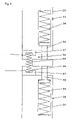
- FIG. 5( a ) shows a cross section of an elevational view indicating a state before squeezing foundry sand in an embodiment of this invention.
- FIG. 5( b ) shows a cross section of an elevational view indicating a state while squeezing foundry sand in an embodiment of this invention.
- FIG. 6 shows an enlarged view of a part “B” of FIG. 5( a ).
- FIG. 7( a ) shows a plain view indicating an embodiment of an arrangement of compression coil springs 23 , 23 .
- FIG. 7( b ) shows a plain view indicating another embodiment of an arrangement of the compression coil springs 23 , 23 .
- FIG. 7( c ) shows a plain view indicating another embodiment of an arrangement of the compression coil springs 23 , 23 .
- FIG. 8( a ) shows a cross section of an elevational view indicating a state before squeezing foundry sand in an embodiment of this invention.
- FIG. 8( b ) shows a cross section of an elevational view indicating a state while squeezing foundry sand in an embodiment of this invention.
- FIG. 9 shows an enlarged view of a part “C” of FIG. 8( a ).
- FIG. 10 shows a plain view indicating an embodiment of an arrangement of pins 33 , 33 and the compression coil springs 23 , 23 .
- FIG. 11 shows a cross section of an elevational view of another embodiment of this invention.
- the present invention which uses an apparatus for molding an upper and a lower mold having no flask, is now explained in detail based on FIG. 2 .
- the apparatus is comprised of:
- the apparatus for molding molds which uses the match plate can be used regardless of whether the molds have a flask.
- this invention can be applied to an apparatus for molding molds having not only one set of flasks, but also two sets of flasks.
- the squeeze means of this invention is comprised of actuators and squeeze plates or squeeze feet.
- the squeeze means can individually squeeze the foundry sand.
- the actuators that are driven by hydraulic pressure, air pressure, and electric motors can be used as the actuators. It is preferable to use the actuators driven by the hydraulic pressure from the aspect of the magnitude of the output of the power. It is further preferable to use the actuators driven by the electric motors since they need no piping system for the hydraulic pressure.
- green sand as foundry sand, which green sand uses bentonite as a binder.
- An expanding and contracting means 8 is disposed at the peripheral border of the pattern portion of the body 3 a of the match plate as shown in FIGS. 2-4 , wherein the expanding and contracting means 8 can be expanded and contracted by being pressed with end surfaces of an upper and a lower flask 1 , 2 , which surfaces oppose the match plate 3 . As shown in FIG.
- the expanding and contracting means 8 is comprised of a plurality of compression coil-springs 10 , 10 disposed in a plurality of through-holes 9 , 9 formed at the body 3 a of the match plate, and support members 11 , 11 having a frame-like structure to hold the plurality of the compression coil-springs 10 , 10 by compressing them at both sides of the coil-springs 10 , 10 , wherein the support members 11 , 11 are mounted on the body 3 a of the match plate.
- the total force of the coil-springs should be more than the force that can support the weight of the upper and the lower flask 1 , 2 .
- the foundry sand is filled in the upper and the lower molding space defined by a match plate 3 , an upper and a lower flask 1 , 2 , and an upper and a lower squeeze plate 4 , 5 as shown in FIG. 1( a ). Then, the foundry sand in the upper and the lower molding space is squeezed by causing the upper and the lower squeeze plate 4 , 5 to further approach each other as shown in FIG.
- the compression coil-springs 10 , 10 of the expanding and contracting means 8 of the match plate 3 are compressed by pressing the lower flask 2 toward the match plate 3 by causing the cylinders 14 , 14 to expand.
- each of the pattern portions of the match plate 3 moves relatively toward the upper and the lower squeeze plate 4 , 5 . Consequently, the foundry sand in the upper and the lower molding space is further squeezed.
- the upper and the lower lifting and lowering frame 12 , 13 are fixed by tie-rods (not shown).
- the expanding and contracting means 20 is disposed at the peripheral border of the pattern portion of the match plate 21 as shown in FIGS. 5-7 , wherein the expanding and contracting means 20 can be expanded and contracted by being pressed with the end surfaces of an upper and a lower flask 1 , 2 , which surfaces oppose the match plate 21 .
- the expanding and contracting means 20 is comprised of a plurality of compression coil-springs 23 , 23 disposed in a plurality of through-holes 22 , 22 formed at the match plate 21 , and support members 24 , 24 having a frame-like structure and a U-like configuration at its cross section to.
- FIG. 7 it is possible to dispose a plurality of the compression coil-springs 23 , 23 of the expanding and contracting means 20 with the following arrangements: arranging them at the entire circumference of the peripheral border of the pattern portion at even intervals as shown in FIG. 7( a ), arranging them at two longitudinal sides of the peripheral border of the pattern portion at even intervals as shown in FIG. 7( b ) and arranging them at two lateral sides of the peripheral border of the pattern portion at even intervals as shown in FIG. 7( c ).
- the total force of the coil-springs should be more than the force that can support the weight of the upper and the lower flask 1 , 2 .
- the foundry sand is filled in the upper and the lower molding space defined by a match plate 21 , an upper and a lower flask 1 , 2 , and an upper and a lower squeeze plate 4 , 5 as shown in FIG. 5( a ). Then, the foundry sand in the upper and the lower molding space is squeezed by causing the upper and the lower squeeze plate 4 , 5 to further approach each other as shown in FIG. 5( b ). Next, the compression coil-springs 23 , 23 of the expanding and contracting means 20 of the match plate 21 are compressed by pressing the lower flask 2 toward the match plate 21 until the ends of the support members 24 , 24 contact both end surfaces of the match plate 21 . When the compression coil-springs 23 , 23 are compressed, each of the pattern portions of the match plate 21 moves relatively toward the upper and the lower squeeze plate 4 , 5 . Consequently, the foundry sand in the upper and the lower molding space is further squeezed.
- the first expanding and contracting means 32 is disposed at the end surfaces of the upper and the lower flask 30 , 31 , which surfaces oppose the match plate 21 , as shown in FIGS. 8-10 , wherein the first expanding and contracting means 32 can be expanded and contracted by being pressed with the end surfaces of an upper and a lower flask 30 , 31 , which surfaces oppose the match plate 21 . As shown in FIG. 8-10 ,
- the first expanding and contracting means 32 is comprised of pins 33 , 33 that are slidably disposed in the upper and the lower flask 30 , 31 and protrude from the flasks, and a plurality of compression coil-springs 34 , 34 to apply the force so that the pins 33 , 33 are expanded.
- the end surfaces of the pins 33 , 33 extend toward and contact the end surfaces of the match plate 21 .
- the pins 33 , 33 disposed at the first expanding and contracting means 32 contact the four corners of the match plate 21 as shown in FIG. 10 .
- the second expanding and contracting means 35 is disposed at the peripheral border of the pattern portion of the match plate 21 as shown in FIGS. 8-10 .
- the second expanding and contracting means 35 can be expanded and contracted by being pressed with end surfaces of an upper and a lower flask 30 , 31 , which surfaces oppose the match plate 21 . As shown in FIG.
- the second expanding and contracting means 35 is comprised of a plurality of compression coil-springs 36 , 36 disposed in a plurality of through-holes 22 , 22 formed at the match plate 21 , and support members 37 , 37 having a frame-like structure and a U-like configuration at its cross section to hold the plurality of the compression coil-springs 23 , 23 by compressing them with both sides of the coil-springs 23 , 23 .
- the plurality of the compression coil-springs disposed at the second expanding and contracting means 35 are located at the four corners of the support members 37 , 37 as shown in FIG. 10 .
- the foundry sand is filled in the upper and the lower molding space defined by a match plate 21 , an upper and a lower flask 30 , 31 , and an upper and a lower squeeze plate 4 , 5 as shown in FIG. 8( a ). Then, the foundry sand in the upper and the lower molding space is squeezed by causing the upper and the lower squeeze plate 4 , 5 to further approach each other as shown in FIG. 8( b ). Next, the compression coil-springs 36 , 36 of the second expanding and contracting means 35 are compressed by pressing the lower flask 31 toward the match plate 21 until the ends of the support members 37 , 37 contact both end surfaces of the match plate 21 .
- the pins 33 , 33 of the first expanding and contracting means 32 are pushed into the upper and the lower flask 30 , 31 . Consequently, the compression coil-springs 34 , 34 are compressed.
- Each of the pattern portions of the match plate 21 move relatively toward the upper and the lower squeeze plate 4 , 5 by the reaction force of the compression coil-springs 34 , 34 and 36 , 36 . Consequently, the foundry sand in the upper and the lower molding space is further squeezed.
- the compression coil-springs of the first expanding and contracting means 32 are disposed in the upper and the lower flask 30 , 31 , and since the length of the coil-springs can be longer than that of the coil-springs of the second expanding and contracting means 35 , it is possible to increase the force of the coil-springs. Thus, it is possible to reduce the number of the coil-springs that are needed to produce the force to support the weight of the upper and the lower flask.
- the foundry sand in the upper and the lower molding space is squeezed by the relative movement between the upper and the lower flask and the pattern portion of the match plate.
- the method for squeezing the foundry sand is not restricted to these embodiments. It is also possible to squeeze the foundry sand in the upper and the lower molding space by individually moving the pattern portions 41 , 41 of the match plate 40 by any of the actuators 42 , 42 as shown in FIG. 11 .
- the methods use compression coil-springs as the expanding and contracting means.
- the expanding and contracting means is not restricted to the compression coil-springs. It is also possible to use hydraulic cylinders or gas springs as the expanding and contracting means.
- This invention can be widely applied to a molding machine having a match plate, such as a molding machine producing a mold having a flask or having no flask. Further, while the foundry sand is filled or squeezed, it is possible to freely determine the position of the upper and the lower flask.
- the upper and the lower flask can be arranged horizontally or vertically. Further, it is possible to cause the relative position of the upper and the lower flask at the time when the foundry sand is filled to differ from that when it is squeezed.
Landscapes
- Engineering & Computer Science (AREA)
- Mechanical Engineering (AREA)
- Casting Devices For Molds (AREA)
- Processing Of Solid Wastes (AREA)
- Molds, Cores, And Manufacturing Methods Thereof (AREA)
- Mold Materials And Core Materials (AREA)
Applications Claiming Priority (3)
| Application Number | Priority Date | Filing Date | Title |
|---|---|---|---|
| JP2004133547 | 2004-04-28 | ||
| JP2005119147 | 2005-04-18 | ||
| PCT/JP2005/007969 WO2005105339A1 (ja) | 2004-04-28 | 2005-04-27 | 鋳物砂のスクイズ方法、マッチプレート及び上・下鋳枠 |
Publications (2)
| Publication Number | Publication Date |
|---|---|
| US20070227684A1 US20070227684A1 (en) | 2007-10-04 |
| US7448429B2 true US7448429B2 (en) | 2008-11-11 |
Family
ID=35241486
Family Applications (1)
| Application Number | Title | Priority Date | Filing Date |
|---|---|---|---|
| US11/587,633 Active 2025-06-30 US7448429B2 (en) | 2004-04-28 | 2005-04-27 | Method for squeezing foundry sand, a match plate, and an upper and a lower flask |
Country Status (12)
| Country | Link |
|---|---|
| US (1) | US7448429B2 (de) |
| EP (1) | EP1741504B1 (de) |
| JP (1) | JP4301292B2 (de) |
| KR (1) | KR100863104B1 (de) |
| CN (1) | CN1968770B (de) |
| AT (1) | ATE450330T1 (de) |
| BR (1) | BRPI0510454B1 (de) |
| DE (1) | DE602005018034D1 (de) |
| DK (1) | DK1741504T3 (de) |
| EA (1) | EA008631B1 (de) |
| MX (1) | MXPA06012488A (de) |
| WO (1) | WO2005105339A1 (de) |
Families Citing this family (4)
| Publication number | Priority date | Publication date | Assignee | Title |
|---|---|---|---|---|
| JP5076670B2 (ja) * | 2006-08-04 | 2012-11-21 | 新東工業株式会社 | 無枠鋳型造型機 |
| ATE469712T1 (de) * | 2006-12-18 | 2010-06-15 | Sintokogio Ltd | Formmaschine |
| KR101352226B1 (ko) | 2008-08-07 | 2014-01-15 | 로라멘디, 에스.쿱. | 수직 몰드 캐스팅 장치 내에서 밀폐 플레이트를 이동시키기 위한 이동 장치 및 이동 장치를 포함하는 장치 |
| CN107685138B (zh) * | 2017-09-21 | 2024-01-30 | 江苏康柏斯机械科技有限公司 | 一种铸造砂箱 |
Citations (14)
| Publication number | Priority date | Publication date | Assignee | Title |
|---|---|---|---|---|
| US365711A (en) * | 1887-06-28 | Haeeis taboe | ||
| US485764A (en) * | 1892-11-08 | Mulder s flask | ||
| US3406738A (en) * | 1967-04-06 | 1968-10-22 | Heatherwill Co | Automatic matchplate moulding machine |
| US4030535A (en) * | 1974-04-19 | 1977-06-21 | Hitachi Metals, Ltd. | Molding system |
| JPS57142745A (en) * | 1981-02-26 | 1982-09-03 | Ikeda Seisakusho:Kk | Sand blowing device in automatic molding machine |
| JPS5924552A (ja) | 1982-07-30 | 1984-02-08 | Sintokogio Ltd | 無枠式上・下鋳型同時造型機 |
| JPS60158949A (ja) * | 1984-01-30 | 1985-08-20 | Mitsubishi Heavy Ind Ltd | 鋳型造型方法ならびに鋳型造型装置 |
| EP0468355A2 (de) * | 1990-07-27 | 1992-01-29 | Sintokogio Ltd. | Kastenlose Formmaschine |
| EP0493977A2 (de) | 1991-01-02 | 1992-07-08 | Taiyo Chuki Co., Ltd. | Vorrichtung zum Giessen |
| DE4340401A1 (de) | 1992-11-27 | 1994-06-01 | Sintokogio Ltd | Vorrichtung zum gleichzeitigen Herstellen von oberen und unteren Formhälften |
| JPH06277800A (ja) | 1993-03-26 | 1994-10-04 | Sintokogio Ltd | 吹込み式鋳型造型方法およびその装置 |
| JPH08187544A (ja) | 1994-12-28 | 1996-07-23 | Kooyoo:Kk | 砂型脱型用離型剤の噴射装置 |
| JP2000317579A (ja) | 1999-04-30 | 2000-11-21 | Metal Eng Kk | 鋳型造型装置及び造型方法 |
| JP2002361368A (ja) | 2001-06-12 | 2002-12-17 | Metal Eng Kk | 無枠式造型装置の鋳物砂充填方法及び装置 |
Family Cites Families (1)
| Publication number | Priority date | Publication date | Assignee | Title |
|---|---|---|---|---|
| JP2000167647A (ja) * | 1998-12-04 | 2000-06-20 | Taiyo Machinery Co Ltd | 生型用自動振動造型機 |
-
2005
- 2005-04-27 DK DK05736656.9T patent/DK1741504T3/da active
- 2005-04-27 US US11/587,633 patent/US7448429B2/en active Active
- 2005-04-27 CN CN2005800197150A patent/CN1968770B/zh active Active
- 2005-04-27 JP JP2006512797A patent/JP4301292B2/ja active Active
- 2005-04-27 EP EP05736656A patent/EP1741504B1/de active Active
- 2005-04-27 AT AT05736656T patent/ATE450330T1/de not_active IP Right Cessation
- 2005-04-27 BR BRPI0510454-8A patent/BRPI0510454B1/pt not_active IP Right Cessation
- 2005-04-27 KR KR1020067024634A patent/KR100863104B1/ko active IP Right Grant
- 2005-04-27 WO PCT/JP2005/007969 patent/WO2005105339A1/ja active Application Filing
- 2005-04-27 DE DE602005018034T patent/DE602005018034D1/de active Active
- 2005-04-27 MX MXPA06012488A patent/MXPA06012488A/es active IP Right Grant
- 2005-04-27 EA EA200601996A patent/EA008631B1/ru not_active IP Right Cessation
Patent Citations (15)
| Publication number | Priority date | Publication date | Assignee | Title |
|---|---|---|---|---|
| US365711A (en) * | 1887-06-28 | Haeeis taboe | ||
| US485764A (en) * | 1892-11-08 | Mulder s flask | ||
| US3406738A (en) * | 1967-04-06 | 1968-10-22 | Heatherwill Co | Automatic matchplate moulding machine |
| US4030535A (en) * | 1974-04-19 | 1977-06-21 | Hitachi Metals, Ltd. | Molding system |
| JPS57142745A (en) * | 1981-02-26 | 1982-09-03 | Ikeda Seisakusho:Kk | Sand blowing device in automatic molding machine |
| JPS5924552A (ja) | 1982-07-30 | 1984-02-08 | Sintokogio Ltd | 無枠式上・下鋳型同時造型機 |
| JPS60158949A (ja) * | 1984-01-30 | 1985-08-20 | Mitsubishi Heavy Ind Ltd | 鋳型造型方法ならびに鋳型造型装置 |
| EP0468355A2 (de) * | 1990-07-27 | 1992-01-29 | Sintokogio Ltd. | Kastenlose Formmaschine |
| EP0493977A2 (de) | 1991-01-02 | 1992-07-08 | Taiyo Chuki Co., Ltd. | Vorrichtung zum Giessen |
| DE4340401A1 (de) | 1992-11-27 | 1994-06-01 | Sintokogio Ltd | Vorrichtung zum gleichzeitigen Herstellen von oberen und unteren Formhälften |
| US5409052A (en) | 1992-11-27 | 1995-04-25 | Sintokogio, Ltd. | Device for simultaneously forming cope and drag molds |
| JPH06277800A (ja) | 1993-03-26 | 1994-10-04 | Sintokogio Ltd | 吹込み式鋳型造型方法およびその装置 |
| JPH08187544A (ja) | 1994-12-28 | 1996-07-23 | Kooyoo:Kk | 砂型脱型用離型剤の噴射装置 |
| JP2000317579A (ja) | 1999-04-30 | 2000-11-21 | Metal Eng Kk | 鋳型造型装置及び造型方法 |
| JP2002361368A (ja) | 2001-06-12 | 2002-12-17 | Metal Eng Kk | 無枠式造型装置の鋳物砂充填方法及び装置 |
Also Published As
| Publication number | Publication date |
|---|---|
| EP1741504A1 (de) | 2007-01-10 |
| DE602005018034D1 (de) | 2010-01-14 |
| EA200601996A1 (ru) | 2007-02-27 |
| KR20070012511A (ko) | 2007-01-25 |
| DK1741504T3 (da) | 2010-04-06 |
| JP4301292B2 (ja) | 2009-07-22 |
| JPWO2005105339A1 (ja) | 2008-03-13 |
| CN1968770A (zh) | 2007-05-23 |
| US20070227684A1 (en) | 2007-10-04 |
| MXPA06012488A (es) | 2007-01-31 |
| WO2005105339A1 (ja) | 2005-11-10 |
| EA008631B1 (ru) | 2007-06-29 |
| BRPI0510454A (pt) | 2007-10-30 |
| CN1968770B (zh) | 2010-12-22 |
| EP1741504A4 (de) | 2007-09-12 |
| BRPI0510454B1 (pt) | 2013-04-09 |
| ATE450330T1 (de) | 2009-12-15 |
| KR100863104B1 (ko) | 2008-10-13 |
| EP1741504B1 (de) | 2009-12-02 |
Similar Documents
| Publication | Publication Date | Title |
|---|---|---|
| EP2514540B1 (de) | Formungsverfahren zum simultanen herstellen von oberer und unterer form und kastenlose formmaschine | |
| CN1214880C (zh) | 铸型造型方法及装置 | |
| JP5126695B2 (ja) | 抜枠鋳型造型装置 | |
| US7448429B2 (en) | Method for squeezing foundry sand, a match plate, and an upper and a lower flask | |
| JP2011098364A (ja) | 同時鋳型造型方法及び抜枠鋳型造型装置 | |
| US3284858A (en) | Molding machine and head with pressure compensating provision | |
| CN207563738U (zh) | 一种新型磁性材料模具 | |
| JP2001300692A (ja) | 鋳物砂の圧縮方法およびその装置 | |
| CN210450968U (zh) | 粉末冶金成形装置用取料机械手 | |
| CN110534332B (zh) | 烧结磁体制备方法及其压力成型设备 | |
| JP2000135599A (ja) | 熱プレス装置 | |
| KR100297192B1 (ko) | 가동 프레임식 프레스 | |
| CN213793823U (zh) | 一种多功能环保设备的模具 | |
| JP3057259U (ja) | 柔軟性ダイス | |
| CN216659017U (zh) | 一种功率电感的成型模具 | |
| CN215241555U (zh) | 一种自动塑形的冷等静压成型模具 | |
| CN211941344U (zh) | 耐火砖用压砖机 | |
| JP4352395B2 (ja) | 鋳物砂の圧縮方法およびその装置 | |
| JPS638728Y2 (de) | ||
| JP3453408B2 (ja) | クランプ手段付きのプレス装置 | |
| CN114474831A (zh) | 一种功率电感的成型模具及其成型方法 | |
| JPH01119604A (ja) | 粉末成形法 | |
| JPS6135301Y2 (de) | ||
| CN106476129A (zh) | 一种可实现双向压制的布料车装置 | |
| JPH09157702A (ja) | 圧粉成形装置 |
Legal Events
| Date | Code | Title | Description |
|---|---|---|---|
| AS | Assignment |
Owner name: SINTOKOGIO, LTD., JAPAN Free format text: ASSIGNMENT OF ASSIGNORS INTEREST;ASSIGNORS:HIRATA, MINORU;TERABE, TOKIYA;SAKAGUCHI, KOICHI;REEL/FRAME:018485/0153 Effective date: 20061012 |
|
| STCF | Information on status: patent grant |
Free format text: PATENTED CASE |
|
| FPAY | Fee payment |
Year of fee payment: 4 |
|
| FPAY | Fee payment |
Year of fee payment: 8 |
|
| FEPP | Fee payment procedure |
Free format text: PAYOR NUMBER ASSIGNED (ORIGINAL EVENT CODE: ASPN); ENTITY STATUS OF PATENT OWNER: LARGE ENTITY Free format text: PAYER NUMBER DE-ASSIGNED (ORIGINAL EVENT CODE: RMPN); ENTITY STATUS OF PATENT OWNER: LARGE ENTITY |
|
| MAFP | Maintenance fee payment |
Free format text: PAYMENT OF MAINTENANCE FEE, 12TH YEAR, LARGE ENTITY (ORIGINAL EVENT CODE: M1553); ENTITY STATUS OF PATENT OWNER: LARGE ENTITY Year of fee payment: 12 |