US7245104B2 - Position-sensorless motor control device - Google Patents
Position-sensorless motor control device Download PDFInfo
- Publication number
- US7245104B2 US7245104B2 US11/503,247 US50324706A US7245104B2 US 7245104 B2 US7245104 B2 US 7245104B2 US 50324706 A US50324706 A US 50324706A US 7245104 B2 US7245104 B2 US 7245104B2
- Authority
- US
- United States
- Prior art keywords
- axis
- current
- motor
- superposed
- voltage
- Prior art date
- Legal status (The legal status is an assumption and is not a legal conclusion. Google has not performed a legal analysis and makes no representation as to the accuracy of the status listed.)
- Active
Links
Images


Classifications
-
- H—ELECTRICITY
- H02—GENERATION; CONVERSION OR DISTRIBUTION OF ELECTRIC POWER
- H02P—CONTROL OR REGULATION OF ELECTRIC MOTORS, ELECTRIC GENERATORS OR DYNAMO-ELECTRIC CONVERTERS; CONTROLLING TRANSFORMERS, REACTORS OR CHOKE COILS
- H02P21/00—Arrangements or methods for the control of electric machines by vector control, e.g. by control of field orientation
- H02P21/22—Current control, e.g. using a current control loop
Definitions
- the present invention relates to a position-sensorless motor control device that drives and controls a motor without the use of a rotor position sensor.
- the present invention also relates to a motor drive system incorporating such a position-sensorless motor control device.
- JP-A-2003-219682 discloses a technique according to which a high-frequency rotation voltage is applied to a motor, and the rotor position thereof is estimated based on the major-axis direction of the ellipse described by the current vector locus.
- JP-A-2004-80986 discloses a technique according to which a high-frequency rotation voltage is applied to a motor, and the current that flows therethrough is converted into a current on the ⁇ - ⁇ axes; then the peak values and the phases of the ⁇ -axis and ⁇ -axis components of this current are detected to find the angle of the ellipse major axis (d axis) from the ⁇ axis.
- JP-A-2002-51597 discloses a technique according to which the cosine and the sine of the mid-angle between the in-phase magnetic flux vector and the mirror-phase magnetic flux vector of a high-frequency wave are estimated, and these estimated values are used as rotation signals for a vector rotator.
- JP-A-2003-153582 discloses a technique according to which a mapping between the positive-phase axis and the negative-phase axis is exploited to estimate the rotor position.
- a position-sensorless motor control device that controls the motor such that the axis error between the d- and ⁇ -axes is reduced is provided with: a superposer that superposes, on the drive current with which the motor is driven, a superposed current having a different frequency than the drive current; a superposed component extractor that extracts, from the motor current fed to the motor, the ⁇ -axis and ⁇ -axis components of the superposed current; and a controller that reduces the axis error by controlling the motor based on the arithmetic product of the motor
- the superposer may superpose the superposed current on the drive current by superposing a superposed voltage commensurate with the superposed current on the drive voltage that is applied to the motor to pass the drive current therethrough.
- the controller may reduce the axis error by controlling the motor based on the direct-current component of the arithmetic product.
- the controller may reduce the axis error by controlling the motor such that the direct-current component converges to zero.
- the voltage vector locus of the superposed voltage on the ⁇ - ⁇ axes may describe a figure symmetric about the ⁇ or ⁇ axis.
- the voltage vector locus of the superposed voltage on the ⁇ - ⁇ axes may describe a perfect circle, or an ellipse having the minor or major axis thereof on the ⁇ axis, or a line segment on the ⁇ or ⁇ axis.
- the motor may be a non-salient-pole motor
- the superposed voltage that the superposer superposes on the drive voltage may be a voltage that causes the d-axis component of the inductance of the motor to vary by magnetic saturation attributable to the ⁇ -axis component of the superposed current.
- the position-sensorless motor control device having the first configuration described above can be used even with a non-salient-pole motor.
- a position-sensorless motor control device that controls the motor such that the axis error between the d- and ⁇ -axes is reduced is provided with: a superposer that superposes, on the drive current with which the motor is driven, a superposed current having a different frequency than the drive current; a superposed component extractor that extracts the ⁇ -axis and ⁇ -axis components of the superposed voltage that is applied to the motor to superpose the superposed current on the drive current; and a controller that reduces the axis error by controlling the motor based on the
- the controller may reduce the axis error by controlling the motor based on the direct-current component of the arithmetic product.
- the controller may reduce the axis error by controlling the motor such that the direct-current component converges to zero.
- the current vector locus of the superposed current on the ⁇ - ⁇ axes may describe a figure symmetric about the ⁇ or ⁇ axis.
- the current vector locus of the superposed current on the ⁇ - ⁇ axes describes a perfect circle, or an ellipse having the minor or major axis thereof on the ⁇ axis, or a line segment on the ⁇ or ⁇ axis.
- the motor may be a non-salient-pole motor
- the superposed current that the superposer superposes on the drive current may be a current that causes the d-axis component of the inductance of the motor to vary by magnetic saturation attributable to the ⁇ -axis component of the superposed current.
- the position-sensorless motor control device having the second configuration described above can be used even with a non-salient-pole motor.
- a motor drive system is provided with: a motor; an inverter for driving the motor; and the position-sensorless motor control device having the first or second configuration described above, which controls the motor by controlling the inverter.
- FIG. 1 is a block diagram showing the overall configuration of a motor drive system according to the present invention
- FIG. 2 is an analysis model diagram of the motor shown in FIG. 1 ;
- FIG. 3 is a configuration block diagram of the motor drive system of a first embodiment of the present invention.
- FIG. 4 is a diagram showing an example of the voltage vector locus (here, a perfect-circle voltage vector locus) of the superposed voltage outputted from the superposed voltage generator shown in FIG. 3 ;
- FIG. 5 is a diagram showing the current vector locus of the superposed current that flows according to the superposed voltage shown in FIG. 4 ;
- FIG. 6 is a waveform diagram showing the arithmetic product of the ⁇ -axis and ⁇ -axis components of the superposed current and the direct-current component of the arithmetic product (in a case where the axis error is zero);
- FIG. 7 is a waveform diagram showing the arithmetic product of the ⁇ -axis and ⁇ -axis components of the superposed current and the direct-current component of the arithmetic product (in a case where the axis error is non-zero);
- FIG. 8 is a block diagram showing an example of the internal configuration of the position/speed estimator shown in FIG. 3 ;
- FIG. 9 is a block diagram showing another example of the internal configuration of the position/speed estimator shown in FIG. 3 ;
- FIG. 10 is a block diagram showing another example of the internal configuration of the position/speed estimator shown in FIG. 3 ;
- FIG. 11 is a diagram showing another example of the voltage vector locus (here, a elliptic voltage vector locus) of the superposed voltage outputted from the superposed voltage generator shown in FIG. 3 ;
- FIG. 12 is a diagram showing the current vector locus of the superposed current that flows according to the superposed voltage shown in FIG. 11 ;
- FIG. 13 is a diagram showing the current vector locus of the superposed current in a case where the superposed voltage outputted from the superposed voltage generator shown in FIG. 3 is a single-phase alternating voltage;
- FIG. 14 is a diagram showing an example of the waveform (here, a rectangular wave) of the superposed voltage outputted from the superposed voltage generator shown in FIG. 3 ;
- FIG. 15 is a diagram showing the voltage vector locus corresponding to the waveform shown in FIG. 14 ;
- FIG. 16 is a diagram showing the current vector locus of the superposed current that flows according to the superposed voltage shown in FIG. 15 ;
- FIG. 17 is a diagram showing the current vector locus of the superposed current in a case where the motor shown in FIG. 3 is a non-salient-pole motor;
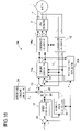
- FIG. 18 is a configuration block diagram of the motor drive system of a second embodiment of the present invention.
- FIG. 19 is a diagram showing an example of the current vector locus (here, a perfect-circle current vector locus) of the superposed current outputted from the superposed current generator shown in FIG. 18 ;
- FIG. 20 is a diagram showing the voltage vector locus of the superposed voltage that is applied according to the superposed current shown in FIG. 19 ;
- FIG. 21 is a block diagram showing an example of the internal configuration of the position/speed estimator shown in FIG. 18 .
- FIG. 1 is a block configuration diagram of a motor drive system to which the present invention is applied.
- Reference numeral 1 represents a three-phase, permanent-magnet, synchronous motor 1 (hereinafter also referred to simply as “motor 1 ”) that has a permanent magnet on the rotor (unillustrated) thereof and that has an armature winding on the stator (unillustrated) thereof.
- the motor 1 may be a salient-pole motor (a motor having a salient pole) or a non-salient-pole motor (a motor having no salient pole). The operation with a non-salient-pole motor will be discussed later and until then the following description mainly deals with a case where the motor 1 is a salient-pole motor (for example, an interior-permanent-magnet synchronous motor).
- Reference numeral 2 represents a PWM (pulse-width modulation) inverter, which feeds the motor 1 with a three-phase alternating-current voltage, in U, V, and W phases, according to the rotor position of the motor 1 .
- This voltage fed to the motor 1 is called the motor voltage V a
- the current fed from the inverter 2 to the motor 1 is called the motor current (armature current) I a .
- Reference numeral 3 represents a position-sensorless control device, which estimates, based on the motor current I a , the rotor position or the like of the motor 1 , and feeds the inverter 2 with a signal for rotating the motor 1 at a desired rotation speed.
- the desired rotation speed here is fed, in the form of a specified motor speed value ⁇ * from an unillustrated CPU (central processing unit) or the like to the position-sensorless control device 3 .
- FIG. 2 is an analysis model diagram of the motor 1 .
- armature winding always refers to that provided in the motor 1 .
- FIG. 2 shows, as fixed axes, the U-phase, V-phase, and W-phase armature winding fixed axes.
- Reference numeral 1 a represents the permanent magnet that forms the rotor of the motor 1 .
- the direction of the magnetic flux produced by the permanent magnet 1 a is called the d axis
- the axis estimated, for the purpose of control, to correspond to the d axis is called the ⁇ axis.
- the axis that leads the d axis by an electrical angle of 90 degrees in phase is called the q axis
- the axis estimated to lead the ⁇ axis by an electrical angle of 90 degrees in phase is called the ⁇ axis.
- the rotating coordinate system has, as its coordinate axes, the d and q axes, which are collectively called the d-q axes.
- the rotating coordinate system estimated for the purpose of control (estimated rotating coordinate system) has, as its coordinate axes, the ⁇ and ⁇ axis, which are collectively called the ⁇ - ⁇ axes.
- the d-q axes rotates, and their rotation speed is called the real motor speed ⁇ .
- the ⁇ - ⁇ axes also rotates, and their rotation speed is called the estimated motor speed ⁇ e .
- the phase of the d axis at a given moment is represented by ⁇ (the real rotor position ⁇ ) relative to the U-phase armature winding fixed axis.
- the phase of the ⁇ axis at a given moment is represented by ⁇ e (the estimated rotor position ⁇ e ) relative to the U-phase armature winding fixed axis.
- the ⁇ -axis component, the ⁇ -axis component, the d-axis component, and the q-axis component of the motor voltage V a are called the ⁇ -axis voltage v ⁇ , the ⁇ -axis voltage v ⁇ , the d-axis voltage V d , and the q-axis voltage V q , respectively; and the ⁇ -axis component, the ⁇ -axis component, the d-axis component, and the q-axis component of the motor current I a are called the ⁇ -axis current i ⁇ , the ⁇ -axis current i ⁇ , the d-axis current i d , and the q-axis current i q , respectively.
- R a represents the motor resistance (the resistance of the armature winding of the motor 1 );
- L d and L q represents the d-axis inductance and the q-axis inductance (the d-axis component and the q-axis component of the inductance of the armature winding of the motor 1 ), respectively;
- ⁇ a represents the armature flux linkage attributable to the permanent magnet 1 a .
- FIG. 3 is a configuration block diagram of the motor drive system, showing in detail the internal configuration of the position-sensorless control device 3 shown in FIG. 1 .
- the position-sensorless control device 3 is composed of a current detector 11 , a coordinate converter 12 , a subtracter 13 , a subtracter 14 , a current controller 15 , a magnetic flux controller 16 , a speed controller 17 , a coordinate converter 18 , a subtracter 19 , a position/speed estimator (hereinafter also referred to simply as “estimator”) 20 , a superposed voltage generator 21 , and adders 22 and 23 .
- the individual functional blocks of the position-sensorless control device 3 can freely use, whenever necessary, all the values generated within the position-sensorless control device 3 .
- the current detector 11 is implemented with, for example, a Hall device, and detects the U-phase current i u and the V-phase current i v of the motor current I a fed from the PWM inverter 2 to the motor 1 .
- the detection results from the current detector 11 namely the U-phase current i u and the V-phase current i v , are fed to the coordinate converter 12 , which then converts them, by using the estimated rotor position ⁇ e fed from the estimator 20 , into a ⁇ -axis current i ⁇ and a ⁇ -axis current i ⁇ .
- the conversion here is performed according to formula (1) below.
- the estimator 20 estimates and outputs the estimated rotor position ⁇ e and the estimated motor speed ⁇ e . How the estimated rotor position ⁇ e and the estimated motor speed ⁇ e are estimated here will be described later.
- the subtracter 19 subtracts the estimated motor speed ⁇ e fed from the estimator 20 from the specified motor speed value ⁇ *, and outputs the subtraction result (speed error). Based on this subtraction result ( ⁇ * ⁇ e ) from the subtracter 19 , the speed controller 17 produces a specified ⁇ -axis current value i ⁇ *.
- This specified ⁇ -axis current value i ⁇ * represents the value to be kept up with by the ⁇ -axis current i ⁇ , i.e. the ⁇ -axis component of the motor current I a .
- the magnetic flux controller 16 produces a specified ⁇ -axis current value i ⁇ *.
- This specified ⁇ -axis current value i ⁇ * represents the value to be kept up with by the ⁇ -axis current i y , i.e. the ⁇ -axis component of the motor current I a .
- the subtracter 13 subtracts the ⁇ -axis current i ⁇ outputted from the coordinate converter 12 from the specified ⁇ -axis current value i ⁇ * outputted from the magnetic flux controller 16 to calculate the current error (i ⁇ * ⁇ i ⁇ ).
- the subtracter 14 subtracts the ⁇ -axis current i ⁇ outputted from the coordinate converter 12 from the specified ⁇ -axis current value i ⁇ * outputted from the speed controller 17 to calculate the current error (i ⁇ * ⁇ i ⁇ ).
- the current errors calculated by the subtracters 13 and 14 , the ⁇ -axis current i ⁇ and the ⁇ -axis current i ⁇ from the coordinate converter 12 , and the estimated motor speed ⁇ e from the estimator 20 are fed to the current controller 15 , which then outputs a specified ⁇ -axis voltage value v ⁇ * and a specified ⁇ -axis voltage value v ⁇ * such that the ⁇ -axis current i ⁇ keeps up with the specified ⁇ -axis current value i ⁇ * and that the ⁇ -axis current i ⁇ keeps up with the specified ⁇ -axis current value i ⁇ *.
- the superposed voltage generator 21 outputs a superposed voltage to be superposed on the specified ⁇ -axis voltage value v ⁇ * and the specified ⁇ -axis voltage value v ⁇ *.
- the superposed voltage consists of, as a ⁇ -axis component and a ⁇ -axis component thereof, a ⁇ -axis superposed voltage vh ⁇ and a ⁇ -axis superposed voltage vh ⁇ .
- the superposed voltage will be described in detail later.
- the adder 22 calculates the sum (v ⁇ *+vh ⁇ ) of the specified ⁇ -axis voltage value v ⁇ * from the current controller 15 and the ⁇ -axis superposed voltage vh ⁇ from the superposed voltage generator 21 .
- the adder 23 calculates the sum (v ⁇ *+vh ⁇ ) of the specified ⁇ -axis voltage value v ⁇ * from the current controller 15 and the ⁇ -axis superposed voltage vh ⁇ from the superposed voltage generator 21 .
- the coordinate converter 18 Based on the estimated rotor position ⁇ e fed from the estimator 20 , the coordinate converter 18 converts backward the specified ⁇ -axis voltage value v ⁇ having the ⁇ -axis superposed voltage vh ⁇ superposed thereon and the specified ⁇ -axis voltage value v ⁇ * having the ⁇ -axis superposed voltage vh ⁇ superposed thereon; thereby the coordinate converter 18 produces specified three-phase voltage values consisting of a specified U-phase voltage value v u *, a specified V-phase voltage value v v *, and a specified W-phase voltage value v w *, which represent the U-phase component, the V-phase component, and the W-phase component of the motor voltage V a , and then outputs them to the inverter 2 .
- the backward conversion here is performed according to formula (2), consisting of two equations, below.
- the inverter 2 Based on the specified three-phase voltage values (v u *, v v *, and v w *), which represent the voltage to be applied to the motor 1 , the inverter 2 produces pulse-width-modulated signals, and feeds the motor 1 with a motor current I a commensurate with those specified three-phase voltage values to drive the motor 1 .
- the specified ⁇ -axis voltage value v ⁇ * and the specified ⁇ -axis voltage value v ⁇ * represent the voltage values to be kept up with by the ⁇ -axis voltage v ⁇ and the ⁇ -axis voltage v ⁇ , which are the ⁇ -axis component and the ⁇ -axis component of the motor voltage V a , respectively; as a result of the above-described superposition of the superposed voltage, now the ⁇ -axis voltage v ⁇ and the ⁇ -axis voltage v ⁇ keep up with (v ⁇ *+vh ⁇ ) and (v ⁇ *+vh ⁇ ), respectively.
- the motor current I a is commensurate only with the specified ⁇ -axis current value i ⁇ * and the specified ⁇ -axis current value i ⁇ *.
- the current represented by the specified ⁇ -axis current value i ⁇ * and the specified ⁇ -axis current value i ⁇ * is the drive current with which the motor 1 is driven.
- the specified ⁇ -axis voltage value v ⁇ * and the specified ⁇ -axis voltage value v ⁇ * are produced based on the specified ⁇ -axis current value i ⁇ * and the specified ⁇ -axis current value i ⁇ * so that the motor 1 is driven at the desired rotation speed ( ⁇ *).
- the voltage represented by the specified ⁇ -axis voltage, value v ⁇ * and the specified ⁇ -axis voltage value v ⁇ * is the drive voltage that is applied to the motor 1 to pass the drive current therethrough.
- Superposing a non-zero superposed voltage (the ⁇ -axis superposed voltage vh ⁇ and the ⁇ -axis superposed voltage v ⁇ ) on the specified ⁇ -axis voltage value v ⁇ * and the specified ⁇ -axis voltage value v ⁇ * is equivalent to superposing the superposed voltage on the drive voltage.
- the drive current has superposed thereon a superposed current commensurate with the superposed voltage.
- the superposed voltage generated by the superposed voltage generator 21 is a high-frequency rotation voltage.
- “high frequency” denotes that the frequency of the superposed voltage is sufficiently higher than that of the drive voltage. Accordingly, the frequency of the superposed current superposed commensurate with the superposed voltage is sufficiently higher than that of the drive current.
- “rotation voltage” denotes a voltage of which the voltage vector locus describes a circle on the ⁇ - ⁇ axes (in the ⁇ - ⁇ coordinate system) as shown in FIGS. 4 and 11 .
- a rotation voltage is a three-phase balanced voltage, and with such a three-phase balanced voltage, its voltage vector locus describes a perfect circle having its center at the origin of the ⁇ - ⁇ axes, like the voltage vector locus shown in FIG. 4 . Since this rotation voltage is a high-frequency voltage that is not synchronous with the motor 1 , applying the rotation voltage to the motor 1 does not cause it to rotate.
- the current vector locus of the superposed current that is made to flow through the motor 1 by the superposed voltage exhibiting the voltage vector locus 70 describes, as indicated by a current vector locus 71 in FIG. 5 , an ellipse that has its center at the origin on the ⁇ - ⁇ axes (in the ⁇ - ⁇ coordinate system) and that has its major-axis direction running on the ⁇ -axis direction and its minor-axis direction running on the ⁇ -axis direction. It should be noted that the current vector locus 71 is one observed when the axis error ⁇ is zero.
- the current vector locus of the superposed current describes an ellipse as indicated by a current vector locus 72 , and its major-axis direction (or minor-axis direction) does not coincide with the ⁇ -axis (or ⁇ -axis) direction. That is, when the axis error ⁇ is non-zero, on the ⁇ - ⁇ axes (in the ⁇ - ⁇ coordinate system), the current vector locus 71 is inclined about the origin so as to describe the current vector locus 72 instead.
- the ⁇ -axis component and the ⁇ -axis component of the superposed current be called the ⁇ -axis superposed current ih ⁇ and the ⁇ -axis superposed current ih ⁇ , respectively.
- their arithmetic product (ih ⁇ ⁇ ih ⁇ ) contains a direct-current component that depends on the inclination of the ellipse described by the current vector locus 72 .
- the arithmetic product (ih ⁇ ⁇ ih ⁇ ) is positive in the first and third quadrants of the current vector locus and negative in the second and fourth quadrants thereof.
- the arithmetic product when the ellipse is not inclined (when the current vector locus 71 is observed), the arithmetic product contains no direct-current component; when the ellipse is inclined (when the current vector locus 72 is observed), the arithmetic product contains a direct-current component.
- the roman numerals I, II, III, and IV represent the first, second, third, and fourth quadrants on the ⁇ - ⁇ axes (in the ⁇ - ⁇ coordinate system).
- the direct-current component increases as the magnitude of the axis error ⁇ increases (is largely proportional to the axis error ⁇ ).
- the direct-current component is so controlled as to converge to zero, the axis error ⁇ converges to zero.
- FIG. 8 is a block diagram showing an example of the internal configuration of the estimator 20 .
- the estimator 20 shown in FIG. 8 is composed of band-pass filters (hereinafter abbreviated to “BPFs”) 31 and 32 , a multiplier 33 , a low-pass filter (hereinafter abbreviated to “LPF”) 34 , a proportional-plus-integral calculator 35 , and an integrator 36 .
- BPFs band-pass filters
- LPF low-pass filter
- the BPF 31 extracts, from the value of the ⁇ -axis current i ⁇ outputted from the coordinate converter 12 , the ⁇ -axis superposed current ih ⁇ , which is the component superposed thereon.
- the BPF 32 extracts, from the value of the ⁇ -axis current i ⁇ outputted from the coordinate converter 12 , the ⁇ -axis superposed current ih ⁇ , which is the component superposed thereon.
- the multiplier 33 calculates the arithmetic product (ih ⁇ ⁇ ih ⁇ ) of the ⁇ -axis superposed current ih ⁇ and the ⁇ -axis superposed current ih ⁇ extracted by the BPFs 31 and 32 .
- the LPF 34 removes a high-frequency component from the arithmetic product (ih ⁇ ⁇ ih ⁇ ), and thereby extracts the direct-current component ihD of the arithmetic product (ih ⁇ ⁇ ih ⁇ ).
- the proportional-plus-integral calculator 35 while cooperating with the individual functional blocks of the position-sensorless control device 3 , performs proportional-plus-integral control, and thereby calculates the estimated motor speed ⁇ e such that the direct-current component ihD outputted from the LPF 34 converges to zero (i.e. so that the axis error ⁇ converges to zero).
- the integrator 36 integrates the estimated motor speed ⁇ e outputted from the proportional-plus-integral calculator 35 to calculate the estimated rotor position ⁇ e .
- the estimated motor speed ⁇ e outputted from the proportional-plus-integral calculator 35 and the estimated rotor position ⁇ e outputted from the integrator 36 are both, as the output values of the estimator 20 , fed to the relevant functional blocks of the position-sensorless control device 3 that need them.
- the axis error ⁇ can be made to converge to zero.
- the processing required to estimate the rotor position is simpler (the amount of computational operation required to do that is smaller) than is conventionally required, and is easy to realize. This offers high practicality.
- the rotor position can be properly estimated. Needless to say, no position sensor (unillustrated) any longer needs to be provided in the motor drive system. This is expected to lead to reduced cost and other benefits.
- an n-period integrator 37 that integrates the arithmetic product (ih ⁇ ⁇ ih ⁇ ) of n-period worth (where n is an integer equal to or greater than one) of the superposed voltage may be used to extract the direct-current component ihD.
- the n-period integrator 37 may be further replaced with a moving averager (unillustrated) that calculates the direct-current component ihD from the moving averages of the arithmetic product (ih ⁇ ⁇ ih ⁇ ) of n-period worth of the superposed voltage.
- the LPF 34 in FIG. 8 may be replaced with an LPF 38 and a moving averager 39 .
- the LPF 38 is like the LPF 34 .
- the moving averager 39 calculates the moving averages (the moving averages of n-period worth of the superposed voltage) of the arithmetic product (ih ⁇ ⁇ ih ⁇ ) having the high-frequency component removed therefrom by the LPF 38 , and thereby calculates the direct-current component ihD.
- the moving averages the moving averages of n-period worth of the superposed voltage
- the arithmetic product ih ⁇ ⁇ ih ⁇
- the example described above deals with a case where the voltage vector locus of the superposed voltage describes, on the ⁇ - ⁇ axes, a perfect circle having its center at the origin, like the voltage vector locus 70 shown in FIG. 4 .
- the amplitude of the ⁇ -axis superposed voltage vh ⁇ and the amplitude of the ⁇ -axis superposed voltage vh ⁇ may be different.
- the voltage vector locus 73 describes an ellipse that has its center at the origin on the ⁇ - ⁇ axes (in the ⁇ - ⁇ coordinate system) and that has its minor-axis direction running on the ⁇ -axis direction and its major-axis direction running on the ⁇ -axis direction.
- the current vector locus of the superposed current that flows as a result describes an ellipse elongate in the ⁇ -axis direction as shown in FIG. 12 .
- the current vector locus of the superposed current describes, as indicated by a current vector locus 74 , an ellipse (or a perfect circle in some cases) that has its center at the origin on the ⁇ - ⁇ axes (in the ⁇ - ⁇ coordinate system) and that has its major-axis or minor-axis direction running on the ⁇ -axis direction; thus, the arithmetic product (ih ⁇ ⁇ ih ⁇ ) contains no direct-current component.
- the estimator 20 shown in FIG. 8 etc. can estimate the rotor position.
- the superposed voltage is a single-phase high-frequency voltage (a high-frequency alternating voltage in the ⁇ phase) consisting only of a ⁇ -axis voltage component; or only the ⁇ -axis superposed voltage vh ⁇ may be made zero, in which case the superposed voltage is a single-phase high-frequency voltage (a high-frequency alternating voltage in the ⁇ phase) consisting only of a ⁇ -axis voltage component. Since this single-phase alternating voltage also is a high-frequency voltage that is not synchronous with the motor 1 , applying the alternating voltage to the motor 1 does not cause it to rotate.
- the voltage vector locus of the superposed voltage describes a line segment having its mid point at the origin on the ⁇ - ⁇ axes (in the ⁇ - ⁇ coordinate system) and lying on the ⁇ -axis.
- the current vector locus of the superposed current describes a line segment having its mid point at the origin on the ⁇ - ⁇ axes (in the ⁇ - ⁇ coordinate system) as indicated by a current vector locus 77 in FIG.
- the estimator 20 shown in FIG. 8 etc. can estimate the rotor position.
- the ⁇ -axis superposed voltage vh ⁇ and the ⁇ -axis superposed voltage vh ⁇ be sine waves, but it is not always necessary that the ⁇ -axis superposed voltage vh ⁇ and/or the ⁇ -axis superposed voltage vh ⁇ be sine waves.
- the ⁇ -axis superposed voltage vh ⁇ and the ⁇ -axis superposed voltage vh ⁇ may be given any waveforns.
- the voltage vector locus of the superposed voltage on the ⁇ - ⁇ axes (in the ⁇ - ⁇ coordinate system) describes a figure that encloses the origin and that is symmetric about the ⁇ -axis or the ⁇ -axis, just as in a case where a two-phase rotation voltage is adopted as the superposed voltage, when the axis error ⁇ equals 0°, the arithmetic product (ih ⁇ ⁇ ih ⁇ ) contains no direct-current component and, as the magnitude of the axis error ⁇ increases from 0°, the direct-current component of the arithmetic product (ih ⁇ ⁇ ih ⁇ ) increases starting with zero.
- the above-noted expression “enclose the origin” denotes that the origin on the ⁇ - ⁇ axes (in the ⁇ - ⁇ coordinate system) lies inside the above-mentioned “figure that is symmetric”. It should also be understood that the above-noted expression “symmetric about the ⁇ -axis” denotes that, of the voltage vector locus on the ⁇ - ⁇ axes (in the ⁇ - ⁇ coordinate system), the part lying in the first and second quadrants and the part lying in the third and fourth quadrants are symmetric with each other about the ⁇ -axis.
- the ⁇ -axis superposed voltage vh ⁇ (solid line 82 ) and the ⁇ -axis superposed voltage vh ⁇ (broken line 83 ) may be rectangular waves.
- their voltage vector locus describes a rectangular having its center at the origin on the ⁇ - ⁇ axes (in the ⁇ - ⁇ coordinate system) as indicated by a voltage vector locus 84 in FIG. 15
- the current vector locus of the superposed current that flows as a result describes (substantially) a lozenge as shown in FIG. 16 .
- This lozenge described by the current vector locus of the superposed current is, when the axis error ⁇ is zero, as indicated by a current vector locus 85 ; thus, the arithmetic product (ih ⁇ ⁇ ih ⁇ ) contains no direct-current component.
- the current vector locus of the superposed current changes from the current vector locus 85 to a current vector locus 86 ; that is, the lozenge becomes distorted, and the arithmetic product (ih ⁇ ⁇ ih ⁇ ) comes to have a direct-current component.
- the estimator 20 shown in FIG. 8 etc. can estimate the rotor position.
- a surface-permanent-magnet synchronous motor which is a type of non-salient-pole motor, may be adopted. It should be noted, however, that, in a case where a non-salient-pole motor is used as the motor 1 , when the voltage vector locus of the superposed voltage on the ⁇ - ⁇ axes (in the ⁇ - ⁇ coordinate system) describes a perfect circle, like the voltage vector locus 70 shown in FIG. 4 (i.e.
- the current vector locus of the superposed current on the ⁇ - ⁇ axes (in the ⁇ - ⁇ coordinate system) also describes a perfect circle having its center at the origin, as indicated by a current vector locus 80 in FIG. 17 (provided that no magnetic saturation is occurring).
- the current vector locus of the superposed current describes a perfect circle, if the perfect circle becomes inclined as a result of the axis error ⁇ being non-zero, the inclination cannot be grasped.
- a superposed voltage that causes the d-axis inductance L d of the motor 1 , which is here a non-salient-pole motor, to vary by magnetic saturation attributable to the ⁇ -axis superposed current ih ⁇ .
- the superposed voltage and the superposed current both high-frequency, the ⁇ -axis superposed voltage vh ⁇ and the ⁇ -axis superposed current ih ⁇ are substantially proportional to each other, and the ⁇ -axis superposed voltage vh ⁇ and the ⁇ -axis superposed current ih ⁇ are substantially proportional to each other.
- a two-phase rotation voltage in which the amplitude of the ⁇ -axis superposed voltage vh ⁇ and the amplitude of the ⁇ -axis superposed voltage vh ⁇ differ may be adopted as the superposed voltage, or a single-phase alternating voltage may be adopted as the superposed voltage.
- the ⁇ -axis superposed voltage vh ⁇ (the ⁇ -axis superposed current ih ⁇ ) should not be zero.
- the current controller 15 performs necessary computational operation according to two formulae (4a) and (4b) below.
- the magnetic flux controller 16 , the speed controller 17 , and the proportional-plus-integral calculator 35 perform necessary computational operation according to formulae (5), (6), and (7), respectively.
- v ⁇ * ( K cp + K ci s ) ⁇ ( i ⁇ * - i ⁇ ) - ⁇ e ⁇ L q ⁇ i ⁇ ( 4 ⁇ a )
- v ⁇ * ( K cp + K ci s ) ⁇ ( i ⁇ * - i ⁇ ) + ⁇ e ⁇ ( L d ⁇ i ⁇ + ⁇ a ) ( 4 ⁇ b )
- i ⁇ * ⁇ a 2 ⁇ ( L q - L d ) - ⁇ a 2 4 ⁇ ( L q - L d ) 2 + i ⁇ * 2 ( 5 )
- i ⁇ * ( K sp + K si / s ) ⁇ ( ⁇ * - ⁇ e ) ( 6 )
- ⁇ e ( K p + K i / s ) ⁇ ihD ( 7
- K cp , K sp , and K p represent constants of proportionality (proportional gains), and K ci , K si , and K i represent constants of integration (integral gains). These constants are all previously set at the design stage of the motor drive system.
- the superposed voltage is superposed on the input side (namely v ⁇ * and v ⁇ *) of the coordinate converter 18 ; instead, it may be superposed on the output side (namely v U *, v V *, and v W *) of the coordinate converter 18 .
- the values obtained by converting the ⁇ -axis superposed voltage vh ⁇ and the ⁇ -axis superposed voltage vh ⁇ into a three-phase voltage are superposed on the specified three-phase voltage values (v u *, v v *, and v w *).
- FIG. 18 is a detailed configuration block diagram of the motor drive system of the second embodiment.
- the motor drive system of the second embodiment is composed of a motor 1 , an inverter 2 , and a position-sensorless control device 3 a .
- the position-sensorless control device 3 a here differs from the position-sensorless control device 3 shown in FIG.
- the position-sensorless control device 3 a here has basically the same configuration as the position-sensorless control device 3 shown in FIG. 3 .
- the position-sensorless control device 3 a here has basically the same configuration as the position-sensorless control device 3 shown in FIG. 3 .
- FIG. 18 such parts are found also in FIG. 3 are identified by common reference numerals, and in principle no overlapping description will be repeated.
- the motor 1 may be a salient-pole motor (a motor having a salient pole) or a non-salient-pole motor (a motor having no salient pole).
- a salient-pole motor for example, an interior-permanent-magnet synchronous motor.
- the estimator 20 a estimates and outputs the estimated rotor position ⁇ e and the estimated motor speed ⁇ e .
- the individual functional blocks of the position-sensorless control device 3 a perform necessary computational operation by using, whenever necessary, the estimated rotor position ⁇ e and the estimated motor speed ⁇ e estimated by the estimator 20 a .
- the individual functional blocks of the position-sensorless control device 3 a can freely use, whenever necessary, all the values generated within the position-sensorless control device 3 a.
- the subtracter 19 subtracts the estimated motor speed ⁇ e fed from the estimator 20 a from the specified motor speed value ⁇ *, and outputs the subtraction result (speed error). Based on this subtraction result ( ⁇ * ⁇ e ) from the subtracter 19 , the speed controller 17 produces a specified ⁇ -axis current value i ⁇ *. By using the estimated motor speed ⁇ e fed from the estimator 20 a and the specified ⁇ -axis current value i ⁇ * fed from the speed controller 17 , the magnetic flux controller 16 produces a specified ⁇ -axis current value i ⁇ *.
- the superposed current generator 24 outputs the superposed current to be superposed on the specified ⁇ -axis current value i ⁇ * and the specified ⁇ -axis current value i ⁇ *.
- the superposed current consists of, as a ⁇ -axis component and a ⁇ -axis component thereof, a ⁇ -axis superposed current ih ⁇ and a ⁇ -axis superposed current ih ⁇ .
- the superposed current will be described in detail later.
- the adder 25 calculates the sum (i ⁇ *+ih ⁇ ) of the specified ⁇ -axis current value i ⁇ * from the magnetic flux controller 16 and the ⁇ -axis superposed current ih ⁇ from the superposed current generator 24 .
- the adder 26 calculates the sum (i ⁇ *+ih ⁇ ) of the specified ⁇ -axis current value i ⁇ * from the speed controller 17 and the ⁇ -axis superposed current ih ⁇ from the superposed current generator 24 .
- the subtracter 13 subtracts the ⁇ -axis current i ⁇ outputted from the coordinate converter 12 from the sum (i ⁇ *+ih ⁇ ) calculated by the adder 25 to calculate a current error (i ⁇ *+ih ⁇ ⁇ i ⁇ ).
- the subtracter 14 subtracts the ⁇ -axis current i ⁇ outputted from the coordinate converter 12 from the sum (i ⁇ *+ih ⁇ ) calculated by the adder 26 to calculate a current error (i ⁇ *+ih ⁇ ⁇ -i ⁇ .
- the current errors calculated by the subtracters 13 and 14 , the ⁇ -axis current i ⁇ and the ⁇ -axis current i ⁇ from the coordinate converter 12 , and the estimated motor speed ⁇ e from the estimator 20 a are fed to the current controller 15 a , which then outputs a specified ⁇ -axis voltage value v ⁇ * and a specified ⁇ -axis voltage value v ⁇ * such that the ⁇ -axis current i ⁇ keeps up with the specified ⁇ -axis current value (namely (i ⁇ *+ih ⁇ )) having the ⁇ -axis superposed current ih ⁇ superposed thereon, and that the ⁇ -axis current i ⁇ keeps up with the specified ⁇ -axis current value (namely (i ⁇ *+ih ⁇ )) having the ⁇ -axis superposed current ih ⁇ superposed thereon.
- the specified ⁇ -axis voltage value v ⁇ * and the specified ⁇ -axis voltage value v ⁇ * contains a superposed voltage (superposed component) commensurate with the superposed current.
- the ⁇ -axis component and the ⁇ -axis component of this superposed voltage are called the ⁇ -axis superposed voltage vh ⁇ and the ⁇ -axis superposed voltage vh ⁇ , respectively.
- the ⁇ -axis superposed voltage vh ⁇ has a value commensurate with the ⁇ -axis superposed current ih ⁇
- the ⁇ -axis superposed voltage vh ⁇ has a value commensurate with the ⁇ -axis superposed current ih ⁇ .
- the coordinate converter 18 a Based on the estimated rotor position ⁇ e fed from the estimator 20 a , the coordinate converter 18 a converts backward the specified ⁇ -axis voltage value v ⁇ * and the specified ⁇ -axis voltage value v ⁇ *, both containing the superposed voltage; the coordinate converter 18 a thereby produces specified three-phase voltage values consisting of a specified U-phase voltage value v u *, a specified V-phase voltage value v v *, and a specified W-phase voltage value v w *, which represent the U-phase component, the V-phase component, and the W-phase component of the motor voltage V a , and then outputs them to the inverter 2 .
- the inverter 2 Based on the specified three-phase voltage values (v u *, v v *, and v w *), which represent the voltage to be applied to the motor 1 , the inverter 2 produces pulse-width-modulated signals, and feeds the motor 1 with a motor current I a commensurate with those specified three-phase voltage values to drive the motor 1 .
- the current represented by the specified ⁇ -axis current value i ⁇ * and the specified ⁇ -axis current value i ⁇ * is the drive current with which the motor 1 is driven.
- the voltage represented by the specified ⁇ -axis voltage value v ⁇ * and the specified ⁇ -axis voltage value v ⁇ * is the “drive voltage applied to the motor 1 to pass the drive current therethrough” having added thereto the “superposed voltage applied to the motor 1 to pass therethrough the superposed current generated by the superposed current generator 24 ”.
- the superposed current generated by the superposed current generator 24 is a high-frequency rotation current.
- “high frequency” denotes that the frequency of the superposed current is sufficiently higher than that of the drive current.
- “rotation current” denotes a current of which the current vector locus describes a circle on the ⁇ - ⁇ axes (in the ⁇ - ⁇ coordinate system) as shown in FIG. 19 . Since this rotation current is a high-frequency current that is not synchronous with the motor 1 , applying the rotation current to the motor 1 does not cause it to rotate.
- the ⁇ -axis superposed current ih ⁇ and the ⁇ -axis superposed current ih ⁇ generated by the superposed current generator 24 are so set as to be commensurate with (or equal to), respectively, the ⁇ -axis superposed current ih ⁇ and the ⁇ -axis superposed current ih ⁇ that are expected to be superposed in the first embodiment.
- the voltage vector locus of the superposed voltage contained in the specified ⁇ -axis voltage value v ⁇ * and the specified ⁇ -axis voltage value v ⁇ * describes an ellipse having its center at the origin on the ⁇ - ⁇ axes (in the ⁇ - ⁇ coordinate system) and having its minor-axis direction running on the ⁇ -axis direction and its major-axis direction running on the ⁇ -axis direction, as indicated by a voltage vector locus 91 in FIG. 20 . It should be noted that the voltage vector locus 91 is one observed when the axis error ⁇ is zero.
- the voltage vector locus of the superposed voltage describes an ellipse as indicated by a voltage vector locus 92 , and its minor-axis direction (or major-axis direction) does not coincide with the ⁇ -axis (or ⁇ -axis) direction. That is, when the axis error ⁇ is non-zero, on the ⁇ - ⁇ axes (in the ⁇ - ⁇ coordinate system), the voltage vector locus 91 is inclined about the origin so as to describe the voltage vector locus 92 instead.
- the rotor position can be estimated.
- the estimator 20 a can estimate the estimated rotor position ⁇ e and the estimated motor speed ⁇ e with the ⁇ - ⁇ axes so modified that the direct-current component of the arithmetic product (vh ⁇ ⁇ vh ⁇ ) converges to zero.
- FIG. 21 is a block diagram showing an example of the internal configuration of the estimator 20 a .
- BPFs band-pass filters
- multiplier 33 a an LPF (low-pass filter) 34 a
- proportional-plus-integral calculator 35 a a proportional-plus-integral calculator
- the BPF 31 a extracts, from the specified ⁇ -axis voltage value v ⁇ * outputted from the current controller 15 a , the ⁇ -axis superposed voltage vh ⁇ , which is the component superposed thereon.
- the BPF 32 a extracts, from the specified ⁇ -axis voltage value V ⁇ * outputted from the current controller 15 a , the ⁇ -axis superposed voltage vh ⁇ , which is the component superposed thereon.
- the multiplier 33 a calculates the arithmetic product (vh ⁇ ⁇ vh ⁇ ) of the ⁇ -axis superposed voltage vh ⁇ and the ⁇ -axis superposed voltage vh ⁇ extracted by the BPFs 31 a and 32 a .
- the LPF 34 a removes a high-frequency component from this arithmetic product (vh ⁇ ⁇ vh ⁇ ), and thereby extracts the direct-current component vhD of the arithmetic product (vh ⁇ ⁇ vh ⁇ ).
- the proportional-plus-integral calculator 35 a while cooperating with the individual functional blocks of the position-sensorless control device 3 a , performs proportional-plus-integral control, and thereby calculates the estimated motor speed ⁇ e such that the direct-current component vhD outputted from the LPF 34 a converges to zero (i.e. so that the axis error ⁇ converges to zero).
- the integrator 36 a integrates the estimated motor speed ⁇ e outputted from the proportional-plus-integral calculator 35 a to calculate the estimated rotor position ⁇ e .
- the estimated motor speed ⁇ e outputted from the proportional-plus-integral calculator 35 a and the estimated rotor position ⁇ e outputted from the integrator 36 a are both, as the output values of the estimator 20 a , fed to the relevant functional blocks of the position-sensorless control device 3 a that need them.
- the axis error ⁇ can be made to converge to zero.
- the processing required to estimate the rotor position is simpler (the amount of computational operation required to do that is smaller) than is conventionally required, and is easy to realize. This offers high practicality.
- the rotor position can be properly estimated. Needless to say, no position sensor (unillustrated) any longer needs to be provided in the motor drive system. This is expected to lead to reduced cost and other benefits.
- the LPF 34 a may be replaced with an n-period integrator (unillustrated) that integrates the arithmetic product (vh ⁇ ⁇ vh ⁇ ) of n-period worth (where n is an integer equal to or greater than one) of the superposed current and that thereby extracts the direct-current component vhD, or may be replaced with a moving averager (unillustrated) that calculates the direct-current component vhD from the moving averages of the arithmetic product (vh ⁇ ⁇ vh ⁇ ) of n-period worth of the superposed current.
- n-period integrator unillustrated
- a moving averager unillustrated
- the amplitude of the ⁇ -axis superposed current ih ⁇ and the amplitude of the ⁇ -axis superposed current ih ⁇ may be different, so long as the voltage vector locus of the superposed voltage commensurate with the superposed current describes an ellipse having its center at the origin on the ⁇ - ⁇ axes (in the ⁇ - ⁇ coordinate system). This is because, even when those amplitudes are different, the direct-current component of the arithmetic product (vh ⁇ ⁇ vh ⁇ ) varies according to the axis error ⁇ .
- the current vector locus of the superposed current describes an ellipse having its center at the origin on the ⁇ - ⁇ axes (in the ⁇ - ⁇ coordinate system) and having its major-axis direction running on the ⁇ -axis direction and its minor-axis direction running on the ⁇ -axis direction.
- the current vector locus of the superposed current describes an ellipse having its center at the origin on the ⁇ - ⁇ axes (in the ⁇ - ⁇ coordinate system) and having its minor-axis direction running on the ⁇ -axis direction and its major-axis direction running on the ⁇ -axis direction.
- only the ⁇ -axis superposed current ih ⁇ may be made zero, in which case the superposed current is a single-phase high-frequency current (a high-frequency alternating current in the ⁇ phase) consisting only of a ⁇ -axis current component; or only the ⁇ -axis superposed current ih ⁇ may be made zero, in which case the superposed current is a single-phase high-frequency current (a high-frequency alternating current in the ⁇ phase) consisting only of a ⁇ -axis current component.
- this single-phase alternating current also is a high-frequency current that is not synchronous with the motor 1 , applying the alternating current to the motor 1 does not cause it to rotate.
- the current vector locus of the superposed current describes a line segment having its mid point at the origin on the ⁇ - ⁇ axes (in the ⁇ - ⁇ coordinate system) and lying on the ⁇ -axis.
- only the ⁇ -axis superposed current ih ⁇ may be made zero.
- the ⁇ -axis superposed current ih ⁇ and the ⁇ -axis superposed current ih ⁇ be sine waves, but it is not always necessary that the ⁇ -axis superposed current ih ⁇ and/or the ⁇ -axis superposed current ih ⁇ be sine waves.
- the ⁇ -axis superposed current ih ⁇ and the ⁇ -axis superposed current ih ⁇ may be given any waveforms.
- the current vector locus of the superposed current on the ⁇ - ⁇ axes (in the ⁇ - ⁇ coordinate system) describes a figure that encloses the origin and that is symmetric about the ⁇ -axis or the ⁇ -axis, just as in a case where a two-phase rotation current is adopted as the superposed current, when the axis error ⁇ equals 0°, the arithmetic product (vh ⁇ ⁇ vh ⁇ ) contains no direct-current component and, as the magnitude of the axis error ⁇ increases from 0°, the direct-current component of the arithmetic product (vh ⁇ ⁇ vh ⁇ ) increases starting with zero.
- the ⁇ -axis superposed current ih ⁇ and the ⁇ -axis superposed current ⁇ may be rectangular waves.
- the above-noted expression “enclose the origin” denotes that the origin on the ⁇ - ⁇ axes (in the ⁇ - ⁇ coordinate system) lies inside the above-mentioned “figure that is symmetric”. It should also be understood that the above-noted expression “symmetric about the ⁇ -axis” denotes that, of the current vector locus on the ⁇ - ⁇ axes (in the ⁇ - ⁇ coordinate system), the part lying in the first and second quadrants and the part lying in the third and fourth quadrants are symmetric with each other about the ⁇ -axis.
- a surface-permanent-magnet synchronous motor which is a type of non-salient-pole motor, may be adopted. It should be noted, however, that, in a case where a non-salient-pole motor is used as the motor 1 , when the current vector locus of the superposed current on the ⁇ - ⁇ axes (in the ⁇ - ⁇ coordinate system) describes a perfect circle, like the current vector locus 90 shown in FIG. 19 (i.e.
- the voltage vector locus of the superposed voltage on the ⁇ - ⁇ axes (in the ⁇ - ⁇ coordinate system) also describes a perfect circle having its center at the origin (provided that no magnetic saturation is occurring).
- the voltage vector locus of the superposed voltage describes a perfect circle, if the perfect circle becomes inclined as a result of the axis error ⁇ being non-zero, the inclination cannot be grasped.
- the direct-current component of the arithmetic product (vh ⁇ ⁇ vh ⁇ ) has a non-zero value.
- the rotor position can be estimated. Specifically, it is advisable to superpose on the drive current a superposed current that causes the d-axis inductance L d of the motor 1 , which is here a non-salient-pole motor, to vary by magnetic saturation attributable to the ⁇ -axis superposed current ih ⁇ .
- a two-phase rotation current in which the amplitude of the ⁇ -axis superposed current ih ⁇ and the amplitude of the ⁇ -axis superposed current ih ⁇ differ may be adopted as the superposed current, or a single-phase alternating current may be adopted as the superposed current.
- the ⁇ -axis superposed current ih ⁇ should not be zero.
- the current controller 15 a performs necessary computational operation according to the formula obtained by replacing the term (i ⁇ * ⁇ i ⁇ ) in the right side of formula (4a) above with (i ⁇ *+ih ⁇ ⁇ i 65 ) and the formula obtained by replacing the term (i ⁇ * ⁇ i ⁇ ) in the righ formula (4b) above with (i ⁇ *+ih ⁇ ⁇ i ⁇ ).
- the proportional-plus-integral calculator 35 a performs necessary computational operation according to the formula obtained by replacing the term ihD in the right side of formula (7) above with vhD.
- the superposed voltage generator 21 and the adders 22 and 23 together form a superposer (voltage superposer).
- the BPFs 31 and 32 and the multiplier 33 together form a superposed component extractor.
- This superposed component extractor may be regarded as including a functional block that outputs the direct-current component ihD.
- the superposed component extractor may be regarded as including the LPF 34 , the n-period integrator 37 , or a moving averager (unillustrated), or as including the LPF 38 and the moving averager 39 .
- the functional blocks of the position-sensorless control device 3 other than those mentioned above as forming the superposer and the superposed component extractor together form a controller.
- the superposed current generator 24 and the adders 25 and 26 together form a superposer.
- the BPFs 31 a and 32 a and the multiplier 33 a together form a superposed component extractor.
- This superposed component extractor may be regarded as including a functional block that outputs the direct-current component vhD.
- the superposed component extractor may be regarded as including the LPF 34 a , an n-period integrator (unillustrated), or a moving averager (unillustrated).
- the functional blocks of the position-sensorless control device 3 a other than those mentioned above as forming the superposer and the superposed component extractor together form a controller.
- the current detector 11 may be so configured as to directly detect the motor current as shown in FIG. 3 etc; instead, it may be so configured as to detect the motor current by reproducing it from the instantaneous current of the power-source-side DC current.
- the present invention is suitable for all kinds of electric appliances that employ motors.
- the present invention is suitable, in particular, in electric cars that are driven by the rotation of motors and in compressors and the like that are used in air conditioners and the like.
Landscapes
- Engineering & Computer Science (AREA)
- Power Engineering (AREA)
- Control Of Ac Motors In General (AREA)
- Control Of Motors That Do Not Use Commutators (AREA)
Applications Claiming Priority (2)
| Application Number | Priority Date | Filing Date | Title |
|---|---|---|---|
| JP2005235720A JP4425193B2 (ja) | 2005-08-16 | 2005-08-16 | モータの位置センサレス制御装置 |
| JPJP2005-235720 | 2005-08-16 |
Publications (2)
| Publication Number | Publication Date |
|---|---|
| US20070040528A1 US20070040528A1 (en) | 2007-02-22 |
| US7245104B2 true US7245104B2 (en) | 2007-07-17 |
Family
ID=37738269
Family Applications (1)
| Application Number | Title | Priority Date | Filing Date |
|---|---|---|---|
| US11/503,247 Active US7245104B2 (en) | 2005-08-16 | 2006-08-14 | Position-sensorless motor control device |
Country Status (3)
| Country | Link |
|---|---|
| US (1) | US7245104B2 (enExample) |
| JP (1) | JP4425193B2 (enExample) |
| CN (2) | CN100499351C (enExample) |
Cited By (22)
| Publication number | Priority date | Publication date | Assignee | Title |
|---|---|---|---|---|
| US20080315816A1 (en) * | 2007-06-22 | 2008-12-25 | Sanyo Electric Co., Ltd. | Motor Control Device And Compressor |
| US20090128069A1 (en) * | 2007-11-16 | 2009-05-21 | Hitachi, Ltd. | Motor Control Apparatus and Control Apparatus for hybrid Electric Vehicles |
| US20090218974A1 (en) * | 2005-09-02 | 2009-09-03 | Christian Paintz | Driving brushless dc (bldc) motors |
| US20090273308A1 (en) * | 2008-04-30 | 2009-11-05 | Rockwell Automation Technologies, Inc. | Position sensorless control of permanent magnet motor |
| US20100097017A1 (en) * | 2008-10-17 | 2010-04-22 | Oteman David G | System and method for controlling power balance in an electrical/mechanical system |
| US20100141192A1 (en) * | 2008-12-10 | 2010-06-10 | Melexis Tessenderlo Nv | Operation of bldc motors |
| US20100156334A1 (en) * | 2008-12-24 | 2010-06-24 | Aisin Aw Co., Ltd. | Sensorless motor control device |
| US20100188033A1 (en) * | 2008-09-23 | 2010-07-29 | Aerovironment, Inc. | Sensorless optimum torque control for high efficiency ironless permanent magnet machine |
| US20110074327A1 (en) * | 2009-09-21 | 2011-03-31 | Melexis Tessenderlo Nv | Control of sinusoidally driven brushless dc (bldc) motors |
| US20110148336A1 (en) * | 2009-12-22 | 2011-06-23 | Denso Corporation | Motor control device and method for controlling brushless motor |
| US20110221371A1 (en) * | 2008-08-28 | 2011-09-15 | Melexis Nv, Microelectronic Integrated Systems | Accuracy of rotor position detection relating to the control of brushless dc motors |
| WO2012033688A2 (en) | 2010-09-10 | 2012-03-15 | Wisconsin Alumni Research Foundation | Permanent magnet motor with stator-based saliency for position sensorless drive |
| US8796978B2 (en) | 2008-09-23 | 2014-08-05 | Aerovironment, Inc. | Predictive pulse width modulation for an open delta H-bridge driven high efficiency ironless permanent magnet machine |
| US20140346984A1 (en) * | 2012-02-22 | 2014-11-27 | Kabushiki Kaisha Yaskawa Denki | Magnetic pole position estimating apparatus for electric motor, controlling apparatus for electric motor, and magnetic pole position estimating method for electric motor |
| US20150091483A1 (en) * | 2012-02-28 | 2015-04-02 | Calsonic Kansei Corporation | Electric Motor Control Device |
| US20150115862A1 (en) * | 2012-07-09 | 2015-04-30 | Kabushiki Kaisha Yaskawa Denki | Motor control apparatus and motor system |
| US20150214865A1 (en) * | 2014-01-26 | 2015-07-30 | Zhongshan Broad-Ocean Motor Co., Ltd. | Dc permanent magnet synchronous motor |
| US9300234B2 (en) * | 2014-01-17 | 2016-03-29 | Kabushiki Kaisha Yaskawa Denki | Rotary electric machine controller, rotary electric machine control method, and method of creating control map |
| US20180052009A1 (en) * | 2016-08-17 | 2018-02-22 | Hyundai Mobis Co., Ltd. | Device and method of estimating rotor angle in motor |
| US10830610B2 (en) | 2016-09-26 | 2020-11-10 | Analog Devices, Inc. | Method and apparatus for motor rotor position determination |
| US11196371B2 (en) | 2020-01-10 | 2021-12-07 | DRiV Automotive Inc. | Sensorless position detection for electric motor |
| US11226037B2 (en) * | 2016-09-09 | 2022-01-18 | Denso Corporation | Shift range control device |
Families Citing this family (39)
| Publication number | Priority date | Publication date | Assignee | Title |
|---|---|---|---|---|
| JP4716118B2 (ja) * | 2006-03-29 | 2011-07-06 | 株式会社ジェイテクト | モータ制御装置 |
| JP5109416B2 (ja) * | 2007-03-06 | 2012-12-26 | 株式会社デンソー | 回転機の制御装置 |
| JP2008220096A (ja) * | 2007-03-06 | 2008-09-18 | Toshiba Corp | 同期電動機のセンサレス制御装置 |
| JP5176406B2 (ja) * | 2007-05-24 | 2013-04-03 | 日本電産株式会社 | 交流電動機の回転子位相速度推定装置 |
| JP5176420B2 (ja) | 2007-08-02 | 2013-04-03 | 株式会社ジェイテクト | ブラシレスモータのセンサレス制御装置 |
| JP2009055748A (ja) | 2007-08-29 | 2009-03-12 | Sanyo Electric Co Ltd | 電流検出ユニット及びモータ制御装置 |
| JP5534292B2 (ja) * | 2008-06-30 | 2014-06-25 | 株式会社ジェイテクト | 車両用操舵装置 |
| DE502008002884D1 (de) * | 2008-07-07 | 2011-04-28 | Baumueller Nuernberg Gmbh | Verfahren und Anordnung zur Beobachtung der Antriebsgeschwindigkeit eines Permanentmagnet-Läufers in einem Antriebsregelkreis |
| JP5376856B2 (ja) * | 2008-08-01 | 2013-12-25 | キヤノン株式会社 | 通信システム及び受信装置、並びにそれらの制御方法 |
| JP5324159B2 (ja) | 2008-08-20 | 2013-10-23 | 三洋電機株式会社 | モータ制御装置 |
| JP5281339B2 (ja) * | 2008-09-01 | 2013-09-04 | 株式会社日立製作所 | 同期電動機の駆動システム、及びこれに用いる制御装置 |
| JP2010154598A (ja) * | 2008-12-24 | 2010-07-08 | Aisin Aw Co Ltd | センサレス電動機制御装置および駆動装置 |
| JP5376215B2 (ja) | 2009-01-30 | 2013-12-25 | 株式会社ジェイテクト | モータ制御装置 |
| JP5402105B2 (ja) * | 2009-03-10 | 2014-01-29 | 日産自動車株式会社 | 電動機の制御装置及び電動機状態推定方法 |
| JP5402106B2 (ja) * | 2009-03-10 | 2014-01-29 | 日産自動車株式会社 | 電動機の制御装置及び電動機状態推定方法 |
| JP5495018B2 (ja) | 2009-03-12 | 2014-05-21 | 株式会社ジェイテクト | モータ制御装置 |
| JP5333839B2 (ja) * | 2009-03-12 | 2013-11-06 | 株式会社ジェイテクト | モータ制御装置 |
| JP5561516B2 (ja) | 2009-07-06 | 2014-07-30 | 株式会社ジェイテクト | モータ制御装置および車両用操舵装置 |
| JP5532295B2 (ja) | 2009-11-12 | 2014-06-25 | 株式会社ジェイテクト | モータ制御装置および車両用操舵装置 |
| JP5440846B2 (ja) | 2009-11-16 | 2014-03-12 | 株式会社ジェイテクト | モータ制御装置および車両用操舵装置 |
| JP5614583B2 (ja) | 2009-11-17 | 2014-10-29 | 株式会社ジェイテクト | モータ制御装置および車両用操舵装置 |
| JP5692569B2 (ja) | 2010-08-23 | 2015-04-01 | 株式会社ジェイテクト | 車両用操舵装置 |
| JP5194083B2 (ja) * | 2010-09-22 | 2013-05-08 | 山洋電気株式会社 | 電気機器の永久磁石の劣化判定方法及び装置 |
| FR2986389B1 (fr) * | 2012-01-31 | 2014-03-14 | Hispano Suiza Sa | Commande d'une machine electrique a aimants permanents |
| CN103840725B (zh) * | 2012-11-26 | 2016-05-18 | 台达电子工业股份有限公司 | 永磁同步电机转子位置偏差测量装置及方法 |
| JPWO2015019495A1 (ja) * | 2013-08-09 | 2017-03-02 | 株式会社安川電機 | モータ駆動システムおよびモータ制御装置 |
| JP6233783B2 (ja) | 2013-09-20 | 2017-11-22 | パナソニックIpマネジメント株式会社 | 発電制御装置、発電装置及びランキンサイクル装置の制御方法 |
| FR3016256B1 (fr) | 2014-01-07 | 2016-01-22 | Leroy Somer Moteurs | Procede pour determiner la polarite d'un pole de rotor de machine electrique tournante |
| CN104935222B (zh) * | 2015-06-03 | 2017-06-20 | 华中科技大学 | 一种无刷双馈感应发电机转速估计系统 |
| CH712829A1 (de) * | 2016-08-22 | 2018-02-28 | Lakeview Innovation Ltd | Verfahren zur sensorlosen Steuerung eines PMSM-Motors. |
| DE102017207296A1 (de) * | 2017-05-02 | 2018-11-08 | Robert Bosch Gmbh | Verfahren und Vorrichtung zum Bestimmen des Lagewinkels eines Rotors einer elektrischen Synchronmaschine |
| US10879821B2 (en) | 2018-07-10 | 2020-12-29 | Texas Instruments Incorporated | Rotor position estimation |
| US10797629B2 (en) * | 2018-11-23 | 2020-10-06 | Texas Instruments Incorporated | Low speed sensorless rotor angle estimation |
| US11251703B2 (en) | 2019-01-14 | 2022-02-15 | Texas Instruments Incorporated | Methods and apparatus to facilitate multiple modes of converter operation |
| EP3723270B1 (en) * | 2019-04-09 | 2024-05-01 | Nabtesco Corporation | Actuator for airplane, method of driving actuator for airplane, and actuator system for airplane |
| US11705834B2 (en) | 2019-12-27 | 2023-07-18 | Texas Instruments Incorporated | Sensorless angle estimation for trapezoidal control |
| CN112019118B (zh) * | 2020-08-25 | 2022-04-15 | 科诺伟业风能设备(北京)有限公司 | 一种直驱风电变流器无定子电压测量矢量控制方法 |
| CN114221588B (zh) * | 2021-11-03 | 2023-08-29 | 中冶南方(武汉)自动化有限公司 | 一种永磁同步电机初始相位辨识的方法及系统 |
| CN119543733B (zh) * | 2024-12-05 | 2025-11-07 | 哈尔滨工业大学 | 旋转方波电压注入的低速同步电机无位置传感器控制方法 |
Citations (19)
| Publication number | Priority date | Publication date | Assignee | Title |
|---|---|---|---|---|
| JP2002051597A (ja) | 2000-08-03 | 2002-02-15 | C & S Kokusai Kenkyusho:Kk | 同期電動機のベクトル制御方法 |
| US6388420B1 (en) * | 2000-11-03 | 2002-05-14 | General Electric Company | System and method for sensorless rotor tracking of induction machines |
| US6462492B1 (en) * | 1999-11-30 | 2002-10-08 | Hitachi, Ltd. | Position-sensorless controlling method of synchronous motor |
| US6552509B2 (en) * | 2000-05-10 | 2003-04-22 | Gti Electroproject B.V. | Method and a device for sensorless estimating the relative angular position between the stator and rotor of a three-phase synchronous motor |
| JP2003153582A (ja) | 2001-11-14 | 2003-05-23 | Meidensha Corp | Pmモータの制御方法、および制御装置 |
| US20030122521A1 (en) * | 2001-12-28 | 2003-07-03 | Abb Service S.R.I | Method for determining the position of the rotor of a synchronous alternating-current permanent-magnet machine |
| JP2003219682A (ja) | 2002-01-21 | 2003-07-31 | Daikin Ind Ltd | 電動機回転子の磁極位置検出方法およびその装置 |
| US6639380B2 (en) * | 2000-07-14 | 2003-10-28 | Sul Seung-Ki | Method and system of sensorless field orientation control for an AC motor |
| JP2004080986A (ja) | 2002-07-31 | 2004-03-11 | Nissan Motor Co Ltd | 電動機の制御装置 |
| US20040070362A1 (en) * | 2002-10-10 | 2004-04-15 | Patel Nitinkumar R. | Position sensorless control algorithm for AC machine |
| US20040070360A1 (en) * | 2002-10-10 | 2004-04-15 | Steven E. Schulz | Amplitude detection method and apparatus for high frequency impedance tracking sensorless algorithm |
| US20040113582A1 (en) * | 2001-03-26 | 2004-06-17 | Kozo Ide | Method for estimating magnetic polar position of synchronous motor and its controller |
| US20060082335A1 (en) * | 2004-10-19 | 2006-04-20 | Honda Motor Co., Ltd. | Method for detecting rotor angle of DC brushless motor and controller of DC brushless motor |
| US20060091847A1 (en) * | 2004-10-28 | 2006-05-04 | Abb Oy | Method in connection with permanent magnet synchronous machines |
| US7045988B2 (en) * | 2002-04-02 | 2006-05-16 | Kabushiki Kaisha Yaskawa Denki | Sensorless controller of AC motor and control method |
| US20060119305A1 (en) * | 2004-12-06 | 2006-06-08 | Lg Electronics Inc. | Method and device for controlling startup of motor |
| US20060125439A1 (en) * | 2004-12-10 | 2006-06-15 | Hitachi, Ltd. | Synchronous motor drive unit and a driving method thereof |
| US7088077B2 (en) * | 2004-11-09 | 2006-08-08 | General Motors Corporation | Position-sensorless control of interior permanent magnet machines |
| US7180262B2 (en) * | 2004-06-16 | 2007-02-20 | Universita′ Degli Studi Di Cantania | Control system and method for electric drives with a.c. motors |
Family Cites Families (4)
| Publication number | Priority date | Publication date | Assignee | Title |
|---|---|---|---|---|
| US6539290B1 (en) * | 1995-06-07 | 2003-03-25 | Dabulamanzi Holdings, Llc | Method, apparatus and design procedure for controlling multi-input, multi-output (MIMO) parameter dependent systems using feedback LTI'zation |
| JP3282657B2 (ja) * | 1997-06-18 | 2002-05-20 | 株式会社安川電機 | 永久磁石形ブラシレスモータの初期磁極位置推定方法 |
| US6462491B1 (en) * | 1999-01-27 | 2002-10-08 | Matsushita Electric Industrial Co., Ltd. | Position sensorless motor control apparatus |
| US6825637B2 (en) * | 2001-04-24 | 2004-11-30 | Mitsubishi Denki Kabushiki Kaisha | System for controlling synchronous motor |
-
2005
- 2005-08-16 JP JP2005235720A patent/JP4425193B2/ja not_active Expired - Fee Related
-
2006
- 2006-08-14 US US11/503,247 patent/US7245104B2/en active Active
- 2006-08-14 CN CNB2006101149292A patent/CN100499351C/zh active Active
- 2006-08-14 CN CN2009101354892A patent/CN101534088B/zh active Active
Patent Citations (21)
| Publication number | Priority date | Publication date | Assignee | Title |
|---|---|---|---|---|
| US6462492B1 (en) * | 1999-11-30 | 2002-10-08 | Hitachi, Ltd. | Position-sensorless controlling method of synchronous motor |
| US6552509B2 (en) * | 2000-05-10 | 2003-04-22 | Gti Electroproject B.V. | Method and a device for sensorless estimating the relative angular position between the stator and rotor of a three-phase synchronous motor |
| US6639380B2 (en) * | 2000-07-14 | 2003-10-28 | Sul Seung-Ki | Method and system of sensorless field orientation control for an AC motor |
| JP2002051597A (ja) | 2000-08-03 | 2002-02-15 | C & S Kokusai Kenkyusho:Kk | 同期電動機のベクトル制御方法 |
| US6388420B1 (en) * | 2000-11-03 | 2002-05-14 | General Electric Company | System and method for sensorless rotor tracking of induction machines |
| US20040113582A1 (en) * | 2001-03-26 | 2004-06-17 | Kozo Ide | Method for estimating magnetic polar position of synchronous motor and its controller |
| JP2003153582A (ja) | 2001-11-14 | 2003-05-23 | Meidensha Corp | Pmモータの制御方法、および制御装置 |
| US6825646B2 (en) * | 2001-12-28 | 2004-11-30 | Abb Service S.R.L. | Method for determining the position of the rotor of a synchronous alternating-current permanent-magnet machine |
| US20030122521A1 (en) * | 2001-12-28 | 2003-07-03 | Abb Service S.R.I | Method for determining the position of the rotor of a synchronous alternating-current permanent-magnet machine |
| JP2003219682A (ja) | 2002-01-21 | 2003-07-31 | Daikin Ind Ltd | 電動機回転子の磁極位置検出方法およびその装置 |
| US7045988B2 (en) * | 2002-04-02 | 2006-05-16 | Kabushiki Kaisha Yaskawa Denki | Sensorless controller of AC motor and control method |
| JP2004080986A (ja) | 2002-07-31 | 2004-03-11 | Nissan Motor Co Ltd | 電動機の制御装置 |
| US20040070360A1 (en) * | 2002-10-10 | 2004-04-15 | Steven E. Schulz | Amplitude detection method and apparatus for high frequency impedance tracking sensorless algorithm |
| US6763622B2 (en) * | 2002-10-10 | 2004-07-20 | General Motors Corporation | Amplitude detection method and apparatus for high frequency impedance tracking sensorless algorithm |
| US20040070362A1 (en) * | 2002-10-10 | 2004-04-15 | Patel Nitinkumar R. | Position sensorless control algorithm for AC machine |
| US7180262B2 (en) * | 2004-06-16 | 2007-02-20 | Universita′ Degli Studi Di Cantania | Control system and method for electric drives with a.c. motors |
| US20060082335A1 (en) * | 2004-10-19 | 2006-04-20 | Honda Motor Co., Ltd. | Method for detecting rotor angle of DC brushless motor and controller of DC brushless motor |
| US20060091847A1 (en) * | 2004-10-28 | 2006-05-04 | Abb Oy | Method in connection with permanent magnet synchronous machines |
| US7088077B2 (en) * | 2004-11-09 | 2006-08-08 | General Motors Corporation | Position-sensorless control of interior permanent magnet machines |
| US20060119305A1 (en) * | 2004-12-06 | 2006-06-08 | Lg Electronics Inc. | Method and device for controlling startup of motor |
| US20060125439A1 (en) * | 2004-12-10 | 2006-06-15 | Hitachi, Ltd. | Synchronous motor drive unit and a driving method thereof |
Cited By (40)
| Publication number | Priority date | Publication date | Assignee | Title |
|---|---|---|---|---|
| US20090218974A1 (en) * | 2005-09-02 | 2009-09-03 | Christian Paintz | Driving brushless dc (bldc) motors |
| US8456117B2 (en) | 2005-09-02 | 2013-06-04 | Melexis Technologies Nv | Driving brushless DC (BLDC) motors |
| US20080315816A1 (en) * | 2007-06-22 | 2008-12-25 | Sanyo Electric Co., Ltd. | Motor Control Device And Compressor |
| US8084976B2 (en) * | 2007-06-22 | 2011-12-27 | Sanyo Electric Co., Ltd. | Motor control device and compressor |
| US8174221B2 (en) * | 2007-11-16 | 2012-05-08 | Hitachi, Ltd. | Motor control apparatus and control apparatus for hybrid electric vehicles |
| US20090128069A1 (en) * | 2007-11-16 | 2009-05-21 | Hitachi, Ltd. | Motor Control Apparatus and Control Apparatus for hybrid Electric Vehicles |
| US20090273308A1 (en) * | 2008-04-30 | 2009-11-05 | Rockwell Automation Technologies, Inc. | Position sensorless control of permanent magnet motor |
| US8179065B2 (en) * | 2008-04-30 | 2012-05-15 | Rockwell Automation Technologies, Inc. | Position sensorless control of permanent magnet motor |
| US8674639B2 (en) | 2008-08-28 | 2014-03-18 | Melexis Technologies Nv | Accuracy of rotor position detection relating to the control of brushless DC motors |
| US20110221371A1 (en) * | 2008-08-28 | 2011-09-15 | Melexis Nv, Microelectronic Integrated Systems | Accuracy of rotor position detection relating to the control of brushless dc motors |
| US8796978B2 (en) | 2008-09-23 | 2014-08-05 | Aerovironment, Inc. | Predictive pulse width modulation for an open delta H-bridge driven high efficiency ironless permanent magnet machine |
| US8242720B2 (en) * | 2008-09-23 | 2012-08-14 | Aerovironment, Inc. | Sensorless optimum torque control for high efficiency ironless permanent magnet machine |
| US20100188033A1 (en) * | 2008-09-23 | 2010-07-29 | Aerovironment, Inc. | Sensorless optimum torque control for high efficiency ironless permanent magnet machine |
| US8803454B2 (en) * | 2008-09-23 | 2014-08-12 | Aerovironment, Inc. | Sensorless optimum torque control for high efficiency ironless permanent magnet machine |
| US20120326639A1 (en) * | 2008-09-23 | 2012-12-27 | Aerovironment, Inc. | Sensorless Optimum Torque Control For High Efficiency Ironless Permanent Magnet Machine |
| US20100097017A1 (en) * | 2008-10-17 | 2010-04-22 | Oteman David G | System and method for controlling power balance in an electrical/mechanical system |
| US8076877B2 (en) * | 2008-10-17 | 2011-12-13 | Oteman David G | System and method for controlling power balance in an electrical/mechanical system |
| US8593098B2 (en) * | 2008-12-10 | 2013-11-26 | Melexis Technologies Nv | Operation of BLDC motors |
| US20100141192A1 (en) * | 2008-12-10 | 2010-06-10 | Melexis Tessenderlo Nv | Operation of bldc motors |
| CN102124644B (zh) * | 2008-12-24 | 2013-04-10 | 爱信艾达株式会社 | 无传感器电动机控制装置 |
| US20100156334A1 (en) * | 2008-12-24 | 2010-06-24 | Aisin Aw Co., Ltd. | Sensorless motor control device |
| US8314579B2 (en) * | 2008-12-24 | 2012-11-20 | Aisin Aw Co., Ltd. | Sensorless motor control device |
| CN102124644A (zh) * | 2008-12-24 | 2011-07-13 | 爱信艾达株式会社 | 无传感器电动机控制装置 |
| US8461789B2 (en) | 2009-09-21 | 2013-06-11 | Melexis Technologies Nv | Control of sinusoidally driven brushless DC (BLDC) motors |
| US20110074327A1 (en) * | 2009-09-21 | 2011-03-31 | Melexis Tessenderlo Nv | Control of sinusoidally driven brushless dc (bldc) motors |
| US20110148336A1 (en) * | 2009-12-22 | 2011-06-23 | Denso Corporation | Motor control device and method for controlling brushless motor |
| WO2012033688A2 (en) | 2010-09-10 | 2012-03-15 | Wisconsin Alumni Research Foundation | Permanent magnet motor with stator-based saliency for position sensorless drive |
| US20140346984A1 (en) * | 2012-02-22 | 2014-11-27 | Kabushiki Kaisha Yaskawa Denki | Magnetic pole position estimating apparatus for electric motor, controlling apparatus for electric motor, and magnetic pole position estimating method for electric motor |
| US9236821B2 (en) * | 2012-02-22 | 2016-01-12 | Kabushiki Kaisha Yaskawa Denki | Magnetic pole position estimating apparatus for electric motor, controlling apparatus for electric motor, and magnetic pole position estimating method for electric motor |
| US20150091483A1 (en) * | 2012-02-28 | 2015-04-02 | Calsonic Kansei Corporation | Electric Motor Control Device |
| US9287811B2 (en) * | 2012-02-28 | 2016-03-15 | Calsonic Kansei Corporation | Electric motor control device |
| US20150115862A1 (en) * | 2012-07-09 | 2015-04-30 | Kabushiki Kaisha Yaskawa Denki | Motor control apparatus and motor system |
| US9300234B2 (en) * | 2014-01-17 | 2016-03-29 | Kabushiki Kaisha Yaskawa Denki | Rotary electric machine controller, rotary electric machine control method, and method of creating control map |
| US20150214865A1 (en) * | 2014-01-26 | 2015-07-30 | Zhongshan Broad-Ocean Motor Co., Ltd. | Dc permanent magnet synchronous motor |
| US9571015B2 (en) * | 2014-01-26 | 2017-02-14 | Zhongshan Broad-Ocean Motor Co., Ltd. | DC permanent magnet synchronous motor |
| US20180052009A1 (en) * | 2016-08-17 | 2018-02-22 | Hyundai Mobis Co., Ltd. | Device and method of estimating rotor angle in motor |
| US10514274B2 (en) * | 2016-08-17 | 2019-12-24 | Hyundai Mobis Co., Ltd. | Device and method of estimating rotor angle in motor |
| US11226037B2 (en) * | 2016-09-09 | 2022-01-18 | Denso Corporation | Shift range control device |
| US10830610B2 (en) | 2016-09-26 | 2020-11-10 | Analog Devices, Inc. | Method and apparatus for motor rotor position determination |
| US11196371B2 (en) | 2020-01-10 | 2021-12-07 | DRiV Automotive Inc. | Sensorless position detection for electric motor |
Also Published As
| Publication number | Publication date |
|---|---|
| CN100499351C (zh) | 2009-06-10 |
| CN1917356A (zh) | 2007-02-21 |
| JP4425193B2 (ja) | 2010-03-03 |
| US20070040528A1 (en) | 2007-02-22 |
| CN101534088A (zh) | 2009-09-16 |
| CN101534088B (zh) | 2012-04-18 |
| JP2007053829A (ja) | 2007-03-01 |
Similar Documents
| Publication | Publication Date | Title |
|---|---|---|
| US7245104B2 (en) | Position-sensorless motor control device | |
| US7808203B2 (en) | Motor control device | |
| US7443130B2 (en) | Motor driving control device | |
| CN104079217B (zh) | 电机控制装置和磁极位置估计方法 | |
| US7679308B2 (en) | Motor control device | |
| EP1758240B1 (en) | Motor control device | |
| EP1940016B1 (en) | Motor control device and motor drive system | |
| CN102362424B (zh) | 旋转电机的控制装置以及控制方法 | |
| CN101485079B (zh) | 同步机的无传感器控制装置 | |
| US9048778B2 (en) | Rotor phase/speed estimating device for an AC motor | |
| CN101682283B (zh) | 用于永磁体同步电动机的无传感器控制装置 | |
| CN107078675A (zh) | 逆变器控制装置以及电机驱动系统 | |
| KR102409792B1 (ko) | 영구 자석 동기 전동기의 제어 장치, 마이크로 컴퓨터, 전동기 시스템 및 영구 자석 동기 전동기의 운전 방법 | |
| JP5109790B2 (ja) | 永久磁石形同期電動機の制御装置 | |
| JP6422796B2 (ja) | 同期機制御装置及び駆動システム | |
| JP2010022188A (ja) | モータの位置センサレス制御装置 |
Legal Events
| Date | Code | Title | Description |
|---|---|---|---|
| AS | Assignment |
Owner name: SANYO ELECTRIC CO., LTD., JAPAN Free format text: ASSIGNMENT OF ASSIGNORS INTEREST;ASSIGNORS:TOMIGASHI, YOSHIO;TAKAO, HIROSHI;REEL/FRAME:018178/0774 Effective date: 20060803 |
|
| STCF | Information on status: patent grant |
Free format text: PATENTED CASE |
|
| FEPP | Fee payment procedure |
Free format text: PAYOR NUMBER ASSIGNED (ORIGINAL EVENT CODE: ASPN); ENTITY STATUS OF PATENT OWNER: LARGE ENTITY |
|
| FPAY | Fee payment |
Year of fee payment: 4 |
|
| FEPP | Fee payment procedure |
Free format text: PAYOR NUMBER ASSIGNED (ORIGINAL EVENT CODE: ASPN); ENTITY STATUS OF PATENT OWNER: LARGE ENTITY |
|
| FPAY | Fee payment |
Year of fee payment: 8 |
|
| MAFP | Maintenance fee payment |
Free format text: PAYMENT OF MAINTENANCE FEE, 12TH YEAR, LARGE ENTITY (ORIGINAL EVENT CODE: M1553); ENTITY STATUS OF PATENT OWNER: LARGE ENTITY Year of fee payment: 12 |