US6830301B2 - Printhead, printhead driving method, and data output apparatus - Google Patents
Printhead, printhead driving method, and data output apparatus Download PDFInfo
- Publication number
- US6830301B2 US6830301B2 US09/770,669 US77066901A US6830301B2 US 6830301 B2 US6830301 B2 US 6830301B2 US 77066901 A US77066901 A US 77066901A US 6830301 B2 US6830301 B2 US 6830301B2
- Authority
- US
- United States
- Prior art keywords
- printing
- image data
- printhead
- data
- printing elements
- Prior art date
- Legal status (The legal status is an assumption and is not a legal conclusion. Google has not performed a legal analysis and makes no representation as to the accuracy of the status listed.)
- Expired - Lifetime, expires
Links
Images


Classifications
-
- B—PERFORMING OPERATIONS; TRANSPORTING
- B41—PRINTING; LINING MACHINES; TYPEWRITERS; STAMPS
- B41J—TYPEWRITERS; SELECTIVE PRINTING MECHANISMS, i.e. MECHANISMS PRINTING OTHERWISE THAN FROM A FORME; CORRECTION OF TYPOGRAPHICAL ERRORS
- B41J2/00—Typewriters or selective printing mechanisms characterised by the printing or marking process for which they are designed
- B41J2/005—Typewriters or selective printing mechanisms characterised by the printing or marking process for which they are designed characterised by bringing liquid or particles selectively into contact with a printing material
- B41J2/01—Ink jet
- B41J2/015—Ink jet characterised by the jet generation process
- B41J2/04—Ink jet characterised by the jet generation process generating single droplets or particles on demand
- B41J2/045—Ink jet characterised by the jet generation process generating single droplets or particles on demand by pressure, e.g. electromechanical transducers
- B41J2/04501—Control methods or devices therefor, e.g. driver circuits, control circuits
- B41J2/04541—Specific driving circuit
-
- B—PERFORMING OPERATIONS; TRANSPORTING
- B41—PRINTING; LINING MACHINES; TYPEWRITERS; STAMPS
- B41J—TYPEWRITERS; SELECTIVE PRINTING MECHANISMS, i.e. MECHANISMS PRINTING OTHERWISE THAN FROM A FORME; CORRECTION OF TYPOGRAPHICAL ERRORS
- B41J2/00—Typewriters or selective printing mechanisms characterised by the printing or marking process for which they are designed
- B41J2/005—Typewriters or selective printing mechanisms characterised by the printing or marking process for which they are designed characterised by bringing liquid or particles selectively into contact with a printing material
- B41J2/01—Ink jet
- B41J2/015—Ink jet characterised by the jet generation process
- B41J2/04—Ink jet characterised by the jet generation process generating single droplets or particles on demand
- B41J2/045—Ink jet characterised by the jet generation process generating single droplets or particles on demand by pressure, e.g. electromechanical transducers
- B41J2/04501—Control methods or devices therefor, e.g. driver circuits, control circuits
- B41J2/04543—Block driving
-
- B—PERFORMING OPERATIONS; TRANSPORTING
- B41—PRINTING; LINING MACHINES; TYPEWRITERS; STAMPS
- B41J—TYPEWRITERS; SELECTIVE PRINTING MECHANISMS, i.e. MECHANISMS PRINTING OTHERWISE THAN FROM A FORME; CORRECTION OF TYPOGRAPHICAL ERRORS
- B41J2/00—Typewriters or selective printing mechanisms characterised by the printing or marking process for which they are designed
- B41J2/005—Typewriters or selective printing mechanisms characterised by the printing or marking process for which they are designed characterised by bringing liquid or particles selectively into contact with a printing material
- B41J2/01—Ink jet
- B41J2/015—Ink jet characterised by the jet generation process
- B41J2/04—Ink jet characterised by the jet generation process generating single droplets or particles on demand
- B41J2/045—Ink jet characterised by the jet generation process generating single droplets or particles on demand by pressure, e.g. electromechanical transducers
- B41J2/04501—Control methods or devices therefor, e.g. driver circuits, control circuits
- B41J2/04546—Multiplexing
-
- B—PERFORMING OPERATIONS; TRANSPORTING
- B41—PRINTING; LINING MACHINES; TYPEWRITERS; STAMPS
- B41J—TYPEWRITERS; SELECTIVE PRINTING MECHANISMS, i.e. MECHANISMS PRINTING OTHERWISE THAN FROM A FORME; CORRECTION OF TYPOGRAPHICAL ERRORS
- B41J2/00—Typewriters or selective printing mechanisms characterised by the printing or marking process for which they are designed
- B41J2/005—Typewriters or selective printing mechanisms characterised by the printing or marking process for which they are designed characterised by bringing liquid or particles selectively into contact with a printing material
- B41J2/01—Ink jet
- B41J2/015—Ink jet characterised by the jet generation process
- B41J2/04—Ink jet characterised by the jet generation process generating single droplets or particles on demand
- B41J2/045—Ink jet characterised by the jet generation process generating single droplets or particles on demand by pressure, e.g. electromechanical transducers
- B41J2/04501—Control methods or devices therefor, e.g. driver circuits, control circuits
- B41J2/0458—Control methods or devices therefor, e.g. driver circuits, control circuits controlling heads based on heating elements forming bubbles
-
- G—PHYSICS
- G06—COMPUTING OR CALCULATING; COUNTING
- G06K—GRAPHICAL DATA READING; PRESENTATION OF DATA; RECORD CARRIERS; HANDLING RECORD CARRIERS
- G06K15/00—Arrangements for producing a permanent visual presentation of the output data, e.g. computer output printers
- G06K15/02—Arrangements for producing a permanent visual presentation of the output data, e.g. computer output printers using printers
- G06K15/10—Arrangements for producing a permanent visual presentation of the output data, e.g. computer output printers using printers by matrix printers
- G06K15/102—Arrangements for producing a permanent visual presentation of the output data, e.g. computer output printers using printers by matrix printers using ink jet print heads
Definitions
- the present invention relates to a printhead, printhead driving method, and data output apparatus and, more particularly, to a printhead which selects a block consisting of a plurality of printing elements that can be simultaneously driven and selectively drives the respective printing elements in accordance with image data, a printhead driving method, and a data output apparatus.
- an ink-jet printing apparatus designed to perform low-noise, non-impact printing to print images by discharging ink from orifices arranged in printing elements is capable of performing high-density, high-speed printing and widely used as a low-cost color printer owing to its structural feature.
- a typical ink-jet printing apparatus is adapted to print an image by discharging ink in accordance with desired printing information using a printhead including printing elements (nozzles) each having an orifice and an electrothermal transducer for generating discharging energy for discharging ink from the orifice.
- a printhead including printing elements (nozzles) each having an orifice and an electrothermal transducer for generating discharging energy for discharging ink from the orifice.
- a printhead of this type can arbitrarily print images on a printing material (printing medium) such as paper by having several or several ten driving integrated circuits, each capable of simultaneously driving N printing elements as one block, mounted on a single substrate and arraying image data in correspondence with the respective printing elements.
- Each printing element is also affected by heat from adjacent printing elements.
- the respective nozzles are interfered with each other by mutual pressures produced in discharging ink.
- the printing density changes due to this pressure interference (crosstalk).
- a halt period is preferably set after driving of printing elements so as to dissipate heat to a certain degree or avoid crosstalk.
- a method of grouping the printing elements into a plurality of blocks and time-divisionally driving the printing elements in units of blocks is known.
- a distributed driving method is known, in which printing elements to be simultaneously driven are distributed in the array direction such that adjacent printing elements belong to different blocks.
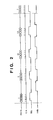
- FIG. 14 is a circuit diagram showing a specific example of a circuit arrangement for time-divisionally driving printing elements, in units of blocks, which perform printing by using heat.
- FIG. 15 is a timing chart of signals input to the circuit in FIG. 14 .
- reference numeral 1 denotes an electrothermal transducer such as a heater provided for each printing element; 2 , a functional element such as a transistor or FET for controlling the energization state of each electrothermal transducer; 3 , an AND circuit for outputting a control signal for each functional element; 5 , a decoder; 9 , a power supply line; 10 , a ground line; 13 , a shift register, and 14 , a latch.
- Reference symbol CLK denotes a clock signal; DATA, an image data signal; LAT, a latch pulse; BENB, a block selection signal; and ENB, a driving pulse signal.
- Time-divisional driving can be performed by sequentially activating the block selection signals BENB within a period of the latch pulse signal LAT. In this case, if the block selection signals BENB are distributedly connected to printing elements, distributed driving is performed.
- a printing apparatus having various printing modes uses a method of changing the pattern of the block selection signals BENB to be input to the decoder 5 within a period of the latch pulse signal LAT in accordance with a printing mode.
- printing elements can be driven in various patterns by combining other control signals.
- the number of printing elements arranged in the printhead increases, and the density of printing elements also increases. For this reason, the number of blocks in the above time-divisional driving method increases, and the number of control signal lines increases even with the use of decoder circuits and the like. This tendency is typical when the driving pattern is changed in accordance with a printing mode.
- the transfer clocks for image data are also speeded up. This is because image data corresponding to all the printing elements on the printhead must be transferred within a period of a latch pulse.
- a printhead circuit like the one described above is often manufactured as one chip-like heater board (H. B.) by using a semiconductor manufacturing process. If, however, the transfer clock for image data is set to 10 MHz or more, the buffer size in the integrated circuit increases owing to high-speed transfer, although it depends on the semiconductor design rule.
- printheads having a print width of 1 inch become increasingly popular than those having a print with of 0.5 inches.
- a printhead with 300 nozzles/inch if it takes 0.1 ⁇ s (10 MHz) per pixel, a time t required to transfer 1-line image data for the printhead is given by
- this time greatly influences the driving period of each printing element.
- the period until the start of image data transfer of the next line must be shorter than the above time.
- a technique of shifting data at both the leading edge and trailing edge of a clock is implemented. In this case as well, image data must be transferred to the printhead at a high speed.
- the driving speed of each printing element is decreased in inverse proportion to an increase in the number of printing elements.
- a method of dividing a printing element array into a plurality of portions, and using a plurality of input lines for image data is available. This method is implemented for an elongated printhead of a full-line type and the like. However, several to ten-odd image data input lines must be prepared in accordance with the number of nozzles of the printhead. With this arrangement, driving circuits with different specifications must be designed again for the respective printheads with different specifications.
- connection terminals between the printhead and the printing apparatus body increases, causing various problems. For example, the cost of the connector portions of the printhead and apparatus body increases, and contact failures occur at connection portions. In an ink-jet printing apparatus, an operation error may be caused when ink adheres to the connector portions.
- a printhead comprises a plurality of printing elements for printing, a block selection circuit for outputting a selection signal for selecting a block of a plurality of printing elements that can be simultaneously driven, a printing control circuit for outputting a driving signal for selectively driving the printing elements, together with the selection signal, to each of the printing elements in correspondence with image data, and input means for receiving external image data to be input to the printing control circuit, wherein the input means is adapted to receive the image data and block selection data input to the block selection circuit in a bus format of a plurality of consecutive bits.
- a printhead comprises a plurality of printing elements for printing, a block selection circuit for outputting a selection signal for selecting a block of a plurality of printing elements that can be simultaneously driven, a printing control circuit for outputting a driving signal for selectively driving the printing elements, together with the selection signal, to each of the printing elements in correspondence with image data, and input means for receiving external image data to be input to the printing control circuit, wherein the input means is adapted to receive the image data in a bus format of a plurality of bits.
- a printhead comprises a plurality of printing elements for printing, a block selection circuit for outputting a selection signal for selecting a block of a plurality of printing elements that can be simultaneously driven, a printing control circuit for outputting a driving signal for selectively driving the printing elements, together with the selection signal, to each of the printing elements in correspondence with image data, and input means for receiving external image data to be input to the printing control circuit, wherein the input means is adapted to receive data associated with a printing element driving timing continuously with the image data.
- the circuit arrangement can be simplified as compared with the prior art, and transfer of image data, control signals, and the like from the printing apparatus body can be speeded up with a smaller number of signal lines.
- the number of contacts such as connector portions of the printhead is decreased, the cost of connectors and the connection failures are reduced, resulting in an improvement in reliability.
- a printhead capable of high-density, high-speed printing can be provided by increasing the number of printing elements or arraying printing elements in various patterns without changing the size and cost of the printhead.
- a printing apparatus includes the printhead of the present invention, a color printer capable of high-density, high-speed printing can be implemented at a low cost.
- Still another object of the present invention can be achieved by a driving method for the above printhead.
- Still another object of the present invention can be achieved by a data output apparatus for outputting data corresponding to the printhead described above.
- FIG. 1 is a block diagram showing the circuit arrangement of a printhead according to the first embodiment of the present invention
- FIG. 2 is a timing chart showing the state of each signal in the circuit in FIG. 1;
- FIG. 3 is a block diagram showing the circuit arrangement of a printhead according to the second embodiment of the present invention.
- FIG. 4 is a detailed block diagram showing the flow of internal signals in part of the circuit in FIG. 3;
- FIG. 5 is a timing chart showing the state of each signal in the circuit in FIG. 4;
- FIG. 6 is a timing chart showing the state of each signal in the circuit in FIG. 3;
- FIG. 7 is a block diagram showing the circuit arrangement of a printhead according to the third embodiment of the present invention.
- FIG. 8 is a detailed block diagram showing the flow of internal signals in the circuit in FIG. 7;
- FIG. 9 is a timing chart showing the state of each signal in the circuit in FIG. 8;
- FIG. 10 is a block diagram showing the circuit arrangement of a printhead according to the fourth embodiment of the present invention.
- FIG. 11 is a timing chart showing the state of each signal in the circuit in FIG. 10;
- FIG. 12 is a block diagram showing the circuit arrangement of a printhead according to the fifth embodiment of the present invention.
- FIG. 13 is a timing chart showing the state of each signal in the circuit in FIG. 12;
- FIG. 14 is a block diagram showing the circuit arrangement of a conventional printhead
- FIG. 15 is a timing chart showing the state of each signal in the circuit in FIG. 14;
- FIG. 16 is a block diagram showing a control configuration for an overall printing apparatus using a printhead of the present invention.
- FIG. 17 is a block diagram showing the first arrangement example of the printhead control portion of the printing apparatus using the printhead of the present invention.
- FIG. 18 is a block diagram showing the second arrangement example of the printhead control portion of the printing apparatus using the printhead of the present invention.
- FIG. 19 is a block diagram showing the third arrangement example of the printhead control portion of the printing apparatus using the printhead of the present invention.
- FIGS. 20A to 20 C are exploded perspective views showing the mechanical arrangement of the printhead of the present invention.
- FIG. 21 is a perspective view showing the mechanical arrangement of the printing apparatus using the printhead of the present invention.
- FIG. 1 is a block diagram showing the basic circuit arrangement of a printhead according to the first embodiment of the present invention.
- reference numeral 1 denotes a printing element including an electrothermal transducer.
- printing elements are one-dimensionally arranged; they are arrayed in a predetermined direction throughout the print width, as shown in FIG. 1 .
- Reference numeral 2 denotes a driver for driving a printing element. Each driver 2 is connected to a corresponding electrothermal transducer. Referring to FIG. 1, each driver 2 is indicated by the electrical symbol of a transistor. However, another element such as an FET can be used as long as it is a functional element for controlling a conductive state.
- Reference numeral 3 denotes an AND circuit which determines a driving condition for a corresponding printing element and is provided for each printing element; 4 , a latch circuit; 5 , a decoder; 6 and 7 , AND circuits; 9 , a power supply line; and 10 , a ground line.
- a combination of one printing element 1 , one driver 2 , and one AND circuit 3 will be referred to as a segment hereinafter.
- a portion 8 constituted by a plurality of latches will be referred to as the first printing control unit, and a portion constituted by the latch circuit 4 and decoder 5 will be referred to as the second printing control unit.
- image data signal DATA is supplied in a 4-bit bus format, and block selection data is continuously contained in the head of image data.
- the image data signal DATA is separated by the selection signal SEL; the data for block selection is supplied to the decoder 5 , and the image data is supplied to each first printing control unit.
- image data and block selection data exemplify the data in a 4-bit bus format as a multi-bit bus format.
- the present invention is not limited to this, and an 8-bit bus format or the like may be used.
- image data and data for block selection are continuously supplied.
- the word “continuously” used in each embodiment of the present invention includes not only a case where data are directly continuous with each other but also a case where data are serially transferred in a single signal line even if a non-signal period or other data strings are interposed between data.
- the first printing control unit 8 serves as a shift register whose data can be updated for each block.
- FIG. 1 shows only a circuit for 16 segments corresponding to the first block.
- the printhead of this embodiment is therefore adapted to control 256 printing elements at maximum.
- Each printing control unit can be arbitrarily set in the individual selection mode or block selection mode.
- selected printing elements can be arbitrarily arranged; they may be arrayed in conformity with an image process in the printing apparatus. By increasing the number of decoder blocks or the number of shift registers in each driven block, more than 256 printing elements can be driven.
- the AND circuits 6 and 7 serve to branch a clock line. If the allocation of shift registers and data is determined, these circuits need not be used. As will be described later, an input to this branch circuit can also be used as a latch signal for a shift register.
- FIG. 2 is a timing chart showing the state of each signal in the circuit block of FIG. 1 . The operation of the circuit in FIG. 1 will be described below with reference to this timing chart.
- each first printing control unit decodes 4-bit parallel data from the image data signal DATA input in the 4-bit bus format into a base-16 signal (hexadecimal number), whereas each second printing control unit decodes four binary data into base-16 signals (hexadecimal numbers).
- block selection data for the second printing control unit is input to image data signal DATA [3..0] terminals and latched by CLK. At this time, the selection signal SEL is OFF, and hence the block selection data is held in the decoder 5 .
- the selection signal SEL is then enabled to perform switching to input a clock to each first printing control unit.
- Image data encoded into hexadecimal numbers in units of four bits, e.g., “4”, “7”, “A”, and “3”, are sequentially input to the first printing control units and shifted by synchronous clock signals CLK.
- CLK synchronous clock signals
- the driving pulse signal ENB is made active until the next clock signal CLK is input. With this operation, the 16 printing elements 1 from R 1 to R 16 are simultaneously driven in accordance with the corresponding image data.
- This processing is repeated for the 16 blocks to drive the 256 printing elements.
- the circuit arrangement can be simplified, and the number of components can be reduced.
- the driving circuit can be formed by a semiconductor manufacturing process on the same substrate as the substrate on which printing elements and the like are arranged. This makes it possible to attain reduction in the size and cost of a printhead while maintaining its functions.
- the number of connection terminals can be decreased, and an increase in the number of printing elements can be handled without changing the number of terminals. If, therefore, the printhead of this embodiment is mounted in a printing apparatus, control on the printhead on the apparatus body side can be simplified.
- FIG. 3 is a circuit diagram showing the arrangement of the printhead according to the second embodiment of the present invention.
- the same reference numerals as in the first embodiment denote the same parts in the second embodiment, and a detailed description thereof will be omitted.
- the arrangements of printing elements and functional elements for driving them are the same as those in the first embodiment, but the layout of printing elements and block arrangement are designed to drive more printing elements without increasing the number of signal lines.
- the printhead of this embodiment has 352 printing elements ⁇ 2 rows, i.e., a total of 704 printing elements, and can drive the printing elements in the respective rows under different conditions.
- the printing elements in one row are grouped into eight blocks, and codes 0 to 8 are assigned to the respective blocks. Odd- and even-numbered printing elements are respectively driven at different timings in accordance with image data corresponding to the 44 printing elements belonging to a block corresponding to each code.
- the printhead includes, for each of two rows, an arrangement comprised of 352 printing elements 1 , a driver block 2 for driving the printing elements in one row, AND circuits 3 for determining driving conditions for the respective printing elements, a 3/8 coder 5 for decoding a code for designating a block, a 3-bit latch 4 ′ for holding a 3-bit signal input to the decoder, a 4-bit shift register 4 for sequentially holding input 4-bit data signals, a 44-bit latch 8 ′ for holding printing data for the 44 printing elements in a block, and a 4 ⁇ 11-bit shift register 8 for sequentially holding 11 input 4-bit data signals.
- VH denotes a power supply line for supplying a printing current to each printing element 1 ;
- GNDH a printing current ground conductive line;
- VDD a power supply line for a logic circuit, and
- GNDL a ground conductive member. Both printing current ground conductive line GNDH and ground conductive member GNDL are connected to a semiconductor substrate SUB.
- Control signals input to the printhead of this embodiment include four data signal lines DATA 0 to DATA 3 , a clock signal CLK, a latch signal LATN for defining a driving period, and four driving signals OHE 1 N, EHE 1 N, OHE 2 N, and EHE 2 N corresponding to the odd- and even-numbered printing elements in each row.
- Image data and block selection data (codes) continuously transferred over a 4-bit data bus are internally separated and used.
- FIG. 4 is a view showing the circuit arrangement for generating control signals in the circuit shown in FIG. 3 .
- FIG. 5 is a timing chart showing the relationship between input control signals and printing control signals generated in the circuit.
- the data transfer clock CLK shifts at leading and trailing edges at 10 MHz. This makes it possible to double the transfer speed.
- Each of the signals e 0 to e 7 can simultaneously activate 44 distributed printing elements. This signal is used as the first printing control signal. As shown in FIG. 3, the printing elements belonging to the block designated by the signal e 0 are those indicated by Seg numbers 1 , 2 , 17 , 18 , . . . . The printing elements belonging to the block designated by the signal e 1 are those indicated by Seg numbers 3 , 4 , 19 , 20 , . . . .
- the second printing control signal generated in the circuit includes BLK outputs B 0 to B 43 .
- Each output can simultaneously activate eight printing elements.
- the output B 0 controls the printing elements indicated by Seg numbers 1 , 3 , 5 , 7 , . . . , 15
- the output B 1 controls the printing elements indicated by Seg numbers 2 , 4 , 6 , 8 , . . . , 16 .
- the 352 ⁇ 2 (rows) printing elements connected to the two blocks can be arbitrarily turned on/off.
- printing control data can be transferred to the printhead at a high speed.
- printing control data for the two printhead rows are continuously input to DATA [3..0] terminals. Note that since block designation data input to the 3/8 coder 5 in this embodiment consists of 3 bits, one bit of DATA 3 is masked. If, however, the number of divided blocks or printing elements increases, this signal can also be used.
- FIG. 6 is a timing chart for driving all the printing elements shown in FIG. 3 .
- BLK data corresponding to one output ENB 1 from the coder circuit is transferred to the DATA line and held by the latch signal LATN.
- the next printing control data is input.
- driving signals to be converted into printing energies are input. As described above, these signals correspond to odd- and even-numbered printing elements (OH 1 N/EHE 1 N), and are input for each printing element row (OHE 1 N, EHE 1 N/OHE 2 N, EHE 2 N).
- each printing element includes an electrothermal transducer
- the printing density or dot shape can be changed by inputting a signal upon changing its pulse width.
- odd- and even-numbered printing elements can be driven by inputting signals to them while the pulse width of each signal is divided into a pre-pulse and main pulse.
- a halt period is set between a pre-pulse and a main pulse, as shown in FIG. 6.
- a scheme of inserting a pre-pulse for another terminal in this halt period is also known.
- the arrangement capable of separately controlling odd- and even-numbered printing elements can cope with various printhead driving schemes. Since the above interlaced driving scheme can shorten the pulse input period while preventing adjacent printing elements from being simultaneously turned on, the time required to drive all the printing elements can be substantially shortened.
- the printhead of this embodiment can be manufactured with all the above printing elements and driving circuits being mounted on a semiconductor circuit board.
- the printing elements in the two rows may be arranged in a staggered form to increase the printing density, or the printing elements on one side may be used for monochrome printing while those on the other side are used for color printing.
- the printing elements may be arranged in accordance with the above divisional driving pattern to physically cope with time differences in driving.
- data signals input from the 4-bit data bus are converted into the first and second printing control signals and used.
- the latch circuits are used to hold the respective bits transferred over the data bus so as to hold the data of the first and second control signals until the next data updating operation after the data transfer.
- This method produces a time margin in inputting a driving signal to be converted into printing energy. If a printhead having 600 or more printing elements is driven at a printing frequency of 10 kHz or more, since the number of divided blocks increases as well, such a time margin cannot be produced.
- a characteristic feature of this embodiment is that even if such many printing elements are arranged in a plurality of rows, printing control data can be transferred over a single bus. In addition, the data transfer time can be minimized with respect to the printing period.
- control inputs capable of separately driving even- and odd-numbered printing elements are set for the respective printing element rows.
- printing elements to be selected by ENB can also be set on each printing element row for every several pixels. In this case, for the sake of descriptive convenience, adjacent printing elements belong to the same block.
- a bit input to the decoder circuit for DATA 3 is masked.
- the current number of printing elements grouped can be doubled by only adding data to this portion from the printing apparatus. That is, a characteristic feature of this embodiment is that the number of printing elements controlled can be doubled without changing the transfer speed.
- This arrangement for printing control data transfer can cope with various types of printheads. This makes it possible to greatly reduce the developing/manufacturing cost for this apparatus and produce a great merit in terms of a printhead.
- High-speed data transfer and a reduction in printing energy application time realized by the specific driving method of this embodiment can produce a time margin on the printing apparatus side where the printhead is driven.
- a printhead according to the third embodiment of the present invention will be described below.
- the circuit arrangement shown in FIGS. 3 and 4 of the second embodiment is adapted to receive the image data and the block selection data (code) which are positioned alternately.
- the circuit arrangement shown in FIGS. 3 and 4 is improved so that the kind of data is easily known by making the arrangement to collect the image data group and the block selection data group and to transfer them in group.
- FIG. 7 Such a circuit arrangement of this embodiment on the semiconductor substrate for the printhead is shown in FIG. 7 .
- the arrangement shown in FIG. 7 differs from the arrangement shown in FIG. 3, in the layout of the 4-bit shift register for receiving the block selection data, in the shift register 8 for receiving the image data, and in the number of printing elements 1 .
- the other basic arrangement shown in FIG. 7 is similar to that of FIG. 3 .
- FIG. 8 shows a detailed circuit arrangement in part of the semiconductor substrate for the printhead. Similar to FIG. 7, the arrangement shown in FIG. 8 differs from the arrangement shown in FIG. 4, in the layout of the 4-bit shift register for receiving the block selection data, in the shift register 8 for receiving the image data, and in the number to printing elements 1 . However, the other basic arrangement shown in FIG. 8 is similar to that of FIG. 4 . And timings of the data transfer are shown in FIG. 9 .
- circuit shown in FIG. 7 it is also possible to arrange the circuit shown in FIG. 7 to allocate the circuits for upper bits and lower bits on respective shorter sides of the semiconductor substrate (not shown).
- wiring length on the substrate is advantageously shortened, thereby miniaturizing the size of the semiconductor substrate.
- FIG. 10 is a block diagram showing the arrangement of the printhead according to the fourth embodiment of the present invention.
- the same reference numerals as in the first embodiment denote the same parts in the fourth embodiment, and a detailed description thereof will be omitted.
- the arrangements of printing elements and functional elements for driving them are the same as those in the first embodiment.
- the connection arrangement of the printing elements is similar to that in the second embodiment.
- reference numerals 4 and 8 denote latch circuits for holding block selection data input to a common data bus (line) DATA and encoded image data.
- the latches 4 and 8 function as shift registers capable of updating the driven block selection data and encoded image data in units of blocks.
- One output signal from the shift register 8 can simultaneously activate 16 consecutive printing elements. This signal is used as the first printing control signal; output 1 is made to correspond to R 1 to R 16 , and output 2 is made to correspond to R 17 to R 32 , i.e., 16 printing elements.
- the latch 4 and decoder 5 output the second printing control signal for controlling printing elements to be simultaneously turned on within a block. If, for example, the shift register 4 is capable of handling 4-bit data, 16 printing elements can be controlled at maximum.
- Output 1 from this decoder circuit is connected in correspondence with R 1 , R 17 , R 33 , R 49 , . . . of printing elements 1
- output 2 is connected in correspondence with R 2 , R 18 , R 34 , R 50 , . . . of the printing elements 1 .
- a block of printing elements to be simultaneously driven is selected by the second printing control signal, and specific printing elements in this printing element group which are to be turned on can be arbitrarily selected by the first printing control signal.
- the printing elements of the printhead of this embodiment can be driven/controlled up to 256 printing elements.
- Table 1 below shows the connection arrangement of the printing elements in this embodiment.
- the numerals in the column represent the numbers of printing elements R that are consecutively arranged
- the numerals in the row represent the numbers of signals output from the latch 4 and decoder 5 .
- Each output signal from the printing control unit 8 can activate all printing elements within the bold-line frame in the table (e.g., from R 1 to R 16 ). While blocks are selected by the second printing control signals from the latch 4 and decoder 5 , the printing elements in each block are separately selected by outputs from the printing control unit 8 , thereby arbitrarily energizing all the 256 printing elements.
- each printing control unit can be arbitrarily set in the individual selection mode or block selection mode.
- selected printing elements can be arbitrarily arranged; they may be arrayed in conformity with an image process in the printing apparatus.
- FIG. 11 is a timing chart showing the state of each signal in the circuit block of FIG. 10 .
- only one DATA signal line is used.
- the above encoded data for the respective printing control units are input and shifted by CLK.
- the decoder 5 and first printing control unit 8 respectively hold block selection data and data for selecting a printing element block.
- the printing elements R 1 , R 17 , R 33 , . . . , belonging to the first block of the printing elements R 1 to R 256 are simultaneously energized in accordance with the image data.
- all the 256 printing elements 1 in the printhead of this embodiment can be driven.
- the printing elements R 16 , R 32 , R 48 , . . . are activated, and printing currents are simultaneously supplied to them for a period of time corresponding to the pulse width input to the ENB signal.
- the circuit arrangement can be simplified, and the chip size can be reduced.
- the number of control signals (terminals) is three.
- data is transmitted over a bus, and a further increase in transfer rate can be attained.
- a printhead used for serial printing for example, a printhead having a printing density of 600 dpi and about 300 to 600 printing elements is expected to be generally used in the future. There is a merit in setting the number of connection terminals connected to the printing apparatus body to be smaller than that in the prior art as in this embodiment.
- a scheme of transferring data signals over a bus to realize high-speed transfer can be effectively used.
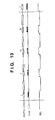
- FIG. 12 is a block diagram showing the arrangement of a printhead according to the fifth embodiment of the present invention.
- the same reference numerals as in the fourth embodiment denote the same parts in the fifth embodiment, and a detailed description thereof will be omitted.
- input signals for applying driving energy to printing elements 1 are also used as latch signals.
- the circuit arrangement shown in FIG. 12 is almost the same as that shown in FIG. 10 except that latches 11 and 12 are additionally used to temporarily hold data in shift registers 4 and 8 .
- the ENB signals for applying driving energy like those described above are not used, and SEL signals also serving as latch signals are used.
- the number of input signals is three, which is equal to the number of terminals.
- AND circuits 6 and 7 are used to sort signals input from the DATA terminal into driving control data and driving energy signals in accordance with the states of signals input form the SEL terminal. With this arrangement, signals input from the ENB terminal can also be used as signal input from the DATA terminal.
- FIG. 13 is a timing chart showing the state of each signal in the circuit of this embodiment.
- the SEL signal is ON
- control data corresponding to image data is input from the DATA terminal in synchronism with CLK and held in the latches 11 and 12 to select printing elements to be driven.
- the SEL signal is OFF
- pulses corresponding to driving energy signals from the DATA terminal are input to drive the printing elements. That is, data associated with the driving timing of printing elements are input from the DATA terminal continuously with respect to the image data, and a length of time (period of time) during which the printing elements are driven can be set in accordance with the pulse width of the data (signal) associated with this driving timing.
- different driving energy signals can also be sent out from the printing apparatus side in units of blocks.
- the pulse width of a driving energy signal can be changed.
- the pulse width can be changed in accordance with the number of printing elements in a block which are simultaneously turned on.
- grayscale printing data may be used to print an area corresponding to one pixel with a plurality dots.
- this technique can be reflected in the above embodiment.
- grayscale printing can be performed by transferring grayscale data over the data bus upon encoding the data.
- this embodiment can use a technique of inputting data having a pulse width to the printhead upon encoding it, and generating a pulse having a width corresponding to the code inside the printhead.
- Such signal input methods can be arbitrarily set on the basis of the arrangements of a printhead and printing apparatus. Many methods depend on an image processing method for a printhead, in particular, and the layout of printing elements and correspondence with blocks are based on this. Therefore, an arrangement is preferably set such that whether to transfer a printing control signal at a high speed or temporarily hold it by using a latch circuit is determined, in inputting the printing control signal, on the basis of the number of printing elements to be simultaneously driven or block intervals.
- the present invention provides an arrangement capable of inputting printing control signals for the printhead regardless of the number of printing elements. That is, by encoding (converting) an input signal, obtained by bit-mapping an image to be printed into raster data, into a multilevel signal and using it as a printing control signal, printhead control can be simplified, and high performance can be realized.
- an integrated circuit for arbitrating printing control signals is mounted on a carriage on which the printhead is mounted, information for the printhead can be communicated as well as printing control signals.
- the function of checking a temperature sensor and the like on the printhead can be encoded, and the resultant register value is mapped on the integrated circuit.
- an image data pattern or grayscale printing data can be encoded and the timing of feedback control for them can be encoded.
- a circuit on the printhead is preferably capable of directly handling these encoded data to directly convert the data into driving control data for printing elements.
- a printhead is disclosed in Japanese Patent Laid-Open No. 8-108550, which has an arrangement in which a circuit for the printhead like the one disclosed in this embodiment is mounted as a semiconductor integrated circuit on a substrate on which printing elements are arranged or is integrally formed in the same substrate as the substrate on which printing elements are arranged.
- a printhead may incorporate a portion of the above circuit arrangement, e.g., a decoder, as an arrangement outside a substrate. If, however, the above circuit is formed as a substrate (element substrate) for the printhead of the present invention, printing control on printing elements is complete. This makes it possible to form a high-performance printhead with a simple arrangement. In this case, since the number of terminals connected to the carriage on which the printhead is mounted can be minimized, a printing apparatus with high reliability can be provided.
- FIGS. 20A to 20 C are exploded perspective views showing the mechanical arrangement of an ink-jet printhead to which the circuit arrangement of the printhead of the above embodiment is applied.
- Heating resistors 112 serving as electrothermal transducers forming printing elements are formed on an element substrate 101 formed by integrating the above circuit arrangement shown in FIG. 17 with a silicon substrate or the like.
- Channels 111 surround the resistors and extend toward the two sides of the substrate.
- a resin such as a dry film, SiN, or the like can be used as a material for these channels.
- An orifice plate 102 shown in FIG. 20A has a plurality of orifices 121 at positions to oppose heating resistors 112 and is joined to the member forming the channels.
- a wall member 103 shown in FIG. 20C is used to from a common liquid chamber for supplying ink. Ink is supplied from this common liquid chamber to each channel through an end portion of the element substrate 101 .
- connection terminals 113 for receiving external data and signals are formed on two sides of the element substrate 101 .
- FIG. 21 is a perspective view showing the outer appearance of a printing apparatus as a typical embodiment for performing printing by using the printhead of the present invention.
- a carriage HC engages with a spiral groove 5004 of a lead screw 5005 , which rotates via driving force transmission gears 5009 to 5011 upon forward/reverse rotation of a driving motor 5013 .
- the carriage HC has a pin (not shown), and is reciprocally scanned in the directions of arrows a and b in FIG. 21 .
- An integrated ink-jet cartridge IJC which incorporates a printing head IJH and an ink tank IT is mounted on the carriage HC.
- Reference numeral 5002 denotes a sheet pressing plate, which presses a paper sheet against a platen 5000 , ranging from one end to the other end of the scanning path of the carriage.
- Reference numerals 5007 and 5008 denote photocouplers which serve as a home position detector for recognizing the presence of a lever 5006 of the carriage in a corresponding region, and used for switching, e.g., the rotating direction of the motor 5013 .
- Reference numeral 5016 denotes a member for supporting a cap member 5022 , which caps the front surface of the printing head IJH; and 5015 , a suction device for sucking ink residue through the interior of the cap member.
- the suction device 5015 performs suction recovery of the printing head via an opening 5023 of the cap member 5015 .
- Reference numeral 5017 denotes a cleaning blade; 5019 , a member which allows the blade to be movable in the back-and-forth direction of the blade. These members are supported on a main unit support plate 5018 .
- the shape of the blade is not limited to this, but a known cleaning blade can be used in this embodiment.
- Reference numeral 5021 denotes a lever for initiating a suction operation in the suction recovery operation.
- the lever 5021 moves upon movement of a cam 5020 , which engages with the carriage, and receives a driving force from the driving motor via a known transmission mechanism such as clutch switching.
- the capping, cleaning, and suction recovery operations are performed at their corresponding positions upon operation of the lead screw 5005 when the carriage reaches the home-position side region.
- the present invention is not limited to this arrangement as long as desired operations are performed at known timings.
- FIG. 16 is a block diagram showing the arrangement of a control circuit of the printing apparatus.
- reference numeral 1700 denotes an interface for inputting a printing signal from an external unit such as a host computer; 1701 , an MPU; 1702 , a ROM for storing a control program executed by the MPU 1701 ; and 1703 , a DRAM for storing various data (the printing signal, printing data supplied to the printing head, and the like).
- Reference numeral 1704 denotes a gate array (G.A.) for performing supply control of printing data to the printing head IJH.
- G.A. gate array
- the gate array 1704 also performs data transfer control among the interface 1700 , the MPU 1701 , and the RAM 1703 .
- Reference numeral 1709 denotes a carrier motor for transferring the printing head IJH in the main scanning direction; and 1708 , a transfer motor for transferring a printing sheet.
- Reference numeral 1705 denotes a head driver for driving a head; and 1706 and 1707 , motor drivers for driving the transfer motor 1708 and the carrier motor 1709 .
- the printing signal is converted into printing data for a printing operation between the gate array 1704 and the MPU 1701 .
- the motor drivers 1706 and 1707 are driven, and the printing head is driven in accordance with the printing data supplied to the head driver 1705 , thus performing the printing operation.
- FIG. 17 is a block diagram showing the first arrangement example to explain communication between the head control unit and the printhead in FIG. 16 .
- a gate array 1704 is used to control printing data supplied from an interface 1700 .
- a characteristic feature of this arrangement is that the function of this gate array is implemented by a raster image control unit 1720 as much as possible.
- reference numeral 1719 denotes a carriage on which a printhead 1726 is mounted; 1720 , a raster image control unit for controlling the transfer of image data in a raster form; 1721 , an encoder for reading carriage position information; 1722 , a power supply; and 1723 and 1724 , connection portions having connection terminals.
- a conventional printing apparatus uses a technique of inputting image data bit-mapped by printer driver software to the interface 1700 of the printing apparatus and further bit-mapping the data in accordance with the arrangement of the printhead (printing element array) using the gate array 1704 . For this reason, a memory 1703 for storing raster data is frequently accessed, resulting in a decrease in printing speed.
- encoded printing control data are sequentially transferred to the printhead of the present invention, these processes can be sped up, and the throughput can be improved.
- Signal lines containing encoded data generated by the raster image control unit 1720 are directly connected to the printhead 1726 via the connection portions 1723 and 1724 .
- position detection data is obtained by the encoder 1721 .
- This information serves as a sync signal in sending out a printing control signal.
- the raster image control unit 1720 can also communicate with the power supply 1722 for supplying power to the printhead under the control of the gate array 1704 .
- FIG. 18 shows the second arrangement example of the printing apparatus with the printhead according to the present invention. This example is almost the same as the first arrangement example shown in FIG. 17 except that a gate array 1725 for arbitration is mounted on the carriage side on which the printhead is mounted.
- the arrangement of the raster image control unit 1720 can further be simplified because all printing control signals can be encoded. More specifically, signals may be transmitted to a carriage 1719 according to a communication protocol set between the raster image control unit 1720 and the gate array 1725 . This makes it possible to greatly decrease the number of terminals of the connection portions 1723 and 1724 .
- a communication protocol may be uniquely set for the printing apparatus or an existing communication protocol may be applied without any modification. Since the gate array 1725 is mounted on the carriage 1719 , the data communication speed does not depend on the circuit arrangement of a printhead 1726 , and communication can be performed at a higher speed. In addition, for a serial type printhead with a print width of about 1 ⁇ 2 to 1 inch, if data are encoded, satisfactory results can be obtained even by communication at the same transfer rate as in the prior art.
- Communications with the gate array 1725 can be classified into transmission of encoded raster image data during printing and transmission of a printhead information request command/reception of feedback data, which enables feedback control on a sensor and the like of the printhead 1726 . If these communications are performed according to an existing sequence, complicated feedback control on the printhead can be simplified. In this case, adding a command register will facilitate processing in the printing apparatus body. Since a communication protocol is determined, an additional function can be easily recognized.
- FIG. 19 is a view showing the third arrangement example of the printing apparatus using the printhead according to the present invention.
- communication between the connection portions 1723 and 1724 is performed by radio, and no substantial contact portion is provided except for the supply of power.
- infrared communication or the like is available. More specifically, radio communication can be implemented by using infrared emitting and receiving elements as the connection portions 1723 and 1724 .
- signal terminals can be integrated into one system by encoding all control signals for the printhead.
- a high-performance printing apparatus can be provided by using an existing infrared communication protocol or another radio communication protocol as this communication protocol.
- the scheme of performing printing control on the basis of a communication protocol will greatly influence the forms of future printing apparatuses. More specifically, by encoding printing control signals, the substantial number of connection terminals between the printing apparatus body and the printhead can be reduced, and high-speed data transfer can be implemented. This makes it possible to reduce the communication load and further simplify the arrangement of the apparatus as a direct printer. Since communication protocols that define higher transfer rates have increased in number, the processing speed of a printing apparatus can be effectively increased by using this communication method.
- droplets discharged from the printing head are ink droplets, and a liquid stored in the ink tank is ink.
- the liquid to be stored in the ink tank is not limited to ink.
- a treatment solution to be discharged onto a printing medium so as to improve the fixing property or water resistance of a printed image or its image quality may be stored in the ink tank.
- a printer which comprises means (e.g., an electrothermal transducer, laser beam generator, and the like) for generating heat energy as energy utilized upon execution of ink discharge, and causes a change in state of an ink by the heat energy, among the ink-jet printers.
- means e.g., an electrothermal transducer, laser beam generator, and the like
- heat energy as energy utilized upon execution of ink discharge
- the system is effective because, by applying at least one driving signal, which corresponds to printing information and gives a rapid temperature rise exceeding nucleate boiling, to each of electrothermal transducers arranged in correspondence with a sheet or liquid channels holding a liquid (ink), heat energy is generated by the electrothermal transducer to effect film boiling on the heat acting surface of the printing head, and consequently, a bubble can be formed in the liquid (ink) in one-to-one correspondence with the driving signal.
- the driving signal is applied as a pulse signal, the growth and shrinkage of the bubble can be attained instantly and adequately to achieve discharge of the liquid (ink) with the particularly high response characteristics.
- signals disclosed in U.S. Pat. Nos. 4,463,359 and 4,345,262 are suitable. Note that further excellent printing can be performed by using the conditions described in U.S. Pat. No. 4,313,124 of the invention which relates to the temperature rise rate of the heat acting surface.
- the arrangement using U.S. Pat. Nos. 4,558,333 and 4,459,600 which disclose the arrangement having a heat acting portion arranged in a flexed region is also included in the present invention.
- the present invention can be effectively applied to an arrangement based on Japanese Patent Laid-Open No. 59-123670 which discloses the arrangement using a slot common to a plurality of electrothermal transducers as a discharge portion of the electrothermal transducers, or Japanese Patent Laid-Open No. 59-138461 which discloses the arrangement having an opening for absorbing a pressure wave of heat energy in correspondence with a discharge portion.
- a full line type printing head having a length corresponding to the width of a maximum printing medium which can be printed by the printer, either the arrangement which satisfies the full-line length by combining a plurality of printing heads as disclosed in the above specification or the arrangement as a single printing head obtained by forming printing heads integrally can be used.
- an exchangeable chip type printing head as described in the above embodiment, which can be electrically connected to the apparatus main unit and can receive an ink from the apparatus main unit upon being mounted on the apparatus main unit but also a cartridge type printing head in which an ink tank is integrally arranged on the printing head itself can be applicable to the present invention.
- recovery means for the printing head, preliminary auxiliary means, and the like provided as an arrangement of the printer of the present invention since the printing operation can be further stabilized.
- examples of such means include, for the printing head, capping means, cleaning means, pressurization or suction means, and preliminary heating means using electrothermal transducers, another heating element, or a combination thereof. It is also effective for stable printing to provide a preliminary discharge mode which performs discharge independently of printing.
- a printing mode of the printer not only a printing mode using only a primary color such as black or the like, but also at least one of a multi-color mode using a plurality of different colors or a full-color mode achieved by color mixing can be implemented in the printer either by using an integrated printing head or by combining a plurality of printing heads.
- the ink is a liquid.
- the present invention may employ an ink which is solid at room temperature or less and softens or liquefies at room temperature, or an ink which liquefies upon application of a use printing signal, since it is a general practice to perform temperature control of the ink itself within a range from 30° C. to 70° C. in the ink-jet system, so that the ink viscosity can fall within a stable discharge range.
- an ink which is solid in a non-use state and liquefies upon heating may be used.
- an ink which liquefies upon application of heat energy according to a printing signal and is discharged in a liquid state, an ink which begins to solidify when it reaches a printing medium, or the like, is applicable to the present invention.
- an ink may be situated opposite electrothermal transducers while being held in a liquid or solid state in recess portions of a porous sheet or through holes, as described in Japanese Patent Laid-Open No. 54-56847 or 60-71260.
- the above-mentioned film boiling system is most effective for the above-mentioned inks.
- the present invention can be applied to a system constituted by a plurality of devices (e.g., host computer, interface, reader, printer) or to an apparatus comprising a single device (e.g., copying machine, facsimile machine).
- devices e.g., host computer, interface, reader, printer
- apparatus comprising a single device (e.g., copying machine, facsimile machine).
- the object of the present invention can also be achieved by providing a storage medium storing program codes for performing the aforesaid processes to a computer system or apparatus (e.g., a personal computer), reading the program codes, by a CPU or MPU of the computer system or apparatus, from the storage medium, then executing the program.
- a computer system or apparatus e.g., a personal computer
- the program codes read from the storage medium realize the functions according to the embodiments, and the storage medium storing the program codes constitutes the invention.
- the storage medium such as a floppy disk, a hard disk, an optical disk, a magneto-optical disk, CD-ROM, CD-R, a magnetic tape, a non-volatile type memory card, and ROM can be used for providing the program codes.
- additional functions according to the above embodiments are realized by executing the program codes which are read by a computer.
- the present invention includes a case where an OS (operating system) or the like working on the computer performs a part or an entire process in accordance with designations of the program codes and realizes functions according to the above embodiments.
- the present invention also includes a case where, after the program codes read from the storage medium are written in a function expansion card which is inserted into the computer or in a memory provided in a function expansion unit which is connected to the computer, a CPU or the like contained in the function expansion card or function expansion unit performs a part or entire process in accordance with designations of the program codes and realizes functions of the above embodiments.
Landscapes
- Physics & Mathematics (AREA)
- Engineering & Computer Science (AREA)
- Mathematical Physics (AREA)
- General Engineering & Computer Science (AREA)
- General Physics & Mathematics (AREA)
- Theoretical Computer Science (AREA)
- Particle Formation And Scattering Control In Inkjet Printers (AREA)
- Electronic Switches (AREA)
- Printers Characterized By Their Purpose (AREA)
Priority Applications (1)
| Application Number | Priority Date | Filing Date | Title |
|---|---|---|---|
| US10/854,313 US7101007B2 (en) | 2000-01-31 | 2004-05-27 | Printhead, printhead driving method, and data output apparatus |
Applications Claiming Priority (2)
| Application Number | Priority Date | Filing Date | Title |
|---|---|---|---|
| JP2000-022959 | 2000-01-31 | ||
| JP2000022959 | 2000-01-31 |
Related Child Applications (1)
| Application Number | Title | Priority Date | Filing Date |
|---|---|---|---|
| US10/854,313 Division US7101007B2 (en) | 2000-01-31 | 2004-05-27 | Printhead, printhead driving method, and data output apparatus |
Publications (2)
| Publication Number | Publication Date |
|---|---|
| US20010045967A1 US20010045967A1 (en) | 2001-11-29 |
| US6830301B2 true US6830301B2 (en) | 2004-12-14 |
Family
ID=18549188
Family Applications (2)
| Application Number | Title | Priority Date | Filing Date |
|---|---|---|---|
| US09/770,669 Expired - Lifetime US6830301B2 (en) | 2000-01-31 | 2001-01-29 | Printhead, printhead driving method, and data output apparatus |
| US10/854,313 Expired - Fee Related US7101007B2 (en) | 2000-01-31 | 2004-05-27 | Printhead, printhead driving method, and data output apparatus |
Family Applications After (1)
| Application Number | Title | Priority Date | Filing Date |
|---|---|---|---|
| US10/854,313 Expired - Fee Related US7101007B2 (en) | 2000-01-31 | 2004-05-27 | Printhead, printhead driving method, and data output apparatus |
Country Status (9)
| Country | Link |
|---|---|
| US (2) | US6830301B2 (enExample) |
| EP (2) | EP1953681B1 (enExample) |
| JP (1) | JP2001287365A (enExample) |
| KR (1) | KR100388181B1 (enExample) |
| CN (2) | CN1301193C (enExample) |
| AU (2) | AU761762B2 (enExample) |
| DE (2) | DE60142132D1 (enExample) |
| SG (1) | SG89371A1 (enExample) |
| TW (1) | TW518284B (enExample) |
Cited By (3)
| Publication number | Priority date | Publication date | Assignee | Title |
|---|---|---|---|---|
| US20040217998A1 (en) * | 2000-01-31 | 2004-11-04 | Canon Kabushiki Kaisha | Printhead, printhead driving method, and data output apparatus |
| EP2072260A2 (en) | 2007-12-21 | 2009-06-24 | Canon Kabushiki Kaisha | Head element substrate, recording head, and recording apparatus |
| US20110211201A1 (en) * | 2010-02-26 | 2011-09-01 | Canon Kabushiki Kaisha | Recording apparatus |
Families Citing this family (47)
| Publication number | Priority date | Publication date | Assignee | Title |
|---|---|---|---|---|
| US6629742B2 (en) * | 2001-02-08 | 2003-10-07 | Canon Kabushiki Kaisha | Printhead, printing apparatus using printhead, printhead cartridge, and printing element substrate |
| JP4208432B2 (ja) * | 2001-04-26 | 2009-01-14 | キヤノン株式会社 | 記録ヘッド及び該記録ヘッドを用いた記録装置 |
| US6568775B2 (en) * | 2001-10-31 | 2003-05-27 | Hewlett-Packard Development Company, L.P. | Dual mode communication device for a fluid ejection device |
| US6820957B2 (en) * | 2002-05-17 | 2004-11-23 | Canon Kabushiki Kaisha | Printhead, printing apparatus comprising said printhead, and print control method thereof |
| KR100449990B1 (ko) * | 2002-06-03 | 2004-09-24 | 삼성전자주식회사 | 복수의 병렬 화상형성 장치를 갖는 사무기기 |
| JP4579485B2 (ja) | 2002-06-24 | 2010-11-10 | セイコーエプソン株式会社 | 複数の印刷ヘッドを有する印刷装置 |
| JP2004066467A (ja) * | 2002-08-01 | 2004-03-04 | Canon Inc | 記録装置とその制御方法及び記録ヘッド、記録ヘッド用素子基体、液体吐出装置、液体吐出ヘッド並びに液体吐出ヘッド用素子基体 |
| JP2004188805A (ja) * | 2002-12-11 | 2004-07-08 | Fuji Xerox Co Ltd | プリントヘッド及びプリントヘッドを備えた記録装置 |
| US7350888B2 (en) * | 2003-12-15 | 2008-04-01 | Lexmark International, Inc. | Composite printhead fire signals |
| US7236183B2 (en) * | 2003-12-23 | 2007-06-26 | Eastman Kodak Company | Printhead with variable exposure width |
| US7722144B2 (en) * | 2004-04-19 | 2010-05-25 | Hewlett-Packard Development Company, L.P. | Fluid ejection device |
| US7278703B2 (en) | 2004-04-19 | 2007-10-09 | Hewlett-Packard Development Company, L.P. | Fluid ejection device with identification cells |
| US7497536B2 (en) * | 2004-04-19 | 2009-03-03 | Hewlett-Packard Development Company, L.P. | Fluid ejection device |
| JP4562177B2 (ja) * | 2004-09-29 | 2010-10-13 | キヤノン株式会社 | 液体吐出記録ヘッド及び液体吐出記録装置 |
| JP4779451B2 (ja) * | 2005-06-01 | 2011-09-28 | ブラザー工業株式会社 | 記録装置 |
| US7828401B2 (en) * | 2005-07-06 | 2010-11-09 | Brother Kogyo Kabushiki Kaisha | Recording apparatus |
| US8128205B2 (en) | 2005-10-31 | 2012-03-06 | Hewlett-Packard Development Company, L.P. | Fluid ejection device |
| JP5031455B2 (ja) * | 2006-06-23 | 2012-09-19 | キヤノン株式会社 | 記録ヘッド用素子基板、記録ヘッド及び該記録ヘッドを用いた記録装置 |
| US20080084445A1 (en) * | 2006-10-10 | 2008-04-10 | Silverbrook Research Pty Ltd | Printhead IC with heater cut off threshold |
| US7722163B2 (en) | 2006-10-10 | 2010-05-25 | Silverbrook Research Pty Ltd | Printhead IC with clock recovery circuit |
| US7819494B2 (en) * | 2006-10-10 | 2010-10-26 | Silverbrook Research Pty Ltd | Printhead IC with multi-stage print data loading and firing |
| US7413288B2 (en) * | 2006-10-10 | 2008-08-19 | Silverbrook Research Pty Ltd | Externally applied write addresses for printhead integrated circuits |
| US8016389B2 (en) * | 2006-10-10 | 2011-09-13 | Silverbrook Research Pty Ltd | Printhead IC with staggered nozzle firing pulses |
| US7425048B2 (en) * | 2006-10-10 | 2008-09-16 | Silverbrook Research Pty Ltd | Printhead IC with de-activatable temperature sensor |
| KR100846808B1 (ko) * | 2007-12-18 | 2008-07-16 | 삼성전자주식회사 | 스캐닝 방식 잉크젯 화상형성장치 |
| JP5202394B2 (ja) * | 2009-03-06 | 2013-06-05 | 富士フイルム株式会社 | 液滴吐出ヘッド及び液滴吐出装置 |
| US20110254898A1 (en) * | 2010-04-15 | 2011-10-20 | Canon Kabushiki Kaisha | Liquid discharge head and method for manufacturing the same |
| US10160203B2 (en) | 2014-10-29 | 2018-12-25 | Hewlett-Packard Development Company, L.P. | Printhead fire signal control |
| WO2017033221A1 (ja) * | 2015-08-21 | 2017-03-02 | サトーホールディングス株式会社 | プリンタ |
| SG11201804514UA (en) * | 2015-11-30 | 2018-06-28 | Seiko Epson Corp | Liquid ejecting device and ejection selection signal generation circuit |
| JP6862118B2 (ja) * | 2016-07-26 | 2021-04-21 | キヤノン株式会社 | 液体吐出ヘッド |
| JP6864554B2 (ja) | 2016-08-05 | 2021-04-28 | キヤノン株式会社 | 素子基板、記録ヘッド、及び記録装置 |
| EP3471964B1 (en) | 2016-12-14 | 2020-12-09 | Hewlett-Packard Development Company, L.P. | Fluid ejection die including signal control logic |
| JP7052589B2 (ja) * | 2018-06-19 | 2022-04-12 | セイコーエプソン株式会社 | 液体吐出ヘッド、液体吐出装置及び配線基板 |
| JP7048436B2 (ja) * | 2018-06-29 | 2022-04-05 | エスアイアイ・プリンテック株式会社 | 液体噴射ヘッドおよび液体噴射記録装置 |
| ES2886018T3 (es) | 2019-02-06 | 2021-12-16 | Hewlett Packard Development Co | Circuitos integrados que incluyen células de memoria |
| WO2020162909A1 (en) | 2019-02-06 | 2020-08-13 | Hewlett-Packard Development Company, L.P. | Die for a printhead |
| MX2021009131A (es) * | 2019-02-06 | 2021-09-08 | Hewlett Packard Development Co | Matriz para un cabezal de impresion. |
| EP3710261B1 (en) | 2019-02-06 | 2024-03-27 | Hewlett-Packard Development Company, L.P. | Die for a printhead |
| JP7337652B2 (ja) * | 2019-10-18 | 2023-09-04 | キヤノン株式会社 | プロセスカートリッジ及びそれを用いた電子写真装置 |
| US11673390B2 (en) * | 2020-03-30 | 2023-06-13 | Brother Kogyo Kabushiki Kaisha | Head system, liquid supply system, printing apparatus, and liquid flow method |
| JP7567368B2 (ja) * | 2020-10-29 | 2024-10-16 | セイコーエプソン株式会社 | 液体吐出装置 |
| TWI769659B (zh) * | 2021-01-12 | 2022-07-01 | 研能科技股份有限公司 | 印表機驅動系統 |
| CN114750525B (zh) * | 2021-01-12 | 2024-08-16 | 研能科技股份有限公司 | 打印机驱动系统 |
| JP7668655B2 (ja) * | 2021-03-12 | 2025-04-25 | キヤノン株式会社 | 素子基板、液体吐出ヘッド及び記録装置 |
| JP7589074B2 (ja) | 2021-03-12 | 2024-11-25 | キヤノン株式会社 | 素子基板、記録ヘッド、記録装置及びその制御方法 |
| JP7616182B2 (ja) * | 2022-09-22 | 2025-01-17 | カシオ計算機株式会社 | 印刷装置、印刷制御方法、及びプログラム |
Citations (28)
| Publication number | Priority date | Publication date | Assignee | Title |
|---|---|---|---|---|
| JPS5456847A (en) | 1977-10-14 | 1979-05-08 | Canon Inc | Medium for thermo transfer recording |
| US4313124A (en) | 1979-05-18 | 1982-01-26 | Canon Kabushiki Kaisha | Liquid jet recording process and liquid jet recording head |
| US4345262A (en) | 1979-02-19 | 1982-08-17 | Canon Kabushiki Kaisha | Ink jet recording method |
| US4455578A (en) * | 1982-08-30 | 1984-06-19 | Eastman Kodak Company | Electronics for arrayed photosources |
| US4459600A (en) | 1978-10-31 | 1984-07-10 | Canon Kabushiki Kaisha | Liquid jet recording device |
| JPS59123670A (ja) | 1982-12-28 | 1984-07-17 | Canon Inc | インクジエツトヘツド |
| US4463359A (en) | 1979-04-02 | 1984-07-31 | Canon Kabushiki Kaisha | Droplet generating method and apparatus thereof |
| JPS59138461A (ja) | 1983-01-28 | 1984-08-08 | Canon Inc | 液体噴射記録装置 |
| JPS6071260A (ja) | 1983-09-28 | 1985-04-23 | Erumu:Kk | 記録装置 |
| US4558333A (en) | 1981-07-09 | 1985-12-10 | Canon Kabushiki Kaisha | Liquid jet recording head |
| US4649401A (en) * | 1984-06-08 | 1987-03-10 | Hitachi, Ltd. | Thermal recording apparatus |
| US4723129A (en) | 1977-10-03 | 1988-02-02 | Canon Kabushiki Kaisha | Bubble jet recording method and apparatus in which a heating element generates bubbles in a liquid flow path to project droplets |
| JPH01232072A (ja) | 1988-03-14 | 1989-09-18 | Mitsubishi Electric Corp | ライン状並列負荷の駆動装置 |
| US5173717A (en) | 1990-02-02 | 1992-12-22 | Canon Kabushiki Kaisha | Ink jet recording head in which the ejection elements are driven in blocks |
| EP0551013A2 (en) | 1992-01-09 | 1993-07-14 | Canon Kabushiki Kaisha | Recording head system for ink jet recording apparatus and method for driving the same |
| EP0602582A2 (en) | 1992-12-14 | 1994-06-22 | Canon Kabushiki Kaisha | Image recording apparatus |
| US5327165A (en) * | 1989-03-30 | 1994-07-05 | Schlumberger Technology Corporation | Electronic printing system for imaging thermally sensitive paper |
| EP0678386A2 (en) | 1994-04-22 | 1995-10-25 | Canon Kabushiki Kaisha | Printing head, and printer and printing method using the printing head |
| JPH08108550A (ja) | 1994-10-11 | 1996-04-30 | Canon Inc | 記録ヘッド及びその記録ヘッドを用いたプリント装置 |
| US5519416A (en) | 1992-04-23 | 1996-05-21 | Canon Kabushiki Kaisha | Recording apparatus with cascade connected integrated drive circuits |
| EP0713191A2 (en) | 1994-11-17 | 1996-05-22 | Canon Kabushiki Kaisha | Offset data transfer to colour printer |
| US5625399A (en) * | 1992-01-31 | 1997-04-29 | Intermec Corporation | Method and apparatus for controlling a thermal printhead |
| US5646660A (en) * | 1994-08-09 | 1997-07-08 | Encad, Inc. | Printer ink cartridge with drive logic integrated circuit |
| EP0822073A2 (en) | 1996-07-31 | 1998-02-04 | Canon Kabushiki Kaisha | Printhead, head cartridge and printer using the printhead |
| US5907331A (en) * | 1997-02-24 | 1999-05-25 | Xerox Corporation | Ink-jet printhead with on-chip selection of print modes |
| US5926201A (en) * | 1995-12-28 | 1999-07-20 | Eastman Kodak Company | Driver IC configurable for recording in multiple resolutions printhead including the driver IC and method of operating the printhead |
| US6172701B1 (en) * | 1997-06-30 | 2001-01-09 | Oki Data Corporation | Light emitting element array chip, light emitting element array drive IC and print head |
| DE10059573A1 (de) | 1999-11-30 | 2001-05-31 | Hewlett Packard Co | System und Verfahren zum gesteuerten Aufbringen eines Fixiermittels in einem Tintenstrahldrucker |
Family Cites Families (2)
| Publication number | Priority date | Publication date | Assignee | Title |
|---|---|---|---|---|
| JP3124696B2 (ja) * | 1995-03-17 | 2001-01-15 | キヤノン株式会社 | 記録ヘッド及びその記録ヘッドを用いた記録装置 |
| SG89371A1 (en) * | 2000-01-31 | 2002-06-18 | Canon Kk | Printhead, printhead driving method, and data output apparatus |
-
2001
- 2001-01-19 SG SG200100297A patent/SG89371A1/en unknown
- 2001-01-29 JP JP2001020688A patent/JP2001287365A/ja not_active Abandoned
- 2001-01-29 AU AU16706/01A patent/AU761762B2/en not_active Ceased
- 2001-01-29 US US09/770,669 patent/US6830301B2/en not_active Expired - Lifetime
- 2001-01-30 EP EP08007890A patent/EP1953681B1/en not_active Expired - Lifetime
- 2001-01-30 EP EP01300791A patent/EP1128324B1/en not_active Expired - Lifetime
- 2001-01-30 DE DE60142132T patent/DE60142132D1/de not_active Expired - Lifetime
- 2001-01-30 TW TW090101822A patent/TW518284B/zh not_active IP Right Cessation
- 2001-01-30 DE DE60140913T patent/DE60140913D1/de not_active Expired - Lifetime
- 2001-01-30 KR KR10-2001-0004230A patent/KR100388181B1/ko not_active Expired - Fee Related
- 2001-01-31 CN CNB011162856A patent/CN1301193C/zh not_active Expired - Fee Related
- 2001-01-31 CN CNB200510054549XA patent/CN100462233C/zh not_active Expired - Fee Related
-
2003
- 2003-04-28 AU AU2003203960A patent/AU2003203960B9/en not_active Ceased
-
2004
- 2004-05-27 US US10/854,313 patent/US7101007B2/en not_active Expired - Fee Related
Patent Citations (32)
| Publication number | Priority date | Publication date | Assignee | Title |
|---|---|---|---|---|
| US4723129A (en) | 1977-10-03 | 1988-02-02 | Canon Kabushiki Kaisha | Bubble jet recording method and apparatus in which a heating element generates bubbles in a liquid flow path to project droplets |
| US4740796A (en) | 1977-10-03 | 1988-04-26 | Canon Kabushiki Kaisha | Bubble jet recording method and apparatus in which a heating element generates bubbles in multiple liquid flow paths to project droplets |
| JPS5456847A (en) | 1977-10-14 | 1979-05-08 | Canon Inc | Medium for thermo transfer recording |
| US4459600A (en) | 1978-10-31 | 1984-07-10 | Canon Kabushiki Kaisha | Liquid jet recording device |
| US4345262A (en) | 1979-02-19 | 1982-08-17 | Canon Kabushiki Kaisha | Ink jet recording method |
| US4463359A (en) | 1979-04-02 | 1984-07-31 | Canon Kabushiki Kaisha | Droplet generating method and apparatus thereof |
| US4313124A (en) | 1979-05-18 | 1982-01-26 | Canon Kabushiki Kaisha | Liquid jet recording process and liquid jet recording head |
| US4558333A (en) | 1981-07-09 | 1985-12-10 | Canon Kabushiki Kaisha | Liquid jet recording head |
| US4455578A (en) * | 1982-08-30 | 1984-06-19 | Eastman Kodak Company | Electronics for arrayed photosources |
| JPS59123670A (ja) | 1982-12-28 | 1984-07-17 | Canon Inc | インクジエツトヘツド |
| JPS59138461A (ja) | 1983-01-28 | 1984-08-08 | Canon Inc | 液体噴射記録装置 |
| US4608577A (en) | 1983-09-28 | 1986-08-26 | Elm Co., Ltd. | Ink-belt bubble propulsion printer |
| JPS6071260A (ja) | 1983-09-28 | 1985-04-23 | Erumu:Kk | 記録装置 |
| US4649401A (en) * | 1984-06-08 | 1987-03-10 | Hitachi, Ltd. | Thermal recording apparatus |
| JPH01232072A (ja) | 1988-03-14 | 1989-09-18 | Mitsubishi Electric Corp | ライン状並列負荷の駆動装置 |
| US5327165A (en) * | 1989-03-30 | 1994-07-05 | Schlumberger Technology Corporation | Electronic printing system for imaging thermally sensitive paper |
| US5173717A (en) | 1990-02-02 | 1992-12-22 | Canon Kabushiki Kaisha | Ink jet recording head in which the ejection elements are driven in blocks |
| EP0551013A2 (en) | 1992-01-09 | 1993-07-14 | Canon Kabushiki Kaisha | Recording head system for ink jet recording apparatus and method for driving the same |
| US6102510A (en) | 1992-01-09 | 2000-08-15 | Canon Kabushiki Kaisha | Recording head system for ink jet recording apparatus and method for driving the same |
| US5625399A (en) * | 1992-01-31 | 1997-04-29 | Intermec Corporation | Method and apparatus for controlling a thermal printhead |
| US5519416A (en) | 1992-04-23 | 1996-05-21 | Canon Kabushiki Kaisha | Recording apparatus with cascade connected integrated drive circuits |
| EP0602582A2 (en) | 1992-12-14 | 1994-06-22 | Canon Kabushiki Kaisha | Image recording apparatus |
| EP0678386A2 (en) | 1994-04-22 | 1995-10-25 | Canon Kabushiki Kaisha | Printing head, and printer and printing method using the printing head |
| US5646660A (en) * | 1994-08-09 | 1997-07-08 | Encad, Inc. | Printer ink cartridge with drive logic integrated circuit |
| JPH08108550A (ja) | 1994-10-11 | 1996-04-30 | Canon Inc | 記録ヘッド及びその記録ヘッドを用いたプリント装置 |
| EP0713191A2 (en) | 1994-11-17 | 1996-05-22 | Canon Kabushiki Kaisha | Offset data transfer to colour printer |
| US5926201A (en) * | 1995-12-28 | 1999-07-20 | Eastman Kodak Company | Driver IC configurable for recording in multiple resolutions printhead including the driver IC and method of operating the printhead |
| EP0822073A2 (en) | 1996-07-31 | 1998-02-04 | Canon Kabushiki Kaisha | Printhead, head cartridge and printer using the printhead |
| US5907331A (en) * | 1997-02-24 | 1999-05-25 | Xerox Corporation | Ink-jet printhead with on-chip selection of print modes |
| US6172701B1 (en) * | 1997-06-30 | 2001-01-09 | Oki Data Corporation | Light emitting element array chip, light emitting element array drive IC and print head |
| DE10059573A1 (de) | 1999-11-30 | 2001-05-31 | Hewlett Packard Co | System und Verfahren zum gesteuerten Aufbringen eines Fixiermittels in einem Tintenstrahldrucker |
| GB2356955A (en) | 1999-11-30 | 2001-06-06 | Hewlett Packard Co | Fixer usage generation technique for inkjet printers |
Cited By (9)
| Publication number | Priority date | Publication date | Assignee | Title |
|---|---|---|---|---|
| US20040217998A1 (en) * | 2000-01-31 | 2004-11-04 | Canon Kabushiki Kaisha | Printhead, printhead driving method, and data output apparatus |
| US7101007B2 (en) * | 2000-01-31 | 2006-09-05 | Canon Kabushiki Kaisha | Printhead, printhead driving method, and data output apparatus |
| EP2072260A2 (en) | 2007-12-21 | 2009-06-24 | Canon Kabushiki Kaisha | Head element substrate, recording head, and recording apparatus |
| US20090160892A1 (en) * | 2007-12-21 | 2009-06-25 | Canon Kabushiki Kaisha | Head element substrate, recording head, and recording apparatus |
| RU2394689C1 (ru) * | 2007-12-21 | 2010-07-20 | Кэнон Кабусики Кайся | Элементная основа головки, записывающая головка и записывающее устройство |
| US7914095B2 (en) | 2007-12-21 | 2011-03-29 | Canon Kabushiki Kaisha | Head element substrate, recording head, and recording apparatus |
| TWI395140B (zh) * | 2007-12-21 | 2013-05-01 | Canon Kk | 頭元件基底、記錄頭及記錄裝置 |
| US20110211201A1 (en) * | 2010-02-26 | 2011-09-01 | Canon Kabushiki Kaisha | Recording apparatus |
| US9239972B2 (en) * | 2010-02-26 | 2016-01-19 | Canon Kabushiki Kaisha | Recording apparatus |
Also Published As
| Publication number | Publication date |
|---|---|
| KR100388181B1 (ko) | 2003-06-19 |
| EP1128324A2 (en) | 2001-08-29 |
| KR20010078153A (ko) | 2001-08-20 |
| CN100462233C (zh) | 2009-02-18 |
| US20010045967A1 (en) | 2001-11-29 |
| CN1663799A (zh) | 2005-09-07 |
| DE60140913D1 (de) | 2010-02-11 |
| AU2003203960B9 (en) | 2007-03-29 |
| EP1128324B1 (en) | 2009-12-30 |
| DE60142132D1 (de) | 2010-06-24 |
| EP1953681B1 (en) | 2010-05-12 |
| US7101007B2 (en) | 2006-09-05 |
| CN1320521A (zh) | 2001-11-07 |
| SG89371A1 (en) | 2002-06-18 |
| AU761762B2 (en) | 2003-06-12 |
| TW518284B (en) | 2003-01-21 |
| AU1670601A (en) | 2001-08-02 |
| AU2003203960B2 (en) | 2006-10-26 |
| EP1128324A3 (en) | 2004-03-24 |
| JP2001287365A (ja) | 2001-10-16 |
| AU2003203960A1 (en) | 2003-06-12 |
| EP1953681A1 (en) | 2008-08-06 |
| CN1301193C (zh) | 2007-02-21 |
| US20040217998A1 (en) | 2004-11-04 |
Similar Documents
| Publication | Publication Date | Title |
|---|---|---|
| US6830301B2 (en) | Printhead, printhead driving method, and data output apparatus | |
| US6371588B1 (en) | Printhead and printing apparatus using printhead | |
| EP0678386B1 (en) | Printing head, and printer and printing method using the printing head | |
| US6224184B1 (en) | Printhead compatible with various printers and ink-jet printer using the printhead | |
| US6130692A (en) | Printhead operating by time divisional driving of blocks of printing elements, and head cartridge and printer using such a printhead | |
| US5877784A (en) | Printhead, printing apparatus and printing method using printhead | |
| US6439687B1 (en) | Ink-jet printer and printing head driving method therefor | |
| US6382755B1 (en) | Printhead and printing apparatus using printhead | |
| US6409299B1 (en) | Printing apparatus and printing method | |
| US7315393B2 (en) | Printing system, printer driver, and printing method | |
| US6644783B1 (en) | Printing apparatus and printing method | |
| US7126715B2 (en) | Ink jet recording apparatus and control method therefor | |
| US6685292B2 (en) | Printing apparatus and printhead characteristic data selection method | |
| US6619775B2 (en) | Printing apparatus and printing method | |
| US7206095B2 (en) | Printing apparatus and method | |
| JPH09187924A (ja) | 記録方法及び記録装置並びに記録システム | |
| JPH09193472A (ja) | 記録装置 | |
| JP2000033689A (ja) | インクジェット記録装置及びその記録制御方法 |
Legal Events
| Date | Code | Title | Description |
|---|---|---|---|
| AS | Assignment |
Owner name: CANON KABUSHIKI KAISHA, JAPAN Free format text: ASSIGNMENT OF ASSIGNORS INTEREST;ASSIGNOR:HAYASAKI, KIMIYUKI;REEL/FRAME:011491/0587 Effective date: 20010119 |
|
| FEPP | Fee payment procedure |
Free format text: PAYOR NUMBER ASSIGNED (ORIGINAL EVENT CODE: ASPN); ENTITY STATUS OF PATENT OWNER: LARGE ENTITY |
|
| STCF | Information on status: patent grant |
Free format text: PATENTED CASE |
|
| CC | Certificate of correction | ||
| FPAY | Fee payment |
Year of fee payment: 4 |
|
| FPAY | Fee payment |
Year of fee payment: 8 |
|
| FPAY | Fee payment |
Year of fee payment: 12 |