US6781339B1 - Method of controlling an electronic cam type rotary cutter, and method of producing an electronic cam curve - Google Patents
Method of controlling an electronic cam type rotary cutter, and method of producing an electronic cam curve Download PDFInfo
- Publication number
- US6781339B1 US6781339B1 US09/889,047 US88904701A US6781339B1 US 6781339 B1 US6781339 B1 US 6781339B1 US 88904701 A US88904701 A US 88904701A US 6781339 B1 US6781339 B1 US 6781339B1
- Authority
- US
- United States
- Prior art keywords
- speed
- cutting
- zone
- pattern
- electronic cam
- Prior art date
- Legal status (The legal status is an assumption and is not a legal conclusion. Google has not performed a legal analysis and makes no representation as to the accuracy of the status listed.)
- Expired - Lifetime
Links
Images


Classifications
-
- B—PERFORMING OPERATIONS; TRANSPORTING
- B26—HAND CUTTING TOOLS; CUTTING; SEVERING
- B26D—CUTTING; DETAILS COMMON TO MACHINES FOR PERFORATING, PUNCHING, CUTTING-OUT, STAMPING-OUT OR SEVERING
- B26D5/00—Arrangements for operating and controlling machines or devices for cutting, cutting-out, stamping-out, punching, perforating, or severing by means other than cutting
- B26D5/08—Means for actuating the cutting member to effect the cut
- B26D5/16—Cam means
-
- G—PHYSICS
- G05—CONTROLLING; REGULATING
- G05B—CONTROL OR REGULATING SYSTEMS IN GENERAL; FUNCTIONAL ELEMENTS OF SUCH SYSTEMS; MONITORING OR TESTING ARRANGEMENTS FOR SUCH SYSTEMS OR ELEMENTS
- G05B19/00—Programme-control systems
- G05B19/02—Programme-control systems electric
- G05B19/18—Numerical control [NC], i.e. automatically operating machines, in particular machine tools, e.g. in a manufacturing environment, so as to execute positioning, movement or co-ordinated operations by means of programme data in numerical form
- G05B19/416—Numerical control [NC], i.e. automatically operating machines, in particular machine tools, e.g. in a manufacturing environment, so as to execute positioning, movement or co-ordinated operations by means of programme data in numerical form characterised by control of velocity, acceleration or deceleration
-
- B—PERFORMING OPERATIONS; TRANSPORTING
- B26—HAND CUTTING TOOLS; CUTTING; SEVERING
- B26D—CUTTING; DETAILS COMMON TO MACHINES FOR PERFORATING, PUNCHING, CUTTING-OUT, STAMPING-OUT OR SEVERING
- B26D1/00—Cutting through work characterised by the nature or movement of the cutting member or particular materials not otherwise provided for; Apparatus or machines therefor; Cutting members therefor
- B26D1/01—Cutting through work characterised by the nature or movement of the cutting member or particular materials not otherwise provided for; Apparatus or machines therefor; Cutting members therefor involving a cutting member which does not travel with the work
- B26D1/12—Cutting through work characterised by the nature or movement of the cutting member or particular materials not otherwise provided for; Apparatus or machines therefor; Cutting members therefor involving a cutting member which does not travel with the work having a cutting member moving about an axis
- B26D1/25—Cutting through work characterised by the nature or movement of the cutting member or particular materials not otherwise provided for; Apparatus or machines therefor; Cutting members therefor involving a cutting member which does not travel with the work having a cutting member moving about an axis with a non-circular cutting member
- B26D1/34—Cutting through work characterised by the nature or movement of the cutting member or particular materials not otherwise provided for; Apparatus or machines therefor; Cutting members therefor involving a cutting member which does not travel with the work having a cutting member moving about an axis with a non-circular cutting member moving about an axis parallel to the line of cut
- B26D1/36—Cutting through work characterised by the nature or movement of the cutting member or particular materials not otherwise provided for; Apparatus or machines therefor; Cutting members therefor involving a cutting member which does not travel with the work having a cutting member moving about an axis with a non-circular cutting member moving about an axis parallel to the line of cut and rotating continuously in one direction during cutting, e.g. mounted on a rotary cylinder
- B26D1/365—Cutting through work characterised by the nature or movement of the cutting member or particular materials not otherwise provided for; Apparatus or machines therefor; Cutting members therefor involving a cutting member which does not travel with the work having a cutting member moving about an axis with a non-circular cutting member moving about an axis parallel to the line of cut and rotating continuously in one direction during cutting, e.g. mounted on a rotary cylinder for thin material, e.g. for sheets, strips or the like
-
- B—PERFORMING OPERATIONS; TRANSPORTING
- B26—HAND CUTTING TOOLS; CUTTING; SEVERING
- B26D—CUTTING; DETAILS COMMON TO MACHINES FOR PERFORATING, PUNCHING, CUTTING-OUT, STAMPING-OUT OR SEVERING
- B26D1/00—Cutting through work characterised by the nature or movement of the cutting member or particular materials not otherwise provided for; Apparatus or machines therefor; Cutting members therefor
- B26D1/56—Cutting through work characterised by the nature or movement of the cutting member or particular materials not otherwise provided for; Apparatus or machines therefor; Cutting members therefor involving a cutting member which travels with the work otherwise than in the direction of the cut, i.e. flying cutter
- B26D1/62—Cutting through work characterised by the nature or movement of the cutting member or particular materials not otherwise provided for; Apparatus or machines therefor; Cutting members therefor involving a cutting member which travels with the work otherwise than in the direction of the cut, i.e. flying cutter and is rotating about an axis parallel to the line of cut, e.g. mounted on a rotary cylinder
- B26D1/626—Cutting through work characterised by the nature or movement of the cutting member or particular materials not otherwise provided for; Apparatus or machines therefor; Cutting members therefor involving a cutting member which travels with the work otherwise than in the direction of the cut, i.e. flying cutter and is rotating about an axis parallel to the line of cut, e.g. mounted on a rotary cylinder for thin material, e.g. for sheets, strips or the like
-
- B—PERFORMING OPERATIONS; TRANSPORTING
- B26—HAND CUTTING TOOLS; CUTTING; SEVERING
- B26D—CUTTING; DETAILS COMMON TO MACHINES FOR PERFORATING, PUNCHING, CUTTING-OUT, STAMPING-OUT OR SEVERING
- B26D5/00—Arrangements for operating and controlling machines or devices for cutting, cutting-out, stamping-out, punching, perforating, or severing by means other than cutting
- B26D5/20—Arrangements for operating and controlling machines or devices for cutting, cutting-out, stamping-out, punching, perforating, or severing by means other than cutting with interrelated action between the cutting member and work feed
-
- G—PHYSICS
- G05—CONTROLLING; REGULATING
- G05B—CONTROL OR REGULATING SYSTEMS IN GENERAL; FUNCTIONAL ELEMENTS OF SUCH SYSTEMS; MONITORING OR TESTING ARRANGEMENTS FOR SUCH SYSTEMS OR ELEMENTS
- G05B2219/00—Program-control systems
- G05B2219/30—Nc systems
- G05B2219/43—Speed, acceleration, deceleration control ADC
- G05B2219/43025—Acceleration, deceleration is polynomial, derivative is zero on stop position
-
- G—PHYSICS
- G05—CONTROLLING; REGULATING
- G05B—CONTROL OR REGULATING SYSTEMS IN GENERAL; FUNCTIONAL ELEMENTS OF SUCH SYSTEMS; MONITORING OR TESTING ARRANGEMENTS FOR SUCH SYSTEMS OR ELEMENTS
- G05B2219/00—Program-control systems
- G05B2219/30—Nc systems
- G05B2219/43—Speed, acceleration, deceleration control ADC
- G05B2219/43034—Form of profile, ramp, trapezoid, S-curve, exponential
-
- G—PHYSICS
- G05—CONTROLLING; REGULATING
- G05B—CONTROL OR REGULATING SYSTEMS IN GENERAL; FUNCTIONAL ELEMENTS OF SUCH SYSTEMS; MONITORING OR TESTING ARRANGEMENTS FOR SUCH SYSTEMS OR ELEMENTS
- G05B2219/00—Program-control systems
- G05B2219/30—Nc systems
- G05B2219/43—Speed, acceleration, deceleration control ADC
- G05B2219/43174—Simulating cam motion mechanism
Definitions
- the present invention relates to a method of controlling a machine in which a motion of a specific portion in one cycle is defined, such as a rotary cutter for continuously cutting web paper, an iron sheet, or the like that successively travels, into a preset length and without stopping the travel, or a continuous packaging machine for performing a sealing work in synchronization with a film, paper, or the like that successively travels, by using a servo motor and producing an electronic cam curve including a prediction to the next cycle.
- a motion of a specific portion in one cycle is defined, such as a rotary cutter for continuously cutting web paper, an iron sheet, or the like that successively travels, into a preset length and without stopping the travel, or a continuous packaging machine for performing a sealing work in synchronization with a film, paper, or the like that successively travels, by using a servo motor and producing an electronic cam curve including a prediction to the next cycle.
- FIG. 20 is a control block diagram of the motion controller of the conventional art.
- the speed and travel distance of a travelling workpiece 215 are converted at an arbitrary ratio by an electronic gear 203 , and a pulse distributor ( 1 ) 204 produces a command pulse.
- the cut length of the workpiece is input through a setting device 205 , a position correction amount of a rotary blade is obtained by a command data calculating section 206 , a correction pulse is output from a pulse distributor ( 2 ) 208 , and the pulses are combined with each other by a combining circuit 209 , thereby performing a servo control.
- the travelling speed of the workpiece 215 is set to V 1 as shown in FIG. 21 A and the peripheral speed of the rotary blade 213 is adjusted by the S distributor ( 1 ) so as to be equal to the workpiece traveling speed V 1 as shown in FIG. 21B
- the speed is corrected by a speed waveform V 2 due to a position correction command for the rotary blade (by an output of the distributor 2 ) as shown in FIG. 21C because the cut length of the workpiece 215 does not coincide with the peripheral length of the rotary blade
- FIGS. 21E and 21F show a correcting direction in the case of, for example, a long cutting operation in which the cut length is larger than the peripheral length of the blade, and a subtractive control is performed in the deceleration direction.
- a lateral sealing mechanism of a vertical continuous packaging machine, or the like can be control driven.
- FIG. 22 is a view showing an example of an electronic cam control of the conventional art, and is a control block diagram of an electronic cam which is disclosed in JP-A-7-311609.
- a cam curve 319 which is previously prepared in accordance with operation characteristics of a load 313 is input into a CPU 301 of calculating means, and the CPU 301 outputs a position command value (S), a speed command value (V), and an acceleration command value (A) to comparators in which a subtractor is combined with a counter, a V/F converter, or a differentiator, respectively, and performs an F.B. control on the basis of an output pulse of a PG 314 which detects a displacement of the load 313 .
- S position command value
- V speed command value
- A acceleration command value
- the correction method in which the cut timing is adjusted by adding (in a short cutting operation) or subtracting (in a long cutting operation) a trapezoidal speed corresponding to the difference between the peripheral length and the cut length, to or from the peripheral speed of the rotary blade that is equal to the line speed V 1 of the working line is not novel.
- contents of the control also, with respect to the position control, an optimum position pattern is not produced by an electronic cam curve or the like. Therefore, the speed control is performed mainly on the basis of the addition or the subtraction of the corrected speed.
- the configuration of FIG. 22 is a line configuration in which a speed feedforward (V) and a torque compensator (A) by the CPU are added to a position control shown in FIG. 23 and using a conventional servo motor, and is within a range of a conventional control technique.
- a system of the conventional art has a problem in that the traceability is so poor that the control accuracy is low.
- the invention is characterized in that, in a method of controlling an electronic cam type rotary cutter which is driven by a servo motor, and which is controlled in long and short cutting operations by different speed waveforms on the basis of an electronic cam curve, a position loop is formed in a whole region on the basis of an electronic cam curve, an electronic cam curve of a cubic function is used as a position pattern for a noncutting zone, and an electronic cam curve of a quadratic function is used as a speed pattern, whereby a control is enabled with causing a same algorithm to automatically cope with the long and short cutting operations and a change of a line speed.
- a correct position pattern which is to be controlled is previously prepared, and a position control is performed at every moment over the whole region including the cutting and noncutting zones on the basis of the position pattern, thereby enabling a correct cutting position control on the basis of an electronic cam curve.
- the electronic cam curve a cubic function is used for a position pattern, and a quadratic function is used for a speed pattern.
- the invention is characterized in that, in a method of controlling an electronic cam type rotary cutter which is controlled in long and short cutting operations by different speed waveforms on the basis of an electronic cam curve, and in which a line speed is controlled to be reduced in the short cutting operation, a position loop is formed in a whole region on the basis of an electronic cam curve, an electronic cam curve of a cubic function is used as a position pattern for a noncutting zone, and an electronic cam curve of a quadratic function is used as a speed pattern, whereby necessity of reduction of the line speed is eliminated even in a length range which is shorter than a range of a conventional art, and a cutting operation is enabled while maintaining the line speed to 100%.
- the speed pattern based on the electronic cam curve is a quadratic curve, and a torque required for acceleration and deceleration in the noncutting zone is dispersed over the whole of the region, so that the root mean square of the torque is smaller than that in the case of a trapezoidal speed where the acceleration or deceleration time is somewhat short.
- the cutting is enabled even when the line speed is not lowered to a length which is shorter than that of a conventional art.
- a speed pattern of a spiral blade due to a cam curve diagram is, in a cutting zone, identical with the line speed, and, in the noncutting zone, a quadratic curve which is raised in the short cutting operation, and a quadratic curve which is reduced in the long cutting operation, and a speed pattern of a straight blade is a pattern which is different from the spiral blade in that only the speed in the cutting zone is proportional to 1/cos ⁇ .
- both the spiral blade and the straight blade can be similarly controlled by a speed pattern of a quadratic curve.
- the speed pattern in the cutting zone is set to be 1/cos ⁇ , thereby allowing a workpiece which continuously travels at the line speed, to be cut in a direction perpendicularly to the traveling direction in the same manner as the case of a spiral blade.
- M peripheral length/M
- a position pattern is used as a position command
- a speed pattern is used as a speed feedforward by a continuous correlation control in which a cubic function is used as a cam curve (the position pattern) satisfying four boundary conditions of the final position and speed in the specific phase zone, and the initial position and speed in a specific phase zone of the next cycle, and a quadratic function that is its differential value is used as the speed pattern, and which includes a predictive control for the next cycle, and an electronic cam control in which the position and speed are again made coincident with the line speed at a initial time in the specific phase zone of the next cycle can be realized.
- a rotational speed n 2 and a rotational position y 2 of the lateral sealing mechanism or the cutting blade in the sealing zone or the cutting zone are
- n 2 N 1 (rpm)
- N 1 is the line speed at a start point
- Y 1 is a rotational position of a cutting start point
- t 3 is a time of the cutting start point
- Tc is one cycle time
- a curve equation of the nonsealing zone or the noncutting zone is a cubic function having four coefficients satisfying four boundary conditions of velocities V 1 and V 2 and positions X 1 and X 2 at times T 1 and T 2 , a position x and a speed v which is obtained by differentiating the position x are indicated by
- n 1 60(3 At 2 +2 Bt+C )speed (rpm)
- n 2 N 1 (rpm)
- y 2 (1 /M ⁇ Y 1 )/( Tc ⁇ t 3 ) ⁇ ( t ⁇ Tc )+1/ M (rev).
- K ⁇ (T 1 ⁇ T 2 ) 3 .
- T 1 ⁇ 0 the final time of the cutting or sealing zone
- T 2 ⁇ t 3 the initial time of the cutting zone of the next cycle
- X 1 ⁇ 0 the position at time T 1
- V 2 ⁇ N 1 /60 the speed at time t 3
- y 2 (1 /M ⁇ Y 1 )/( Tc ⁇ t 3 ) ⁇ ( t ⁇ Tc )+1 /M.
- FIG. 1 is a control block diagram of an electronic cam type rotary cutter which is a first embodiment of the invention.
- FIG. 2 is a conceptual diagram of the rotary cutter shown in FIG. 1 .
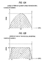
- FIGS. 3A and 3B are views showing kinds of rotary cutter blades shown in FIG. 2 .
- FIGS. 4A to 4 D are views showing the structures of the rotary cutter blades shown in FIG. 2 .
- FIG. 5 is a view showing positional relationships between the rotary cutter blades shown in FIG. 2 and a workpiece.
- FIGS. 6A and 6B are views showing a cum curve graph of a spiral blade of the rotary cutter shown in FIG. 1 . (Hereinafter, the figures are often generally referred to as FIG. 6.)
- FIG. 7A and 7B are views illustrating a function constituting the cam curve shown in FIG. 6 .
- FIG. 8 is a view showing a cam curve equation of the cam curve shown in FIG. 6 .
- FIGS. 9A and 9B are views showing a cum curve graph in the case where the cutter shown in FIG. 1 is a straight blade. (Hereinafter, the figures are often generally referred to as FIG. 9.)
- FIG. 10 is a view showing a cam curve equation of the cam curve shown in FIG. 9 .
- FIGS. 11A and 11B are views showing relationships between the speed pattern shown in FIG. 6 and a torque. (Hereinafter, the figures are often generally referred to as FIG. 11.)
- FIGS. 12A and 12B are views comparing a quadratic functional speed pattern shown in FIG. 6 with a trapezoidal speed pattern in the conventional art. (Hereinafter, the figures are often generally referred to as FIG. 12.)
- FIGS. 13A and 13B are generalized views of the trapezoidal speed pattern shown in FIG. 12 . (Hereinafter, the figures are often generally referred to as FIG. 13.)
- FIG. 14 is a view showing an LV curve of the rotary cutter shown FIG. 1 .
- FIG. 15 is a control block diagram of a lateral sealing mechanism of a vertical continuous packaging machine which is a second embodiment of the invention.
- FIG. 16A and 16B are views schematically showing the structure of the lateral sealing mechanism shown in FIG. 15 . (Hereinafter, the figures are often generally referred to as FIG. 16.)
- FIG. 17 is a view showing positional relationships in the double-heater lateral sealing mechanism shown in FIG. 16 .
- FIGS. 18A and 18B are views showing a cum curve graph of the lateral sealing mechanism shown in FIG. 15 . (Hereinafter, the figures are often generally referred to as FIG. 18.)
- FIG. 19 is a view showing a cam curve equation of the cam curve shown in FIG. 18 .
- FIG. 20 is a control block diagram of a motion controller of the conventional art.
- FIGS. 21A to 21 F are speed pattern diagrams of the controller shown in FIG. 20 .
- FIG. 22 is a block diagram of an electronic cam control in a conventional art.
- FIG. 23 is a control block diagram of a servo motor of the conventional art.
- FIGS. 24A and 24B are views showing a trapezoidal wave speed pattern of the conventional art and a torque. (Hereinafter, the figures are often generally referred to as FIG. 24 .)
- FIGS. 1 to 14 are views showing the first embodiment of the invention.
- 1 denotes a digital controller which performs a constant scan control
- 2 denotes a servo driver which drives a servo motor 3
- 4 denotes a pulse generator for the motor 3
- 11 denotes a rotary cutter which cuts paper, a iron sheet, or the like into a constant length
- 12 denotes a measuring roll which detects the travel distance of a workpiece
- 13 denotes 20 feed rolls for transporting the workpiece
- 14 denotes a registration mark detector which detects a registration mark of the workpiece.
- the reference numeral 20 denotes a counter
- 21 denotes a D/A converter which performs conversion on a command value to the servo driver 2
- 22 denotes a differential circuit
- 23 denotes a multiplier.
- the reference numeral 24 denotes a saw-tooth wave generating circuit which generates a phase in one cycle of a cut length
- 25 denotes the phase
- 26 denotes a speed pattern generator for an electronic cam curve
- 27 denotes a position pattern generator
- 28 denotes a registration mark correcting circuit
- 29 denotes a position command
- 30 denotes a position control gain.
- the first embodiment is used for controlling the rotary cutter which continuously cuts web paper, an iron sheet, or the like that successively travels as shown in FIG. 2, into a preset length and without stopping the travel.
- the rotary cutter 11 is provided with either of straight blades of FIG. 3A, or spiral blades of FIG. 3B depending on the blade attachment shape. Since straight blades require a very high pressure in cutting operation, they are not frequently used. Consequently, spiral blades will be mainly described. With respect to straight blades, therefore, control equations and the like will be described only in a supplemental manner. As shown in FIGS.
- a double, triple, or quadruple blade cutter (the number of blades is indicated by M) may be used.
- M the number of blades
- FIG. 6A shows a speed pattern
- FIG. 6B shows a position pattern
- zone ( 1 ) is a noncutting zone
- zone ( 2 ) is a cutting zone.
- N 1 is a rotational speed in the cutting zone
- n 2 is a speed in the noncutting zone
- Tc is one cycle time
- t 3 is the time of starting the cutting operation
- y 1 is the position pattern of the noncutting zone
- y 2 is the position pattern of the cutting zone
- Y 1 is the start position of the cutting operation.
- V L N 0 ⁇ L 0 /1000 ( m/min )
- N 1 1000 ⁇ V L /2 ⁇ r (rpm).
- V 2 ⁇ N 1 /60 the speed at time t 3
- n 1 60(3 At 2 +2 Bt+C ) (rpm)
- n 2 N 1 (rpm)
- the cam curve equation of the spiral blade is shown in FIG. 8 .
- FIGS. 9 and 10 show the cam curve equation and the cam curve pattern in the case of a straight blade.
- the cam curve for a spiral blade is strictly identical with that for a straight blade except that, in the case of a straight blade, the speed in cutting zone ( 2 ) has a pattern which is proportional to 1/cos ⁇ as shown in FIG. 9 A.
- Pulses output from the measuring roll 12 for detecting the travel distance of a workpiece such as paper or an iron sheet are fetched into the digital controller 1 which performs a constant-period scan control, and then counted by the counter 20 a .
- a phase ⁇ in one cycle where the maximum value is equal to a pulse amount ⁇ M corresponding to the cut length is repeatedly obtained by the saw-tooth wave generating circuit 24 .
- the phase is input into the position pattern generating circuit 27 and the speed pattern generating circuit 26 which correspond to one cycle by a cam curve such as shown also in FIG. 6 described above, and a position command Yref 29 and a speed command are obtained at every moment.
- a feedback control is performed by using a pulse count value from the pulse generator for the servo motor 3 , and a position control is conducted so as to make the position error ⁇ close to 0, thereby realizing the electronic cam control at every moment.
- V(p, u) which is obtained by normalizing the speed that is actually obtained by the differential circuit 22 is multiplied with an output of the speed pattern generating circuit 26 , whereby the speed is used as a feedforward according to the actual travelling speed of the paper or the like, so as to enhance the traceability.
- a registration mark (alignment) which is printed every page simultaneously with printing is detected by the registration mark detector 14 , and a position error or the like is corrected by the registration mark correcting circuit 28 .
- cam curve equations shown in FIGS. 8 and 10 are obtained as those relating to the time t.
- such an equation may be used in a control while replacing the time with the travel distance of the paper or the like, i.e., the phase ⁇ (pulse).
- the time t n can be replaced with the pulse count amount P n (i.e., the phase ⁇ ) from the measuring roll 12 .
- the speed pattern of the noncutting zone shown in FIG. 24A has a trapezoidal waveform, and, in order to satisfy the cycle time and gain the time for stabilizing the speed before the cutting operation, the acceleration or deceleration time is set to be somewhat short as shown in FIG. 24 B. Therefore, the peak of a torque required during acceleration or deceleration is high and the root mean square of the torque Trms tends to be large. In a short cutting operation, particularly, the acceleration or deceleration frequency is high, and hence Trms exceeds 100%. In order to prevent this from occurring, the line speed must be lowered, with the result that the productivity is largely impaired.
- FIG. 11 is a view showing the speed pattern and the torque in the invention.
- the speed pattern of noncutting zone ( 1 ) is a quadratic curve as shown in FIG. 11A Therefore, the torque required for acceleration and deceleration is dispersed over the whole of zone ( 1 ) as shown in FIG. 11B, and hence improvement is enabled.
- FIG. 12 is a view comparing the quadratic functional speed pattern in the invention with the trapezoidal speed pattern in the conventional art.
- a quadratic functional speed pattern such as shown in FIG. 12A
- a trapezoidal speed pattern such as shown in FIG. 12B
- the equation of the quadratic functional speed is indicated by the following equation:
- N ⁇ 4( t ⁇ 0.5) 2 +1. (4)
- the acceleration ax is obtained by differentiating equation (4) as follows:
- the acceleration is as follows:
- Equation (9) contains three as.
- equation (7) of the root mean square in a quadratic function waveform, and equation (10) in the case of a trapezoidal waveform are in the relationship of (7) ⁇ (10), or ⁇ rms of the quadratic function is smaller than that of the trapezoidal waveform.
- FIG. 13 is a view showing a speed pattern which is obtained by generalizing the trapezoidal waveform shown in FIG. 12 while assuming that 0 ⁇ t ⁇ 0.5 is possible.
- the travel distance S 2 in FIG. 13 is:
- the acceleration is as follows:
- Equation (12) contains three ⁇ s.
- the line speed in the case of a short cutting operation must be earlier lowered, but, according to the system of the invention, the cutting operation can is improved so as to be enabled at 100% of the line speed even in a considerably short range. Therefore, the productivity can be improved as compared with the trapezoidal waveform system of the conventional art.
- the acceleration or deceleration time t ⁇ in the case of a speed pattern of a trapezoidal waveform in the conventional art is usually set to be somewhat short. Consequently, this effect is particularly large.
- FIGS. 15 to 19 are views relating to the second embodiment of the invention.
- 41 denotes a digital controller which performs a constant scan control
- 42 denotes a servo driver which drives a servo motor 43
- 44 denotes a pulse generator for the motor 43
- 45 denotes a line PG which detects a line speed for transporting a workpiece such as paper or a film
- 46 a and 46 b denote lateral sealing mechanisms of a packaging machine which has heating faces and which seals sealing faces.
- the reference numerals 50 a and 50 b denote counters, 51 denotes a D/A converter which performs conversion on a command value to the servo driver 2 , 52 denotes a differential circuit, 53 denotes a divider, 54 denotes a multiplier, 55 denotes a saw-tooth wave generating circuit which generates a phase in one cycle of sealing, 56 denotes the phase, 57 denotes a speed pattern generator for an electronic cam curve, 58 denotes a position pattern generator, 59 denotes a position command, and 60 denotes a position control gain.
- the lateral sealing mechanism of a vertical continuous packaging machine such as shown in FIG. 16 which is the second embodiment
- the mechanisms are driven by the servo motor 43 .
- the lateral sealing mechanisms in each of which a heater face in the tip end constitutes a part of a circumference are arranged so as to be bilaterally symmetrical, and lateral heaters press the film under a state where the peripheral speed is equal to the film speed, whereby lateral sealing for a predetermined time (sealing time) is realized.
- FIG. 17 shows positional relationships in the case of the double heating faces 46 in the lateral sealing mechanism.
- FIG. 18A shows a speed pattern
- FIG. 18B shows a position pattern
- zone ( 1 ) is a nonsealing zone
- zone ( 2 ) is a sealing zone.
- N 1 is a rotational speed in the sealing zone
- n 2 is a speed in the nonsealing zone
- Tc is one cycle time
- t 3 is the time of starting the sealing operation
- y 1 is the position pattern of the nonsealing zone
- Y 2 is the position pattern of the sealing zone
- Y 1 is the start position of the sealing operation.
- V L N 0 ⁇ L 0 /1000( m/min )
- N 1 1000 ⁇ V L /2 ⁇ r (rpm).
- rotational position y 2 (1 /M ⁇ Y 1 )/( Tc ⁇ t 3 ) ⁇ ( t ⁇ T c )+1 /M.
- T 1 ⁇ 0 the final time of the sealing zone
- T 2 ⁇ +t 3 the initial time of the sealing zone of the next cycle
- X 1 ⁇ 0 the position at time T 1
- V 2 ⁇ N 1 /60 the speed at time t 3
- n 1 60(3 At 2 +2 Bt+C ) (rpm)
- n 2 N 1 (rpm)
- the cam curve equation of the lateral sealing mechanism 46 is shown in FIG. 19 .
- the above can be automatically realized. Even when conditions are changed or, for example, the length of a bag to be formed is changed, the simultaneous equations in four unknowns are solved by the controller 41 , and a new cam curve (position pattern, speed pattern) is obtained in a moment to realize a control of an excellent traceability.
- Pulses output from the line PG 45 for detecting the travel distance of a film, paper, or the like are fetched into the digital controller 41 which performs a constant-period scan control, and then counted by the counter 50 a .
- a phase ⁇ in one cycle where the maximum value is equal to a pulse amount ⁇ M corresponding to the bag length is repeatedly obtained by the saw-tooth wave generating circuit 55 .
- the phase is input into the position pattern generating circuit 58 and the speed pattern generating circuit 57 which correspond to one cycle described above, and a position command Yref 59 and a speed command are obtained at every moment.
- a feedback control is performed by using a pulse count value from the pulse generator 44 for the servo motor 43 , and a position control is conducted so as to make the position error ⁇ close to ⁇ , thereby realizing the electronic cam control at every moment.
- the cam curve equation of FIG. 19 is previously obtained under the state of 100% of the travelling speed of the film, paper or the like.
- V(p, u) which is obtained by dividing the speed V that is actually obtained by the differential circuit 52 , with 100% of the speed V (100%) is multiplied with an output of the speed pattern generating circuit 57 , whereby the speed is used as a feedforward according to the actual travelling speed of the actual film, paper or the like, so as to enhance the traceability.
- the cam curve equation shown in FIG. 19 is obtained as that relating to the time t.
- such an equation may be used in a control while replacing the time with the travel distance of the film, paper or the like, i.e., the phase ⁇ (pulse).
- the time t n can be replaced with the pulse count amount P n (i.e., the phase ⁇ ) from the measuring roll 12 .
- the embodiment has a very high traceability and can cope with a change in conditions in a completely automatic manner.
- a lateral sealing mechanism is coupled to a driving shaft for transporting a workpiece such as a film, and driven at constant rotation.
- a single-heater type therefore, only a bag of a length which corresponds to a circumference can be sealed, and, in a double-heater lateral sealing mechanism of the 180° symmetric type, only a bag of a length which corresponds to a half circumference can be sealed.
- the lateral sealing mechanism must be replaced with one having a different radius.
- the embodiment is enabled by the electronic cam to rapidly automatically cope with all bag lengths. Therefore, the cost can be remarkably reduced, and the productivity can be improved.
- a position loop is formed in a whole region on the basis of an electronic cam curve, an electronic cam curve of a cubic function is used as a position pattern for a noncutting zone, and an electronic cam curve of a quadratic function is used as a speed pattern, whereby a control is enabled with causing a same algorithm to automatically cope with long and short cutting operations and a change of a line speed.
- the electronic cam control using an electronic cam curve in which the position pattern in a noncutting zone is a cubic function and the speed pattern is a quadratic function produces effects that a control due to the same algorithm can automatically cope with both long and short cut lengths or bag lengths and a change in conditions, that its traceability is largely enhanced, and that the control efficiency of the rotary cutter is improved.
- a position loop is formed in a whole region on the basis of an electronic cam curve, an electronic cam curve of a cubic function is used as a position pattern for a noncutting zone, and an electronic cam curve of a quadratic function is used as a speed pattern, whereby necessity of reduction of the line speed is eliminated even in a length range which is shorter than a range of a conventional art, and a cutting operation is enabled while maintaining the line speed to 100%.
- the cutting is enabled without reducing the speed, thereby producing an effect that the productivity can be largely improved.
- a cubic function is used in a position command according to a continuous correlation control system including a prediction to a start of a work in a next cycle, and a quadratic function is used in a speed feedforward, whereby an optimum electronic cam curve is obtained while allowing a bag length or a cut length of the workpiece to automatically perform correspondence irrespective of a value of peripheral length/M.
Landscapes
- Engineering & Computer Science (AREA)
- Life Sciences & Earth Sciences (AREA)
- Mechanical Engineering (AREA)
- Forests & Forestry (AREA)
- Physics & Mathematics (AREA)
- Automation & Control Theory (AREA)
- General Physics & Mathematics (AREA)
- Manufacturing & Machinery (AREA)
- Human Computer Interaction (AREA)
- Control Of Velocity Or Acceleration (AREA)
- Control Of Cutting Processes (AREA)
- Control Of Position Or Direction (AREA)
- Auxiliary Devices For And Details Of Packaging Control (AREA)
Applications Claiming Priority (3)
| Application Number | Priority Date | Filing Date | Title |
|---|---|---|---|
| JP00452399A JP3387842B2 (ja) | 1999-01-11 | 1999-01-11 | 電子カム方式ロータリカッタ制御方法および電子カム曲線生成方法 |
| JPP.11-004523 | 1999-01-11 | ||
| PCT/JP2000/000046 WO2000041858A1 (fr) | 1999-01-11 | 2000-01-07 | Procede de commande d'outil rotatif de coupe a came electronique et procede de generation de courbe de came electronique |
Publications (1)
| Publication Number | Publication Date |
|---|---|
| US6781339B1 true US6781339B1 (en) | 2004-08-24 |
Family
ID=11586415
Family Applications (1)
| Application Number | Title | Priority Date | Filing Date |
|---|---|---|---|
| US09/889,047 Expired - Lifetime US6781339B1 (en) | 1999-01-11 | 2000-01-07 | Method of controlling an electronic cam type rotary cutter, and method of producing an electronic cam curve |
Country Status (8)
| Country | Link |
|---|---|
| US (1) | US6781339B1 (de) |
| EP (1) | EP1151830B1 (de) |
| JP (1) | JP3387842B2 (de) |
| KR (1) | KR100635660B1 (de) |
| CN (1) | CN1160175C (de) |
| DE (1) | DE60009462T2 (de) |
| TW (1) | TW477921B (de) |
| WO (1) | WO2000041858A1 (de) |
Cited By (14)
| Publication number | Priority date | Publication date | Assignee | Title |
|---|---|---|---|---|
| US20040049302A1 (en) * | 2000-10-19 | 2004-03-11 | Ikuo Nagamatsu | Electronic cam device and method of preparing cam data in electronic cam device |
| US6842651B1 (en) * | 1999-05-06 | 2005-01-11 | Kabushiki Kaisha Yaskawa Denki | Programmable controller having plural speed pattern generators |
| US20050126355A1 (en) * | 2003-12-10 | 2005-06-16 | Reiner Schonberger | Device and method for cutting a material web |
| US20050237012A1 (en) * | 2004-04-21 | 2005-10-27 | Komori Corporation | Synchronous control method and device of the same |
| US20060055359A1 (en) * | 2002-12-27 | 2006-03-16 | Makoto Akama | Reverse rotation preventing electronic cam curve generating method based on electronic cam type rotary cutter control and control device therefor |
| US20060113029A1 (en) * | 2004-11-01 | 2006-06-01 | Lemens Paul J | Processing apparatus |
| US20060144187A1 (en) * | 2004-11-17 | 2006-07-06 | Hiroyuki Maeda | Method of controlling electronic cam and servo motor control system |
| US20060197484A1 (en) * | 2005-02-21 | 2006-09-07 | Hironori Ohashi | Motor controller |
| US7891276B2 (en) | 2007-08-31 | 2011-02-22 | Kimbelry-Clark Worldwide, Inc. | System and method for controlling the length of a discrete segment of a continuous web of elastic material |
| WO2012008899A1 (en) * | 2010-07-14 | 2012-01-19 | Business Forms Equipment Ab | Device and method for cutting, perforating or folding a thin bendable material |
| CN103714042A (zh) * | 2013-12-06 | 2014-04-09 | 苏州逸美德自动化科技有限公司 | 一种变形五次多项式凸轮运行曲线算法 |
| US20180015622A1 (en) * | 2015-03-27 | 2018-01-18 | Hp Indigo B.V. | Rotary cutting device |
| US20180361605A1 (en) * | 2016-01-18 | 2018-12-20 | Tetra Laval Holdings & Finance S.A. | A filling machine and a method for filling a package of a web of packaging material with a food product |
| CN110825025A (zh) * | 2019-10-24 | 2020-02-21 | 威科达(东莞)智能控制有限公司 | 一种用于瓦楞纸前缘送纸的免编程电子凸轮曲线生成方法 |
Families Citing this family (23)
| Publication number | Priority date | Publication date | Assignee | Title |
|---|---|---|---|---|
| DE10053247A1 (de) * | 2000-10-26 | 2002-05-29 | Rexroth Indramat Gmbh | Verfahren und Vorrichtung zum Umschalten des Eingriffsabstandes eines Werkzeuges in eine vorbeilaufende Materialbahn |
| CN100447688C (zh) * | 2004-11-17 | 2008-12-31 | 欧姆龙株式会社 | 电子凸轮的控制方法及伺服电机控制系统 |
| JP2008531392A (ja) * | 2005-03-03 | 2008-08-14 | ジーディーエックス・ノース・アメリカ・インコーポレーテッド | 補強されたシール用、トリミング用又は案内用のストリップ |
| JP2008000873A (ja) * | 2006-06-26 | 2008-01-10 | Yonemori Tekkosho:Kk | 剪断装置 |
| DE102007005009A1 (de) * | 2007-02-01 | 2008-08-07 | Man Roland Druckmaschinen Ag | Querperforationseinheit eines Falzapparats einer Druckmaschine sowie Verfahren zum Betreiben einer Querperforationseinheit eines Falzapparats |
| DE102007009809A1 (de) * | 2007-02-28 | 2008-09-04 | Man Roland Druckmaschinen Ag | Querperforationseinheit eines Falzapparats einer Druckmaschine sowie Verfahren zum Betreiben einer Querperforationseinheit eines Falzapparats |
| DE102007034834A1 (de) * | 2007-07-26 | 2009-01-29 | Robert Bosch Gmbh | Verfahren und Vorrichtung zum Optimieren von Querbearbeitungsvorgängen |
| CN102109855B (zh) * | 2010-12-21 | 2013-11-20 | 天津市亚安科技股份有限公司 | 一种用于调节云台电机速度曲线的方法及系统 |
| JP4973792B1 (ja) * | 2011-03-15 | 2012-07-11 | オムロン株式会社 | 演算ユニット、出力制御方法、およびプログラム |
| CN103076756A (zh) * | 2011-10-25 | 2013-05-01 | 科比传动技术(上海)有限公司 | 伺服驱动器中实现带电子凸轮功能的方法 |
| CN103163822B (zh) * | 2011-12-19 | 2015-09-16 | 苏州汇川技术有限公司 | 电子凸轮控制装置及方法 |
| CN103744346B (zh) * | 2013-12-30 | 2016-09-14 | 南京埃斯顿自动化股份有限公司 | 一种电子凸轮曲线生成方法 |
| WO2016059298A1 (en) * | 2014-10-15 | 2016-04-21 | Raute Oyj | Control of clipping |
| TWI557521B (zh) * | 2015-11-03 | 2016-11-11 | 新代科技股份有限公司 | 電子凸輪控制裝置及電子凸輪曲線生成方法 |
| CN106094718B (zh) * | 2016-02-23 | 2018-11-02 | 泉州市汉威机械制造有限公司 | 一种电子凸轮补偿控制方法 |
| CN106406219B (zh) * | 2016-12-16 | 2018-10-02 | 威科达(东莞)智能控制有限公司 | 一种用于横切的免编程电子凸轮曲线生成方法 |
| CN107284751B (zh) * | 2017-05-12 | 2020-05-26 | 深圳市汇川控制技术有限公司 | 一种包装膜剪切控制系统及方法 |
| CN107315389B (zh) * | 2017-05-23 | 2021-06-08 | 泉州市汉威机械制造有限公司 | 一种多次方变形凸轮曲线的设计方法 |
| CN108415375B (zh) * | 2018-02-07 | 2019-12-27 | 大连理工大学 | 一种用于多主轴加工的电子凸轮控制方法 |
| AT521468B1 (de) * | 2019-01-31 | 2020-02-15 | Andritz Ag Maschf | Verfahren zum querschneiden einer entlang einer bewegungsrichtung bewegten materialbahn sowie vorrichtung hierzu |
| CN111923144A (zh) * | 2020-08-05 | 2020-11-13 | 苏州安洁科技股份有限公司 | 一种自动扫描对位冲切工艺 |
| JP7438097B2 (ja) | 2020-12-25 | 2024-02-26 | 三菱電機株式会社 | 駆動指令生成装置、同期制御システム及び学習装置 |
| CN114326579A (zh) * | 2021-12-21 | 2022-04-12 | 杭州之山智控技术有限公司 | 模切专用伺服驱动器电子凸轮功能实现方法及伺服驱动器 |
Citations (18)
| Publication number | Priority date | Publication date | Assignee | Title |
|---|---|---|---|---|
| JPS49890A (de) | 1972-04-15 | 1974-01-07 | ||
| US4165665A (en) * | 1976-12-23 | 1979-08-28 | Fuji Photo Film Co., Ltd. | Web cutting apparatus |
| US4170155A (en) | 1977-11-03 | 1979-10-09 | Nihon Electronic Industry Co., Ltd. | Rotary cutter for successively cutting moving material to lengths |
| JPS55101397A (en) | 1979-01-25 | 1980-08-02 | Yaskawa Denki Seisakusho Kk | Standard size cutting control method of sheet |
| EP0035462A2 (de) | 1980-01-31 | 1981-09-09 | Beloit Corporation | Zyklischer elektrischer Antrieb für einen feinen und beschichteten Papierschneider |
| US4464959A (en) | 1981-05-11 | 1984-08-14 | Bethlehem Steel Corp. | Adaptive control for a dividing shear |
| US4720990A (en) * | 1984-10-11 | 1988-01-26 | Th. Kieserling | Ejector mechanism for eccentric presses |
| US4724732A (en) | 1984-11-30 | 1988-02-16 | Mitsubishi Jukogyo Kabushiki Kaisha | Method of controlling a rotary cutter |
| JPH05337729A (ja) | 1992-06-08 | 1993-12-21 | Mitsubishi Electric Corp | モーションコントローラ |
| JPH06262588A (ja) | 1993-03-17 | 1994-09-20 | Nippon Reliance Kk | ロータリーカッタ制御方式 |
| JPH07311609A (ja) | 1994-05-19 | 1995-11-28 | Toppan Printing Co Ltd | 電子カム |
| US5554087A (en) * | 1994-11-15 | 1996-09-10 | Industrial Technology Research Institute | Tool pivoting mechanism of a tool magazine |
| JPH09277114A (ja) | 1996-04-17 | 1997-10-28 | Showa Denki Seisakusho:Kk | 走間加工機の制御装置 |
| US5697881A (en) * | 1993-12-01 | 1997-12-16 | Toshiba Kikai Kabushiki Kaisha | Folding machine with collection mechanism |
| US5765460A (en) | 1995-12-18 | 1998-06-16 | Wathieu; Patrick | Paper cutter for variable format |
| US5826479A (en) * | 1993-08-03 | 1998-10-27 | Nippondenso Co., Ltd. | Cutting device |
| US5850772A (en) | 1996-06-24 | 1998-12-22 | Nusco Co. Ltd. | Method of controlling fly cutting rotary shear |
| US5950531A (en) * | 1997-05-28 | 1999-09-14 | Apic Yamada Corporation | Electric press machine |
-
1999
- 1999-01-11 JP JP00452399A patent/JP3387842B2/ja not_active Expired - Fee Related
- 1999-12-23 TW TW088122810A patent/TW477921B/zh not_active IP Right Cessation
-
2000
- 2000-01-07 CN CNB008026912A patent/CN1160175C/zh not_active Expired - Fee Related
- 2000-01-07 DE DE60009462T patent/DE60009462T2/de not_active Expired - Lifetime
- 2000-01-07 WO PCT/JP2000/000046 patent/WO2000041858A1/ja active IP Right Grant
- 2000-01-07 US US09/889,047 patent/US6781339B1/en not_active Expired - Lifetime
- 2000-01-07 KR KR1020017008544A patent/KR100635660B1/ko not_active IP Right Cessation
- 2000-01-07 EP EP00900147A patent/EP1151830B1/de not_active Expired - Lifetime
Patent Citations (18)
| Publication number | Priority date | Publication date | Assignee | Title |
|---|---|---|---|---|
| JPS49890A (de) | 1972-04-15 | 1974-01-07 | ||
| US4165665A (en) * | 1976-12-23 | 1979-08-28 | Fuji Photo Film Co., Ltd. | Web cutting apparatus |
| US4170155A (en) | 1977-11-03 | 1979-10-09 | Nihon Electronic Industry Co., Ltd. | Rotary cutter for successively cutting moving material to lengths |
| JPS55101397A (en) | 1979-01-25 | 1980-08-02 | Yaskawa Denki Seisakusho Kk | Standard size cutting control method of sheet |
| EP0035462A2 (de) | 1980-01-31 | 1981-09-09 | Beloit Corporation | Zyklischer elektrischer Antrieb für einen feinen und beschichteten Papierschneider |
| US4464959A (en) | 1981-05-11 | 1984-08-14 | Bethlehem Steel Corp. | Adaptive control for a dividing shear |
| US4720990A (en) * | 1984-10-11 | 1988-01-26 | Th. Kieserling | Ejector mechanism for eccentric presses |
| US4724732A (en) | 1984-11-30 | 1988-02-16 | Mitsubishi Jukogyo Kabushiki Kaisha | Method of controlling a rotary cutter |
| JPH05337729A (ja) | 1992-06-08 | 1993-12-21 | Mitsubishi Electric Corp | モーションコントローラ |
| JPH06262588A (ja) | 1993-03-17 | 1994-09-20 | Nippon Reliance Kk | ロータリーカッタ制御方式 |
| US5826479A (en) * | 1993-08-03 | 1998-10-27 | Nippondenso Co., Ltd. | Cutting device |
| US5697881A (en) * | 1993-12-01 | 1997-12-16 | Toshiba Kikai Kabushiki Kaisha | Folding machine with collection mechanism |
| JPH07311609A (ja) | 1994-05-19 | 1995-11-28 | Toppan Printing Co Ltd | 電子カム |
| US5554087A (en) * | 1994-11-15 | 1996-09-10 | Industrial Technology Research Institute | Tool pivoting mechanism of a tool magazine |
| US5765460A (en) | 1995-12-18 | 1998-06-16 | Wathieu; Patrick | Paper cutter for variable format |
| JPH09277114A (ja) | 1996-04-17 | 1997-10-28 | Showa Denki Seisakusho:Kk | 走間加工機の制御装置 |
| US5850772A (en) | 1996-06-24 | 1998-12-22 | Nusco Co. Ltd. | Method of controlling fly cutting rotary shear |
| US5950531A (en) * | 1997-05-28 | 1999-09-14 | Apic Yamada Corporation | Electric press machine |
Non-Patent Citations (3)
| Title |
|---|
| International Search Report. |
| Patent Abstracts of Japan 05-337729, Dec. 21, 1993. |
| Patent Abstracts of Japan 07-311609, Nov. 28, 1995. |
Cited By (26)
| Publication number | Priority date | Publication date | Assignee | Title |
|---|---|---|---|---|
| US6842651B1 (en) * | 1999-05-06 | 2005-01-11 | Kabushiki Kaisha Yaskawa Denki | Programmable controller having plural speed pattern generators |
| US20040049302A1 (en) * | 2000-10-19 | 2004-03-11 | Ikuo Nagamatsu | Electronic cam device and method of preparing cam data in electronic cam device |
| US7228294B2 (en) * | 2000-10-19 | 2007-06-05 | Kabushiki Kaisha Yaskawa Denki | Electronic cam device and method of preparing cam data in electronic cam device |
| US20060055359A1 (en) * | 2002-12-27 | 2006-03-16 | Makoto Akama | Reverse rotation preventing electronic cam curve generating method based on electronic cam type rotary cutter control and control device therefor |
| US7191031B2 (en) * | 2002-12-27 | 2007-03-13 | Kabushiki Kaisha Yaskawa Denki | Reverse rotation preventing electronic cam curve generating method based on electronic cam type rotary cutter control and control device therefor |
| US20050126355A1 (en) * | 2003-12-10 | 2005-06-16 | Reiner Schonberger | Device and method for cutting a material web |
| US20050237012A1 (en) * | 2004-04-21 | 2005-10-27 | Komori Corporation | Synchronous control method and device of the same |
| US7202616B2 (en) * | 2004-04-21 | 2007-04-10 | Komori Corporation | Synchronous control method and device of the same |
| US7338572B2 (en) | 2004-11-01 | 2008-03-04 | Esselte Corporation | Processing apparatus |
| US20060113029A1 (en) * | 2004-11-01 | 2006-06-01 | Lemens Paul J | Processing apparatus |
| US7771553B2 (en) | 2004-11-01 | 2010-08-10 | Esselte Corporation | Processing apparatus |
| US20080099123A1 (en) * | 2004-11-01 | 2008-05-01 | Esselte Business Corporation | Processing apparatus |
| US20060144187A1 (en) * | 2004-11-17 | 2006-07-06 | Hiroyuki Maeda | Method of controlling electronic cam and servo motor control system |
| US7603188B2 (en) * | 2004-11-17 | 2009-10-13 | Omron Corporation | Servo motor control system |
| US7151352B2 (en) * | 2005-02-21 | 2006-12-19 | Hitachi Industrial Equipment Systems Co., Ltd. | Motor controller |
| US20060197484A1 (en) * | 2005-02-21 | 2006-09-07 | Hironori Ohashi | Motor controller |
| US7891276B2 (en) | 2007-08-31 | 2011-02-22 | Kimbelry-Clark Worldwide, Inc. | System and method for controlling the length of a discrete segment of a continuous web of elastic material |
| US8196497B2 (en) | 2007-08-31 | 2012-06-12 | Kimberly-Clark Worldwide, Inc. | System and method for controlling the length of a discrete segment of a continuous web of elastic material |
| WO2012008899A1 (en) * | 2010-07-14 | 2012-01-19 | Business Forms Equipment Ab | Device and method for cutting, perforating or folding a thin bendable material |
| CN103714042A (zh) * | 2013-12-06 | 2014-04-09 | 苏州逸美德自动化科技有限公司 | 一种变形五次多项式凸轮运行曲线算法 |
| CN103714042B (zh) * | 2013-12-06 | 2017-05-03 | 苏州逸美德科技有限公司 | 一种变形五次多项式凸轮运行曲线设计方法 |
| US20180015622A1 (en) * | 2015-03-27 | 2018-01-18 | Hp Indigo B.V. | Rotary cutting device |
| US20180361605A1 (en) * | 2016-01-18 | 2018-12-20 | Tetra Laval Holdings & Finance S.A. | A filling machine and a method for filling a package of a web of packaging material with a food product |
| US10974407B2 (en) * | 2016-01-18 | 2021-04-13 | Tetra Laval Holdings & Finance S.A. | Filling machine and a method for filling a package of a web of packaging material with a food product |
| CN110825025A (zh) * | 2019-10-24 | 2020-02-21 | 威科达(东莞)智能控制有限公司 | 一种用于瓦楞纸前缘送纸的免编程电子凸轮曲线生成方法 |
| CN110825025B (zh) * | 2019-10-24 | 2022-06-17 | 威科达(东莞)智能控制有限公司 | 一种用于瓦楞纸前缘送纸的免编程电子凸轮曲线生成方法 |
Also Published As
| Publication number | Publication date |
|---|---|
| CN1160175C (zh) | 2004-08-04 |
| TW477921B (en) | 2002-03-01 |
| JP3387842B2 (ja) | 2003-03-17 |
| KR20010101389A (ko) | 2001-11-14 |
| DE60009462D1 (de) | 2004-05-06 |
| EP1151830A4 (de) | 2002-04-03 |
| JP2000198094A (ja) | 2000-07-18 |
| EP1151830B1 (de) | 2004-03-31 |
| KR100635660B1 (ko) | 2006-10-17 |
| EP1151830A1 (de) | 2001-11-07 |
| DE60009462T2 (de) | 2004-08-19 |
| WO2000041858A1 (fr) | 2000-07-20 |
| CN1336863A (zh) | 2002-02-20 |
Similar Documents
| Publication | Publication Date | Title |
|---|---|---|
| US6781339B1 (en) | Method of controlling an electronic cam type rotary cutter, and method of producing an electronic cam curve | |
| US5138815A (en) | Microprocessor controlled SCR motor drives for wrapping machine | |
| US5455764A (en) | Register control system, particularly for off-line web finishing | |
| JPS62136397A (ja) | 切断装置 | |
| US6059705A (en) | Method and apparatus for registering processing heads | |
| CN100519024C (zh) | 防止反转的电子凸轮曲线生成方法及其控制装置 | |
| EP0204845B1 (de) | Steuerungsverfahren einer rotierenden schneidevorrichtung | |
| JP2779901B2 (ja) | 製袋用フィルムの送り制御装置 | |
| US6139479A (en) | Apparatus and method for manufacture of containers of variable length | |
| CN114261589A (zh) | 一种枕式包装机的自动色标校准方法、系统及介质 | |
| CA2426971C (en) | Method and device for adjusting the degree of engagement of a tool with a web of material running past it | |
| US4114079A (en) | Rotary cutter drive control with electric motor | |
| JP3504201B2 (ja) | ロータリーカッタの制御装置 | |
| JPH01111635A (ja) | 切断長さ自動測定・制御包装機械 | |
| JP3391051B2 (ja) | 切断機 | |
| JPH05337729A (ja) | モーションコントローラ | |
| JPH06144424A (ja) | 切断機 | |
| JP2548896Y2 (ja) | 同期位置決め装置 | |
| JPH02116412A (ja) | 走行中作業用作業体駆動装置 | |
| JP2005298010A (ja) | Ptpシートのマーク合わせ装置 | |
| JPH01111620A (ja) | 包装機械の包装紙送り制御装置 | |
| JP2001129790A (ja) | ロータリーカッタの制御装置 | |
| JPH01111636A (ja) | 包装機械のレジストレーション制御装置 | |
| JPS59224210A (ja) | 走間切断機制御装置 | |
| JPH02243293A (ja) | プレプリント切断制御装置 |
Legal Events
| Date | Code | Title | Description |
|---|---|---|---|
| AS | Assignment |
Owner name: KABUSHIKI KAISHA YASKAWA DENKI, JAPAN Free format text: ASSIGNMENT OF ASSIGNORS INTEREST;ASSIGNOR:IKEGUCHI, MASAO;REEL/FRAME:012055/0233 Effective date: 20010625 |
|
| FEPP | Fee payment procedure |
Free format text: PAYOR NUMBER ASSIGNED (ORIGINAL EVENT CODE: ASPN); ENTITY STATUS OF PATENT OWNER: LARGE ENTITY |
|
| STCF | Information on status: patent grant |
Free format text: PATENTED CASE |
|
| FPAY | Fee payment |
Year of fee payment: 4 |
|
| FPAY | Fee payment |
Year of fee payment: 8 |
|
| FPAY | Fee payment |
Year of fee payment: 12 |