US6682239B2 - Thermal printer unit and thermal printer - Google Patents
Thermal printer unit and thermal printer Download PDFInfo
- Publication number
- US6682239B2 US6682239B2 US09/881,739 US88173901A US6682239B2 US 6682239 B2 US6682239 B2 US 6682239B2 US 88173901 A US88173901 A US 88173901A US 6682239 B2 US6682239 B2 US 6682239B2
- Authority
- US
- United States
- Prior art keywords
- platen roller
- thermal head
- condition
- thermal
- paper
- Prior art date
- Legal status (The legal status is an assumption and is not a legal conclusion. Google has not performed a legal analysis and makes no representation as to the accuracy of the status listed.)
- Expired - Lifetime, expires
Links
Images




Classifications
-
- B—PERFORMING OPERATIONS; TRANSPORTING
- B41—PRINTING; LINING MACHINES; TYPEWRITERS; STAMPS
- B41J—TYPEWRITERS; SELECTIVE PRINTING MECHANISMS, i.e. MECHANISMS PRINTING OTHERWISE THAN FROM A FORME; CORRECTION OF TYPOGRAPHICAL ERRORS
- B41J11/00—Devices or arrangements of selective printing mechanisms, e.g. ink-jet printers or thermal printers, for supporting or handling copy material in sheet or web form
- B41J11/02—Platens
- B41J11/04—Roller platens
-
- B—PERFORMING OPERATIONS; TRANSPORTING
- B41—PRINTING; LINING MACHINES; TYPEWRITERS; STAMPS
- B41J—TYPEWRITERS; SELECTIVE PRINTING MECHANISMS, i.e. MECHANISMS PRINTING OTHERWISE THAN FROM A FORME; CORRECTION OF TYPOGRAPHICAL ERRORS
- B41J15/00—Devices or arrangements of selective printing mechanisms, e.g. ink-jet printers or thermal printers, specially adapted for supporting or handling copy material in continuous form, e.g. webs
- B41J15/04—Supporting, feeding, or guiding devices; Mountings for web rolls or spindles
- B41J15/042—Supporting, feeding, or guiding devices; Mountings for web rolls or spindles for loading rolled-up continuous copy material into printers, e.g. for replacing a used-up paper roll; Point-of-sale printers with openable casings allowing access to the rolled-up continuous copy material
Definitions
- the present invention relates to a thermal printer unit and a thermal printer, and, in particular, to a thermal printer unit and a thermal printer applied to a portable terminal apparatus and a POS (Point Of Service) apparatus, and employing rolled paper.
- POS Point Of Service
- a printer of a portable terminal apparatus or a POS apparatus For a printer of a portable terminal apparatus or a POS apparatus, increase in printing speed and easy exchange of printing paper are demanded. In order to deal with these requests, a line thermal printer employing rolled paper as printing paper is used.
- FIG. 1 shows a line thermal printer 10 in the related art.
- FIG. 2 shows a general configuration of the line thermal printer 10 shown in FIG. 1 .
- FIGS. 3A, 3 B and 3 C illustrate operation of a platen roller and a thermal head of the line thermal printer 10 shown in FIG. 1 .
- the line thermal printer 10 is of a clam-shell-type, and has a body 11 and a cover 13 supported by a shaft 12 on the body 11 .
- the body 11 has a paper roll containing part 11 a in which a paper roll is contained, and, also, has the thermal head 15 incorporated therein together with a head pressing spring 14 .
- the platen roller 16 is supported on an extending end of the cover 13 .
- grooves 18 in which a shaft 17 of the platen roller 16 is fitted are formed in the body 11 . Each of these grooves 18 has a shape of a vertically extended straight line and has an opening 18 a at the top thereof, as shown in FIG. 3 A.
- the line thermal printer 10 enters a condition, shown in FIGS. 2 and 3C, such that the printer 10 can perform printing as a result of: the cover 13 being opened; the paper roll 20 having a paper end 21 thereof unwound partially being contained in the paper roll containing part 11 a ; the unwound paper end 21 being drawn out so as to pass in front of the thermal head 15 ; and the cover 13 being closed. That is, at the last stage of closing the cover 13 , the platen roller 16 comes into contact with the thermal head 15 and pushes it out, the shaft 17 enters the grooves 18 , and, the platen roller 16 reaches a position shown in FIGS. 2 and 3C, as shown in FIGS. 3A and 3B.
- the head pressing spring 14 presses the thermal head 15 onto the platen roller 16 by a force F 1 (functioning as a head pressure), and the paper end 21 is sandwiched between the thermal head 15 and platen roller 16 , as shown in FIG. 2 . Further, the platen roller 16 and cover 13 are locked together in a condition in which the shaft 17 of the platen roller 16 is fitted into the grooves 18 and are pressed onto the bottoms of the grooves 18 by the above-mentioned force F 1 .
- the paper roll 20 is exchanged after the cover 13 is opened as a result of the end of the cover on the side of the platen roller 16 being pulled up with a strong force.
- the printer 10 when the cover 13 is opened, a wide space is formed between the thermal head 15 and platen roller 16 , and, thereby, exchange of the paper roll 20 can be easily performed. Further, the cover 13 is locked through the operation of closing the cover 13 , and the lock is released as a result of the cover 13 being pulled up. Accordingly, any other special locking operation or lock releasing operation is needed to be performed. Accordingly, the printer 10 is convenient in operation thereof.
- the line thermal printer which is incorporated in the portable terminal apparatus is required to have a strong locking mechanism such that the cover 13 is prevented from being opened by accident, even when the portable terminal apparatus is knocked or dropped.
- the head pressure may become larger than a proper head pressure. Thereby, the printing quality may be degraded, the thermal head 15 may be easily worn so as to have a shorter life, and so forth.
- the thermal head 15 is inclined in the direction of the grooves 18 as shown in FIG. 2 so that the force F 1 is directed obliquely downward. Thereby, at the last stage of closing the cover 13 , the platen roller 16 may come into contact with a top corner 15 a of the thermal head 15 strongly, as shown in FIG. 3 A. Thereby, the platen roller 16 may be harmed.
- FIG. 11 shows a line thermal printer unit 130 incorporated in another clam-shell-type line thermal printer in the related art.
- a thermal head assembly 132 is incorporated into a frame 131
- a platen roller assembly 133 is incorporated into the frame 131 detachably.
- a photosensor 134 for detecting roll paper is mounted, and, also, a mechanical switch 135 for detecting that the platen roller assembly is mounted at a proper position is mounted on a side wall of the frame 131 .
- a detecting knob part 135 a of the mechanical switch 135 projects into a depressed receiving part 138 of the frame 131 used for mounting the platen roller assembly 133 therein.
- a flexible cable 136 extends from the photosensor 134 , while a normal covered cable 137 extends from the mechanical switch 137 .
- the mechanical switch 135 is mounted on the outer wall of the frame 131 . Accordingly, the substantial lateral length of the line thermal printer unit 130 becomes larger by the mechanical switch 135 than that of the frame 131 itself.
- the photosensor 134 and mechanical switch 135 are components different in type therebetween, the manufacturing costs thereof are high.
- An object of the present invention is to provide a thermal printer unit and a thermal printer in which the above-described problems are solved.
- a thermal printer unit according to the present invention comprises:
- the thermal head assembly comprises:
- thermo head mounted on the frame
- a spring member mounted on the frame and applying a head pressure to the thermal head
- each platen roller receiving part comprises:
- a projection part formed relatively by the vertical groove part and horizontal groove part, located above the horizontal groove part, and projecting from a depth part of the horizontal groove part toward the thermal head, and
- both ends of the platen roller are inserted into the horizontal groove parts of said platen roller receiving parts, respectively, and, also, are pressed by the spring member via the thermal head into the depth parts thereof, respectively.
- both ends of the platen roller are loaded into the depth parts of the horizontal groove parts of the platen roller receiving parts in a condition in which the ends of the platen roller being pressed toward the depth parts of the horizontal groove parts by the spring member.
- the platen roller is locked into the platen roller receiving parts.
- by adjusting the dimension and shape of the projection parts it is possible to control the strength of locking of the platen roller into the platen roller receiving parts without changing the head pressure applied to the thermal head by the spring member. Accordingly, it is possible to achieve an appropriate strength of the locking of the platen roller while maintaining the printing quality.
- the platen roller may comprise bearing members at both ends thereof;
- the bearing members rotatably support the both ends of the platen roller in the horizontal groove parts, respectively.
- a member may be provided for covering the top end of the thermal head so as to prevent the platen roller from directly coming into contact with the top end of the thermal head.
- the platen roller when the platen roller is being fitted into the platen roller receiving parts, the platen roller can be prevented from coming into contact with the top end of the thermal head directly. Accordingly, it is possible to prevent the platen roller from being harmed.
- a thermal printer according to the present invention comprises:
- a body comprising a paper roll containing part for holding a paper roll;
- a thermal head assembly mounted on the body, and comprising: a frame having platen roller receiving parts receiving both ends of a platen roller, respectively; a thermal head mounted on the frame; and a spring member mounted on the frame and applying a head pressure to the thermal head; and
- a cover rotatably supported on the body, supporting the platen roller, and covering an opening of the paper roll containing part
- the platen roller in a condition in which the opening of the paper roll containing part is covered by the cover, the platen roller is pressed onto the thermal head, and the platen roller is fitted into the platen roller receiving parts so that the cover is maintained in the condition in which the opening is covered by the cover, and
- each platen roller receiving part comprises:
- a projection part formed relatively by the vertical groove part and horizontal groove part, located above the horizontal groove part, and projecting from a depth part of the horizontal groove part toward the thermal head, and
- both ends of the platen roller are inserted into the horizontal groove parts of the platen roller receiving parts, respectively, and, also, are pressed by the spring member through the thermal head into the depth parts thereof, respectively.
- both ends of the platen roller are loaded into the recess parts of the horizontal groove parts of the platen roller receiving parts in a condition in which the ends of the platen roller being pressed toward the depth parts of the horizontal groove parts by the spring member.
- the platen roller is locked into the platen roller receiving parts.
- by adjusting the dimension and shape of the projection parts it is possible to control the strength of locking of the platen roller into the platen roller receiving parts without changing the head pressure applied to the thermal head by the spring member. Accordingly, it is possible to achieve an appropriate strength of the locking of the platen roller while maintaining the printing quality.
- the platen roller may comprise bearing members at both ends thereof;
- the bearing members rotatably support the both ends of the platen roller in the horizontal groove parts, respectively.
- a member may be provided for covering the top end of the thermal head so as to prevent the platen roller from directly coming into contact with the top end of the thermal head.
- the platen roller when the platen roller is being fitted into the platen roller receiving parts, the platen roller can be prevented from coming into contact with the top end of the thermal head directly. Accordingly, it is possible to prevent the platen roller from being harmed.
- a position on an outline of the platen roller at which the thermal head comes into contact with the platen roller loaded into the horizontal groove parts may be different in a direction reverse to a direction in which the platen roller rotates during feeding the paper from a position on the side of the thermal head at which the outline of the platen roller is intersected by a straight line passing through both the rotational axis of the cover and the center of the platen roller loaded into the horizontal groove part.
- the angle of inclination of the thermal head with respect to a bottom surface of the frame becomes nearly 90 degrees, and a dimension the top end of the thermal head projects toward the platen roller is short, so that a hit of the platen roller by the top end of the thermal head becomes a weaker one, and, thus, the platen roller is prevented from being harmed thereby.
- a thermal printer unit according to another aspect of the present invention comprises:
- the thermal head assembly comprises:
- a frame having a platen roller receiving part receiving the platen roller
- thermo head mounted on the frame
- a spring member mounted on the frame and applying a head pressure to the thermal head
- the thermal head assembly further comprises photosensors provided on the rear side of the platen roller receiving part so as to face the platen roller;
- the photosensors are used for detecting, through a combination of outputs thereof, any of a condition in which printing operation of the printer unit can be properly performed, a condition in which paper for the printing is nearly run out, a condition in which the paper for the printing is run out, and a condition in which the platen roller is removed from the platen roller receiving part.
- the lateral dimension of the thermal printer unit is prevented from increasing much although the photosensors are provided for detecting various conditions of the printer unit. Further, because the same type of sensors are used, it is possible to prevent the costs thereof from increasing much, in comparison to a case where different types of sensors are used for the same purpose.
- a thermal printer unit according to another aspect of the present invention comprises:
- the thermal head assembly comprises:
- a frame having a platen roller receiving part receiving the platen roller
- thermo head mounted on the frame
- radiator plate supported by the frame and having the thermal head fixed thereto, for radiating heat generated by the thermal head
- radiator plate and the spring member are formed integrally.
- radiator plate and spring member are formed integrally, it is possible to omit provision of any separate member in particular for the purpose of pressing the thermal head other than the radiator plate. Accordingly, it is possible to reduce the number of necessary components, and to reduce the costs of the printer unit.
- FIG. 1 shows a line thermal printer in one example of the related art
- FIG. 2 illustrates a configuration of the printer shown in FIG. 1;
- FIGS. 3A, 3 B and 3 C illustrate operation of the printer shown in FIG. 2 when a cover is being closed;
- FIG. 4 shows a perspective view of a thermal printer unit in a first embodiment of the present invention
- FIG. 5 shows a side-elevational sectional view of the thermal printer unit shown in FIG. 4;
- FIG. 6 illustrates a locked condition of a platen roller assembly of the printer unit shown in FIG. 4;
- FIGS. 7A, 7 B, 7 C, 7 D and 7 E illustrate manners of adjustment of strength of locking of the platen roller assembly shown in FIG. 6;
- FIG. 8 shows a perspective view of a thermal printer in one embodiment of the present invention.
- FIGS. 9A, 9 B, 9 C and 9 D illustrate operation of a platen roller when it is reaching a locked position when a cover is closed, in the printer shown in FIG. 8;
- FIGS. 10A, 10 B and 10 C illustrate variant embodiments of a configuration in conjunction of a thermal head of the printer shown in FIG. 8;
- FIG. 11 shows a thermal printer unit in another example of the related art
- FIG. 12 shows a perspective view of a thermal printer unit in a second embodiment of the present invention.
- FIG. 13 shows a side-elevational sectional view of the thermal printer unit shown in FIG. 12;
- FIG. 14 illustrates connection of a flexible cable with a printed substrate, a thermal head and a pulse motor in the printer unit shown in FIG. 12;
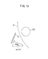
- FIG. 15 illustrates a platen roller assembly released condition
- FIG. 16 shows a perspective view of a portable terminal apparatus including the thermal printer unit shown in FIG. 12 according to the present invention
- FIG. 17 shows a block diagram in connection with first and second photosensors in the portable terminal apparatus shown in FIG. 16 according to the present invention
- FIG. 18 shows a flow chart of operation of a control part shown in FIG. 17;
- FIG. 19 shows a relationship between operation condition of the thermal printer unit and outputs of comparators shown in FIG. 17 according to the present invention
- FIG. 20 shows a block diagram in a variant embodiment in connection with first and second photosensors in the portable terminal apparatus shown in FIG. 16 according to the present invention
- FIGS. 21A and 21B show a first variant embodiment of disposition of the photosensors according to the present invention
- FIGS. 22A and 22B show a second variant embodiment of the disposition of the photosensors according to the present invention.
- FIGS. 23A and 23B show a first variant embodiment of a radiator plate of a thermal head according to the present invention.
- FIG. 24 shows a second variant embodiment of the radiator plate of the thermal head according to the present invention.
- FIGS. 4 and 5 show a line thermal printer unit 40 in a first embodiment of the present invention.
- FIG. 8 shows a line thermal printer 41 including the above-mentioned line thermal printer unit 40 .
- the thermal printer unit 40 includes a thermal head assembly 42 and a platen roller assembly 43 combined therewith.
- X 1 and X 2 denote longitudinal directions of the thermal printer unit 40
- Y 1 and Y 2 denote lateral directions thereof
- Z 1 and Z 2 denote height (thickness) directions thereof.
- the X 1 direction is a front direction of the thermal printer unit 40 while the X 2 direction is a rear direction thereof.
- the thermal head assembly 42 includes a frame 50 , a thermal head 70 mounted in the frame 50 , a head pressing leaf spring 80 , and a paper feeding pulse motor 90 .
- the frame 50 is made by metal die-casting of aluminum or the like, has an outer shape of an approximately rectangular parallelepiped, has side plates 51 and 52 on both sides in the Y 1 and Y 2 directions, and has beams 53 and 54 extending along the Y 1 and Y 2 directions (see FIG. 5 ). Platen roller receiving parts 55 and 56 and thermal head stopper openings 57 and 58 are formed in the side plates 51 and 52 , respectively.
- the platen roller receiving part 55 ( 56 ) is an approximately L-shaped cut-out, has a size corresponding to bearing members 102 and 103 which will be described later, and, as shown in FIG. 6 through magnification, includes a vertical groove part 55 a extending in the Z 2 direction, a horizontal groove part 55 b extending from the bottom of the vertical groove part 55 a in the X 1 direction away from the thermal head 70 , and a projection part 55 d .
- the vertical groove part 55 a has an opening 55 a 1 at the Z 1 -directional end thereof, and a bottom part 55 a 2 at the Z 2 -directional end thereof.
- the horizontal groove part 55 b has an arc-shaped recess part 55 b 1 corresponding to the size of the bearing member 102 at the X 1 -directional end thereof.
- a point 55 c shown in FIG. 6 represents the center of a circle including the outline of the arc-shaped recess part 55 b 1 .
- a straight line 59 shown in FIG. 6 passes through both a rotation shaft 114 of a cover 113 of the line thermal printer 41 shown in FIG. 8 and the above-mentioned center 55 c .
- the directions X 1 a and X 2 a are directions along the above-mentioned straight line 59 .
- This line 59 intersects the outline of the arc-shaped recess 55 b 1 at a point 55 b 1 a.
- the projection part 55 d is formed relatively by the vertical groove part 55 a and horizontal groove part 55 b , is located above the horizontal groove part 55 b and projects from the position of the recess part of the horizontal groove part 55 b in the X 2 direction toward the thermal head 70 .
- the dimension and shape of the projection part 55 d determine a strength of locking of a platen roller.
- the projection part 55 d projects from the point 55 b 1 a by a length A in the X 2 a direction.
- the projecting end of the projection part 55 d has a surface 60 .
- This surface 60 is inclined with respect to the straight line 59 by an angle ⁇ .
- the above-mentioned length A is approximately on the order of 0.4 mm, and the angle ⁇ is approximately 60 degrees.
- the projection part 55 d has, on the Z 1 side thereof, an inclined surface 61 inclined in the direction toward the bottom part 55 a 2 .
- the platen roller receiving part 56 of the other side plate 52 has the same configuration as that of the above-mentioned platen roller receiving part 55 of the side plate 51 .
- the ceramic thermal head 70 is fixed onto a radiator plate 71 .
- the thermal head 70 has heating elements 70 a aligned thereon along the Y 1 -Y 2 directions, and, also, has an end of a flexible cable 72 connected thereto.
- the radiator plate 71 has positioning ear parts 71 a at both ends thereof, as shown in FIG. 5 .
- the head pressing leaf spring 80 includes a body part 81 , a hook part 82 at the top thereof, and leaf spring parts 83 and 84 cut and raised from the body part 81 , as shown in FIGS. 4 and 5.
- the thermal head 70 is incorporated into the frame 50 as a result of the bottom end of the radiator plate 71 being supported by the frame 50 , and the positioning eat parts 71 a thereof being engaged with the thermal head stopper openings 57 and 58 of the side plates 51 and 52 .
- the hook part 82 of the head pressing leaf spring 80 is fitted into the beam part 53 , and the body part 81 thereof is mounted along the X 1 -directional side surface of the beam part 53 , and the leaf spring parts 83 and 84 thereof press the radiator plate 71 in the X 1 direction.
- the positioning ear parts 71 a come into contact with the ends of the thermal head stopper openings 57 and 58 , respectively, and, thereby, the thermal head 70 is positioned.
- the paper feeding pulse motor 90 is mounted on an inner surface of the side plate 52 , as shown in FIG. 4 . Further, a box 92 in which a reduction gear mechanism 91 is incorporated is mounted on an outer surface of the side plate 52 . An opening 93 is formed in the box 92 at a position facing the platen roller receiving part 56 . A gear 94 at an end of the reduction gear mechanism 91 is located at a position adjacent to the opening 93 .
- the platen roller assembly 43 includes the platen roller 100 , a shaft 101 having a Y 2 -end projection part 101 a and a Y 1 -end projection part 10 b, a bearing member 102 mounted to the Y 2 -end projection part 101 a and having a step part 102 a , a bearing member 103 mounted to the Y 1 -end projection part 101 b and having a step part 103 a , and a gear 104 fixed to the Y 1 -end projection part 101 b.
- the bearing member 102 of this platen roller assembly 43 is fitted into the platen roller receiving part 55 , the shaft-receiving part 103 thereof is fitted into the platen roller receiving part 56 , and, thus, the platen roller assembly 43 is hanged between the side plates 51 and 52 of the frame 50 , so that the platen roller assembly 43 is mounted in parallel to the thermal head 70 .
- the gear 104 engages with the gear 94 of the reduction gear mechanism 91 .
- the platen roller 100 pushes back the thermal head 70 slightly in the X 1 direction, as shown in FIGS. 9C and 9D.
- a paper end 21 drawn out from a paper roll 20 lies between the thermal head 70 and platen roller 100 , and, by the elastic force of the head pressing leaf spring 80 , the heating elements 70 a of the thermal head 70 are pressed onto the paper 21 with a force F 10 .
- the force F 10 is a predetermined optimum head pressure.
- An inclination angle ⁇ of the thermal head 70 with respect to the bottom plate 50 e of the frame 50 is approximately 80 degrees, and, thus, is large.
- the thermal head 70 When printing instructions are given to this thermal printer unit 40 , the thermal head 70 is operated, the heating elements 70 a generates heat according to the instructions so as to perform thermal printing on the paper 21 , the pulse motor 90 is driven so as to rotate the platen roller 100 clockwise so that the paper 21 is fed accordingly, and, thus, the thus-printed paper 21 is fed out upward from the thermal printer unit 40 , in FIG. 5 .
- the outer circumferential surface of the platen roller 100 is pressed by the heating elements 70 a of the thermal head 70 with the force F 10 via the paper 21 so that the bearing members 102 and 103 of the platen roller assembly 43 are pressed into the recess parts 55 b 1 of the horizontal groove parts 55 b of the platen roller receiving parts 55 and 56 , respectively. Thereby, the platen roller assembly 43 is locked into and thus prevented from being removed from the platen roller receiving parts 55 and 56 of the frame 50 .
- the bearing members 102 and 103 are not provided and the projection parts 101 a and 101 b of the shaft 101 are directly received by the platen roller receiving parts 55 and 56 . If so, the projection parts 101 a and 101 b of the shaft 101 rotate clockwise when the platen roller 100 rotates clockwise, so that the projection parts 101 a and 101 b roll on the edges of the platen roller receiving parts 55 and 56 . As a result, the projection parts 101 a and 101 b will climb up the edges of the platen roller receiving parts 55 and 56 to go out from the platen roller receiving parts 55 and 56 . However, actually, the bearing members 102 and 103 are provided as mentioned above, and the bearing members 102 and 103 are directly received by the platen roller receiving parts 55 and 56 .
- the platen roller assembly 43 is stably locked in the frame 50 .
- step parts 102 a and 103 a of the bearing parts 102 and 103 come into contact with the outer surfaces of the side plates 51 and 52 . Thereby, the movement of the platen roller 100 along the Y 1 -Y 2 directions is limited. As a result, the platen roller 100 is rotated stably without movement along the axis directions. Thereby, the printed paper 21 is stably fed, and printing on the paper 21 is performed satisfactorily.
- the dimension and shape of the projection part 55 d of each of the platen roller receiving parts 55 and 56 determine the strength of the locking of the platen roller assembly 43 for preventing the platen roller assembly 43 from being removed from the platen roller receiving parts 55 and 56 accidentally.
- FIG. 7A shows the form shown in FIG. 6 .
- the projection part 55 d is configured as a projection part 55 d 1 shown in FIG. 7 B.
- the projection amount of the projection part 55 d 1 is A 1 larger than A of the original projection part 55 d .
- the projection part 55 d is configured as a projection part 55 d 2 shown in FIG. 7 C.
- the projection part 55 d 2 has an angle ⁇ 2 smaller than the angle ⁇ of the original projection part 55 d .
- the projection part 55 d is configured as a projection part 55 d 3 shown in FIG. 7 D.
- the projection amount of the projection part 55 d 3 is A 3 smaller than A of the original projection part 55 d .
- the projection part 55 d is configured as a projection part 55 d 4 shown in FIG. 7 E.
- the projection part 55 d 4 has an angle ⁇ 4 larger than the angle ⁇ of the original projection part 55 d .
- the line thermal printer 41 in one embodiment of the present invention will now be described with reference to FIG. 8 .
- FIG. 8 shows the line thermal printer 41 which is a part of the portable terminal apparatus 110 .
- the line thermal printer 41 is of a clam-shaped type, includes the line thermal printer unit 40 in the first embodiment of the present invention described above, and, further, includes a part for containing the paper roll 20 , and a cover 113 .
- the above-mentioned thermal head assembly 42 is mounted to a base member 111 as a result of legs 50 a and 50 b of the frame 50 being screwed onto the base member 111 .
- a paper roll containing part 112 in which the paper roll 20 is held, is formed.
- the cover 113 is supported at the extending end of the base member 111 by the shaft 114 .
- the above-mentioned platen roller assembly 43 is laterally hanged on the extending end of the cover 113 as a result of both ends thereof being fitted into fork-shaped arm parts 105 and 106 of the cover 113 .
- the platen roller assembly 43 is in a condition such that it can move slightly but cannot be removed from the fork-shaped arm parts 105 and 106 .
- the cover 113 is opened, the paper roll 20 having the paper end 21 thereof unwound therefrom is contained in the paper roll containing part 102 , the unwound paper end 21 is drawn out so as to pass in front of the thermal head 70 , and, then, the cover 113 is closed. Thereby, conditions shown in FIGS. 9A, 9 B and 9 C are passed through, and, then, a condition shown in FIG. 9D in which printing can be properly performed is reached.
- the platen roller assembly 43 moves in the Z 2 direction, as shown in FIGS. 9A and 9B, the bearing members 102 and 103 come into contact with the inclined surfaces 61 of the platen roller receiving parts 55 and 56 , are guided by the surfaces 61 so as to move in the X 2 direction, and then, start to enter the vertical groove parts 55 a via the opening 55 a 1 of the platen roller receiving parts 55 and 56 , respectively.
- the platen roller 100 comes into contact with the thermal head 70 , and pushes it in the X 2 direction, as shown in FIGS. 9B and 9C. Then, as shown in FIG.
- the bearing members 102 and 103 climb over the projection parts 55 d , and enter the vertical groove parts 55 a . Then, as a result of being pressed by the thermal head 70 , the bearing members 102 and 103 are biased in the X 1 direction, as shown in FIG. 9D, are fitted into the horizontal groove parts 55 b , so as to enter below the projection parts 55 d , and thus, the platen roller assembly 43 is locked in the platen roller receiving parts 55 and 56 .
- this line thermal printer 41 a wide space is formed between the thermal head 70 and platen roller 100 when the cover 113 is opened. Accordingly, it is easy to exchange the paper roll 20 . Further, the cover 113 is locked through operation of closing the cover 113 . The lock of the cover 113 is released when the cover 113 is pulled up. Accordingly, any other special locking operation or lock releasing operation is not needed. Accordingly, the printer is convenient in handling thereof.
- the position of the shaft 114 of the cover 113 is determined properly so that a point P (see FIGS. 6 and 9D) at which the heating elements 70 a of the thermal head 70 come into contact with the platen roller 100 is shifted, in a direction (counterclockwise) reverse to a direction (clockwise) in which the platen roller 100 rotates so as to feed the paper 21 , from a point Q at which the straight line 59 passing through the shaft 114 and the center 55 c of the platen roller assembly 43 intersects the circumferential surface of the platen roller 100 on the side of the thermal head 70 .
- the inclination angle ⁇ of the thermal head 70 with respect to the bottom surface of the frame 50 is approximately 80 degrees, and, thus, is large, and a dimension the top end 70 c of the thermal head 70 projects toward the platen roller 100 is short. Accordingly, a shock applied to the top corner 70 c (see FIG. 9B) of the thermal head 70 by the platen roller 100 at the last stage of closing the cover 113 is effectively reduced, and, as a result, the platen roller 100 is not easily harmed thereby.
- the top end of the thermal head 70 may be covered. Thereby, the platen roller 100 can be positively prevented from being harmed by the top end 70 c of the thermal head 70 .
- a protection pad 120 is provided on the radiator plate 71 .
- a curved part 120 a of a protection pad 120 covers the top end 70 c of the thermal head 70 .
- a radiator plate 71 A having an extension part 71 A a curving is provided at the top end thereof. In this case, the curved extension part 71 A a covers the top end 70 c of the thermal head 70 .
- FIG. 10A a protection pad 120 is provided on the radiator plate 71 .
- a radiator plate 71 A having an extension part 71 A a curving is provided at the top end thereof.
- the curved extension part 71 A a covers the top end 70 c of the thermal head 70 .
- a head pressing leaf spring 83 A having an extension part 83 A a curving is provided at the top end thereof.
- the curved extension part 83 A a covers the top end 70 c of the thermal head 70 .
- the platen roller 100 comes into contact with the curved part 120 a, extension part 71 A a or 83 A a so that the platen roller 100 is prevented from directly coming into contact with the top corner 70 c of the thermal head 70 . Accordingly, the platen roller 100 is prevented from being harmed.
- the line thermal printer unit 40 A in the second embodiment has a configuration such that, two photosensors are additionally provided to the line thermal printer unit 40 shown in FIGS. 4 through 7E.
- FIGS. 12 through 14 the same reference numerals are given to components the same as those shown in FIGS. 4 and 5, and the description thereof is omitted.
- the two photosensors i.e., first photosensor 141 and second photosensor 142 are mounted on the top surface of a slender printed substrate 143 near both ends thereof.
- Each of these photosensors 141 and 142 has a configuration in which a light emitting part and a light receiving part receiving light emitted by the light emitting part and reflected by something, side by side.
- the printed substrate 143 is fixed on a bottom side of the beam 54 of the frame 50 .
- the beam 54 has openings 54 a and 54 b formed therein at positions corresponding to the two photosensors 141 and 142 .
- the first photosensor 141 is located in the Y 1 direction while the second photosensor 142 is located in the Y 2 direction.
- the two photosensors 141 and 142 and printed substrate 143 are provided in a space below the beam 54 , and is incorporated into the frame 50 without projecting in the Y 1 and Y 2 directions therefrom. Further, no mechanical switch is provided therein.
- the first photosensor 142 is disposed below the platen roller 100 in the proximity of the Y 2 -directinal end thereof, and, also, thereby, a normal 142 b of a sensor surface 142 a of the photosensor 142 passes through the center axis of the platen roller assembly 43 .
- the photosensor 142 can monitor a range 145 .
- the first photosensor 142 is disposed so as to face the paper 21 in the proximity of the Y 2 -directinal end thereof.
- the second photosensor 141 is disposed below the platen roller 100 in the proximity of the Y 1 -directinal end thereof, and, also, the second photosensor 141 is disposed so as to face the paper 21 in the proximity of the Y 1 -directinal end thereof.
- the flexible cable 72 A has a branch flexible cable part 72 A a in the X 1 direction, branched in the Y 2 direction.
- a terminal part which is an extending end of the branch flexible cable part 72 A a is soldered onto a terminal part on the printed substrate 143 .
- a main part of the flexible cable 72 A is soldered onto a terminal part of the thermal head 70 .
- another branch flexible cable part 72 A b branched in the Y 1 direction is soldered onto a terminal part of the pulse motor 90 . Accordingly, in the line thermal printer unit 40 A, the thermal head 70 , pulse motor 90 , first and second photosensors 141 , 142 and an external circuit are electrically connected together by the single flexible cable 72 A.
- each of the photosensors 141 and 142 outputs a voltage of approximately 5 volts.
- both first and second photosensors 141 and 142 directly face the platen roller 100 .
- the platen roller 100 is made of rubber and thus has a color of gray, it has a low reflectance in surface thereof.
- the output voltage of each of the photosensors 141 and 142 is approximately 3 volts.
- the above-mentioned line thermal printer unit 40 A is used in a condition in which it is incorporated into the portable terminal apparatus 110 A, wherein the above-mentioned first and second photosensors 141 and 142 detect condition of operation of the line thermal printer unit 40 A.
- the terminal part 72 A e at the X 2 -directinal end of the above-mentioned flexible cable 72 A is connected to a connector 162 of a circuit substrate module 161 on which an LSI package 160 and so forth are mounted, included in the portable terminal apparatus 110 A, as shown in FIG. 16 .
- FIG. 17 shows a block diagram of a part of the portable terminal apparatus 110 A in conjunction with the two photosensors 141 and 142 .
- a control circuit 170 To a control circuit 170 , a threshold setting circuit 171 , a thermal head driving circuit 172 , a pulse motor driving circuit 173 and a liquid crystal display device driving part 174 are connected.
- a liquid crystal display device 175 is provided on a top surface of the portable terminal apparatus 110 A, as shown in FIG. 16 .
- the threshold setting circuit 171 includes a comparator 171 - 1 having the non-inverted terminal thereof connected with the first photosensor 141 , and a comparator 171 - 2 having the non-inverted terminal thereof connected with the second photosensor 142 .
- the voltage of 4 volts is applied to the inverted terminal of the comparator 171 - 1 while the voltage of 2 volts is applied to the inverted terminal of the comparator 171 - 2 . Accordingly, the comparator 171 - 1 has a threshold of 4 volts while the compactor 171 - 2 has a threshold of 2 volts.
- the comparator 171 - 1 outputs an L signal when the output voltage of the first photosensor 141 is lower than 4 volts, and outputs an H signal when the output voltage of the first photosensor 141 is equal to or higher than 4 volts.
- the comparator 171 - 2 outputs an L signal when the output voltage of the second photosensor 142 is lower than 2 volts, and outputs an H signal when the output voltage of the second photosensor 142 is equal to or higher than 2 volts.
- the above-mentioned control circuit 170 operates as shown in FIG. 18 .
- a step S 1 it is determined whether or not the comparator 171 - 1 outputs the L signal.
- the comparator 171 - 1 outputs the L signal
- it is determined in a step S 3 whether or not the comparator 171 - 2 outputs the H signal.
- a signal for displaying that it is the normal condition is output to the liquid crystal display device driving circuit 174 in a step S 4 .
- a thermal head stopping signal is output to the thermal head driving circuit 172 in a step S 5
- a pulse motor stopping signal is output to the pulse motor driving circuit 173 in a step S 6
- a signal for displaying that it is the platen roller assembly released condition is output to the liquid crystal display device driving circuit 174 in a step S 7 .
- a signal for displaying that it is the paper near end condition is output to the liquid crystal display device driving circuit 174 in a step S 8 .
- the thermal head stopping signal is output to the thermal head driving circuit 172 in a step S 9
- the pulse motor stopping signal is output to the pulse motor driving circuit 173 in a step S 10
- a signal for displaying that it is the paper end condition is output to the liquid crystal display device driving circuit 174 in a step S 11 .
- FIG. 19 shows relationship between the outputs of the comparators 171 - 1 and 171 - 2 and the condition of the line thermal printer unit 40 A.
- the liquid crystal display device 175 displays that it is the normal condition.
- comparator 171 - 1 When the comparator 171 - 1 outputs the L signal and comparator 171 - 2 also outputs the L signal, the driving of the thermal head 70 is stopped, the driving of the pulse motor 90 is stopped, and the display device 175 displays that it is the platen roller assembly released condition.
- FIG. 20 shows a block diagram of a variant embodiment of the part of the portable terminal apparatus 110 A in conjunction with the two photosensors 141 and 142 .
- both comparators 171 - 1 and 171 - 2 have the same threshold (2.5 volts) in a threshold setting circuit 171 B. Then, a circuit 180 for setting the sensitivities of the first and second photosensors 141 and 142 is additionally provided.
- This circuit 180 includes resistors R 1 having a same resistance r 1 which are connected to the light emitting parts 141 a and 142 a of the photosensors 141 and 142 , respectively. Further, a resistor R 2 having a resistance r 2 is connected to the light receiving part 141 b of the first photosensor 141 while a resistor R 3 having a resistance r 3 larger than the resistance r 2 (r 3 >r 2 ) is connected to the light receiving part 142 b of the second photosensor 142 .
- the output voltages taken between the light receiving parts 141 b and 142 b and the resistors R 2 and R 3 , respectively, are such as those obtained as if the second photosensor 142 has a sensitivity higher than that of the first photosensor 141 . Accordingly, when both photosensors 141 and 142 face the gray-colored platen roller 100 , the output voltage of the first photosensor 141 is lower than the threshold (2.5 volts) while the output voltage of the second photosensor 142 is higher than the threshold (2.5 volts). As a result, the relationship between the outputs of the comparators 171 - 1 and 171 - 2 and the condition of the line thermal printer unit 40 A is the same as that shown in FIG. 19 .
- FIGS. 21A and 21B show a first variant embodiment of the displacement of the photosensors 141 and 142 of the above-mentioned line thermal printer unit 40 A.
- a platen roller 100 C has a color of white at an Y 2 -directinal portion thereof, as shown in FIG. 21A, and, as shown in the figure, the photosensors 141 and 142 are disposed to face a portion near the Y 1 -directional end of the platen roller 100 C.
- the photosensors 141 and 142 are mounted on a terminal circuit substrate 190 of the pulse motor 90 . Thus, it is not necessary to provide any other member especially for mounting the photosensors 141 and 142 .
- This platen roller 100 C is manufactured through two-color mold of rubber, and includes a gray-colored portion 100 C a and a white-colored portion 100 C b.
- the first photosensor 141 faces the gray-colored portion 100 C a while the second photosensor 142 faces the white-colored portion 100 C b. Accordingly, when the paper 21 has been completely run out (paper end condition), the second photosensor 142 maintains to output 5 volts.
- the threshold setting circuit 171 shown in FIG. 17 is used in which 4 volts is set as the threshold for the comparator 171 - 1 while 2 volts is set as the threshold for the comparator 171 - 2 .
- the first photosensor 141 is connected to the comparator 171 - 2 while the second photosensor 142 is connected to the comparator 171 - 1 , as shown in FIG. 21 A.
- the black-painted part 21 a shown in FIG. 16 is provided at the Y 1 -directional end instead of the Y 2 -directinal end. Accordingly, the relationship between the outputs of the comparators 171 - 1 and 171 - 2 and the condition of the line thermal printer unit 40 A is the same as that shown in FIG. 19 .
- the photosensors 141 and 142 are mounted on the terminal circuit substrate 190 of the pulse motor 90 and no additional member is needed for mounting the photosensors 141 and 142 . Accordingly, it is possible to reduce the number of necessary components. Also, it is possible to achieve mounting of the sensors 141 and 142 within a small space. Furthermore, the flexible cable such as that shown in FIG. 14 having a complex shape is not needed. Specifically, the branch part 72 A a is not needed. Accordingly, it is possible to simplify the shape of the flexible cable, and to achieve simpler wiring.
- FIGS. 22A and 22B show a second variant embodiment of the disposition of the photosensors 141 and 142 .
- the two photosensors 141 and 142 are mounted on a circuit substrate 143 D at diagonal positions, as shown in FIG. 22 B.
- the second photosensor 142 is located in the Y 2 direction and faces the platen roller 100 while the first photosensor 141 is located in the Y 1 direction and is shifted from a position of facing the platen roller 100 .
- the second photosensor 142 faces the above-mentioned black-painted part 21 a while the first photosensor 141 faces a normal white portion of the paper 21 . Accordingly, the second photosensor 142 outputs approximately 0 volts while the first photosensor 141 outputs approximately 5 volts. Then, in the paper end condition, in which the paper 21 has moved upward in FIG.
- the second photosensor 142 outputs approximately 5 volts (and then approximately 3 volts after the end edge of the paper 21 passes by the second photosensor 142 also) while the first photosensor 141 outputs approximately 0 volts.
- each of the comparators 171 - 1 and 171 - 2 has the same threshold (2.5 volts) in a threshold setting circuit 171 B, as shown in FIG. 22 B. Further, the two photosensors 141 and 142 have the same sensitivity. In these conditions, the relationship between the outputs of the comparators 171 - 1 and 171 - 2 and the condition of the line thermal printer unit 40 A is the same as that shown in FIG. 19 .
- FIGS. 23A and 23B show a first variant embodiment of the above-mentioned radiator plate 71 .
- a radiator plate 200 in the first variant embodiment is made of metal, and, has head pressing leaf springs 202 integrated with a radiator plate body 201 .
- the head pressing leaf springs 202 are formed as a result of portions 203 extending from the radiator plate body 201 being bent through press work.
- This radiator plate 200 has both a function as a radiator and a function as a head pressing leaf spring.
- This radiator plate 200 is incorporated into the line thermal printer unit 40 A as shown in FIG. 23 B. In this configuration, no other separate members are needed for providing the function of head pressing leaf springs. Accordingly, it is possible to reduce the number of necessary components.
- FIG. 24 shows a second variant embodiment of the radiator plate 71 .
- a radiator plate 210 in the second variant embodiment has conic-coil-spring-shaped head pressing leaf springs 212 formed as a result of spiral strips formed in a radiator plate body 211 being pressed out.
Landscapes
- Electronic Switches (AREA)
- Handling Of Sheets (AREA)
- Common Mechanisms (AREA)
Applications Claiming Priority (4)
| Application Number | Priority Date | Filing Date | Title |
|---|---|---|---|
| JP2000240477 | 2000-08-08 | ||
| JP2000-240477 | 2000-08-08 | ||
| JP2000-306725 | 2000-10-05 | ||
| JP2000306725A JP4675469B2 (ja) | 2000-08-08 | 2000-10-05 | サーマルプリンタユニット及びサーマルプリンタ装置 |
Publications (2)
| Publication Number | Publication Date |
|---|---|
| US20020021927A1 US20020021927A1 (en) | 2002-02-21 |
| US6682239B2 true US6682239B2 (en) | 2004-01-27 |
Family
ID=26597589
Family Applications (1)
| Application Number | Title | Priority Date | Filing Date |
|---|---|---|---|
| US09/881,739 Expired - Lifetime US6682239B2 (en) | 2000-08-08 | 2001-06-18 | Thermal printer unit and thermal printer |
Country Status (4)
| Country | Link |
|---|---|
| US (1) | US6682239B2 (de) |
| EP (1) | EP1179433B1 (de) |
| JP (1) | JP4675469B2 (de) |
| DE (1) | DE60109370T2 (de) |
Cited By (16)
| Publication number | Priority date | Publication date | Assignee | Title |
|---|---|---|---|---|
| US20040061769A1 (en) * | 2002-09-30 | 2004-04-01 | Fujitsu Limited | Thermal printer and portable-type terminal equipment |
| US20040141049A1 (en) * | 2002-12-23 | 2004-07-22 | Burdenko Michael N. | Roller assembly |
| US20040174423A1 (en) * | 2003-03-03 | 2004-09-09 | Nec Infrontia Corporation | Method of printing data on sheet |
| US20050041090A1 (en) * | 2003-03-03 | 2005-02-24 | Nec Infrontia Corporation | Printing system using thermal printer |
| US20060017221A1 (en) * | 2004-07-09 | 2006-01-26 | Funai Electric Co., Ltd. | Image forming apparatus |
| US20060115311A1 (en) * | 2004-11-26 | 2006-06-01 | Samsung Electronics Co., Ltd. | Thermal image forming apparatus |
| US20060176360A1 (en) * | 2002-03-21 | 2006-08-10 | Aps Engineering | Thermal printing mechanism, in particularly applicable to payment terminals |
| US20060216096A1 (en) * | 2005-03-25 | 2006-09-28 | Funai Electric Co., Ltd. | Image forming device |
| US20060291933A1 (en) * | 2005-06-22 | 2006-12-28 | Fujitsu Components Limited | Printing apparatus |
| US20090154949A1 (en) * | 2006-03-06 | 2009-06-18 | Marcelo Filipak | Printer with modular cartridge |
| US20090219375A1 (en) * | 2006-03-06 | 2009-09-03 | Ricardo Trauer | Thermal printer |
| US20100253759A1 (en) * | 2009-04-01 | 2010-10-07 | Fujitsu Component Limited | Thermal printer |
| US20110279620A1 (en) * | 2010-05-17 | 2011-11-17 | Silverbrook Research Pty Ltd. | System for aligning driven and idler rollers in printer |
| US20120327165A1 (en) * | 2011-06-21 | 2012-12-27 | Fujitsu Component Limited | Thermal printer |
| US20140232806A1 (en) * | 2011-10-07 | 2014-08-21 | Fujitsu Component Limited | Printer |
| US11325405B2 (en) * | 2019-01-29 | 2022-05-10 | Fujitsu Component Limited | Printer with print head and support having head spring that urges print head |
Families Citing this family (20)
| Publication number | Priority date | Publication date | Assignee | Title |
|---|---|---|---|---|
| JP4394923B2 (ja) | 2003-10-29 | 2010-01-06 | 富士通コンポーネント株式会社 | プリンタ |
| JP5196719B2 (ja) | 2005-10-25 | 2013-05-15 | 富士通コンポーネント株式会社 | サーマルプリンタ |
| US7270494B2 (en) * | 2005-12-05 | 2007-09-18 | Silverbrook Research Pty Ltd | Easy assembly printer media transport arrangement |
| JP2007331112A (ja) | 2006-06-12 | 2007-12-27 | Seiko Epson Corp | サーマルプリンタ |
| JP5012556B2 (ja) * | 2007-03-15 | 2012-08-29 | セイコーエプソン株式会社 | 印刷装置 |
| JP5171084B2 (ja) * | 2007-03-26 | 2013-03-27 | 富士通コンポーネント株式会社 | プリンタ及び、それを組み込んだ携帯型端末装置 |
| JP5159244B2 (ja) | 2007-10-24 | 2013-03-06 | シチズン・システムズ株式会社 | サーマルプリンタ |
| JP4936335B2 (ja) * | 2007-12-28 | 2012-05-23 | シチズン・システムズ株式会社 | プリンタ |
| JP5270321B2 (ja) * | 2008-12-05 | 2013-08-21 | 富士通コンポーネント株式会社 | プリンタモジュール |
| US8305410B2 (en) * | 2009-06-19 | 2012-11-06 | Fujitsu Component Limited | Thermal head unit and thermal printer with driver IC on flexible substrate |
| JP5977516B2 (ja) * | 2011-12-26 | 2016-08-24 | 富士通コンポーネント株式会社 | プリンタ装置 |
| JP5172025B2 (ja) * | 2012-02-20 | 2013-03-27 | 富士通コンポーネント株式会社 | プリンタ及び、それを組み込んだ携帯型端末装置 |
| JP6145375B2 (ja) * | 2013-09-27 | 2017-06-14 | セイコーインスツル株式会社 | サーマルプリンタ |
| JP6196550B2 (ja) * | 2013-12-26 | 2017-09-13 | 富士通コンポーネント株式会社 | プリンタ装置及びプリンタ装置の制御方法 |
| JP6411071B2 (ja) * | 2014-05-30 | 2018-10-24 | 富士通コンポーネント株式会社 | プリンタ装置 |
| JP6829008B2 (ja) | 2016-05-24 | 2021-02-10 | 富士通コンポーネント株式会社 | プリンタ |
| JP6767189B2 (ja) * | 2016-07-26 | 2020-10-14 | セイコーインスツル株式会社 | サーマルプリンタ及び携帯型端末 |
| JP7588500B2 (ja) * | 2020-11-30 | 2024-11-22 | セイコーインスツル株式会社 | 印字ユニットおよび携帯型端末 |
| CN113771502B (zh) * | 2021-09-15 | 2023-01-13 | 河南印都数码科技有限公司 | 双头单辊条幅打印装置 |
| JP2023081504A (ja) * | 2021-12-01 | 2023-06-13 | セイコーインスツル株式会社 | 印字ユニットおよび携帯型端末 |
Citations (14)
| Publication number | Priority date | Publication date | Assignee | Title |
|---|---|---|---|---|
| JPS5916458A (ja) | 1982-07-20 | 1984-01-27 | Canon Inc | ロ−ル状シ−トの終端検知装置 |
| US4778296A (en) | 1986-10-30 | 1988-10-18 | Brother Kogyo Kabushiki Kaisha | Paper check device for a printer |
| JPH01222980A (ja) | 1988-03-02 | 1989-09-06 | Fujitsu Ltd | サーマルプリンタ及びそれに用いる2ply感熱紙 |
| JPH02160558A (ja) | 1988-12-14 | 1990-06-20 | Tokyo Electric Co Ltd | ラインサーマルプリンタ |
| JPH04249184A (ja) | 1991-02-01 | 1992-09-04 | Matsushita Graphic Commun Syst Inc | 走査ヘッド |
| JPH05212923A (ja) * | 1992-02-04 | 1993-08-24 | Sony Corp | 感熱記録装置 |
| JPH05238597A (ja) | 1992-02-25 | 1993-09-17 | Canon Inc | 記録装置 |
| EP0572700A1 (de) * | 1992-06-04 | 1993-12-08 | Samsung Electronics Co., Ltd. | Papierhalter für einen Videodrucker |
| US5579043A (en) * | 1992-11-06 | 1996-11-26 | Axiohm | Openable thermal printer |
| JPH09323454A (ja) | 1996-06-05 | 1997-12-16 | Seiko Epson Corp | 記録紙の装填確認方法及びサーマルプリンタ |
| JPH10258532A (ja) | 1997-03-19 | 1998-09-29 | Hitachi Ltd | 感熱式プリンタ |
| US6004053A (en) | 1998-09-11 | 1999-12-21 | Comtec Informationsystems, Inc. | Printer apparatus |
| JP2000085168A (ja) | 1998-09-08 | 2000-03-28 | Aoi Denshi Kk | サーマルヘッド、サーマルヘッドの作製方法及びプリンタ |
| JP2000272201A (ja) * | 1999-03-25 | 2000-10-03 | Seiko Epson Corp | プリンタ |
Family Cites Families (1)
| Publication number | Priority date | Publication date | Assignee | Title |
|---|---|---|---|---|
| JPH10147023A (ja) * | 1996-09-19 | 1998-06-02 | Seiko Epson Corp | サーマルプリンタ |
-
2000
- 2000-10-05 JP JP2000306725A patent/JP4675469B2/ja not_active Expired - Fee Related
-
2001
- 2001-06-18 US US09/881,739 patent/US6682239B2/en not_active Expired - Lifetime
- 2001-06-20 EP EP01305351A patent/EP1179433B1/de not_active Expired - Lifetime
- 2001-06-20 DE DE60109370T patent/DE60109370T2/de not_active Expired - Lifetime
Patent Citations (14)
| Publication number | Priority date | Publication date | Assignee | Title |
|---|---|---|---|---|
| JPS5916458A (ja) | 1982-07-20 | 1984-01-27 | Canon Inc | ロ−ル状シ−トの終端検知装置 |
| US4778296A (en) | 1986-10-30 | 1988-10-18 | Brother Kogyo Kabushiki Kaisha | Paper check device for a printer |
| JPH01222980A (ja) | 1988-03-02 | 1989-09-06 | Fujitsu Ltd | サーマルプリンタ及びそれに用いる2ply感熱紙 |
| JPH02160558A (ja) | 1988-12-14 | 1990-06-20 | Tokyo Electric Co Ltd | ラインサーマルプリンタ |
| JPH04249184A (ja) | 1991-02-01 | 1992-09-04 | Matsushita Graphic Commun Syst Inc | 走査ヘッド |
| JPH05212923A (ja) * | 1992-02-04 | 1993-08-24 | Sony Corp | 感熱記録装置 |
| JPH05238597A (ja) | 1992-02-25 | 1993-09-17 | Canon Inc | 記録装置 |
| EP0572700A1 (de) * | 1992-06-04 | 1993-12-08 | Samsung Electronics Co., Ltd. | Papierhalter für einen Videodrucker |
| US5579043A (en) * | 1992-11-06 | 1996-11-26 | Axiohm | Openable thermal printer |
| JPH09323454A (ja) | 1996-06-05 | 1997-12-16 | Seiko Epson Corp | 記録紙の装填確認方法及びサーマルプリンタ |
| JPH10258532A (ja) | 1997-03-19 | 1998-09-29 | Hitachi Ltd | 感熱式プリンタ |
| JP2000085168A (ja) | 1998-09-08 | 2000-03-28 | Aoi Denshi Kk | サーマルヘッド、サーマルヘッドの作製方法及びプリンタ |
| US6004053A (en) | 1998-09-11 | 1999-12-21 | Comtec Informationsystems, Inc. | Printer apparatus |
| JP2000272201A (ja) * | 1999-03-25 | 2000-10-03 | Seiko Epson Corp | プリンタ |
Cited By (31)
| Publication number | Priority date | Publication date | Assignee | Title |
|---|---|---|---|---|
| US7417658B2 (en) * | 2002-03-21 | 2008-08-26 | Aps Engineering | Thermal printing mechanism, in particularly applicable to payment terminals |
| US20060176360A1 (en) * | 2002-03-21 | 2006-08-10 | Aps Engineering | Thermal printing mechanism, in particularly applicable to payment terminals |
| US7154521B2 (en) * | 2002-09-30 | 2006-12-26 | Fujitsu Limited | Thermal printer and portable-type terminal equipment |
| US20040061769A1 (en) * | 2002-09-30 | 2004-04-01 | Fujitsu Limited | Thermal printer and portable-type terminal equipment |
| US20040141049A1 (en) * | 2002-12-23 | 2004-07-22 | Burdenko Michael N. | Roller assembly |
| US20050286959A1 (en) * | 2002-12-23 | 2005-12-29 | Polaroid Corporation | Roller assembly |
| US7086795B2 (en) * | 2002-12-23 | 2006-08-08 | Zink Imaging, Llc | Roller assembly |
| US20040174423A1 (en) * | 2003-03-03 | 2004-09-09 | Nec Infrontia Corporation | Method of printing data on sheet |
| US20050041090A1 (en) * | 2003-03-03 | 2005-02-24 | Nec Infrontia Corporation | Printing system using thermal printer |
| US6927787B2 (en) * | 2003-03-03 | 2005-08-09 | Nec Infrontia Corporation | Method of printing data on sheet |
| US7030896B2 (en) * | 2003-03-03 | 2006-04-18 | Nec Infrontia Corporation | Printing system using thermal printer |
| US20060017221A1 (en) * | 2004-07-09 | 2006-01-26 | Funai Electric Co., Ltd. | Image forming apparatus |
| US20060115311A1 (en) * | 2004-11-26 | 2006-06-01 | Samsung Electronics Co., Ltd. | Thermal image forming apparatus |
| US7367726B2 (en) * | 2004-11-26 | 2008-05-06 | Samsung Electronics Co., Ltd. | Thermal image forming apparatus |
| US7121748B1 (en) * | 2005-03-25 | 2006-10-17 | Funai Electric Co., Ltd. | Image forming device |
| US20060216096A1 (en) * | 2005-03-25 | 2006-09-28 | Funai Electric Co., Ltd. | Image forming device |
| US20060291933A1 (en) * | 2005-06-22 | 2006-12-28 | Fujitsu Components Limited | Printing apparatus |
| US8419302B2 (en) * | 2005-06-22 | 2013-04-16 | Fujitsu Component Limited | Printing apparatus |
| US20090219375A1 (en) * | 2006-03-06 | 2009-09-03 | Ricardo Trauer | Thermal printer |
| US7936366B2 (en) | 2006-03-06 | 2011-05-03 | Bematech Industria E Comercio De Equipamentos Electronics S/A | Thermal printer |
| US20090154949A1 (en) * | 2006-03-06 | 2009-06-18 | Marcelo Filipak | Printer with modular cartridge |
| US8425130B2 (en) | 2006-03-06 | 2013-04-23 | Bematech S.A. | Printer with modular cartridge |
| US20100253759A1 (en) * | 2009-04-01 | 2010-10-07 | Fujitsu Component Limited | Thermal printer |
| US8189025B2 (en) * | 2009-04-01 | 2012-05-29 | Fujitsu Component Limited | Thermal printer |
| US8783845B2 (en) * | 2010-05-17 | 2014-07-22 | Memjet Technology Ltd. | System for aligning driven and idler rollers in printer |
| US20110279620A1 (en) * | 2010-05-17 | 2011-11-17 | Silverbrook Research Pty Ltd. | System for aligning driven and idler rollers in printer |
| US20120327165A1 (en) * | 2011-06-21 | 2012-12-27 | Fujitsu Component Limited | Thermal printer |
| US8659632B2 (en) * | 2011-06-21 | 2014-02-25 | Fujitsu Component Limited | Thermal printer |
| US20140232806A1 (en) * | 2011-10-07 | 2014-08-21 | Fujitsu Component Limited | Printer |
| US9186904B2 (en) * | 2011-10-07 | 2015-11-17 | Fujitsu Component Limited | Printer |
| US11325405B2 (en) * | 2019-01-29 | 2022-05-10 | Fujitsu Component Limited | Printer with print head and support having head spring that urges print head |
Also Published As
| Publication number | Publication date |
|---|---|
| EP1179433B1 (de) | 2005-03-16 |
| JP2002120389A (ja) | 2002-04-23 |
| DE60109370T2 (de) | 2005-09-29 |
| EP1179433A2 (de) | 2002-02-13 |
| DE60109370D1 (de) | 2005-04-21 |
| JP4675469B2 (ja) | 2011-04-20 |
| EP1179433A3 (de) | 2002-04-17 |
| US20020021927A1 (en) | 2002-02-21 |
Similar Documents
| Publication | Publication Date | Title |
|---|---|---|
| US6682239B2 (en) | Thermal printer unit and thermal printer | |
| US8419302B2 (en) | Printing apparatus | |
| JP4045029B2 (ja) | プリンタ | |
| US8011844B2 (en) | Printer having detecting arm for detecting near-end state of paper roll | |
| US5302034A (en) | Printing device for printing image on tape like member | |
| JP5108072B2 (ja) | 印字装置 | |
| JP5790020B2 (ja) | サーマルヘッド機構、サーマルプリンターユニット及びサーマルプリンター | |
| US20150319321A1 (en) | Image forming apparatus having co-planar top cover and operation panel | |
| JP2001150777A (ja) | 印字装置におけるカセット収納検出装置及びカセット | |
| JP2013131725A (ja) | 電子装置、検出モジュール、及びフレキシブルプリント回路基板 | |
| CN114571870B (zh) | 印字单元和便携型终端 | |
| US10525748B2 (en) | Unit attaching structure and printing device | |
| US7580249B2 (en) | Image forming apparatus | |
| CN219065985U (zh) | 曝光装置及打印机 | |
| US6646667B1 (en) | Thermal printer | |
| US20240351814A1 (en) | Paper conveying device | |
| KR200212894Y1 (ko) | 감열기록지 풀림 방지장치 | |
| JP2001260447A (ja) | カセット | |
| JP3322483B2 (ja) | 印字テープ作成装置におけるカセット収納部のカバー装置 | |
| JP2003145852A (ja) | サーマルプリンタ | |
| JP2004262588A (ja) | ロール紙装着装置及びそれを用いたプリンタ | |
| JP2003320724A (ja) | ロール紙装着装置及びそれを用いたプリンタ | |
| JP2008072544A (ja) | 画像形成装置 | |
| JPH07172028A (ja) | 画像記録装置 | |
| JP2001343715A (ja) | 開閉体の開閉状態検知機構 |
Legal Events
| Date | Code | Title | Description |
|---|---|---|---|
| AS | Assignment |
Owner name: FUJITSU TAKAMISAWA COMPONENT LIMITED, JAPAN Free format text: ASSIGNMENT OF ASSIGNORS INTEREST;ASSIGNORS:MORI, YUKIHIRO;OHTSUKA, HIMORMI;REEL/FRAME:011916/0233 Effective date: 20010608 |
|
| AS | Assignment |
Owner name: FUJITSU TAKAMISAWA COMPONENT LIMITED, JAPAN Free format text: CORRECTED RECORDATION FORM COVER SHEET REEL/FRAME O11916/O233;ASSIGNORS:MORI, YUKIHIRO;OHTSUKA, HIROMI;REEL/FRAME:012209/0973 Effective date: 20010608 |
|
| STCF | Information on status: patent grant |
Free format text: PATENTED CASE |
|
| CC | Certificate of correction | ||
| FPAY | Fee payment |
Year of fee payment: 4 |
|
| FPAY | Fee payment |
Year of fee payment: 8 |
|
| FPAY | Fee payment |
Year of fee payment: 12 |