US6669398B2 - Locking structure for connector - Google Patents
Locking structure for connector Download PDFInfo
- Publication number
- US6669398B2 US6669398B2 US09/797,809 US79780901A US6669398B2 US 6669398 B2 US6669398 B2 US 6669398B2 US 79780901 A US79780901 A US 79780901A US 6669398 B2 US6669398 B2 US 6669398B2
- Authority
- US
- United States
- Prior art keywords
- lock
- connector housing
- disengaging
- latch
- connector
- Prior art date
- Legal status (The legal status is an assumption and is not a legal conclusion. Google has not performed a legal analysis and makes no representation as to the accuracy of the status listed.)
- Expired - Lifetime, expires
Links
Images




Classifications
-
- C—CHEMISTRY; METALLURGY
- C08—ORGANIC MACROMOLECULAR COMPOUNDS; THEIR PREPARATION OR CHEMICAL WORKING-UP; COMPOSITIONS BASED THEREON
- C08J—WORKING-UP; GENERAL PROCESSES OF COMPOUNDING; AFTER-TREATMENT NOT COVERED BY SUBCLASSES C08B, C08C, C08F, C08G or C08H
- C08J9/00—Working-up of macromolecular substances to porous or cellular articles or materials; After-treatment thereof
- C08J9/0004—Use of compounding ingredients, the chemical constitution of which is unknown, broadly defined, or irrelevant
-
- H—ELECTRICITY
- H01—ELECTRIC ELEMENTS
- H01R—ELECTRICALLY-CONDUCTIVE CONNECTIONS; STRUCTURAL ASSOCIATIONS OF A PLURALITY OF MUTUALLY-INSULATED ELECTRICAL CONNECTING ELEMENTS; COUPLING DEVICES; CURRENT COLLECTORS
- H01R13/00—Details of coupling devices of the kinds covered by groups H01R12/70 or H01R24/00 - H01R33/00
- H01R13/62—Means for facilitating engagement or disengagement of coupling parts or for holding them in engagement
- H01R13/627—Snap or like fastening
- H01R13/6271—Latching means integral with the housing
- H01R13/6272—Latching means integral with the housing comprising a single latching arm
-
- C—CHEMISTRY; METALLURGY
- C08—ORGANIC MACROMOLECULAR COMPOUNDS; THEIR PREPARATION OR CHEMICAL WORKING-UP; COMPOSITIONS BASED THEREON
- C08J—WORKING-UP; GENERAL PROCESSES OF COMPOUNDING; AFTER-TREATMENT NOT COVERED BY SUBCLASSES C08B, C08C, C08F, C08G or C08H
- C08J2300/00—Characterised by the use of unspecified polymers
- C08J2300/14—Water soluble or water swellable polymers, e.g. aqueous gels
-
- Y—GENERAL TAGGING OF NEW TECHNOLOGICAL DEVELOPMENTS; GENERAL TAGGING OF CROSS-SECTIONAL TECHNOLOGIES SPANNING OVER SEVERAL SECTIONS OF THE IPC; TECHNICAL SUBJECTS COVERED BY FORMER USPC CROSS-REFERENCE ART COLLECTIONS [XRACs] AND DIGESTS
- Y10—TECHNICAL SUBJECTS COVERED BY FORMER USPC
- Y10T—TECHNICAL SUBJECTS COVERED BY FORMER US CLASSIFICATION
- Y10T292/00—Closure fasteners
- Y10T292/08—Bolts
- Y10T292/0911—Hooked end
- Y10T292/0926—Spring projected
- Y10T292/0928—Operating means
- Y10T292/0934—Rigid
-
- Y—GENERAL TAGGING OF NEW TECHNOLOGICAL DEVELOPMENTS; GENERAL TAGGING OF CROSS-SECTIONAL TECHNOLOGIES SPANNING OVER SEVERAL SECTIONS OF THE IPC; TECHNICAL SUBJECTS COVERED BY FORMER USPC CROSS-REFERENCE ART COLLECTIONS [XRACs] AND DIGESTS
- Y10—TECHNICAL SUBJECTS COVERED BY FORMER USPC
- Y10T—TECHNICAL SUBJECTS COVERED BY FORMER US CLASSIFICATION
- Y10T403/00—Joints and connections
- Y10T403/59—Manually releaseable latch type
- Y10T403/591—Manually releaseable latch type having operating mechanism
- Y10T403/595—Lever
-
- Y—GENERAL TAGGING OF NEW TECHNOLOGICAL DEVELOPMENTS; GENERAL TAGGING OF CROSS-SECTIONAL TECHNOLOGIES SPANNING OVER SEVERAL SECTIONS OF THE IPC; TECHNICAL SUBJECTS COVERED BY FORMER USPC CROSS-REFERENCE ART COLLECTIONS [XRACs] AND DIGESTS
- Y10—TECHNICAL SUBJECTS COVERED BY FORMER USPC
- Y10T—TECHNICAL SUBJECTS COVERED BY FORMER US CLASSIFICATION
- Y10T403/00—Joints and connections
- Y10T403/60—Biased catch or latch
- Y10T403/606—Leaf spring
-
- Y—GENERAL TAGGING OF NEW TECHNOLOGICAL DEVELOPMENTS; GENERAL TAGGING OF CROSS-SECTIONAL TECHNOLOGIES SPANNING OVER SEVERAL SECTIONS OF THE IPC; TECHNICAL SUBJECTS COVERED BY FORMER USPC CROSS-REFERENCE ART COLLECTIONS [XRACs] AND DIGESTS
- Y10—TECHNICAL SUBJECTS COVERED BY FORMER USPC
- Y10T—TECHNICAL SUBJECTS COVERED BY FORMER US CLASSIFICATION
- Y10T403/00—Joints and connections
- Y10T403/60—Biased catch or latch
- Y10T403/608—Pivoted
Definitions
- the present invention relates to a locking structure for a connector.
- FIG. 15A is a sectional view of an essential part.
- FIG. 15B is a view as seen in a direction of an arrow A of FIG. 15A, and
- FIG. 15C is a view as seen in a direction of an arrow B of FIG. 15 A.
- a female connector housing 201 is provided with a lock arm 203 having elasticity, and the lock arm 203 has a hook portion 205 at its distal end.
- a male connector housing 207 is inserted into the female connector housing 201 , an engaging portion 209 of the male connector housing 207 pushes the hook portion 205 of the lock arm 203 upward, and a support portion 211 of the lock arm 203 is flexed to bring the lock arm 203 into a posture as shown by a dotted line in FIG. 15 A.
- the lock arm 203 is restored from the deformed posture allowing both the connector housings 201 and 207 to be locked.
- a backward end portion 213 of the lock arm 203 is pushed down to bring the hook portion 205 of the lock arm 203 into a pushed up state in the same manner as done when the male connector housing 207 has been inserted, thereby disengaging the lock of the hook portion 205 .
- the lock arm 203 is designed in such a manner that when the lock arm 203 is inclined by an angle ⁇ as shown in FIG. 15A, projections 215 formed on both side ends of the lock arm 203 in a lateral direction come in contact with stoppers 217 , thereby to restrict an amount of flexure of the support portion 211 .
- the lock arm 203 is so constructed that an area from the hook portion 205 of the lock arm 203 to the backward end portion 213 has high rigidity lacking in flexibility, and flexible areas are concentrated on the support portion 211 only.
- a thickness of the support portion 211 may be increased.
- operating force for disengaging the lock will be increased accordingly, which results in an increase of a stress on the support portion 211 , and the support portion 211 will be likely to be broken.
- material having less rigidity may be employed without changing a shape, but tendency of the breakage will not be improved.
- an object of the present invention is to provide a lock structure in which flexure of a locking member can be dispersed, and in addition, which has sufficient strength and is difficult to be broken.
- the present invention is a locking structure for a connector which is adapted to disengageably lock a male connector housing and a female connector housing which are adapted to be engaged with each other by locking an engaging portion provided on one of the housings with a latch portion provided on the other of the housings, characterized in that the other connector housing includes the latch portion at an opposite side of flexible arms which are fixed at their one ends on a wall of the housing so as to extend in an engaging direction of the housings, and a disengaging lever portion which is connected at its one end to the latch portion so as to extend along the arms, and the disengaging lever portion rotates with the latch portion around a pivot which is movable when the lock is disengaged.
- a member resisting to displacement of the latch portion when both the housings are engaged is only the arms in a cantilever type, and by appropriately setting a length and a thickness of the arms for example, the arms are uniformly flexed along their full length. Since a stress will not be concentrated on base end portions of the arms, a flexural angle at the fixed ends of the arms is thus limited to be small, enabling the arms to be less breakable.
- the latch portion rotates around the pivot together with the disengaging lever portion, whereby the locked condition will be disengaged.
- the pivot of the rotation can be displaced, the latch portion can rotate without resistance, and the arms which have been in the flexed state will not be subjected to an undue load. Therefore, the problem of shortage of strength will not happen.
- a locking structure for the connector as described above and characterized in that at least one of the disengaging lever portion and the wall of the housing has a support portion which serves as the pivot of the rotation of the latch portion.
- a locking structure for the connector as described above and characterized in that the pivot of the rotation is provided at either one of a substantially same position as the fixed ends of the flexible arms in the engaging direction, and a position on a lock disengaging operation section.
- a locking structure for the connector as described above and characterized in that the disengaging lever portion includes the lock disengaging operation section at an opposite side to the latch portion interposing the support portion, and a distance between the support portion and the latch portion is set to be larger than a distance between the support portion and the lock disengaging operation section.
- a locking structure for the connector as described above and characterized in that the disengaging lever portion is connected to the connector housing by means of a hinge at an opposite side to the latch portion interposing the pivot.
- a locking structure for the connector as described above and characterized in that the locking structure further includes lever side excessive displacement preventing pieces provided on both sides of a finger touch portion which is positioned at an opposite side to the latch portion, and housing side excessive displacement preventing pieces provided on the female connector housing and against which the lever side excessive displacement preventing pieces are adapted to be abutted thereby to prevent an excessive displacement of the disengaging lever portion in a locking direction.
- the female connector housing includes an outer wall which covers upper parts of the arms up to the latch portion, an inner face of the outer wall having an excessive displacement preventing wall portion against which the latch portion is adapted to be abutted thereby to prevent an excessive displacement of the disengaging lever portion in a lock disengaging direction.
- FIG. 1 is a perspective view of a whole lock portion according to the first embodiment of the invention
- FIG. 2 is a sectional view of a lock portion of a female connector housing according to the first embodiment
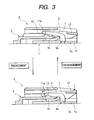
- FIG. 3 shows both connector housings according to the first embodiment in operative states, wherein the upper part of FIG. 3 is a sectional view showing a state where a latch portion is not engaged with an engaging portion, and the lower part of FIG. 3 is a sectional view showing a state where the latch portion is engaged with the engaging portion;
- FIGS. 4A-4C are explanatory views showing modified examples in design of a locking structure according to the first embodiment
- FIG. 5 is a perspective view of a whole lock portion according to the second embodiment
- FIG. 6 is a sectional view showing the lock portion of the female connector housing according to the second embodiment
- FIG. 7 shows both connector housings according to the second embodiment in operative states, wherein the upper part of FIG. 7 is a sectional view showing a state where the latch portion is not engaged with an engaging portion, and the lower part of FIG. 7 is a sectional view showing a state where the latch portion is engaged with the engaging portion;
- FIG. 8 is a sectional view showing a female connector housing according to the third embodiment.
- FIG. 9 shows both connector housings according to the third embodiment in operative states, wherein the upper part of FIG. 9 is a sectional view showing a state where the latch portion is not engaged with an engaging portion, and the lower part of FIG. 9 is a sectional view showing a state where the latch portion is engaged with the engaging portion;
- FIG. 10 is a sectional view showing both connector housings according to the fourth embodiment.
- FIG. 11 is a sectional view showing both the connector housings according to the fourth embodiment in the locked state
- FIG. 12 is a front view of the female connector housing according to the fourth embodiment as seen from a backward end;
- FIG. 13 is a sectional view of the female connector housing according to the fourth embodiment in a state where lever side excessive displacement preventing pieces are abutted against housing side excessive displacement preventing pieces;
- FIG. 14 is a sectional view of the female connector housing according to the fourth embodiment in a state where a latch portion is abutted against an excessive displacement preventing wall portion;
- FIG. 15A is a sectional view showing a lock portion of a conventional locking structure
- FIG. 15B is a view as seen in a direction of an arrow A of FIG. 15A.
- FIG. 15C is a view as seen in a direction of an arrow B of FIG. 15 A.
- FIG. 1 is a perspective view of a whole lock portion in a female connector housing.
- FIG. 2 is a sectional view of a part of the female connector housing taken along an engaging direction of both the male and female connector housings (hereinafter referred to simply as housings).
- FIG. 3 is an explanatory view showing lock arms (arms) in operative state when the two housings are engaged and disengaged.
- FIG. 4 is an explanatory view showing modified examples in design of the locking structure.
- a lock portion 5 in a female housing 1 is provided in a form of an half-divided arrow head by extending its both side walls into the engaging direction (a longitudinal direction in FIG. 1 ), and the side walls constitute a disengaging lever portion 7 .
- a front edge portion 11 laterally extending in a full width.
- Two plate-like lock arms 9 extend backward from the front edge portion 11 substantially horizontally. As shown in FIG. 2, backward end portions (a farmost end in FIG. 1) of the two lock arms 9 are bent downward to form fixed ends 9 a which continue to a horizontal wall portion 1 a of the female housing 1 .
- the front edge portion 11 located between the two lock arms 9 which are laterally spaced constitutes a latch portion 11 a which is adapted to be engaged with an engaging portion 13 of a male housing 3 (See FIG. 3 ).
- An overhanging length of the latch portion 11 a from the fixed ends 9 a of the lock arms is represented by f (See FIG. 2 ).
- Reference numeral 15 in FIG. 2 represents a seal member.
- a lower end portion of the disengaging lever portion 7 is at a substantially same position in the engaging direction as the fixed ends 9 a in the backward part of the lock arms 9 , and constitutes a support portion 7 a which serves as a pivot of rotation of the disengaging lever portion 7 on occasion of lock disengaging operation which will be described later.
- This support portion 7 a has a gap d (See FIG. 2) with respect to the horizontal wall 1 a of the female housing 1 , in a state where the female housing 1 is alone.
- a flat face area extending backward in a full width from the support portion 7 a of the disengaging lever portion 7 constitutes a finger touch portion 17 (lock disengaging operation section) for the lock disengaging operation.
- a distance from the support portion 7 a to the finger touch portion 17 is represented by g, and a distance from the support portion 7 a to the latch portion 11 a is represented by h.
- FIG. 3 shows a state just before the male housing 3 is engaged and locked with the female housing 1 .
- the engaging portion 13 of the male housing 3 comes in contact with the latch portion 11 a of the lock arms 9 , the engaging portion 13 pushes the latch portion 11 a upward.
- the lock arms 9 are subjected to an upward bending moment around the backward fixed ends 9 a . Accordingly, the lock arms 9 are flexed uniformly along their total length f, and the flexure will not be concentrated on the fixed ends 9 a .
- a working radius of the pushing up force is f.
- the radius f is set to be large, a flexural angle of the lock arms 9 near the fixed ends 9 a (hereinafter referred to simply as “the fixed ends 9 a ”) becomes small, thus eliminating a risk of breakage.
- the support portion 7 a of the disengaging lever portion 7 continued from the front edge portion 11 (the latch portion 11 a ) is displaced downward and is brought into contact with the horizontal wall 1 a of the housing.
- the gap d becomes zero.
- the lock arms 9 which have been in a flexed posture since the latch portion 11 a has been pushed up will return to the original posture, allowing the male housing 3 to be locked.
- the gap d of the support portion 7 a will be recovered in the locked state.
- FIG. 3 shows a state in which the lock between the housings 1 and 3 is being disengaged.
- the finger touch portion 17 in the back end of the disengaging lever portion 7 is pushed downward.
- This pushing down operation allows the support portion 7 a of the disengaging lever portion 7 to be lowered and abutted against the horizontal wall 1 a of the female housing 1 .
- an elevating moment acting on the latch portion 11 a is equal to a pushing down moment of the finger touch portion 17 around the support portion 7 a because of a leverage action.
- the elevating force of the latch portion 11 a is smaller than the pushing down force of the finger touch portion 17 , and thus, there will be no fear that the lock arms 9 may be short of strength.
- FIGS. 4A, 4 B and 4 C schematically show modified structures of the support portion 7 a which will serve as the pivot of the rotation of the latch portion 11 a of the lock arms 9 when the lock is disengaged.
- the same reference numerals as the above will be employed in the description.
- FIGS. 4A and 4B show embodiments in which the support portion 7 a is constituted by a projection projected from the horizontal wall 1 a of the housing 1 .
- FIG. 4A there is a gap between the disengaging lever portion 7 and the support portion 7 a during engagement or after disengagement of the lock.
- FIG. 4B shows a case in which the disengaging lever portion 7 and the support portion 7 a are in contact with each other (no gap).
- FIG. 4C shows a structure in which the disengaging lever portion 7 is provided with the support portion 7 a , which is always in contact with the horizontal wall 1 a of the housing 1 .
- the support portion 7 a may be provided on both the horizontal wall 1 a and the disengaging lever portion 7 .
- the disengaging lever portion 7 for disengaging the lock between the male and female housings 3 and 1 by means of the leverage action is provided integrally with the latch portion 11 a of the lock arms 9 in contrast with the prior art. Therefore, occurrence of an excessive stress on the fixed ends 9 a of the lock arms 9 when the latch portion 11 a of the lock arms 9 is flexed by a predetermined amount can be prevented, and thus, a risk of breakage of the lock arms 9 will be eliminated.
- the disengaging lever portion 7 in the first embodiment is connected to the connector housing 1 by way of a thin-walled hinge 18 at an opposite side to the latch portion 11 a interposing the support portion 7 a .
- This hinge 18 projects from the connector housing 1 to be connected to a back end of the lock arms near the support portion 7 a of the disengaging lever portion 7 , and molded integrally with the connector housing 1 .
- the elevating force of the latch portion 11 a is smaller than the pushing down force of the finger touch portion 17 , and thus, there will be no fear that the lock arms 9 may be short of strength.
- This embodiment is an example in which the support portion 7 a is preliminarily in contact with the horizontal wall 1 a of the housing 1 .
- the gap is formed between the support portion 7 a and the horizontal wall 1 a of the housing 1 in the in the initial state, namely before the housings 1 and 3 are engaged, in this embodiment, there is no gap between the support portion 7 a and the horizontal wall 1 a , that is, they are in contact with each other from the beginning.
- a gap is inevitably created between the support portion 7 a and the horizontal wall 1 a due to an extracting direction of metal molds.
- the support portion 7 a and the horizontal wall 1 a can be kept in contact with each other, by applying a load or so after molding.
- the latch portion 11 a is locked with the engaging portion 13 to be brought into a locked condition. Then, by pushing the finger touch portion 17 downward, the locked condition can be disengaged.
- This embodiment is an example in which excessive displacements of the disengaging lever portion 7 in the locking direction and the lock disengaging direction are prevented.
- lever side excessive displacement preventing pieces 20 , 20 are provided on both sides of the finger touch portion 17 in a projecting manner.
- the female connector housing 1 is provided with housing side excessive displacement preventing pieces 21 , 21 (See FIG. 13) opposed to these lever side excessive displacement preventing pieces 20 , 20 on both vertical walls 1 b , 1 b.
- the female connector housing 1 has an outer wall 1 c which covers from the lock arms 9 to the latch portion 11 a .
- An excessive displacement preventing wall portion 22 is provided inside this outer wall 1 c.
- lever side excessive displacement preventing pieces 20 , 20 and the housing side excessive displacement preventing pieces 21 , 21 may be provided on the female connector housing 1 so that the excessive displacements of the disengaging lever portion 7 and the lock arms 9 only in the locking direction may be prevented.
- the above-described fourth embodiment may be combined with the aforesaid second and third embodiments. In such cases, occurrence of the excessive stress on the fixed ends 9 a of the lock arms 9 can be eliminated, and at the same time, the excessive displacements of the disengaging lever portion 7 and the lock arms 9 can be prevented, thus enabling a less breakable lock portion 5 to be formed.
- the member resisting to the displacement of the latch portion when both the housings are engaged is only the arms in a cantilever type, and by appropriately setting the length and thickness of the arms, for example, the arms are uniformly flexed along their full length. Since the stress will not be concentrated on the base end portions of the arms, the flexural angle at the fixed ends of the arms is thus limited to be small, and the arms will become less breakable.
- the latch portion rotates around the pivot together with the disengaging lever portion, whereby the locked condition will be disengaged.
- the pivot of the rotation can be displaced, the latch portion can rotate without resistance, and the arms which have been in the flexed state will not be subjected to an undue load. Therefore, the problem of shortage of strength will not happen.
Landscapes
- Chemical & Material Sciences (AREA)
- General Chemical & Material Sciences (AREA)
- Engineering & Computer Science (AREA)
- Materials Engineering (AREA)
- Health & Medical Sciences (AREA)
- Chemical Kinetics & Catalysis (AREA)
- Medicinal Chemistry (AREA)
- Polymers & Plastics (AREA)
- Organic Chemistry (AREA)
- Details Of Connecting Devices For Male And Female Coupling (AREA)
Applications Claiming Priority (3)
| Application Number | Priority Date | Filing Date | Title |
|---|---|---|---|
| JP2000059288A JP2001250636A (ja) | 2000-03-03 | 2000-03-03 | コネクタのロック構造 |
| JPP.2000-059288 | 2000-03-03 | ||
| JPP.2000-59288 | 2000-03-03 |
Publications (2)
| Publication Number | Publication Date |
|---|---|
| US20010035652A1 US20010035652A1 (en) | 2001-11-01 |
| US6669398B2 true US6669398B2 (en) | 2003-12-30 |
Family
ID=18579767
Family Applications (1)
| Application Number | Title | Priority Date | Filing Date |
|---|---|---|---|
| US09/797,809 Expired - Lifetime US6669398B2 (en) | 2000-03-03 | 2001-03-05 | Locking structure for connector |
Country Status (4)
| Country | Link |
|---|---|
| US (1) | US6669398B2 (de) |
| EP (2) | EP1133019B2 (de) |
| JP (1) | JP2001250636A (de) |
| DE (1) | DE60138848D1 (de) |
Cited By (15)
| Publication number | Priority date | Publication date | Assignee | Title |
|---|---|---|---|---|
| US20060081356A1 (en) * | 2003-07-09 | 2006-04-20 | Sameer Desai | Attachment and articles using same |
| US20060105611A1 (en) * | 2004-11-12 | 2006-05-18 | Sumitomo Wiring Systems, Ltd. | Connector |
| WO2008133893A1 (en) * | 2007-04-27 | 2008-11-06 | Daktronics, Inc. | Transportable electronic sign display system |
| US20100112844A1 (en) * | 2007-01-26 | 2010-05-06 | Huber+Suhner Ag | Connector Comprising a Locking Device |
| US20110076093A1 (en) * | 2009-09-25 | 2011-03-31 | Sumitomo Wiring Systems, Ltd. | Split connector |
| US8016606B1 (en) * | 2011-01-10 | 2011-09-13 | J.S.T. Corporation | Unstressed connector position assurance device and connector assembly |
| US20120156917A1 (en) * | 2010-12-15 | 2012-06-21 | Sumitomo Wiring Systems, Ltd. | Connector |
| US20160156130A1 (en) * | 2014-12-01 | 2016-06-02 | Yazaki Corporation | Connector locking mechanism |
| US20160164224A1 (en) * | 2014-12-08 | 2016-06-09 | Yazaki Corporation | Connector |
| US20160204551A1 (en) * | 2015-01-14 | 2016-07-14 | Yazaki Corporation | Lock structure of connector |
| US20170018874A1 (en) * | 2014-03-31 | 2017-01-19 | Yazaki Corporation | Connector |
| US9948028B2 (en) * | 2016-01-15 | 2018-04-17 | J.S.T. Corporation | Catch structure of latch for connector |
| US10106985B1 (en) * | 2017-12-04 | 2018-10-23 | Better Air Manufacturing Ltd. | Coupling between slab bolster elements |
| US20200076125A1 (en) * | 2018-08-29 | 2020-03-05 | Aptiv Technologies Limited | Connector and connector assembly including the same |
| US10608377B2 (en) | 2018-01-30 | 2020-03-31 | Wago Verwaltungsgesellschaft Mbh | Electrical plug connection |
Families Citing this family (32)
| Publication number | Priority date | Publication date | Assignee | Title |
|---|---|---|---|---|
| US7056142B2 (en) | 2002-04-15 | 2006-06-06 | Yazaki Corporation | Locking structure for connector |
| JP4359414B2 (ja) * | 2002-04-16 | 2009-11-04 | 矢崎総業株式会社 | コネクタのロック構造 |
| JP3963849B2 (ja) * | 2003-02-26 | 2007-08-22 | 矢崎総業株式会社 | コネクタのロック構造 |
| JP4053912B2 (ja) * | 2003-03-19 | 2008-02-27 | ミツミ電機株式会社 | コントロールアダプタ装置 |
| GB2402340B (en) * | 2003-06-06 | 2007-12-12 | Biomet Merck Ltd | Surgical device |
| US7201599B2 (en) * | 2004-03-23 | 2007-04-10 | Fci Americas Technology, Inc. | Electrical connector latch |
| JP4432797B2 (ja) * | 2005-02-23 | 2010-03-17 | 住友電装株式会社 | コネクタ |
| JP4880429B2 (ja) * | 2006-11-20 | 2012-02-22 | 矢崎総業株式会社 | コネクタ |
| DE102006060620B4 (de) * | 2006-12-21 | 2008-10-02 | Tyco Electronics Amp Gmbh | Steckverbinder mit einem Gehäuse mit einem Betätigungselement und einem Rastmittel |
| JP5403806B2 (ja) * | 2009-10-22 | 2014-01-29 | 矢崎総業株式会社 | 電線カバーの装着構造 |
| CN102646895B (zh) * | 2011-02-16 | 2014-08-27 | 富士康(昆山)电脑接插件有限公司 | 连接器 |
| JP5985164B2 (ja) * | 2011-09-07 | 2016-09-06 | 矢崎総業株式会社 | コネクタのロック構造 |
| JP2013077440A (ja) * | 2011-09-30 | 2013-04-25 | Jst Mfg Co Ltd | ロック機構付き電気コネクタ |
| DE102013111506B3 (de) | 2013-10-18 | 2015-01-08 | Phoenix Contact Gmbh & Co. Kg | Steckverbinder mit Verrastungssystem |
| JP6249998B2 (ja) * | 2015-07-06 | 2017-12-20 | 矢崎総業株式会社 | コネクタ |
| JP6602105B2 (ja) | 2015-08-24 | 2019-11-06 | 矢崎総業株式会社 | コネクタ |
| FR3051079B1 (fr) * | 2016-05-03 | 2018-06-15 | Eaxtron | Dispositif de verrouillage pour connecteurs electriques et connecteurs electriques equipes du dispositif. |
| JP6653232B2 (ja) | 2016-09-12 | 2020-02-26 | 矢崎総業株式会社 | コネクタ |
| JP6580548B2 (ja) * | 2016-12-22 | 2019-09-25 | 矢崎総業株式会社 | コネクタ |
| JP6793144B2 (ja) * | 2017-08-04 | 2020-12-02 | 矢崎総業株式会社 | コネクタ |
| JP6844490B2 (ja) * | 2017-10-04 | 2021-03-17 | 住友電装株式会社 | コネクタ |
| JP7137388B2 (ja) * | 2018-07-25 | 2022-09-14 | モレックス エルエルシー | コネクタ |
| JP6786568B2 (ja) * | 2018-10-26 | 2020-11-18 | 矢崎総業株式会社 | 嵌合コネクタ |
| JP6793168B2 (ja) * | 2018-11-09 | 2020-12-02 | 矢崎総業株式会社 | 嵌合コネクタ |
| JP7088873B2 (ja) * | 2019-04-08 | 2022-06-21 | 矢崎総業株式会社 | コネクタ |
| JP2020173987A (ja) * | 2019-04-11 | 2020-10-22 | 矢崎総業株式会社 | コネクタ構造、及び、ロックアームによる係止の解除方法 |
| JP7231480B2 (ja) * | 2019-05-20 | 2023-03-01 | 矢崎総業株式会社 | ハウジング |
| JP7330029B2 (ja) * | 2019-09-17 | 2023-08-21 | 日本端子株式会社 | コネクタ装置 |
| CN115732972A (zh) * | 2021-08-31 | 2023-03-03 | 华为技术有限公司 | 连接器、其制作方法及相关设备 |
| JP7794650B2 (ja) * | 2022-01-31 | 2026-01-06 | 矢崎総業株式会社 | 端子カバー及び端子アッセンブリ |
| JP7436533B2 (ja) * | 2022-02-09 | 2024-02-21 | 矢崎総業株式会社 | ハウジング及びコネクタ |
| JP7776376B2 (ja) * | 2022-04-28 | 2025-11-26 | 矢崎総業株式会社 | コネクタ |
Citations (15)
| Publication number | Priority date | Publication date | Assignee | Title |
|---|---|---|---|---|
| US3602009A (en) * | 1969-09-25 | 1971-08-31 | Stewart Warner Corp | Snap on ferrule |
| US3628812A (en) * | 1969-12-01 | 1971-12-21 | Exxon Production Research Co | Removable pipe connector |
| US3713076A (en) * | 1971-09-30 | 1973-01-23 | Electronic Eng Co | Locking electrical cable connection apparatus |
| US4272145A (en) | 1979-10-22 | 1981-06-09 | Ford Motor Company | Connector lock release |
| US4365696A (en) * | 1980-11-24 | 1982-12-28 | Warn Industries, Inc. | One-piece locking clutch |
| JPS6160482A (ja) * | 1984-08-24 | 1986-03-28 | 松下電器産業株式会社 | 部品供給トレイ |
| US4750238A (en) * | 1985-12-10 | 1988-06-14 | Julius Blum Gesellschaft M.B.H. | Hinge |
| US4801275A (en) | 1987-11-30 | 1989-01-31 | Yazaki Corporation | Connector lock device |
| JPH0254180A (ja) | 1988-07-21 | 1990-02-23 | Opcon Inc | 光電センサの試験方法及び試験装置 |
| US4986766A (en) | 1988-08-17 | 1991-01-22 | Molex Incorporated | Electrical connector having anti-overstress latch |
| JPH0339272A (ja) * | 1989-07-07 | 1991-02-20 | Nec Corp | 通帳自動処理装置 |
| US5104253A (en) * | 1990-06-06 | 1992-04-14 | Chrysler Corporation | Cable assembly, lock therefor |
| US5624272A (en) * | 1994-05-11 | 1997-04-29 | Yazaki Corporation | Connector having locking mechanism |
| US6059598A (en) * | 1997-02-26 | 2000-05-09 | Sumitomo Wiring Systems, Ltd. | Connector |
| US6146183A (en) | 1998-11-10 | 2000-11-14 | Yazaki Corporation | Lock structure |
Family Cites Families (2)
| Publication number | Priority date | Publication date | Assignee | Title |
|---|---|---|---|---|
| JPS6160482U (de) | 1984-09-25 | 1986-04-23 | ||
| DE69836201T2 (de) | 1998-04-24 | 2007-03-08 | Freescale Semiconductor, Inc., Austin | Funkgerät mit Schlaf-Schaltung und -Verfahren |
-
2000
- 2000-03-03 JP JP2000059288A patent/JP2001250636A/ja active Pending
-
2001
- 2001-02-08 EP EP01301102A patent/EP1133019B2/de not_active Expired - Lifetime
- 2001-02-08 DE DE60138848T patent/DE60138848D1/de not_active Expired - Lifetime
- 2001-02-08 EP EP03011162A patent/EP1376774B1/de not_active Expired - Lifetime
- 2001-03-05 US US09/797,809 patent/US6669398B2/en not_active Expired - Lifetime
Patent Citations (15)
| Publication number | Priority date | Publication date | Assignee | Title |
|---|---|---|---|---|
| US3602009A (en) * | 1969-09-25 | 1971-08-31 | Stewart Warner Corp | Snap on ferrule |
| US3628812A (en) * | 1969-12-01 | 1971-12-21 | Exxon Production Research Co | Removable pipe connector |
| US3713076A (en) * | 1971-09-30 | 1973-01-23 | Electronic Eng Co | Locking electrical cable connection apparatus |
| US4272145A (en) | 1979-10-22 | 1981-06-09 | Ford Motor Company | Connector lock release |
| US4365696A (en) * | 1980-11-24 | 1982-12-28 | Warn Industries, Inc. | One-piece locking clutch |
| JPS6160482A (ja) * | 1984-08-24 | 1986-03-28 | 松下電器産業株式会社 | 部品供給トレイ |
| US4750238A (en) * | 1985-12-10 | 1988-06-14 | Julius Blum Gesellschaft M.B.H. | Hinge |
| US4801275A (en) | 1987-11-30 | 1989-01-31 | Yazaki Corporation | Connector lock device |
| JPH0254180A (ja) | 1988-07-21 | 1990-02-23 | Opcon Inc | 光電センサの試験方法及び試験装置 |
| US4986766A (en) | 1988-08-17 | 1991-01-22 | Molex Incorporated | Electrical connector having anti-overstress latch |
| JPH0339272A (ja) * | 1989-07-07 | 1991-02-20 | Nec Corp | 通帳自動処理装置 |
| US5104253A (en) * | 1990-06-06 | 1992-04-14 | Chrysler Corporation | Cable assembly, lock therefor |
| US5624272A (en) * | 1994-05-11 | 1997-04-29 | Yazaki Corporation | Connector having locking mechanism |
| US6059598A (en) * | 1997-02-26 | 2000-05-09 | Sumitomo Wiring Systems, Ltd. | Connector |
| US6146183A (en) | 1998-11-10 | 2000-11-14 | Yazaki Corporation | Lock structure |
Cited By (26)
| Publication number | Priority date | Publication date | Assignee | Title |
|---|---|---|---|---|
| US20060081356A1 (en) * | 2003-07-09 | 2006-04-20 | Sameer Desai | Attachment and articles using same |
| US20060105611A1 (en) * | 2004-11-12 | 2006-05-18 | Sumitomo Wiring Systems, Ltd. | Connector |
| US7101213B2 (en) | 2004-11-12 | 2006-09-05 | Sumitomo Wiring Systems, Ltd. | Connector |
| US20100112844A1 (en) * | 2007-01-26 | 2010-05-06 | Huber+Suhner Ag | Connector Comprising a Locking Device |
| US7887359B2 (en) * | 2007-01-26 | 2011-02-15 | Rosenberger Hochfrequenztechnik Gmbh & Co. Kg | Connector comprising a locking device |
| WO2008133893A1 (en) * | 2007-04-27 | 2008-11-06 | Daktronics, Inc. | Transportable electronic sign display system |
| US8827737B2 (en) * | 2009-09-25 | 2014-09-09 | Sumitomo Wiring Systems, Ltd. | Split connector |
| US20110076093A1 (en) * | 2009-09-25 | 2011-03-31 | Sumitomo Wiring Systems, Ltd. | Split connector |
| CN102570133B (zh) * | 2010-12-15 | 2015-11-25 | 住友电装株式会社 | 连接器 |
| US20120156917A1 (en) * | 2010-12-15 | 2012-06-21 | Sumitomo Wiring Systems, Ltd. | Connector |
| US8882528B2 (en) * | 2010-12-15 | 2014-11-11 | Sumitomo Wiring Systems, Ltd. | Connector |
| CN102570133A (zh) * | 2010-12-15 | 2012-07-11 | 住友电装株式会社 | 连接器 |
| US8016606B1 (en) * | 2011-01-10 | 2011-09-13 | J.S.T. Corporation | Unstressed connector position assurance device and connector assembly |
| US20170018874A1 (en) * | 2014-03-31 | 2017-01-19 | Yazaki Corporation | Connector |
| US10263363B2 (en) * | 2014-03-31 | 2019-04-16 | Yazaki Corporation | Connector |
| US20160156130A1 (en) * | 2014-12-01 | 2016-06-02 | Yazaki Corporation | Connector locking mechanism |
| US9583876B2 (en) * | 2014-12-01 | 2017-02-28 | Yazaki Corporation | Connector locking mechanism |
| US9425549B2 (en) * | 2014-12-08 | 2016-08-23 | Yazaki Corporation | Connector |
| US20160164224A1 (en) * | 2014-12-08 | 2016-06-09 | Yazaki Corporation | Connector |
| US20160204551A1 (en) * | 2015-01-14 | 2016-07-14 | Yazaki Corporation | Lock structure of connector |
| US9780489B2 (en) * | 2015-01-14 | 2017-10-03 | Yazaki Corporation | Lock structure of connector |
| US9948028B2 (en) * | 2016-01-15 | 2018-04-17 | J.S.T. Corporation | Catch structure of latch for connector |
| US10106985B1 (en) * | 2017-12-04 | 2018-10-23 | Better Air Manufacturing Ltd. | Coupling between slab bolster elements |
| US10608377B2 (en) | 2018-01-30 | 2020-03-31 | Wago Verwaltungsgesellschaft Mbh | Electrical plug connection |
| US20200076125A1 (en) * | 2018-08-29 | 2020-03-05 | Aptiv Technologies Limited | Connector and connector assembly including the same |
| US10868391B2 (en) * | 2018-08-29 | 2020-12-15 | Aptiv Technologies Limited | Connector and connector assembly including the same |
Also Published As
| Publication number | Publication date |
|---|---|
| EP1133019B2 (de) | 2012-10-17 |
| EP1133019B1 (de) | 2009-06-03 |
| EP1133019A3 (de) | 2002-11-06 |
| JP2001250636A (ja) | 2001-09-14 |
| EP1376774B1 (de) | 2007-05-02 |
| US20010035652A1 (en) | 2001-11-01 |
| EP1376774A3 (de) | 2004-11-17 |
| DE60138848D1 (de) | 2009-07-16 |
| EP1133019A2 (de) | 2001-09-12 |
| EP1376774A2 (de) | 2004-01-02 |
Similar Documents
| Publication | Publication Date | Title |
|---|---|---|
| US6669398B2 (en) | Locking structure for connector | |
| US6354860B1 (en) | Connector and connector assembly | |
| US6902420B2 (en) | Connector lock structure | |
| US5709560A (en) | Connector having a pivotable connection-assistance member | |
| US8882528B2 (en) | Connector | |
| JP2004319155A (ja) | コネクタ | |
| EP1657790B1 (de) | Verbinder | |
| JP2001076811A (ja) | レバー式コネクタ | |
| US20030148647A1 (en) | Lock release mechanism using pull-tab and connector having the lock release mechanism | |
| US5203715A (en) | Connector | |
| JPH07220807A (ja) | ロック付きコネクタハウジング | |
| JP2001160457A (ja) | 半嵌合防止コネクタ | |
| EP0774802B1 (de) | Elektrischer Verbinder mit internem elastischen Teil | |
| JP3912253B2 (ja) | コネクタ | |
| JP7742495B2 (ja) | ロックシステムを有するプラグコネクタ | |
| CN106663891A (zh) | 接触元件 | |
| JP5636938B2 (ja) | コネクタ | |
| JPH09324805A (ja) | 樹脂成形品のロック装置 | |
| JP2003123890A (ja) | コネクタ | |
| US7104829B2 (en) | Connector with locking arm having a window | |
| JP4052642B2 (ja) | コネクタ | |
| GB2599908A (en) | Electrical connector with a connector position assurance member | |
| JP6314068B2 (ja) | コネクタハウジング | |
| JP2967881B2 (ja) | コンタクト | |
| JP2003346964A (ja) | コネクタ |
Legal Events
| Date | Code | Title | Description |
|---|---|---|---|
| AS | Assignment |
Owner name: YAZAKI CORPORATION, JAPAN Free format text: ASSIGNMENT OF ASSIGNORS INTEREST;ASSIGNORS:WADA, YOSHIMI;OHTAKA, KAZUTO;TANAKA, SHIGERU;AND OTHERS;REEL/FRAME:011586/0343;SIGNING DATES FROM 20010127 TO 20010129 |
|
| FEPP | Fee payment procedure |
Free format text: PAYOR NUMBER ASSIGNED (ORIGINAL EVENT CODE: ASPN); ENTITY STATUS OF PATENT OWNER: LARGE ENTITY |
|
| STCF | Information on status: patent grant |
Free format text: PATENTED CASE |
|
| FPAY | Fee payment |
Year of fee payment: 4 |
|
| FPAY | Fee payment |
Year of fee payment: 8 |
|
| FPAY | Fee payment |
Year of fee payment: 12 |