US5952729A - Wiring structure in motorcycle - Google Patents
Wiring structure in motorcycle Download PDFInfo
- Publication number
- US5952729A US5952729A US08/974,504 US97450497A US5952729A US 5952729 A US5952729 A US 5952729A US 97450497 A US97450497 A US 97450497A US 5952729 A US5952729 A US 5952729A
- Authority
- US
- United States
- Prior art keywords
- handlebar cover
- bus bar
- switch
- motorcycle
- embedded
- Prior art date
- Legal status (The legal status is an assumption and is not a legal conclusion. Google has not performed a legal analysis and makes no representation as to the accuracy of the status listed.)
- Expired - Fee Related
Links
Images


Classifications
-
- B—PERFORMING OPERATIONS; TRANSPORTING
- B60—VEHICLES IN GENERAL
- B60R—VEHICLES, VEHICLE FITTINGS, OR VEHICLE PARTS, NOT OTHERWISE PROVIDED FOR
- B60R16/00—Electric or fluid circuits specially adapted for vehicles and not otherwise provided for; Arrangement of elements of electric or fluid circuits specially adapted for vehicles and not otherwise provided for
- B60R16/005—Electro-mechanical devices, e.g. switched
-
- B—PERFORMING OPERATIONS; TRANSPORTING
- B60—VEHICLES IN GENERAL
- B60R—VEHICLES, VEHICLE FITTINGS, OR VEHICLE PARTS, NOT OTHERWISE PROVIDED FOR
- B60R16/00—Electric or fluid circuits specially adapted for vehicles and not otherwise provided for; Arrangement of elements of electric or fluid circuits specially adapted for vehicles and not otherwise provided for
- B60R16/02—Electric or fluid circuits specially adapted for vehicles and not otherwise provided for; Arrangement of elements of electric or fluid circuits specially adapted for vehicles and not otherwise provided for electric constitutive elements
- B60R16/0207—Wire harnesses
-
- B—PERFORMING OPERATIONS; TRANSPORTING
- B62—LAND VEHICLES FOR TRAVELLING OTHERWISE THAN ON RAILS
- B62J—CYCLE SADDLES OR SEATS; AUXILIARY DEVICES OR ACCESSORIES SPECIALLY ADAPTED TO CYCLES AND NOT OTHERWISE PROVIDED FOR, e.g. ARTICLE CARRIERS OR CYCLE PROTECTORS
- B62J11/00—Supporting arrangements specially adapted for fastening specific devices to cycles, e.g. supports for attaching maps
- B62J11/10—Supporting arrangements specially adapted for fastening specific devices to cycles, e.g. supports for attaching maps for mechanical cables, hoses, pipes or electric wires, e.g. cable guides
- B62J11/19—Supporting arrangements specially adapted for fastening specific devices to cycles, e.g. supports for attaching maps for mechanical cables, hoses, pipes or electric wires, e.g. cable guides specially adapted for electric wires
-
- B—PERFORMING OPERATIONS; TRANSPORTING
- B62—LAND VEHICLES FOR TRAVELLING OTHERWISE THAN ON RAILS
- B62J—CYCLE SADDLES OR SEATS; AUXILIARY DEVICES OR ACCESSORIES SPECIALLY ADAPTED TO CYCLES AND NOT OTHERWISE PROVIDED FOR, e.g. ARTICLE CARRIERS OR CYCLE PROTECTORS
- B62J50/00—Arrangements specially adapted for use on cycles not provided for in main groups B62J1/00 - B62J45/00
- B62J50/20—Information-providing devices
- B62J50/21—Information-providing devices intended to provide information to rider or passenger
- B62J50/22—Information-providing devices intended to provide information to rider or passenger electronic, e.g. displays
-
- B—PERFORMING OPERATIONS; TRANSPORTING
- B62—LAND VEHICLES FOR TRAVELLING OTHERWISE THAN ON RAILS
- B62K—CYCLES; CYCLE FRAMES; CYCLE STEERING DEVICES; RIDER-OPERATED TERMINAL CONTROLS SPECIALLY ADAPTED FOR CYCLES; CYCLE AXLE SUSPENSIONS; CYCLE SIDE-CARS, FORECARS, OR THE LIKE
- B62K11/00—Motorcycles, engine-assisted cycles or motor scooters with one or two wheels
- B62K11/14—Handlebar constructions, or arrangements of controls thereon, specially adapted thereto
Definitions
- the present invention relates to a wiring structure in a motorcycle, which is designed so that an electric current is supplied through a conductor to an electric part supported in a handlebar cover for covering a handlebar in the motorcycle.
- Such a wiring structure in the motorcycle is known, for example, from Japanese Patent Application Laid-open No.60-244680.
- a switch is mounted in the handlebar cover for covering the handlebar of the motorcycle and wired to another electric part by use of a wire harness.
- the above known structure suffers from a problem that the number of parts is increased for performing the wiring using the wire harness, but also the number of working steps is increased because of a troublesome operation for attaching and detaching connectors at opposite ends of the wire harness during assembling.
- a wiring structure in a motorcycle for supplying an electric current through a conductor to an electric part supported in a handlebar cover for covering a handlebar in the motorcycle, wherein the conductor is formed of a bus bar made of a metal plate or a metal bar embedded in the handlebar cover.
- a meter unit is disposed at a substantially central portion of the handlebar cover, and the bus bar connected to the electric part is connected to a junction box which is mounted on a mounting portion of the meter unit and to which a connector of a wire harness is connected.
- a plurality of bus bars can be disposed radiately about the junction box to avoid the interference with one another, and the entire length of such bus bars can be suppressed to the minimum.
- a wiring structure in a motorcycle for supplying an electric current through a conductor to an electric part supported in a handlebar cover for covering a handlebar in the motorcycle, wherein a bus bar-embedded substrate is mounted within the handlebar cover, and the conductor is formed of a bus bar made of a metal plate or a metal bar-embedded in the bus bar-embedded substrate.
- a wiring structure in a motorcycle for supplying an electric current through a conductor to an electric part supported in a handlebar cover for covering a handlebar in the motorcycle, wherein a meter unit, to which a connector of a wire harness is connected, is mounted at a substantially central portion of the handlebar cover, and a bus bar-embedded substrate having a base of a synthetic resin and bus bar made of a metal plate or a metal bar embedded within the base, the bus bar-embedded substrate being connected at one of opposite ends thereof to the meter unit and fixed at the other end thereof to an inner surface of the handlebar cover, the electric part being fixed to the bus bar-embedded substrate by inserting the electric part into an opening defined in the handlebar cover.
- the bus bar-embedded substrate which has the bus bar made of a metal plate or metal bar embedded within the base of synthetic resin in place of the conventional wire harness. Therefore, it is possible to decrease the possibility of occurrence of a short-circuiting, a breaking of a wire, a mis-assembling and the like, but also to enhance the durability of the bus bar used for a long period, as compared with the wire harness. Moreover, a plurality of bus bars can be disposed radiately of the bus bar-embedded substrate from the meter unit mounted at the substantially central portion of the handlebar cover to avoid the interference with one another, and the entire length of the bus bars can be suppressed to the minimum.
- bus bars are to be embedded in the bus bar-embedded substrate mounted within the handlebar cover, it is easy to produce the handlebar cover, leading to a reduced cost. Further, the fixing and connection of the electric part are simultaneously completed, only by inserting the electric part through an opening in the handlebar cover, after the handlebar cover having the bus bar-embedded substrate previously mounted therein is fixed to a vehicle body. This leads to an enhanced assembling workability and a decreased number of assembling steps.
- FIGS. 1 to 7 illustrate a first embodiment of the present invention, wherein
- FIG. 1 is an exploded perspective view taken from the front of a rear handlebar cover in a motorcycle
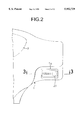
- FIG. 2 is an enlarged view taken in the direction of an arrow 2 in FIG. 1;
- FIG. 3 is a sectional view taken along a line 3--3 in FIG. 2;
- FIG. 4 is a sectional view taken along a line 4--4 in FIG. 3;
- FIG. 5 is a sectional view taken along a line 5--5 in FIG. 4;
- FIG. 6 is an exploded perspective view of a starter switch
- FIG. 7 is a diagram for explaining a wiring provided by bus bars
- FIG. 8 is an exploded perspective view taken from the front of a rear handlebar cover in a motorcycle according to a second embodiment of the present invention.
- FIGS. 9 to 12 illustrate a third embodiment of the present invention, wherein
- FIG. 9 is an exploded perspective view taken from the front of a rear handlebar cover in a motorcycle.
- FIG. 10 is a view similar to FIG. 3;
- FIG. 11 is a sectional view taken along a line 11--11 in FIG. 10.
- FIG. 12 is a sectional view taken along a line 12--12 in FIG. 11.
- reference character 1 is a rear handlebar cover made of a synthetic resin for covering a rear portion of a handlebar of a motorcycle.
- the handlebar cover 1 has a notch 1 1 which is defined at a right end thereof as viewed from a rider and through which a right half of the handlebar is passed, a notch 1 2 which is defined at a left end thereof and through which a left half of the handlebar 1 is passed, and a notch 1 3 which is a lower end thereof and through which a steering shaft is passed.
- a junction box 2 is integrally formed at a central portion of the rear handlebar cover 1 to protrude a forwards of a vehicle body, and a meter unit 3 is mounted to the junction box 2 from the rearward of the vehicle body.
- the meter unit 3 is comprised of a meter body 4 including a print board having electronic parts such as IC and a liquid crystal display mounted therein, a meter indicating plate 5 and a mater lens 6.
- a pair of left and right turn-signal bulbs 7, 7 and a pair of left and right illuminating bulbs 8, 8 are mounted in the meter body 4.
- Three connectors 9, 10 and 11 are mounted in a front surface of the junction box 2.
- a connector 13 of a main harness 12 connected to a battery or a starter motor mounted on the vehicle body is coupled to the connector 9.
- a connector 15 of a front handlebar cover harness 14 connected to a head light or winker lamp in a front handlebar cover mounted to the front surface of the rear handlebar cover 1 is coupled to the connector 10.
- a winker relay 16 is coupled to the connector 11.
- a starter switch Ss is mounted in an opening 1 4 defined in a right portion of the rear handlebar cover 1.
- a first bus bar-embedding substrate 17 is projecting provided in a band-like shape on an inner surface of the rear handlebar cover 1 to connect the opening 14 in the starter switch S s and the junction box 2 to each other.
- Three openings 1 5 , 1 6 and 1 7 for mounting of a dimmer switch Sd, a winker switch Sw and a horn switch Sh are defined in a left portion of the rear handlebar cover 1.
- a second bus bar embedding substrate 18 is projecting provided on the inner surface of the rear handlebar cover 1 to surround the three openings 1 5 , 1 6 and 1 7 .
- a third bus bar embedding substrate 19 is projecting provided on the inner surface of the rear handlebar cover 1 to connect the second bus bar embedding substrate 18 and the junction box 2.
- a plurality of bus bars which will be described hereinafter are embedded in each of the bus bar embedding substrates 17, 18 and 19.
- the starter switch Ss, the dimmer switch Sd, the winker switch Sw and the horn switch Sh are connected to the inside of the junction box 2 through these bus bars.
- the starter switch Ss includes a switch housing 21 which opens at its upper and front surfaces.
- a contact holder 22 is fitted in an opening in the upper surface of the switch housing 21 and fixed by bringing projections 22 1 , 22 1 provided on a side of the contact holder 22 into engagement in locking bores 21 1 , 21 1 , in the switch housing 21.
- a switch lever 23 is fitted into an opening in the front surface of the switch housing 21 and swingably supported by bringing a pair of upper and lower pins 23 1 , 23 1 projecting provided at one end of the switch lever 23 into engagement with the switch housing 21 and the contact holder 23, so that the switch lever 23 can be swung about the pins 23 1 , 23 1 .
- a pair of stationary contacts 24 and 25 made by bending a metal plate are fitted into a pair of contact support portions 22 2 and 22 3 formed in the contact holder 22.
- a portion of a lower surface of each of the stationary contacts 24 and 25 is covered with each of plate-like insulators 26, 26, with contact portions 24 1 and 25 1 of the stationary contacts 24 and 25 being exposed in turned-down states at locations adjoining the insulators 26, 26.
- a movable contact 28 biased upwards by a spring 27 is vertically slidably carried on an upper surface of the switch lever 23. The movable contact 28 is slidable over the insulators 26, 26 and the contact portions 24 1 and 25 1 .
- a pin 30 biased forwards by a spring 29 protrudes for advancing and retreating movements from a back of the switch lever 23, so that a tip end of the pin 30 resiliently abuts against the inner surface of the switch housing 21.
- the resilient force of the spring 29 acts to push back the other end of the switch lever 23.
- bus bars 31 and 32 made of a band-like metal plate are embedded in the first bus bar embedding substrate 17 (see FIG. 1).
- the bus bars 31 and 32 are incorporated in the rear handlebar cover 1 when the rear handlebar cover 1 is produced by an injection molding.
- Terminals 31 1 and 32 1 formed at one ends of the bus bars 31 and 32 are exposed in the vicinity of the opening 1 4 in the rear handlebar cover 1.
- Terminals 24 2 and 25 2 having a resilience and formed by folding the stationary contacts 24 and 25 of the starter switch Ss abut against the terminals 31 1 and 32 1 .
- Each of the dimmer switch Sd, the winker switch Sw and the horn switch Sh also is mounted to the rear handlebar cover 1 in a structure similar to that of the starter switch Ss.
- a plurality of bus bars for connecting each of the dimmer switch Sd, the winker switch Sw and the horn switch Sh to the junction box 2 are also embedded in each of the second and third bus bar embedding substrates 18 and 19. More specifically, as can be seen from FIG.
- the wiring to the electric parts including the starter switch Ss, the dimmer switch Sd, the winker switch Sw and the horn switch Sh mounted to the rear handlebar cover 1 of the motorcycle is performed by the bus bars 31 to 40 embedded in the rear handlebar cover 1. Therefore, as compared with the case where the conventional wire harnesses are used, it is possible not only to substantially reduce the numbers of parts and steps required for the wiring, but also to decrease the possibility of occurrence of a short-circuiting, breaking, mis-assembling and the like. Moreover, it is possible to enhance the durability of the bus bars used for a long period, as compared with the wire harnesses.
- junction box 2 is mounted on the mounting portion for the meter unit 3 located at the central section of the rear handlebar cover 1, and the bus bars 31 to 40 are disposed radiately about the junction box 2, it is possible to suppress the entire length of the bus bars 31 to 40 to the minimum, while avoiding the mutual interference of the bus bars 31 to 40.
- FIG. 8 A second embodiment of the present invention will now be described with reference to FIG. 8.
- the same reference characters as those in the first embodiment are affixed to members, portions or components corresponding to those in the first embodiment.
- the second embodiment includes a bus bar embedding substrate 41 made of a synthetic resin and locked and fixed with its four locking recesses 415 locked in four locking claws 1 9 projecting provided on an inner surface of a rear handlebar cover 1.
- bus bars 31 to 40 are integrally embedded in the bus bar embedding substrate 41.
- the bus bar embedding substrate 41 includes four openings 41 1 , 41 2 , 41 3 and 41 4 corresponding to the four openings 1 4 , 1 5 , 1 6 and 1 7 in the rear handlebar cover 1.
- the starter switch Ss, the dimmer switch Sd, the winker switch Sw and the horn switch Sh are passed through the openings 1 4 , 1 5 , 1 6 and 1 7 in the rear handlebar cover 1 and locked in the openings 41 1 , 41 2 , 41 3 and 41 4 in the bus bar embedding substrate 41, where the switches Ss, Sd, Sw and Sh are connected by the bus bars 31 to 40 in a structure similar to that in the first embodiment.
- the meter unit 3 fitted in the opening 1 8 defined at the center of the rear handlebar cover 1 and fixed by two locking claws 1 10 , 1 10 is coupled to the bus bar embedding substrate 41 through a connector 42 mounted on a back of the meter unit 3.
- the connector 13 of the main harness 12, the connector 15 of the front handlebar cover 14 and the winker relay 16 are coupled to three connectors 9, 10 and 11 provided on the bus bar embedding substrate 41.
- the second embodiment can provide an operational effect which will be described below. Since the bus bars 31 to 40 are embedded in the bus bar embedding substrate 41 mounted to the rear handlebar cover 1, rather than being embedded directly in the rear handlebar cover 1, it is possible to simplify the structure of a die for producing the rear handlebar cover 1 by an injection molding to reduce the cost.
- a meter unit 3 fitted into an opening 1 8 defined at the central portion of the rear handlebar cover 1 is fixed by three locking claws 1 13 provided around the opening 1 8 .
- Three connectors 9, 10 and 11 are mounted on the front surface of the meter unit 3.
- a connector 13 of a main harness 12 connected to a battery or a starter motor mounted on a vehicle body is coupled to the connector 9.
- a connector 15 of a front handlebar cover harness 14 connected to a headlight or winker lamp in the front handlebar cover counted on the front surface of the rear handlebar cover 1 is connected to the connector 10, and a winker relay 16 is coupled to the connector 11.
- the starter switch Ss is fitted in an opening 1 4 defined in a right portion of the handlebar cover 1, and the starter switch Ss and the meter unit 3 are interconnected by a first bus bar embedding substrate 17.
- Three openings 1 5 , 1 6 and 1 7 are defined in a left portion of the rear handlebar cover 1, and the dimmer switch Sd, the winker switch Sw and the horn switch Sh are fitted in the openings 1 5 , 1 6 and 1 7 .
- the three switches Sd, Sw and Sh and the meter unit 3 are connected together by a second bus bar embedding substrate 18.
- the structure of the starter switch Ss is substantially the same as that in the first embodiment.
- the structure of the first bus bar embedding substrate 17 will be described below with reference to FIGS. 10 to 12.
- the first bus bar embedding substrate 17 is provided with a bus bar embedding portion 51 having a flexibility and formed into a thin plate-like shape from a synthetic resin.
- Two bus bars 31 and 32 made of a band-like metal plate are embedded in the bus bar embedding portion 51.
- the bus bars 31 and 32 are incorporated in the first bus bar embedding substrate 17.
- a connector 52 integrally formed at one end of the bus bar embedding portion 51 is fitted into an opening 3 5 defined in the meter unit 3 and locked therein by a locking claw 3 6 (see FIG. 9).
- An opening 53 1 is provided through the switch support portion 53 of the first bus bar embedding substrate 17, and the starter switch Ss is fitted into the opening 53 1 . Terminals 31 1 and 32 1 formed at one ends of bus bars 31 and 32 embedded in the bus bar embedding portion 51 are exposed to the opening 53 1 .
- the starter switch Ss is inserted into the opening 53 1 in the switch support portion 53 of the first bus bar embedding substrate 17, two locking claws 21 2 , 21 2 formed on the switch housing 21 are brought into engagement with the edge of the opening 53 1 to fix the starter switch Ss to the first bus bar embedding substrate 17.
- the terminals 24 2 and 25 2 having the resilience and formed by folding the stationary contacts 24 and 25 of the starter switch Ss abut against the terminals 31 1 and 32 1 of the bus bars 31 and 32, whereby the connection of the starter switch Ss and the bus bars 31 and 32 is automatically completed and moreover, a reliable electric conduction is ensured by the resilience of the terminals 24 2 and 25 2 .
- means such as a bolt, a connector, a soldering and the like is not used for fixing and wiring of the starter switch Ss, it is possible to reduce the number of parts and the number of assembling steps.
- the second bus bar embedding substrate 18 connecting the dimmer switch Sd, the winker switch Sw and the horn switch Sh to the meter unit 3 also has the substantially same structure as that of the first bus bar embedding substrate 17.
- the second bus bar embedding substrate 18 includes a bus bar embedding portion 54 having a plurality of bus bars embedded therein, a connector 55 connected to the meter unit 3, and a switch support portion 56 fixed to the rear handlebar cover 1 to support the dimmer switch Sd, the winker switch Sw and the horn switch Sh (see FIG. 9).
- the connector 55 is fitted into an opening 3 7 in the meter unit 3 and locked by locking claws 3 8 , 3 8 , and the switch support portion 56 is locked by locking claws 1 10 , 1 10 ; 1 11 , 1 11 and 1 12 , 1 12 provided on the rear handlebar cover 1.
- the first and second embedding substrates 17 and 18 for performing the wiring for the electric parts including the starter switch Ss, the dimmer switch Sd, the winker switch Sw and the horn switch Sh mounted to the rear handlebar cover 1 of the motorcycle are stable in form and cannot be entangle and wound, as is the wire harness and moreover, have a moderate softness. Therefore, it is easy to mount and detach the first and second embedding substrates 17 and 18, and the first and second embedding substrates 17 and 18 are excellent in assemblability.
- first and second bus bar embedding substrates 17 and 18 are disposed radiately about the meter unit 3 located at the central portion of the rear handlebar cover 1, it is possible to suppress the entire length of the bus bars 31 to 41 to the minimum, while avoiding the mutual interference of the first and second bus bar embedding substrates 17 and 18.
- bus bars 31 to 40 are embedded in the first and second embedding substrates 17 and 18 capable of being attached to and detached from the rear handlebar cover 1, rather than being embedded directly on the rear handlebar cover 1, it is possible to simplify the structure of a mold for producing the rear handlebar cover 1 by injection molding to reduce the cost.
- each of the bus bars 31 to 40 has been formed from the band-like metal plate in the embodiments, but may be formed into any sectional shape from a metal rod having a circular or polygonal section.
- the starter switch Ss, the dimmer switch Sd, the winker switch Sw and the horn switch Sh have been illustrated as the electric parts in the embodiments, but according to the present invention, any other electric parts may be utilized.
- the bus bars 31 to 40 have been embedded in the rear handlebar cover 1 in the first embodiment, but may be embedded in any portion of the handlebar cover.
Landscapes
- Engineering & Computer Science (AREA)
- Mechanical Engineering (AREA)
- Lighting Device Outwards From Vehicle And Optical Signal (AREA)
- Switch Cases, Indication, And Locking (AREA)
- Lock And Its Accessories (AREA)
- Motorcycle And Bicycle Frame (AREA)
- Insulated Conductors (AREA)
Priority Applications (14)
| Application Number | Priority Date | Filing Date | Title |
|---|---|---|---|
| JP14534596A JP3515663B2 (ja) | 1996-06-07 | 1996-06-07 | 自動二輪車の配線構造 |
| JP14534396A JP3793282B2 (ja) | 1996-06-07 | 1996-06-07 | 自動二輪車の配線構造 |
| IDP971877A ID17166A (id) | 1996-06-07 | 1997-06-03 | Struktur pemasangan sakelar |
| IDP971876A ID17731A (id) | 1996-06-07 | 1997-06-03 | Struktur kabel pada sepeda motor |
| DE69710519T DE69710519T2 (de) | 1996-06-07 | 1997-06-05 | Verkabelungsstruktur |
| EP97303862A EP0811527B1 (en) | 1996-06-07 | 1997-06-05 | Switch mounting structure |
| EP97303863A EP0811530B1 (en) | 1996-06-07 | 1997-06-05 | Wiring structure in motorcycle |
| ES97303863T ES2173386T3 (es) | 1996-06-07 | 1997-06-05 | Estructura de cableado para moticicletas. |
| ES97303862T ES2198534T3 (es) | 1996-06-07 | 1997-06-05 | Dispositivo de montaje de un interruptor. |
| DE69721633T DE69721633T2 (de) | 1996-06-07 | 1997-06-05 | Montagestruktur eines Schalters |
| CN97105460A CN1071477C (zh) | 1996-06-07 | 1997-06-06 | 开关安装结构 |
| CN97105459A CN1071216C (zh) | 1996-06-07 | 1997-06-06 | 摩托车内布线结构 |
| US08/974,504 US5952729A (en) | 1996-06-07 | 1997-11-19 | Wiring structure in motorcycle |
| US08/975,106 US6344621B1 (en) | 1996-06-07 | 1997-11-20 | Switch mounting structure |
Applications Claiming Priority (4)
| Application Number | Priority Date | Filing Date | Title |
|---|---|---|---|
| JP14534596A JP3515663B2 (ja) | 1996-06-07 | 1996-06-07 | 自動二輪車の配線構造 |
| JP14534396A JP3793282B2 (ja) | 1996-06-07 | 1996-06-07 | 自動二輪車の配線構造 |
| US08/974,504 US5952729A (en) | 1996-06-07 | 1997-11-19 | Wiring structure in motorcycle |
| US08/975,106 US6344621B1 (en) | 1996-06-07 | 1997-11-20 | Switch mounting structure |
Publications (1)
| Publication Number | Publication Date |
|---|---|
| US5952729A true US5952729A (en) | 1999-09-14 |
Family
ID=27472621
Family Applications (1)
| Application Number | Title | Priority Date | Filing Date |
|---|---|---|---|
| US08/974,504 Expired - Fee Related US5952729A (en) | 1996-06-07 | 1997-11-19 | Wiring structure in motorcycle |
Country Status (6)
| Country | Link |
|---|---|
| US (1) | US5952729A (zh) |
| EP (1) | EP0811530B1 (zh) |
| CN (1) | CN1071216C (zh) |
| DE (1) | DE69710519T2 (zh) |
| ES (1) | ES2173386T3 (zh) |
| ID (1) | ID17731A (zh) |
Cited By (10)
| Publication number | Priority date | Publication date | Assignee | Title |
|---|---|---|---|---|
| US6319013B2 (en) * | 1997-12-01 | 2001-11-20 | Toyo Denso Co., Ltd. | Wiring structure for motorcycle with busbars |
| US6581709B2 (en) * | 2000-05-30 | 2003-06-24 | Misturu Tsuji | Small article compartment device for saddle type vehicle |
| US20050028635A1 (en) * | 2001-11-12 | 2005-02-10 | Yoshimichi Onoda | Steering column module |
| US20050051374A1 (en) * | 2003-09-09 | 2005-03-10 | Honda Motor Co., Ltd. | Rear fender and related support structure for a motorcycle, and motorcycle including same |
| US20070148993A1 (en) * | 2005-12-28 | 2007-06-28 | Yazaki Corporation | Electric connection box |
| US20090109647A1 (en) * | 2007-10-24 | 2009-04-30 | Toyota Motor Engineering & Manufacturing North America, Inc. | Switch Mount |
| US7850556B2 (en) | 2001-07-11 | 2010-12-14 | Campagnolo S.R.L. | Intermediate connection unit usable on board of a bicycle |
| US20110017560A1 (en) * | 2009-07-23 | 2011-01-27 | Harley-Davidson Motor Company Group, LLC | Master cylinder-mounted display for a motorcycle |
| US20170001674A1 (en) * | 2013-12-06 | 2017-01-05 | Kawasaki Jukogyo Kabushiki Kaisha | Motorcycle |
| USD920200S1 (en) * | 2019-09-24 | 2021-05-25 | Gogoro Inc. | Scooter |
Families Citing this family (3)
| Publication number | Priority date | Publication date | Assignee | Title |
|---|---|---|---|---|
| JP4442652B2 (ja) * | 2007-07-05 | 2010-03-31 | 住友電装株式会社 | 車載用電気接続箱 |
| CN105644469B (zh) * | 2016-03-25 | 2018-04-06 | 天津飞踏自行车有限公司 | 一种多线束防水连接装置 |
| US11897573B2 (en) * | 2020-08-26 | 2024-02-13 | Shimano Inc. | Operating device for human-powered vehicle |
Citations (8)
| Publication number | Priority date | Publication date | Assignee | Title |
|---|---|---|---|---|
| US4229662A (en) * | 1977-10-13 | 1980-10-21 | Honda Giken Kogyo Kabushiki Kaisha | Wiring of electrical equipments for motorcycles |
| US4386278A (en) * | 1980-05-26 | 1983-05-31 | Honda Giken Kogyo Kabushiki Kaisha | Wiring harness for motorcycles |
| US4471209A (en) * | 1981-12-31 | 1984-09-11 | Hollander James M | Electrically heated hand grips for vehicle handle bars |
| JPS60244680A (ja) * | 1984-05-19 | 1985-12-04 | 本田技研工業株式会社 | 車両におけるスイツチ取付構造 |
| US5255155A (en) * | 1990-09-19 | 1993-10-19 | Sumitomo Wiring Systems, Ltd. | Structure of electric circuit panel for instrument panel of automobile and method for forming the same |
| US5627409A (en) * | 1994-03-28 | 1997-05-06 | Yazaki Corporation | Meter module assembly |
| US5808373A (en) * | 1996-03-11 | 1998-09-15 | Harness System Technologies Research | Vehicle glove box adapted to receive and power electrical equipment |
| US5889337A (en) * | 1996-04-23 | 1999-03-30 | Sumitomo Wiring Systems, Ltd. | Integrated instrument panel switch assembly |
Family Cites Families (4)
| Publication number | Priority date | Publication date | Assignee | Title |
|---|---|---|---|---|
| EP0130844B2 (en) * | 1983-07-05 | 1997-09-03 | Sumitomo Wiring Systems, Ltd. | Interconnection apparatus for wiring harnesses |
| CN2078925U (zh) * | 1990-12-19 | 1991-06-12 | 魏俊生 | 一种汽车组合开关 |
| IT233433Y1 (it) * | 1994-05-18 | 2000-01-28 | Pagani Spa | Sistema di fissaggio antisfilamento di un circuito flessibile a scatole portamovimenti per la realizzazione delle connessioni |
| US5497036A (en) * | 1994-10-21 | 1996-03-05 | Harley-Davidson | Motorcycle terminal box assembly |
-
1997
- 1997-06-03 ID IDP971876A patent/ID17731A/id unknown
- 1997-06-05 ES ES97303863T patent/ES2173386T3/es not_active Expired - Lifetime
- 1997-06-05 EP EP97303863A patent/EP0811530B1/en not_active Expired - Lifetime
- 1997-06-05 DE DE69710519T patent/DE69710519T2/de not_active Expired - Fee Related
- 1997-06-06 CN CN97105459A patent/CN1071216C/zh not_active Expired - Fee Related
- 1997-11-19 US US08/974,504 patent/US5952729A/en not_active Expired - Fee Related
Patent Citations (8)
| Publication number | Priority date | Publication date | Assignee | Title |
|---|---|---|---|---|
| US4229662A (en) * | 1977-10-13 | 1980-10-21 | Honda Giken Kogyo Kabushiki Kaisha | Wiring of electrical equipments for motorcycles |
| US4386278A (en) * | 1980-05-26 | 1983-05-31 | Honda Giken Kogyo Kabushiki Kaisha | Wiring harness for motorcycles |
| US4471209A (en) * | 1981-12-31 | 1984-09-11 | Hollander James M | Electrically heated hand grips for vehicle handle bars |
| JPS60244680A (ja) * | 1984-05-19 | 1985-12-04 | 本田技研工業株式会社 | 車両におけるスイツチ取付構造 |
| US5255155A (en) * | 1990-09-19 | 1993-10-19 | Sumitomo Wiring Systems, Ltd. | Structure of electric circuit panel for instrument panel of automobile and method for forming the same |
| US5627409A (en) * | 1994-03-28 | 1997-05-06 | Yazaki Corporation | Meter module assembly |
| US5808373A (en) * | 1996-03-11 | 1998-09-15 | Harness System Technologies Research | Vehicle glove box adapted to receive and power electrical equipment |
| US5889337A (en) * | 1996-04-23 | 1999-03-30 | Sumitomo Wiring Systems, Ltd. | Integrated instrument panel switch assembly |
Cited By (17)
| Publication number | Priority date | Publication date | Assignee | Title |
|---|---|---|---|---|
| US6915567B2 (en) * | 1997-12-01 | 2005-07-12 | Toyo Denso Co., Ltd. | Method of wiring for motorcycles |
| US6319013B2 (en) * | 1997-12-01 | 2001-11-20 | Toyo Denso Co., Ltd. | Wiring structure for motorcycle with busbars |
| US6581709B2 (en) * | 2000-05-30 | 2003-06-24 | Misturu Tsuji | Small article compartment device for saddle type vehicle |
| US7850556B2 (en) | 2001-07-11 | 2010-12-14 | Campagnolo S.R.L. | Intermediate connection unit usable on board of a bicycle |
| US20050028635A1 (en) * | 2001-11-12 | 2005-02-10 | Yoshimichi Onoda | Steering column module |
| US7180020B2 (en) * | 2001-11-12 | 2007-02-20 | Yazaki Corporation | Steering column module |
| US20050051374A1 (en) * | 2003-09-09 | 2005-03-10 | Honda Motor Co., Ltd. | Rear fender and related support structure for a motorcycle, and motorcycle including same |
| US7234559B2 (en) * | 2003-09-09 | 2007-06-26 | Honda Motor Co., Ltd. | Rear fender and related support structure for a motorcycle, and motorcycle including same |
| US20070148993A1 (en) * | 2005-12-28 | 2007-06-28 | Yazaki Corporation | Electric connection box |
| US7874859B2 (en) * | 2005-12-28 | 2011-01-25 | Yazaki Corporation | Electric connection box |
| US20090109647A1 (en) * | 2007-10-24 | 2009-04-30 | Toyota Motor Engineering & Manufacturing North America, Inc. | Switch Mount |
| US7706150B2 (en) | 2007-10-24 | 2010-04-27 | Toyota Motor Engineering & Manufacturing North America, Inc. | Switch mount |
| US20110017560A1 (en) * | 2009-07-23 | 2011-01-27 | Harley-Davidson Motor Company Group, LLC | Master cylinder-mounted display for a motorcycle |
| US9434437B2 (en) | 2009-07-23 | 2016-09-06 | Harley-Davidson Motor Company Group, LLC | Master cylinder-mounted display for a motorcycle |
| US20170001674A1 (en) * | 2013-12-06 | 2017-01-05 | Kawasaki Jukogyo Kabushiki Kaisha | Motorcycle |
| US9902450B2 (en) * | 2013-12-06 | 2018-02-27 | Kawasaki Jukogyo Kabushiki Kaisha | Motorcycle |
| USD920200S1 (en) * | 2019-09-24 | 2021-05-25 | Gogoro Inc. | Scooter |
Also Published As
| Publication number | Publication date |
|---|---|
| DE69710519T2 (de) | 2002-09-05 |
| CN1071216C (zh) | 2001-09-19 |
| EP0811530B1 (en) | 2002-02-20 |
| EP0811530A3 (en) | 1999-04-21 |
| ES2173386T3 (es) | 2002-10-16 |
| CN1172742A (zh) | 1998-02-11 |
| EP0811530A2 (en) | 1997-12-10 |
| ID17731A (id) | 1998-01-22 |
| DE69710519D1 (de) | 2002-03-28 |
Similar Documents
| Publication | Publication Date | Title |
|---|---|---|
| US6344621B1 (en) | Switch mounting structure | |
| US5952729A (en) | Wiring structure in motorcycle | |
| JP3260593B2 (ja) | 自動車用信号灯 | |
| EP0763447B1 (en) | Combination switch device | |
| US20040183375A1 (en) | Modular wiring harnesses | |
| JPH0374224A (ja) | 自動車の計器板に取付けた作業パネル | |
| EP0919438B1 (en) | Wiring structure and wiring method for motorcycle | |
| JP3910319B2 (ja) | 自動車用灯具 | |
| JPH0751746Y2 (ja) | 回路基板の接続装置 | |
| KR100262069B1 (ko) | 자동 이륜차의 배선구조 | |
| JP3793282B2 (ja) | 自動二輪車の配線構造 | |
| JPH0569777A (ja) | 自動車用標識灯 | |
| JP4201445B2 (ja) | リアコンビネーションランプ | |
| KR100268397B1 (ko) | 스위치의 부착구조 | |
| JPH0717584Y2 (ja) | Ledハイマウントストップランプ | |
| JPH09330633A (ja) | スイッチの取付構造 | |
| JP3174253B2 (ja) | ラバーコンタクトスイッチ | |
| JP3580122B2 (ja) | 自動二輪車のスイッチ取付部材の配線構造 | |
| JP3515663B2 (ja) | 自動二輪車の配線構造 | |
| JPH11134973A (ja) | 多重通信用コンビネーションスイッチ装置 | |
| JPH11129962A (ja) | 車両用計器・操作ユニット複合体 | |
| JP3267027B2 (ja) | 電気機器ケースとその製造方法 | |
| JP3312537B2 (ja) | 自動車用分岐接続装置 | |
| JP3011206B1 (ja) | 電気接続装置 | |
| JP3872157B2 (ja) | 車両用スイッチ装置 |
Legal Events
| Date | Code | Title | Description |
|---|---|---|---|
| AS | Assignment |
Owner name: TOYO DENSO KABUSHIKI KAISHA, JAPAN Free format text: ASSIGNMENT OF ASSIGNORS INTEREST;ASSIGNORS:SHIRATORI, TOSHIHIKO;SAKAMOTO, HIROSHI;IGARASHI, MASAZUMI;REEL/FRAME:008880/0437 Effective date: 19971105 |
|
| FPAY | Fee payment |
Year of fee payment: 4 |
|
| FPAY | Fee payment |
Year of fee payment: 8 |
|
| REMI | Maintenance fee reminder mailed | ||
| LAPS | Lapse for failure to pay maintenance fees | ||
| STCH | Information on status: patent discontinuation |
Free format text: PATENT EXPIRED DUE TO NONPAYMENT OF MAINTENANCE FEES UNDER 37 CFR 1.362 |
|
| FP | Lapsed due to failure to pay maintenance fee |
Effective date: 20110914 |